

Page 1

Operation Manual for
Incubator
IC101
IC101W
Ver. 3
● Thank you very much for purchasing this Yamato
Scientific IC101/IC101W Incubator.
● Please read the “Operating Instructions” and
“Warranty” before operating this unit to assure proper
operation. After reading these documents, be sure to
store them securely together with the “Warranty” at a
handy place for future reference.
Warning: Before operating the unit, be sure to
read carefully and fully understand
important warnings in the operating
instructions.
Yamato Scientific Co., Ltd.
This paper has been printed on recycled paper.
Page 2

Table of contents
1. Safety precautions ............................................................................................... 1
Explanation of pictograms.................................................................................1
List of symbols..................................................................................................2
Warning・Cautions...........................................................................................3
2. Before operating the unit...................................................................................... 4
Precautions on installation................................................................................4
3. Names and functions of each part........................................................................ 8
Main unit ...........................................................................................................8
Operation panel ..............................................................................................10
Heater construction and operation, features, and recovery time.....................11
Description of characters ................................................................................12
4. Operating procedures......................................................................................... 13
List of operation modes and functions ............................................................13
List of operation modes and functions ............................................................14
Operation mode, function setting keys and character codes...........................15
Operating procedures(fixed value operation) .............................................16
Operating procedures(Quick auto stop operation) .....................................17
Operating procedures(quick auto stop operation) ......................................18
Operating procedures(auto stop operation)................................................19
Operating procedures (auto stop operation)..............................................20
Operating procedures(auto start operation) ...............................................21
Operating procedures(auto start operation) ...............................................22
Useful functions(power failure compensation function) ..............................23
Useful functions(calibration offset function)................................................24
Useful functions(setting key lock function) .................................................25
Useful functions (Using the service outlet)......................................................26
5. Handling precautions.......................................................................................... 27
6. Maintenance procedures.................................................................................... 29
Daily inspection/maintenance .........................................................................29
7. When the unit is not to be used for a long time or when disposing .................... 30
When the unit is not to be used for a long time or when disposing.................30
Notes about disposition ...................................................................................30
8. When a trouble occurs ....................................................................................... 31
Safety device and error codes ........................................................................31
If a malfunction is suspected...........................................................................32
9. After sales service and warranty........................................................................ 33
When requesting a repair................................................................................33
10. Specifications..................................................................................................... 34
11. Wiring Diagram .................................................................................................. 35
12. List of replacement parts.................................................................................... 36
13. List of dangerous materials ................................................................................ 37
Page 3
1.Safety precautions
A
y
r
Explanation of pictograms
variety of pictograms are indicated in this operating instruction and on
products for safe operation. Possible results from improper operation
ignoring them are as follows.
Be sure to fully understand the descriptions below before proceeding to the
text.
About pictograms
Warning
Caution
(
Note 1)Serious injury means a wound, an electrical shock, a bo ne fra ctur e or intoxication that ma
leave after effects or require hospitalization or outpatient visits for a long time.
(
Note 2)Minor injury means a wound or an electrical shock th at does not requi re hospitali zation o
outpatient visits for a long time.
(
Note 3)Property damage means damage to facilities, devices and buildings or other properties.
This pictogram indicates a matter that encour ages th e user t o adher e to warning
(“caution” included).
Specific description of warning is indicated near this pictogram.
This pictogram indicates prohibitions
Specific prohibition is indicated near this pictogram.
This pictogram indicates matters that the user must perform
Specific instruction is indicated near this pictogram.
Indicates a situation which may result in death or serious injury (Note 1.)
Indicates a situation which may result in minor injury (Note 2) and
property damages (Note 3.)
Meanings of pictograms
1
Page 4
1.Safety precautions
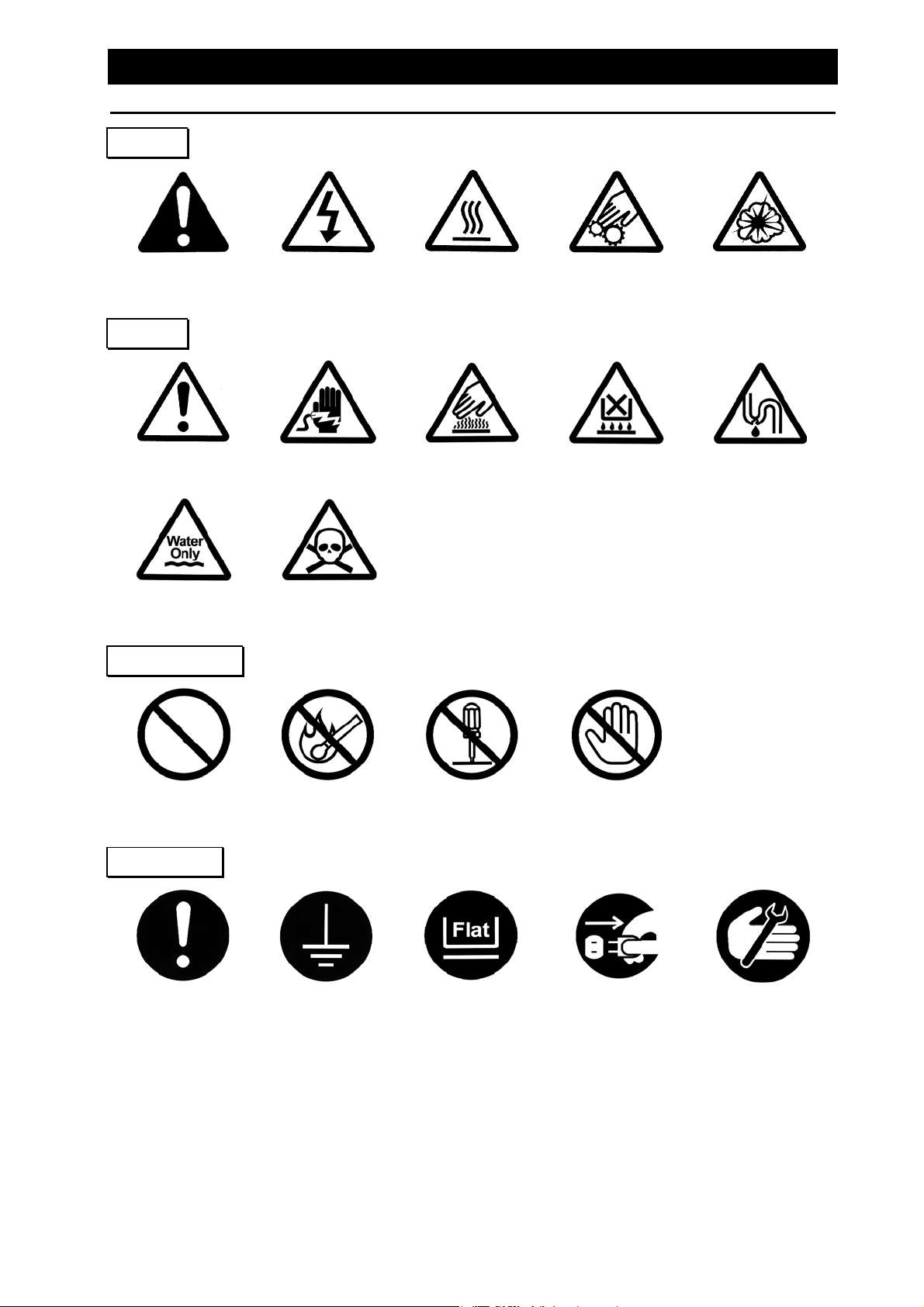
List of symbols
Warning
General warnings
Caution
General cautions Electrical shock! Burning!
For water only
Prohibitions
Danger!: High
voltage
Poisonous
material
Danger!: High
temperature
Danger!: Moving
Caution for no
liquid heating!
part
Danger!: Hazard
of explosion
Caution for water
leak!
General bans Fire ban
Compulsions
General
compulsions
Connect ground
wire
Do not
disassemble
Install levelly
Do not touch
Pull out the power
plug
Regular
inspection
2
Page 5
1.Safety precautions
Warning・Cautions
Warning
Never operate the unit in an atmosphere containing flammable or explosive gas.
Otherwise, an explosion or a fire may result since the unit is not explosion-proof.
See page 37.
Be sure to connect the ground wire correctly. Otherwise, electrical leak may result and cause an
electrical shock or a fire.
When a smoke or a unusual odor is seen or sensed, immediately turn the electric leakage
breaker on the main unit off and pull out the power plug. A fire or an electrical shock may result.
When these are used bundled, they might overheat causing a fire.
Avoid tightly bend, pull with a strong force or twist to prevent electrical power cords from
damaging. A fire or an electrical shock may result.
Never use an explosive material, a flammable material or a material containing them.
Otherwise, an explosion or a fire may result.
See page 37.
Some parts of the unit are hot during and immediately after operation. Take special care for
possible burning.
Never try to disassemble or alter the unit. A malfunction, a fire or an electrical shock may result.
When a thunder is heard, turn the main power off immediately . A malfunction, fire or an electrical
shock may result.
Never operate the unit in an atmosphere containing flammable or explosive gas
Be sure to connect the ground wire.
Ban on operation when an abnormality occurs
Never use electrical power cords bundled.
Take care not to damage electrical power cords.
Never use an explosive or a flammable material with this unit.
Never try to touch a hot part.
Never try to disassemble or alter the unit.
When a thunder is heard.
Caution
3
Page 6
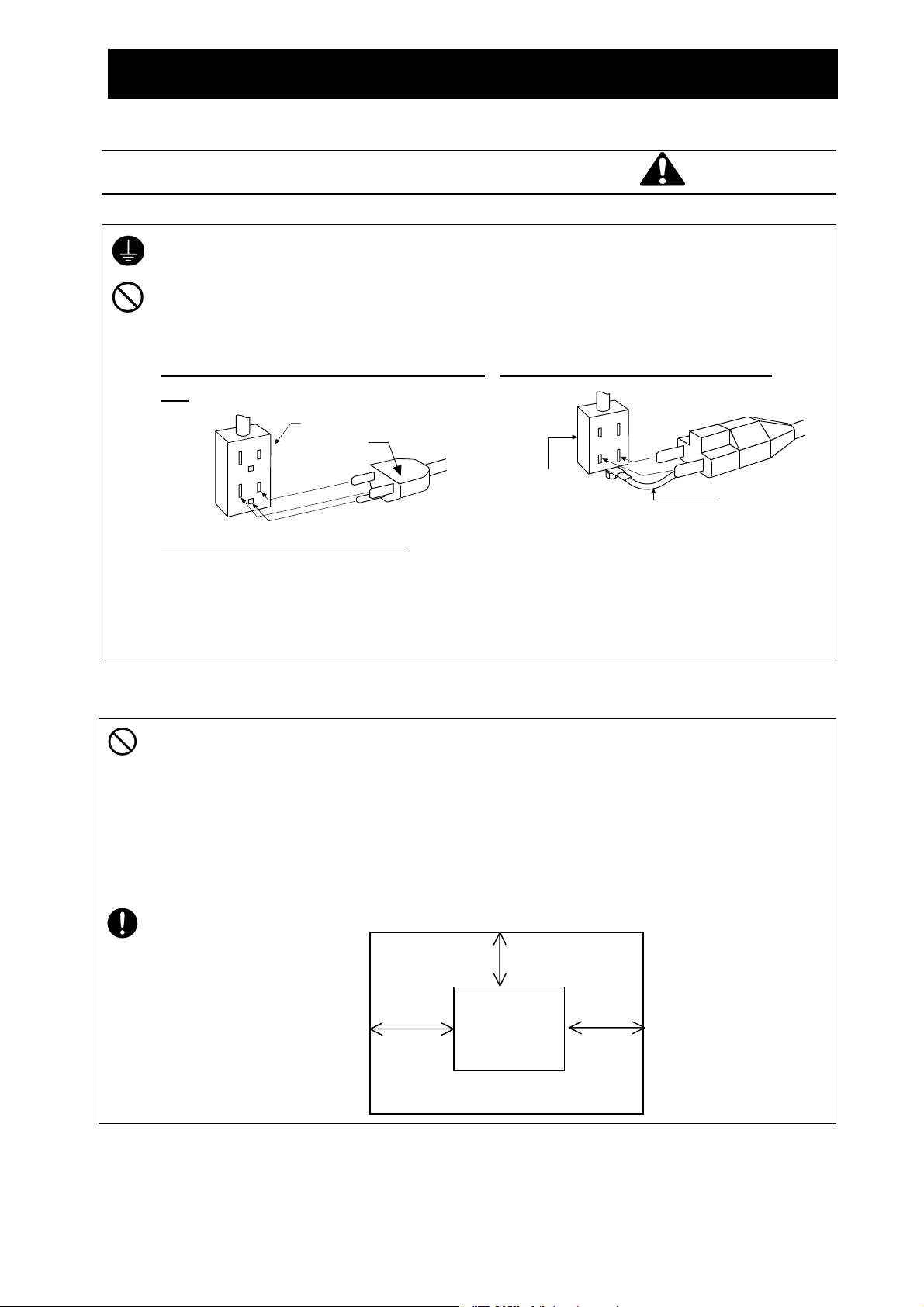
1.Be sure to connect the earth.
Bipol
・ Be sure to connect the earth wire (green core wire of the power cord) to the earth wire or
the earth terminal to avoid an electrical shock due to earth leakage.
・ Never connect the earth wire to a gas pipe or a water pipe. Otherwise, a fire may result.
・ Never connect the earth wire to the earth terminal for a telephone line or to a lightening
conductor. Otherwise, a fire or an electrical shock may result.
・ Never use a branching outlet, which might generate heat and cause a danger.
We recommend use of a ground type outlet
tap.
G
G
When there is no ground terminal.
In this case, class 3 grounding work is
necessary and please consult your dealer or
our nearest sales office.
Grounded receptacle
Power plug
2. Before operating the unit
Precautions on installation
Warning
When a bipolar type outlet tap is used
ar
recep tacle
Insert the ground adaptor included as an option,
into a power plug confirming the polarity of the
outlet. Connect the grounding wire (green) of
the ground adaptor to the ground terminal on
the power supply equipment.
Grounded wire
2. Carefully select an installation site.
Take special care not to install the unit at a place described below:
・Uneven surfaces or dirty surfaces
・Where flammable gas or corrosive gas exists
・ Where the ambient temperature is 35 ℃ or more
・Where temperature changes severely
・Where humidity is high
・Where subject to direct sunlight
・Where vibration is severe
Install this unit at a place with spaces shown below.
15cm or
more
10cm or more
Man body
Front
10cm
or more
4
Page 7
2. Before operating the unit
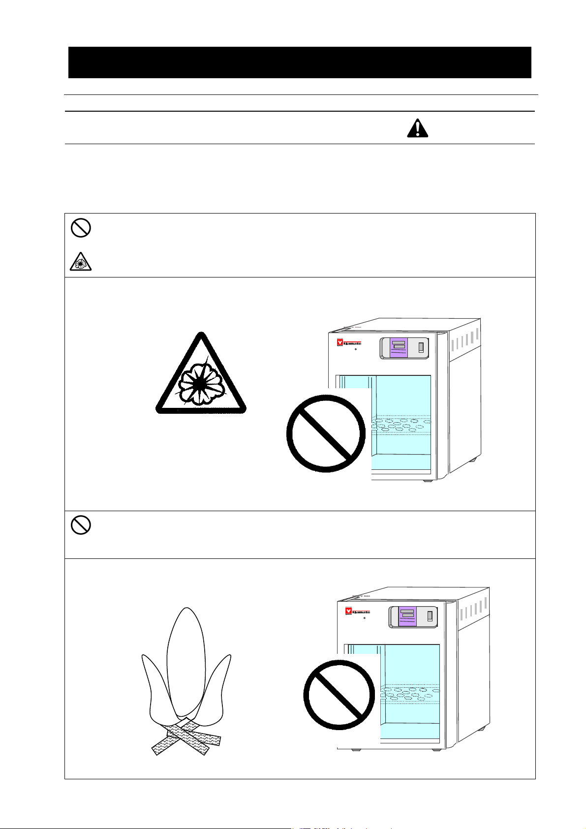
3. Never operate the unit in an atmosphere containing flammable or explosive gas. No
flammable matters
See the section “13. List of dangerous materials” on page 37 for flammable and
explosive gases.
Never operate the unit in an atmosphere containing flammable or explosive gas. Since the unit
is not explosion-proof, an arc is discharged when switching “ON” and “OFF” and during
operation and a fire or an explosion may result.
Precautions on installation
Warning
DO NOT USE
IC101W
Explosive gas
Flammable gas
Do not operate the unit with flammable material inside. Otherwise, a fire may
result.
Do not use
flammable
matters
IC101W
5
Page 8
g
e
2. Before operating the unit
Precautions on installation
Warning
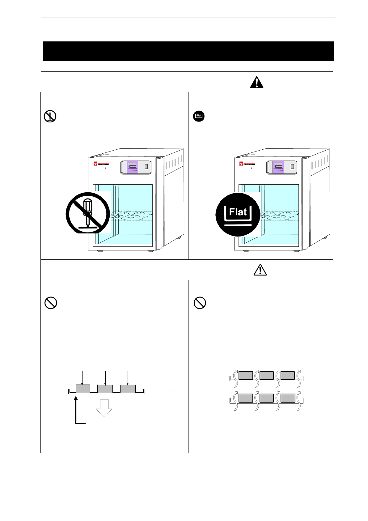
4.Do not attempt to alter the unit 5.Install the unit on a level surface
The customer shall never attempt to alter
the unit. Otherwise a malfunction may
result.
IC101W
Install the unit on a level surface.
Otherwise unexpected troubles or a
malfunction may result.
IC101W
6.Do not put too many specimens.
The withstand load of a shelf board is 10kg
when the load is evenly distributed.
Put specimens dispersed.
7.Do not set too many specimens.
Too many specimens will prevent correct
temperature control. In order to assure
temperature precision, be sure to use
shelf boards and put specimens
dispersed, and secure at least 30% of
space inside the bath.
Specimen
10k
Shelf board
Secure at least 30% of spac
Cautions
6
Page 9

2. Before operating the unit
Precautions on installation
Cautions
8. Connect the power plug to the dedicated outlet
Use an outlet that is suited to the electrical capacity.
When the unit does not start even when power is turned ON, check if main voltage is too low
Electrical capacity
or if the unit is connected to the same power line as other devices. If this is the case, use a
different power line from those for other devices as the power supply.
IC101 AC100V 1.1A
IC101W AC100V 3.1A (While using a service outlet MAX2A)
9. On installation
An earthquake or a shock may cause the unit fall over or move and personal injuries may
result. We recommend exercising safety precautions including selecting an installation place
where less people are passing by.
10. Installation of shelf boards or specimens
The product includes two shelf boards.
One of them is fixed at the lowest stage in the bath. Do not remove this board except when
you install an optional stirrer stand with slide rail.
Set a shelf board at an appropriate position in the bath with included shelf cramps.
The bottom and side surfaces in the bath will become hot. Avoid putting specimens directly
on the bottom surface or allow them to touch with the side surface.
11. Handling of a power cord
Never use electrical power cords bundled. When these are used bundled, they might
overheat causing a fire.
Do not convert, forcibly bend, twist or pull the power cord. Otherwise, a fire or an electrical
shock may result.
Do not place the power cord under a desk or a chair, or sand between objects to avoid it from
being damaged.
Otherwise, a fire or an electrical shock may result.
Do not place the power cord close to a stove or other heat generating device. Sheath of the
cord may burn and result in a fire or an electrical shock.
If the power cord should be damaged (exposure of core wire or disconnection), immediately
turn the ELB off, pull out the power cord (plug) out of the power supply and ask your dealer to
replace the cord. Operating the unit with a damaged power cord may cause a fire or an
electrical shock.
Connect the power cord to an appropriate wall outlet.
7
Page 10
3. Names and functions of each part
Main unit
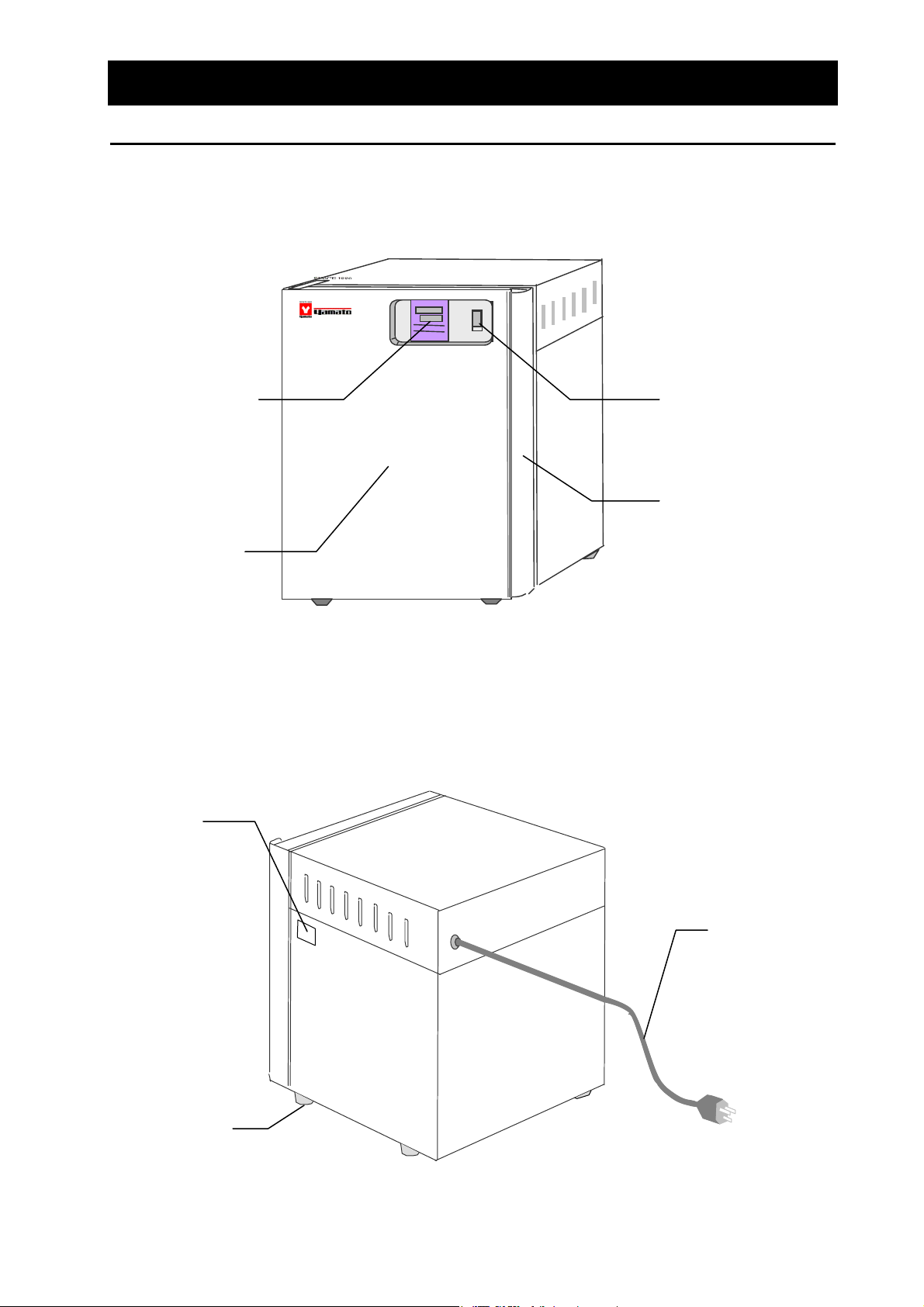
IC101 Front view
IC101
Temperature
controller
Serial number
nameplate
Main switch
(Circuit breaker)
Handle
Door
IC101 Rear view
Rubber foot
Power cord
8
Page 11
3. Names and functions of each part
do
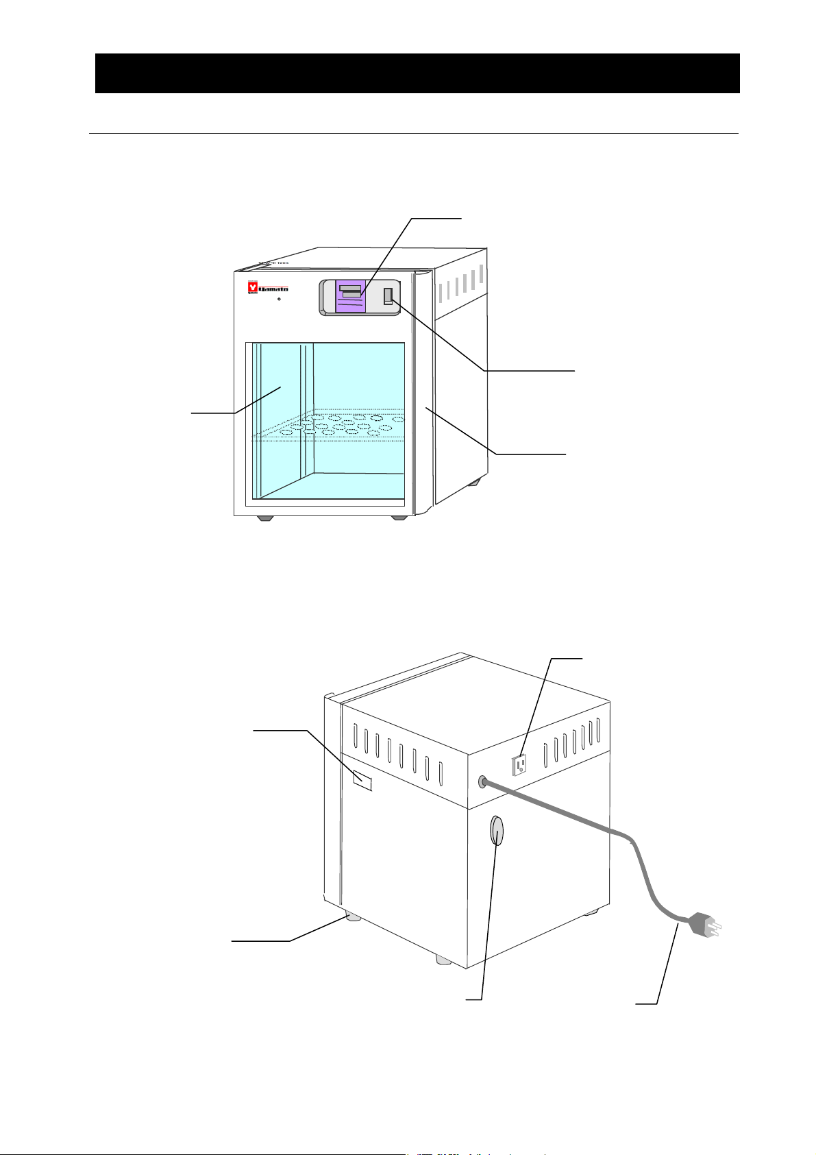
IC101W Front view
Door with
observation
win
w
Main unit
Temperature controller
IC101W
Main switch
(Circuit breaker)
Handle
Serial number
nameplate
Rubber foot
IC101W Rear view
Cable port
Service outlet
Power cord
9
Page 12
3. Names and functions of each part
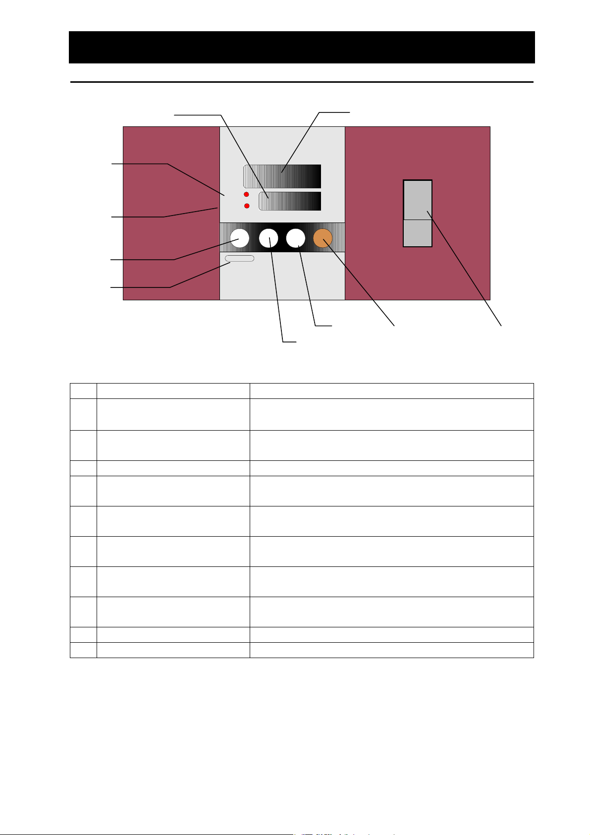
Operation panel
MEASURED TEMP.
① ②
③
ON
OFF
④
⑤
⑥
HEATER
OPERATION
Timer
MAINTENANCE
SET TEMP.
▽ △
START
STOP
℃
I
14.6
×
34.0
○
POWER
⑦
⑧ ⑨ ⑩
No Name Operation/action
MEASURED TEMP. indicator
①
Indicates the measured temperature in the bath, set
characters, and error information.
② SET TEMP. indicator Indicates set temp., functional settings, timer settings, and
remaining time of the timer.
③ HEATER lamp Comes on while power is supplied to the heater.
④ OPERATION lamp Stays on during fixed-setting operation; flashes during timer
operation.
⑤ TIMER key Used for timer operation of quick auto stop, auto stop, and auto
start.
⑥
MAINTENANCE key
Pressing the TIMER longer enters the maintenance mode.
This key is used to select and set various sub-functions.
⑦ Down key The key is used to select a setting. Used to increment the
setting.
⑧ Up key The key is used to select a setting. Used to decrement the
setting.
⑨ START/STOP key The key is used to start or stop operation.
⑩ Power switch(Circuit breaker) Used fo r turning power ON or OFF.
10
Page 13

3. Names and functions of each part
r
Heater construction and operation, features, and recovery time
Heater construction and operation
Control
sensor
Heat
insulato
ヒータ
運転ランプ
タイマ
メンテナンス
Temperature
controller
測定温度
℃
設定温度
スタート
ストップ
▽ △
When you turn the main switch on and
Main switch
ON
14.6
×
34.0
OFF
POWER
press the start key of temperature
controller, the cord heater starts heating
to warm air inside the bath.
The temperature in the bath is controlled
Internal bath
with the temperature controller and the
control sensor and becomes stable at the
Cord
heater
set temperature.
Shelf board
Characteristics of the model IC101/IC101W
The internal wall heating system of this product can keep temperature in the bath at a certain level with
higher precision and has advantages such as spe cimens are not likely to dry like the air jacket system
when compared with a system that uses direct air blasting and circulation.
Since models IC101 and IC101W detect internal bath wall temperat ure with the control sensor and
control and display that temperature with the temperature controller, these have a characteristic that
displayed temperature remains relatively stable even when temperature in the internal bath changes
tentatively during temperature rise or from open/close of the door.
Above all, a symptom that the temperature controller does not show any temperat ure changes even
when the temperature inside the bath shall be low im mediately after opening or clo sing of the door i s one
of the characteristics of this internal bath wall heating system.
Temperature recovery time after opening/closing of the door of models IC101 and IC101W
The temperature will recover in about three to four minutes de pending on the env ironmental tempe rature
or amount of specimen.
(Testing condition:Door open time: 30 sec. Environmental temp.: 23℃)
Functions of the model IC101W
You can install a small stirrer or other devices in the bath of the model IC101. Th e power co rd of a small
stirrer can be connected using the cable port and the service outlet (Max. capacity : 2A) on the rear of the
unit.
In this case, care must be taken for possible heating at the small stirrer in the bath. Devices that
generate heat will influence proper temperature control of the incubator and therefore may be
inappropriate for continued operation for a long time.
IC101W
Service outlet (up to 2 A)
Cable port
11
Page 14

3. Names and functions of parts
Description of characters
Character codes used for the controller will be described below.
Character codes Descriptor Name Application
AStP Auto Stop se ttin g
Used for setting quick auto stop or
auto stop operation.
AStr Auto St a r t setting
End Time up
Pon
cAL Calibration offset setting
Lock Key lock of a setting
※For operation modes and function character codes, see P.15 “Operation mode, function setting keys
and character codes”.
Power failure
compensation setting
Used for setting auto start operation.
Displayed when auto stop timer
operation finishes.
See P.17 and 19.
You can select whether operation shall
continue automatically when
recovered from a power failure or
operation shall remain stopped.
See P.23.
Used for inputting a calibration offset
temperature.
See P.24 “Using the calibration offset
function”.
Locks keys to prevent changes of
settings.
See P.25.
12
Page 15

4. Operating procedures
y
List of operation modes and functions
Operation modes of this unit are as follows.
№ Name Description Page
Operates continuously at the set temperature from start to stop
of operation.
1 Fixed value operation
After turning the main switch ON(I), use the
the temperature.
Press the START/STOP key to start operation and press the
START/STOP key again to stop operation.
Used to “stop operation after several hours in the middle of
operation”.
Press the TIMER ke
during fixed value operation and select
▼▲ keys to set
P.16
Quick auto stop
2
operation
Select
Press the START/STOP key to start quick auto stop operation,
the timer starts in the middle of operation to automatically stop
operation after the set time.
Used to “set auto stop before starting operation”.
First set a temperature with the
3 Auto stop operation
Auto start operation
4
※
※You cannot switch the operation mode to 3 auto stop operation nor 4 auto start operation while
the unit is in operation. First stop operation when you want to change the operation mode.
Then press the TIMER key to select
you want with the ▼▲ keys.
Press the START/STOP key to start auto stop operation.
Used to “start auto start automatically after certain hours”.
First set a temperature with the
Then press the TIMER key to select
time you want with the ▼▲ keys.
Press the START/STOP key to start auto start operation.
. You can set a time until operation stops.
and set a time using the ▼▲ keys.
▼▲ keys.
and set a time
▼▲ keys.
and set a
P.17
P.19
P.21
13
Page 16

4. Operating procedures
List of operation modes and functions
Operation functions of the unit are as follows.
№ Name Description Page
:
-
P.23
P.24
P.25
Overheat prevention
1
function
Power failure
2
compensation function
Calibration offset
3
function
4 Setting lock function
Automatic overheat prevention function
The function is set to activate automatically (automatically
return) at a temperature 6
it has risen together with the unit set temperature.
Overheat preventive device
A bimetal overheat preventive device of manual recovery
type is installed.
If the overheat preventive device has activated, the u nit
will stop and will not recover until the recovery button of
the device is pressed.
Call for service when the overheat preventive device is
activated.
When a power failed during operation, operation resumes at
the state immediately before the power failure. (The unit
may remain stopped in the timer operation mode.)
If you want to keep operation stopped when recovering from
a power failure, cancel the power failure compensation
function (OFF).
The calibration offset function is a function that compensates
errors by 1
controlled temperature (indicated temperature) when the
temperature in the bath is controlled to a value different from
the set temperature.
Compensation can be made for plus or minus side.
This function locks the set status currently in operation.
You can set or cancel the function with the SUB MENU key.
℃ between the set temperature and the
℃ above that in t he bath when
:
(Manual recovery)
Service outlet
5
(Model IC101W only)
1. Customer cannot change the setting of the item 1.
2. Functions in the items 2, 3, and 4 can be set using the maintenance function (MAINTENANCE) key.
This is a service outlet useful to use a small stirrer. Run the
power cord through the cable port on the r ear of the main
unit. The maximum capacity is 2 A.
14
P.26
Page 17

4.Operating procedures
A
e
t
Operation mode, function setting keys and character codes
Operation modes and functions require the following key operations and character codes
below for setting.
Main switch
ON
Indication of
initial screen for
4 sec.
Fixed value operation
wait screen
Note:Check set temperature
Maintenance mode
Useful function
Timer
Switch to mainten ance mode by pressing
TIMER key longer.
Fixed value
operation
1sec
Fixed value
operation
Fixed value
operation temp
change
Temp. setting
Fixed value
operation
Start/
Stop
Quick auto stop
operation
Timer
Auto s top
operation
Timer
uto start
operation
Timer
Time setting
Time setting
Start/
1sec
Stop
Timer operation
start
Stop operation
automatically
Start/
1sec
Stop
Returns to the fixed
value operation wait
screen
Time setting
Start/
1sec
Stop
Timer operation
start
Stop operation
automatically
Start/
1sec
Stop
Returns to the fixed
value operation wait
screen
Start/
1sec
Stop
Start fixed valu
operation at se
time
Stop operation
automatically
Start/
1sec
Stop
Returns to the fixed
value operation wait
screen
Operation lock
setting
Set during
operation
Timer
Press TIMER key once
OFF ON
ON to lock keys
OFF to release
Calibration
offset
Set during
operation
Timer
Press TIMER key twice
Temp. UP Temp. DOWN
▽ to increase in-bath
temp
△ to decrease in-bath
temp.
Power failure
compensation
Set before
operation
Timer
Press TIMER key thrice
OFF ON
ON to turn power failure
compensation func ON
OFF to turn power failure
compensation func OFF
15
Page 18

4. Operating procedures
Operating procedures(fixed value operation)
Procedures for fixed value
operation
HEATER
OPERATION
MAINTENANCE
Timer
MEASURED TEMP.
SET TEMP.
▽ △
℃
START
STOP
MEASURED TEMP.
HEATER
OPERATION
SET TEMP.
MEASURED TEMP.
HEATER
TIMER
MAINTENANCE
OPERATION
SET TEMP.
ON
14.6
×
34.0
OFF
POWER
℃
℃
START
STOP
1. Turn the main switch on. (Turn the switch to “I”.)
Turning the switch on will display the initial values for
about four seconds, then the screen will change to the
initial setting screen and indicators show the current
in-bath temperature and the last set temperature.
MEASURED TEMP. screen
: Displays the current
temperature in the bath
SET TEMP screen:Displays the last set temperature
2. Setting the temperature
Set the temperature you want using the ▼▲ keys.
MEASURED TEMP.
℃
START
STOP
TIMER
MAINTENANCE
HEATER
OPERATION
SET TEMP.
Changing the temperature
3. Starting operation
Press the START/STOP key longer.
The fixed value operation will start and the operation lamp
and the heater lamp will come on.
4. Stopping operation
Press the START/STOP key longer.
The operation will stop, the operation lamp will go off and
the screen will change to the initial setting screen.
You can change the set temperature by simply pressing the
▼▲ keys.
Pressing the
▼▲ keys during operation immediately b rings
you to the setting mode where you can change the
temperature.
After setting a new temperature, wait a while until the new
temperature will be active and then the screen returns to the
previous one.
16
Page 19

4. Operating procedures
Operating procedures(Quick auto stop operation)
This is used to “stop operation automatically after several hours in the middle of the fixed value
operation”.
The quick auto stop operation allows setting of auto stop timer during operation.
How to start auto stop
operation
MEASURED TEMP.
℃
②
START
STOP
TIMER
MAINTENANCE
HEATER
OPERATION
①
SET TEMP.
1. Setting time before stop during fixed value operation
Confirm that the operation lamp is on, which indicates
①
the unit is in operation.
Press the TIMER key.
The character AstP t hat indicat es the auto stop
operation mode appears in the MEASURED TEMP.
screen and the set time flashes in the SET TEMP
screen.
② Use the ▼▲ keys to set the time you want.
About the timer function
MEASURED TEMP.
HEATER
OPERATION
SET TEMP.
TIMER
MAINTENANCE
MEASURED TEMP.
HEATER
OPERATION
SET TEMP.
TIMER
MAINTENANCE
℃
START
STOP
1 sec
℃
START
STOP
1 sec
The maximum settable time of the timer is 999 hours 50
minutes.
You can set time in the unit of minutes up to 99 hours 59
minutes.
Time of 100 hours or longer shall be set in the unit of 10
minutes.
You can continuously change the set t ime and find the time
you want quickly by keeping the
adjust the time, press the
▼▲ keys for one digit at a time.
▼▲ ke ys pressed. To fine
2. Starting the timer operation
When you have set the time you want, press the
START/STOP key again while it is flashing.
The operation lamp will flash and timer operation will start.
Note
: Timer counting starts when the temperature in the
bath reaches the set temperature.
When the timer starts counting, the SET TEMP
screen will switch to the remaining time indication.
3. Stopping/finishing the timer operation
When the set time has passed, the timer will stop
automatically but the character End
flashes in the
set temperature indicator to indicate that operation has
finished.
To return to the initial setting screen, press the
START/STOP key longer f or about one second to finish
the timer operation mode.
The screen will return to the initial setting screen.
17
Page 20

4. Operating procedures
Operating procedures(quick auto stop operation)
To change the set
temperature or the set time
Pressing the ▼▲ keys during operation immediately brings
you to the setting mode where you can change the
temperature.
Pressing the TI MER key during operation immediately brings
you to the setting mode where you can change the set time.
In this case, you need to set a time obtained by addin g time
that has already passed to time you want to add.
After you have changed time, press the START/STOP key to
finish.
The remaining time indication
down while its dot is flashing.
When the dot stays on, it indicates the wait status
(temperature is increasing or decreasing to the set
temperature) during which timer count is stopped.
indicates count
18
Page 21

4. Operating procedures
Operating procedures(auto stop operation)
The timer is set from the start of fixed value operation and the operation is automatically stopped when
the set temperature comes.
How to start auto stop
operation
MEASURED TEMP.
℃
②
START
STOP
TIMER
MAINTENANCE
HEATER
OPERATION
①
SET TEMP.
1. Setting the stop time
Confirm that the temperature you wa nt is set and then
①
press the TIMER key.
The character AStP that indicates the auto stop
operation appears in the MEASURED TEMP. and th e
set time flashes in the SET TEMP screen.
② Use the ▼▲ keys to set the time you want.
About the timer function
MEASURED TEMP.
HEATER
OPERATION
TIMER
MAINTENANCE
MEASURED TEMP.
HEATER
OPERATION
TIMER
MAINTENANCE
SET TEMP.
SET TEMP.
The maximum settable time of the timer is 999 hours 50
minutes.
You can set time in the unit of minutes up to 99 hours 59
minutes.
Time of 100 hours or longer shall be set in the unit of 10
minutes.
You can continuously change the set t ime and find the time
you want quickly by keeping the
adjust the time, press the
▼▲ keys for one digit at a time.
▼▲ ke ys pressed. To fine
2. Starting the timer operation
When you have set the time you want, press the
ST AR T/STOP key longer for about one second. Press the
℃
START/STOP key longer for about one second.
The operation lamp flashes and the timer operation starts.
START
STOP
Note:T imer counting starts when the temperature in the bath
reaches the set temperature.
When the timer starts counting, the SET TEMP screen will
switch to the remaining time indication.
3. Stopping/finishing the timer operation
When the set time has passed, the unit will stop operation
automatically.
℃
The character End
fl ashes in the set temperature
indicator to indicate that operation has finished.
START
STOP
Press the START/STOP key longer for about one second
to finish the timer operation mode. The screen will switch
to the initial setting screen.
19
Page 22

4. Operating procedures
Operating procedures (auto stop operation)
To change the set
temperature or the set time
Pressing the ▼▲ keys during operation immediately brings
you to the setting mode where you can change the
temperature.
Pressing the TIMER key during operation immediately brin gs
you to the setting mode where you can change the set time.
In this case, you need to set a time obtained by addin g time
that has already passed to time you want to add.
The remaining time indication
while its dot is flashing.
When the dot stays on, it indicates the wait status
(temperature is increasing or decreasing to the set
temperature) during which timer count is stopped.
indicates count down
20
Page 23

4. Operating procedures
Operating procedures(auto start operation)
The mode starts operation automatically after the time set with the timer has passed.
Note that the operation will not stop automatically but must be stopped manually in this mode.
To start auto start operation
MEASURED TEMP.
℃
②
START
STOP
TIMER
MAINTENANCE
HEATER
OPERATION
①
SET TEMP.
1. Setting the operation start time
Confirm that the temperature you want has been set
①
and press the TIMER key.
The character AStr that indicates the auto start
operation appears in the MEASURED TEMP. screen
and the set temperature flashes in the SET TEMP.
screen.
② Use the ▼▲ keys to set the time you want.
About the timer function
MEASURED TEMP.
HEATER
OPERATION
SET TEMP.
TIMER
MAINTENANCE
MEASURED TEMP.
HEATER
OPERATION
SET TEMP.
TIMER
MAINTENANCE
℃
START
STOP
℃
START
STOP
The maximum settable time of the timer is 999 hours 50
minutes.
You can set time in the unit of minutes up to 99 hours 59
minutes.
Time of 100 hours or longer shall be set in the unit of 10
minutes.
You can continuously change the set time and find the time
you want quickly by keeping the
▼▲ keys pressed. To fine
adjust the time, press the ▼▲ keys for one digit at a time.
2. Starting the timer operation
When you have set the time you want, press the
START/STOP key long er for about one second while it is
flashing.
Timer counting starts when the START/STOP key is
pressed.
The MEASURED TEMP. screen switches indication from
the set time to the remaining time.
Operation starts automatically when the set time comes
and the operation lamp will come on.
3. Stopping/finishing the timer operation
To stop operation, press the START/STOP key longer for
about one second to finish the timer operat ion mode. The
screen will switch to the initial setting screen.
21
Page 24

4. Operating procedures
Operating procedures(auto start operation)
To change the set
temperature or the set time
If you want to change the set temperature or the set time during
operation, press the TIMER key during operation and set the
temperature or time for auto start operation using the ▼▲ keys.
However, to change the set time, you need to set a time obtained by
adding time that has already passed to time you want to add.
Note
:You cannot change time once the auto start time has passed and
operation has started. Since the operation mode is fixed value, f irst
stop operation using the START/STOP key and make set tings from
the beginning.
22
Page 25

4. Operating procedures
Useful functions(power failure compensation function)
When a power failure occurs in the middle of operation, the unit resumes operation in the state
immediately before the power failure after recovering from the power failure.
(The unit may remain stopped in the case of timer operation.)
If you want to keep the unit stopped when recovering from a power failure, release t he power failure
compensation function (OFF).
MEASURED TEMP.
③
℃
START
STOP
MAINTENANCE
②
TIMER
HEATER
OPERATION
SET TEMP.
① Operate the unit with the initial screen status.
② Press the TIMER key longer to switch to the
MAINTENANCE menu mode. (You are already in the
MAINTENANCE menu mode if LOCK
appears.
)
indication
Press the TIMER key several times to select the
character Pon that indicates the power failure
compensation function.
③ Turn “on” in the MEASURED TEMP. screen to “oFF”
using the
▼ key and you have finished setting.
23
Page 26

4. Operating procedures
p
Useful functions(calibration offset function)
Using the calibration offset
function
The calibration offset function is a function that compensates
differences that may be generated between the temperature
in the bath and the set temperature.
This function can make parallel compensation to the plus or
minus side for the entire temperature range. You can
set/release using the MAINTENANCE key.
The offset is set at “0” at the time of shipping from the factory.
Controlled temp.
after minus
compensation
Current
tem
Controlled temp.
after plus
compensation
erature
① Start operation at the target set temperature, and after
the temperature has become stable, check the
MAINTENANCE
③
MEASURED TEMP.
HEATER
OPERATION
TIMER
SET TEMP.
℃
④
START
STOP
temperature in the bath with a temperature recorder.
② Check difference between the set temperature and the
temperature in the bath.
③ Press the TIMER key longer to switch to the
MAINTENANCE menu mode. (You are already in the
MAINTENANCE menu mode if LOCK
appears.
)
indication
Press the TIMER key several times to select the
character cAL that indicates the calibration
offset function.
④ Enter the difference between the set temperature and
the temperature in the bath using the
▼▲ keys to
complete setting.
※ Offset temperature may be set to either of + or – side.
Setting to the
- side will decrease the displayed
measured temperature by the offset amount while the
temperature in the bath will increase by the same
amount.
Setting to the
+ side will increase the displayed
measured temperature by the offset amount while the
temperature in the bath will decrease by the same
amount.
Note: Temperature in the bath changes tentatively immediately after placing a specimen. Therefore,
wait until the temperature in the bath become stable before checki ng for a temperature
difference.
24
Page 27

4. Operating procedures
Useful functions(setting key lock function)
The function is to lock the settings during operation for safety. You can set or release this function
with the MAINTENANCE
MEASURED TEMP.
HEATER
OPERATION
SET TEMP.
TIMER
MAINTENANCE
MEASURED TEMP.
HEATER
OPERATION
SET TEMP.
TIMER
MAINTENANCE
key.
① Press the TIMER key longer to switch to the
MAINTENANCE menu mode.
℃
Press the TIMER key to select the character
Lock that indicates the settings lock.
START
STOP
② "oFF” will appear in the SET TEMP screen. You can
switch this to “on” with the
℃
▲ key to lock the settings.
START
STOP
MEASURED TEMP.
℃
START
STOP
TIMER
MAINTENANCE
HEATER
OPERATION
SET TEMP.
③ If you want to cancel lock, press the TIMER key longer
again and select the character Lock that
indicates the setting lock using the
Selecting “oFF” with the
▼ key releases the lock.
▼▲ keys.
※ While the lock function is “on”, any keys other than
the START/STOP key and TIMER key are locked.
25
Page 28

4.Operating procedures
Useful functions (Using the service outlet)
Using the service outlet(Model IC101W only)
Model IC101W has a useful service outlet to which a device up to 2 amperes can be connected.
This outlet can be used as a power supply for a small stirrer or other device that can be installed
on the IC101W.
Service outlet(Up to 2A)
Power cord of the small stirrer
Small stirrer
Operational precautions
・
・ When a device that generates heat has been installed, proper temperature control may not
・ Install an optional stirrer stand with slide rail if you want to install a small stirrer.
・ The bottom surface and walls in the bath will hot and avoid putting specimen directly on the
When a small stirrer has been installed, operate the unit at 45℃ or lower set temperature to
protect the stirrer.
be possible.
If this occurs, stop using that device.
bottom surface or allow them to touch with the side surface.
Cable port
26
Page 29

5. Handling precautions
1.About materials that cannot be used
Never use an explosive material, a flammable material, or a material that contains such
materials for this unit. They may cause an explosion or a fire. (See P.37 “List of dangerous
materials”.
2.About banning of operation/solutions when an abnormality occurs
When smoke or strange odor is generated from this unit for some reason, immediate turn
power of the unit off, shut the power supply off and ask inspection to your dealer, one of our
sales offices, or the customer center. Leaving the unit as it is may cause a fire or an electrical
shock. The user must not attempt a repair, which may cause a danger.
1. Do not put any object on the unit
Do not put any object on the unit. It might fall off and cause a personal injury.
2. During a thunder storm
When a thunder begins, immediately turn power of the unit off, shut the power supply off.
Leaving the unit as it is might cause a malfunction or a fire from lightening.
)
Warning
Caution
3. When opening or closing the door
When opening or closing the door, do not put your hands or face close to the area (space)
where the door moves.
The door might hit the hand or the face and cause an injury.
4. Banning of use of corrosive materials
Although inside the bath is made of SUS304 stainless steel, it might corrode from a strong
acid. The door packing is made of silicone rubber. Take care it might corrode with acid,
alkaline, oil, or halogen based solvent.
5. Operate the unit at an appropriate temperature
The operational temperature range is +5℃~60℃ room temperature.
Never operate the unit at a temperature out of the operational temperature range.
6. Placement of specimen
The withstand load of a shelf board is 10kg. Do not put a specimen exceeding this limit.
Put two or more specimens dispersed.
Putting too many specimens may cause imperfect transmission of heat to them and prevent
even heating. Make sufficient spaces between specimens.
27
Page 30

5.Handling precautions
7. About recovery from a power failure
When power is recovered after stoppage from power failure during operation, the unit
automatically returns to the state immediately before power failure and resume operation.
Set the power failure compensation function of the sub menu functions OFF if you do not
want to allow the unit to automatically resume operation. See P.23.
8. About stacking in two layers
You can stack the units up to two layers only using the special stacking fittings of optional
accessories.
Never stack the units in three or more layers.
9.After installation
An earthquake or a shock may cause the unit fall over or move and personal injuries may
result. Implement appropriate fall-over preventive measures for safety.
Caution
28
Page 31

6. Maintenance procedures
Daily inspection/maintenance
Warning
● Be sure to pull out the power cord unless necessary before trying to do inspection and maintenance
works.
● Start these works after the device has returned to the normal temperature.
● Never try to disassem ble the unit.
Caution
● Wipe off any dirt with a tightly wrung soft cloth. Never try to clean the unit with benzene, thinn er or
scouring powder, or rub with a scrubbing brush. Deformation, degradation or discoloration may
result.
29
Page 32

7. When the unit is not to be used for a long time
or when disposing
When the unit is not to be used for a long time or when disposing
Caution
When the unit is not going to be used for a long
time
● Turn the power to off and pull out the power
cord.
Warning
When disposing the unit
● Do not leave the unit in the area where children
may have access.
● Be sure to remove handles before disposing
the unit to prevent the doors from locking.
● In general, dispose the unit as a bulky waste.
Notes about disposition
Always pay attention to the preservation of the global environment.
・ We highly recommend taking the unit apart as far as possible for separation or recycling to
contribute to the preservation of the global environment. Major components and materials for the
unit are as follows:
Names of major components Major materials
Major components
Chassis Steel sheet iron, melamine resin baking finish
Interior Stainless steel SUS304
Observation window (only
IC101W)
Insulating material Glass wool
Door packing Silicon rubber
Nameplates Polyethylene (PET) resin film
Major electric parts
Heater
Boards
Power cord & wiring materials,
etc.
Reinforced glass, Silicon rubber
SUS
-Chrome heater
Resin, board, condenser, resistor, transformer, or other
composite parts
Wiring materials with resin cladding
30
Page 33

8. When a trouble occurs
Safety device and error codes
The table below shows the possible causes and solutions for a trouble and a safety device has
activated.
[Error code]
When an operational abnormality or a malfunction occurs, “MALFUNCTION” sign and an error
code will appear on the operation panel. When a malfunction occurs, note the error code and
immediately stop operation.
Safety device Symptom Possible causes and solutions
Wrong temperature
input
Malfunction of
memory
Abnormal measured
temperature
Abnormal measured
temperature
Alarm lamp on
indication
Alarm lamp on
indication
No indication z When the automatic overheat preventive
All function stop z When the independent overheat preventive
z Abnormal temperature input circuit
z Disconnection or malfunction of the
temperature sensor
z The measured temperature is out of the
display range.
Contact the customer service center.
z Abnormal settings in memory
Contact the customer service center.
device activated due to abnormal increase in
temperature in the bath.
Contact the customer service center.
device activated due to abnormal increase in
temperature in the bath.
Contact the customer service center.
About the activation of the circuit breaker(main switch)
The unit is equipped with a circuit breaker with the main switch function.
When excessive current flows through the unit for some reason, the circuit breaker will turn OFF
I to
○) and shut the power off. To recover, first remove the causes and then turn the switch ON
again.
○
I
When the breaker activates, the switch
returns from I to
○.
(from
31
Page 34

8. When a trouble occurs
If a malfunction is suspected
In the following cases
Symptom Possible Causes
The unit will not start
even if power is turned
on.
Temperature changes
during operation.
There is a difference
between the set
temperature and the
temperature in the
bath.
◆When the symptom does not correspond to any of the above, immediately turn the pow er
switch off, pull out the power plug and contact your dealer, one of our sales offices, or our
customer service center.
● Power plug is not connected to the receptacle correctly.
● Power failure.
● Too many specimens are placed.
● Air from an air conditioner is blowing directly against.
● Outside temperature is too low.
● Changes in the environmental temperature are too large.
● Specimen may contain too much water.
● Source voltage may be too low.
● The temperature compensation value of the calibration offset
may be too small or too large. Set the compensation to ±0
once and wait until the temperature in the bath becomes stable (after
about two hours), reenter the correct compensation value.
(See P.24.)
32
Page 35

9. After sales service and warranty
When requesting a repair
When requesting a repair
If any trouble occurs, immediately stop operation, turn the power switch off, pull out the power plug and
contact your dealer, our sales office or our customer service center.
Information necessary for requesting a repair
● Model name of the product
● Serial number
● Date (y/m/d) of purchase
● Description of trouble (as in detail as possible)
Be sure to indicate the warranty card to our service representative.
See the warranty card or the nameplate on the unit.
(See P.8
~P.9).
Warranty card (attached separately)
● Warranty card is given by your dealer or one of our sales offices and please fill in your dealer,
date of purchase and other information and send it to our customer service center by Facsimile
(03-3231-6523). Then, store it securely.
Warranty period is one full year from the date of purchase. Repair service for free is available
●
according to the conditions written on the warranty card.
For repairs after the warranty period consult your dealer, one of our sales offices or our
●
customer service center.
Paid repair service is available on your request when the product’s functionality can be
maintained by repair.
Minimum holding period of repair parts
The minimum holding period of repair parts for this product is seven years after end of production.
Repair parts here refer to parts necessary for maintaining performance of the product.
33
Page 36

10. Specifications
Specification of the main unit
Product name Incubator
Model IC101 w IC101
System
Exterior material
Interior material Stainless steel
Heater Silicon code heater:100W
Cable hole Inner dia. 30φ x 1
Observation window 290W×240H Dual semi-reinforced
Construction
Service outlet An outlet 3P Max 2A
Operation temperature
range
Temperature control
precision
Temperature distribution
precision
Performance
Time to attain the max.
temperature
Temperature controller
Controller PID control, digital setting
Temperature sensor K-thermocouple
Temperature control
system
Temperature setting
system
Control
Timer resolution 1 minute (0 hour 00min―99 hours 59mins)
Temp. controller alarm
function
Overheat prevention unit Manual recovery bimetal (70℃)
Safety
function
Main switch Circuit breaker(locker switch type)
Operation function
External dimension 410 x 380 x 520
Internal dimension 350 x 300 x 360
Capacity 37L
Power supply AC100V 50/60Hz 3.1A
Standard
Power cord 3P cord with plug
Weight Approx.17Kg Approx.16kg
Accessories 2 sets of shelf boards(One is fixed in the bath), operating instruction,
Optional parts
* Performance is measured with the power of AC100V.
* The operation temperature range of the unit is 5℃~35℃. Note that a lower environmental temperature ma y
prolong temperature attainment time or enlarge difference between set temperature and that in the bath. We
recommend using the unit at the environmental temperature of 18℃~30℃.
External dimensions exclude protruding parts.
*
Internal bath wall heating natural convection system
Steel plate, melamine b ake d finishing
glass
Room temperature of +5℃ to 60℃
±0.5℃(at37℃)
±1.5℃(at37℃) ±1.0℃(at37℃)
Approx. 40 minutes
PID control by micro computer
Up/Down key
Setting by 1 minute up to 99 hours 59mins
Setting by 10 minutes from 100 hours
Automatic overheat prevention function:Set temperature +6℃ main
relay shut-off (Auto recovery)
Operation functions: fixed value, quick auto stop, auto stop, auto start
Functions: operation key lock, calibration offset, power failure
compensation
AC100V 50/60Hz 1.1A
Service outlet 2A included
warranty card
Stacking fittings
Set of shelf boards
Stirrer stand with slide rail (IC101 w
only)
34
Page 37

Wiring diagram
(IC101/IC101W)
OH
AC100V
T:Model IC101W only
Model IC101 does not have a service outlet.
MBC
TB
T
H
1
2
3
2
4
SSR
1
Symbol Part name
MCB Main switch
(Circuit breaker)
H Cord heater TH K sensor for control
TB Terminal block OH Overheat preventive bimetal
T Service outlet (IC101w only) SSR Contact less relay
11. Wiring Diagram
9
8
7
6
5
4
-
TH
3
4
3
2
+
1
Symbol
TC Temperature controller
CONT
22
1
Part name
22
1
PIO
35
Page 38

12. List of replacement parts
Replacement parts for IC101/IC101W
Part Name Specification Manufacturer Code No.
Control board for
1
temperature controller
display board for
2
temperature controller
3 K sensor for control
4 SSR TRS5225 Toho Denshi 2160000035
5 Power cord kit
6 Circuit breaker 3130-F110 10A
Overheat preventive
7
device
Cord heater
8
9 Terminal block TBF-250ABC-4P
10 Service outlet
CN40BY-IC
CN40BY-IC
φ0.32 K-thermocouple,
with protective tube
1.25
sq3Pwith plug 2 m
Manual recovery bimetal 70
Silicon cord heater
S-150 125V 15A
100W
℃
Yamato
Scientific
Yamato
Scientific
Yamato
Scientific
Yamato
Scientific
ETA
components
Matsuo
electric
Yamato
Scientific
Sakazume
electric
Sato parts LT00002360
LT00007640
LT00007639
LT00009502
LT00001745
LT00001299
LT00002216
LT00020099
LT00002219
36
Page 39

Explosive
substance
13. List of dangerous materials
Never use an explosive substance a flammable substance or a substance
containing them for this device.
① Nitroglycol, glycerine trinitrate, cellulose nitrate and other explosive nitrate esters
② Trinitrobenzen, trinitrotoluene, picric acid and other explosive nitro compounds
③ Acetyl hydroperoxide, methyl ethyl ketone peroxide, benzoyl peroxide and other
Explosive
substance
organic peroxides
Metal “lithium”, metal “potassium”, metal “natrium”, yellow phosphorus, phosphorus
sulfide, red phosphorus, celluloids, calcium carbide (a.k.a, carbide), lime phosphide,
magnesium powder, aluminum powder, metal powder other than magnesium and
Explosive
aluminum powder, sodium dithionous acid (a.k.a., hydrosulphite)
substances
① Potassium chlorate, sod iu m ch lora te , ammon i um ch lo ra te , a nd o ther ch lo ra te s
② Potassium perchlorate, sodium perchlorate, ammonium perchlorate, and other
perchlorates
③ Potassium peroxide, sodium peroxide, barium peroxide, and other inorganic
peroxides
④Potassium nitrate, sodium nitrate, ammonium nitrate, and other nitrates
⑤ Sodium chlorite and other chlorites
Oxidizing substances
⑥ Calcium hypochlorite and other hypochlorites
① Ethyl ether, gasoline, acetaldehyde, propylene chloride, carbon disulfide, and othe r
substances with ignition poin t a t a de gree 3 0 or more degrees below zero.
② n-hexane, ethylene oxide, acetone, benzene, methyl ethyl ketone and other
Flammable substances
Combustible
(Quoted from the separate table 1 in Article 6, the enforcement order of the Industrial
substances with ignition point between 30 degrees below zero and less than zero.
③ Methanol, ethanol, xylene, pentyl acetate, (a.k.a.amyl acetate) and other
substances with ignition point between zero and less than 30 degrees.
④ Kerosene, light oil, terebinth oil, isopenthyl alcohol(a.k.a. isoamyl alcohol), acetic
acid and other substances with ignition point between 30 degrees and less than 65
Flammable substances
degrees.
Hydrogen, acetylene, ethylene, methane, ethane, propane, butane and other
gas
Substance which is a flammable gas at 15
℃, one air pressure.
Safety and Health Law
37
Page 40

Limited liability
Be sure to use the unit strictly following the handling and operating instructions in this
operating instruction.
Yamato Scientific Co.,Ltd. assumes no responsibility for an accident or a malfunction
caused by use of this product in any way not specified in this operating instruction.
Never attempt to perform matters prohibited in this operation instruction.
Otherwise, an unexpected accident may result.
Notice
● Descriptions in this operating instruction are subject to change without notice.
● We will replace a manual with a missing page or paging disorder.
Operating instruction
Incubator
IC101/IC101W
3rd edition 1 August, 2007
Revised 22 February, 2012
Yamato Scientific Co.,Ltd.
〒103-8432
2-1-6, Nihonbashi, Honcho, Chuo-ku, Tokyo
Customer Service Center
Tool free: 0120-405525
http://www.yamato-net.co.jp
 Loading...