

Page 1

Model High -TechⅣ
Ⅳ
ⅣⅣ
Programmable Controller
Operating Instructions
Version 2
Yamato Scientific Co., Ltd
Page 2

1111. INTRODUCTION
. INTRODUCTION ................................
. INTRODUCTION. INTRODUCTION
Explanation of Character on the display
Explanation o f Character on the d i s play................................
Explanation of Character on the displayExplanation of Character on the display
2.
2. INPUTTING, EDITION AND DELETING PROGRAMS
INPUTTING, EDITION AND DELETING PROGRAMS ......................
2.2.
INPUTTING, EDITION AND DELETING PROGRAMS INPUTTING, EDITION AND DELETING PROGRAMS
2.1 Program Composition
2.1 Program Composition................................
2.1 Program Composition2.1 Program Composition
2.2 Inputting Programs
2.2 Inputting P r ogra ms ................................
2.2 Inputting Programs2.2 Inputting Programs
2.3 Editing Programs
2.3 Editing Pr o gra ms................................
2.3 Editing Programs2.3 Editing Programs
2.4 Deleting Programs
2.4 Deleting Progra ms ................................
2.4 Deleting Programs2.4 Deleting Programs
3. INPUTTNG AND SETTING FUNCTIONS
3. INPUTTNG AND SETTING FUNCTIONS................................
3. INPUTTNG AND SETTING FUNCTIONS3. INPUTTNG AND SETTING FUNCTIONS
3.1 Switching between Time and Period
3.1 Switching between T ime and Period ................................
3.1 Switching between Time and Period3.1 Switching between Time and Period
3.2 Setting and Releasing Panel Key Lock
3.2 Setting and R eleasing Panel Key Lock................................
3.2 Setting and Releasing Panel Key Lock3.2 Setting and Releasing Panel Key Lock
3.3 Turning ON and OFF Buzzer Sound
3.3 Turning ON an d OFF Buzzer Sound ................................
3.3 Turning ON and OFF Buzzer Sound3.3 Turning ON and OFF Buzzer Sound
3.4 Indication of Integrating Operation Time
3.4 Indication of Integrating Operation Time................................
3.4 Indication of Integrating Operation Time3.4 Indication of Integrating Operation Time
3.5 Setting Date and Time
3.5 Setting Date and T i me................................
3.5 Setting Date and Time3.5 Setting Date and Time
3.7 Communication lock out function
3.7 Communication l o ck o u t fu n c ti o n ................................
3.7 Communication lock out function3.7 Communication lock out function
4. SAFETY MEASURES AND PRECAUTIONS
4. SAFETY MEASURES AND PRECAUTIONS ................................
4. SAFETY MEASURES AND PRECAUTIONS4. SAFETY MEASURES AND PRECAUTIONS
4.1 POST Function
4.1 POST Functi on................................
4.1 POST Function4.1 POST Function
4.2 Precautions
4.2 Precaution s................................
4.2 Precautions4.2 Precautions
................................................................
................................................................
................................................................
................................................................
................................................................
................................................................
................................................................
................................................................
................................................................
................................................................
................................................................
................................................................
................................................................
................................................................
................................................................
................................................................
................................................................
................................................................
..................................................
................................................................
................................................................
................................................................
.........................................................
................................................................
..........................................................
................................................................
..............................................................
................................................................
............................................................
................................................................
.........................................
................................................................
...............................................................
................................................................
............................................................
................................................................
...............................................................
................................................................
.......................................................
................................................................
......................................................
................................................................
................................................................
................................................................
......................................
................................................................
................................................................
................................................................
........................................
................................................................
..................2222
....................................
....................................3333
................................................................
......................5555
............................................
......................... 5555
..................................................
.......................... 11
....................................................
.............................. 17
............................................................
............................ 19
........................................................
.........21
..................
............................... 21
..............................................................
............................ 23
........................................................
............................... 24
..............................................................
....................... 25
..............................................
...................... 26
............................................
....................................
................................................................
......31
............
..................................
................................................................
........ 31
................
11
1111
17
1717
19
1919
21
2121
21
2121
23
2323
24
2424
25
2525
26
2626
.... 29
29
........
2929
31
3131
.. 31
31
....
3131
31
3131
5. Behavior after Power Restoration
5. Behavior after Power Restoration ................................
5. Behavior after Power Restoration5. Behavior after Power Restoration
.......................................................
................................................................
.......................32
..............................................
32
3232
Page 3

Cautions on the backup battery
Cautions on the backup battery
Cautions on the backup batteryCautions on the backup battery
Charge the backup battery for memorizing program built-in the unit when
you use the unit for the first time., and also do that when you have not used
the unit for 3 weeks and more. To turn off the circuit breaker without
charging may delete the programmed data
Once turned on the circuit breaker, the battery can be charged.
It takes about 48 hours to charge the battery completely when discharged.
1
Page 4
1. INTRODUCTION
Congratulations on your purchase of a Yamato Scientific's product. 'I his document
discusses the operation of Model High-Tech IV Programmable Controller, especially
the inputting and presetting methods of its various functions, whi ch are not described
in the operating instructions of the systems equipped with the programmable
controller. The programmable controller supports the operations and performances of
Yamato Scientific's machinery and equipment, This means that some of the functions
discussed in this document may not work on the system you have purchased. Please
refer to the operating instructions of your system for the operations and performance
which are supported by the programmable controller.
This Operating Instructions 1 is the basic user's guide of Model High-Tech IV
Programmable Controller. Upon your request, Yamato Scientific will furnish you with
Operating Instructions 2, which discusses detailed operating procedures and
programming concepts of the programmable controller
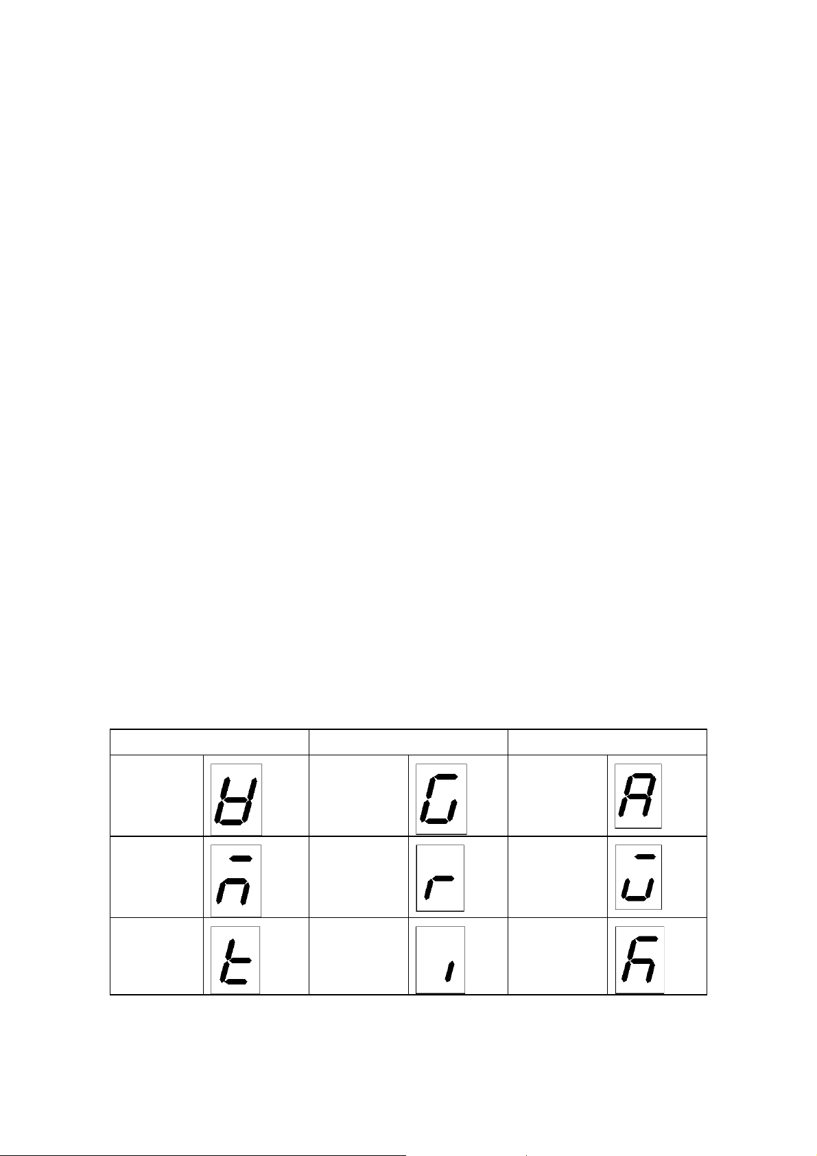
Indication of Characters
The control panel of Model High-Tech TV Programmable Controller uses 7-segment
light emitting diode (LED) to show alphanumeric characters 04 its d splay. This 7segment LED naturally has its limitation in expressing individual characters. Please
take note that the alphabetical characters of 'W." "m," t," "G," "r," "i," "A,"V and k"
are expressed by the substitutes below.
Character Indication Character Indication Character Indication
W G A
m
t i k
r
V
2
Page 5

Explanation of Character on the display
The oven has the controller with the 4-digit LED display.
The meaning of Character on the display is as follows:
Capital
Capital Character
CapitalCapital
A accumulation Integrated time
B beep Alarm sound setting mode
Character Meaning of Abbreviation
CharacterCharacter
Meaning of Abbreviation Meaning of Character on the display
Meaning of AbbreviationMeaning of Abbreviation
Meaning of Character on the display
Meaning of Character on the displayMeaning of Character on the display
C
D delete program Deleting a program
E end Setting mode for program end
F
H hold Hold funct ion m ode
L lock Panel locking mode
M
O off Make a function inactive
P program ## Program number
clock Setting of the date and the hour
door The open door
display Sub display switching mode
error ## Error code ##
fan fan
f. wt (Forced wait) Forced wait state after the power
restoration
fn. ## Fan condition of Segment ##
hr. mn (hour. minute) Setting of time (hour, minute)
mn. dy (month. day) Setting of the date (month and day)
on Make a function active
program Program mode
program, segment Ongoing program and ongoing segment
R repeat count Repeat frequency setting mode
repeat Repeat command mode
rest time Rest for remaining time
ramp level Ramp level of Segment ## (Desired set
temperature)
repeat start Repeat start segment setting mode
ramp time Ramp time of Segment ##
(Time required to reach the ramp level)
real (real time) The hour
r. tim (real time) the hour
3
Page 6
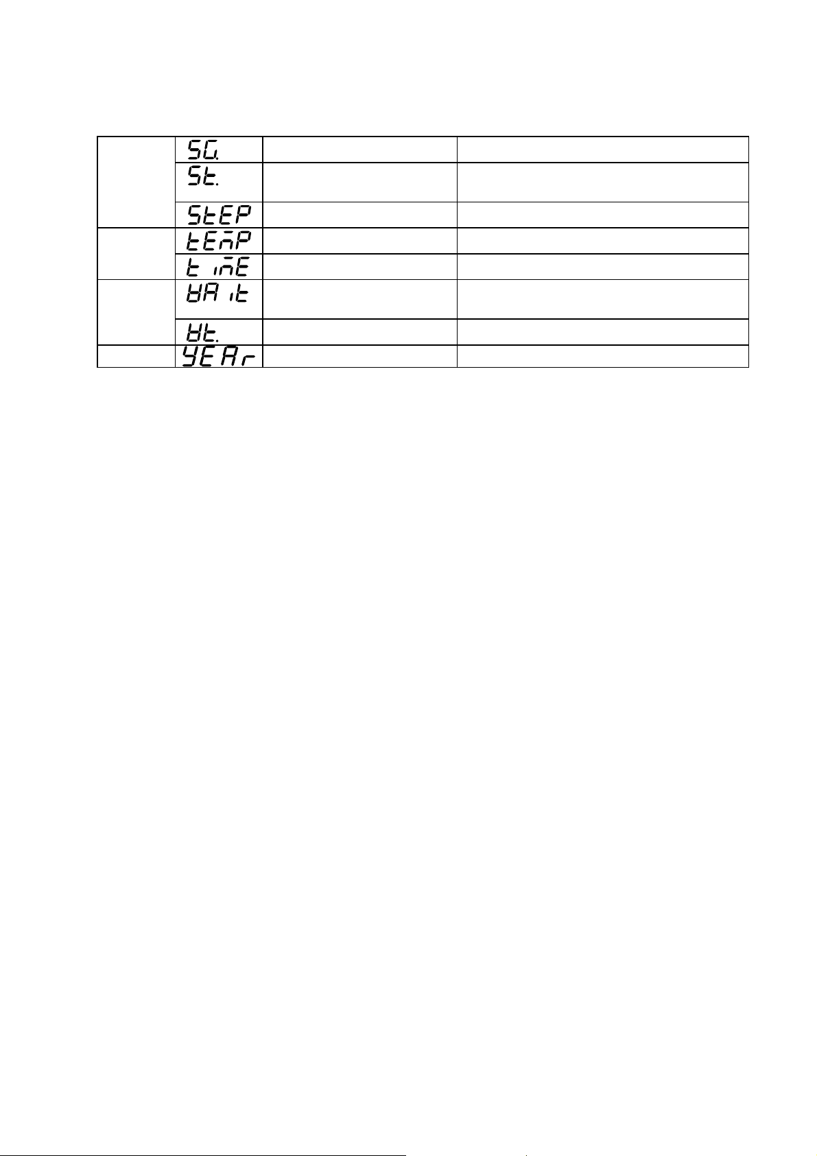
S
T temp Temperature mode
W wait Wait function (Keep the operation until
segment Segment number
soak time Soak time of Segment ##
(Holding time of the ramp level)
step Not in Ramp Operation
time Time mode
the desired temperature is achieved)
wait ## Wait function of Segment ##
Y
year the Christian era
4
Page 7

2. INPUTTING, EDITION AND DELETING PROGRAMS
2.1 Program Composition
A program is a combination of segments and repeat commands, in which ramp time,
ramp level, repeat frequency, end segment and other parameters should be preset.
[Segment]
Fig 2.1 shows the concept of a segment. Temperature and time patterns of a segment
are determined by the 3 basic parameters below.
Ramp level : Desired temperature
Ramp time : Time required to achieve the preset ramp level
Soak time : Time to hold the ramp level
Fig. 2.1: Concept of A Segment
In Section (① of Fig. 2.1~ temperature varies at a fixed gradient rate toward the
desired temperature set as the ramp level . After reaching the ramp level , temperature
is kept in Section② of Fig 2.1 for the time preset as the soak time. These sections of
and② compose a segment.
If you want to vary the temperature in Section① on a step (for full-power increase or
decrease), instead of a faced gradient rate, set for the ramp time. Fig. 2.2
shows the pattern of a step variation of the ramp time.
5
①
Page 8

Fig. 2.2: Step Variation of Ramp Time
The soak time is set at zero (0) for a s egment with only gradient-operation, wh ile the
ramp time is set at zero (0) for a segment with only fixed -value operation. Figure 2.3
shows a connected pattern of these 2 segments. In this figure, Section (4) is a segment
only with the soak time set at zero (0).
Fig. 2.3: Connection of Segmen4
Attribute Parameters of Segments
Attribute Parameters of Segments
■■■■
Attribute Parameters of Segments Attribute Parameters of Segments
In addition to the three basic parameters discussed above, you may preset the following
parameters.
6
Page 9

Wait Function ON/OFF: This function temporarily suspends counting time of the
program operation when influence of loads in the chamber or external disturbance such
as door operation has the chamber temperature failed in achieving the preset desired
temperature until the chamber temperature reaches the preset value. You may either
turn ON or OFF the function.
7
Page 10

Fan Revolution
Fan Revolution: You may preset the revolution of the internal agitation fan in the
Fan RevolutionFan Revolution
range from 1 (low speed) to 10 (high speed). See the operating instructions of your
system for the fan revolution (rpm), which varies with systems.
If your system cannot control the fan revolution, the programmable controller
automatically skips this functi on. If your system is equipped with optional automatic
damper controller, you may preset the damper aperture at 5 different levels.
End Segment
End Segment :When you want to complete programming, input "End" in the ramp
End SegmentEnd Segment
time, which creates the end segment. You may preset the fan controller at ON/OFF or
one of its 10 levels as a parameter of the end segment.
Hold
Hold: If you preset
HoldHold
in the soak time ,the program continues the fixed-value
operation thereafter
hours) on the display.
Note
Note: Model High-Tech IV Programmable Controller allows you to compose a program
NoteNote
of maximum 16 segments, which can be divided to make several different programs.
[Repeat Command]
[Repeat Command]
[Repeat Command][Repeat Command]
Repeat Command allows you to repeat a series of segments as many time as yon wan t.
This command is composed of 2 parameters; Repeat Start Segment and Repeat
Frequency.
Repeat Start Segment: Program repeats the section between the segment designated
as the repeat start segment and the segment immediately before the repeat start
segment.
Note
Note: (1) Repeat Command works for only the segments that were input and preset
NoteNote
before the command. In other words, you cannot repeat the segmen4 which
you preset after the repeat command.
appears next to a time setting of (999
(2) You cannot preset the nesting of a repeat command, which means to insert a
repeat command into the existing repeat command , as sh own in F ig. 2.4.1. It
is also impossible, as shown in Fig. 2.4.2, to preset a repeat command across
the existing repeat command.
8
Page 11
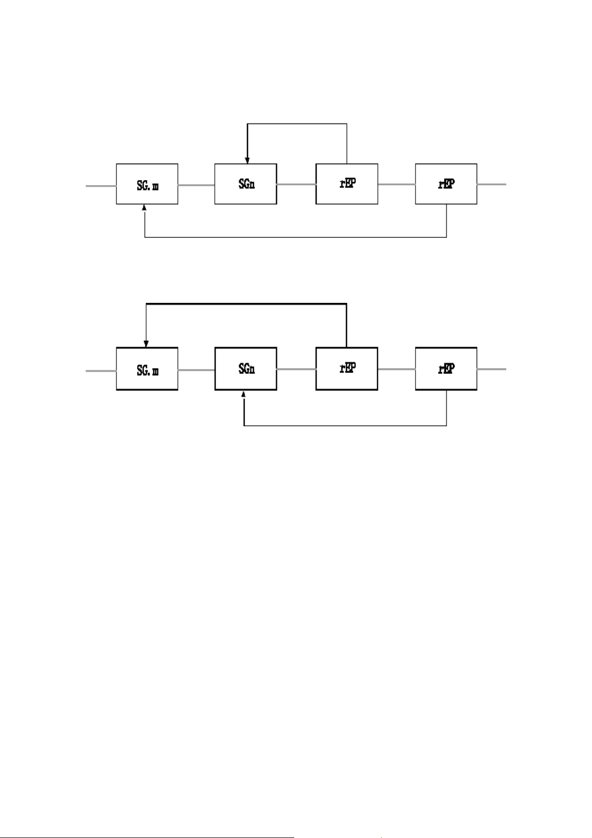
Fig.2.4.1:Nesting of a Repeat Command
Fig.2.4.2:Cross Setting of Repeat Commands
Repeat frequency
Repeat frequency :You may preset Repeat Frequency in the range from 1 to 9999
Repeat frequencyRepeat frequency
times. If you set the repeat frequenc y at zero(0),wh i ch means endless repetition of th e
segments ,the program continues repeat operation until it is fo rced t o st op.
9
Page 12

Indication of the rest of the repeat count
Indication of the rest of the repeat count
Indication of the rest of the repeat countIndication of the rest of the repeat count
The rest of the repeat frequency including the ongoing segment can be shown on the
sub display by using the DISPLAY key while performing the repeat command of
the program operation.
[Operation Procedure]
[Operation Procedure]
[Operation Procedure][Operation Procedure]
Key Operation Main Display Sub Display Explanation
The repeat operation is on : Ex. While performing the repeat operation the segment 2 to 3 of the
program 2
Push the Display
key several times
Push either ▲ key
or ▼ key
It shows the present
measured
temperature
It shows the present
measured
temperature
(Ex.: Indication of
the execution
segment)
(Ex.: Indication of
the execution
segment)
↑↓
alternately
(Ex.: Indication of
the remaining repeat
frequency)
Shown
Push the display key and
make the sub display shown
the execution segment.
The sub display shows the
ongoing program number at
the left double-digit and the
ongoing segment at the
right double-digit.
When performing this
operation while running the
repeat operation, the dot
point of the LSB (the right
most digit) flashes.
The remaining repeat
frequency can be shown on
the sub display by pushing
the ▲ key or ▼key while the
dot point located at the
corner of the below to the
right of the segment number
is flashing ( during running
the repeat operation.)
The remaining repeat
frequency shown at this
time includes the ongoing
segment.
When you perform the
repeat operation infinitely
(the setting of the repeat
frequency is 0), 0 is shown
on the sub display.
10
Page 13

2.2 Inputting Programs
In this paragraph , you will learn how to input the program shown in Fig.2.5 as an
example into Program No.2.
Fig.2.5:Sample Program
11
Page 14

Note: In the tables below, hollow alphanumeric characters mean that they
Note: In the tables below, hollow alphanumeric characters mean that they
Note: In the tables below, hollow alphanumeric characters mean that theyNote: In the tables below, hollow alphanumeric characters mean that they
are flashing on the corresponding display.
are flashing on the corresponding display.
are flashing on the corresponding display.are flashing on the corresponding display.
[Setting Program Number]
[Setting Program Number]
[Setting Program Number][Setting Program Number]
Key
Operation
MODE key
and then
push either
key or ▼ key
key,
Push ▲ key.
[Setting Segment 1]
[Setting Segment 1]
[Setting Segment 1][Setting Segment 1]
Main
Display
▲
e.g., e.g.,Push ENTER
Sub
Display
e.g.,Push the
Explanation
Left 2 digits: Number of the existing
programs
Right 2 digits Remaining memory size (%)
Activates Program input & Edit mode.
Main: Indicates Program No. 1.
Left 2 digits: Memory size of Program No. 1
Right 2 digits: Remaining memory size
Same as above.
The slob display shows that the memory size
of Program No. 2 is zero (O) or that Program
No. 2 has not been programmed.
Key
Operation
key.
Push ENTER
key.
Main
Display
Approx. 1 second laterPush ENTER
Approx. I second later
e. g
Sub
Display
Explanation
Activates Program input mode for .
Requesting to input Ramp Time 1
of Segment 1. Push ▲ or ▼ key
when you want to switch Prom STEP to real
time. In this example, you are working on a
step operation so that you do not need to
change the indication.
The main display stops flashing and keeps
lighting the indication , notifying that Ramp
Time 1 was set.
Requesting to input the temperature of
Ramp Level 1
12
Page 15

Push
▲
or
▼
Push ▲or ▼ key to show a desired
key and ENTER
key.
Push
key and ENTER
key.
▲
or
▼
↓
(Lighting)
Approx. l second later
e. g.,
(Lighting)
Approx. 1 second later
temperature of 150_C and push ENTER
key to accept it as Ramp Level 1. The
main display changes from flashing to
lighting,
Requesting to input Soak Time 1 of
Segment 1.
Push ▲or▼ s key to show a desired
soak time of 1 hour 20 minutes and
push ENTER key to accept it as Soak
Time 1. The main display changes from
flashing to lighting.
Push ▲or ▼ key to turn on or off Wait
Function 1. In this example, you are
working on a step operation so that you
do not need to change the indication.
Push ENTER
key,
Approx. 1 second later Requesting to input Fan Revolution.
push ENTER
key.
You have finished setting Segment 1.
The main, display changes from
flashing to lighting, notifying that Wit
Function 1 was set.
Push ▲ or ▼ key to set a level of Fan
Revolution in the range from Level 10
(fast) to Level 1 (slow). Default is Level
10. In this example, you accept a fan
revolution of Level 10.
The main display changes from flashing
to lighting, notifying that the fan
revolution of Level 10 was set.
13
Page 16

[SettingSegment2]
[SettingSegment2]
[SettingSegment2][SettingSegment2]
Key Operation Main
Display
Push ENTER
Approx. 1 second later
key,
↓↓
Sub
Display
Explanation
Activates Input mode for Segment 2.
Left 2 digits. Program number you are
working on.
Right 2 digits: Remaining memory size
Requesting to input Ramp Time 2
of Segment 2.
Input and preset the following parameters for this example in the same manner as
Segment 1.
:20 minutes
: 200
℃
: 30 minutes
: ON
: 10
[Setting Segment 3]
Input and preset the following parameters in She same manner as above.
: StEP
: 150
℃
: 0 minute (This is a segment of only the gradient operation.)
: OFF
: 10
You have finished setting Segment 2 and 3.
14
Page 17

[Setting a Repeat Command]
[Setting a Repeat Command]
[Setting a Repeat Command][Setting a Repeat Command]
hey
Operation
Main
Display
Sub Display Explanation
Approx. 1 second later
Push ▲ or
key.
▼
Push
↓
ENTER
key.
↓
The main display shows that the
programmable controller is ready for
inputting Segment 4.
Push▲ or ▼ key to change the controller
to the input mode of Repeat Command. The
main display flashes
(Repeat).
Requesting to input the number of Repeat
Start Segment
Push ▲ or
key and
▼
ENTER
key.
↓
Lighting
Push ▲ or ▼ key to show the desired
repeat start segment number of 2 and push
ENTER key to accept it. The main display
changes from flashing to lighting.
↓↓
input the repeat frequency. Default is set at
1.
Push▲ or
key and
▼
↓
ENTER
key.
You have finished setting Repeat Command..
You have finished setting Repeat Command..
You have finished setting Repeat Command..You have finished setting Repeat Command..
[Setting Segment 4]
[Setting Segment 4]
[Setting Segment 4][Setting Segment 4]
Key
Operation
Push
Lighting
Main
Display
Sub
Display
Approx. 1 second later
Push ▲or ▼ key to show a repeat frequency
of 2 and push ENTER key to accept it. The
main display changes from flashing to
lighting.
Explanation
Activates Input mode for Segment 4 when
.
(Repeat Count): Requesting to
ENTER
key.
↓↓
you accept the repeat command.
Requesting to input Ramp Time 4
of Segment 4.
Input and preset the following parameters in the same manner as previous segments.
: 0 minute (This is a segment of only the fixed value operation )
: 150
℃
: 50 minutes
: ON
: 10
You have finished setting Segment 4.
You have finished setting Segment 4.
You have finished setting Segment 4.You have finished setting Segment 4.
15
Page 18

[Inputting and Setting End Segmen t]
[Inputting and Setting End Segmen t]
[Inputting and Setting End Segmen t][Inp utti n g an d Setti n g E nd Segment]
Key
Operation
Push ENTER
key.
Push ▲or
▼
key
Push ENTER
key
Push ▲or
▼
key.
key.
Main
Display
Sub
Display
↓↓
↓
Approx. 1 second laterPush ENTER
Explanation
Activates Input mode for Segment 5.
Requesting to input Ramp Time5
(
) of Segment 5.
Push ▲ or ▼ key to change to Program
Input mode for End Segm e nt.
Requesting to turn on or off the fan or input
its revolution level.
Push A or t key to change the setting. In
this example, turn off the fan.
Push ENTER key to accept the setting of
the fan, This completes all the setti ngs for
Program No. 2. The displays return to thei r
initial indications of Program Input a Edit
mode.
16
Page 19

2.3 Editing Programs
Model High-Tech IV Programmable Controller supports Edit function of only
Segment parameters; and
・
Repeat parameters
・
or editing programs. Take note that the programmable controller does not support
Delete of repeat command and Insert of new segments or a new repeat command.
In this paragraph, you will edit Segment 3 of Program No. 2
which is composed of the following segments and a repeat command.
Key Operation Main
Display
Push the
MODE key
and then
push either
key or ▼key
Push ENTER
key.
Push▲or▼key
▲
e
.g.,
↓↓
Sub
Display
.g.,
e
.g.,
e
.g.,
e
Explanation
Left 2 digits: Number of the existing
programs
Right 2 digits: Remaining memory size (%)
Activates Program Input & Edit mode.
Push ▲ or ▼ key to show the program
number you want to edit on the main display.
Left 2 digits: Memory size of Program No. 2
Right 2 digits: Remaining memory size
in Fig. 2.6,
Push ENTER
key.
Push
key.
▲
or
▼
The main display Rashes the first segment
number of the program.
Left 2 digits: Program number you are
working on.
Right 2 digits: Remaining memory size (%)
Every time you push A or Y key, the main
display scrolls the segments of the program
in the preset sequence. In this example, you
are going to edit Segment 3
which should be shown on the main display.
17
,
Page 20

Push ENTER
Indicates that the ramp time of Segment S
key.
is set at the step operation. Change it to
the gradient operation with a ramp time
the gradient operation with a ramp time
the gradient operation with a ramp timethe gradient operation with a ramp time
of 45 minutes.
of 45 minutes.
of 45 minutes.of 45 minutes.
Change it to
Change it toChange it to
Input and preset the following parameters in the same manner as discussed in
"inputting Programs."
: 45 minutes
: 150
℃
: o minutes (This is a s egment of only the gradi ent operation.)
: ON
: 10
You have changed the parameters with asterisks. For the other parameters you do not
change, push only ENTER key.
Whenever you have finished editing a
Whenever you have finished editing a
Whenever you have finished editing aWhenever you have finished editing a
parameter, the displays return to s h ow
parameter, the displays return to s h ow
parameter, the displays return to s h owparameter, the displays return to s h ow
the initial indications of Program Edit
the initial indications of Program Edit
the initial indications of Program Editthe initial indications of Program Edit
mode.
mode.
mode.mode.
↓
If you leave them for about 10 seconds,
the programmable controller understands
that you have finished editing the
program and returns to the displays
shown immediately before you pushed
MODE key.
18
Page 21

2.4 Deleting Programs
You can delete the programs not in use any longer from the programmable controller.
Take note that on Program Delete mode, you cannot check the contents of the program
you are going to delete.
In this paragraph, you v ill learn how to delete Program No. 1
Key
Operation
Push the
MODE key
and then
push either
key or
▲
key
Push
ENTER key.
▼
Main
Display
Sub
Display
Explanation
Push MODE key several times to flash
(Delete Program) on the man
display.
Left 2 digits: Number of the existing
programs
Right 2 digits: Remaining memory size (%)
Activates Program Delete mode.
The main display shows the smallest
number of the existing programs.
Every time you push ▲ or ▼ key, the
main display scrolls the program number
in sequence. In this example/ you are going
to delete Program No. 1, so that don't touch
s and t keys.
Push
ENTER key.
(Lighting)
Approx, 1 second later
Pushing ENTER key deletes Program No.
Pushing ENTER key deletes Program No.
Pushing ENTER key deletes Program No.Pushing ENTER key deletes Program No.
1, and the main display returns to the
1, and the main display returns to the
1, and the main display returns to the1, and the main display returns to the
initial indication of Program Delete mode.
initial indication of Program Delete mode.
initial indication of Program Delete mode.initial indication of Program Delete mode.
Deleting Program No. 1 (with a memory
size of 43%) reduces the number of the
existing programs to 1, and the remaining
memory size to 74%.
19
Page 22

Temporary Suspension of Program Operation
Temporary Suspension of Program Operation
Temporary Suspension of Program OperationTemporary Suspension of Program Operation
Temporary suspension of program operation means to stop the program timer and
temporarily keep the programmable controller at the status of ready-for-operation.
During the suspension, the programmable controller shuts off power supply to heaters
and does not regulate chamber temperature.
[Suspending Program Operation Temporarily]
[Suspending Program Operation Temporarily]
[Suspending Program Operation Temporarily][Suspending Program Operation Temporarily]
Key
Operatio
Main
Display
Sub Display Explanation
n
Push
Operatio
If you push Operation Menu key during the
program operations the main display shows
n Menu
key
(Pause) while the sub display
shows the ongoing program number. When
you want to cancel Temporary Suspension of
Program Operation, leave the programmable
controller for 20 seconds or push ESC key.
Push
Suspends program operation temporarily.
Suspends program operation temporarily.
Suspends program operation temporarily.Suspend s p rogram operation temp orarily.
ENTER
key.
(Lighting)
Approx. 1 second later
The main display shows chamber
temperature, while the sub display
alternately shows , and the program number
.,
e.g
↑↓
[Restarting Program Operation]
[Restarting Program Operation]
[Restarting Program Operation][Restarting Program Operation]
Alternate
indicator.
(left 2 digits)
segment number (right 2 digits).
Ready indicator lamp Rashes on the
operation monitor.
and the ongoing
Push Operation Menu key and operation starts again automatically. If chamber
temperature deviated from the preset temperature during the suspension of operation,
the sub display flashes its indication. When chamber temperature reaches the desired
temperature, the operation timer starts again and the sub d isplay shows the correct
temperature.
Important
Important
ImportantImportant
Program input, Edit and Delete modes can be activated only during the program
operation, and they do not work in the fixed-value operation and the automatic
star/stop operation. These modes can work when you have pushed Operation Menu key
at the status of ready-for -operation, including temporary suspension of program
operation. When the programmable controller is on the mode which cannot execute
Program input, Edit and Delete, pushing MODE key skips the indication of these
modes.
20
Page 23

3. INPUTTNG AND SETTING FUNCTIONS
↑
↓
You can add a variety of functions by using MODE key. This section discusses the
inputting and setting functions, which are common to all Yamato Scientific's machinery
and equipment. For setting the functions particular to your system, see the operating
instructions of the system. If your system does not support certain functions, pushing
MODE key simply skips those functions, which are not shown on the displays.
3.1 Switching between Time and Period
Starting time of the automatic state operation and the program operation, and ending
time of automatic stop operation can be designated by either time or period-of
operation, If you set them by time, the sub display shows it at the upper left corner.
In this paragraph, you will learn how to change the setting from time to period of
operation.
[Procedure]
[Procedure]
[Procedure][Procedure]
Key
Operation
Push the
MODE key
and then
push either
key or
▲
key
Push ENTER
key.
Push ▲or
key.
▼
▼
Main
Display
(Lighting)
Approx. l second later
Alternate
indication
Sub
Display
Explanation
Push MODE key several times to
show
display, The sub display shows the present
time.
Activates Time/Period Switching mode.
or XXX hours)
Push ▲ or ▼ key to show
the main display.
(Time) on the main
:Time (XX o'clock XX minutes)
:Interval (E hours XX minutes
on
21
Page 24

Accepts the change of the setting from time
Push
ENTER
key.
Note: Time is default setting. When you are setting the operation parameters, you
cannot switch this setting.
(Lighting)
Approx. 1 second later
The displays return to
their initial indications
shown immediately before
you pushed MODE key.
Accepts the change of the setting from time
Accepts the change of the setting from timeAccepts the change of the setting from time
to period of operation.
to period of operation.
to period of operation.to period of operation.
22
Page 25

3.2 Setting and Releasing Panel Key Lock
Panel Key Lock deactivates the eight keys on the control panel, except for indication
Switching key. With this special function, you can prevent accidental or unauthorized
key operation ashen the programmable controller is in service.
[Setting Panel Key Lock]
[Setting Panel Key Lock]
[Setting Panel Key Lock][Setting Panel Key Lock]
Key
Operation
Push the
MODE key
and then
push either
key or
▲
key
Push
ENTER
key.
Main
Display
▼
(Lighting)
Approx. 1 second later
Sub
Display
Explanation
Push MODE key several times to show
(Lock) on the main display. The
display shows the present setting
Activates Panel Key Lock Set/Release mode.
Activates Panel Key Lock Set/Release mode.
Activates Panel Key Lock Set/Release mode.Activates Panel Key Lock Set/Release mode.
Push ▲ or
key.
▼
↑
↓
Alternate
indication
:Releases Panel Key Lock.
: Sets Panel Key Lock
When you want to lock the panel keys, push
or ▼ key to show
▲
on the
main display
Accept the setting of Panel Key L ock.
Push
Accept the setting of Panel Key L ock.
Accept the setting of Panel Key L ock.Accept the setting of Panel Key L ock.
ENTER
key.
(Lighting)
Approx. 1 second later
The displays return to
The displays return to their initial
indications shown immediately before you
pushed MODE key.
their initial indications
shown immediately
before you pushed MODE
key.
Note: Panel Key Lock ON is default setting When you are setting the operation
parameters, you cannot switch this setting.
[Releasing Panel Key Lock]
[Releasing Panel Key Lock]
[Releasing Panel Key Lock][Releasing Panel Key Lock]
Push MODE key to activate Panel Key Lock Set/Release mode, and switch OFF
(
) the lock
Note. When the panel key lock is turned on, MODE key skips all the modes except for
Panel Key Lock Set/Releasing mode.
23
Page 26

3.3 Turning ON and OFF Buzzer Sound
If something abnormal happens on your system, all the indicator lamps including
alarm indicator lamps start flashing, the main display shows the present chamber
temperature and the sub display shows the error code of the abnormal condition. You
can choose to activate or deactivate buzzer sound when your system is in trouble.
In this paragraph, you will learn how to turn on the buzz er sound.
[Procedure]
[Procedure]
[Procedure][Procedure]
Key
Operation
Push the
MODE key
and then
push either
key or
▲
▼
key
Push
ENTER
key.
Main
Display
(Lighting)
Approx. 1 second later
Sub
Display
.,
e.g
Explanation
Push MODE key several times to show
(Beep) on the main display. The
sub display shows the present setting.
Activates Buzzer Sound ON/OF F mod e
Activates Buzzer Sound ON/OF F mod e
Activates Buzzer Sound ON/OF F mod eActivates Buzzer Sound ON/OF F mod e
Push ▲ or
key.
▼
↑
Alternate
↓
indication
When you want to turn on the buzzer sound,
push ▲or ▼ key to show
the main display
Push
ENTER
key
.
(Lighting)
Approx. 1 second later
Accepts the setting of Buzzer Sound .
Accepts the setting of Buzzer Sound .
Accepts the setting of Buzzer Sound .Accepts the setting of Buzzer Sound .
The displays return to
their initial indications
shown immediately
before you pushed MODE
key.
Note: Buzzer Sound
Note: Buzzer Sound is default setting.
Note: Buzzer Sound Note: Buzzer Sound
is default setting.
is default setting. is default setting.
: Deactivates buzzer Soured
:Activates buzzer sound.
on
24
Page 27

3.4 Indication of Integrating Operation Time
This function accumulates the op eration ti me when P ower key is turn ed on. Maxi mum
accumulation of time is 49,999 hours, which cannot be reset. Accumulated operation
time provides useful information when you determine the timing of maintenance.
In this paragraph, you will learn how to show the accumulat ed operat ion t im e.
[Procedure]
[Procedure]
[Procedure][Procedure]
(1) Push the MODE key and then push either ▲ key or ▼ key
(2) Push the MODE key and then push either ▲key or ▼ key to show
(Accumulation) on the main displ ay. T h e s ub d i s p l ay s h ows th e accu mul a ted
operation time at present (in the unit of hours),
Note: You do not need to push ENTER key, because this function only shows the
accumulated operation time. In this functi on, ENTER key and ▲and ▼ keys do not
work.
(3) When you want to cancel the function, push ESC key or leave the programmable
controller for 20 seconds, The displays return to their indications shown immediately
before you pushed MODE key.
[Expression of Accumulated Operation Time]
[Expression of Accumulated Operation Time]
[Expression of Accumulated Operation Time][Expression of Accumulated Operation Time]
When the accumulated operation time exceeds 9999 hours 59 minutes, the sub display
goes back to 0 (zero) and starts emulating ti me again. Decimal p oint al so moves to the
left by one digit at every operation time of 10,000 hours.
Figure① shows an accumulated operation time of 10,050 hours.
In the same manner, ② means 20,050 hours, ③ 30,050 hours and
40,050 hours
④
①
②
③
④
25
Page 28

3.5 Setting Date and Time
The timer clock built in Model High-Tech IV Programmable Controller has been
calibrated at the standard time in our factory. However, you still need to adjust it
periodically to make sure of its correct time indication in your operating environment.
In this paragraph, you will learn how to calibrate the built- in tim er clock .
Note: The built-in timer clock causes an daily error of 12 seconds at a working
temperature of 25℃.
[Procedure]
[Procedure]
[Procedure][Procedure]
Key
Operation
Push the
MODE key
and then
push either
key or
▲
key
push ENTER
key.
Push ENTER
key.
▼
Main
Display
Sub
Display
.,
e.g
Explanation
Push MODE key several times to
show
display. The sub display show j the
accumulated operation time in the order of
year, date and time at an interval of 2
seconds.
Activates Date & Time Set mode.
The sub display shows
and the main display flashes the present
data.
push ▲ or ▼ key to set the correct year.
In about 1 second, Date Set mode is
activated. The sub display shows
(Clock) on the main
(Year)
(Month and Day) and the main
display flashes the present data. Push ▲or
key to set the correct date.
▼
Push ENTER
key.
Approx.1 second laterPush ENTER
key.
Note:
Note: if you want to cancel the calibration of Date & Time, push ESC key or leave
Note:Note:
the programmable controller for 20 seconds. Date & Time Setting Function works
only when the programmable controller is ready for operation with Operation
Menu selected or after operation.
The displays return to
their initial indications
shown immediately
before you pushed MODE
key.
In about 1 second, Time Set mode is
activated. The sub display shows
(Hours and Minutes) and the
main display flashes the present data,
Push ▲or ▼ key to set the correct time.
Accepts the setting of Date & Time.
26
Page 29

3.6 Hold Function
3.6 Hold Function
3.6 Hold Function3.6 Hold Function
Hold function is the one of functions that the HitecⅣcontroller supports by using the
MODE key.
It can work only if the setting time of the operation start time of the Auto-Start
operation and the Program operation and the operation stop time are not set in
hours but in a period of time.
General Description of the Hold Function
General Description of the Hold Function
General Description of the Hold FunctionGeneral Description of the Hold Function
Once the Hold Function is on, i mmediately the HitecⅣcontroller stops the built-in
timer and keeps the condition. The definite examples are shown below.
1. When the Hold Function activated while the unit is in standby condition of starting
operation, the waiting time to start is extended by a period of time when the Hold
Function was on
2. When the Hold Function activated while performing the fixed gradient rate operation
toward the desired temperature, the controller stops the gradient operation and
changes to the fixed temperature operation to keep the internal target temperature of
the controller at the point of time. ( The internal target temperature is not always same
as the ramp level in the program segment) Once the Hold Function is off, the
controller resumes performing the gradient operation that had been performed just
before the Hold Function was on.
3. When the Hold Function activated while performing the gradient operation with full
power , the controll er changes to the fi xed temperature operat ion to keep the chamb er at
the ramp level in the program segment after reaching the ramp level (the desired
temperature)
4. When the Hold Func tion activated while keepin g the chamber at the ramp lev el, the
setting soak time in the Auto-Stop operation and the Program operation are extended
by a period of time when the Hold Function was on
5. When you change a certain ongoing operation to the other operation by pushing
the MENU key with the Hold Function is on, the Hold Function is automatically
released at the point of time when the operation is changed.
27
Page 30

Operating procedure
Operating procedure
Operating procedureOperating procedure
Key Operation Main Display Sub Display Explanation
Push the MODE
key and then
push either▲key
or ▼ key
Push the ENTER
key
Push either
key or ▼ key
▲
Approx. 1 second later
Blink (Hold) on the main
display.
The sub display shows the present
setting.
Activates Hold Function Setting
Activates Hold Function Setting
Activates Hold Function SettingActivates Hold Function Setting
mode.
mode.
mode.mode.
:Hold function is off (inactive)
:Hold function is on (activate)
The main display blinks the present state
of Hold mode and sub display shows
: Releases Hold state
: Sets Hold state
Choose if you want to bring
the unit to the Hold state.
Push the ENTER
key
Approx. 1 second later
It shows the
present
measured
temperature.
Hold Function was set to when the unit is shipped from the factory.
Accepts the setting of Hold state
Accepts the setting of Hold state
Accepts the setting of Hold stateAccepts the setting of Hold state
The main display shows the present
measured temperature
and the sub display blinks in
the Hold state.
The present set temperature can be
shown on the sub display only for 10
seconds by pushing the DISPLAY key.
28
Page 31

3.7 Communication lock out function
This function makes the communication between the PC and HitecⅣcontroller
enable / disable.
If this function is activated during communicating with a host computer, the
controller closes the communication
Operating Procedure
Operating Procedure
Operating ProcedureOperating Procedure
Key Operation Main Display Sub Display Explanation
Push the MODE
key and then
push either
key or ▼ key
Push the ENTER
key
Push either
key or ▼ key
▲
▲
Approx. 1 second later
Blink (Communication Lockout) on the main display.
The sub display shows the present
setting.
Activates Communication Lock-out
Activates Communication Lock-out
Activates Communication Lock-outActivates Communication Lock-out
Function setting and releasing mode
Function setting and releasing mode
Function setting and releasing modeFunction setting and releasing mode
:Communication with PC is
enable.
: Communication with PC is
disable.
: Releases Communication
Lock-out state
: Sets Communication Lock-
out state
Choose if you want to bring
the unit to the Communication Lock-out
state.
Push the ENTER
key
Approx. 1 second later
Communication Lock-out Function was set to when the unit is shipped
from the factory.
29
Accepts the setting of Communication
Accepts the setting of Communication
Accepts the setting of CommunicationAccepts the setting of Communication
Lock-out.
Lock-out.
Lock-out.Lock-out.
Both displays return to the indicating
state just before you pushed the MODE
key when Communication Lock-out is on.
Page 32

Releasing the Communication Lock-out
Releasing the Communication Lock-out
Releasing the Communication Lock-outReleasing the Communication Lock-out
By pushing the MODE key while the C ommunication Lock-out function is on, Hitec
controller goes to the setting and releasing the Communication Lock-out mode,
Ⅳ
and then you can release the Communication Lock-out condition to choose ‘off’ by
pushing the ▲key or the ▼ key.
Precaution in handling
Precaution in handling
✻✻✻✻
Precaution in handlingPrecaution in handling
※
The remote operation cannot be performed while the Communication
The remote operation cannot be performed while the Communication
The remote operation cannot be performed while the CommunicationThe remote operation cannot be performed while the Communication
Lock-out function is on.
Lock-out function is on.
Lock-out function is on.Lock-out function is on.
※
The unit without the PC communication feature may show the
The unit without the PC communication feature may show the
The unit without the PC communication feature may show theThe unit without the PC communication feature may show the
indication of this function at its di splay by operating the MODE key.
indication of this function at its di splay by operating the MODE key.
indication of this function at its di splay by operating the MODE key.indication of this function at its display by operati ng the MODE key.
Setting does not bring any effective result.
Setting does not bring any effective result.
Setting does not bring any effective result.Setting does not bring any effective result.
✻✻✻✻
30
Page 33

4. SAFETY MEASURES AND PRECAUTIONS
This section discusses the safety measures provided for Model High-Tech IV
Programmable Controller, and the operational precautions of the controller and your
system regulated by the controller. See the operating instructions of your system,
which also describe safety measures and precautions.
4.1 POST Function
POST stands for Power On Self Test, which is a special function to check the
controller's microprocessor, memory, peripheral LSI's and peripheral circuits whenever
you turn on Power key. With this POST function, you can make sure that the controller
is free of serious troubles before starting operation.
If the function defects something abnormal, the sub display shows one of error codes
corresponded to the trouble from among error codes of
.
These error codes mainly indicates a trouble of electronic circuits If this is the case,
turn off the breaker and co ntact th e d eal er of your s ystem, Yama to Sci enti fic C D., L td.
or Yamato Engineering Co., Ltd. in your vicinity.
, and
4.2 Precautions
1) To prevent overheating, Model High-Tech IV Programmable Controller is equipped
with automatic attempering function In ad dition, some of our systems also have their
own attemperators in the circuit separated from the programmable controller.
However, when you are working on exothermic samples or supplying electricity to
samples to generate heat, those temperature regulating systems do not work
effectively.
When temperature goes up abnormally high, shut down power supply or take any other
appropriate measures Yamato Scientific is prep ared to modify your system to manage
such troubles.
2) In case of power failure, the programmable controller of the standard specifications
automatically resets itself and restarts operation when electric power becomes
available again. If you install the optional Restart Selector Function In the controller,
you can select either Automatic Reset or Manual Reset to restart operation after power
failure for a certain period of time.
31
Page 34

5. Behavior after Power Restoration
When having a blackout during operation, the controller resumes the following
operations after the power restoration.
5.1
5.1 When having a blackout during the program operation
When having a blackout during the program operation
5.15.1
When having a blackout during the program operation When having a blackout during the program operation
The controller automatically resume the program operation where it left at the
power shutdown. In case that the temperature inside the chamber is outside the
specified temperature range based on the setpoint temperature, the controller goes
to the FORECED WAIT STATE until the
temperature inside the chamber comes back to the specified temperature range.
When selecting the indication of the remaining time by pushing the Display key in
this condition, the sub display shows
The timer built-in the controller does not count a period of having a blackout as
running time.
5.2
5.2 When having a blackout during the Auto-Stop operation
When having a blackout during the Auto-Stop operation
5.25.2
When having a blackout during the Auto-Stop operation When having a blackout during the Auto-Stop operation
The controller automatically resume the Auto-Stop operation where it left at the
power shutdown. In case that the temperature inside the chamber is outside the
specified temperature range based on the setpoint temperature after the power
restoration, the controller goes to the FORECED WAIT STATE until the
temperature inside the chamber comes back to the specified temperature range.
When selecting the indication of the remaining time by pushing the Display key in
this condition, the sub display shows
In case that the operation stop time is set in a period of time, the timer built in the
controller does not count a period of a blackout as running time. On the contrary,
in case that the operation stop time is set in hours , the timer built in the controller
counts a period of a blackout as running time.
When the operation stop time reaches during a blackout, the controller stops
running just after the power restoration.
5.3
5.3 When having a blackout while the operation is in standby condition
When having a blackout while the operation is in standby condition
5.35.3
When having a blackout while the operation is in standby condition When having a blackout while the operation is in standby condition
In case that the operation start time is set in a period of time, the timer buil t in the
controller does not count a period of a blackout as standby time. On the contrary,
in case that the operation start time is set in hours , the timer built in the controller
counts a period of a blackout as standby time.
When the operation start time reaches during a blackout, the controller starts
running just after the power restoration.
.
.(Forced Wait)
5.4
5.4 When having a blackout during the Fixed temperature operation and a soak
When having a blackout during the Fixed temperature operation and a soak
5.45.4
When having a blackout during the Fixed temperature operation and a soak When having a blackout during the Fixed temperature operation and a soak
period of the Auto-Start operation
period of the Auto-Start operation
period of the Auto-Start operationperiod of the Auto-Start operation
The controller resumes running toward to the preset temperature after the power
restoration.
32
 Loading...