

Page 1

Heating Block
Type HF100/200
First Edition
Yamato Scientific Co., Ltd.
Page 2

Page 3

Contents
1.Name and Function of Components ..................................................... 1
Main body ........................................................................... 1
Operation panel ...................................................................... 2
Description of characters displayed in the temperature controller ............................ 3
2.Operation Method..................................................................... 4
Preparation .......................................................................... 4
List of operation modes and functions ................................................... 5
Fixed-value operation(continuous operation)mode ...................................... 6
Quick auto-stop operation.............................................................. 8
Auto-stop operation .................................................................. 11
Auto-start operation.................................................................. 15
Other functions...................................................................... 19
3. In Case of Trouble................................................................... 23
Error display ........................................................................ 23
Troubleshooting guide................................................................23
4. Specifications....................................................................... 24
5. Wiring Diagram ..................................................................... 25
Page 4

Page 5
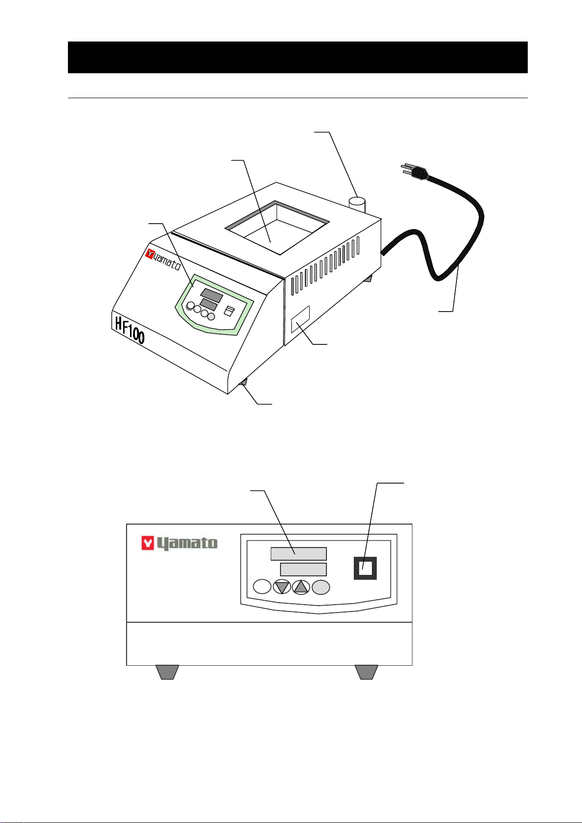
1.Name and Function of Components
Aluminum block mounting portion
(Aluminum block available
separately)
Operation panel
Hand grip for aluminum block
Main body
Power cord
Serial No. plate
Temperature controller
Leg
Power switch
(circuit breaker)
Heating Block
HF100
1
Page 6
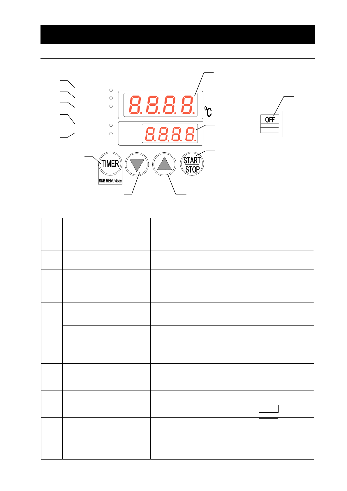
1. Name and Function of Components
Operation panel
⑪
⑩
⑨
⑧
⑦
Fixed Temp.
Auto Stop
Auto Start
Heater
Alarm
⑥
Measured Temp. POWER
Set Temp.
①
⑫
②
③
No. Name Function
① Measured temperature display Displays the bath measured temperature, set mode
② Set temperature display Displays the set temperature, timer set time, remaining
③ Start/stop key Used to start/stop operation.
④ ▲ key Used to increment the set value.
⑤ ▼ key Used to decrement the set value.
Timer key Used to set the timer and sub-menu. ⑥
Sub-menu selector key Keep pressing the key for four seconds, and such
⑦ Alarm lamp Flashes in case of alarm
⑤
character, alarm temperature.
timer-operation time, character to set the sub-menu.
Keep pressing for one second.
functions as key lock, calibration offset temperature
setting, and power failure compensation selection can be
set.
④
⑧ Heater lamp ON when the heater output is ON
⑨ Fixed-value operation lamp ON during the fixed-value operation
⑩ Auto start operation lamp ON during auto-start operation with the TIMER key
⑪ Auto stop operation lamp ON during auto-stop operation with the TIMER key
⑫ Power switch ON to turn ON system power supply and OFF to turn OFF
system power supply. Circuit breaker to turn OFF power
supply at over-current
2
Page 7
1. Names and functions of parts
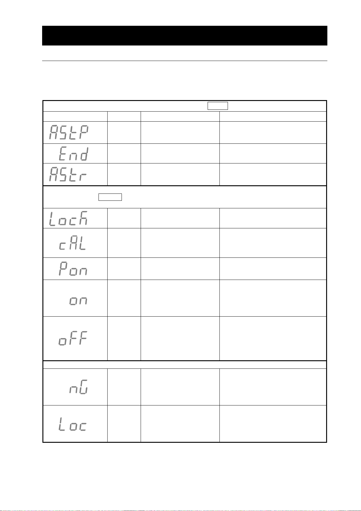
Description of characters displayed in the temperature controller
The controller uses a display of 7-segment LED. Characters to display operation functions are
indicated in the “Measured Temp.” screen.
Character displays and corresponding meanings are described below.
Auto-stop or Auto-start operation can be selected with the TIMER key.
Character Identifier Name Meaning
Timer menu mode
AStP
End Time-up
AStr
Function settings as follows can be made from the sub-menu.
Keep pressing the TIMER key for four seconds, and the mode changes to the sub-menu mode.
To return to the original screen, keep pressing the TIMER key.
LocK
cAL
Pon
on
off
Two characters to indicate that operation is not possible
nG Operation impossible
Loc
Timer setting mode
display
Timer menu mode
Timer setting mode
display
Sub-menu mode
Locked at fixed value
Sub-menu mode
Calibration offset
Sub-menu mode
Power failure
compensation selection
Sub-menu mode
Locking the setting
Power failure
compensation selection
auto reset
Sub-menu mode
Canceling locking of the
setting
Power failure
compensation selection
manual reset
Sub-menu mode
Locking the set contents
Means that the auto-stop operation
has been selected.
Means that the auto-stop operation
has ended.
Means that the auto-start operation
has been selected.
Function to lock so as to prevent
changing of the set contents
Temperature compensatio n function
to allow the aluminum block
temperature to agree with the
control temperature (see page 23)
Function to select whether the
recovery from power failure is to be
made automatically or manually.
Select ON with the ▲ key to
activate lock to prevent change of
the setting and when the recovery
from power failure is to be made
automatically.
Select OFF with the ▼ key to
cancel locking to enable free
change of the setting and when the
recovery from power failure is to be
made manually.
Selection of the mode that is
inoperable during operation causes
display of nG in the set temperature
display, rejecting any attempt of
change.
Attempt to change the mode while
the LocK function is ON causes
display of Loc in the set
temperature display, rejecting any
attempt of change.
3
Page 8
2.Operation Method
From mounting of the aluminum block to operation start
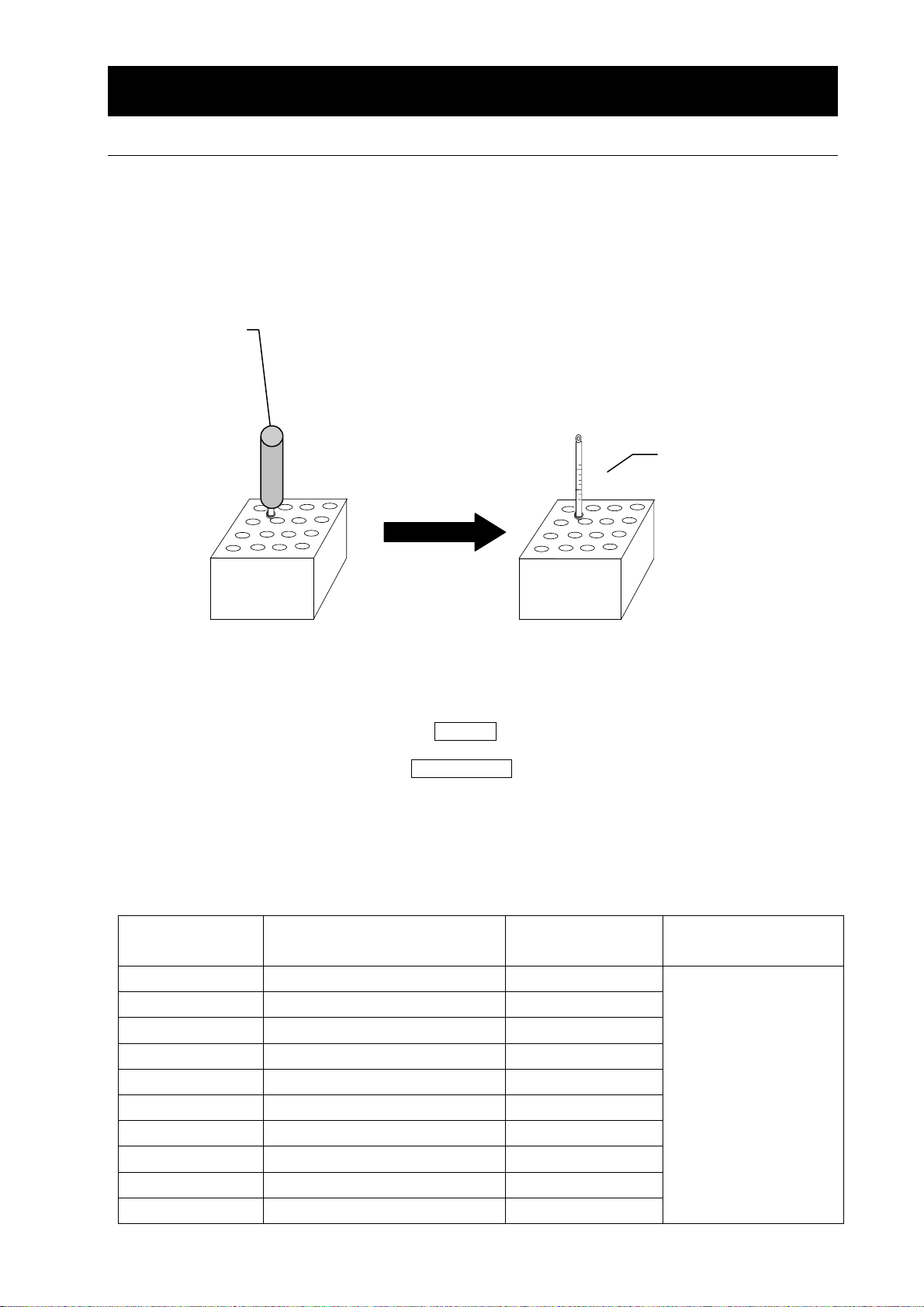
1. Mounting the aluminum
block
Hand grip for
aluminum block
Use the dedicated aluminum block available separately.
The use of an attached dedicated hand grip will prove convenient for
mounting/removal of the aluminum block.
Caution: ・ Possible hazard of burn. Use the hand grip when the
aluminum block is sufficiently cooled.
・ Do not raise the temperature while keeping the hand
grip left attached.
※ If necessary, a bar thermometer may be inserted into a
thermometer hole (used also for attaching the hand grip) of the
aluminum block.
(Use the thermometer of maximum 200℃ or more. Since the bar
thermometer is not attached, obtain it separately.)
Preparation
Bar thermometer
2. Connecting the power
cord
3. Installing the sample To maintain the temperature accuracy, use a sample container
4. Turning ON power
supply
5. Starting operation Press the START/STOP key of the operation panel for one second,
Connect the power cord to an appropriate receptacle firmly.
The receptacle to be connected must be of a 100V 15A type.
appropriate in size to the sample installation hole of the aluminum
block.
Turn ON the POWER switch of the mai n body and set the desired
temperature using▲▼ keys of the operation panel.
and the operation begins.
Aluminum block, which is available separately
The following types of aluminum blocks are available for HF100/HF200. Be sure to use the
aluminum block dedicated to the product concerned.
Specify the product code No. when purchasing.
Product code № Name/size No. of blocks that
can be set
213173 For 0.5m micro tube 48
213174 For 1.5m micro tube 36
213181 For 12 ㎜ test tube 36
213182 For 15 ㎜ test tube 25
213183 For 16.5 ㎜ test tube 25
213184 For 18 ㎜ test tube 20
213175 For 21 ㎜ test tube 12
213176 For 24 ㎜ test tube 12
213185 For 25 ㎜ test tube 12
213177 For 30 ㎜ test tube 8
Can be used
commonly for
HF21/41/61
4
Page 9
2. How to operate the unit
List of operation modes and functions
The operation functions of the product are as follows.
Nomenclature Description
№
Fixed-value operation Continuous operation mode
1
Press the START/STOP key for one second after temperature
setting, and the continuous operation begins. Pressing the
START/STOP key again for one second causes stop of
operation.
Quick auto-stop
2
operation
Auto-stop operation Used “to set the automatic stop at the specified time” before
3
Auto-start operation Used to start the automatic operation in several hours, that is,
4
※ The temperature and timer’s set time can be changed during operation.
※ Cautions for the auto-stop operation
・ The timer does not start counting till the bath temperature reaches the set level.
・ When the set temperature is below the bath temperature, the timer does not start
counting till the bath temperature drops below the set temperature.
The operation functions of sub-menu of the product are as follows.
Keep pressing the TIMER key for four seconds. The mode changes to the sub-menu mode.
Calibration offset
1
function
Power failure
2
compensation selection
function
The operation function of this device is as follows.
Nomenclature Description
№
Over-temperature
1
preventive function
Causes activation of the timer halfway of fixed-value
operation, then automatic operation stop after the set period.
This function is used “to set the automatic stop after the set
time”, “to set, in the course of operation, the automatic stop in
several hours.”
starting the operation. In the auto-stop mode, the timer starts
counting when the set temperature is reached.
“to set the automatic start at the specified time.”
The calibration offset function is to compensate for any
difference occurring between the target bath temperature and
controller control temperature (sensor temperature).
Compensation can be made either to the positive or negative
side over the entire temperature range of the system.
This is a function to select automatic or manual return to the
operation state after power failure.
Automatic return with
OFF
The automatic over-temperature preventive function is
incorporated.
When the bath temperature rises excessively along with the
set temperature of the device, this is set to activate
automatically at +12℃.
Stop operation when this function is activated. The Alarm
lamp flashes. To cancel, turn ON the power switch newly
again (manual reset).
ON and manual return with
Page
P.6
P.8
P.11
P.15
P.21
Page
P.19
5
Page 10

2 How to operate the unit
Fixed-value operation(continuous operation)mode
For fixed-value operation
In this mode, the operation is started (by pressing the(START/STOP key for one second)and
continued at the set temperature till power supply is turned OFF (by pressing the START/STOP key
for one second).
SV
SV:Temperature set value t:Time
▲
Operation start
1. Turn ON the POWER switch to start power supply.
Fixed Temp.
Auto Stop
Auto Start
Heater
Alarm
Measured Temp.
Set Temp.
℃
t
▲
Power OFF
POWER
The initial screen is shown for four seconds.
OFF
TIMER
SUB MENU 4sec.
START
STOP
Fixed Temp.
Auto Stop
Auto Start
Heater
Alarm
TIMER
SUB MENU 4sec.
Measured Temp.
Set Temp.
2.Set the temperature.
Fixed Temp.
Auto Stop
Auto Start
Heater
Alarm
TIMER
SUB MENU 4sec.
Measured Temp.
Set Temp.
START
STOP
START
STOP
℃
℃
The temperature setting screen appears after the initial
screen has been shown for four seconds.
Shows the current bath temperature.
Shows the current set temperature.
Set the desired temperature with ▼ and ▲ keys.
The set temperature rises with the ▲ key and lowers
with the ▼ key.
Set the temperature over a range from the
room temperature + 5.0℃ up to 200.0℃.
6
Page 11

3. Start operation.
Fixed Temp.
Auto Stop
Auto Start
Heater
Alarm
TIMER
SUB MENU 4sec.
Measured Temp.
Set Temp.
4. Stop operation.
Fixed Temp.
Auto Stop
Auto Start
Heater
Alarm
TIMER
SUB MENU 4sec.
Measured Temp.
Set Temp.
2. How to operate the unit
Fixed-value operation(continuous operation)mode
℃
START
STOP
℃
START
STOP
Keep pressing the START/STOP key.
Fixed Temp. and Heater lamps go ON and the operation
begins.
When the bath temperature reaches the set
temperature, the Heater lamp flashes. Now the bath
temperature is under control.
With Fixed and Heater lamps ON, the bath temperature
begins rising and the operation begins.
Keep pressing the START/STOP key.
Fixed Temp. and Heater lamps go OFF and the
operation stops.
Fixed and Heater lamps go OFF and the operation
stops.
The temperature can be set over a range from 0.0℃ to 200.0℃.
Note however that the operating temperature range is from the room temperature + 5.0℃
up to 200.0℃.
With this switch ON, the power is supplied to
Displays of the
operation panel
used for fixed-value
operation
POWER switch
▼ and ▲ keys
Measured Temp. screen
Set Temp. screen
Fixed Temp. lamp
Heater lamp
START/STOP key
:
the system. With the switch OFF, power
supply is turned OFF. This switch is a
circuit breaker.
:
Key to change the set temperature.
:
Shows the current bath temperature.
:
Shows the set temperature.
:
Indicates that the fixed-value operation state
:
is under way.
ON with the heater energized and flashing
:
for the controlled state
Operation start/stop key. Keep pressing for a
certain period.
7
Page 12

2. How to operate the unit
Quick auto-stop operation
For quick auto-stop operation
In this mode, the fixed-value operation being under way is stopped automatically with the timer
setting.
SV
t
Start of fixed-value operation Operation stop (automatic)
SV:Temperature set value t:Time
The quick auto-stop operation is performed in the fixed-value operation mode.
1. Start operation.
Fixed Temp.
Auto St op
Auto Start
Heater
Alarm
TIMER
SUB MENU 4sec.
Measured Temp.
Set Temp.
2.Set the desired time.
Fixed Temp.
Auto St op
Auto Start
Heater
Alarm
Measured Temp.
Set Temp.
STA R T
STOP
Timer setting
▼
Start with timer
℃
℃
Press lightly the TIMER key during fixed-value
operation. The Set Temp. screen changes to display
the time and flashes, with the Auto Stop lamp entering
the flash state.
The time set immediately before the operation is
shown.
Set the desired time with ▼ and ▲ keys.
TIMER
SUB MENU 4sec.
STA R T
STOP
The timer can be set over a range from 0.01(1 minute) to 999.5(999 hours 50 minutes).
The timer indicates the time in minutes from 0.01 to 99.59 and in ten minutes from 100.0
to 999.5.
8
Page 13

3.Start the auto-stop time.
Fixed Temp.
Auto St op
Auto Start
Heater
Alarm
TIMER
SUB MENU 4sec.
Measured Temp.
Set Temp.
℃
STA R T
STOP
4. Time-up
Fixed Temp.
Auto St op
Auto Start
Heater
Alarm
TIMER
SUB MENU 4sec.
Measured Temp.
Set Temp.
℃
STA R T
STOP
5. End of the quick auto-stop operation
Fixed Temp.
Auto St op
Auto Start
Heater
Alarm
Measured Temp.
Set Temp.
℃
2. How to operate the unit
Quick auto-stop operation
Press the START/STOP key.
The Auto Stop lamp changes from flashing to the
continuous ON state, and auto-stop operation begins.
The timer starts counting when the bath temperature
reaches the set level.
The display changes from the set time to the remaining
time.
At the set time, the display changes from the remaining
time to the flashing display of End
the end of auto-stop operation.
The display changes to End
.
To cancel the quick auto-stop oper ation, keep pressing
the START/STOP key. The operation ends and the
screen returns to the temperature setting screen.
Indicates the current bath temperature.
Indicates the current set temperature.
. This means
TIMER
SUB MENU 4sec.
STA R T
STOP
Counting of the timer during the quick auto-stop operation
When the temperature set in the quick auto-stop operation is lower than the bath
temperature, the timer does not start counting till the bath temperature reaches the set
level.
9
Page 14

Displays of the
operation panel
used for quick
auto-stop operation
POWER switch
▼ and ▲ keys
Measured Temp. screen
Set Temp. screen
Fixed Temp. lamp
Auto Stop lamp
Heater lamp
START/STOP key
TIMER key
2. How to operate the unit
Quick auto-stop operation
With this switch ON, the power is supplied to
:
the system. With the switch OFF, power
supply is turned OFF. This switch is a circuit
breaker.
:
Key to change the set temperature or the time
of timer
:
Indicates the current bath temperature.
:
Indicates the set temperature. Indicates the
set and remaining times of the timer.
:
Indicates that the operation is in the
:
fixed-value mode.
ON during auto-stop operation and flashing
:
for the time period set with the timer
ON with heater energized and flashing in the
:
controlled state
Operation start/stop key. Keep pressing for a
certain period.
This is also a timer start key for addition of
auto-stop timer operation in the fixed-value
:
operation mode.
Key to set the time during setting of the
auto-stop timer. Press the TIMER key lightly
to show the timer set time.
10
Page 15

2. How to operate the unit
Auto-stop operation
For the auto-stop operation
In this mode, the operation stops automatically according to the setting of the timer.
Timer set
▼
SV
t
SV:Temperature set value t:Time
Quick auto-stop function is to set auto-stop in the course of fixed-value operation. This
section describes the method of operation, in which the auto-stop timer is set at the initial set
time point.
1.Turn ON the POWER switch to start power supply.
Z
Fixed Temp.
Auto Stop
Auto Start
Heater
Alarm
Measured Temp.
Set Temp.
Timer start
▼
Timer operation start (auto)
Operation stop (auto)
The initial screen is shown for four seconds.
℃
POWER
OFF
Fixed Temp.
Auto Stop
Auto Start
Heater
Alarm
TIMER
SUB MENU 4sec.
TIMER
SUB MENU 4sec.
Measured Temp.
Set Temp.
START
STOP
The temperature setting screen appears after the initial
screen has been shown for four seconds.
Indicates the current bath temperature.
℃
Indicates the current set temperature.
START
STOP
11
Page 16

2.Set the temperature.
Fixed Temp.
Auto Stop
Auto Start
Heater
Alarm
TIMER
SUB MENU 4sec.
Measured Temp.
Set Temp.
℃
START
STOP
3. Select the auto-stop mode.
Fixed Temp.
Auto St op
Auto Start
Heater
Alarm
Measured Temp.
Set Temp.
℃
2. How to operate the unit
Auto-stop operation
Set the desired temperature with ▼ and ▲ keys.
The set temperature rises with the ▲ key and lowers
with the ▼ key.
The temperature can be changed even in the course of
operation.
Press the TIMER key lightly to allow the
AStP indicating the auto-stop operation
mode to appear. The Set Temp. screen shows the time.
Indicates AStP
operation mode.
Indicates the time set immediately before operation.
that means the auto-stop
TIMER
SUB MENU 4sec.
STA R T
STOP
4. Set the time of the timer.
Fixed Temp.
Auto Stop
Auto Start
Heater
Alarm
TIMER
SUB MENU 4sec.
Measured Temp.
Set Temp.
℃
START
STOP
The timer can set over a range from 0.01(1 minute) to 999.5(999 hours 50 minutes).
The timer indicates the time in minutes from 0.01 to 99.59 and in ten minutes from 100.0
to 999.5.
Set the time with ▼ and ▲ keys.
The time display screen changes to flashing and the
screen changes to the time setting screen.
12
Page 17

5. Start the auto-stop operation.
Fixed Temp.
Auto St op
Auto Start
Heater
Alarm
Measured Temp.
Set Temp.
℃
2. How to operate the unit
Auto-stop operation
Keep pressing the START/STOP key.
Auto-stop operation begins.
The timer starts counting when the set temperature is
reached.
TIMER
SUB MENU 4sec.
STA R T
STOP
・Starting counting of the timer in the auto-stop operation mode
When the set temperature is lower than the bath temperature in the auto-stop
operation mode, the timer does not start counting till the bath temperature reaches
the set temperature.
・The set temperature and the time of timer can be changed even during operation.
Change the set temperature directly with ▼ and ▲ keys. The display changes from
the remaining time to the temperature setting screen, enabling temperature change.
The screen changes automatically to the remaining time display. There is not need
to press the START/STOP key after change.
To change the time of timer, press lightly the TIMER key. The set time display
flashes. Change the time to the desired time with ▼ and ▲ keys. The screen
changes automatically to the remaining time display. There is not need to press the
START/STOP key after change.
6. Time-up
Fixed Temp.
Auto St op
Auto Start
Heater
Alarm
TIMER
SUB MENU 4sec.
Measured Temp.
Set Temp.
℃
STA R T
STOP
At the set time, the remaining time display changes to
the flashing display of End
. This means the
end of the auto-stop operation.
Changes over to End
.
13
Page 18

7. End of the auto-stop operation
Fixed Temp.
Auto St op
Auto Start
Heater
Alarm
Measured Temp.
Set Temp.
℃
2. How to operate the unit
Auto-stop operation
To cancel the auto-stop operation, keep pressing the
START/STOP key. The operation ends and the screen
returns to the temperature setting screen.
Indicates the current bath temperature.
Indicates the current set temperature.
TIMER
SUB MENU 4sec.
Displays of the
operation panel
used for auto-stop
operation
POWER switch
▼ and ▲ keys
Measured Temp. screen
Set Temp. screen
Auto Stop lamp
Heater lamp
START/STOP key
TIMER key
STA R T
STOP
With this switch ON, the power is supplied to
:
the system. With the switch OFF, power
supply is turned OFF. This switch is a
circuit breaker.
:
Key to change the set temperature or the
time of timer.
:
Indicates the current bath temperature.
:
Indicates the set temperature. Indicates the
set and remaining times of the timer.
:
ON during auto-stop operation
:
ON with heater energized and flashing in the
controlled state
:
Operation start/stop key. Keep pressing for
a certain period.
:
This is a key to set the time of timer during
setting of the auto-stop timer. Press the
TIMER key lightly during fixed-value
operation to show the timer set time.
14
Page 19

2. How to operate the unit
Auto-start operation
For the auto-start operation
This mode is selected when the operation is to be started automatically in several hours later as
shown below. Since the operation does not stop automatically, it is necessary to stop it manually.
SV
Timer set
t
Timer start Operation start (auto)
Controller start (manual)
SV:Temperature set value t:Time
1.Turn ON the POWER switch to start power supply.
Z
Fixed Temp.
Auto Stop
Auto Start
Heater
Alarm
Measured Temp.
Set Temp.
℃
POWER
OFF
The initial screen is shown for four seconds.
Fixed Temp.
Auto Stop
Auto Start
Heater
Alarm
TIMER
SUB MENU 4sec.
TIMER
SUB MENU 4sec.
Measured Temp.
Set Temp.
START
STOP
The temperature setting screen appears after the initial
screen has been shown for four seconds.
Indicates the current bath temperature.
℃
Indicates the current set temperature.
START
STOP
15
Page 20

2. Set the temperature.
Fixed Temp.
Auto Stop
Auto Start
Heater
Alarm
TIMER
SUB MENU 4sec.
Measured Temp.
Set Temp.
℃
START
STOP
3. Select the auto-start mode.
Fixed Temp.
Auto St op
Auto Start
Heater
Alarm
Measured Temp.
Set Temp.
℃
2. How to operate the unit
Auto-start operation
Set the desired temperature with ▼ and ▲ keys.
The set temperature rises with the ▲ key and lowers
with the ▼ key.
The temperature can be changed even in the course of
operation.
Press the TIMER key lightly to allow AStr
indicating the auto-stop operation mode to appear. The
time is shown in the Set Temp. screen.
Indicates AStr
mode.
Indicates the time set immediately before operation.
meaning the auto-stop operation
TIMER
SUB MENU 4sec.
STA R T
STOP
4. Set the time of timer.
Fixed Temp.
Auto Stop
Auto Start
Heater
Alarm
TIMER
SUB MENU 4sec.
Measured Temp.
Set Temp.
℃
START
STOP
The timer can set over a range from 0.01(1 minute) to 999.5(999 hours 50 minutes).
The timer indicates the time in minutes from 0.01 to 99.59 and in ten minutes from 100.0
to 999.5.
Set the time with ▼ and ▲ keys.
The time display screen changes to flashing and the
screen changes to the time setting screen.
16
Page 21

5.Start the auto-start operation.
Fixed Temp.
Auto Stop
Auto Start
Heater
Alarm
Measured Temp.
Set Temp.
℃
2. How to operate the unit
Auto-start operation
Keep pressing the START/STOP key.
Auto-start operation begins.
TIMER
SUB MENU 4sec.
START
STOP
6. Time-up
Fixed Temp.
Auto St op
Auto Start
Heater
Alarm
TIMER
SUB MENU 4sec.
Measured Temp.
Set Temp.
℃
STA R T
STOP
7. End of the auto-start operation.
Fixed Temp.
Auto St op
Auto Start
Heater
Alarm
Measured Temp.
Set Temp.
℃
At the set time, the set temperature is shown in the Set
Temp. screen.
To cancel the auto-start operation, keep pressing the
START/STOP key. The operation ends and the screen
returns to the temperature setting screen.
Indicates the current bath temperature.
Indicates the current set temperature.
TIMER
SUB MENU 4sec.
STA R T
STOP
17
Page 22

Displays of the
operation panel
used for auto-start
operation
POWER switch
▼ and ▲ keys
Measured Temp. screen
Set Temp. screen
Auto Start lamp
Heater lamp
START/STOP key
TIMER key
2. How to operate the unit
Auto-start operation
With this switch ON, the power is supplied to
:
the system. With the switch OFF, power
supply is turned OFF. This switch is a
circuit breaker.
:
Key to change the set temperature or the
time of timer.
:
Indicates the current bath temperature.
:
Indicates the set temperature. Indicates the
set and remaining times of the timer.
:
ON during auto-start operation
:
ON with heater energized and flashing in the
controlled state
:
Operation start/stop key. Keep pressing for
a certain period.
:
This is a key to set the time of timer during
setting of the auto-stop timer. Press the
TIMER key lightly during fixed-value
operation to show the timer set time so as to
show the time set with timer.
18
Page 23

2. How to operate the unit
Other functions
Over-temperature preventive function
This product incorporates two types of over-temperature preventive functions.
1.Automatic over-temperature
preventive device
Before shipment, this device has been set in such a manner that
it interlocks with the set temperature of the device and is
activated automatically at the set temperature + 12℃ in case of
abnormal rising of bath temperature.
When activated, the over-temperature preventive function
causes stop of operation and flashing of the Alarm lamp. To
cancel the function, turn ON the Power switch newly again after
allowing the bath temperature to lower (manual reset).
When the symptom is not improved, the circuitry (temperature
controller, etc.) may be faulty. Contact a shop from which you
have purchased the product, our safes office, or our customer
service center.
2. Independent over-temperature
preventive device
If abnormal overheat continues because of failure of the
automatic over-temperature preventive function, resulting in the
bath temperature rise up to 230 ℃ , the built-in bimetal
over-temperature preventive device is activated, shutting off
power supply to the heater.
Activation of this device may be due to failure of the circuitry
(temperature controller, etc.). Contact a shop from which you
have purchased the product, our safes office, or our customer
service center.
Set value lock function
This function is to lock the set contents to prevent arbitrary change.
1. Select the Lock function from the sub-menu function.
Fixed Temp.
Auto St op
Auto Start
Heater
Alarm
TIMER
SUB MENU 4sec.
Measured Temp.
Set Temp.
℃
STA R T
STOP
Keep pressing the TIMER key for four seconds and
select the sub-menu mode. Allow LocK
indicating the set-value lock function to appear. The Set
Temp. screen shows off
been made and on when any setting has been
made.
Shows LocK
indicating the set-value lock mode.
Shows either off
or on .
when no setting has
4 sec.
19
Page 24

2.LocK the set value.
Fixed Temp.
Auto St op
Auto Start
Heater
Alarm
Measured Temp.
Set Temp.
℃
2. How to operate the unit
Other functions
Select “on” with the ▲ key, and the set value is locked.
Shows on .
TIMER
SUB MENU 4sec.
STA R T
STOP
3. Cancel the LocK function.
Fixed Temp.
Auto St op
Auto Start
Heater
Alarm
TIMER
SUB MENU 4sec.
Measured Temp.
Set Temp.
4 sec.
℃
STA R T
STOP
Keep pressing the TIMER key for four seconds to select
the sub-menu mode and to allow LocK
indicating the set-value lock function to appear. The Set
Temp. screen shows off
.
Shows Lock
indicating the set-value lock mode.
Shows off
.
20
Page 25

2. How to operate the unit
Other functions
Calibration offset function
The calibration offset function is to ensure agreement between the bath temperature and set
temperature by compensating the temperature difference, if any, between the bath temperature
actually measured with the reference thermometer or temperatur e recorder and the temperature set
with the controller (as read on the controller).
Enter the plus-side temperature difference to the calibration offset setting when the bath
temperature exceeds the set value and the minus-side temperature difference to the above setting
when the bath temperature is lower than the set level.
1.Measure the bath temperature
Wait till the bath temperature stabilizes, then check the difference between the bath temperature and
the measurement indicator of this device. The bath temperature can be measured corr ectly by using
the calibrated temperature recorder in the small amount of silicone oil filled into the aluminum block.
Temperature after compensation
on the minus side
Current temperature
Temperature after
compensation on the plus
side
Temperature recorder sensor
Small amount (about 2 ml) of silicone oil
(for the aluminum block for 16.5㎜ test tube)
Aluminum block
21
Page 26

2. How to operate the unit
Other functions
2.Select the calibration offset function from the sub-menu function.
Fixed Temp.
Auto St op
Auto Start
Heater
Alarm
TIMER
SUB MENU 4sec.
Measured Temp.
Set Temp.
4秒
℃
STA R T
STOP
3. Enter the offset temperature.
Enter the temperature difference on the minus side when the bath temperature is lower than the
temperature controller reading value.
Enter the temperature difference on the plus side when the bath temperature is higher than the
temperature controller reading value.
Repeat this step till the bath temperature and the temperature controller reading value agree.
Setting can be completely within a short period by first entering the compensation temperature
lower than the difference of both of them, then by allowing it to approach the target level gradually.
Fixed Temp.
Auto St op
Auto Start
Heater
Alarm
Measured Temp.
Set Temp.
℃
Keep pressing the TIMER key for four seconds to select
the sub-menu mode. First, the set-value lock function is
displayed. Press the TIMER key again, and
cAL
indicating the calibration offset function
appears.
The Set Temp. screen shows the compensation
temperature.
Shows cAL
indicating the calibration offset mode.
Shows the offset temperature set immediately before
operation.
Enter the temperature difference in the Set Temp.
screen.
Upon completion of the setting, keep pressing the
TIMER key. The screen returns to the temperature
setting screen.
Enter the temperature difference.
TIMER
SUB MENU 4sec.
STA R T
STOP
22
Page 27

3. In Case of Trouble
The controller displays the following errors.
In case of error, the heater output stops, the Alarm lamp flashes to notify abnormality.
Record the error code, turn OFF power supply, and carry out the service call.
Error code Details
Temperature input circuit
error
Er01
Er15
Not
displayed
Not
displayed
For details of over-temperature preventive device, refer to P.19.
Alarm lamp
flashing only
-
Temperature sensor error
Error of outside the
measured temperature
display range
Memory error
Over-temperature
prevention error
Over-temperature
prevention error
Broken or disconnected sire of
temperature sensor, error in the
temperature input circuit
Check the sensor and temperature
controller and replace if necessary.
Cancelled by resetting power supply.
Memory set value error in the
temperature controller
Board replacement necessary。
Abnormal temperature rise, resulting in
activation of the auto over-temperature
preventive device
Canceled by resetting power supply.
Abnormal temperature rise, resulting in
activation of the independent
over-temperature preventive device
Carry out the service call.
Error display
T roubleshooting guide
Troubleshooting
Symptom Countermeasure
No startup even with
POWER and START/STOP keys
ON
◆ If neither of above two cases applies, turn OFF the POWER switch immediately.
Disconnect the power plug and contact a shop from which you have purchased the
product, our safes office, or our customer service center.
・Check if the master power supply is ON.
・Check if power failure has occurred.
23
Page 28

4. Specifications
Main body
Type HF100 HF200
No. of installed
aluminum blocks
Operating
temperature range
Temperature control
accuracy
Temperature rise
time
Temperature
controller
Temperature setting
method
Minimum
temperature setting
Temperature setting
method
Heater 370W 600W
Sensor Pt100Ω
Safety devices
Functions
Overall dimensions About 230W×310D×139H About 340W×310D×139H
Internal bath
dimensions
Weight About 5 ㎏ About 6.5 ㎏
About 30 minutes(room temperature at
Automatic over-temperature preventive function (main relay OFF at the set
temperature + 12℃, manual reset)
Independent over-temperature preventive device (manual reset type bimetal,
activated temperature at about 230℃)
Fixed-value operation, quick auto-stop operation, auto-stop operation, auto-start
operation, self-diagnosis function, automatic over-temperature preventive
function, set-value lock function, calibration offset function, power failure
compensation function
(16.5φ block used)
7-segment LED, set temperature, and bath temperature displayed
About 1 12W×112D×70H About 222W×112D×70H
1 piece 2 pieces
Room temperature + 5.0℃~200.0℃
±0.2℃
(16.5φ block used)
About 35 minutes (room
23℃)
PID control with microcomputer
▲ and ▼ keys
0.1℃
Functioning both as POWER switch and circuit breaker
temperature at 23℃)
±0.2℃
Power supply AC100V 3.8A±10% AC100V 6.1A±10%
Accessories Heating block mounting/removal fixture, operation manual, warranty card
※ The temperature control accuracy has been determined according to our testing method.
This is the value measured using an aluminum block for 16.5 mm test tube at the room temperature of
23℃.
Optional accessories
Aluminum block dimensions 110 W×110D×70H(common to all blocks)
№
1 213173 OBH80 For 0.5m micro tube 48
Types of aluminum block
2 213174 OBH82 For 1.5m micro tube 36
3 213181 OBH84 For 12 ㎜ test tube (common to HF21/41/61) 36
4 213182 OBH86 For 15 ㎜ test tube(common to HF21/41/61) 25
5 213183 OBH88 For 16.5 ㎜ test tube(common to HF21/41/61) 25
6 213184 OBH90 For 18 ㎜ test tube(common to HF21/41/61) 20
7 213175 OBH92 For 21 ㎜ test tube 12
8 213176 OBH94 For 24 ㎜ test tube 12
9 213185 OBH96 For 25 ㎜ test tube(common to HF21/41/61) 12
Product
code
Type Aluminum block specification
No. of
racks
10 213177 OBH98 For 30 ㎜ test tube 8
24
Page 29

5. Wiring Diagram
Symbol Name of part Symbol Name of part
H Mica heater X1 Main relay
TIC Control board SSR Non-contact relay
PIO Display board
CP
POWER switch(circuit
breaker)
Pt100Ω
OH
Temperature sensor
Bimetal type
Over-temperature preventive device
25
 Loading...