

Page 1

● Thank you for choosing DP Series Vacuum Drying
Ovens by Yamato Scientific Co., Ltd.
● For proper equipment operation, please read this
instruction manual thoroughly before use. Always
keep equipment documentation safe and close at
hand for convenient future reference.
Warning: Read instruction manual warnings and
cautions carefully and completely
before proceeding.
VACUUM DRYING OVENS
Model DP200/300/410/610
Instruction Manual
First Edition
Yamato Scientific Co., Ltd.
Printed on recycled paper
Page 2

TABLE OF CONTENTS
1. SAFETY PRECAUTIONS ........................................................................................................... 1
Explanation of Symbols ......................................................................................................................... 1
Symbol Glossary ................................................................................................................................... 2
Warnings and Cautions ......................................................................................................................... 3
2. PRE-OPERATION PROCEDURES ............................................................................................ 4
Installation Precautions & Procedures .................................................................................................. 4
Vacuum System Information ................................................................................................................. 9
3. COMPONENT NAMES AND FUNCTIONS ............................................................................... 11
Unit Overview 1 ................................................................................................................................... 11
Control Panel ....................................................................................................................................... 13
4. OPERATION PROCEDURE ..................................................................................................... 14
Prior Confirmation ............................................................................................................................... 14
Decompression/Purge Procedure ....................................................................................................... 14
Setting Date & Time ............................................................................................................................ 15
Keypad Tone Function ........................................................................................................................ 16
Mode and Function Flow ..................................................................................................................... 17
Constant Temperature Mode .............................................................................................................. 18
Auto Stop Mode ................................................................................................................................... 20
Auto Start Mode................................................................................................................................... 22
Programmed Operation ....................................................................................................................... 24
Building Programs ............................................................................................................................... 27
Keypad Lock Function ......................................................................................................................... 31
Calibration Offset Function .................................................................................................................. 32
Recovery Modes ................................................................................................................................. 33
CO2 Emissions & Power Consumption Settings ................................................................................ 34
Data Backup & Reset .......................................................................................................................... 35
Data Monitoring ................................................................................................................................... 36
Independent Overheat Prevention Device .......................................................................................... 37
5. HANDLING PRECAUTIONS .................................................................................................... 38
6. MAINTENANCE PROCEDURE ................................................................................................ 43
Inspection and Maintenance ............................................................................................................... 43
7. EXTENDED STORAGE & DISPOSAL ..................................................................................... 44
Extended Storage / Unit Disposal ............................................................................................................. 44
Disposal Considerations...................................................................................................................... 44
8. TROUBLESHOOTING .............................................................................................................. 45
Error Code Guide ................................................................................................................................ 45
Troubleshooting Guide ........................................................................................................................ 46
9. SERVICE & REPAIR ................................................................................................................ 48
10. SPECIFICATIONS .................................................................................................................. 49
11. ACCESSORIES ...................................................................................................................... 51
Optional Accessory Guide ................................................................................................................... 51
12. WIRING DIAGRAM................................................................................................................. 53
13. WEAR ITEMS ......................................................................................................................... 57
14. LIST OF HAZARDOUS SUBSTANCES ................................................................................. 58
15. SETUP CHECKLIST ............................................................................................................... 59
Page 3
A Word Regarding Symbols
Various symbols are provided throughout this text and on equipment to
ensure safe operation. Failure to comprehend the operational hazards and
risks associated with these symbols may lead to adverse results as explained
below. Become thoroughly familiar with all symbols and their meanings by
carefully reading the following text regarding symbols before proceeding.
Warning
Caution
Signifies a situation which may result in minor injury (Note 2)
and/or property damage (Note 3)
(Note 1) Serious injury is defined as bodily wounds, electrocution, bone
breaks/fractures or poisoning, which may cause debilitation requiring
extended hospitalization and/or outpatient treatment.
(Note 2) Minor injury is defined as bodily wounds or electrocution, which will not
require extended hospitalization or outpatient treatment.
(Note 3) Property damage is defined as damage to facilities, equipment, buildings or
other property. ( Note 1 ) Serious injury is defined as bodily wounds,
Symbol Meanings
Signifies warning or caution.
Specific explanation will follow symbol.
Signifies restriction.
Specific restrictions will follow symbol.
Signifies an action or actions which operator must undertake.
Specific instructions will follow symbol.
Signifies a situation which may result in serious
injury or death (Note 1)
1. SAFETY PRECAUTIONS
Explanation of Symbols
1
Page 4
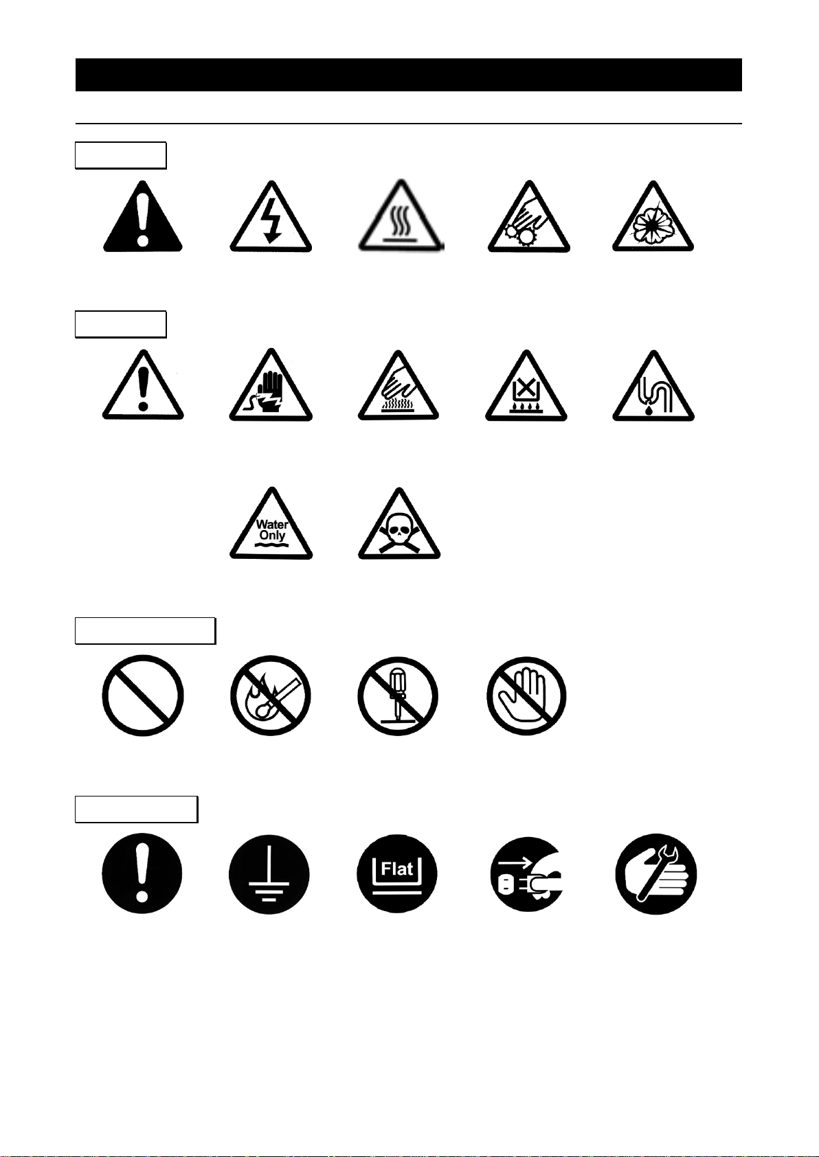
General Warning
Danger!:
High Voltage
Danger!:
Extremely Hot
Danger!:
Moving Parts
Danger!:
Blast Hazard
General Caution
Caution:
Electrical Shock
Hazard!
Caution: Burn
Hazard!
Caution: Do Not
Heat Without
Water!
Caution: May
Leak Water!
Caution: Water
Only
Caution: Toxic
Chemicals
General
Restriction
No Open Flame
Do Not
Disassemble
Do Not Touch
General Action
Required
Connect Ground
Wire
Level Installation
Required
Disconnect Power
Inspect
Regularly
Warning
Caution
1. SAFETY PRECAUTIONS
Symbol Glossary
Restriction
Action
2
Page 5
Warning
Never operate equipment near combustible gases/fumes.
Do not install or operate DP series unit near flammable or explosive gases/fumes. Unit is NOT fire
or blast resistant. Negligent use could cause a fire/explosion.
See “List of Hazardous Substances” (P.58).
Always ground equipment.
Always ground this unit properly to avoid electric shock.
DO NOT operate equipment when abnormalities are detected.
If smoke or unusual odors begin emitting from unit, or if any other abnormalities are detected,
terminate operation immediately, turn off main power switch (Earth Leakage Breaker - “ELB”) and
disconnect power cable. Continued operation under such conditions may result in fire or electric
shock.
DO NOT operate with bundled or tangled power cable.
Operating unit with the power cable bundled or otherwise tangled, may cause power cable to
overheat and/or catch fire.
DO NOT damage power cable.
Damaging the power cable by forcibly bending, pulling or twisting may cause fire or electric shock to
the operator.
NEVER disassemble or modify equipment.
Attempting to dismantle or modify unit in any way, may cause malfunction, fire or electric shock.
DO NOT touch hot surfaces.
Some surfaces on this unit become extremely hot during operation. Exercise vigilance in order to
avoid getting burned.
DO NOT insert multiple power cables into a single outlet.
Inserting multiple cords into a single outlet, using branch outlets or extension cords, may cause
power cable to overheat and/or catch fire. Other issues may include a drop in voltage, which may
affect performance, resulting in failure to control or maintain proper temperatures.
Caution
DO NOT operate equipment during thunderstorms.
In the event of a thunderstorm, terminate operation and turn off main power switch (ELB)
immediately. A direct lightning strike may cause damage to equipment, or result in fire or electric
shock.
1. SAFETY PRECAUTIONS
Warnings and Cautions
3
Page 6
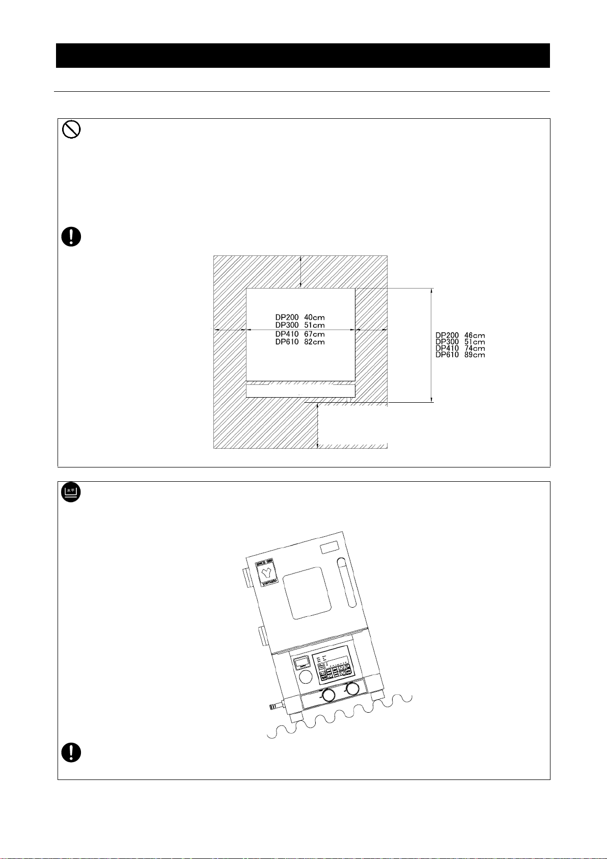
Do not install DP series unit:
・where flammable or corrosive gases/fumes will be generated.
・where exterior temperature will exceed 35ºC, will fall below 5ºC or will fluctuate.
・in excessively humid or dusty locations.
・where there is constant vibration.
・where power supply is erratic.
・in direct sunlight or outdoors.
Install DP series oven(s) in a location with sufficient space and ventilation as specified as below.
Install unit on a level and even surface. Failure to do so may result in abnormal vibrations or
noise, possibly causing complications and/or malfunction.
Approximate unit weight:
DP200: approx. 45kg, DP300: approx. 72kg, DP410: approx. 210kg, DP610: approx. 310kg.
Handle with care. Transportation and installation should always be done by two or more people.
Min. 20cm
Min. 20cm
Equipment
Door
DP200: Min. 40cm
DP300: Min. 50cm
DP410: Min. 65cm
DP610: Min. 80cm
Min. 20cm
2. PRE-OPERATION PROCEDURES
1. Choose an appropriate installation site.
Installation Precautions & Procedures
2. Install on a level surface.
4
Page 7
In the event of an earthquake or other unforeseen incident, equipment may unexpectedly shift or
fall, causing injury. Taking preventative steps to install unit in a safe location, away from room
access doors and out of other danger is strongly recommended.
Install unit so that side panel heat vents (see “Unit Overview 1” on P.11 for location) are
unobstructed and allowed to sufficiently diffuse heat. Failure to do so may result in excessive
temperatures inside the unit control panel, causing possible degraded CPU board performance,
malfunction or fire. See installation specifications above.
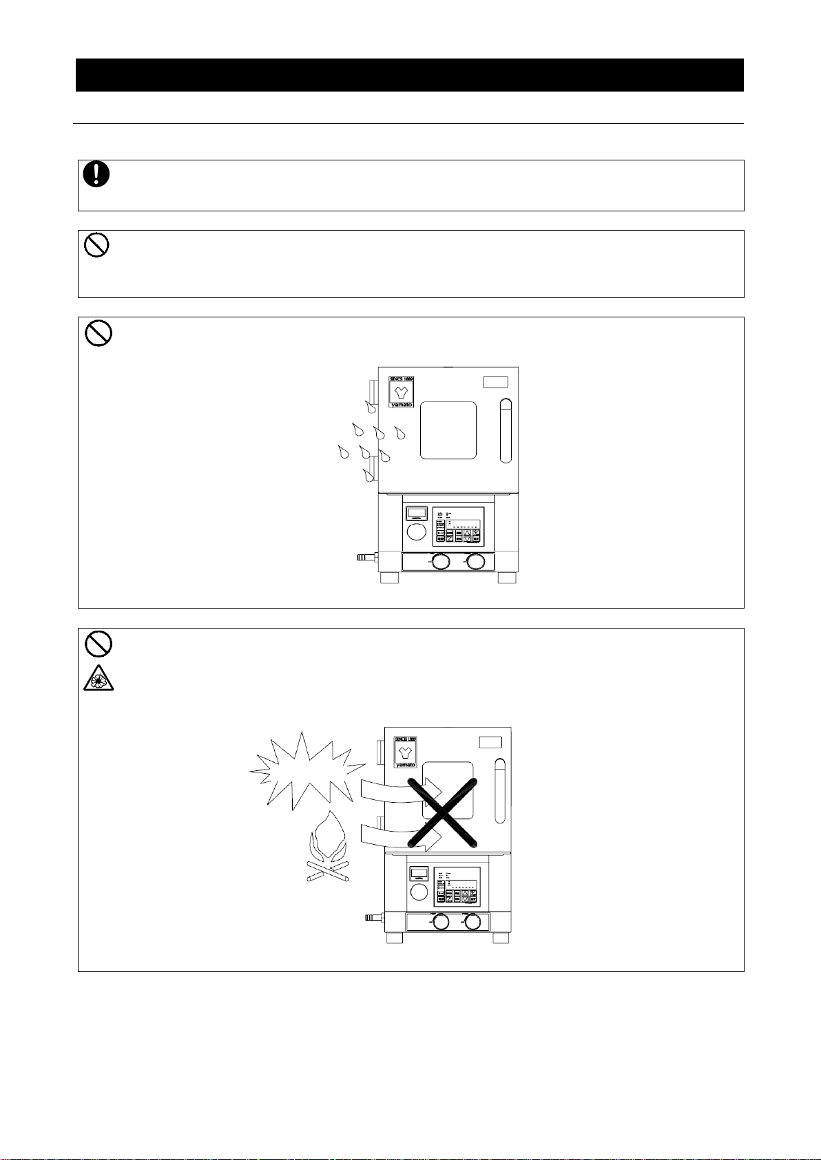
Install unit where it will be free from liquid spray and other moisture. Failure to do so may result
in control mechanisms becoming wet, causing malfunction, electrical shock and/or fire.
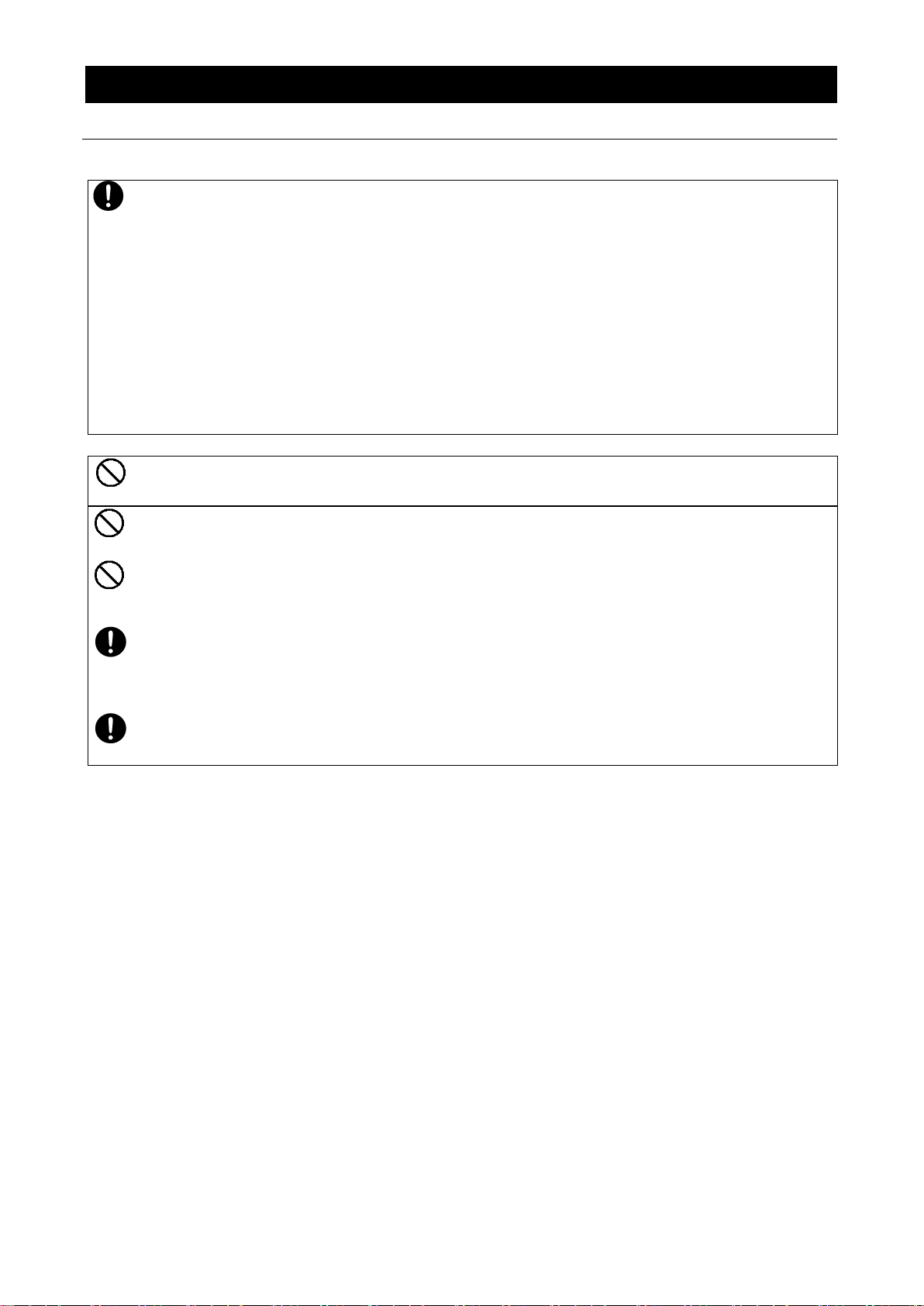
Never install near flammables or explosives. This unit is NOT fire or blast resistant. Simply
switching the main power switch (ELB) “ON” or “OFF” can produce a spark, which could relay
during operation, causing a fire or explosion when near flammable or explosive fluids, chemicals
or gases/fumes. See “List of Hazardous Substances” (P.58).
Explosives
Flammables
2. PRE-OPERATION PROCEDURES
Installation Precautions & Procedures
3. Install in a safe location.
4. Install in a well-ventilated area (DP200/300 only).
5. Install in a dry location.
6. Install in a location free of flammables and explosives.
5
Page 8
Connect power cable to a suitable facility outlet or terminal, according to the following electrical
requirements.
Electrical requirements:
DP200 Single phase 100V AC 50/60Hz 7A
DP300 Single phase 100V AC 50/60Hz 11A
DP410 Single phase 200V AC 50/60Hz 11.5A
DP610 Single phase 200V AC 50/60Hz 16A
※Check the line voltage on outlet or terminal to be used and properly evaluate whether to utilize
a line being shared by other equipment. If the unit is not activated by turning on the main
power switch (ELB), take an appropriate course of action, such as connecting the unit to a
dedicated power source.
※Multiple power cables connected to a single outlet may cause unit input voltage to drop,
resulting in degraded heating and temperature control performance.
Never operate unit with power cable bundled or tangled; and do not modifiy, bend, forcibly twist
or pull on power cable. Doing so may cause fire and/or electrical shock.
Do not risk damage to power cable by positioning it under desks or chairs, or by pinching it
between objects. Doing so may cause fire and/or electrical shock.
Do not place power cable near kerosene/electric heaters or other heat-generating devices.
Doing so may cause power cable insulation to overheat, melt and/or catch fire, which may result
in electric shock.
Turn off main power switch (ELB) immediately and disconnect from facility terminal or outlet, if
power cable becomes partially severed or damaged in any way. Failure to do so may result in
fire or electric shock.
Contact a local dealer or Yamato sales office for information about replacing power cable if it is
damaged.
Always connect power cable to appropriate facility outlet or terminal.
7. Connect to power supply.
8. Handle power cable with care.
2. PRE-OPERATION PROCEDURES
Installation Precautions & Procedures
6
Page 9

・ Ground wire must be connected to a proper grounding line or teminal in order to avoid
electrical shock.
・ Never connect ground wire to gas lines or water pipes.
・ Never connect ground wire to telephone grounding lines or lightening rods. Doing so may
result in fire or electric shock.
・ Never insert multiple plugs into a single outlet. Doing so may result in power cable
overheating, fire or drop in voltage.
Connect to grounded outlet.
Outlet with ground receptacle
When no grounding terminal is found:
●Grounding to Electrical Equipment Technical
Standards, Section 19, class D (Grounding
Resistance Max. 100Ω) is required in Japan.
Contact a local dealer, electrician, or Yamato
Sales office for location-specific electrical
requirements.
Use grounded adapter for ungrounded outlets.
Outlet with no ground receptacle
Ground adapter
●Insert grounded power plug into ground
adapter. Connect grounding wire (green) from
ground adapter to a ground terminal.
・ Grounding to Electrical Equipment Technical Standards, Section 19, class D (Grounding
Resistance Max. 100Ω) is required in Japan where no grounding terminal is provided. Contact a
local dealer, electrician, or Yamato Sales office for location-specific electrical requirements.
・ Connect terminals securely to facility terminal or to an appropriate connector.
Plugs and connectors are not included with
this unit. Ground unit properly to facility
outlet or terminal as required.
Never connect ground wire to gas lines, water pipes, telephone grounding lines or lightening
rods. Doing so may result in fire or electrical shock.
Confim that the facility main breaker is OFF before
connecting the round terminals from the power cable. No
power plugs or connectors of any kind are included with
DP410/610. Where required, purchase an appropriate
plug and properly connect using the round terminals.
Wire color
Terminal
Black
Live side
White
Neutral side
Green
Ground
Ungrounded outlet
100V AC only
Ground adapter
Grounded plug
Grounding wire
with Y-terminal
W
w
G
Grounded plug
3 (three) Round Terminals for M5 screws
Green (to grounding terminal)
Black (to facility terminal)
White (to facility terminal)
Grounding prong
2. PRE-OPERATION PROCEDURES
Installation Precautions & Procedures
9.(1) Ground wire MUST be connected properly (DP200/300 at 100V AC).
9.(2) Ground wire MUST be connected properly (DP410/610 220V AC).
10. Observe wire color designation when connecting to facility terminal (DP410/610
200V AC) See table below.
7
Page 10
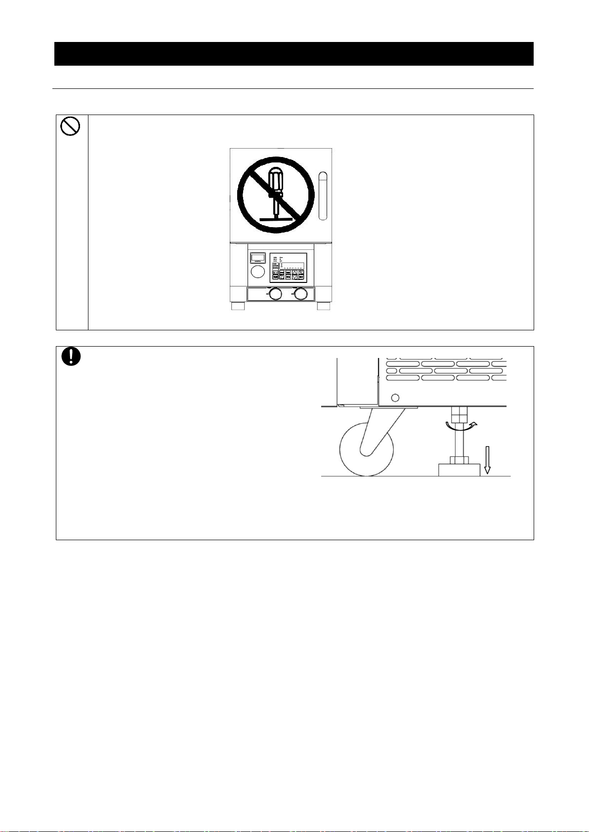
11. DO NOT disassemble or modify.
Attempting to disassemble or modifiy this unit in any way may result in malfunction, fire or
electric shock.
Position the 2 (two) adjustable leveling feet,
located on the undercarriage of DP410/610
units.
After unit is installed, position the adjustable
leveling feet using the following procedure:
① Rotate leveling feet down until unit stands
securely on the floor.
② Check for any gaps between the floor and
4 (four) contact points (e.g. the 2 ‘two’
front leveling feet and the 2 ‘two’ rear
casters).
③ Once unit is secure, tighten both leveling
feet stop nuts firmly against the topmost
nut, to prevent leveling feet from turning
under vibration.
①
③
2. PRE-OPERATION PROCEDURES
Installation Precautions & Procedures
12. Position adjustable leveling feet (DP410/DP610 only).
8
Page 11

Item
Model
(Pump
Connection
Port Size)
Manufacturer
or Supplier
Vacuum
Pump
Model
(sold
separately)
Effective
Pump
Displacement
(at 50/60Hz)
in litters/min.
Pump
Inlet
Size
Required vacuum line components
DP200/300
(Pump
connection port
:18mm)
Yamato
Science
PD53*1
50/60
18 mm
・15 mm ID vacuum hose
Qty 1
PX52*1
PD103
100/120
27 mm
・15 mm ID vacuum hose
・25 mm ID vacuum hose
・Reducing pipe(18/27)
A(Brass)/C(Stainless St.)
Qty 1
Qty 1
Qty 1
PD138*1
135/162
PX137*1
135/162
30 mm
DP410/610
(Pump
connection
port
:NW25
flange)
Yamato
Science
PD138
*1
135/162
27 mm
・25 mm ID vacuum hose
・Vacuum hose adapter
・Clamp (NE20/25)
・Center ring (NW25)
Qty 1
Qty 1
Qty 1
Qty 1
PD203*1
200/240
PX137
135/162
30 mm
PX202
200/240
Adixen
M(T)2010
142/170
NW25
flange
・Flexible hose
・Clamp (NW20/25)
・Center ring (NW25)
Qty 1
Qty 2
Qty 2
M(T)2015
208/250
M(T)2010C
142/170
M(T)2015C
208/250
Kashiyama
NeoDry15E
250
NW25
flange
・Flexible hose
・Clamp (NW20/25)
・Center ring (NW25)
Qty 1
Qty 2
Qty2
2. PRE-OPERATION PROCEDURES
Vacuum System Information
Vacuum System Information
Vacuum pumps and vacuum line components (sold separately) for DP series ovens
(1) Vacuum pump models and vacuum line components (sold separately), required for DP series
ovens, are shown in Table 2.1. Select an appropriate vacuum pump and vacuum line components
(sold separately) using the table below. Note that an appropriate check valve must also be selected
for vacuum pumps (sold separately). Vacuum line components are also offered as options and
available upon request.
Table 2.1 Vacuum pump models and required line components (sold separately) for DP series ovens
【Note】
・ *1 These pump models can be fitted with components for the KF-style quick-coupling flange, as on
all Adixen pump models.
・ If an existing vacuum pump is to be connected to a new DP series unit, and their inlet sizes do not
match, use an appropriate reducing joint.
(2) Be sure to use the proper vacuum line components between vacuum pump (sold separately) and
DP series unit to prevent any vacuum leaks.
(3) If an existing pump cabinet is to be used for a new vacuum pump (sold separately) installation on
DP models 410/610, be sure to place the vacuum pump (sold separately) inside of the cabinet so
that the oil gauge faces front and can be easily viewed and regularly inspected.
9
Page 12
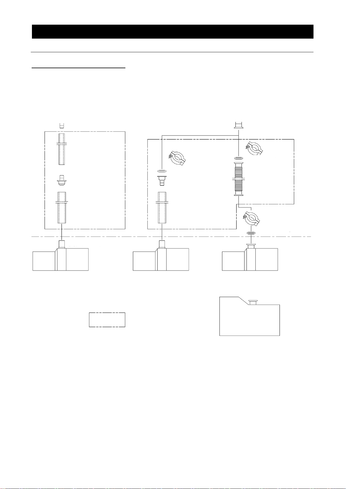
φ18mm OD
DP200/DP300 pump connection port
Reducing joint
A(Brass) or C(Stailess St.)
Vacuum hose(φ15mm ID )
Vacuum hose (φ25mm ID)
DP410/610 pump connection port
NW25 flange
Clamp
Clamp
Center ring
Center ring
Vacuum hose adapter
Flexible hose
Vacuum hose (φ25mm ID)
Connection port sizeφ30mm, φ27mm
Connection port sizeφ30mm, φ27mm
Connection port size NW25 flange
Clamp
Center ring
Rotary Vacuum Pump
PD138/203, PX137/202 etc.
Rotary Vacuum Pump
KF25 quick-coupling specifications for M(T)2010/2015/2021,
PD/PX etc.
(Note)
components inside
broken line are
optional
Air-cooled Dry Vacuum Pump
NeoDry 15E
2. PRE-OPERATION PROCEDURES
Vacuum System Information
Vacuum System Information
Vacumm pump and vacuum line components (sold separately) for DP series ovens
10
Page 13

Control Panel
Independent
Overheati
Door Handle
Viewing Window
Vacuum Gauge
Pump Valve Knob
(closes with CW rotation)
Purge Valve Knob
(closes with CW rotation)
Caution-Rating
Spec. sticker
Heat Vents
Terminal Block Cover
(Terminal Block: option)
Main Power Switch (ELB)
Legs
Serial No. sticker
Door
Heat Vents
Pump Port
Purge Port
Power Cable w/plug
3. COMPONENT NAMES AND FUNCTIONS
DP200/300 overview
Unit Overview 1
11
Page 14
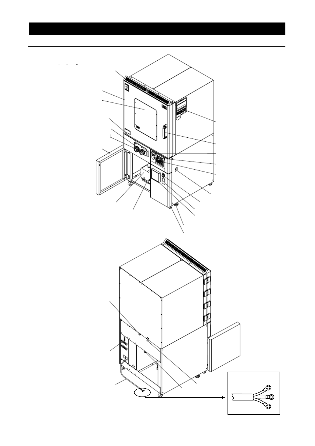
Round Terminals
Purge Port
Pump Port
N2 Gas Inlet
(optional)
4(four) Casters
Safety Cover (DP610 only)
Door
Viewing Window
Flow Meter
(option)
Pump Valve Knob
(closes with CW rotation)
Purge Valve
(closes with CW rotation)
Vacuum Pump Cabinet Door
Vacuum Pump
(sold separately)
Pump slide tray (optional)
Caution-Rating sticker
Serial No. sticker
Door Handle
Independent
Overheat
Prevention Device
Vacuum Gauge
Control Panel
Main Power Switch
(ELB)
External Vacuum Pump Switch (optional)
Adjustable Leveling Feet (2 ‘two’ on undercarriage)
Digital Pirani Vacuum Gauge (optional)
Memory Recorder (option)
Terminal Block
(optional)
Power Cable
(Round terminals)
DP410/610 overview
3. COMPONENT NAMES AND FUNCTIONS
Unit Overview 2
12
Page 15
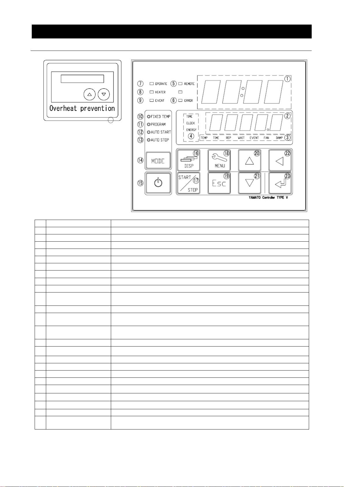
No
Name
Description
1
Upper Display
Readout for temperature reading (current chamber temp), error codes, etc.
2
Lower Display
Readout for temperature setting, clock, timer, etc.
3
Function Indicator Lamps
Illuminates (one or more) to show which function is currently running or active
4
Mode Indicator Lamps
Illuminates (only one) to show which mode is currently running.
5
REMOTE Indicator Lamp
Illuminates while remote comm (optional item) transmission is in progress.
6
ERROR Indicator Lamp
Illuminates when an error occurs.
7
OPERATE Indicator Lamp
Illuminates during operation. Flashes in operation standby mode.
8
HEATER Indicator Lamp
Illuminates when heaters are receiving power.
9
EVENT Indicator Lamp
Illuminates when event output (optional item) is transmitted.
10
FIXED TEMP Indicator
Lamp
Illuminates during constant temperature operation.
11
PROGRAM Indicator Lamp
Illuminates during programmed operation. Flashes while entering program settings.
12
AUTO START Indicator
Lamp
Illuminate during auto start operation.
13
AUTO STOP Indicator
Lamp
Illuminates during auto stop operation.
14
MODE key
Press to switch between operation modes, ⑩~⑬ on control panel.
15
POWER key
Press and hold to switch between unit idle and unit standby.
16
DISP key
Press to switch between monitoring options in lower display.
17
START/STOP key
Press to start or stop an operation.
18
MENU key
Press to switch between setting options.
19
Esc key
Press to return to previous menu without finalizing settings.
20
▲(Up) key
Press to increase setting value.
21
▼(Down) key
Press to decrease setting value.
22
key
Press to move cursor left.
23
ENTER key
Press to finalize setting items.
24
Independent Overheat
Prevention Device
Set device to keep unit from exceeding a certain temperature.
24
3. COMPONENT NAMES AND FUNCTIONS
Control Panel
13
Page 16

4. OPERATION PROCEDURE
Prior Confirmation
(1) Power source and ground wire
Be sure to connect power cable to an appropriate power source and confirm that ground wire is
connected.
(2) Main power switch (ELB)
Turn ELB ON.
Test ELB function once a month or before extended operation. See “Maintenance Procedures”
(P.43) for details.
Check the lower display on the control panel when ELB is turned on and confirm it is showing
current time.
(3) Independent Overheat Prevention Device (IOPD)
Be sure to set IOPD temperature 20ºC over the chamber temperature setting.
Test IOPD function before each instance of extended operation. See “Maintenance Procedures”
(P.43) for details.
(4) Vacuum line connection
Be sure to connect unit securely to vacuum pump (sold separately).
(5) Vacuum pump (sold separately)
Check vacuum pump oil level and be sure it is free of contamination.
Decompression/Purge Procedure
(1) Decompressing unit chamber
1. Close purge valve.
2. Close the pump valve.
3. Turn vacuum pump ON.
4. Open the pump valve.
Note: open pump valve gradually when processing powdery or frothy test samples.
(2) Repressurizing unit chamber
1. Close pump valve.
2. Open purge valve to allow ambient pressure back into chamber.
3. Open Pump Valve.
4. Shut vacuum pump OFF.
Note: open purge valve gradually when processing powdery test samples.
14
Page 17
The backup battery installed in DP series units, is a wear item and has an estimated life of
approximately 5 years. Replacing battery within the 5-year lifespan is recommended.
※ Contact a local dealer or Yamato sales office to request a replacement battery. If unit has
program data in memory, make a data backup file before replacing backup battery. See “Data
Backup” (P.35) in this section for details.
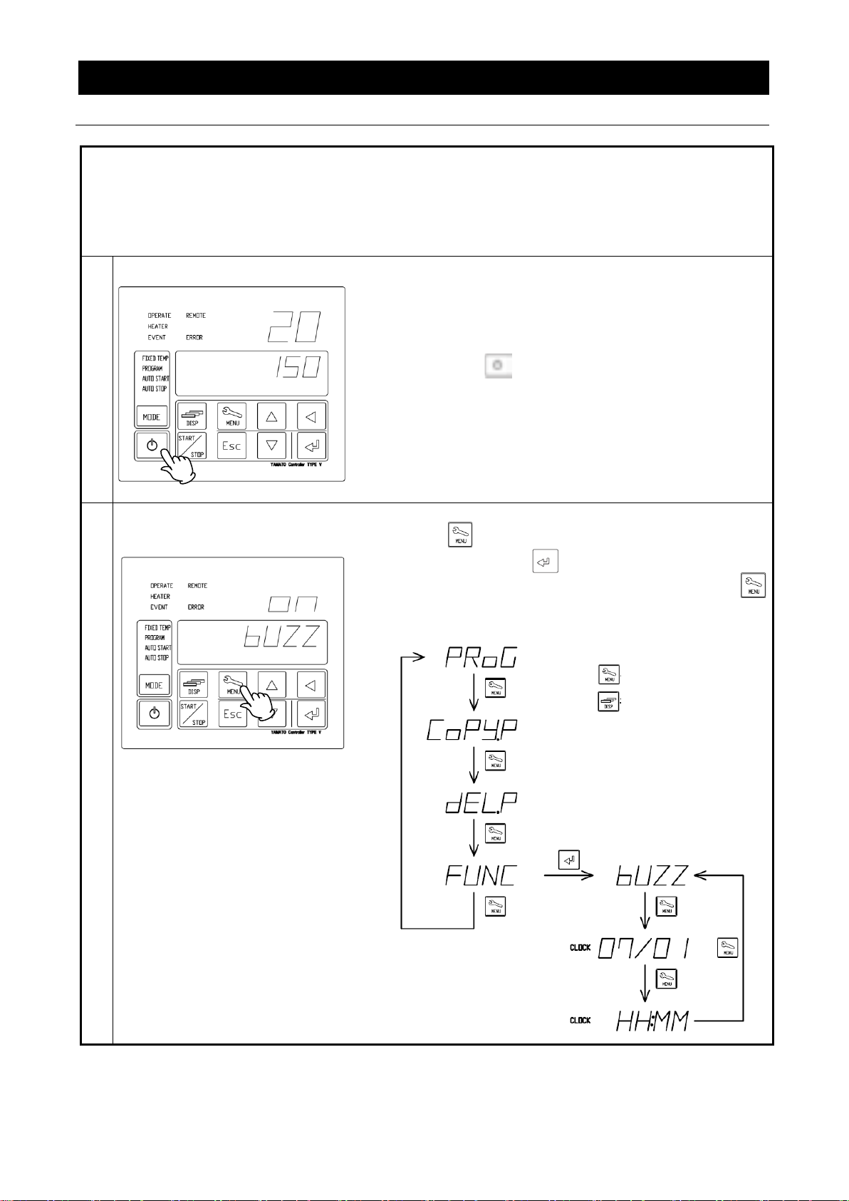
To set the current date & time,after replacing backup battery, follow the steps below.
1
Turn on power.
Turn ON the main power switch (ELB), located on the right
panel of the DP series units.
Lower display on the control panel will show the time.
This indicates that the machine is in “idle”.
Press and hold to display the standby screen.
Upper display shows current temperature in the chamber
while lower display shows current temperature setting.
This indicates that the machine is in “standby”.
2
Use the MENU key to view date
and time in displays
①
Press repeatedly until FUNC appears in lower
display, then press .
②
When [bUZZ] is shown in the lower display, press
to view the year in upper display, and month/date in
lower display.
is used to advance to
next item
is used to return to
previous item
4. OPERATION PROCEDURE
Setting Date & Time
15
Page 18
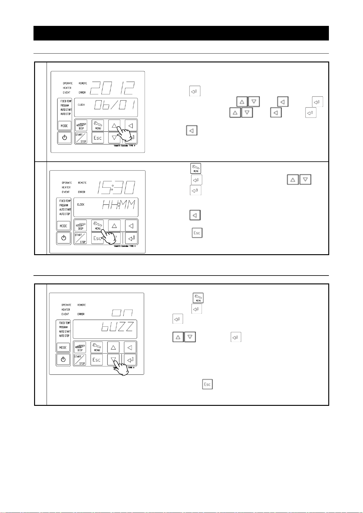
3
Set the date.
Setting the year/month/date and clock.
①
Year and month/date are shown on upper and lower
displays respectively.
②
Press . Settable value begins flashing.
③
Set calendar year with and . Press .
④
Set month/date with and . Press .
※
Press to change digit (flashing) positions.
4
Set the time.
①
Press .
②
Press and set current time with and
press .
Set time in conformance to the 24-hour time system
(e.g. military time, continental time or railway time).
※Press to change digit (flashing) positions.
③
Press twice to return to initial screen when
time/date settings are completed.
1
Set keypad tone.
①
Press repeatedly until FUNC is shown, then
press to bring up bUZZ in lower display. Press
. oFF begins flashing in upper display.
②
Select one of three keypad tone modes using
and press .
on: Activates tone for all keys. (factory default).
CLK: Activates tone for POWER and ENTER keys
only.
oFF: Deactivates tone for all keys.
Press the key twice to go back to initial screen
when keypad tone settings are completed.
4. OPERATION PROCEDURE
Setting Date & Time
Keypad Tone Function
16
Page 19
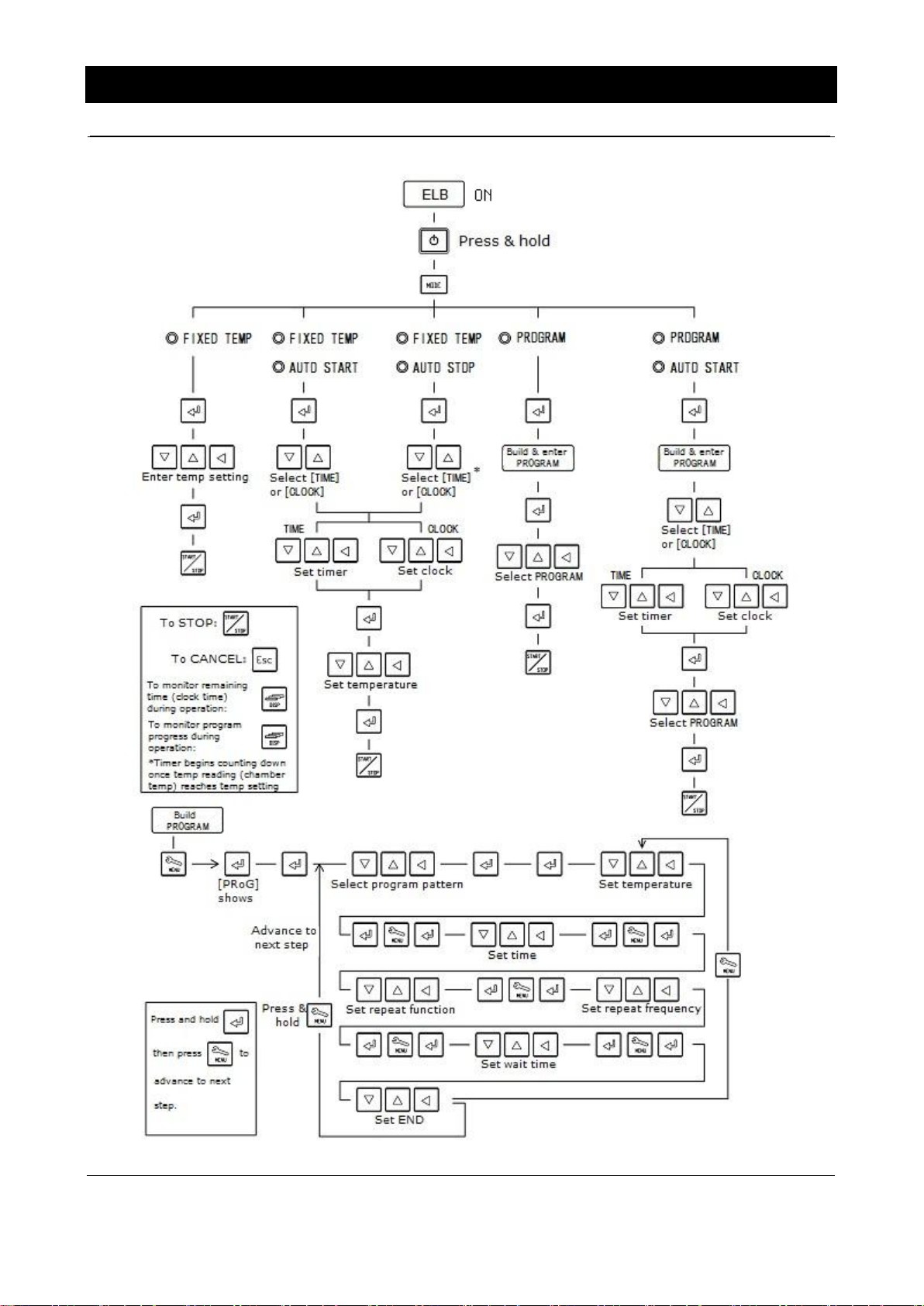
Mode and Function Flow
4. OPERATION PROCEDURE
17
Page 20

FIXED TEMP (constant temperature) mode runs DP series unit at a constant selected
temperature until START/STOP key is pressed, manually terminating operation.
SV: Set Value (temperature setting), t:Time
Setting constant temperature mode.
1
Turn on power.
Turn ON main power switch (ELB), located on right
panel of unit. (idle)
Press and hold to turn on power.
(standby)
Chamber temperature is shown in upper display,
Temperature setting is shown in lower display.
2
Select constant temperature mode.
Press repeatedly until FIXED TEMP indicator
lamp comes on.
※ Factory default temperatures are shown in upper
and lower displays on first-time start-up. All
subsequent start-ups will default to last temperature
values entered.
3
Set objective temperature.
①
Press . Changeable digits flash in lower
display.
②
Toggle between digits using and enter
desired value using .
Operating Temperature Range:
DP200/300:40~240ºC (Setting range: 0~250ºC)
DP410/610: 40~20ºC (Setting range: 0~210ºC)
③
Press once temperature setting has been
entered.
Press once or twice to cancel setting.
SV
t
▲
Set temperature → START
▲
Press POWER key or
Press STOP key to terminate program.
4. OPERATION PROCEDURE
Constant Temperature Mode
18
Page 21

4
Start/stop constant temperature
operation
Press to start or stop (terminate)
constant temperature operation.
5
Set quick auto stop mode
The quick auto stop function is used to
automatically stop constant temperature operation
at a certain time (clock) or after a certain time
(timer) has passed.
(decided during operation)
①
Press while unit is running in constant
temperature mode.
②
QStoP is shown in lower display and the [TIME]
lamp will begin flashing.
③
Select the stop mode (TIME or CLOCK) using
, and press .
④
Set TIME(setting range: 0~99hr:0~59min)or
CLOCK (24-hour time system only) in upper
display and press .
⑤
When timer reaches 0:00 or when clock and the
time setting agree, operation stops and “ENd”
appears in lower display.
⑥
Press to clear “End” from display.
※
Press to monitor temperature and remaining
time during operation, when desired.
Example 1. Quick auto stop mode w/timer:
In the example below, operation stops automatically
in 2 hours and 30 minutes AFTER target
temperature is reached.
Example 2. Quick auto stop mode w/clock:
In the example below, operation is stopped
automatically at 3:00 p.m. REGARDLESS of
when target temperature is reached.
4. OPERATION PROCEDURE
Constant Temperature Mode
19
Page 22

AUTO STOP (Automatic Stop) utilizes timer or clock to automatically stop an operation.
Operation must be started manually. See below.
SV: Set Value (Temperature setting), t:Time
Programming auto stop mode
1
Turn on power
Turn on main power switch (ELB), located on the right
panel of unit. (idle)
Press and hold to turn on power. (standby)
Chamber temperature is shown in upper display.
Temperature setting is shown in lower display.
2
Select auto stop mode
Press repeatedly until both the FIXED TEMP
and AUTO STOP indicator lamps are illuminated.
※
Constant temperature mode is the factory default
setting and will be the mode selected on first-time
startup. On subsequent startups will default to last
mode run.
3
Set temperature and operation time.
①
Press .
Select TIME or CLOCK using , and press
.
②
Set TIME (setting range: 0~99hr:0~59min)or
CLOCK (24-hour time system only) in upper
display and press .
③
Set temperature in lower display and press .
※See explanation
regarding “wait mode”
on page 29.
t
SV
Operation start
(manual)
Operation stop
(automatic)
Timer: Start counting
Timer: Wait
4. OPERATION PROCEDURE
Auto Stop Mode
20
Page 23

4
Start / stop operation
①
Press to start or stop (terminate) operation
at any time.
②
When timer reaches 0:00, or when clock and
slected end-time agree, “ENd” will show in lower
display.
③
Press to clear “ENd” from display.
※
Press to monitor temperature and remaining
time during operation, when desired.
Example 1. Auto stop mode w/timer:
In the example below, operation is stopped
automatically in 2 hours and 30 minutes AFTER
temperature setting of 50ºC is reached.
Example 2. Auto stop mode w/clock:
In the example below, operation will automatically
terminate at 3:00 p.m. REGARDLESS of when target
temperature is reached.
4. OPERATION PROCEDURE
Auto Stop Mode
21
Page 24

AUTO START (Automatic Start) mode utilizes timer or clock to automatically begin an operation.
Operation must be stopped manually.
Start timer counting Start operation (automatically)
Setting Automatic Start Mode
1
Turn on power
Turn on main power switch (ELB), found on the right
panel of unit. (idle)
Press and hold to turn on power.
(standby)
Chamber temperature is shown in upper display.
Temperature setting is shown in lower display.
2
Select auto start mode
Press repeadedly until both FIXED TEMP and
AUTO START lamps illuminate.
※
Constant temperature mode is the factory default
setting and will be the mode selected on first-time
startup. On subsequent startups will default to last mode
run.
3
Set temperature and start time.
①
Press .
Select TIME or CLOCK using , and press
.
②
Set TIME (setting range: 0~99hr:0~59min) or
CLOCK (24-hour time system only) in upper display
and press .
③
Set temperature in lower display and press .
t
4. OPERATION PROCEDURE
Auto Start Mode
22
Page 25

4
Start /stop operation
④
Press to enter standby (wait) mode.
⑤
The OPERATE indicator lamp begins flashing and
start timer or clock shows in the lower display.
※ Chamber temperature is shown in upper display.
Timer or clock is seen in lower display, depending
on which mode is selected for auto start.
⑥
Press to terminate operation at any time.
※
Press to monitor temperature and remaining
time during operation, when desired.
Example 1.
Auto start mode w/timer:
in the example below, operation automatically
begins 2 hours and 30 minutes, after is
pressed.
Example 2.
Auto start mode w/clock:
When is pressed In the example below,
operation begins automatically at 3:00 p.m.
4. OPERATION PROCEDURE
Auto Start Mode
23
Page 26

PROGRAM mode runs a combination of times and temperatures in a series of programmed
steps as one operation. See below.
PV: Process Value (ambient temperature)
Entering Pattern Programs
1
Turn on power
Turn on main power switch (ELB) found on the right
panel of unit. (idle)
Press and hold to turn on power.
(standby)
Chamber temperature is shown in upper display.
Temperature setting is shown in lower display.
*Enter a target program prior to running first cycle.
2
Enter a program.
Program steps entered and program patterns saved
may not exceed 99 in total.
Example:
A total of 11 program patterns can be stored with a
maximum of 9 programmed steps each.
※Note regarding “program repeat function”.
It is not possible to cut into and repeat process
steps, in part (crossing) or in full (reduplication),
from anywhere upstream in the process program,
during operation.
See "Programming Procedure" (P.27) for details on
program entry.
(Temp.)
Step 1
Step 2
Step 3
Step 4
Step 5
Step 6
Step 7
Step8
Start programmed cycle
End programmed cycle
(Time)
Start PV
Target temp.
4. OPERATION PROCEDURE
Programmed Operation
24
Page 27

3
Select program mode
Press repeatedly until PROGRAM lamp
illuminates.
“PGM:XX” will show in lower display. (Last program entered
or used will always be the one shown in the display on
start-up)
※
Constant temperature mode is the factory default
setting and will be the mode selected on first-time
startup. On subsequent startups will default to last mode
run.
4
Select program pattern number
Press . “01” begins flashing in lower display. Select
the desired program pattern number using and
press .
5
Start program mode
Press to start programmed operation.
※
If the “end” setting is left out on the final step of a
program pattern, the entire program will not run. If newly
entered programs fail to run, confirm that all settings
have been entered correctly.
4. OPERATION PROCEDURE
Programmed Operation
25
Page 28

Example 1: Program pattern #2 has 6 steps and contains a repeat cycle which, repeats steps 4
to 6, five times and ends. (STEP1,2,3→STEP 4, 5 and 6× five times→END)
Program Criteria:
STEP1: Set 100°C, 0 minute, wait ON
STEP2: Set 100°C, 2 hours, wait OFF
STEP3: Set 150°C, 0 minute, wait ON
STEP4: Set 150°C, 2 hours, wait ON
STEP5: Set 200°C, 1 hour, wait OFF
STEP6: Set 200°C, 2 hours, repeat from step #4, repeat 5 times, wait ON, end ON
NO
Display
Entry procedures (for Example1 above)
1-1
Standby screen
1-2
Step1
1-3
Enter 02:01 (Pattern #02, step #01)
1-4
Enter 100 (100°C)
1-5
Enter 00:00 (00 hr 00 min)
STEP 1
STEP 2
STEP 3
STEP 4
STEP 5
STEP 6
END
5 回繰返し
Repeat five times
Temperature
Time
Entering a new program.
4. OPERATION PROCEDURE
Building Programs
26
Page 29

1-6
Enter 0 (no repeat)
1-7
Enter 0 (no repeat)
1-8
Select “on” (to activate Wait Function)
(A set countdown time to when temperature reading is within ± 1℃ of
temperature reading)
1-9
Select “oFF” (Select "oFF" to program next step. Select "on" to program
current step as “end step”)
1-10
Programming for Step #1
complete. Now:
Press and hold .
2-1
Enter 02:02 (Pattern #02, step #02)
Step2
Step3
Step4
Step5
Enter the parameters for
steps #2 to #5 in the same
manner as step #1. (repeat
entry procedures 1-3~1-9)
※Press at any time while entering a program to show
[RESt.P] in the lower display and see remaining available steps in
upper display.
~ ~ ~
~
~
4. OPERATION PROCEDURE
Building Programs
27
Page 30

Step6
6-1
Enter 02:06 (Pattern #02, step #06)
6-2
Enter 200 (200°C)
6-3
Enter 02:00 (02 hr 00 min)
6-4
Enter 4 (to repeat step #4 from the beginning)
6-5
Enter 5 (to repeat five times)
6-6
Select “on” (to activate wait function)
(A set countdown time to when temperature reading is within ±1°C of
temperature reading)
6-7
Select “on” (Select "oFF" to advance to the next step. Select "on" to program
as the “end step”)
※Last step in the program MUST include “END setting”.
4. OPERATION PROCEDURE
Building Programs
28
Page 31

【Wait function explained】
If "starting temperature" and "temperature setting" are equal, chamber temperature is
maintained until timer reaches 0 (zero),.
If chamber temperature drops more than 3°C below or goes more than 6°C beyond
temperature setting, however, timer countdown stops and unit enters "wait mode" until
coolant temperature returns to within -3°C or +6°C of temperature setting. Timer then begins
counting down once again, from where it left off, until it reaches 0 (zero) and operation
finishes.
Target Temp.
Starting
Temp.
Temp.
Time
Set time
If timer setting is 0 (zero), temperature in chamber is raised to “temperature setting” on full
power. If "wait" is set to "on" (program mode), “wait mode” will be activated until chamber
temperature is within -3°C or +6°C of temperature setting.
Objective temp.
Start
Temp.
Temp.
Time
Time to objective Temp.
The following flowchart illustrates the repeat function concept.
Note that the first cycle of the repeating section is not counted as a repeating cycle.
Step # 1
No repeat command
Step # 2
No repeat command
Step # 3
No repeat command
Step # 4
Repeat start
Step :2
Times:5
Step # 5
Process repeat section to run five times
No repeat command
Waiting
4. OPERATION PROCEDURE
Wait Function
29
Page 32

Copy/delete program
・Copying a program.
①
Press repeatedly until [CoPY.P] appears in
lower display and press .
②
[SrC] shows in upper display. Use to select
program to copy in lower display and press .
Program is copied.
③
[dESt] appears in upper display. Using ,
select a number which the copied program will be
stored as and press . Program is duplicated with
new designation.
・
Deleting a program.
①
Press repeatedly until [dEL.P] appears in lower
display, then press .
②
[dEL] appears in upper display. Select a program
number to delete using , then press and hold
.
③
[dEL] flashes in upper display as warning that the
program number shown is about to be deleted.
Press again. Program is deleted.
4. OPERATION PROCEDURE
Program Copy & Delete
30
Page 33

1
Turn power OFF
Press and hold to turn power OFF so that current
time is showing in lower display (idle).
2
Enter password
①
Press and hold .
[UPASS] appears in lower display. “00” shows in
upper display with right digit flashing.
②
Use and to enter password “11” in
upper display and press (password is locked
to “11”).
3
Set keypad lock mode
①
[KLoCK] is shown in lower display. Press .
②
Use to select keypad lock mode and
press .
③
Press and hold to return to initial idle screen.
:
All keys enabled. (factory default)
:
All keys disabled except
key
and
START key.
:
key only is disabled.
:
key only is disabled.
4. OPERATION PROCEDURE
Keypad Lock Function
31
Page 34

The calibration offset feature makes it possible to compensate for any difference between the
temperature reading on the control panel and actual chamber temperature (taken manually). This
enables parallel compensation in either direction (+ or -) over the entire temperature setting
range on all DP series units.
Example
Actual chamber temperature is lower than the conrol panel temperature reading by 2°C:
Temperature reading can be calibrated by entering a calibration offset value of -2.0 to
compensate against the actual temperature deficiency of 2°C.
If the initial temperature reading was 200°C, it will read 198°C after offset calibration, and be brought
into agreement with the actual temperature.
※The -2°C calibration in the example above is applied over the entire temperature setting
range (0~250°C for DP200/300, & 0~210°C for DP410/610). Note that offset values may
change slightly depending on test sample arrangement in the chamber and/or
temperature setting.
1
Turn power OFF.
Press and hold to turn power OFF so that
current time shows in lower display (idle).
2
Enter password.
①
Press and hold .
[UPASS] will show in lower display. [00] shows in
upper display.
②
Using and , enter password, “11” in
upper display and press .
3
Set calibration offset value.
①
Press repeatedly until [CAL:oS] can be seen
in lower display and [0.0] in upper display. Press
.
②
Enter offset value using and . Press
.
Example
Temperature reading is 200°C, while actual
temperature (manually taken) is 198°C
⇒
Offset input value: -2
③
Press and hold to return to idle screen.
4. OPERATION PROCEDURE
Calibration Offset Function
32
Page 35

1
Turn power OFF
Press and hold to turn power OFF so the current
time shows in lower display (standby).
2
Enter the password
①
Press and .
[UPASS] will show in lower display and [00] in
upper display.
②
Use and to enter password “11” in
upper display and press .
3
Set recovery option.
①
Press repeatedly until [RECoV] shows in
lower display and press .
②
Use to select recovery mode and press
.
Cnt: Operation will resume where it left off at
power failure. (factory default)
StoP: Operation will teminate and unit will go into
idle when power is restored.
③
Press and hold to return to idle screen.
4. OPERATION PROCEDURE
Recovery Modes
Setting the recovery option in case of a power failure.
33
Page 36

1
Turn power OFF.
Press and hold to turn power OFF so that current
time is showing in lower display (idle).
2
Enter password.
①
Press and hold .
[UPASS] appears in lower display. “00” shows in upper
display with right digit flashing
②
Use and to enter password “11” in
upper display and press (password is locked to
“11”).
3
Set/reset monitored items.
①
Press repeatedly to show [ENERG] in lower
display. Press .
②
Press to select an item in lower display:
“PoW:Rt” (“oFF” in upper display)
:
Press to change “oFF” (constant) to → rUn
(flashing) in lower display.
Press to reset accumulated power
consumption.
Press to return to [PoW:Rt] screen.
KG.K 0555 (denoting 0.555 - factory default value):
Press to make value changeable (flashing).
Use and to change conversion factor
value.
Press , then to return to [KG.K] screen.
“Co2:Rt” (“oFF” in upper display)
:
Press to change “oFF” (constant) to → “rUn”
(flashing) in upper display.
Press to reset accumulated CO2 emissions.
Press to return to [Co2:Rt] screen.
③
Press and hold to return to initial idle screen.
4. OPERATION PROCEDURE
CO2 Emissions & Power Consumption Settings
Setting CO2 conversion factor & resetting total CO2 emissions/power consumption.
34
Page 37

1
Turn power OFF.
Press and hold to turn power OFF so that current
time is showing in lower display (idle).
2
Enter password.
①
Press and hold .
[UPASS] appears in lower display. “00” shows in
upper display with right digit flashing.
②
Use and to enter password “11” in
upper display and press (password is locked to
“11”).
3
Save data/show saved data/reset.
①
Press repeatedly to toggle through the
following items respectively in lower display:
U Bks: Backs up all setting information.
U bKR: Displays back up data.
INI.U: Resets all settings to factory default.
✴
Backup items include programs entered,
temperature offset values and other data, such as
keypad lock modes, calibration offsets, recovery
modes, etc.
②
Select one of the 3 modes desicribed above.
Press . [rUn] will be shown in upper display.
Press .
4. OPERATION PROCEDURE
Back up data, show saved data or reset to factory default settings.
Data Backup & System Reset
35
Page 38

※Current power consumption, accumulated hours of operation, etc. can be viewed by
using the data monitoring feature on this unit.
Setting information shown in upper display cannot be modified.
1
Values appear in upper display
※ Data can be viewed in standby
mode or during operation.
Press and hold the key to view
current power consumption (kW).
Now press the key repeatedly to
scroll through and view the following
items respectively:
↓Accumulated power consumption (tot:MW)
↓Accumulated power consumption (tot;kW)
↓Total CO2 Emission (Co2:t)
↓Total CO2 Emissin (Co2:KG)
↓Heater output (PId:MV)
↓Accumulated hours in power-on (PoW:tM)
(□××××) Shows first digit only(of 5).
↓Accumulated hours in power-on (PoW:tM)
(×□□□□) Shows last four digits only
(of 5).
↓Accumulated operation run hours
(RUN;tM)
(□××××) Shows first digit only(of 5).
↓Accumulated operation run hours
(RUN:tM)
(×□□□□) Shows last four digits only
(of 5).
↓Return to standby or mode screens.
*Current power consumption is power consumed from
moment of activation and calculated in hourly
increments.
Accumulated power consumtion is updated hourly
by using the sum total of current power
consumption.
* CO2 emission (CE) is calculated using
C E=(Conversion Coefficient)x(Power Consumption)
Coefficient value will differ by local power supply
company and must be confirmed and set
accordingly in order to view accurate data.
(Coefficient of -0.555 is set for TEPCO by default)
* Heater operation output is a parameter to control the
output power ratio of heater’s rated capacity in
percentile units. Heater output will be controlled by a
PID operation value between 100 and 0% until
reaching objective temperature.
* Accumulated hours in power-on is the sum total of
hours, aggregated between ELB ON and OFF.
Maximum total for this value is 65,535 hours.
Example
First digit: 2
last four digits: 35
⇒Accumulated hours in power-on: 20035 hours
*Accumulated operation run hours is the sum total of
hours, aggregated between the start and end of
operation runs.
Maximum total for this value is 65,535 hours.
Example
Top digit: 0
Lower four digits: 135
⇒Accumulated operation run hours: 0135 hours
4. OPERATION PROCEDURE
Data Monitoring
36
Page 39

Set temperature on Independent
Overheat Prevention Device
(IOPD)
* Set temperature using the ▼▲ keys on IOPD
panel.
Operation may be terminated by Independent Overheat Prevention Device (IOPD) activation,
when IOPD temperature setting and target temperature are less than 20°C apart.
IOPD temperature must be set at least 20°C higher than target temperature.
Note: main function of IOPD is to keep DS unit from overheating, NOT to protect test samples from
damage. Likewise, it is NOT intended for protection against accident or injury resulting from the
negligent use of explosives and flammables.
IOPD factory settings and temperature setting ranges are shown below by model:
To confirm whether IOPD functions as intended, set chamber temperature to any value within
unit specification range and allow temperature to stabilize. Gradually lower IOPD temperature
setting. If IOPD activates within 10°C of temperature setting, it is functioning normally.
Note: it normally takes 5 (five) seconds for IOPD to activate. Waiting 5 seconds each time
temperature is lowered in the confirmation test above, is therefore recommended. When IOPD
activates, error code Er07 shows in the display and operation will be terminated.
When changing the IOPD temperature setting, it takes a few seconds for the changes to finalize.
For this reason, wait 5 seconds after entering the change before turning the power off.
Model
Factory default
temperature setting
Temperature setting
range
DP200
270°C
0°C~270°C
DP300
270°C
0°C~270°C
DS410
230°C
0°C~230°C
DS610
230°C
0°C~230°C
4. OPERATION PROCEDURE
Independent Overheat Prevention Device
DP series units feature redundant safety devices: 1) The internal automatic overheat prevention
(automatic reset) feature, and 2) the Independent Overheat Prevention Device (IOPD) with
discrete power supply, circuit and sensor; completely independent of the CPU control board.
The IOPD main relay functions to activate and cut power to the heater when chamber temperature
goes too far beyond objective temperature.
These functions are enabled while the main power switch (ELB) is ON.
37
Page 40

Warning
1. DO NOT process hazardous or harmful substances.
Never process explosive or flammable items. Fire or explosion causing serious injury or death
may result. See “List of Hazardous Substances” (P.58) for more information on these items.
2. DO NOT operate equipment when abnormalities are detected.
If unit begins emitting smoke or abnormal odors for reasons unknown, turn off main power
(ELB) immediately, disconnect power cable from power supply, and contact a local dealer or
Yamato sales office for assistance. Continuing to operate without addressing abnormalities
may cause fire or electric shock, resulting in serious injury or death. Never attempt to
disassemble or repair unit. Repairs should be always be performed by a certified technician.
Caution
1. DO NOT climb on top of equipment.
Do not attempt to climb onto unit or substitute it for a proper step ladder. Units are not
designed to support bodily weight and damage may result. In addition, unit may become
unstable and tip over or fall resulting in equipment damage, serious injury or death.
2. DO NOT place items on top of equipment.
Do not place any objects on unit. Doing so may cause unit to become unstable and tip over,
resulting in possible equipment damage, injury or death.
3. DO NOT operate equipment during thunderstorms.
In the event of a thunderstorm, turn off main power switch (ELB), and disconnect power cable
immediately. A direct lightning strike may cause equipment damage, fire or electric shock,
resulting in serious injury or death.
Do not leave DP unit door open (i.e. to cool test samples in the chamber down, etc.) following
an operation run. Heat from chamber may damage and/or deform control panel, causing CPU
board malfunction or failure. Always remove processed test samples and close chamber door.
Do not process items containing corrosive chemicals of any kind. Although chamber interior is
manufactured of 304 stainless steel, damage may still occur from exposure to strong
chemicals. Likewise, vacuum lines contain copper and nylon, which are easily damaged by
corrosive substances. Avoid processing test samples which contain corrosives such as acid
alkaline, heavy metal salts, etc. or solvents such as halogens, aminities, esters, etc.
Operating temperature range is 40°C~240°C for DP200/300 and 40°C ~200°C for DP410/610.
Never attempt to operate unit outside of the above specified temperature range. Doing so may
cause equipment malfunction or damage.
5. HANDLING PRECAUTIONS
4. DO NOT leave chamber door open after operation.
5. DO NOT process corrosive items.
6. ALWAYS run equipment within specified temperature range.
38
Page 41

Caution
Weight capacity for one chamber rack is approximately 15kg. Test sample load total for each
rack should thus not exceed this specification.
Arrange test samples evenly on racks, leaving as much space between them as possible.
Do not place too many test samples on rack at once. Doing so may prevent proper temperature
control in chamber. Test samples should be managed in the following way;
1. Install the supplied chamber racks, 2. Leave as much space between test samples as
possible. 3. As a rule of thumb, leave 30% or more of the total space on each rack unoccupied.
Leave 30% of total rack space open
Operating unit with test samples placed directly on bottom surface of chamber may cause unit
to perform poorly. Likewise, chamber temperature may become excessive, causing malfunction
or damage. Always use the supplied chamber racks, supported on the standard guide rails, to
avoid placing items directly on chamber floor. Further, do not allow test samples to contact
chamber walls.
9. Power outages.
In the event of a power loss during operation, one of the following will occur when power is
restored, depending on what settings have been selected:
● Continued operation: if power recovery settings have been set to continue (factory
default), the START/STOP key can be pressed and operation will pick up where it left off
with the power failure.
● Stop operation: if recovery settings have been set to stop, operation will be terminated
and unit will go into idle when power is restored.
See “Recovery Modes” (P.33) for details.
If unit has not been stabilized, it may tip over or fall, causing injury or death, during an
earthquake or other unforseen incident. Be sure to stabilize unit properly (adjustable leveling
feet securely positioned, etc.) to ensure safe operation.
Chamber rack
Test
samples
15 kg max
7. Arrange test samples appropriately.
5. HANDLING PRECAUTIONS
8. DO NOT place items in bottom of chamber.
10. Confirm equipment stability.
39
Page 42

Caution
Chamber door seals are manufactured of silicon rubber. Benzoic acid, oil, and other
components, used during the silicone rubber manufacturing process, may be emitted during
operation, spoiling incompatible test samples. If test samples, sensitive to silicone rubber
by-products, are to be processed; specially formulated fluoro-rubber seals may be requested as
an option.
Note that acids, alkaline, and halogenated solvents are all corrosive to rubber.
Substance
Classification
Silicon Rubber
Fluoro Rubber
Hydrocarbons
Butane, Isooctane, Benzine,
Toluene, Xylene, Styrene, Diphenyl,
Pinene, Kerosene
Propane
Halogen,
Haloid Hydrocarbon
Methyl Chloride,
Methylene Chloride, Chloroform,
Carbon Tetrachloride,
Trichloroethylene, Phlorobenzene,
Monochloronaphthalene, R-11、
R-12、R-21、R-22、R-113、R-114、
Bromine
R-21、R-22
Ketone, Aldehyde
Methyl Ethyl Ketone,
Diisopropyl Ketone, Diclohexanon,
Acetophenone
Acetone, Methyl Ethyl Ketone,
Methyl Isobutyl Ketone,
Diisopropyl Ketone, Diclohexanon,
Acetophenone
Ester
Methyl Acetate, Ethyl Acetate,
Propyl Acetate, Butyl Acetate,
Amyl Acetate, Methyl Acetoacetate,
Butyl Acrylate, Ethyl Methacrylate
Methyl Acetate, Ethyl Acetate,
Propyl Acetate, Isopropyl Acetate,
Butyl Acetate, Amyl Acetate,
Ethyl Acetoacetate, Ethyl Acrylate,
Butyl Acrylate, Ethyl Methacrylate
Ether
Diethyl Ether, Dibutyl Ether,
Ethylene Oxide, Dioxane,
Epichlorohydrin, Tetrahydrofuran
Diethyl Ether, Isopropyl Ether,
Dibutyl Ether, Dibenzyl Ether,
Ethylene Oxide、Dioxane,
Epichlorohydrin, Furfural,
Tetrahydrofuran
Alcohol
Amyl alcohol
Multiple Alcohol
Derivative
Cellosolve Acetate, Butyl Cellosolve,
Triacetin
Fatty Acid, Phenol
Acetic Anhydride, Oleic Acid,
Phenol Palmitate
Formic Acid、Acetic Anhydride,
Hydroquinone
Substances which are corrosive to the silicon or fluoro rubber used for chamber door seals are
shown in Table 5.1.
Do not process test samples that contain any of the substances shown in this table.
For further assistance, contact a Yamato sales office or dealer..
【Caution】
5. HANDLING PRECAUTIONS
11.Chamber door seal.
Table 5.1 - Substances corrosive to rubber used in chamber door seals
40
Page 43

Caution
Material
Classification
Silicon Rubber
Fluoro-rubber
Nitrogen Chemical
Compounds
Nitromethane, Nitroethane,
Nitropropane
Nitromethane, Nitroethane,
Nitropropane, Ethylenediamine,
Dimethylaniline, Ethanol amine,
Hydrazine, Triethanol Amine,
Dimethyl Formamide, Pyridine,
Piperidine
Sulfur and phosphorus
compounds
Hydrosulfuric
Hydrosulfuric,
Tributyl Phosphate
Other Chemical
Compounds
Nickel Acetate, Lead Acetate,
Zinc Acetate, Tetraethyl Lead,
Vegetable Oil, Silicon Oil
Calcium Acetate, Nickel Acetate,
Lead Acetate, Zinc Acetate
Inorganic Solvent
Hydrochloric Acid, Nitric Acid,
Sulfuric Acid, Hydrobromic Acid,
Phosphoric Acid, Hypochlorous Acid,
Chromic Acid, Perchloric Acid,
Sodium Hydrate
Sodium Hydrate,
Aqueous Ammonia
The temperature sensor for this unit is installed on the inside wall of the chamber and used to
control chamber temperature. The chamber temperature reading, as read by the sensor, may
not always be the same as that of test samples/specimens.
The main power switch (ELB) and Independent Overheat Prevention Device (IOPD) in
particular, are key devices in maintining the safety of DP series units, and must be
inspected/maintained regularly.
See “Inspection & Maintenance” (P.43) for details.
Activation temperature for the Independent Overheat Prevention Device (IOPD) must be set in
order to protect unit from damage, should overheating occur.
Note that temperature on the IOPD should be set 20°C above chamber temperature setting.
See “Independent Overheat Prevention Device” (P.37) for more on setting up this
device and for other warnings.
Remove excess and unneeded moisture and water from test samples (i.e. thoroughly dry test
sample container exterior, etc.) before processing.
A cooling trap, such as model CA301/801 by Yamato Scientific, should be installed between the
chamber and vacuum pump, particularly when processing test samples containing organic
solvents. This device will dispel gases/fumes thrown off by processing caustic test samples,
and prolong the life of vacuum lines, door seals and other system components that are easily
damaged by solvents.
5. HANDLING PRECAUTIONS
Table 5.1 - Substances corrosive to rubber used in chamber door seals (continued)
12. Temperature sensor.
13. Inspect equipment regularly.
14. Independent Overheat Prevention Device activation temperature must be set.
15. Solvents and excess moisture in test samples.
41
Page 44

Caution
Powder may spew suddenly from unit if purge valve or pump valve is opened abruptly with
chamber still decompressed. Open these valves and restore normal pressure gradually when
processing test samples containing powder or micro-particle substances.
When running DP series units at high temperature, exercise extreme caution so that hands and
skin do not contact hot surfaces. Always wear heat-resistant gloves when inserting and
removing test samples/specimens from oven chamber.
Also note that extended high temperature use may cause chamber door seal to become
adhered to window glass, preventing the door from being opened. Avoid more than 72 hours of
continuous operation.
Shut vacuum pump down using following procedure:.
1) Close pump valve.
2) Gradually open purge valve.
3) Confirm that ambient pressure has been restored to chamber.
4) Open pump valve, then shut down vacuum pump.
Warning: oil from the vacuum pump may flow backward into the chamber, if vacuum pump is
shut down with chamber decompressed.
To keep chamber decompressed, leave the vacuum pump running with the pump valve open.
Warning: oil from the vacuum pump my enter the vacuum lines if pump is shut down with valve
closed.
Never attempt to clean DP series units with paint thinner, alcohol or solvents of any kind. Doing
so may cause coating to peel, discoloration, superficial damage and deformity to some
components.
Note: Always turn off main power switch (ELB) prior to cleaning or maintenance.
Always read instruction manual(s) for all equipment, thoroughly, before beginning setup,
installation or operation.
Do not attempt remove polycarbonate covering from outer surface of viewing window. The
viewing window itself can shatter from even the smallest scratch (even those not seen with the
naked eye) or impact. The polycarbonate covering acts as a protective screen in the event of
such incidents.
Covering may cloud over time, depending on operating environment and use. Do not attempt to
replace covering. All such repairs should be done by a certified technician.
5. HANDLING PRECAUTIONS
16. Samples/specimens containing powder.
17. High temperature operation.
18. Shutting vacuum pump down.
19. Maintaining chamber decompression.
20. DO NOT apply paint thinner, alcohol or other solvents to equipment.
21. Read instruction manual before operation.
22. DO NOT remove polycarbonate covering from window.
42
Page 45

Warning
● Be sure that main power switch (ELB) is OFF before daily inspection and maintenance of DP series
units.
● Perform inspections and maintenance when inside of chamber is at room temperature.
● Never attempt to disassemble unit.
Caution
● Clean unit using soft damp cloth.
● Never use benzene, paint thinner, scouring powder, scrubbing brush or other abrasives and
solvents to clean unit. Superficial damage and/or discoloration, as well as deformity to some
components may result.
● Inspect main power switch (ELB) ON and OFF function.
・Prepare unit for inspection by connecting power cable to a facility outlet or terminal.
・Confirm that main switch (ELB) is “OFF” then, turn main switch (ELB) back “ON”.
・With the main switch “ON”, depress the test button on the main switch (ELB) using a ball-point pen
or other fine-tipped object. If main switch (ELB) shuts off, it is functioning normally.
● Test Independent Overheat Prevention Device (IOPD).
・Run unit in constant temperture mode and allow temperature to stabilize.
・Set the activation temperature for the IOPD to approximately 5C below chamber temperature.
・If overheating prevention device is functioning normally, heater will shut off within few seconds and
error code “Er07” will appear in the upper display. An alarm will also sound and ERROR lamp will
illuminate.
*Main power switch (ELB) and overheat prevention device must be inspected, as prescribed above,
prior to every instance of extended or overnight operation.
● Check oil level of vacuum pump (sold separately).
・Check oil level in vacuum pump at least once a month. Add or change oil as required.
・Check pump oil periodically and change ahead of specified life span, if possible. Depending on
operation environment and other factors, oil may degrade quickly and cause poor performance or
damage to pump.
・See vacuum pump instruction manual for additional information on oil changes.
・Having vacuum pump overhauled annually by original manufacturer is recommended for best
performance.
Inspect monthly.
6. MAINTENANCE PROCEDURE
Inspection and Maintenance
◆Contact a local dealer or Yamato sales office for further assistance.
43
Page 46

Warning
Caution
If unit will be out of service for an extended
period, turn off main power switch (ELB) and
disconnect power cable from facility outlet or
terminal.
Unit disposal.
● Remove door handle and hinges to prevent unit
from being locked.
● Do not leave unit unattended, or in a place
where children may have access.
● Dispose of this unit in accordance with local
laws and regulations.
Component
Material
External Structure
Chrome free electro-galvanized carbon steel, sheet coated
w/chemical-proof baked-on finish
Chamber
304 Stainless steel
Heat Insulator
Mineral wool
View Window
Reinforced glass and Polycarbonate resin
Major electrical components
Switches and Relays
Resin composites, copper and other material
Operation Panel
Polycarbonate resin
Printed Circuit Boards
Fiber glass composites and other material
Heater
Mica heater
Power Cable
Composite of synthesized rubber coating, copper, nickel and other
compound material
Wires
Composite of fiber glass, fire-retardant vinyl, copper, nickel and
other material
Stickers
Resin material
Sensor (Pt&K TC Sensor)
304 stainless steel and other material
7. EXTENDED STORAGE & DISPOSAL
Extended Storage / Unit Disposal
Disposal Considerations
Dispose of or recycle this unit in a responsible and environmentally friendly manner.
Yamato Scientific Co., Ltd. strongly recommends disassembling unit, as far as is possible, in order to
separate parts and recycle them in contribution to preserving the global environment.
Major components and materials, comprising DP series units are listed in table 7.1 below:
Table 7.1 Major Components of DP Series Units
44
Page 47

Display code
Description
Possible causes and solutions
Sensor Failure
Failure in temperature input circuit.
Open circuit in temperature sensor line.
Temperature out of specification range.
Contact a local dealer or Yamato sales office.
SSR Short Circuit
Electrical short in SSR circuit.
Failure in current transformer (CT) sensor.
Contact a local dealer or Yamato sales office.
Faulty Heater Line
Heater line faulty or severed.
Failure in current transformer (CT) sensor.
Drop in supply voltage.
Contact a local dealer or Yamato sales office.
Independent
Overheat Prevention
Device (IOPD)
activated
Independent Overheat Prevention Device (IOPD)
activated.
Turn ELB on again and check both chamber temperature and
IOPD temperature setting.
Contact a local dealer or Yamato sales office, if unit does not
activate when ELB is switched back on.
Main relay contact
failure
Turn ELB back on and confirm:
whether contact point on main relay is damaged.
whether current transformer (CT) sensor(s) has failed.
Contact a local dealer or Yamato sales office.
RAM Failure
Turn ELB back on and confirm whether there is a drop in
backup battery capacity or whether backup battery is dead.
Replace backup battery
Contact a local dealer or Yamato sales office, if this error
cannot be reset by turning ELB back on.
EEPROM Failure
Turn ELB back on and confirm whether there is a change in
data code on EEPROM.
Replace backup battery
Contact a local dealer or Yamato sales office, if this error
cannot be reset by turning ELB back on.
8. TROUBLESHOOTING
All possible error codes are shown in Table 8.1 below.
On DP series units, operation stops and a sounding alarm accompanies occurring errors.
Error codes will appear in the upper display of control panel. Confirm code and see associated
details in Table 8.1 below.
Turn off main power switch (ELB) immediately and block access to unit.
Table 8.1 Error Code Table
Error Code Guide
45
Page 48

Symptom
Possible causes
Possible solutions
Unit does not turn
on/nothing is displayed
in control panel displays
when power switch is
turned “ON”.
・ No power
・ ELB failure
・ CPU board failure
・ Check connection to power supply
and check power supply
performance
・ Replace ELB. (※)
・ Replace CPU board. (※)
Nothing displayed in
both upper and lower
displays when
START/STOP key is
pressed and held
・ Power supply failure (must
be within ±10% of required
voltage)
・ CPU board failure
・ Connect to adequate power supply
・ Replace CPU board (※)
Temperature in chamber
does not rise.
・ IOPD and/or built–in
self-diagnosis function has
shut heater circuit down
(error code displayed).
・ Refer to Table 8.1 in this chapter (※)
Temperature fluctuates
during operation.
・ Heavily fluctuating ambient
temperature
・ Power supply failure
(must be within ±10% of
required voltage)
・ Temperature affected by
test samples
・ CPU board failure
・ Temperature sensor failure
・ Re-evaluate installation site
・ Connect to adequate power supply
・ Reduce test sample load
・ Replace CPU board (※)
・ Replace temperature sensor (※)
Chamber will not
decompress
・ Pump valve is either open
or closed
・ Pump valve or purge valve
has failed
・ Chamber door seal is either
contaminated or damaged.
・ Vacuum line failure
・ Vacuum line connection
failure
・ Vacuum pump failure
・ Vacuum pump oil severly
degraded
・ Close purge valve and open pump
valve.
・ Replace failed valve.(※)
・ Clean or replace chamber door seal
(※)
・ Replace vacuum line(※)
・ Check vacuum line connections
Replace failed vacuum line
components
・ Repair or replace vacuum pump
(※)
・ Change vacuum pump oil.
(Refer to vacuum pump instruction
manual)
8. TROUBLESHOOTING
Troubleshooting Guide
Table 8.2 - Troubleshooting Guide
※Contact a local dealer or Yamato sales office for further assistance.
If problem(s) persists, turn off power immediately, disconnect power cable from outlet or terminal and
contact a local dealer or Yamato sales office for further assistance.
46
Page 49

Selecting whether or not to restore an interrupted operation process must be done prior to a power
outage event, according to the following:
* Resume operation after a power outage by selecting [Cnt] from the recovery function menu:
Restores unit to the status it was in just before power outage occurred.
Resumes process from where it left off at power loss.
* Terminate operation by selecting [StoP] from the recovery function menu:
Unit goes into idle when power is restored.
Stops process when power outage occurs.
See P.21for details.
8. TROUBLESHOOTING
Power Failures
Recovering from a power outage.
47
Page 50

Requests for Repair
Guaranteed Supply Period for Repair Parts
Refer to serial no. and rating
sticker on unit.
See “Component Names and
Functions” (P.11&12) for sticker
location.
9. SERVICE & REPAIR
When a problem occurs, terminate operation immediately, turn off main power switch (ELB) and
disconnect power cable.
Contact a local dealer or Yamato sales office for assistance.
The following information is required for all repairs.
● Model name
● Serial Number
● Date (year/month/day) of purchase
● Description of problem in as much detail as possible
Guaranteed maximum supply period for repair parts is 7 (seven) years from date of discontinuation for
DP200/300/410/610 vacuum drying ovens. “Repair parts” is defined as components which, when
installed, allow for continued unit operation.
48
Page 51

Product Name
Vacuum Drying Oven
Model Name
DP200
DP300
DP410
DP610
System
Vacuum drying by directly heating decompressed chamber
Power supply(Required)
Single-phase
100V 7A
Single-phase
100V 11A
Single-phase
200V 11.5A
Single-phase
200V 16A
50/60Hz、Allowable Input Voltage:Required Voltage±10%
Performance
Operating
Temperature
Range
40~240°C
40~200°C
Operating
Pressure Range
101~0.1kPa (760~1Torr)
Temperature
Control Accuracy
±1°C (at 240°C) JTM K05
±1°C (at 200°C) JTM K05
Temperature
Fluctuation
±1°C (at 240°C) JIS C60068
±1.5°C (at 200°C)JIS C60068
Time to
Maximum
Temperature
Approx. 60 min.
Appox. 120 min.
Approx. 80 min.
Approx. 100 min.
Composition
Exterior
Cold rolled steel plate with baked-on melamine resin coating
Chamber
Stainless Steel, 304 type
Insulation
Material
Mineral wool
Door
Left Hinged Door
Heater (mica)
0.68KW
1.05KW
2.25KW
3.15KW
Vacuum Gauge
Bourdon Tube type 0~0.1MPa
View Window
Reinforced Glass (inner) + polycarbonate plastic (outer)
Pump
Connection Port
O.D. φ18 (in mm)
NW25 KF Flange
Purge Port
Rc1/4 (Taper pipe thread – 1/4” Female)
Controllers
Temperature
Control Method
PID control by microcomputer
Temperature
Display Method
Upper display:Green 4-digit LED Digital Display (Resolution:1°C)
Lower display:Orange 5-digit LED Digital Display (Resolution:1°C)
Timer
0 min~99 hrs 59 min (Resolution:1 minute or 1 hour)
Operation Modes
Constant Temperature/Quick Automatic Stop Operation
Automatic Start Operation
Automatic Stop Operation
Programmed Operation
(Repeatable Operation Function up to 99 steps or 99 patterns)
Built-in Functions
Time Integration (up to 65,535 hours); Calendar Time (24 hours); Calibration
Offset;
Monitor Display of Total Power Consumption, Total CO2 Emission, and
Heater Operating Output; Power Recovery Mode; Storage and Access of
Operater Setting Data
Heater Control
Triac with Zero-cross Control
Sensor
K type Thermocouple
(Double Sensor: one for temperature control, one for temperature detection)
Specifications
10. SPECIFICATIONS
49
Page 52

Product Name
Vacuum Drying Oven
Model Name
DP200
DP300
DP410
DP610
Safety Devices
Earth Leakage
Breaker (ELB)
15A
20A
Leak Current/Short Circuit/Over-current Protection,
Rated Sensitivity Current 30mA
Independent
Overheat
Prevention
Dvice(IOPD)
Temperature Setting Range:
0~270°C
Temperature Setting Range:
0~230°C
CPU Control Board
Self-diagnosis Functions (Sensor Failure, SSR Short Circuit, Heater Line
Disconnection, Main Relay Contact Melted, Automatic Overheat Prevention),
Key Lock Function
Standard
Measurements
Chamber Dimensions
(W×D×H)※2
200×250×200 ㎜
300×300×300 ㎜
450×450×450 ㎜
600×600×600 ㎜
External Dimensions
(W×D×H)※2
400×410×682 ㎜
510×460×782 ㎜
670×669×1500 ㎜
820×819×1650 ㎜
Chamber Volume
10ℓ
27ℓ
91ℓ
216ℓ
Approx. Weight
45 ㎏
72 ㎏
210 ㎏
310 ㎏
Acces-
sories
Chamber Racks
Perfotated Stainless Steel Plate: 2 Racks w/4(four) brackets
Instruction Manual
1 copy
Remarks
※ 1 Performance data above based on power supplied at specification rating, 23°C ±5°C (room
temperature), 65%RH ±20% humidity, and no process load.
※ 2 Dimensions do not include protruding components.
Specifications (continued)
10. SPECIFICATIONS
50
Page 53

Table 11.1 below shows a list of accessories, which provide a wide variety of options for DP series
vacuum drying ovens.
Note that these options must be ordered before purchase and installed at the factory.
Table 11.1 List of Options
Option
Product
Code
Compatible
Models
Description
K type sensor with
sheathed lead–in wire
500mm (1 pc)
281601
DP200/300
DP410/610
This sensor is installed in an optional
chamber port, for taking temperature
measurments at a selected point.
Output for device is through a connector
located on the rear panel of unit.
K type sensor with
sheathed lead–in wire
1,500mm(1 pc)
281602
DP200/300
DP410/610
External Communications
Terminal
281603
DP200/300
Unit can be controlled and monitored
remotely using this option.
281608
DP410/610
External Communications
Adapter Kit
211880
DP200/300
DP410/610
Unit can be connected to a PC and controlled
by remote access, using this kit.
(software included)
Analog Temperature
Output Terminal
281604
DP200/300
Output terminal with 4–20 mA analog signal
for connecting external temperature sensors.
281609
DP410/610
External Alarm Output
Terminal
※1
281605
DP200/300
Output terminal for connecting an external
alarm device. Specific error will be shown in
lower display of control panel.
281610
DP410/610
Timeup Output Terminal
※1
281606
DP200/300
Output terminal for connecting an external
device, which signals the end of automatic
stop or programmed operation.
281611
DP410/610
Operation Signal Output
Terminal
281612
DP410/610
Output terminal for connecting an external
device, which signals when unit is in
operation.
Event Output Terminal
281613
DP410/610
Output terminal for connecting an external
device, which sends ON-OFF signals,
indicating individual unit status, such as
standby, operation, end of operation, program
steps, etc.
Digital Vacuum Gauge
281607
DP200/300
Simple, inexpensive digital vacuum gauge
with reading accuracy equal to that of
standard analog gauge.
If better accuracy is required, the Pirani
vacuum gauge (below) is recommended.
281618
DP410/610
Vacuum Pump Switch
(AC100V)
281625
DP410/610
Vacuum pump switch, installed on the front
panel of unit, for turning vacuum pump
ON/OFF externally; compatible with
single-phase 100V/200V AC, or three-phase
200V AC motor rating, 0.75KW maximum.
Also provided with this option is an onboard
power outlet for vacuum pump. Power source
for this outlet, however, must be separate
from main unit power source.
Vacuum Pump Switch
(AC200V)
281614
11. ACCESSORIES
Optional Accessory Guide
51
Page 54

11. ACCESSORIES
Optional Accessory Guide
Table 11.1 List of Options (continued)
Option
Product
Code
Compatible
Models
Description
0 -10 millivolt (※2) analog
Pirani Vacuum Gauge
281615
DP410/610
Most accurate analog vacuum gauge,
connected to to 0 – 10millivolt output terminal
installed on the rear panel of unit
0 -10 millivolt (※2) digital
Pirani Vacuum Gauge
281616
DP410/610
Most accurate digital vacuum gauge,
connected to to 0 – 10millivolt output terminal
installed on the rear panel of unit
Memory Recorder
281617
DP410/610
6 (six) channel AL4706 model by Chino corp,
with memory function. Records chamber
temperature and decompression level
simultaneously (with Pirani gauge only).
N2 Gas Injection System
(with flow meter) ※2
281619
DP410
Protects interior chamber surfaces and test
samples from oxidation by injecting inert N2
gas into chamber. Flow meter makes possible
the adjustment and control of N2 gas flow
rate.
218622
DP610
Vacuum Pump Slide Tray
281620
DP410
Slide tray installed in pump cabinet pulls
forward, making pump easily accessable for oil
changes and maintenance.
Compatible with NeoDry15E (Kashiyama
Industries Ltd) or PK250 (Yamato Scientific
Co., Ltd).
Contact a local dealer or Yamato sales office
for information on compatibility of other
pumps.
281623
DP610
281621
DP410
Slide tray installed in pump cabinet pulls
forward, making pump easily accessable for oil
changes and maintenance.
Compatible with PK203 (Yamato Scientific
Co., Ltd).
Contact a local dealer or Yamato sales office
for information on compatibility of other
pumps.
281624
DP610
※1: If these options are required for DP200/300 models, only one output terminal will be installed
for use with an external alarm OR time-up device. It is not possible to use both options
simultaneously on these models.
※2: If any of these options is required for DP410/610 models, only one output terminal will be
installed for use with, Pirani analog vacuum gauge, Pirani digital vacuum gauge OR N2 gas
injection. It is not possible to use more than one of these devices at a time on these models.
52
Page 55

DP200/300 wiring diagram
12. WIRING DIAGRAM
53
Page 56

DP410 wiring diagram
12. WIRING DIAGRAM
54
Page 57

DP610 wiring diagram
12. WIRING DIAGRAM
55
Page 58

Symbol
Component
Symbol
Component
ELB
Earth Leakage Breaker (ELB)
PLB
Planar (CPU) Board (Printed Circuit Board)
T1
Terminal Block
PIO
Display Board (Printed Circuit Board)
X1
Main Relay (AC100V)
OH
Independent Overheat Prevention Device
SSR1
Solid State Relay (SSR) (for Heater)
TH1
Temperature Sensor (K - Double Sensor )
H1
Heater (chamber ceiling)
CT1
Current Transformer Sensor-1
H2
Heater (right chamber wall)
CT2
Current Transformer Sensor-2
H3
Heater (chamber floor)
CT3
Current Transformer Sensor-3
H4
Heater (left chamber wall)
Optional parts
Symbol
Component
Symbol
Component
T2
Terminal Block
PS
Pressure Switch(DC24V)
DC1
DC24V Power Supply
Symbol
Component
Symbol
Component
DP410
DP610
ELB
Earth Leakage Breaker
(ELB)
H1
Heater (chamber ceiling)
Heater (chamber ceiling)
T1
Terminal Block
H2
Heater (right chamber wall)
Heater (chamber ceiling)
X1
Main Relay (AC220V)
H3
Heater (right chamber wall)
Heater (right side wall of Chamber)
SSR1
Solid State Relay(SSR)
(for Heater)
H4
Heater (right chamber wall)
Heater (right chamber wall)
PLB
Planar (CPU) Board
(Printed Circuit Board)
H5
Heater (chamber floor)
Heater (right chamber wall)
PIO
Display Board
(Printed Circuit Board)
H6
Heater (chamber floor)
Heater (right chamber wall)
OH
Independent Overheat
Prevention Device
H7
Heater (chamber floor)
Heater (chamber floor)
TH1
Temperature Sensor
(K - Double Sensor)
H8
Heater (left chamber wall)
Heater (chamber floor)
CT1
Current Transformer
Sensor-1
H9
Heater (left chamber wall)
Heater (chamber floor)
CT2
Current Transformer
Sensor-2
H10
Heater (left chamber wall)
Heater (chamber floor)
CT3
Current Transformer
Sensor-3
H11
-
Heater (left chamber wall)
TR
Transformer
H12
-
Heater (left chamber wall)
H13
-
Heater (left chamber wall)
H14
-
Heater (left chamber wall)
12. WIRING DIAGRAM GLOSSARY
DP200/300 wiring diagram symbol glossary
DP410/610 wiring diagram symbol glossary
56
Page 59

MODEL
PART
DESIGN NO.
PART NO.
DP200
Door Seal
DP21S-40051
DP112
Inner View Window Seal
DP32S-40470
DP238 (length 0.8 m)
DP300
Door Seal
DP31S-30011
DP142
Inner View Window Seal
DP32S-40470
DP238 (length 1.2 m)
DP410
Door Seal
DP41-40720
P4001
DP610
Door Seal
DP61S-40390
P6001
Inner View Window Seal
DP610-40210
DP61040210
13. WEAR ITEMS
Parts needing periodic replacement due to wear are shown in the table below. Because deterioration of
these items may result in difficulty maintaining chamber decompression and temperature, regular
inspection and replacement is strongly recommended.
Contact a local dealer or Yamato sales office for wear item replacement.
57
Page 60

Never attempt to process explosives, flammables or any items which
contain explosives or flammables.
Explosive
Substance
①Nitroglycol, Glycerine trinitrate, Cellulose Nitrate and other explosive nitrate esters
②Trinitrobenzen, Trinitrotoluene, Picric Acid and other explosive nitro compounds
③Acetyl Hydroperoxide, Methyl Ethyl Ketone Peroxide, Benzoyl Peroxide and other organic
peroxides
④Metallic Azide, including Sodium Azide, etc.
ExplosiveSsub
stances
①Metal “Lithium” ②Metal “Potassium” ③Metal “Natrium” ④Yellow Phosphorus
⑤Phosphorus Sulfide ⑥Red Phosphorus⑦Phosphorus Sulfide
⑧Celluloids, Calcium Carbide (a.k.a, Carbide)⑨Lime Phosphide⑩Magnesium Powder
⑪Aluminum Powder ⑫Metal Powder other than Magnesium and Aluminum Powder
⑬Sodium Dithionous Acid (a.k.a., Hydrosulphite)
Oxidizing
Substances
①Potassium Chlorate, Sodium Chlorate, Ammonium Chlorate, and other chlorates
②Potassium Perchlorate, Sodium Perchlorate, Ammonium Perchlorate, and other perchlorates
③Potassium Peroxide, Sodium Peroxide, Barium Peroxide, and other inorganic peroxides
④Potassium Nitrate, Sodium Nitrate, Ammonium Nitrate, and other nitrates
⑤Sodium Chlorite and other chlorites
⑥Calcium Hypochlorite and other hypochlorites
Flammable
Substances
① Ethyl Ether, Gasoline, Acetaldehyde, Propylene Chloride, Carbon Disulfide, and other
substances having ignition point of 30 or more degrees below zero.
②n-hexane, Ethylene Oxide, Acetone, Benzene, Methyl Ethyl Ketone and other substances with
ignition point between 30 degrees below zero and less than zero.
③Methanol, Ethanol, Xylene, Pentyl n-acetate, (a.k.a.amyl n-acetate) and other substances with
ignition point between zero and less than 30 degrees.
④Kerosene, Light Oil, Terebinth Oil, Isopenthyl Alcohol(a.k.a. Isoamyl Alcohol), Acetic Acid and
other substances with ignition point between 30 degrees and less than 65 degrees.
Combustible
Gas
Hydrogen, Acetylene, Ethylene, Methane, Ethane, Propane, Butane and other gases
combustible at 15°C under air pressure.
14. LIST OF HAZARDOUS SUBSTANCES
Excerpt from Table 1, Hazardous Substances, in Cabinet Order from Occupational Safety and Health
Law (substances related to Articles 1, 6, and 9)
58
Page 61

Model
Serial number
Installation Date
Installed by (company or
personnel)
Installation
approved by
Assessed by
No.
Item
Procedure
Section & Reference Page
Assessed by
Specifications
1
Accessories
Verify inlcuded accessories
against accessories column.
10. Specifications
49~50
2
Installation
・Check site visually.
Caution: check for hazards
2. Pre-operation Procedures
1. Choose Appropriate Site
for Installation.
4
・Prepare installation space.
・Position 2 (two) leveling feet
・Place 2 (two) racks in chamber.
2. Pre-operation
Procedures
12. Position Leveling Feet
(DP410/610 only)
8
Equipment Operation
1
Power
Source
Voltage
power outlet or terminal) with
voltmeter.
・Measure line voltage during
operation.
(Must meet required voltage
rating)
Caution: confirm facility power
source rating meets unit
requirements
2. Pre-operation
Procedures
7. Connect power cable to
outlet or terminal
9. Ground wire must be
connected
10.Specifications
Power Supply (Required)
4~10
6
7
49~50
2
Operation
・Start operation.
2. Pre-operation
procedures
Installation Precautions
4. Operation procedure
Setting Time & Date ~
Service & Repair
4~10
16~37
Orientation
1
Operation
Explain function of each
component as written in
instruction manual.
4. Operation Procedure
Setting Time & Date
1. Safety Precautions ~
14. List of Hazardous
Substances
16~37
1~58
2
Error codes
Explain error codes and reset
procedures as written in
instruction manual.
8. Error Codes ~
15. Setup Checklist
45~59
3
Maintenance
and
inspection
Explain function of each
component as written in
instruction manual.
6. Maintenance Procedures
Inspection & Maintenance
43
4
Setup
checklist
completion
・Fill in installation date and name
of installing personnel or
company on unit “OK and
Service Sticker”.
・Explain how to contact
technician.
9. Service & Repair
48
Setup DP series units using the following procedure:
15. SETUP CHECKLIST
59
Page 62

Yamato Scientific Co., Ltd.
2-2-1 Nihonbashi Muromachi, Chuo-ku,
Tokyo, 103-0022, Japan
http://www.yamato-net.co.jp
Limited Liability
Always operate equipment in strict compliance to the handling and operation
procedures set forth by this instruction manual.
Yamato Scientific Co., Ltd. assumes no responsibility for malfunction, damage, injury or
death resulting from negligent equipment use.
Never attempt to disassemble, repair or perform any procedure on DP series units which
are not expressly mandated by this manual. Doing so may result in equipment
malfunction, serious personal injury or death.
Notice
● Instruction manual descriptions and specifications are subject to change without
notice.
● Yamato Scientific Co., Ltd. will replace flawed instruction manuals (pages missing,
pages out of order, etc.) upon request.
Instruction Manual
Vacuum Drying Oven
DP200/DP300/DP410/DP610
First Edition June 25, 2013
Last Revised June 18, 2014
60
 Loading...