

Yamato Scientific DN410H User Manual

DRYING OVEN
Model: DN410H
Version 2
Yamato Scientific Co., LTD.


Congratulations on your selection of Yamato Scientific’s Drying Oven!
Please read these operating instructions, user notes and the warranty card thoroughly before the
initial operation of your drying oven. This will ensure proper operating procedures and extended
life for the unit. Please keep the operating instructions together with the warranty card for easy
access whenever you need them.
Attention: Read the warnings in the operating instructions carefully to familiarize
yourself with the initial operation of your drying oven.
Depending on the extent and nature of danger, the warnings given in these operating instructions
are classified into the following two categories by symbol.
To protect operators from accident - Negligence of this warning may result in a serious accident.
To protect the Drying Oven from damage - Negligence of this warning may result in damage to the Drying Oven. This
warning also gives you tips on performance that are useful in its operation and
maintenance or indicates the common mistakes that operators often make.


TABLE OF CONTENTS
EXPLANATION OF PICTURE DISPLAY ...................................................................................................1
SAFETY PRECAUTIONS .............................................................................................................................2
NOTES TO USERS........................................................................................................................................4
DESCRIPTION
AND FUNCTION OF EACH PART...................................................................................4
Main unit.....................................................................................................................................................4
Control Panel ..............................................................................................................................................5
REQUIREMENTS FOR INSTALLATION...................................................................................................7
PRECAUTIONS IN HANDLING................................................................................................................10
OPERATING PROCEDURE .......................................................................................................................13
FIXED
AUTO
A
P
SWITCHING
TEMPERATURE OPERATION INSTRUCTIONS.......................................................................14
START OPERATION INSTRUCTIONS.........................................................................................15
UTO STOP OPERATION METHOD..................................................................................................................16
ROGRAMMED OPERATION METHOD .............................................................................................................18
FROM ONE OPERATION TO ANOTHER .........................................................................19
METHOD OF USING DISPLAY KEY........................................................................................................20
HOW TO USE THE MODE.........................................................................................................................21
C
ONTENT OF FUNCTION MENU.......................................................................................................................21
C
ALIBRATION OFFSET FUNCTION ..................................................................................................................22
Outline of Function ..................................................................................................................................22
Setting The Calibration Offset Function ................................................................................................23
SAFETY DEVICES AND ERROR CODES ................................................................................................24
P
URPOSES AND OPERATIONS OF SAFETY DEVICE AND COUNTER-MEASURES................................................24
INDEPENDENT
OVERHEAT PREVENTION .........................................................................................25
BEHAVIOR AFTER POWER RESTORATION .........................................................................................26
MAINTENANCE AND INSPECTION .......................................................................................................27
M
AINTENANCE PROCEDURE ..........................................................................................................................28
L
ONG STORAGE AND DISPOSAL......................................................................................................................28
AFTER SERVICE AND WARRANTY ........................................................................................................29
I
F A SERVICE CALL IS REQUIRED: ..................................................................................................................29
TROUBLESHOOTING................................................................................................................................30
SPECIFICATIONS ......................................................................................................................................31
WIRING DIAGRAM ....................................................................................................................................32
REPLACEMENT PARTS TABLE...............................................................................................................33
REFERENCE ...............................................................................................................................................34
HAZARDOUS
L
IST OF SYMBOLS IN THE DISPLAY.................................................................................................................35
F
LOWCHART OF OPERATIONAL PROCEDURES................................................................................................36
MATERIAL..........................................................................................................................34
Run “MENU”.............................................................................................................................................36
Program “MODE” .....................................................................................................................................37
Flowchart for programming.....................................................................................................................38


Explanation of picture display
MEANING OF ILLUSTRATED SYMBOLS
Illustrated Symbols
Various symbols are used in this safety manual in order to use
the unit without danger of injury and damage of the unit. A list
of problems caused by ignoring the warnings and improper
handling is divided as shown below.
Be sure that you understand the warnings and cautions in this
manual before operating the unit.
If the warning is ignored, there is the danger of a problem that
may cause a serious accident or even fatality.
If the caution is ignored, there is the danger of a problem that
may cause injury/damage to property or the unit itself.
Meaning of Symbols
This symbol indicates items that urge the warning (including the
caution).
A detailed warning message is shown adjacent to the symbol.
This symbol indicates items that are strictly prohibited.
A detailed message is shown adjacent to the symbol with
specific actions not to perform.
This symbol indicates items that should be always performed.
A detailed message with instructions is shown adjacent to the
symbol.
1

Safety Precautions
WARNING
Do not use the unit in an area where there is flammable or explosive gas.
Never use the unit in an area where there is flammable or explosive gas.
The unit is not explosion-proof. An arc may be generated when the power switch is turned on or
off, and fire/explosion may result.
Always ground the unit.
Always ground the unit on the power equipment side in order to avoid electrical shock due to a
power surge.
If a problem occurs, you should:
If smoke or strange odor should come out of the unit for some reason, turn off the power key
right away, then turn off the earth leakage breaker and the main power. Immediately contact
a service technician for inspection. If this procedure is not followed, fire or electrical shock may
result.
Never perform repair work yourself, since it is dangerous and not recommended.
Do not use the power cord if it is bundled or tangled.
Do not use the power cord if it is bundled or tangled. If it is used in this manner, it can
overheat and fire may be caused.
Do not process, bend, wring, or stretch the power cord forcibly.
Do not process, bend, wring, or stretch the power cord forcibly. Fire or electrical shock may
result.
Do not put the power cord under the desk, chair, etc.,
Do not put the power cord under the desk, chair, etc., or through an object. Fire or electrical
shock may be caused.
Do not run the power cord next to heating equipment such as a heater.
Do not run the power cord next to heating equipment such as a heater. The cover of the cord
may melt and fire or electrical shock may result.
2

WARNING
Substances that can not be used.
Never use explosive substances, flammable substances and substances that include explosive
or flammable ingredients in the unit. Explosion or fire may occur.
Do not disassemble or modify the unit.
Do not reconfigure the unit. Fire or electrical shock may be caused.
Do not touch the door during or immediately after operation.
Do not touch the door during or immediately after operation. Severe burning injury may be
caused due to the high temperature.
CAUTION
During a thunder storm . . .
During a thunderstorm, turn off the power key immediately, then turn off the earth leakage
breaker and the main power. If this procedure is not followed, fire or electrical shock may be
caused.
Periodic check of the safety component.
The independent temperature over-rise prevention device is important safety component. Be
sure to inspect it periodically. (See chapter of INDEPENDENT OVERHEAT PREVENTION on
page 25.)
3

Notes to Users
DESCRIPTION AND FUNCTION OF EACH PART
Main unit
Door handle
Power switch
(Earth leakage breaker)
Control panel
Exhaust port
Power cable
4
⑤
⑪
c
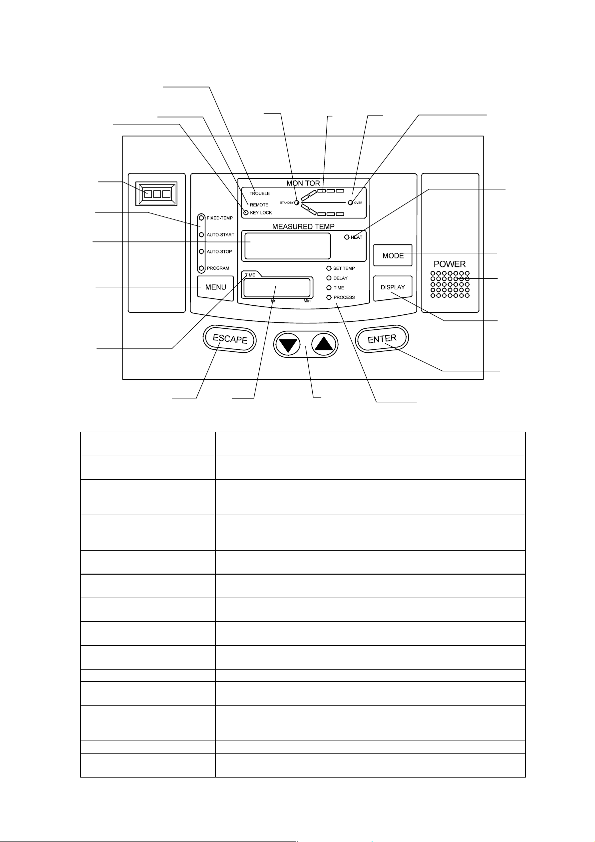
Control Panel
⑪f
⑪e
⑪
⑪
⑪b
⑪
⑯
⑫
⑨
④
⑮
⑧
⑩
⑥⑦
⑬
(1) POWER key:
(2) MODE key:
(3) DISPLAY key:
(4) MENU key:
(5) ENTER key:
(6)/(7)(UP/DOWN) key:
(8) ESCAPE key:
(9) Main Display: It displays temperature measurements, set values (temperature,
(10) Sub Display: It displays set temperature, remaining time, current hour and
(11) Operation monitor: It indicates an operation mode.
a) (11) STANDBY lamp:
b) (11) Temperature
pattern lamp:
c) (11) OVER lamp:
d) (11) TROUBLE
indicator lamp:
Key to change over the controller from the standby mode to the
operation mode or from the operation mode to the standby mode.
Key to select a function from program input, edit, delete modes,
hour/time setting, change-over mode, and other functions.
Key to change-over the display content of the sub display (10).
Display content is changed over to set temperature, remaining
time, hour, execution segment No.
Key to select the operation mode. Each mode of fixed
temperature, auto-start, auto-stop and program operation can be
selected.
Key to determine the input value of set value (temperature, time,
hour, etc.), selection mode, execution segment No. etc.
Key to change set value (temperature, time, hour, etc.) and to
choose a selection from various parameters on the function menu.
Key to cancel the latest entry and recover the status that was valid
prior to the making the latest selection.
time, hour, etc.), program information, error information, etc.
execution segment No. etc.
It flashes to indicate that the instrument is in the preoperational
standby mode.
It illuminates to indicate the heat treatment process pattern
executed by the controller with flashing light indicating the point
currently in execution.
It flashes to indicate the end of auto-stop or program operation.
It blinks when an error is detected and displays the corresponding
code for that particular problem.
5
⑭
②
①
③

e) (11)REMOTE operation
indicator lamp:
f) (11)KEY LOCK
indicator lamp:
(12) Operation menu
indicator lamp:
(13) Sub display menu
indicator lamp:
(14) HEAT ON indicator
lamp
(15) TIME indicator lamp:
(16) Independent
Temperature
Overheating Prevention
Device:
It illuminates when the instrument is put into remote operation
(optional) and displays the word “REMOTE.”
It illuminates to indicate that the operation panel key lock function is
in operation.
It illuminates to indicate the active operation mode in the operation
menu.
It illuminates to indicate the item (set temperature, remaining time,
hour or execution segment) shown in the sub display.
It illuminates when the heater is on.
It illuminates when the operation starting time of the auto-start and
the operation completion time of the auto-stop is set in the hour
setting mode.
Setting the instrument to the operational temperature of the
independent over rising prevention.
6
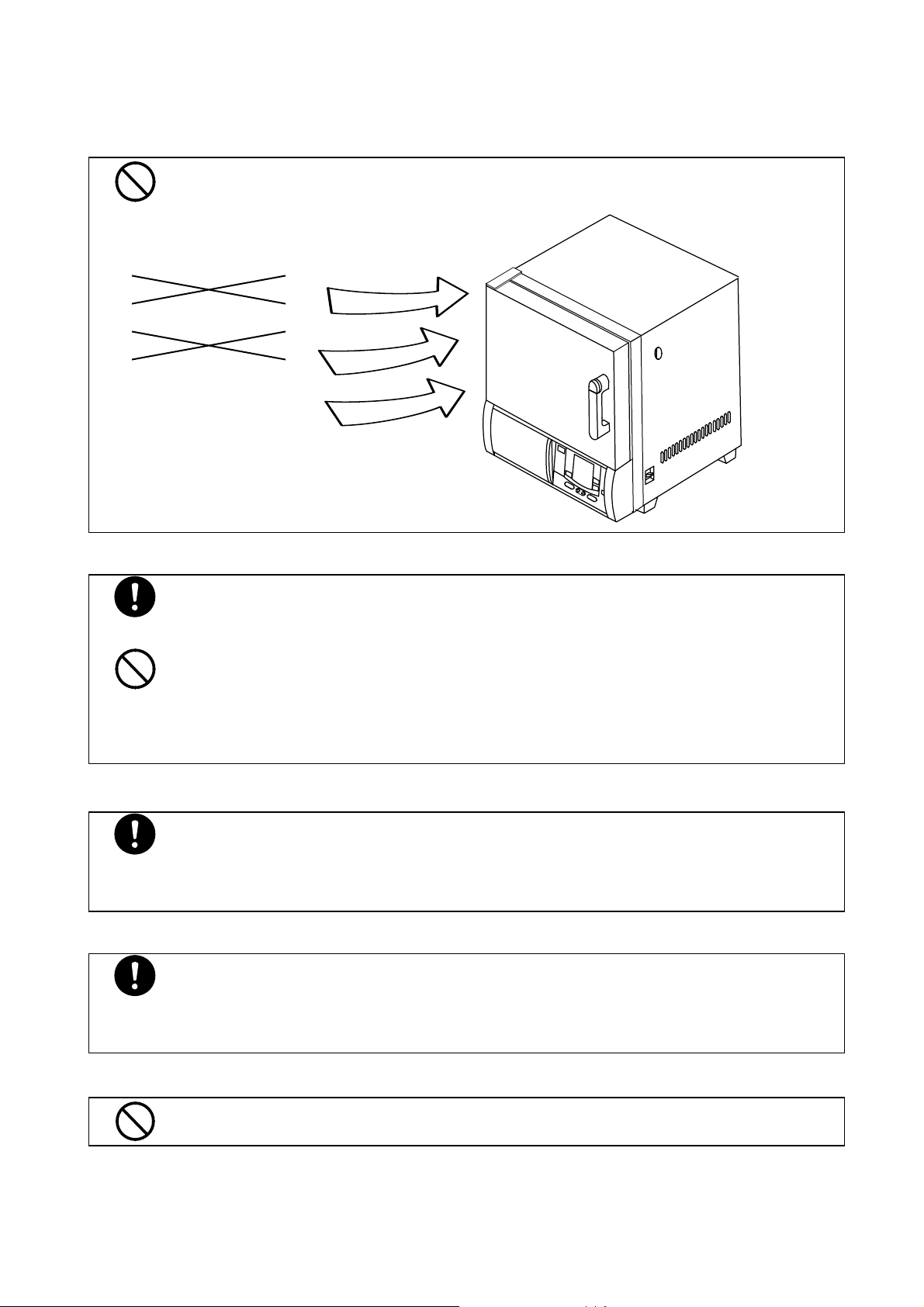
REQUIREMENTS FOR INSTALLATION
Do not use the unit in an area where there is flammable or explosive gas.
Never use the unit in an area where there is flammable or explosive gas. The unit is
not explosion-proof. An arc may be generated when the power switch is turned ON
or OFF, and fire/explosion may result.
Explosive gas
Flammable gas
Always ground the unit.
z Connect the grounding cable to your ground conductor or ground terminal.
z Do not forget to ground the Oven, to protect you and the unit from electrical shock
in case of power surge.
z Do not connect the grounding wire to a gas pipe, or by means of a lightning rod or
telephone line. A fire or electrical shock will occur.
NOTE: The oven is for the 220V use. It has not a power plug.
Choose a correct power distribution board.
z Choose a correct power distribution switchboard or receptacle that meets the
Supply connections for the oven
Install the Oven on a level area.
oven’s rated electric capacity.
Electric capacity AC 200 V, single phase 16A
z Do not connect the oven to an outlet that differs from the above specifications
because a fire or electrical shock will occur.
z Request the supply connection for the 200V specifications from a licensed
electrician.
z Failure to have this operation complete by certified personnel will cause a fire or
electrical shock during Oven operation.
z Do not installation the oven on a non level surface. This will cause hazards to the
operator and create problems during actual operation.
7

Choose a proper place for installation.
e
e
e
z Do not install the oven in a place where:
♦ Flammable gas or corrosive gas is generated.
♦ Ambient temperature exceeds 35°C.
♦ Ambient temperature fluctuates violently.
♦ There is direct sunlight.
♦ There is excessive humidity and dust.
♦ There are constant vibrations.
z Keep the following clearance around the oven.
Or mor
After installed, you should:
z It may cause injure to a person if this oven falls down or moves by the
earthquake and the impact, etc..
z To prevent, take measures that the unit cannot fall down.
z Secure the unit by putting the stoppers on the casters.
Or mor
Or mor
8
Handling of power code.
z Do not use the power cord if it is bundled or tangled. If it is used in this manner, it
can overheat and fire may be caused.
z Do not process, bend, wring, or stretch the power cord forcibly. Fire or electrical
shock may result.
z Do not put the power cord under the desk, chair, etc., or through an object. Fire
or electrical shock may be caused.
z Do not run the power cord next to heating equipment such as a heater. The
cover of the cord may melt and fire or electrical shock may result.
z When the power cord is damaged (exposure of the core wires, disconnection,
etc.), turn off the power key right immediately, then turn off the earth leakage
breaker and the main power. Contact customer service for a replacement
immediately. If this procedure is not followed, fire or electrical shock may be
caused.
Caution in setting shelves
z Do not use any shelves but the attached ones.
If it is used in this manner, the oven cannot occasionally regulate temperatures
properly.
z Put the attached shelves on the shelf brackets fitted to the chamber when you use
the oven.
9

Precautions in handling
Substances that can be used
z Never use explosive substances (shown on page 34), flammable substances
Do not put the foreign substances in the oven.
Caution in taking out samples
When you open the door during working at the high temperature.
Do not touch heated parts.
Do not climb on the oven
Do not put anything on the oven
(shown on page 34) and substances that include explosive or flammable
ingredients in the unit. Explosion or fire may occur.
Do not put a foreign substances such as metals or flammable substances in the
opening of the unit (ventilation hole and exhaust port, etc.). If this procedure is not
followed, fire, electrical shock or burn may result.
If the foreign substances enter the unit, turn off the earth leakage breaker
immediately and contact a service technician for inspection. If this procedure is not
followed, fire, electrical shock or burn may result.
During and immediately after operation, the internal surfaces of the chamber and the
door are extremely “HOT." To prevent injury, take out the samples when the
chamber has cooled down or wear gloves while the chamber is still hot.
Do not touch the internal surfaces of the chamber and the door when you will open
the door, because they are extremely hot.
To open the door while the chamber is still hot may cause the malfunction of a fire
detector if it is installed near the oven.
Do not touch the door during or immediately after operation. Severe burning injury
may be caused due to the high temperature.
Do not climb on top of the oven because it will fall down and break.
Failure to observe this caution may cause injury to a person.
Do not put anything on top of the oven because they will fall and result in injury to a
person.
10

Caution about the temperature range.
Use the oven in the range of 40°C to 210°C.
When you use the oven for the first time
During the initial operation, the oven may occasionally generate an odor especially
when high temperatures are reached. This odor is normal and does not signal a
problem with the oven. The adhesive on the insulation melting causes the nature of
the odor.
About the temperature in the chamber
Temperature display indicates the sensor temperature installed in the unit, however it
does not always correspond to the temperature of the sample when the sample
volume is very large or when the temperature is on the increase.
Caution about a drenched sample
z When using a very wet sample, try to drain it as much as possible before putting it
in chamber.
Caution about a powdery sample and the loading of samples
There are times when a powder sample is scattered by the sudden decompression
operation or purge operation. When performing decompression or purge, open the
valve very slowly.
It occasionally takes a long time before the chamber reaches the target temperature if
the camber is congested with samples or a sample with the large specific heat is in it.
In such cases, reduce samples. Moreover, note that the temperature display
occasionally unsettle when you process an exothermic sample.
Distribute samples
z Each shelf can carry a uniform load of 15 kg (33 lb.). When you place samples
on a shelf, distribute them evenly over the shelf area.
z If a shelf is congested with samples, the oven occasionally cannot regulate
temperatures properly. To ensure the oven’s temperature accuracy, there should
be open space of at least 30% on each shelf.
Never use corrosive samples
Most parts are made of stainless steel (SUS304). However, strong acid occasionally
corrodes even stainless steel. Besides this, the silicone rubber packing is also
vulnerable to acid, alkali, oil and halogens' solvents
11

Do not place any samples on the bottom of the chamber
z Do not place any samples on the bottom of the chamber to heat,
because it affects the temperature control of the oven.
z Always put the samples on the attached shelves. Place sample so that
z Set the shelves on the shelf brackets that will accommodate the size of
Sample
it does not touch the interior wall of the chamber.
the sample.
During a thunder storm
During a thunderstorm, turn off the power key immediately, then turn off the
earth leakage breaker and main power. If this procedure is not followed,
fire or electrical shock may be caused.
In case of power failure
Once the power supply has been cut off due to power failure, and then the
power supply is restored, the oven will resume running.
When you open and shut the door
Do not put your hand either face near the door when you open and shut
the door. Failure to observe this caution may result in injury because the
door hits your hand or face.
12
Operating Procedure
When prepared completely, proceed as follows:
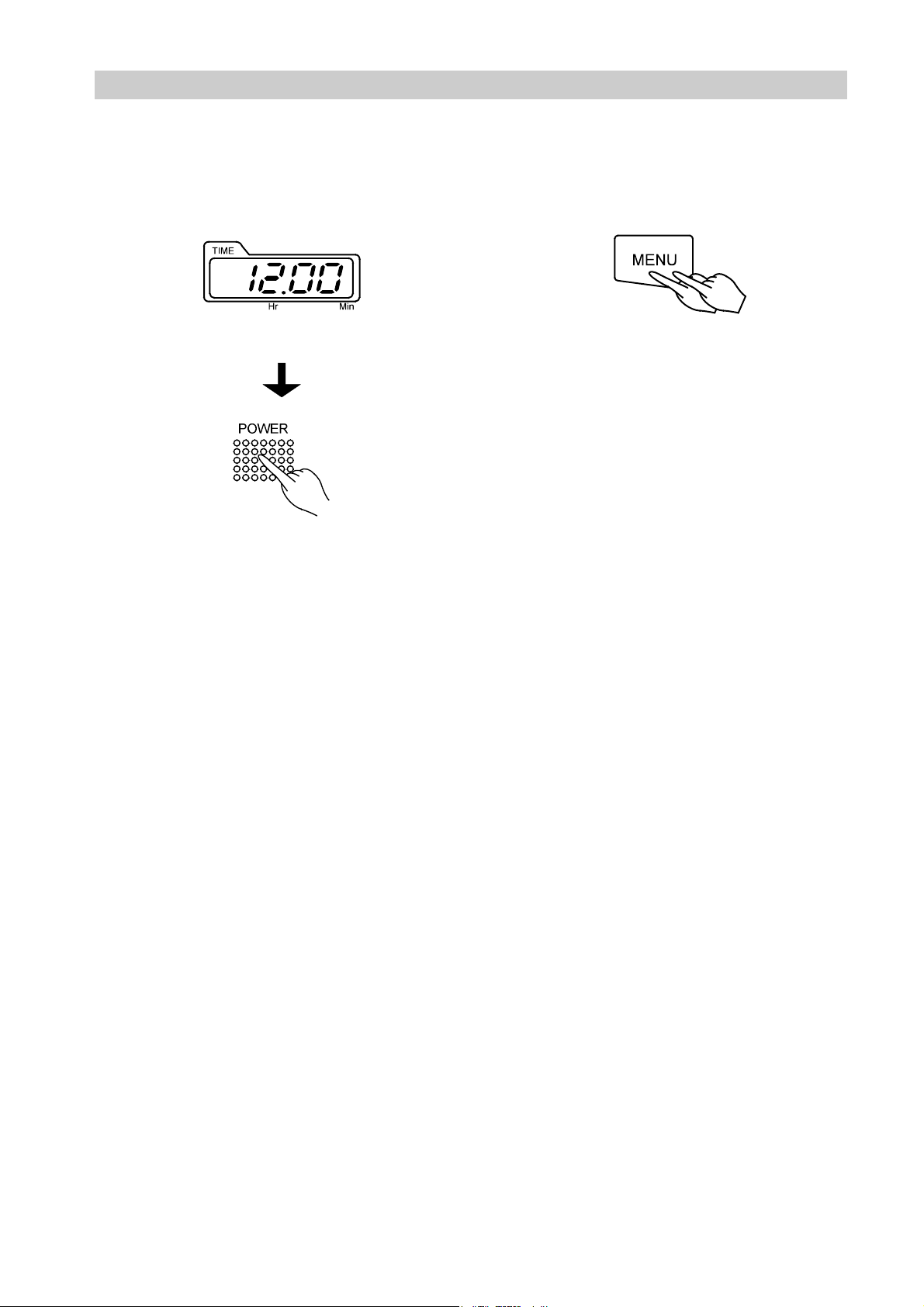
1. Turning on of power supply 2. Selection of operation menu
Turn on the earth leakage breaker. • Press the MENU key several times to select
•
desired operating method.
The present time is shown on the sub display. • It allows you to enter each parameter into a
•
flashing menu.
• Push the POWER key in the operation panel.
• When once the power is on, this oven becomes
a standby state. Under such a condition, every
operation mode can be selected by pushing the
MENU key.
3. Explanation of operation menu
Fixed
Temperature
Auto stop
Auto start
: It is an operation method to bring the oven to the desired temperature and
keep it steady.
: It is an operation method to stop a fixed temperature operation when
reached the set time or hours.
: It is an operation method to start the fixed temperature operation when
reached the set time or hours.
Program
: It is an operation method that can start or stop an operation either when
reached the set time or hours. Moreover, it can change the temperature
when reached the desired time and repeat to do that.
13

FIXED TEMPERATURE OPERATION INSTRUCTIONS
Selection of operation
menu
• Push the MENU key and
select the fixed temperature
operation.
Push the MENU key.
The lamp of the FIXED TEMP blinks.
• The temperature set last time
is blinking and enters the state
that a set temperature can be
input in a sub-display.
Input of set temperature
• Push the ENTER key after
making a sub-display display
an arbitrary set temperature
pushing ▲▼ keys.
Press either the ▲key or the ▼ key
several times.
Then, the desired set temperature will
appear on the main display.
Press the ENTER key.
• The oven will start to run the
fixed temperature operation
to the renewed temperature.
Changing the set
temperature when fixed
temp operation is in
progress
• Push either the ▲ key or
the ▼ key to display the
desired temperature on the
main display and push the
ENTER key.
Press either the ▲ key or the ▼
key several times.
Then, the desired set temperature will
appear on the main display.
Push the ENTER key.
• The oven will start to run the
fixed temperature operation
to the renewed temperature.
14

AUTO START OPERATION INSTRUCTIONS
Selection of operation menu
• Select AUTO START mode by
pushing the MENU key.
Push the MENU key.
The operation menu lamp of an AUTO
START blinks.
Inputting the set temperature
• Press either the ▲ key or
the ▼ key to display the
desired temperature on the
main display and push the
ENTER key.
Press either the ▲ key or the ▼ key
several times.
Then, the desired set temperature will
appear on the main display.
Inputting the desired set
time
• Press either the ▲ key or
the ▼ key to blink start time
(or the hour) on the main
display, and press the
ENTER key.
Press either the ▲ key or the ▼
key several times.
Then, the desired start time (or hour)
will appear on the main display.
• will appear on the
sub display and the desired
temperature can be input.
Sub display
Press The ENTER key.
Press the ENTER key.
• will appear on the
sub display and the operation
start time can be input.
• The STANDBY lamp of the
operation monitor blinks.
• The operation will be in standby
condition.
•
After reaching the set time
(or hour), the oven will start
to run the auto start
operation to the renewed
temperature.
15

Auto Stop Operation Method
Selection of operation menu
• Press the MENU key and
select the auto stop operation.
Press the MENU key.
The menu lamp of an AUTO STOP
blinks.
• will appear on the
sub display and the desired
temperature can be input.
Sub display
Inputting the set temperature
• Push either the ▲ key or
the ▼ key to blink the
desired temperature on the
main display and push the
ENTER key.
Press either the ▲ key or the ▼
key several times.
Then, the desired set temperature will
appear on the main display.
Push the ENTER key.
The main display will light up to
indicate the set temperature you have
chosen.
Inputting the desired set
time
• Push either the ▲ key or
the ▼ key to blink your
desired time (or hours) for
operation stop on the main
display, and press the
ENTER key.
Press either the ▲ key or the ▼
key several times.
Then, the desired stop time (or hour)
will appear on the main display.
Push the ENTER key.
After about 1 second
• will appear on the
sub display and the operation
stop time can be input.
• will appear on the
sub display and you can
chose the wait function to be
activated or not.
16
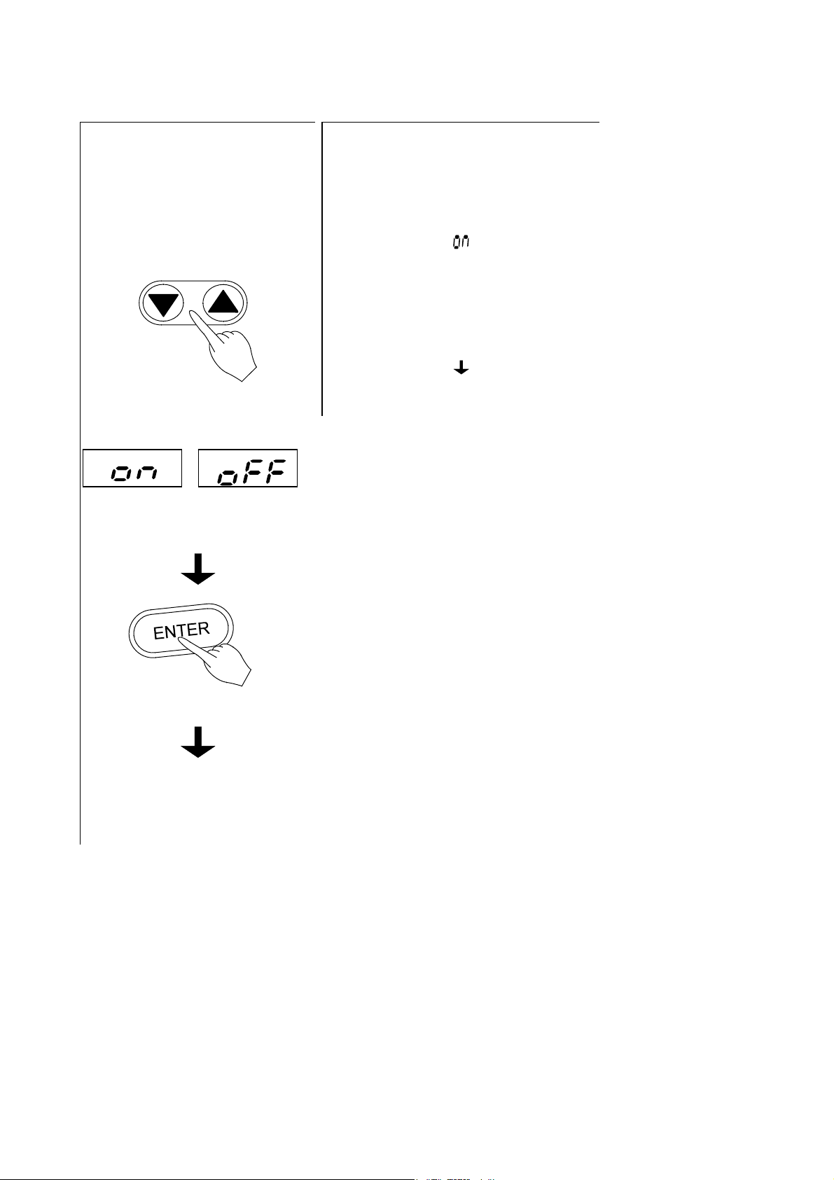
Selection of wait function
• Press either the ▲ key or the
▼ key to indicate the wait
function (ON or OFF) on the
main display. Then press
ENTER key.
Press either the ▲ key or the ▼ key
Either ON or OFF will appear on the
(activate)
several times.
main display.
(inactive)
Working conditions of timer
• Auto Stop timer activates when:
1. The wait function is on.
It starts when the set temperature has
reached the target value.
2. The waiting function is off or the time
setting represents hours.
It starts right after the auto stop
operation is started.
Press the ENTER key.
• This operation activates the
auto stop operation.
17
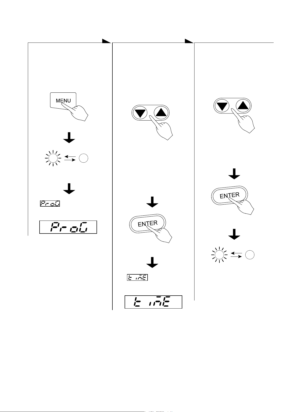
Programmed Operation Method
Selection of operation
menu
• Press the MENU key and
select the programmed
operation.
The operation menu lamp of the
PROGRAM blinks.
Press the MENU key.
Input of execution
program number
• Press either the ▲ key or
the ▼ key to indicate an
desired program number on
the main display, and press
the ENTER key.
Press either the ▲ key or the ▼ key
several times.
The program number will appear on
the main display.
NOTE: If no programs have been set,
―――― is blinking.
See the Operating Instructions
for Programmable Controller
to set a new program.
Input of time
• Press either the ▲ key or
the ▼ key to blink your
desired operation start time
(or hour) on the main display,
and press the ENTER key.
Press either the ▲ key or the ▼ key
several times.
The desired set time will appear on
the main display.
• will appear on the
sub display and the execution
program number can be input.
Push the ENTER key.
• will appear on the
sub display and the operation
start time can be input.
Push the ENTER key.
• The standby lamp on the
operation monitor blinks.
(Operation is in STANDBY
MODE)
• The operation will start after
the set time is up.
18
SWITCHING FROM ONE OPERATION TO ANOTHER
This instrument can switch to a different operation mode without stopping the current program no
matter what mode it is in, fixed temperature operation, auto-start/stop operation, and program
operation.
Selection of operation menu
• Press the MENU key several times until the
desired operation menu lamp flashes on the
Operation Menu.
• Since the current operation has not stopped, the
operation menu lamp is also lit.
• On the Operation monitor -- the temperature
pattern indicator lamp blinks with the current
segment being executed.
• This status allows you to enter each parameter
into blinking or lighting operation menu.
When the fixed temperature operation is selected
The main display shows the current internal
temperature.
The sub-display flashes the temperature set by the
previous fixed temperature operation.
When auto-start operation is selected
The main display flashes the temperature set by the
previous auto-start operation.
The sub-display shows
When auto-stop operation is selected
The main display flashes the temperature set by the
previous auto-stop operation.
The sub-display shows
When program operation is selected
The main display flashes the previously set program
number.
The sub-display shows
(Temp.)
(Temp.)
(Program) The lamp blinks or lights.
Press MENU key several times.
• Now operate according to the operation method you have chosen, see that section of this instruction
manual.
19

Method of using DISPLAY key
The display content of the sub display can be changed over by turns when pushed the DISPLAY
key.
Operation mode
Sub display
Fixed temperature
operation
Auto start
operation
Auto stop
operation
Standby
During operation
During operation
Set temperature
Hour
Remaining time
Hour
Set temperature
Remaining time (*1)
Hour
Set temperature
Remaining time (*2)
Hour
Hour
Remaining time
Hour
Set temperature
Remaining time
Hour
Hour
Program operation
After time is up
Standby
During operation
Execution segment (*3)
After finished
*1: HOLD is displayed.
*2: When the wait function is set to on, is displayed in the waiting status.
*3: The DISPLAY key will enable to show the rest of the repeat count while the repeat operation.
20

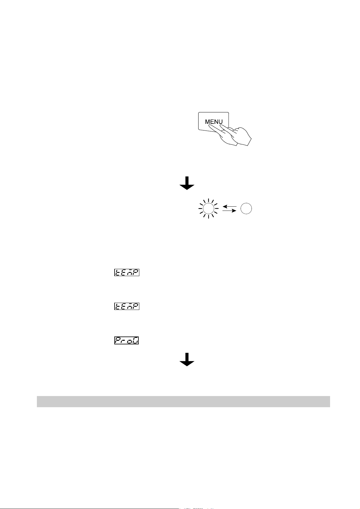
How to use the MODE
Content of function menu
This controller has the other functions shown bellow.
• Press the MODE key and display your desired
function on the main display by pushing either the
key or the key. Each function will appear by
turns whenever pushing the keys.
Main display Function
Inputting and editing
programs
Deleting the
Program.
Switching time
setting mode.
Setting and releasing
the key lock.
Alarm buzzer
ON/OFF function.
To input and edit the program.
To delete existing programs that are no longer necessary.
Confirmation of the program contents should be performed
prior to deleting and in accordance with Programmed
Operation Method.
To input either an hour or a period of time during time
setting process in the various operation modes -auto-start/stop, and program operation.
It is set to the time (a period of time) setting mode when the
product was shipped from the factory.
To set or release the key lock function.
This function is for protecting wrong key actions during the
operation or while being in the standby state.
Once set to ON, the key lock will disable you from doing
the POWER, MENU, ENTER, and DELETE key action.
If the key lock function is set, the KEY LOCK lamp on the
operation monitor is lit.
To select whether you want to activate the alarm buzzer or
not when an error occurs.
Press the mode key.
Select with the ▲ key or
the ▼ key.
Accumulating time
display function
Hold function
Date and current
hour setting function.
Calibration offset
function
To display the total duration that the POWER key is on,
within the range of 0 to 49999 hours.
To hold the operation that is currently running. This function
will get active only when you run the oven in auto-start/stop
or program operation mode (includes the standby state).
In addition, it will work when the setting of the operation
start time for auto-start and program operation as well as
the operation end time for auto-stop are set in the form of
“Time” and not in the form of “Hour.”
To set the date and hour.
To conform the display temperature to the measurement
temperature of a voluntary point in the chamber at a
voluntary temperature. Details are described on page 22
21
 Loading...