

Page 1

g
Forced Convection
Constant Temperature Drying Oven
Model
DKN 302/402/602
612/812/912
Instruction Manual
- First Edition -
z Thank you for purchasing "Forced Convection
Constant Temperature Drying Oven, DKN
Series" of Yamato Scientific Co., Ltd.
z To use this unit properly, read this "Instruction
Manual" thoroughly before using this unit.
Keep this instruction manual around this unit for
referring at anytime.
WARNING!:
Carefully read and thoroughly understand the
important warning items described in this
manual before usin
this unit.
Yamato Scientific Co. LTD.
Page 2

Page 3

Contents
Cautions in Using with Safety................................................................1
Explanation....................................................................................................................1
•
•
Table of Illustrated Symbols ..........................................................................................2
•
Fundamental Matters of "WARNING!" and "CAUTION!"............................................... 3
Before Using this unit.............................................................................4
• Requirements for Installation.........................................................................................4
Description and Function of Each Part.................................................9
Main Unit.......................................................................................................................9
•
•
Control Panel...............................................................................................................12
•
Characters of the Controller........................................................................................ 13
Operation Method .................................................................................14
• Operation Mode and Function List.............................................................................. 14
•
Operation Mode, Function Setting Key, and Characters.............................................16
•
Setting of Overheating Prevention Device ..................................................................17
•
Fixed Temperature Operation...................................................................................... 18
•
Quick Auto Stop Operation..........................................................................................19
•
Auto Stop Operation.................................................................................................... 20
•
Auto Start Operation....................................................................................................22
•
Program Operation......................................................................................................24
•
Other Functions........................................................................................................... 31
Handling Precautions ...........................................................................32
Maintenance Method.............................................................................34
Daily Inspection and Maintenance ..............................................................................34
•
Long storage and disposal...................................................................35
When not using this unit for long term / When disposing............................................35
•
In the Event of Failure….......................................................................36
• Safety Device and Error Code..................................................................................... 36
•
Trouble Shooting......................................................................................................... 37
After Service and Warranty ..................................................................38
Specification..........................................................................................39
Wiring Diagram......................................................................................40
Replacement Parts Table......................................................................44
Reference...............................................................................................45
• List of Dangerous Substances ....................................................................................45
Page 4

Page 5
Explanation
Illustrated Symbols
Various symbols are used in this safety manual in order to use the unit without
danger of injury and damage of the unit. A list of problems caused by ignoring
the warnings and improper handling is divided as shown below.Be sure that you
understand the warnings and cautions in this manual before operating the unit.
Cautions in Using with Safety
MEANING OF ILLUSTRATED SYMBOLS
WARNING!
CAUTION!
If the warning is ignored, there is the danger of a problem that
may cause a serious accident or even fatality.
If the caution is ignored, there is the danger of a problem that may
cause injury/damage to property or the unit itself.
Meaning of Symbols
This symbol indicates items that urge the warning (including the caution).
A detailed warning message is shown adjacent to the symbol.
This symbol indicates items that are strictly prohibited.
A detailed message is shown adjacent to the symbol with specific actions not to
perform.
This symbol indicates items that should be always performed.
A detailed message with instructions is shown adjacent to the symbol.
1
Page 6

Table of Illustrated Symbols
Warning
Cautions in Using with Safety
Warning,
generally
Caution
Caution,
generally
Caution,
water only
Warning,
high voltage
Caution,
electrical shock
Caution,
deadly poison
Warning,
high temperature
Caution,
Warning,
drive train
Caution,
scald
no road heating
Warning,
explosive
Caution,
not to drench
Prohibit
Prohibit,
generally
Compulsion
Compulsion,
generally
inflammable
Compulsion,
connect to the
Prohibit,
grounding
terminal
to disassemble
Compulsion,
install on a flat
Prohibit,
surface
Prohibit,
to touch
Compulsion,
disconnect the
power plug
Compulsion,
periodical
inspection
2
Page 7

Cautions in Using with Safety
Fundamental Matters of "WARNING!" and "CAUTION!"
WARNING!
Do not use this unit in an area where there is flammable or explosive gas
Never use this unit in an area where there is flammable or explosive gas. This unit is not
explosion-proof. An arc may be generated when the power switch is turned on or off, and
fire/explosion may result. (Refer to page 45 "List of Dangerous Substances".)
Always ground this unit
Always ground this unit on the power equipment side in order to avoid electrical shock due to a power
surge.
If a problem occurs
If smoke or strange odor should come out of this unit for some reason, turn off the power key right
away, and then turn off the circuit breaker and the main power. Immediately contact a service
technician for inspection. If this procedure is not followed, fire or electrical shock may result. Never
perform repair work yourself, since it is dangerous and not recommended.
Do not use the power cord if it is bundled or tangled
Do not use the power cord if it is bundled or tangled. If it is used in this manner, it can overheat and
fire may be caused.
Do not process, bend, wring, or stretch the power cord forcibly
Do not process, bend, wring, or stretch the power cord forcibly. Fire or electrical shock may result.
Substances that can not be used
Never use explosive substances, flammable substances and substances that include explosive or
flammable ingredients in this unit. Explosion or fire may occur. (Refer to page 45 "List of Dangerous
Substances".)
Do not disassemble or modify this unit
Do not disassemble or modify this unit. Fire or electrical shock or failure may be caused.
Do not touch high-temperature parts
The inside of the body or the door may become hot during and just after operation. It may cause burns.
CAUTION!
During a thunder storm
During a thunderstorm, turn off the power key immediately, then turn off the circuit breaker and the main
power. If this procedure is not followed, fire or electrical shock may be caused.
3
Page 8

Requirements for Installation
Before Using this unit
WARNING!
1. Always ground this unit
• The DKN302, DKN402and DKN602 types use a 100V power so urce.
• The DKN612, DKN812 and DKN912types use a single-p hase 200V power source. Please
consult your local electrical contractor for power connecting work.
• Be sure to connect the earth wire (the green cable of power cord) to the grounding conductor
or ground terminal to prevent accidents caused by electric leakage.
• Do not connect the earth wire to gas or water pipes. If not, fire disaster may be caused.
• Do not connect the earth wire to the ground for telephone wire or lightning conductor. If not,
fire disaster or electric shock may be caused.
• Do not use a branching receptacle, which may cause the heat generation.
2. Choose a proper place for installation
• Do not install this unit in a place where:
♦ Rough or dirty surface.
♦ Flammable gas or corrosive gas is generated.
♦ Ambient temperature exceeds 35°C.
♦ Ambient temperature fluctuates violently.
♦ There is direct sunlight.
♦ There is excessive humidity and dust.
♦ There is a constant vibration.
• Install this unit on a stable place with the space as shown below.
The exhausted opening is provided at the top surface of unit for DKN302, DKN402, DKN602
and DKN612 types, and at the back surface for DKN812 and DKN912 types.
More than
15cm
More than 30cm
Main Unit
Front side
More than
15cm
4
Page 9
Before Using this unit
Requirements for Installation
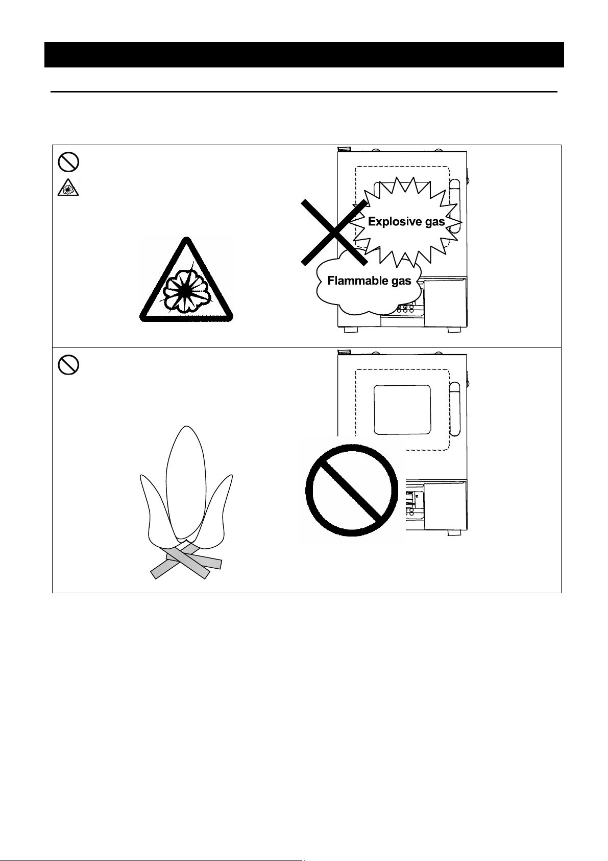
3. Do not use this unit in an area where there is flammable or explosive gas
(Refer to page 45 "List of Dangerous Substances".)
• Never use this unit in an area where
there is flammable or explosive gas.
This unit is not explosion-proof. An
arc may be generated when the
power switch is turned ON or OFF,
and fire/explosion may result.
• Never use explosive sub s tances,
flammable substances and
substances that include explosive or
flammable ingredients in this unit.
Explosion or fire may occur.
Flammable
substance
5
Page 10
Before Using this unit
Requirements for Installation
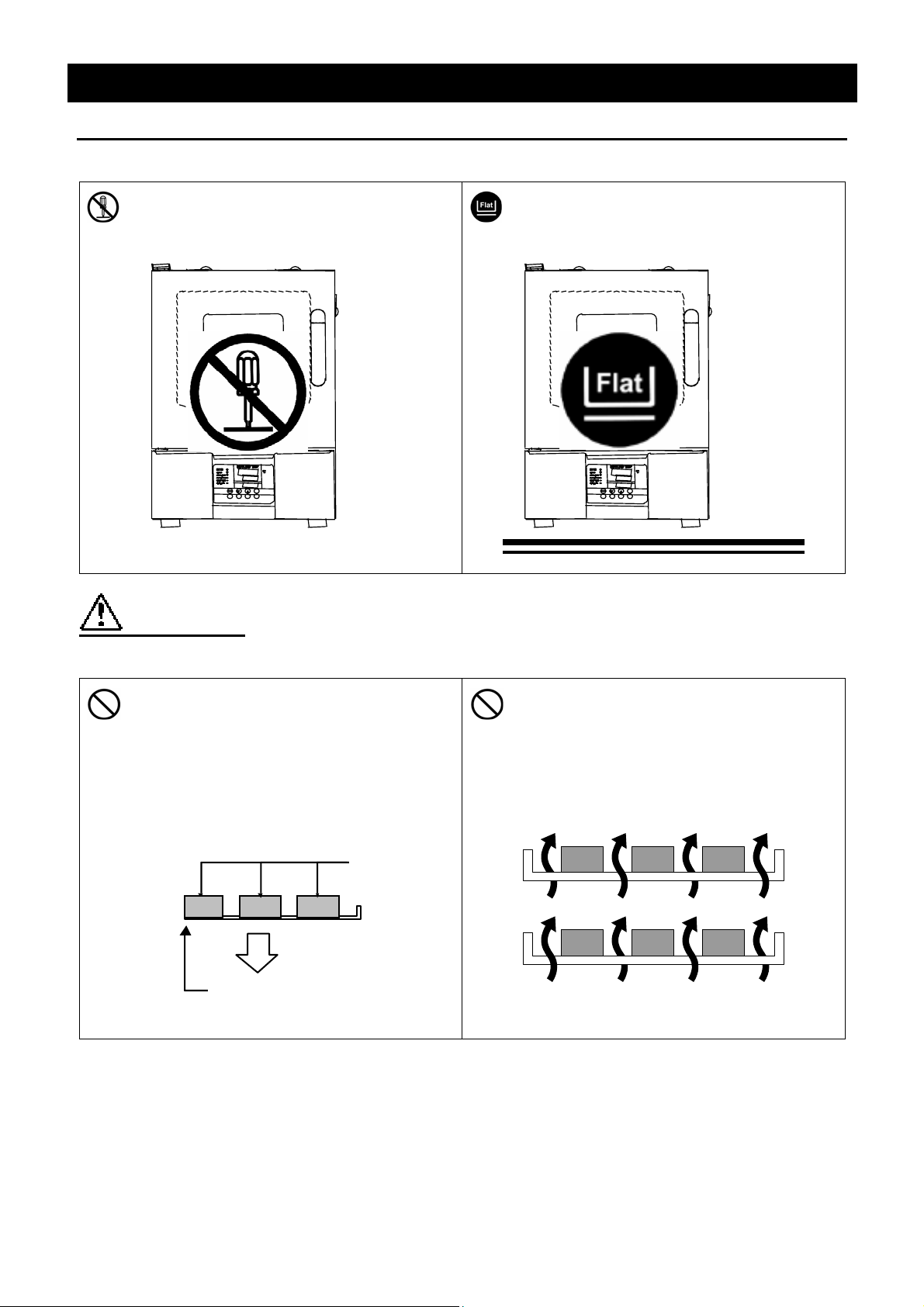
4. Do not modify 5. Installation on horizontal surface
• Modification of this unit is strictly
prohibited. This could cause a failure.
Do not modify To the flattest place
• Set this unit to the flattest place. Setting
this unit on rough or slope place could
cause the vibration or noise, or cause the
unexpectible trouble or malfunction.
CAUTION!
6. Do not make an overload 7. Do not set samples in close formation
• The withstand load of shelf is 15kg
(uniform load)Set the samples apart
each other.
Samples
15Kg
Shelf
• The temperature in furnace cannot be
controlled if too much samples are set
there. Make sure to use the shelf and
set samples apart each other so as to
make the free space of 30% or more to
the furnace to acquire accuracy of
temperature.
Make the free space of 30% or more
6
Page 11

Before Using this unit
Requirements for Installation
8. Choose a correct power distribution board or receptacle
• Choose a correct power distribution board or receptacle that meets the unit’s rated electric
capacity.
Electric capacity:
NOTE)
There could be the case that the unit does not run even after turning ON the power. Inspect
whether the voltage of the main power is lowered than the specified value, or whether other
device(s) uses the same power line of this unit. If the phenomena might be found, change the
power line of this unit to the other power line. Please consult your dealer or a local electrical
contractor for the connection of devices that use a single-phase 200V power source.
9. Before/after installing
• It may cause injure to a person if this unit falls down or moves by the earthquake and the
impact. etc..To prevent, take measures that the unit cannot fall down, and not install to busy
place.
• Touching the unit may cause a burn during and just after the operation. To prevent, take
measures that putting up a notice of operating etc..
• Make sure to lock the caster for DKN812and DKN912 types.
DKN302: 100V AC, 8.5A
DKN402: 100V AC, 12.5A
DKN602: 100V AC, 14A
DKN612: 1φ200V AC, 8A
DKN812: 1φ200V AC, 12.5A
DKN912: 1φ200V AC, 15.5A
10. Setting of the shelf and sample
• D The number of shelves attached varies depending on the type of product (2 to 8).One of
them (two for DKN912 ) is previously fixed on the lowermost stand of bracket supporter with
screws at factory shipment. Set the other shelves in place in furnace as necessary.
• One of the shelves is fixed on the lowermost stand of bracket supporter with screws at factory
shipment.The temperature of current plate and its adjacence is usually higher than the setting
temperature because a heater is provided under it, which may cause burn of sample or fire
disaster if a sample is directly put on the current plate. To prevent such accidents, the shelf
is fixed with screws as shown in the figure. Be sure to provide sufficient space between the
current plate and sample in case the shelf must be removed due to the shape of sample. Do
not put the sample directly on the current plate.
Bracket supporter
M4 screw
Bracket
Shelf
Never use explosive substances,
flammable substances and
substances that include explosive
or flammable ingredients in this
Current plate
7
Page 12
Requirements for Installation
11. Handling of power code
• Do not entangle the power cord. This will cause overheating and possibly a fire.
• Do not bend or twist the power cord, or apply excessive tension to it. This may cause a fire
and electrical shock.
• Do not lay the power cord under a desk or chair, and do not allow it to be pinched in order to
prevent it from being damaged and to avoid a fire or electrical shock.
• Keep the power cord away from any heating equipment such as a room heater. The cord's
insulation may melt and cause a fire or electrical shock.
• If the power cord becomes damaged (wiring exposed, breakage, etc.), immediately turn off the
power at the rear of this unit and shut off the main supply power. Then contact your nearest
dealer for replacement of the power cord. Leaving it may cause a fire or electrical shock.
• Connect the power plug to the receptacle which is supplied appropriate power and voltage.
Before Using this unit
8
Page 13

Main Unit
DKN302/402/602/612
Front view
Door
Glass window
Description and Function of Each Part
Exhausted opening
Cable port
Production plate
Door handle
Rear view
Power cord
Control panel
Main switch
(Earth leakage breaker)
DKN612のみ
9
Page 14

Main Unit
DKN812
Front view
Door
Description and Function of Each Part
Control panel
Main switch
(breaker)
Cable port
Production plate
Door handle
Rear view
Exhausted opening
Power cord
Caster
10
Page 15

Main Unit
DKN912
Front view
Description and Function of Each Part
Control panel
Main switch
(Earth leakage breaker)
Cable port
Production plate
Rear view
Door handle
Door
Caster
Exhausted opening
Power cord
11
Page 16

Control Panel
Description and Function of Each Part
⑧
⑨
⑩
⑪
⑫
⑬
③
②
④
⑤
① START/STOP Key:
② ▲▼ Key:
③ ENTER Key:
④ FIXED TEMP Key:
⑤ TIMER Key:
⑭
POWER
⑮
⑯
⑰
①
⑱
⑦
Starts/stops the operation.
Uses for rising UP/lowering DOWN the setting value.
Settles the inputted value.
Chooses the fixed temperature operation.
Chooses the timer operation (Quick Auto Stop/Auto Stop/Auto
Start).
⑥
⑥ PROGRAM Key:
⑦ SUBMENU Key:
⑧ HEATER Lamp:
⑨ ALARM Lamp:
⑩ AUTO STOP Lamp:
⑪ AUTO START Lamp:
⑫ FIXED TEMP Lamp:
⑬ PROGRAM Lamp:
Measurement Temperature
⑭
Display:
Setting Temperature
⑮
Display:
Overheating Prevention
⑯
Temperature Display:
Chooses the program operation or program creation mode.
Uses for setting the overheating prevention temperature,
calibration offset temperature, key lock function, or program
repeat function.
Lights while the heater works.
Lights up when an error occurs. (Buzzer sounds simultaneously.)
Blinks while setting quick auto stop timer or auto stop timer.
Lights while quick auto stop timer or auto stop timer is running.
Blinks while setting auto start timer.
Lights while auto start timer is running.
Blinks while setting fixed temperature operation.
Lights while fixed temperature operation is running.
Blinks while setting program operation.
Lights while program operation is running.
Displays the measured temperature, setting character, alarm
information.
Displays the setting temperature, setting value for timer mode,
remaining time.
Displays the setting temperature for overheating prevention
device.
Power Switch:
⑰
(Earth leakage breaker)
⑱ Electric leak testing button:
Turns ON/OFF the main power.
Checks the breaker’s condition.
12
Page 17

Description and Function of Each Part
Characters of the Controller
The characters VS4 controller shows are as follows:
Character Identifier Name Purpose
FiX
Sv
AStP
AStr
tim
PrG3
PAt
End
Sv-1
Fixed Temperature
Setting Mode
Temperature Setting
Timer Setting Mode
Display
Timer Setting Mode
Display
Time Setting
Program Type
Program Pattern
Time Up
Program Temperature
Setting
Used for starting the fixed temperature
operation.
Used for setting the temperature.
Represents the setting of quick auto stop or
auto stop operation.
Represents the setting of auto start
operation.
Used for setting the time.
Used for choosing program type from 1 to 3.
(Refer to Page 24 " Program Operation".)
Used for choosing program pattern. (Refer to
Page 24 " Program Operation".)
Displays when the timer operation is
completed or while inputting number of
program steps. (Refer to Page 24 " Program
Operation".)
Used for setting the temperature for each
step in the program. (Sv-1 to Sv-30 is
shown.)
t-1
PS-3
Pc-2
cAL
oH
LocK
* Also refer to Page 16 "Operation Mode, Function Setting Key, and Characters".
Program Time Setting
Step Number to be
Repeated
Repeating Times
Calibration Offset
Setting
Overheating Prevention
Setting
Key Lock
Used for setting the time for each step in the
program. (t-1 to t-30 is shown.)
Used for choosing the step number to be
repeated under the program operation with
repeat function. (Refer to Page 28 " Use
program repeat function".)
Used for setting the repeating times under
the program operation with repeat function.
(Refer to Page 28 " Use program repeat
function".)
Used for inputting the calibration offset
temperature. (Refer to Page 31 "Other
Function".)
Used for setting temperature for overheating
prevention device. (Refer to Page 17 "Setting
of Overheating Prevention Device ".)
Locks the keys on control panel to protect
from unnecessary operation. (Refer to Page
31 "Other Function".)
13
Page 18

Operation Method
Operation Mode and Function List
All the operation mode of this unit is as follows;
No. Name Description Page
Pressing the FIXED TEMP key enters into the fixed
Fixed Temperature
1.
Operation
Quick Auto Stop
2.
Operation
temperature operation setting mode.
Pressing it again enters into the temperature setting mode.
The "
▲▼" are used to set temperature.
Pressing the START/STOP key starts or stops operation.
This operation is used to specify the period up to automatic
stop during operation.
The period up to operation stop can be set by pressing the
TIMER key during fixed temperature operation.
The "
▲▼" are used to set the time.
Pressing the START key starts the quick auto stop
operation, activates the timer function and stops the
operation automatically after specified period.
18
19
3. Auto Stop Operation
4. Auto Start Operation
5. Program Operation
This operation is used to specify the automatic stop time in
the fixed temperature operation.
Pressing the TIMER key displays "AS
The setting temperature "SV" can be set by pressing the
ENTER key.
The operation time "tim" can be set by pressing it again.
Pressing the START/STOP key starts the auto stop
operation.
This operation is used to specify the period up to automatic
start after power on.
Pressing the TIMER key displays "AS
The setting temperature "SV" can be set by pressing the
ENTER key.
The operation time "tim" can be set by pressing it again.
Pressing the START/STOP key starts the auto start
operation.
This operation is used to change the temperature according
to the setting temperature and time.
Pressing the PROGRAM key displays "PrG1".
Press it again to select the program mode.
Press the ENTER key to select the pattern "PA t".Press the
ENTER key to display "End". Input the number of
patterns to be used.
Input the temperature and time of patterns "SV-n" and "t-n"
respectively.
tp".
tr".
20
22
24
NOTE) This unit is impossible to be changed the mode during the operation. If the mode requires to be
changed, stop the operation.
14
Page 19

Operation Method
Operation Mode and Function List
The operation function of this unit is as follows;
No. Name Description Page
Auto overheating
prevention function
Overheating
1.
prevention
function
2. Calibration offset function
Overheating prevention
3.
temperature calibration
function
Overheating
prevention device
This function is set to be automatically activated
(auto reset) when the temperature exceeds the
setting temperature by 12
Though the device shares power source, display,
and key input with the controller, it has
independent temperature measurement circuit,
CPU, sensor and output circuit. Overheating
prevention temperature can be set using the
operation panel.
The unit stops operation when the device is
activated. The unit starts operation again when
the POWER switch is pressed again (manual
reset).
This calibration offset function is for calibrating
the difference occurred between the required infurnace temperature and control temperature
(sensor temperature) of the controller. This unit
can be calibrated toward either plus side or minus
side of the whole temperature range.
The temperature of overheating prevention device
is automatically corrected when the temperature
of controller is collected.
℃.
17
31
-
4. Recovery at power failure
5. Setting value locking
The unit starts operation with the same condition
as just before power failure if it occurs during
operation. Press the START/STOP key to start
the unit again.
This function locks the established operation
status.
It can be set and cancelled with the SUBMENU
key.
-
31
15
Page 20

Operation Method
Operation Mode, Function Setting Key, and Characters
The operation mode setting and function setting use the key operation and characters show in
the following figure.
16
Page 21

Operation Method
Setting of Overheating Prevention Device
The unit has the overheating prevention device (manual reset) that consists of independent
temperature measurement circuit, CPU, sensor and output circuit (it shares power source, display,
and key input with the controller) in addition to the automatic overheating prevention function
(auto reset) in the controller.
Setting range/function
The unit has failsafe functions against overheating. One of them is built in the controller and previously
set at factory shipment so to be automatically activated when the temperature exceeds the setting
temperature of temperature controller by 12℃, where the heater repeats on and off.
The other is united with the controller, which can be set by operating the keys on the controller .
The setting range of latter is from 0℃ to max set temperature of main controller + 50℃.
In case the temperature in furnace exceeds the setting temperature of controller to reach to that of
overheating prevention device, the circuit is shut off and "Er19" is displayed with blinking on the screen of
controller with buzzer sound.
If the device is once activated,"Er19"continues to be displayed until the power is newly turned o n.
Temperature setting procedure
Notes:
• The standard setting temperature of device is "the maximum setting temperature of unit plus
20℃" or "setting temperature plus 20℃". If the unit performs improper operation, increase it
5℃ more.
• The setting range of overheating prev ention device is from 0℃ to max set temperature of
main controller + 50℃. Improper setting of temperature may cause inoperative of unit,
malfunction of device, e.g. it is activated during increasing in temperature in furnace, or
unexpected accidents such as fire disaster. To prevent such matters, set a proper value.
The temperature is set to 290℃ at factory shipment. Do not set the value larger than
it.
• In some case, the overheating prevention device is possible to be activated by mistake when
its yield temperature is set to around room temperature.
• The purpose of overheating preventio n device is to protect the unit from overheating. It does
not intend to protect the samples, or to protect them from the accident caused by the use of
explosive or inflammability.
1. Turn on the power (turn on the breaker in front)
• The default value is displayed for about four seconds after
turning on the power. The screen then displays the initial
setting. The current temperature in furnace, operation
mode character and setting temperature of overheating
prevention device are displayed on respective screens.
2. Set the temperature for overheating prevention
① Press the SUBMENU key.
② Press the " ▼▲" several times to select the setting
character of overheating prevention temperature "OH".
③ Press the ENTER key. The current setting temperature is
displayed with blinking on the setting temperature screen.
Note: To prevent improper operation, set the value 10℃ or more
over the setting temperature of controller .
④ Select the value using the "▼▲"and then press the
ENTER key. This completes the setting.
17
Page 22

Fixed Temperature Operation
Operation Method
Fixed temperature
operation procedure
1. Turn on the power (turn on the breaker in front)
The default value is displayed for about four seconds after turning
on the power. The screen then displays the initial setting. The
current temperature in furnace, operation mode character and
setting temperature of overheating prevention device are displayed
on respective screens.
Measurement temperature screen:
Displays the current temperature in furnace.
Setting temperature screen:
Displays the operation mode character. (Refer to Page 13)
Overheating prevention screen:
Displays the setting temperature of overh eating prevention device
2. Select the operation mode
• Press the FIXED TEMP key to display "FIX", which indicates the
fixed temperature operation, on the center display screen.
3. Set the temperature
• Press the FIXED TEMP key again.
• The setting temperature screen displays the character "SV"
which indicates the temperature setting. Also it displays the
current setting temperature with blinking. The FIXED TEMP
lamp blinks, too.
• Set the temperature by pressing the "▼▲".
4. Start operation
• Press the orange START/STOP key for about one second. The
unit starts operation and the blinking FIXED TEMP lamp lights
on.
5. Stop operation
• Press the orange START/STOP key for about one second. The
unit stops operation and the FIXED TEMP lamp lights off. The
screen returns to the initial setting screen.
To correct or check setting…
Press the FIXED TEMP key again to correct or check the setting.
Changing the setting temperature during operation is also possible by pressing the FIXED TEMP key.
18
Page 23

Quick Auto Stop Operation
Operation Method
Quick auto stop
operation procedure
Timer function:
This operation is used to specify the period up to automatic stop,
i.e., sets the auto stop timer during operation.
1. Set the time up to stop during fixed temperature operation
• Check that the FIXED TEMP lamp lights on and that the unit is
under operation.
• Press the TIMER key.
• The measurement temperature display screen displays the
character "tim", which indicates the timer setting. The setting
temperature display screen displays the current setting time with
blinking.
• Select the time by pressing the "▼▲".
• The maximum setting time is "999hours and 50 minutes ".
• The time can be set in increments of a minute under 99 hours
and 59 minutes.
• It can be set in increment of ten minutes over 100 hours.
• The "▼▲"can change the setting time quickly when it is pressed
continuously. Press them discontinuously when fine adjustment
is needed.
2. Start timer operation
• Press the START/STOP key for one second after deciding the
time.
• Timer operation starts with the FIXED TEMP and AUTO STOP
lamps lighting on.
• The timer is activated at the point when the START/STOP key is
pressed.
3. Stop/terminate timer operation
• The operation stops automatically at setting time.
• Buzzer continues to sound for about five minutes at operation
stop.
• The setting temperature screen displays the character "End",
which indicates termination of operation, with the FIXED TEMP
and AUTO STOP lamps lighting on. Press the START/STOP
key to terminate the timer operation mode. The screen returns
to the initial setting screen.
To correct or check setting…
Changing the setting temperature during operation is possible by pressing the FIXED TEMP key. Press
the ENTER key after changing the setting.
Changing the setting temperature during operation is available by pressing the FIXED TEMP key. Press
the ENTER key after changing the setting.
Press the ▼ key to display the setting temperature, operation mode and residual time on the setting
temperature screen.
19
Page 24

Auto Stop Operation
Operation Method
Auto stop operation
procedure
Timer function:
This operation is used to specify the automatic stop time in the
fixed temperature operation.
1. Set stop time
① Press the TIMER key on the initial screen.
Press the TIMER key again. The setting temperature display
screen displays the character "AstP", which indicates the auto
stop operation, with blinking.
② Press the ENTER key.
The measurement temperature screen displays the character
"SV", which indicates the temperature setting. The setting
temperature screen displays the current setting temperature with
blinking. The AUTO STOP lamp blinks, too.
③ Set the temperature us ing the "▼▲".
④ Press the ENTER key again.
The measurement temperature display screen displays the
character "tim", which indicates the timer setting. The setting
temperature display screen displays the current setting time with
blinking.
⑤ Set the time using the "▼▲".
• The maximum setting time is "999hours and 50 minutes ".
• The time can be set in increments of a minute under 99 hours
and 59 minutes.
• It can be set in increment of ten minutes over 100 hours.
• The "▼▲"can change the setting time quickly when it is pressed
continuously. Press them discontinuously when fine adjustment
is needed.
2. Start timer operation
• Press the START/STOP key for one second after deciding the
time.
• Timer operation starts with the AUTO STOP lamp lighting on.
• The timer is activated at the point when the temperature in
furnace (measurement temperature) reaches to the setting
temperature.
20
Page 25

Operation Method
Auto Stop Operation
To correct or check setting…
Changing the setting temperature or time during operation is possible by pressing the TIMER key. Use
the "▼▲" to change the setting value. Press the ENTER key respectively after changing the setting.
Press the "▼" to display the setting temperature, operation mode and residual time on the setting
temperature screen.
3. Stop/terminate timer operation
• The operation stops automatically at setting time.
• Buzzer continues to sound for about five minutes at operation
stop.
• The setting temperature screen displays the character "End",
which indicates termination of operation, with the FIXED TEMP
and AUTO STOP lamps lighting on. Press the START/STOP
key to terminate the timer operation mode. The screen returns
to the initial setting screen.
21
Page 26

Auto Start Operation
Operation Method
Auto start operation
procedure
Timer function:
This operation is used to specify the period up to automatic start
after power on.
1. Set start time
① Press the TIMER key on the initial screen.
Press the TIMER key again. The setting temperature display
screen displays the character "Astr", which indicates the auto start
operation, with blinking.
② Press the ENTER key.
The measurement temperature screen displays the character
"SV", which indicates the temperature setting. The setting
temperature screen displays the current setting temperature with
blinking. The AUTO START lamp blinks, too.
③ Set the temperature us ing the "▼▲".
④ Press the ENTER key again.
The measurement temperature display screen displays the
character "tim", which indicates the timer setting. The setting
temperature display screen displays the current setting time with
blinking.
⑤ Set the time using the "▼▲".
• The maximum setting time is "999 hours and 50 minutes ".
• The time can be set in increments of a minute under 99 hours
and 59 minutes.
• It can be set in increment of ten minutes over 100 hours.
• The "▼▲"can change the setting time quickly when it is pressed
continuously. Press them discontinuously when fine adjustment
is needed.
2. Start timer operation
• Press the START/STOP key for one second after deciding the
time.
• Timer operation starts with the AUTO START lamp lighting on.
22
Page 27

Operation Method
Auto Start Operation
To correct or check setting…
Changing the setting temperature or time during operation is possible by pressing the TIMER key. Use
the "▼▲" to change the setting value. Press the ENTER key respectively after changing the setting. They
are not changeable after the unit starts operation. In this case, stop the operation by pressing the
START/STOP key, then set the value again.
Press the "▼" to display the setting temperature, operation mode and residual time on the setting
temperature screen.
3. Stop/terminate timer operation
• The operation starts automatically at setting time.
• Press the START/STOP key for one second to stop or terminate
operation. The screen returns to the initial setting screen.
23
Page 28

Operation Method
Program Operation
This operation is used to change the temperature according to the setting temperature and time.
Program types
Temp.
Six patterns of program types maximum can be input.
PrG1 - 1 program pattern using 30 steps maximum can be created.
PrG2
PrG3
PAt1
PAt2
PAt1
PAt2
PAt3
2 program patterns using 15 steps maximum can be created.
3 program patterns using 10 steps maximum can be created.
△ Stop △ Start
Time
Before inputting program…
Input program patterns before program operation.
① Check the number of steps in a created program and their setting temperature/time. Use the
program preparation sheet in pages 29 and 30 to check.
② Check the temperature rise/fall capability of the unit. Set the time within the capability above.
Suppose, for instance, that in the unit which has capability of increasing or decreasing
temperature by 50℃ within 30 minutes, about 30 minutes is needed to increase or decrease
temperature by 100℃ from current temperature
Repeat function:
Repeat function is useful in case the operation uses the program repeating the same program
steps. Refer to page28 for the function.
③ Check if the controller has sufficient free pattern for the number of steps to be created. The steps,
however, using the repeat function mentioned above are not counted.
Temperature fall/rise curve for DKN type
The temperature fall curve and temperature rise curve for DKN type are shown below.
The numeric value indicates the necessary time between temperatures (ex: about 15 minutes is
needed to increase temperature from 100
after reaching to the setting temperature is necessary to be added. Make sure to conduct a test
run before setting the optimum time.
Condition: room temperature 23
260℃
200℃
150℃
100℃
50℃
DKN302 DKN402
Rise Fall Rise Fall Rise Fall Rise Fall Rise Fall
20 - 20 - 25 - 20 - 25 15 20 20 20 20 20 15 20 25 30
10 15 15 20 15 20 10 25 20 30
10 20 15 30 15 30 10 40 20 60
5 45 5 60 5 75 5 120 5 180
℃, no load, exhaust opening fully opened (unit: minute)
℃ to 150℃ for DKN602). Temperature stability time
DKN602
/612
DKN812 DKN912
24
Page 29

Operation Method
Program Operation
Program creation
The program pattern below is explained as an example.
1. Program pattern example
Temp.
200℃
100℃
0℃
Step 1 2 3 4 5 6 7 8 9
Temp.(℃)
Time(min.)
100 100 150 150 200 200 50 50 25
25 30 15 90 25 180 150
POWER
1. Turn on the power
• Turn on the power switch of the unit.
← Repeat function →
The number of steps is not counted.
180 100
• The display on the controller lights on.
• The initial screen is displayed for about four seconds, then the
measurement temperature (temperature in furnace) is displayed.
The initial screen displays the software version information, sensor
used and setting temperature of overheating prevention device.
2. Select program mode/program pattern
① Press the PROGRAM key once.
The measurement temperature display screen displays the
previous program mode.
Press the PROGRAM key again to display the next program
mode.
② Select the mode and press the ENTER key.
• When PrG1 is selected, the measurement temperature display
screen displays "End".
• When PrG2 is selected, the measurement temperature display
screen displays the program pattern "PAt1". For the pattern of
PrG2, select "1" or "2" using the "▲▼". Press the ENTER key
again. The measurement temperature display screen displays
"End".
• When PrG3 is selected, the measurement temperature display
screen displays "PAt1". For the pattern of PrG3, select "1", "2"
or "3" using the "▲▼". Press the ENTER key again. The
measurement temperature display screen displays "End".
Any of PrG1. PrG2 or PrG3 can be selectable in the program
example above, where nine steps maximum are used.
25
Page 30

Operation Method
Program Operation
The example shown below explains the method of program registration using PrG3.
4. Register program
① Select PrG3 referring to 3 mentioned above..
② Input the number of steps, temperature and time for respective steps
using the program creation sheet.
③ Press the ENTER key. The PAt1 is displayed with blinking.
("End" is displayed if PrG1 is selected. In this case, go to ⑥)
④ Select the unused pattern from among Pat1, Pat2 and Pat3 using the "
▲▼".
⑤ Press the ENTER key. "End" is displayed and the step number is also
displayed with blinking.
"End" is a character which indicates the total step number to be used. "9"
will be input here.
⑥ INPUT "9", which is the total step number to be used here, using the "▲
▼".
⑦ Press the ENTER key. The character "SV-1", which indicates the
setting temperature of the first step, is displayed. The current setting
temperature is also displayed with blinking.
⑧ Set the temperature of the first step using the "▲▼". "100" is input
here to set the temperature to 100℃.
⑨ Press the ENTER key. The character "t-1", which indicates the setting
time of the first step, is displayed. The current setting time is also
displayed with blinking.
Before setting the time, check the temperature rise/fall capability of unit.
For example, about 90 minutes is needed to increase the temperature from
room temperature to 260℃ for DKN602 type (60minutes for DKN812 type).
When the current temperature is supposed to be 25℃, it takes about 3
minutes to increase the temperature by 1℃, accordingly takes about 90
minute until it reaches to 260℃. Add an extra considering the temperature
stability time.
The setting time of timer in respective steps is 999 hours and 50 minutes
maximum.
⑩ After the time is set, press the ENTER key.
⑪ The character "SV-2", which indicates the setting temperature of the
second step, is displayed. In the same way, input the temperature and
time for respective steps using the program creation sheet.
The different method is necessary where program repeat function is
used. In this case, press the SUBMENU key after setting the time (t-7
in the example) in the step where the repeat operation is to be used
(Step 7 in the example). This enters to the repeat function setting
mode.
Follow the "Use program repeat function" in page 28 for the input method of
program repeating function.
⑫ The screen returns to the initial setting screen after the setting of
temperature and time in the final step is completed.
Verification run:
Make sure to check the setting temperature and time by operating the unit
without load before performing actual run with samples.
26
Page 31

Program Operation
Operation Method
5. Start program operation
• Press the START/STOP key for about one second. The
program operation previously set starts.
• The PROGRAM lamp lights on and the setting temperature
screen displays the step currently under operation.
Press the "▼" to check the setting temperature and residual time of
step currently under operation on the setting temperature screen.
Timer function:
6. End program operation
• Buzzer continues to sound for about five minutes at operation
stop.
• The measurement temperature screen displays the character
"END", which indicates the termination of program.
• Press the START/STOP key to return to the initial screen.
• The maximum setting time is "999 hours and 50 minutes".
• The time can be set in increments of a minute under 99 hours
and 59 minutes.
• It can be set in increment of ten minutes over 100 hours.
• The "▼▲"can change the setting time quickly when it is pressed
continuously. Press them discontinuously when fine adjustment
is needed.
To correct or check setting…
Press the FIXED TEMP key to correct the created program or to check the setting value. The screen
returns to the former one, where correction or check is possible.
Last screen is displayed when the FIXED TEMP key is once pressed.
Note: Correction or check should be made on the pro gram setting screen.
Wait operation in program operation
The succeeding step does not start in case the measurement temperature does not reach to, or exceeds
the setting temperature when a program goes to the next step in program operation. This unit, however,
is previously set to carry out the next step if the measurement temperature is within ±3℃ of the setting
temperature.
27
Page 32

Operation Method
Program Operation
Use program repeat function
This section explains how to register the program repeat (repeating a program pattern) in
program operation.
This section explains the registration procedure of program using
repeat function in "4. Register program" above.
The procedure sets the step number to be repeated "PS-n" and
repeating times "Pc-n"(n: step number)
① Press the SUBMENU key in stead of the ENTER key after setting
the time (t-7 in the example) in the step where the repeat
operation is to be used (Step 7 in the example). This enters to
the repeat function setting mode.
② The measurement temperature screen displays the character
"PS-n", which indicates the step to be repeated in the program
pattern. The measurement temperature screen indicates "PS-7"
in the example because repeat function is used at the seventh
step. The step number 1 to 7 can be input in the setting
temperature display screen. Enter the number (1 in the
example) using the "▲▼".
③ Press the SUBMENU key.
The measurement temperature screen displays the character
"Pc-n", which indicates the repeating times. Enter the value of
repeating times (2 in the example)with the "▲▼".
④ The screen goes to that for the next step when the SUBMENU
key is pressed again.
The screen to input the Sv-8 is displayed next in the example.
To correct or check setting…
Correction of setting during the repeat setting mode is impossi ble.
To correct or check the setting, end the setting of step currently input. Press the FIXED TEMP key after
the temperature setting screen for the next step appears. The screen returns to the former one and
re-setting is possible.
Note: Correction or check should be made on the pro gram setting screen.
28
Page 33

Operation Method
Program Operation
Programming Preparation Form 1
(Please use this form by making copies)
Register with: PrG1 PrG2 PrG3 PAt1 PAt2 PAt3 No.
Project Name
Program Pattern
250℃
200℃
150℃
100℃
50℃
STEP
Date
Programmer
29
Page 34

Operation Method
Program Operation
Programming Preparation Form 2
(Please use this form by making copies)
Register with: PrG1 PrG2 PrG3 PAt1 PAt2 PAt3 No.
Project Name
Input Value
Temperature (℃) Time (min.) Repeat Function
Step 1
Step 2
Step 3
Step 4
Step 5
Step 6
Step 7
Step 8
Step 9
Step 10
Step 11
Step 12
Step 13
Step 14
Step 15
Step 16
Step 17
Step 18
Step 19
Step 20
Step 21
Step 22
Step 23
Step 24
Step 25
Step 26
Step 27
Step 28
Step 29
Step 30
:
: /
: /
: /
: /
: /
: /
: /
: /
: /
: /
: /
: /
: /
: /
: /
: /
: /
: /
: /
: /
: /
: /
: /
: /
: /
: /
: /
: /
: /
Date
Programmer
To/Times
30
Page 35

Operation Method
Other Functions
Use calibration offset function
Calibration offset is a function which corrects the difference between the temperature in furnace
and that of controller (sensor temperature) if arises. The function parallel corrects the
difference either to the plus or minus side within the whole temperature range of unit. The
function can be set or cancelled by the SUBMENU key.
① Start operation with the target setting temperature. Check the
temperature in furnace (temperature of sample) with a thermograph
after it is stabilized.
② Check the difference between the setting temperature and that in
furnace (temperature of sample).
③ Press the SUBMENU key. Select the character "cAL", which indicates
the calibration offset, using the "▲▼", and then press the ENTER key.
④ Input the difference using the "▲▼" and then press the ENTER key.
This completes the setting.
The setting range of offset correction temperature is +99℃ to plus side and
-99℃ to minus side respectively.
When it is set to the minus side, the temperature on the measurement
temperature display screen falls by the setting temperature, while the
temperature on furnace rises.
When it is set to the minus side, the temperature on the measurement
temperature display screen rises by the setting temperature, while the
temperature on furnace falls.
The unit has two-point correction function, which performs offset between
low-temperature zone and high-temperature zone. Please consult our
local branch office when carrying out validation of temperature controller.
Corrected temp. to minus side
Corrected temp. to plus side
Current temperature
Use lock function
This function locks the operation status previously set. The function can be set or cancelled by
the SUBMENU key.
① Press the SUBMENU key. Select the character" "Lock", which
indicates the lock of setting value, using the "▲▼", and then press the
ENTER key.
② The setting temperature screen displays "oFF". The setting value is
locked when it is turned to "on" using the "▲".
③ Press the SUBMENU key again to cancel the lock. Select the
character" "Lock", which indicates the lock of setting value, using the "▲
▼", and then press the ENTER key. Select "oFF" with the "▼" and
then press the ENTER key to cancel the function.
All keys other than the START/STOP and SUBMENU keys are lock when
the lock function is on.
31
Page 36

Handling Precautions
WARNING!
If a problem occurs
If smoke or strange odor should come out of this unit for some reason, turn off the power key
right away, and then turn off the circuit breaker and the main power. Immediately contact a
service technician for inspection. If this procedure is not followed, fire or electrical shock may
result. Never perform repair work yourself, since it is dangerous and not recommended.
Substances that cannot be used
Never use explosive substances, flammable substances and substances that include explosive
or flammable ingredients in this unit. Explosion or fire may occur. (Refer to page45 "List of
Dangerous Substances".)
CAUTION!
Do not step on this unit
Do not step on this unit. It will cause injury if this unit fall down or break.
Do not put anything on this unit
Do not put anything on this unit. It will cause injury if fall.
During a thunder storm
During a thunderstorm, turn off the power key immediately, then turn off the circuit breaker and
the main power. If this procedure is not followed, fire or electrical shock may be caused.
When open/close door…
Do not get close to the traveling range of door when opening or closing it. It may hit your hands
or head and result in an injury.
Keep door close during operation.
• The heater is heated abnormally if the door is left opened during operation. Make sure to
operate the unit with the door closed.
• Do not leave the door open after operation in order to cool down the samples quickly. The
heat in furnace may cause deformation of control panel or breakdown of control devices.
Do not use corrosive sample
Stainless steel SUS304 is used for interior; however, it may be corroded by strong acid etc. And
the door packing made of silicon rubber may be corroded by some kind of solvent, e.g. alkaline,
oil, halogen etc. Do not use the sample includes those.
Use under proper temperature range
Operational temperature range of DKN302/402/602/612 is 10 to 260℃.
Operational temperature range of DKN812/912 is 10 to 210℃.
Never set the temperature out of that.
32
Page 37

Setting of sample
Since the withstand load of the attached shelf plate is about 15kg per one plate, do not set
heavier sample than 15kg. When setting several sample, set them as dispersed as possible.
Too much sample setting could cause the improper control of the temperature. For keeping the
proper temperature, keep more than 30% space against whole size of the shelf plate, and set the
sample.
Do not put sample on the internal base
If sample is put directly on the base, device performance will be disturbed. Furthermore, internal
temperature will abnormally rise and it will cause trouble. Never put sample on the base. Fix the
shelf on the bracket then set sample on it.
Handling Precautions
Samples
on the base
Recovering after power failure
When power is supplied after a power failure, the device automatically starts operation again with
the same state as just before the power failure. It is danger that the device starts unattached
operation after a power failure. We recommend for you to turn off the switch of this unit if a
power failure occurs during operation.
Double stacking
Use the specified fittings included in the optional accessory for double stacking. Do not make
direct double stacking.
Set the shelf
After installing
It may cause injure to a person if this unit falls down or moves by the earthquake and the impact.
etc.. To prevent, take measures that the unit cannot fall down.
33
Page 38

Maintenance Method
Daily Inspection and Maintenance
For the safety use of this unit, please perform the daily inspection and maintenance without fail.
Using the city water to this unit might attach dirt. Do inspect and maintain this point while
performing daily inspection and maintenance.
WARNING!
• Disconnect the power cable from the power source when doing an inspection or maintenance
unless needed.
• Perform the daily inspection and maintenance after returning the temperature of this unit to the
normal one.
• Do not disassemble this unit.
CAUTION!
• Use a well-drained soft cloth to wipe dirt on this
unit. Do not use benzene, thinner or cleanser for
wiping. Do not scrub this unit. Deformation,
deterioration or color change may result in.
Monthly maintenance
• Check the earth leakage breaker function.
1. Connect the power cord.
2. Turn the breaker on.
3. Push the red test switch by a ballpoint pen etc.
4. If there is no problem, the earth leakage breaker will be turned off.
For any questions, contact the dealer who you purchased this unit from, or the nearest sales
division in our company.
34
Page 39

Long storage and disposal
When not using this unit for long term / When disposing
CAUTION!
When not using this unit for long term…
• Turn off the power and disconnect the power cord.
WARNING!
When disposing…
• Keep out of reach of children.
• Remove the door and driving parts.
• Treat as large trash.
Environmental protection should be considered
We request you to disassemble this unit as possible and recycle the reusable parts considering to
the environmental protection. The feature components of this unit and materials used are
listed below.
Component Name Material
Exterior Parts
Outer covering Steel plate melamine resin coating
Furnace Stainless steel SUS304
Heat insulation material Glass wool
Door packing Foam silicon rubber
Plates PET resin film
Electrical Parts
Heater SUS pipe heater
Motor Steel plate, Copper wire, resin coated wire and other
Circuit boards Board, Condenser, Transformer and other
Power cord, Wiring Synthetic rubber or resin coated wiring materials
35
Page 40

In the Event of Failure…
Safety Device and Error Code
This unit has an automatic diagnosis function built in the controller and safety devices independent of the
controller. The table below shows the cause and the solution method when the safety device operates.
Error Code:
When an abnormal condition occurs, an error code appears and the alarm lamp lights in the
controller, the buzzer sounds simultaneously. Record the error code and turn off the power of
device immediately.
Safety Device Notify Cause/Solution
Sensor trouble detection
SSR short-circuit detection
Heater disconnecting detection
Memory error
Internal communication error
Overheating
“ALARM” lamp lights on,
“Er.01” appears
“ALARM” lamp lights on,
“Er.02” appears
“ALARM” lamp lights on,
“Er.03” appears
“ALARM” lamp lights on,
“Er.15” appears
“ALARM” lamp lights on,
“Er.17” appears
“ALARM” lamp lights on,
“Er.19” appears
• Temperature sensor is broken or
disconnected.
• Make a call for service.
• Triac is in short-circuit
• Make a call for service.
• Heater is disconnected.
• Make a call for service.
• Failure in internal memory.
• Make a call for service.
• Failure in internal communication or
temperature inputting circuit.
• Make a call for service.
• Overheating prevention device is in
operation.
• Reset the power supply, and then
adjust the setting temperature of the
overheating protection device.
• If the state does not recover, make a
call for service.
Measurement temperature
error
“ALARM” lamp lights on,
“----” appears
36
• Measurement value is out of display
range.
• Make a call for service.
Page 41

Trouble Shooting
Before call us...
Condition Possible Causes
In the Event of Failure…
The device does not start when
turning on the power switch.
Temperature fluctuates during the
operation.
In the case if the error other than listed above occurred, turn off the power switch and primary
power source immediately. Contact the shop of your purchase or nearest Yamato Scientific
Service Office.
• Power plug is not connected to the receptacle correctly.
• Power failure.
• Too much samples.
• Wind from air conditioner directly blows.
• The change of ambient temperature is remarkable.
• Samples are too moist.
• The power supply voltage is lower than the proper value.
37
Page 42

After Service and Warranty
In Case of Request for Repair
If the failure occurs, stop the operation, turn OFF the power switch, and unplug the power plug.
Please contact the sales agency that this unit was purchased, or the Yamato Scientific's sales
office.
< Check following items before contact >
◆ Model Name of Product
◆ Production Number
◆ Purchase Date
◆ About Trouble (in detail as possible)
Minimum Retention Period of Performance Parts for Repair
The minimum retention period of performance parts for repair of this unit is 7 years after
discontinuance of this unit.
The "performance part for repair" is the part that is required to maintain this unit.
See the production plate attached to this unit.
38
Page 43

Specification
DKN302 DKN402 DKN602/612 DKN812 DKN912
Method Forced circulation
Temperature control
range
Temperature
adjustment accuracy
Temperature
distribution accuracy
Temperature rise time
Temperature fall time
Heater
Controller type VS4
Temperature control
system
Setting system Digital setting by menu key and up/down keys
Operation mode Fixed temperature, Quick auto stop, Auto stop, Auto start, Program operation
Sensor K-thermocouple
Additional functions Lock function, Auto recovering after power failure, Calibration offset
Self-diagnostic
functions
Safety device Earth leakage breaker, Overheating prevention device
External dimensions
(W×D×H mm)
Internal dimensions
(W×D×H mm)
Capacity Approx. 27L Approx. 90L Approx. 150L Approx. 300L Approx. 535L
Door Single door, silicon packing Double door
Power supply
(50/60Hz)
Weight Approx. 35Kg Approx. 50Kg Approx. 65Kg Approx. 110Kg Approx. 190Kg
Accessories
410×451×670 560×601×820 710×651×870 710×651×1675 1180×651×1683
300×300×300 450×450×450 600×500×500 600×500×1000 1070×500×1000
The performance under the power supply condition of AC 100V and 200V are shown here.
The usable ambient temperature of the unit is from 5℃ to 35℃.
The temperature fall time here shows the reference value.
0 to 260℃ (Ambient temp.: 23℃, No load, Damper: full closed)
±1℃ (Middle of furnace, Set temp.: 210℃, Damper: full closed)
±2.5℃ (Set temp.: 210℃, Damper: full closed)
(Room temp. to 210℃)
Approx. 60min.
(210 to 50℃)
Approx. 150min.
Iron-chrome heater SUS pipe heater
0.8kw 1.2kw 1.34kw 2.4kw 3kw
PID control for heater output by microcomputer
Failure of Sensor, heater, SSR, memory, internal communication,
temperature inputting circuit, automatic overheating prevention device,
overheating prevention device, measurement temperature
100V AC 200V AC single phase
8.5A 12.5A
Shelf (withstand load: 15kg/one shelf)
×2 ×4 ×8
14A
(DKN602)
Instruction manual
8A
(DKN612)
Approx.
160min.
12.5A 15.5A
Approx.
75min.
Approx.
220min.
39
Page 44

DKN302/402/602
Wiring Diagram
ELB
TM1
AC100V
FM
1
X
2
2
SSR
1
H
3
CT
3
4
4
X
Symbol Part name Symbol Part name
ELB Earth leakage breaker CONT Control board
TM1 Terminal block PIO Display circuit board
H Heater TH1 Sensor for control
X Main relay TH2 Sensor for overheating prevention
FM Circulation fan CT Current transformer
SSR Breakerless relay
・
・
・
・
・
・
・
・
CN8
CN9
18 1
TB1
TB2
1
18 1
1
1
+
2
3
+
1
2
-
CN1
18
CN2
PIO
TH1
TH2
1
CN5
2
3
1
2
CN2
3
1
CN1
2
1
2
3
CN4
4
5
6
40
Page 45

DKN612
Wiring Diagram
ELB
TM1
AC200V
FM
1
X
2
2
SSR
1
H
3
CT
3
4
4
X
Symbol Part name Symbol Part name
ELB Earth leakage breaker CONT Control board
TM1 Terminal block PIO Display circuit board
H Heater TH1 Sensor for control
X Main relay TH2 Sensor for overheating prevention
FM Circulation fan CT Current transformer
SSR Breakerless relay
・
・
・
・
・
・
・
・
CN8
CN9
18 1
TB1
TB2
1
18 1
1
1
+
2
3
+
1
2
-
CN1
18
CN2
PIO
TH1
TH2
1
CN5
2
3
1
2
CN2
3
1
CN1
2
1
2
3
CN4
4
5
6
41
Page 46

DKN812
AC200V
ELB
H1
H2
FM
TM1
1
2
3
4
CT
Wiring Diagram
18
CN8
CN9
TB1
TB2
18
18
1
2
1
CN1
1
18
1
CN2
1
PIO
1
+
2
3
TH1
+
TH2
-
1
2
CN5
X
2
SSR
1
3
4
X
3
1
CN1
2
1
2
CN2
3
1
2
3
CN4
4
5
6
Symbol Part name Symbol Part name
ELB Earth leakage breaker CONT Control board
TM1 Terminal block PIO Display circuit board
H1/H2 Heater TH1 Sensor for control
X Main relay TH2 Sensor for overheating prevention
FM Circulation fan CT Current transformer
SSR Breakerless relay
CONT
42
Page 47

DKN912
AC200V
ELB
FM1
FM2
TM1
1
Wiring Diagram
1
2
CN5
X
3
CN8
18
1
18
CN1
1
2
CT
H1
H2
3
2
1
SSR
3
4
4
X
Symbol Part name Symbol Part name
ELB Earth leakage breaker CONT Control board
TM1 Terminal block PIO Display circuit board
H1/H2 Heater TH1 Sensor for control
X Main relay TH2 Sensor for overheating prevention
FM1/FM2 Circulation fan CT Current transformer
SSR Breakerless relay
1
2
1
2
3
1
2
3
4
5
6
CN1
CN2
CN4
CONT
CN9
TB1
TB2
18
18
1
CN2
1
PIO
1
+
2
3
1
2
TH1
+
TH2
-
43
Page 48

Replacement Parts Table
DKN302/402/602
Part Name Specification Manufacturer Code No.
Sensor
VS4 PLANAR board VS4 Yamato Scientific
VS4 display circuit board VS4 Yamato Scientific
Tough card 50mm Yamato Scientific
Main relay AHE1254 100V/120V Matsushita
SSR TRS5225 Toho Denshi
Power cord kit 2.0sq 3p plug Yamato Scientific
Earth leakage breaker For DKN302/402 BJS153 Matushita
Earth leakage breaker For DKN602 BJS203 Matushita
CT CTL-6-S-H URD
Motor IC8422YAMA 100V 10W Yamato Scientific
DKN302 SUS pipe heater 800W Yamato Scientific
Heater
DKN402 SUS pipe heater 1.2KW Yamato Scientific
DKN602 SUS pipe heater 1.34KW Yamato Scientific
LCK-M
1-2000-Y K single
Yamato Scientific
1160030049
1020000048
1020000051
1130000009
2050000019
2160000035
2130010006
2060050001
2060050002
2170010005
2140000031
LT00006024
LT00006025
LT00006026
DKN611/811/911
Part Name Specification Manufacturer Code No.
Sensor
VS4 PLANAR board VS4 Yamato Scientific
VS4 display circuit board VS4 Yamato Scientific
Tough card 50mm Yamato Scientific
Main relay AHE1255 200V Matsushita
SSR TRS5225 Toho Denshi
DKN612 2.0sq 3p Yamato Scientific DN105
Power cord
Earth leakage breaker
CT CTL-6-S-H URD
Motor
Heater
DKN812 2.0sq 3p Yamato Scientific
DKN912 3.5sq 3p Yamato Scientific
DKN612
DKN812 BJS203 Matushita
DKN912 BJS203 Matushita
DKN612 IC8422YAMAB 200V 10W Yamato Scientific
DKN812 IC8434YAMAB 200V 30W Yamato Scientific
DKN912 IC8434YAMA B 200V 30W Yamato Scientific
DKN612 SUS pipe heater 1.34KW Yamato Scientific
DKN812
DKN912
LCK-M
BJS153 Matushita
SUS pipe heater 1.2KW
SUS pipe heater 1.5KW
1-2000-Y K single
×2
×2
Yamato Scientific
Yamato Scientific
Yamato Scientific
1160030049
1020000048
1020000051
1130000009
2050000044
2160000035
2130010010
2060050001
2060050002
2060050002
2170010005
2140000046
2140000036
2140000036
LT00008988
LT00006027
LT00006028
DN105
44
Page 49

List of Dangerous Substances
Never use explosive substances, flammable substances and substances that include explosive
or flammable ingredients in this unit.
EXPLOSIVE
Ethylene glycol dinitrate (nitro glycol), Glycerin trinitrate (nitroglycerine), Cellulose
nitrate (nitrocellulose), and other explosive nitrate esters
Reference
EXPLOSIVE:
FLAMMABLE
IGNITING:
OXIDIZING:
Trinitrobenzene, Trinitrotoluene, Trinitrophenol (picric acid), and other explosive
nitro compounds
Acetyl hidroperoxide (peracetic acid), Methyl ethyl ketone peroxide, Benzyl
peroxide, and other organic peroxides
Lithium (metal), Potassium (metal), Sodium (metal), Yellow phosphorus,
Phosphorus sulfide, Red phosphorus, Celluloid compounds, Calcium carbide,
Lime phosphate, Magnesium (powder), Aluminum (powder), Powder of metals
other than magnesium and aluminum, Sodium hydrosulfite
Potassium chlorate, Sodium chlorate, Ammonium chlorate, and other chlorate
Potassium perchlorate, Sodium perchlorate, Ammonium perchlorate, and other
perchlorate
Potassium peroxide, Sodium peroxide, Barium peroxide, and other inorganic
peroxide
Potassium nitrate, Sodium nitrate, Ammonium nitrate, and other nitrate
Sodium chlorite and other chlorites
Calcium hypochlorite and other hypochlorites
Ethyl ether, Gasoline, Acetaldehyde, Propylene chloride, Carbon disulfide, and
other flammable substances having a flash point of lower than -30℃
INFLAMMABLE
LIQUID:
FLAMMABLE
GAS:
Normal hexane, ethylene oxide, acetone, benzene, methyl ethyl ketone, and
other flammable substances having a flash point of -30℃ or higher but lower
than 0℃
Methanol, Ethanol, Xylene, Pentyl acetate (amyl acetate), and other flammable
substances having a flash point of 0℃ or higher but lower than 30℃
Kerosene, Light oil (gas oil), Oil of turpentine, Isopentyl alcohol (isoamyl alcohol),
Acetic acid, and other flammable substances having a flash point of 30℃ or
higher but lower than 65℃
Hydrogen, Acetylene, Ethylene, Methane, Propane, Butane, and other flammable
substances which assume a gaseous state at 15℃ and 1 atm
(Source: Appendix Table 1 of Article 6 of the Industrial Safety and Health Order in Japan)
45
Page 50

Responsibility
Please follow the instructions in this document when using this unit. Yamato Scientific has no
responsibility for the accidents or breakdown of device if it is used with a failure to comply.
Never conduct what this document forbids. Unexpected accidents or breakdown may result in.
Note
◆ The contents of this document may be changed in future without notice.
◆ Any books with missing pages or disorderly binding may be replaced.
Instruction Manual for
Forced Convection Constant Temperature Oven
Model DKN302/402/602/612/812/912
First Edition Nov. 1, 2004
Yamato Scientific Co., Ltd.
2-1-6 Nihonbashi Honcho, Chuo-ku,
Tokyo, 103-8432, Japan
http://www.yamato-net.co.jp
46
 Loading...