

Page 1
Page 2
SPECIAL MESSAGE SECTION
CAUTION
RISK OF ELECTRIC SHOCK
DO NOT OPEN
AVIS :
RISQUE DE CHOC ÉLECTRIQUE–NE PAS OUVRIR.
WARNING :
TO REDUCE THE RISK OF FIRE OR ELECTRIC SHOCK,
DO NOT EXPOSE THIS PRODUCT TO RAIN OR MOISTURE.
TO HOST MIDI FOOT PEDAL
AC INLET
IN OUT THRU SWITCH 1 SWITCH 2 VOLUMEPC-1PC-2
MIDIMac
LOOP SEND AUX IN/LOOP RETURN AUX OUT
R L/L+R R L/L+R
MIN MAX
TRIM
L/L+RR
PRODUCT SAFETY MARKINGS: Yamaha electronic
products may have either labels similar to the graphics
shown below or molded/stamped facsimiles of these
graphics on the enclosure. The explanation of these graphics appears on this page. Please observe all cautions indicated on this page and those indicated in the safety instruction section.
CAUTION
RISK OF ELECTRIC SHOCK
DO NOT OPEN
CAUTION: TO REDUCE THE RISK OF ELECTRIC SHOCK.
DO NOT REMOVE COVER (OR BACK).
NO USER-SERVICEABLE PARTS INSIDE.
REFER SERVICING TO QUALIFIED SERVICE PERSONNEL.
The exclamation point within the equilateral triangle is intended to alert the
user to the presence of important operating and maintenance (servicing) instructions in the literature accompanying the product.
ENVIRONMENTAL ISSUES: Yamaha strives to produce products that are both user safe and environmentally
friendly. We sincerely believe that our products and the
production methods used to produce them, meet these
goals. In keeping with both the letter and the spirit of the
law, we want you to be aware of the following:
Battery Notice: This product MAY contain a small nonrechargable battery which (if applicable) is soldered in
place. The average life span of this type of battery is approximately five years. When replacement becomes necessary, contact a qualified service representative to perform the replacement.
Warning: Do not attempt to recharge, disassemble, or
incinerate this type of battery. Keep all batteries away
from children. Dispose of used batteries promptly and as
regulated by applicable laws. Note: In some areas, the
servicer is required by law to return the defective parts.
However, you do have the option of having the servicer
dispose of these parts for you.
Disposal Notice: Should this product become damaged
beyond repair, or for some reason its useful life is considered to be at an end, please observe all local, state, and
federal regulations that relate to the disposal of products
that contain lead, batteries, plastics, etc.
The lightning flash with arrowhead
symbol, within the equilateral triangle,
is intended to alert the user to the presence of uninsulated “dangerous voltage” within the product’s enclosure that
may be of sufficient magnitude to constitute a risk of electrical shock.
IMPORTANT NOTICE: All Yamaha electronic products are tested and approved by an independent safety
testing laboratory in order that you may be sure that when
it is properly installed and used in its normal and customary manner, all foreseeable risks have been eliminated.
DO NOT modify this unit or commission others to do so
unless specifically authorized by Yamaha. Product performance and/or safety standards may be diminished.
Claims filed under the expressed warranty may be denied
if the unit is/has been modified. Implied warranties may
also be affected.
SPECIFICATIONS SUBJECT TO CHANGE: The
information contained in this manual is believed to be
correct at the time of printing. However, Yamaha reserves
the right to change or modify any of the specifications
without notice or obligation to update existing units.
NOTICE: Service charges incurred due to lack of knowledge relating to how a function or effect works (when the
unit is operating as designed) are not covered by the
manufacturer’s warranty, and are therefore the owners
responsibility. Please study this manual carefully and consult your dealer before requesting service.
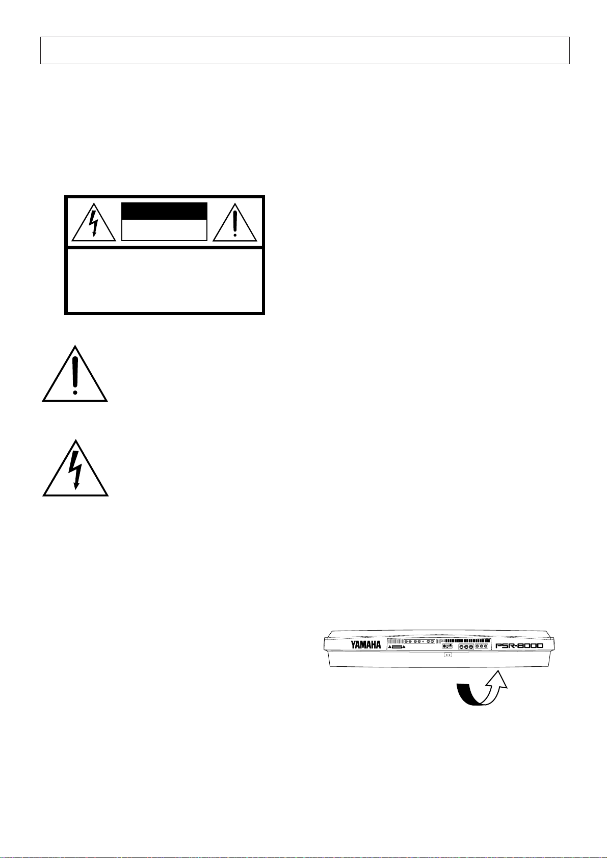
NAME PLATE LOCATION: The graphic below indicates the location of the name plate. The model number,
serial number, power requirements, etc., are located on
this plate. You should record the model number, serial
number, and the date of purchase in the spaces provided
below and retain this manual as a permanent record of
your purchase.
Model _____________________________________
92-469- ➀
Serial No. __________________________________
Purchase Date ______________________________
Page 3

IMPORTANT SAFETY INSTRUCTIONS
INFORMATION RELATING TO PERSONAL INJURY, ELECTRICAL SHOCK,
AND FIRE HAZARD POSSIBILITIES HAS BEEN INCLUDED IN THIS LIST.
WARNING- When using any electrical or electronic prod-
uct, basic precautions should always be followed. These precautions include, but are not limited to, the following:
1. Read all Safety Instructions, Installation Instructions,
Special Message Section items, and any Assembly Instructions
found in this manual BEFORE making any connections, including connection to the main supply.
2. Main Power Supply Verification: Yamaha products are
manufactured specifically for the supply voltage in the area
where they are to be sold. If you should move, or if any doubt
exists about the supply voltage in your area, please contact
your dealer for supply voltage verification and (if applicable)
instructions. The required supply voltage is printed on the
name plate. For name plate location, please refer to the graphic
found in the Special Message Section of this manual.
3. This product may be equipped with a polarized plug
(one blade wider than the other). If you are unable to insert the
plug into the outlet, turn the plug over and try again. If the
problem persists, contact an electrician to have the obsolete
outlet replaced. Do NOT defeat the safety purpose of the plug.
4. Some electronic products utilize external power sup-
plies or adapters. Do NOT connect this type of product to any
power supply or adapter other than one described in the owners
manual, on the name plate, or specifically recommended by
Yamaha.
5. WARNING: Do not place this product or any other
objects on the power cord or place it in a position where anyone could walk on, trip over, or roll anything over power or
connecting cords of any kind. The use of an extension cord is
not recommended! If you must use an extension cord, the
minimum wire size for a 25' cord (or less) is 18 AWG. NOTE:
The smaller the AWG number, the larger the current handling
capacity. For longer extension cords, consult a local electrician.
6. Ventilation: Electronic products, unless specifically
designed for enclosed installations, should be placed in locations that do not interfere with proper ventilation. If instructions for enclosed installations are not provided, it must be
assumed that unobstructed ventilation is required.
7. Temperature considerations: Electronic products
should be installed in locations that do not significantly contribute to their operating temperature. Placement of this product close to heat sources such as; radiators, heat registers and
other devices that produce heat should be avoided.
8. This product was NOT designed for use in wet/damp loca-
tions and should not be used near water or exposed to rain. Examples of wet/damp locations are; near a swimming pool, spa, tub,
sink, or wet basement.
9. This product should be used only with the components
supplied or; a cart, rack, or stand that is recommended by the
manufacturer. If a cart, rack, or stand is used, please observe all
safety markings and instructions that accompany the accessory
product.
10. The power supply cord (plug) should be disconnected from
the outlet when electronic products are to be left unused for extended periods of time. Cords should also be disconnected when
there is a high probability of lightening and/or electrical storm
activity.
11. Care should be taken that objects do not fall and liquids are
not spilled into the enclosure through any openings that may exist.
12. Electrical/electronic products should be serviced by a
qualified service person when:
a. The power supply cord has been damaged; or
b. Objects have fallen, been inserted, or liquids have been
spilled into the enclosure through openings; or
c. The product has been exposed to rain: or
d. The product dose not operate, exhibits a marked change
in performance; or
e. The product has been dropped, or the enclosure of the
product has been damaged.
13. Do not attempt to service this product beyond that de-
scribed in the user-maintenance instructions. All other servicing
should be referred to qualified service personnel.
14. This product, either alone or in combination with an ampli-
fier and headphones or speaker/s, may be capable of producing
sound levels that could cause permanent hearing loss. DO NOT
operate for a long period of time at a high volume level or at a
level that is uncomfortable. If you experience any hearing loss or
ringing in the ears, you should consult an audiologist.
IMPORTANT: The louder the sound, the shorter the time period
before damage occurs.
15. Some Yamaha products may have benches and/or acces-
sory mounting fixtures that are either supplied as a part of the
product or as optional accessories. Some of these items are designed to be dealer assembled or installed. Please make sure that
benches are stable and any optional fixtures (where applicable) are
well secured BEFORE using. Benches supplied by Yamaha are
designed for seating only. No other uses are recommended.
PLEASE KEEP THIS MANUAL
92-469-2
Page 4
PRECAUTIONS
PLEASE READ CAREFULLY BEFORE PROCEEDING
* Please keep these precautions in a safe place for future reference.
WARNING
Always follow the basic precautions listed below to avoid the possibility of serious injury or even death from electrical shock,
short-circuiting, damages, fire or other hazards. These precautions include, but are not limited to, the following:
• Do not open the instrument or attempt to disassemble the internal parts
or modify them in any way. The instrument contains no user-serviceable
parts. If it should appear to be malfunctioning, discontinue use immediately and have it inspected by qualified Yamaha service personnel.
• Do not expose the instrument to rain, use it near water or in damp or wet
conditions, or place containers on it containing liquids which might spill
into any openings.
• If the power cord or plug becomes frayed or damaged, or if there is a
sudden loss of sound during use of the instrument, or if any unusual smells
CAUTION
Always follow the basic precautions listed below to avoid the possibility of physical injury to you or others, or damage to the
instrument or other property. These precautions include, but are not limited to, the following:
• Do not place the power cord near heat sources such as heaters or radiators, and do not excessively bend or otherwise damage the cord, place
heavy objects on it, or place it in a position where anyone could walk on,
trip over, or roll anything over it.
• When removing the electric plug from the instrument or an outlet, always
hold the plug itself and not the cord. Pulling by the cord can damage it.
• Do not connect the instrument to an electrical outlet using a multipleconnector. Doing so can result in lower sound quality, or possibly cause
overheating in the outlet.
• Remove the electric plug from the outlet when the instrument is not to be
used for a long time, or during electrical storms.
• Before connecting the instrument to other electronic components, turn off
the power for all components. Before turning the power on or off for all
components, set all volume levels to minimum.
• Do not expose the instrument to excessive dust or vibrations, or extreme
cold or heat (such as in direct sunlight, near a heater, or in a car during the
day) to prevent the possibility of panel disfiguration or damage to the
internal components.
• Do not use the instrument near other electrical products such as televisions, radios, or speakers, since this might cause interference which can
affect proper operation of the other products.
• Do not place the instrument in an unstable position where it might accidentally fall over.
• Before moving the instrument, remove all connected cables.
• When cleaning the instrument, use a soft, dry cloth. Do not use paint
thinners, solvents, cleaning fluids, or chemical-impregnated wiping cloths.
Also, do not place vinyl or plastic objects on the instrument, since this
might discolor the panel or keyboard.
• Do not rest your weight on, or place heavy objects on the instrument, and
do not use excessive force on the buttons, switches or connectors.
• Use only the stand specified for the instrument. When attaching the stand
or rack, use the provided screws only. Failure to do so could cause damage to the internal components or result in the instrument falling over.
• Do not place objects in front of the instrument’s air vents on the top and
rear panels, since this may prevent adequate ventilation of the internal
components, and possibly result in the instrument overheating.
Also, be careful to place the instrument on a flat, level surface to prevent
blockage of the air vents on the bottom panel.
• Do not operate the instrument for a long period of time at a high or uncomfortable volume level, since this can cause permanent hearing loss. If you
experience any hearing loss or ringing in the ears, consult a physician.
■REPLACING THE BACKUP BATTERY
The PSR-8000 requires four 1.5 V C size (LR14) batteries for memory backup
power. If no backup batteries are installed, the memory contents will be lost
when the instrument is unplugged from the AC mains supply. Please use
4
(1)
or smoke should appear to be caused by it, immediately turn off the power
switch, disconnect the electric plug from the outlet, and have the instrument inspected by qualified Yamaha service personnel.
• Only use the voltage specified as correct for the instrument. The required
voltage is printed on the name plate of the instrument.
• Before cleaning the instrument, always remove the electric plug from the
outlet. Never insert or remove an electric plug with wet hands.
• Check the electric plug periodically and remove any dirt or dust which
may have accumulated on it.
alkaline batteries.
1.Before changing the battery be sure to save any important data to disk
by using the SAVE TO DISK function described on page 141.
2.Turn the PSR-8000 power OFF and unplug the power cord from both the
AC wall socket and the instrument’s rear panel. Turn the instrument upside down and rest it on a blanket or other soft surface.
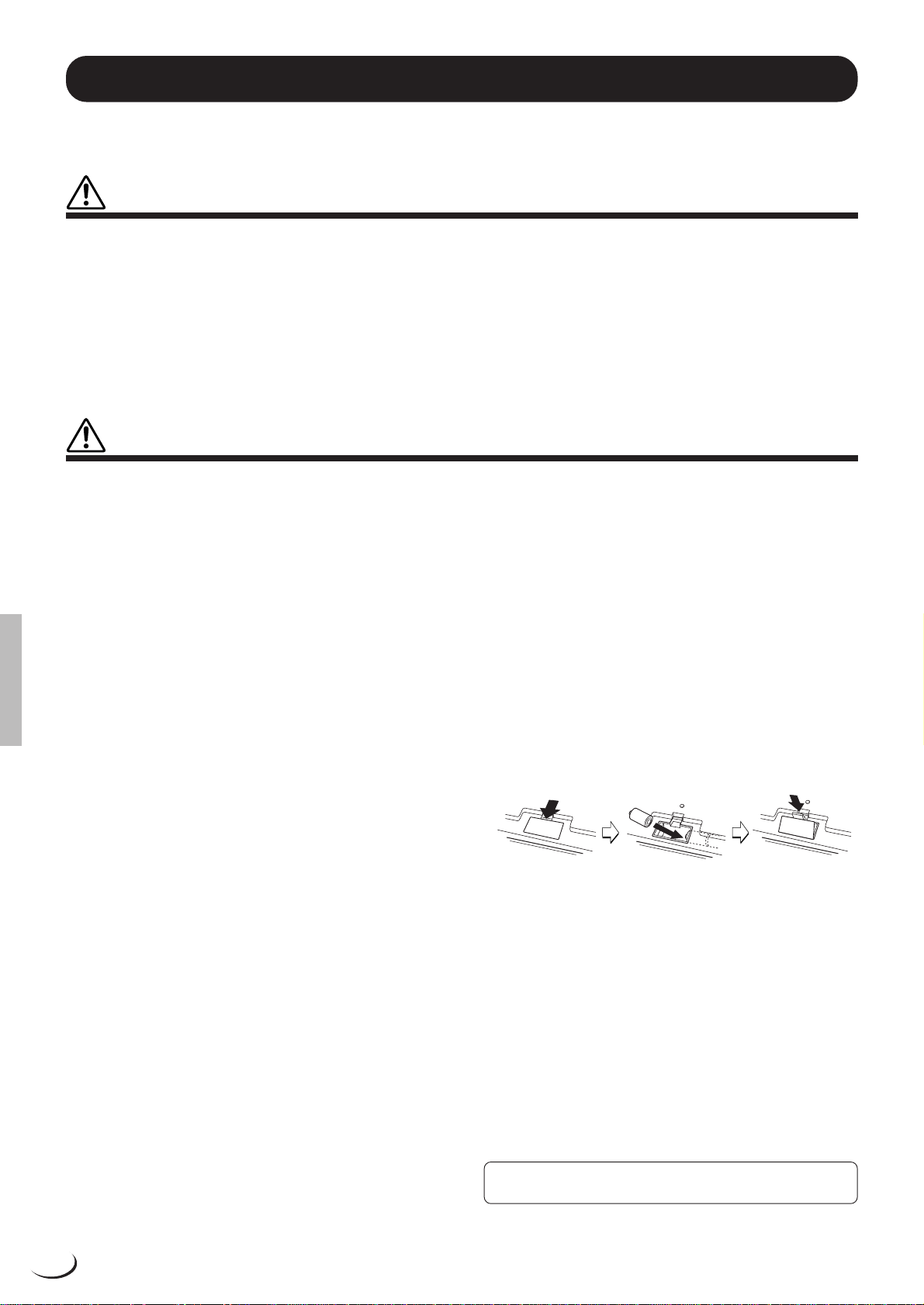
3.Open Battery Compartment Cover
Open the battery compartment cover — located on the instrument’s
bottom panel — by pressing on the two latches on the cover and pulling
outward, as shown in the illustration.
4.Remove the old batteries (if installed).
Remove the old batteries and wait at least one minute to ensure that all
data is fully cleared.
5.Insert Batteries
Insert the four batteries, being careful to follow the polarity markings on
the bottom panel.
6.Replace Cover
Replace the compartment cover, making sure that it locks firmly in place.
• Always make sure all batteries are inserted in conformity with the +/– polarity markings. Failure to do so might result in overheating, fire, or battery fluid
leakage.
• Always replace all batteries at the same time. Do not use new batteries
together with old ones. Also, do not mix battery types, such as alkaline
batteries with manganese batteries, or batteries from different makers, or
different types of batteries from the same maker, since this can cause
overheating, fire, or battery fluid leakage.
• Do not dispose of batteries in fire.
• Do not attempt to recharge batteries that are not intended to be charged.
• If the instrument is not to be in use for a long time, remove the batteries
from it (after saving any important data to disk), in order to prevent possible fluid leakage from the battery.
• Keep batteries away from children.
■SAVING USER DATA
• Always save data to a floppy disk frequently, in order to help prevent the
loss of important data due to a malfunction or user operating error.
Yamaha cannot be held responsible for damage caused by improper use or modifications to the instrument, or data that is lost or destroyed.
Always turn the power off when the instrument is not in use.
Make sure to discard used batteries according to local regulations.
Page 5
Handling the Floppy Disk Drive(FDD) and Floppy Disk
Precautions
• Be sure to handle floppy disks and treat the disk drive with care. Follow
the important precautions below.
Compatible Disk Type
• 3.5” 2DD and 2HD type floppy disks can be used.
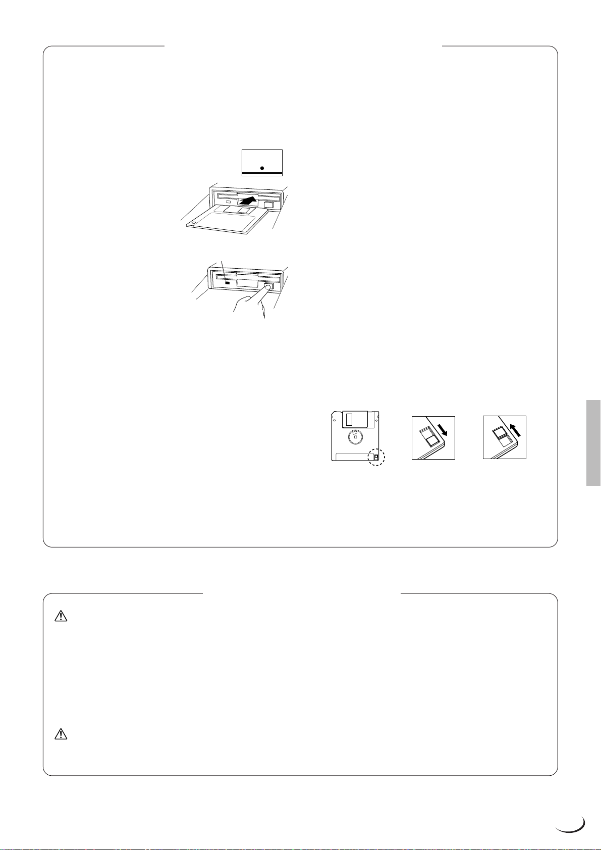
■ Inserting/Ejecting Floppy Disks
DISK IN USE
To insert a floppy disk into the disk drive:
• Hold the disk so that the label of the
disk is facing upward and the sliding
shutter is facing forward, towards
the disk slot. Carefully insert the disk
into the slot, slowly pushing it all the
way in until it clicks into place and
the eject button pops out.
To eject a floppy disk:
• Before ejecting a floppy disk make
sure that the floppy disk drive is not
in operation (the DISK IN USE indicator should be off, except when the
internal hard disk is being accessed).
Press the eject button slowly as far as it will go; the disk will automatically pop out. When the disk is fully ejected, carefully remove it by hand.
• Never attempt to remove the disk or turn the power off during recording,
reading and playing back. Doing so can damage the disk and possibly
the disk drive.
• If the eject button is pressed too quickly, or if it is not pressed in as far as
it will go, the disk may not eject properly. The eject button may become
stuck in a half-pressed position with the disk extending from the drive
slot by only a few millimeters. If this happens, do not attempt to pull out
the partially ejected disk, since using force in this situation can damage
the disk drive mechanism or the floppy disk. To remove a partially ejected
disk, try pressing the eject button once again, or push the disk back into
the slot and then repeat the eject procedure.
• Be sure to remove the floppy disk from the disk drive before turning off
the power. A floppy disk left in the drive for extended periods can easily
pick up dust and dirt that can cause data read and write errors.
This lamp is always on
while the power is on.
Cleaning the Disk Drive Read/Write Head
• Clean the read/write head regularly. This instrument employs a precision magnetic read/write head which, after an extended period of use,
will pick up a layer of magnetic particles from the disks used that will
eventually cause read and write errors.
• To maintain the disk drive in optimum working order Yamaha recommends that you use a commercially-available dry-type head cleaning
disk to clean the head about once a month. Ask your Yamaha dealer
about the availability of proper head-cleaning disks.
Never insert anything but floppy disks into the disk drive. Other objects
may cause damage to the disk drive or floppy disks.
■ About the Floppy Disks
To handle floppy disks with care:
• Do not place heavy objects on a disk or bend or apply pressure to the
disk in any way. Always keep floppy disks in their protective cases
when they are not in use.
• Do not expose the disk to direct sunlight, extremely high or low temperatures, or excessive humidity, dust or liquids.
• Do not open the sliding shutter and touch the exposed surface of the
floppy disk inside.
• Do not expose the disk to magnetic fields, such as those produced by
televisions, speakers, motors, etc., since magnetic fields can partially or
completely erase data on the disk, rendering it unreadable.
• Never use a floppy disk with a deformed shutter or housing.
• Do not attach anything other than the provided labels to a floppy disk.
Also make sure that labels are attached in the proper location.
To protect your data (Write-protect Tab):
• To prevent accidental erasure of important data, slide the disk’s writeprotect tab to the “protect” position (tab open).
Write protected Write enabled
Data backup
• For maximum data security Yamaha recommends that you keep two
copies of important data on separate floppy disks. This gives you a backup
if one disk is lost or damaged. To make a backup disk use the COPY
FILE/FD function on page 143.
Handling and Installation of Options
WARNING
• Before beginning installation, switch off the power to the PSR-8000 and
connected peripherals, and unplug them from the power outlet. Then
remove all cables connecting the PSR-8000 to other devices. (Leaving
the power cord connected while working can result in electric shock.
Leaving other cables connected can interfere with work.)
• Do not disassemble, modify, or apply excessive force to board areas and
connectors on hard disk, and SIMMs. Bending or tampering with boards
and connectors may lead to electric shock, fire, or equipment failures.
CAUTION
• Before handling the internal hard disk or SIMMs, you should briefly touch
the metal surface to which the hard-disk or SIMM cover is attached (or
* If SIMM memory, or hard disk fails to work properly, consult the item’s dealer or manufacturer for advice.
* Yamaha will not be held responsible for any damage or injury resuting from improper installation.
YAMAHA is not responsible for damage caused by improper handling or operation.
YAMAHA provides no guarantee against disk damage.
other such metallic area — be careful of any sharp edges) with your
bare hand so as to drain off any static charge from your body. Note that
even a slight amount of electrostatic discharge may cause damage to
these components.
• It is recommended that you wear gloves to protect your hands from
metallic projections on the PSR-8000 hard disk, SMMs, and other components. Touching leads or connectors with bare hands may cause finger cuts, and may also result in poor electrical contact or electrostatic
damage.
• Take care to avoid dropping screws into the PSR-8000 unit. If a screw
does fall in, be sure to remove it before replacing the cover and powering
up the unit. Starting the unit with a loose screw inside may lead to improper operation or equipment failure. (If you are unable to retrieve a
dropped screw, consult your Yamaha dealer for advice.)
5
Page 6
Congratulations!
You are the proud owner of an extraordinary electronic keyboard. The Yamaha PSR-8000
PortaTone combines the most advanced tone generation technology with state-of-the-art digital
electronics and features to give you stunning sound quality with maximum musical versatility. The
advanced Auto Accompaniment, Vocal Harmony, and Sampler features, in particular, are brilliant
examples of how Yamaha technology can significantly expand your musical horizons. A large-size
graphic display and easy-to-use interface also greatly enhance the operability of this advanced
instrument.
In order to make the most of your PortaTone’ s features and vast performance potential, we urge
you to read the manuals thor oughly while trying out the various features described. Keep the manuals
in a safe place for later reference.
Packing List
Your PSR-8000 includes the following items:
• PSR-8000 PortaTone x 1
• AC Power Cord x 1
• AC Plug Adaptor x 1 (in applicable areas only)
• Music Stand x 1
• Audio CD x 1 (includes sound sources for sampling: page 88)
• Floppy Disk x 1 (includes accompaniment style files: page 28)
• Owner’s Manual
• The illustrations and LCD screens as shown in this owner’s manual are for instructional purposes only, and may
appear somewhat different from those on y our instrument.
• Unauthorized copying of copyrighted software for purposes other than the purchaser’s personal use is prohibited.
• The Vocal Harmony feature included in this product is manufactured under license from IVL Technologies Ltd.,
U.S. Patent numbers 5231671, 5301259, and 5428708.
● Trademarks:
• Apple and Macintosh are trademarks of Apple Computer, Inc.
• IBM-PC/AT is a trademark of International Business MachinesCorporation.
• Windows is the registered trademark of Microsoft
• All other trademarks are the property of their respective holders.
®
Corporation.
The Panel Logos
The logos printed on the PSR-8000 panel indicate standards/formats it supports and special features it includes.
GM System Level 1
“GM System Level 1” is an addition to the MIDI standard which
guarantees that any data conforming to the standard will play
accurately on any GM-compatible tone generator or synthesizer from any manufacturer.
XG
XG is a new Yamaha MIDI specification which significantly
expands and improves on the “GM System Level 1” standard
with greater voice handling capacity, expressive control, and
effect capability while retaining full compatibility with GM. By
using the PSR-8000’s XG voices, it is possible to record XGcompatible song files.
The Yamaha XF format enhances the SMF (Standard MIDI
File) strandard with greater functionality and open-ended
expandability for the future. The PSR-8000 is capable of
displaying lyrics when an XF file containing lyric data is
played.
• SMF (Standard MIDI File) is the most common format used for
MIDI sequence files. The PSR-8000 is compatible with SMF
Formats 0 and 1, and records “song” data using SMF Format
0.
XF
6
Page 7
,,,,,,,,,,,,,,,,,
,
Q
¢
QQQQQQQQQQQQQQQQQ
¢¢¢¢¢¢¢¢¢¢¢¢¢¢¢¢¢
Main Features
Main Features
The PSR-8000 is a sophisticated electronic keyboard which offers a comprehensive range of
features for extensive musical versatility and expressive control: a touch-sensitive 61-key
keyboard, an outstanding range of voices (including XG voices), top quality auto-accompaniment with an extensive range of styles, song recording and playback capability, registration
memory, and a built-in floppy disk for convenient data storage and retrieval, and more.
The following features, in particular, give the PSR-8000 extraordinary musical production
and performance power.
● High-quality sampling capability — with expandable
wave memory — lets you sample and edit sounds
via microphone or from line sources, and then use
the sampled waveforms in original voices.
● Unique Vocal Harmony feature incorporates advanced voice-processing technology to automatically produce vocal harmony based on a lead vocal,
making a single singer sound like a vocal group.
● An advanced effect system incorporating 8 separate DSPs (Digital Signal Processors) and 5-band
master equalization adds depth, ambience, and
animation to your sound.
● Comprehensive Mixing Console displays provide
professional sound control and production capability.
● Large multi-function LCD display panel with displaybased buttons and dials, plus comprehensive display prompts and messages, makes operation easy
and intuitive.
● Create original voices using the Voice Creator feature for a totally original sound.
● Style Creator feature lets you create “groove style”
variations on existing styles, or create entirely new
styles that are a perfect match for your performing
requirements.
● One Touch Setting feature automatically selects
appropriate voice, effect, and other settings for the
selected accompaniment style — all you have to do
is select a style, press the ONE TOUCH SETTING
button and play.
● Multi Pads record and play short rhythmic and melodic sequences that can be used to add impact
and variety to your performances.
● Voice/Style List Customize feature lets you rearrange the list contents for fast, efficient access in
performance situations.
● Unique “Talk” function instantly makes the settings
you need for mid-performance announcements and
interludes.
● Loop Send and Return jacks allow extra system
flexibility: connect external signal-processing equipment for enhanced effect capability, or feed a mixer
for improved sound and on-stage monitoring quality.
● Optional internal hard disk provides high-volume,
high-speed data storage and retrieval.
● A selection of MIDI Templates eliminates tedious
setup procedures by providing instantly selectable
MIDI setups for a range of situations.
● To Host interface plus a range of MIDI functions for
expanded musical performance (General MIDI System Level 1 and Yamaha XG/XF compatible).
DOC
The DOC voice allocation format provides data playback
compatibility with a wide range of Yamaha instruments and
MIDI devices, including the Clavinova series.
Style File Format
The Style File Format — SFF — is Yamaha’s original style file
format which uses a unique conversion system to provide
high-quality automatic accompaniment based on a wide range
of chord types. The PSR-8000 uses the SFF internally, reads
optional SFF style disks, and creates SFF styles using the
STYLE CREATOR feature.
Vocal Harmony
Vocal Harmony employs state-of-the-art digital signal processing technology to automatically add appropriate vocal
harmony to a lead vocal line sung by the user. Vocal Harmony
can even change the character and gender of the lead voice
as well as the added voices to produce a wide range of vocal
harmony effects.
7
Page 8
,,,,,,,,,,,,,,,,
,
Q
¢
QQQQQQQQQQQQQQQQ
¢¢¢¢¢¢¢¢¢¢¢¢¢¢¢¢
Contents
Contents
Panel Controls 10
Connections & Music Stand 12
The Demonstration 17
The PSR-8000 Display &
Display-based Controls 19
■ The MIXING CONSOLE Buttons .... 19
■ The [EXIT] Button............................ 20
■ The [DIRECT ACCESS] Button ...... 20
■ The [LCD CONTRAST] Control ...... 20
■ The 5-language Help Function ........20
■ Display Messages ........................... 21
■ Name Entry .....................................21
Playing the PSR-8000 22
■ Before You Begin ............................ 22
The PSR-8000 Parts & Voices......... 22
■ Part Poly/Mono Modes & Mono
Note Priority ....................................22
■ The XG Voices ................................ 23
■ The Organ Flute Voice .................... 23
■ Keyboard Percussion and Special
Effects ............................................. 24
Procedure:
Part Selection and Voice
Assignment
..........................................24
Voice Effects........................................ 26
Other Play Mode Functions............. 26
■ Master Transpose ...........................26
■ Octave Change ...............................27
■ Left Hold ..........................................27
■ Pitch Bend & Modulation Wheels ....27
Using the Accompaniment
Section 28
Procedure:
Auto Accompaniment......... 28
■ Auto Accompaniment Fingering
Modes .............................................30
■ Auto Accompaniment Start Modes.. 33
■ The MAIN A and MAIN B Sections
and Fill-ins....................................... 34
■ Tempo Control ................................ 35
■ Fade-ins and Fade-outs .................. 35
■ Synchronized Stop .......................... 35
■ Accompaniment Volume .................36
■ Accompaniment Part Switching ...... 36
■ Virtual Arranger ............................... 36
■ Harmony/Echo ................................ 37
■ One Touch Setting ..........................38
The Mixing Console 39
Mixing Console Parameters ............ 39
VOLUME/PAN/EQ.............................. 40
■ VOLUME ......................................... 40
■ PANPOT ......................................... 40
■ EQ LOW ..........................................40
■ EQ HIGH ......................................... 40
■ HPF1 ............................................... 40
■ HPF2 ............................................... 40
FILTER ...............................................41
■ HARMONIC CONTENT ..................41
■ BRIGHTNESS .................................41
EFFECT DEPTH................................. 41
■ REVERB (DSP1)............................. 41
■ CHORUS (DSP2) ............................41
■ DSP3............................................... 42
■ DSP4-7............................................ 42
EFFECT TYPE.................................... 42
■ Type Page....................................... 42
● EFFECT BLOCK & TYPE ...........42
● TYPE LIST ..................................42
■ Parameter Page .............................. 42
● BLOCK ........................................ 42
● TYPE ........................................... 42
● PARAMETER .............................. 43
● VALUE ........................................ 43
● LEVEL ......................................... 43
● USER SET ..................................43
TUNING .............................................. 44
■ TRANSPOSE .................................. 44
■ TUNING .......................................... 44
■ OCTAVE ......................................... 44
■ PITCH BEND RANGE..................... 44
■ PORTAMENTO TIME .....................44
MASTER EQ....................................... 45
■ EQ1 … EQ5 ....................................45
■ Q & FREQ ....................................... 45
■ TOTAL GAIN ADJUST.................... 45
■ STORE............................................ 45
Registration Memory 46
Registering the Panel Settings....... 46
Recalling the Registered Panel
Settings
.................................................47
The Freeze Function.......................... 47
Organ Flute Voice Editing 48
■ ORGAN TYPE................................. 48
■ ROTARY SP SPEED ......................48
■ VIBRATO ON/OFF .......................... 48
■ VIBRATO DEPTH ...........................48
■ FOOTAGE....................................... 48
■ VOLUME & ATTACK ...................... 49
■ EFFECT & EQ SETTINGS.............. 49
Custom Voice Creator 51
Procedure:
Engaging the Easy/
Full Edit Mode
The Easy Edit Parameters ...............52
EDIT .................................................... 52
■ FILTER............................................ 52
■ EG ................................................... 52
■ VIBRATO ........................................ 53
■ VOLUME ......................................... 53
STORE/CLEAR ..................................53
■ NAME.............................................. 53
■ STORE............................................ 53
■ CLEAR CUSTOM VOICE ............... 54
The Full Edit Parameters.................. 54
■ ELEMENT SELECTION
(not available for the Drum Kits) .................. 54
VOICE ................................................. 55
■ MASTER VOLUME ......................... 55
■ INITIAL TOUCH CURVE................. 55
■ SCALE CURVE............................... 55
■ MODULATION ................................55
■ AFTER TOUCH............................... 55
..................................... 51
E1:WAVEFORM ................................. 56
■ WAVEFORM
(INSTRUMENT for the Drum Kits) ................ 56
■ COARSE TUNE/FINE TUNE ..........56
■ VOLUME ......................................... 56
■ KEY ON DELAY.............................. 56
■ PAN ................................................. 56
■ NOTE LIMIT
(not available for the Drum Kits) .................. 56
■ VELOCITY LIMIT
(not available for the Drum Kits) .................. 56
E2:EG ................................................. 57
■ AMP RATE
(Amplitude Envelope Rate) ............. 57
■ AMP LEVEL
(Amplitude Envelope Level) ............ 57
■ PITCH RATE (Pitch Envelope Rate)58
■ PITCH LEVEL .................................58
■ FILTER RATE .................................58
■ FILTER LEVEL................................ 58
E3:FILTER .......................................... 59
■ FILTER1 & FILTER2 ....................... 59
■ RESONANCE ................................. 59
■ TOUCH TO FILTER ........................ 59
E4:LFO ............................................... 59
■ LFO (Low Frequency Oscillator) .....59
■ DELAY (Delay Vibrato) ................... 60
VOICE SET ......................................... 60
■ REVERB, CHORUS, and DSP
DEPTH ............................................ 60
■ DSP TYPE and VARIATION ........... 60
■ EQ LOW and HIGH .........................60
STORE/CLEAR ..................................61
■ NAME.............................................. 61
■ STORE............................................ 61
■ CLEAR CUSTOM VOICE ............... 61
The Custom Style Creator 62
Procedure:
Custom Style Recording.... 62
CUSTOM STYLE CREATOR Param-
eters .......................................................66
■ Exiting ............................................. 66
BASIC ................................................. 66
■ SECTION/PATTERN LENGTH/
BEAT/TEMPO ................................. 66
■ PART COPY ................................... 67
SETUP ................................................ 67
■ VOICE ............................................. 67
■ SETUP COPY ................................. 68
EDIT .................................................... 68
■ QUANTIZE ...................................... 68
■ VELOCITY CHANGE ...................... 69
■ MEASURE COPY ...........................69
■ MEASURE CLEAR ......................... 69
■ REMOVE CONTROL EVENT ......... 69
■ REMOVE DUPLICATE NOTES ...... 70
STORE/CLEAR ..................................70
■ NAME.............................................. 70
■ STORE............................................ 70
■ CLEAR CUSTOM STYLE ...............70
PARAMETER EDIT ............................ 71
■ PART/SOURCE ROOT/SOURCE
CHORD ........................................... 71
■ NTR/NTT ......................................... 71
■ HIGH KEY/NOTE LIMIT.................. 72
■ RTR ................................................. 72
8
Page 9
Contents
Custom Style Recording via an
External Sequence Recorder
■ Connections ....................................73
■ Creating the Data ............................ 73
■ Saving and Loading the Sequence
Data.................................................75
■ Refining the Style ............................ 75
.......... 73
The Groove Style Creator 76
Procedure:
Creating a Groove Style..... 76
GROOVE STYLE CREATOR
Parameters
■ Exiting ............................................. 77
SETUP ................................................ 78
■ PART ON/OFF/TEMPO ..................78
■ VOICE ............................................. 78
■ SETUP COPY ................................. 78
GROOVE ............................................79
■ GROOVE ........................................ 79
■ SETUP COPY ................................. 79
DYNAMICS ......................................... 80
■ DYNAMICS .....................................80
■ SETUP COPY ................................. 80
STORE/CLEAR ..................................80
■ NAME ..............................................80
■ STORE ............................................81
■ GROOVE STYLE CLEAR ............... 81
■ STORE AS CUSTOM STYLE ......... 81
■ CUSTOM STYLE CLEAR ...............81
DRUM EXCHANGE ............................ 82
■ DRUM EXCHANGE ........................82
■ SETUP COPY ................................. 82
...........................................77
Vocal Harmony 83
Using Vocal Harmony....................... 83
■ Setting Up ....................................... 83
■ The VOCAL/SAMPLING Buttons .... 83
■ Selecting a VOCAL HARMONY
Type ................................................ 84
■ Producing the VOCAL HARMONY
Effect ...............................................84
Editing the Vocal Harmony
Parameters ........................................84
■ The Vocal Harmony Modes............. 85
Sampling 88
PSR-8000 Waves & Waveforms ....... 88
Setting Up for Sampling ................... 89
■ Connecting the Source.................... 89
■ Setting Levels.................................. 89
Sampling & File Import..................... 90
■ Sampling New Material ...................90
■ NAME/CLEAR................................. 92
Wave Edit ........................................... 93
■ EDIT ................................................ 93
■ NAME/CLEAR/DISK ....................... 96
Waveform Edit................................... 97
■ EDIT ................................................ 97
■ NAME/CLEAR/DISK ....................... 98
■ STORE AS CUSTOM VOICE .........99
Song Playback 100
Procedure:
Song Playback....................100
Enter Next Song .............................. 101
Pause, Fast Forward & Reverse .... 102
Lyric Display....................................102
The CHORD DETECT and VOCAL
HARM. Parameters.......................... 102
■ CHORD DETECT.......................... 102
■ VOCAL HARM. ............................. 102
Setting the Song Playback Order .. 103
MIXING CONSOLE Operation During
Song Playback ................................103
■ FADER .......................................... 103
■ FULL ............................................. 104
Song Recording 105
Procedure:
Song Recording .................105
Procedure:
Quick Record ......................106
■ THE TRACK INDICATORS........... 108
■ TRACK DELETE ........................... 108
■ PLAYBACK ...................................108
■ EXITING ........................................108
Procedure:
Chord Step Recording...... 109
■ DELETING EVENTS .....................110
■ INSERTING OR DELETING
MEASURES .................................. 110
■ SAVING THE CHORD STEP
DATA.............................................110
Quick Record Mode Edit Functions111
■ RENAME SONG ...........................111
■ SONG DELETE............................. 111
Procedure:
Multi Track Record ............ 111
■ THE TRACK INDICATORS........... 113
■ TRACK DELETE ........................... 114
■ PLAYBACK ...................................114
■ EXITING ........................................114
Procedure:
Punch-In & Replace
Recording
...........................................114
Multi Track Record Mode Edit
Functions ......................................... 116
■ RENAME SONG ...........................116
■ QUANTIZE .................................... 116
■ TRACK MIX................................... 117
■ NOTE SHIFT .................................117
■ SONG DELETE............................. 117
Multi Track Record Set Up ............. 118
■ VOICE ........................................... 118
■ OTHER SET UP PARAMETERS ..118
The Multi Pads 119
MULTI PAD Playback ...................... 119
Procedure:
MULTI PAD Recording ..... 119
■ MULTI PAD NAME........................ 121
■ MULTI PAD CLEAR ...................... 121
The Repeat & Chord Match Modes 121
■ REPEAT ........................................121
■ CHORD MATCH ...........................121
The PSR-8000 “Functions” 122
The FUNCTION Parameters........... 122
■ The [EXIT] Button.......................... 122
F1: MASTER TUNE/SCALE ............123
■ MASTER TUNE ............................ 123
■ SCALE (ARABIC).......................... 123
F2: SPLIT POINT/FINGERING ........123
■ SPLIT POINT ................................123
■ FINGERING ..................................124
F3: CONTROLLER........................... 124
■ FOOT CONTROLLER................... 124
■ PANEL CONTROLLER .................126
F4: REGISTRATION/ONE TOUCH
SETTING/VOICE SET ...................... 127
■ REGISTRATION ...........................127
■ ONE TOUCH SETTING ................ 127
■ VOICE SET ................................... 128
F5: HARMONY/ECHO...................... 129
F6: CUSTOMIZE LIST...................... 129
F7: TALK SETTING .........................130
F8: UTILITY ...................................... 131
F9: MIDI ............................................ 132
■ TEMPLATE ...................................132
■ SYSTEM ....................................... 134
■ TRANSMIT ....................................135
■ RECEIVE ...................................... 136
■ PANEL CONTROL ........................ 138
Disk Operations 139
The DISK Parameters ......................139
■ Exiting ........................................... 140
LOAD FROM DISK........................... 140
SAVE TO DISK................................. 141
COPY FILE/FD ................................. 143
■ Copying Files ................................ 143
■ Copying Floppy Disks ................... 144
CHANGE SONG ORDER................. 144
RENAME FILE/SONG ...................... 145
DELETE FILE/SONG .......................145
FORMAT FD ..................................... 146
EDIT DIRECTORY............................ 146
■ NEW DIR....................................... 146
■ RENAME .......................................146
■ DELETE ........................................146
FORMAT HARD DISK...................... 147
CHECK HARD DISK ........................ 147
Troubleshooting 148
Index 150
Installing Options.............................152
Optional SIMM Installation ............. 152
Optional Hard Disk Installation...... 156
Voice List ............................................159
Keyboard Drum Assignments ...... 166
Style List ............................................. 168
Direct Access Chart......................... 170
Parameter Chart................................171
Effect Signal Flow Chart ................ 176
MIDI Data Format.............................. 177
MIDI Implementation Chart............ 196
Audio Sampling Library CD
Contents..............................................200
Specifications.................................... 203
9
Page 10
,,,,,,,,,,,,,,,,
,
Q
¢
QQQQQQQQQQQQQQQQ
¢¢¢¢¢¢¢¢¢¢¢¢¢¢¢¢
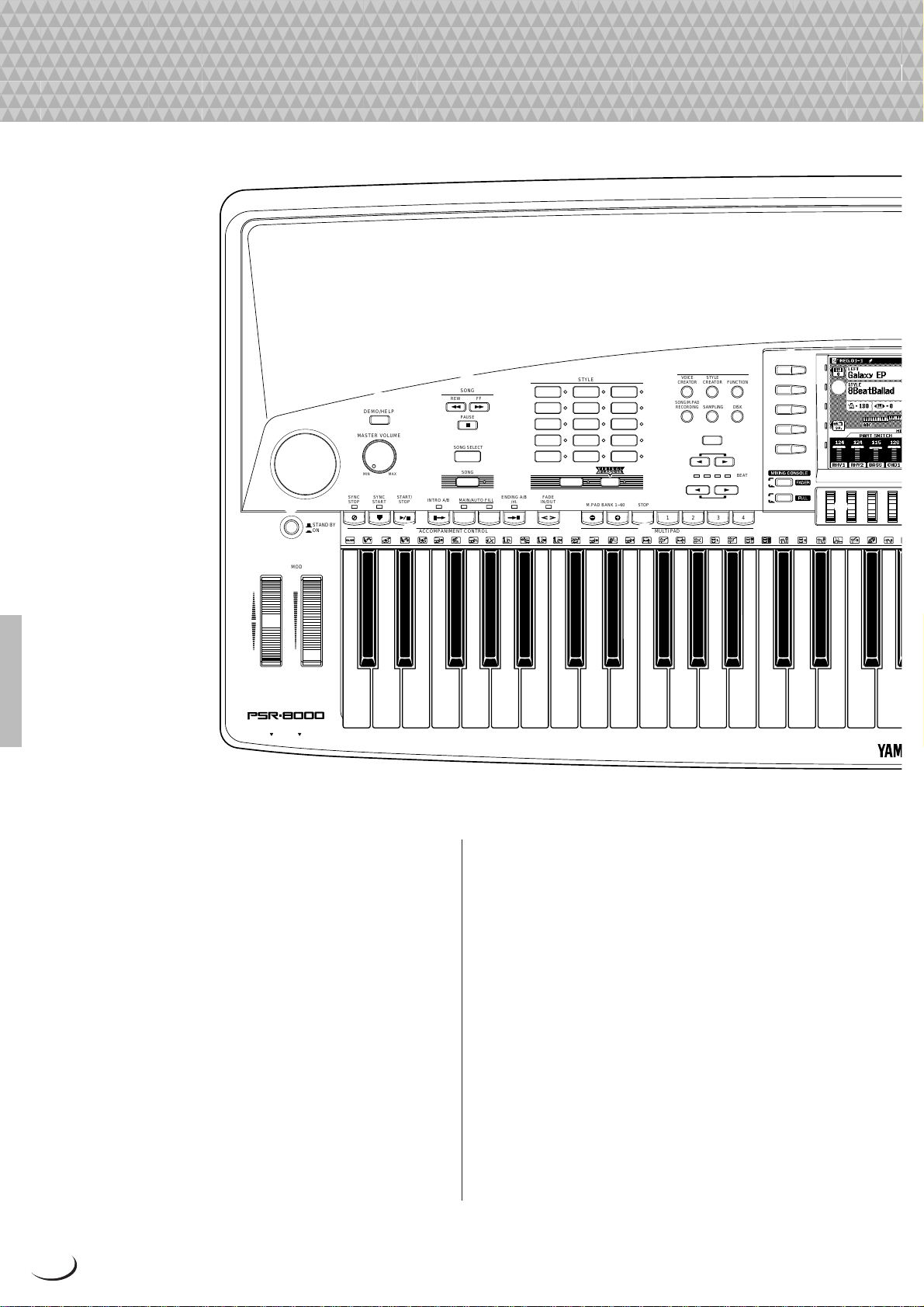
Panel Controls
Panel Controls
y u
PITCH BEND
UP
DOWN
1
MODULATION
MAX
MIN
MIC/LINE INPHONES
STAND BY
ON
DEMO/HELP
MASTER VOLUME
MIN MAX
SYNC
STOP
5
4
SONG
2
3
SYNC
START/
START
STOP
0 !
REW FF
PAUSE
SONG SELECT
SONG
A B
ENDING A/B
/rit.
INTRO A/B MAIN/AUTO FILL
ACCOMPANIMENT CONTROL MULTI PAD
8BEAT 1
8BEAT 2
16BEAT
BALLAD
ROCK
FADE
IN/OUT
DANCEFLOOR
COUNTRY
AUTO
ACCOMPANIMENT
STYLE
DISCO
SWING &
JAZZ
R & B
LATIN
BALLROOM
MARCH &
WALTZ
GROOVE
STYLE
CUSTOM
STYLE
M.PAD BANK 1~60 STOP
6
OVERALL/UTILITY
VOICE
CREATOR
CREATOR
SONG/M.PAD
RECORDING
SAMPLING DISK
7
8
9
12
STYLE
FUNCTION
DIRECT ACCESS
RESET
RESET
34
MASTER
TRANSPOSE
BEAT
TEMPO
#
A
B
C
D
E
@
$
PART
PART
%
1 STAND BY/ON Button.............................. page 17
2 DEMO/HELP Button .........................pages 17, 20
3 MASTER VOLUME Control...................... page 17
4 SONG Buttons ....................................... page 100
REW, FF, PAUSE, SONG SELECT, SONG
5 STYLE Buttons .................................pages 28, 36
8BEAT1, 8BEAT2, 16BEAT, BALLAD, ROCK,
DANCEFLOOR, DISCO, SWING & JAZZ, R & B,
COUNTRY, LATIN, BALLROOM, MARCH &
WALTZ, GROOVE STYLE, CUSTOM STYLE,
AUTO ACCOMPANIMENT, VIRTUAL ARRANGER
6 OVERALL/UTILITY Buttons
....................pages 51, 62, 88, 105, 119, 122, 139
VOICE CREATOR, STYLE CREATOR,
FUCTION, SONG/M.PAD RECORDING, SAMPLING, DISK
10
7 DIRECT ACCESS Button................pages 20, 170
8 MASTER TRANSPOSE <, > Buttons .... page 26
9 TEMPO <, > Buttons.............................. page 35
0 ACCOMPANIMENT CONTROL Buttons.. page 33
SYNCHRO STOP, SYNCHRO START, START/
STOP, INTRO A/B, MAIN/AUTO FILL A/B, ENDING A/B/rit., FADE IN/OUT
! MULTI PAD Buttons ............................... page 119
M.PAD BANK 1~60, STOP, 1—4
@ Liquid Crystal Display (LCD).................... page 19
# LCD (A—J) Buttons ................................. page 19
$ MIXING CONSOLE Buttons .................... page 19
FADER, FULL
Page 11
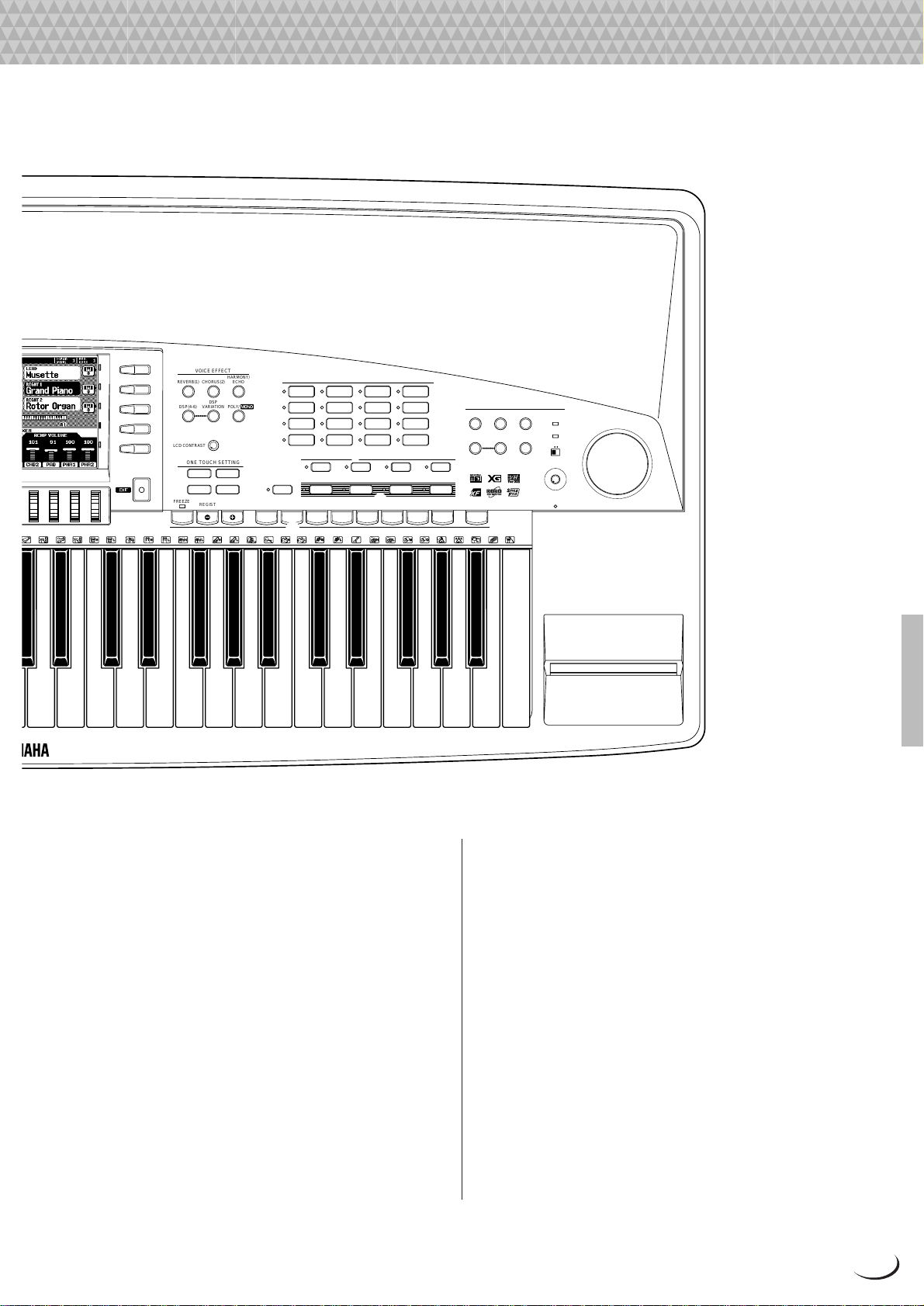
Panel Controls
^
F
G
H
I
J
VOICE EFFECT
REVERB(1) CHORUS(2)
DSP(4-6)
VARIATION
LCD CONTRAST
ONE TOUCH SETTING
FREEZE
REGIST BANK 1~16
&
DSP
*
21
43
HARMONY/
ECHO
POLY/
(
PIANO GUITAR
E.PIANO STRINGS
ACCORDION
LEFT HOLD
12
REGISTRATION MEMORY
e
)
VOICE
SAXOPHONE PERCUSSION
FLUTE XG
ORGAN
CHOIR&PAD
TRUMPETORGAN
BRASS
q
LEFT RIGHT 1 RIGHT 2 LEAD
LEFT RIGHT 1 RIGHT 2 LEAD
SYNTHESIZER
PART SELECT
PART ON/OFF
FLUTE
CUSTOM
VOICE
w
345678
VOCAL/SAMPLING
REVERB(1) CHORUS (2)
VOCAL
HARMONY
HARMONY(8)
VARIATION
MEMORY
r
DSP (7)
TALK
OVER
SIGNAL
MIC/LINE
INPUT VOLUME
MIN
DISK IN USE
MAX
t
% LCD dials ................................................. page 19
^ EXIT Button.............................................. page 20
& VOICE EFFECT Buttons.......................... page 26
REVERB (1), CHORUS (2), HARMONY/ECHO,
DSP (4—6), DSP VARIATION, POLY/MONO
* LCD CONTRAST Control ........................ page 20
( ONE TOUCH SETTING (1—4) Buttons... page 38
) VOICE Buttons......................................... page 25
PIANO, E.PIANO, ORGAN, ACCORDION, GUI-
TAR, STRINGS, TRUMPET, BRASS, SAXOPHONE, FLUTE, CHOIR&PAD, SYNTHESIZER,
PERCUSSION, XG, ORGAN FLUTE, CUSTOM
VOICE
q PART SELECT Buttons............................ page 22
LEFT, RIGHT 1, RIGHT 2, LEAD
w PART ON/OFF Buttons ............................ page 25
LEFT HOLD, LEFT, RIGHT 1, RIGHT 2, LEAD
e REGISTRATION MEMORY Buttons ........ page 46
FREEZE, REGIST BANK 1~16, 1—8, MEMORY
r VOCAL/SAMPLING Buttons & Controls
..........................................................pages 83, 88
REVERB(1), CHORUS(2), DSP(7), VOCAL
HARMONY(8), HARMONY VARIATION, TALK
OVER Indicator, SIGNAL Indicator, MIC/LINE
Switch, INPUT VOLUME Control
t Disk Drive............................................... page 139
y PITCH BEND Wheel ................................ page 27
u MODULA TION Wheel .............................. page 27
11
Page 12
,,,,,,,,,,,,,,,,
,
Q
¢
QQQQQQQQQQQQQQQQ
¢¢¢¢¢¢¢¢¢¢¢¢¢¢¢¢
Connections & Music Stand
Connections & Music Stand
CAUTION
RISK OF ELECTRIC SHOCK
DO NOT OPEN
RISQUE DE CHOC ÉLECTRIQUE–NE PAS OUVRIR.
AVIS :
LOOP SEND AUX IN/LOOP RETURN AUX OUT
R L/L+R R L/L+R
3 2 1
WARNING :
TO REDUCE THE RISK OF FIRE OR ELECTRIC SHOCK,
DO NOT EXPOSE THIS PRODUCT TO RAIN OR MOISTURE.
MIN MAX
TRIM
L/L+RR
TO HOST MIDI FOOT PEDAL
AC INLET
7 4 5
IN OUT THRU SWITCH 1 SWITCH 2 VOLUMEPC-1PC-2
MIDIMac
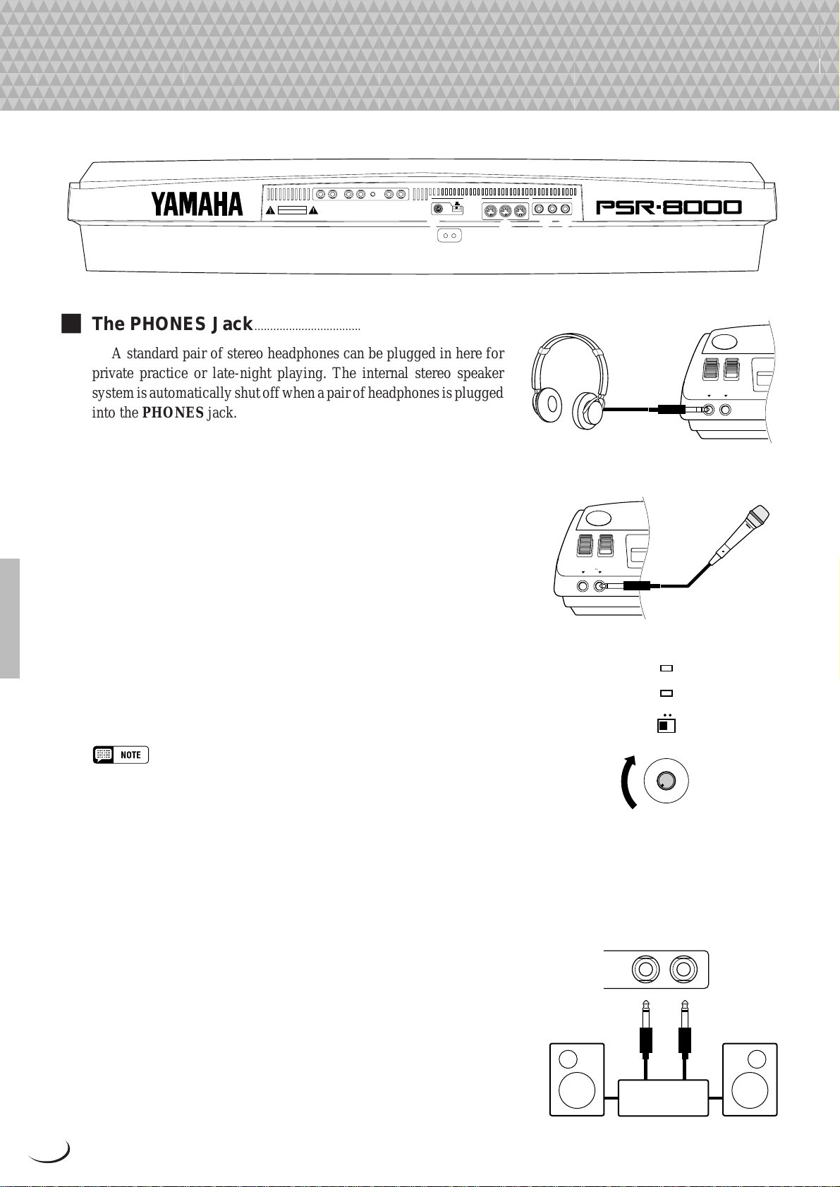
■ The PHONES Jack...............................................................................
A standard pair of stereo headphones can be plugged in here for
private practice or late-night playing. The internal stereo speaker
system is automatically shut off when a pair of headphones is plugged
into the PHONES jack.
■ The MIC/LINE IN Jack ......................................................................
The PSR-8000 includes a microphone/line input jack into which
just about any standard microphone or line-level source with a 1/4"
phone plug can be plugged (a dynamic microphone with an impedance of 250 ohms is recommended). The microphone or line input can
be used with the PSR-8000’s v ocal harmon y and sampling functions
(pages 83 and 88, respectively). The panel MIC/LINE switch should
be set according to the type of source used, and the INPUT VOLUME
control can be used to adjust the level of the microphone or line input
signal. The SIGNAL and O VER indicators on the panel aid in setting
the ideal input level: the green SIGNAL indicator should light when
an input signal is present, but if the red O VER indicator lights the level
should be reduced by using the INPUT VOLUME control, and if this
is not sufficient, by reducing the level of the source signal itself.
6
PHONES MIC/LINE IN
PHONES MIC/LINE IN
OVER
SIGNAL
MIC/LINE
• The Yamaha MZ106s microphone is recommended for use with the PSR-
8000.
• The level of the microphone sound may vary considerably according to the
type of microphone used.
• Turn the INPUT VOLUME control all the way down when connecting or
disconnecting a microphone.
• Placing a microphone which is connected to the PSR-8000 too close to the
PSR-8000 speakers (or those of an external sound system connected to the
PSR-8000) can cause feedback. Adjust the microphone position, and the
MIXING CONSOLE MIC volume level or MASTER VOLUME control level if
necessary, so that feedback does not occur.
1 The AUX OUT L/L+R and R Jacks ......................................
The rear-panel A UX OUT L/L+R and R jacks deliver the output
of the PSR-8000 for connection to a keyboard amplifier , stereo sound
system, a mixing console, or tape recorder. If y ou will be connecting
the PSR-8000 to a monaural sound system, use only the L/L+R jack.
When a plug is inserted into the L/L+R jack only, the left- and rightchannel signals are combined and delivered via the L/L+R jack so you
don’t lose any of the PSR-8000 sound.
12
INPUT VOLUME
MIN
MAX
AUX OUT
L/L+RR
Stereo System
Page 13
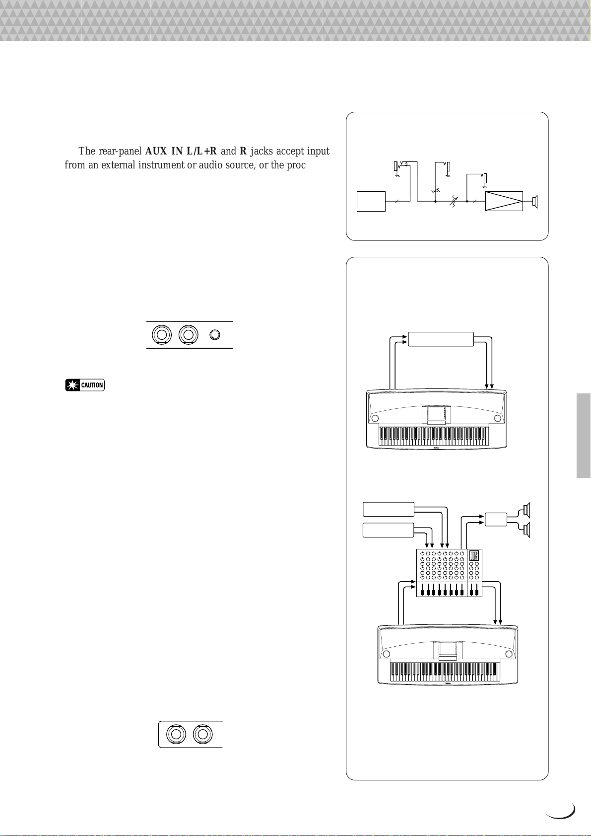
2 The AUX IN L/L+R and R (LOOP RETURN)
Jacks with TRIM Control..................................................
The rear-panel AUX IN L/L+R and R jacks accept input
from an external instrument or audio source, or the processed
signal returned from an external effect unit fed by the PSR-8000
LOOP SEND jacks, below . The signal received at the A UX IN/
LOOP RETURN jacks is mixed with PSR-8000 sound and
delivered via the speaker system. Use the L/L+R jack only for
monaural input.
The TRIM control allows the input sensitivity of the AUX
IN L/L+R and R (LOOP RETURN) jacks to be adjusted for
optimum level matching with the connected equipment.
Connections & Music Stand
Loop Signal Flow Diagram
LOOP SEND
MASTER EQ
L / R L / R
LOOP SEND/LOOP RETURN
Connection Examples
TRIM
MASTER VOLUME
AUX IN / LOOP RETURN
AUX OUT
POWER AMP
SP
AUX IN/LOOP RETURN
R L/L+R
MIN MAX
TRIM
• Never return the output from the AUX OUT jacks to the AUX IN
jacks. Also never return the output from an external device fed by
the AUX OUT jacks to the AUX IN jacks. Doing so can result in a
feedback loop which damage the PSR-8000 and connected equipment.
3 LOOP SEND L/L+R and R Jacks.............................
These jacks deliver the output of the PSR-8000 for connection to external signal processing devices such as reverb or
equalizer units. The output from the signal processor can be
returned to the AUX IN/LOOP RETURN jacks, described
above. When feeding a monaural device connect only the L/
L+R jack. When a plug is inserted into the L/L+R jack only, the
left- and right-channel signals are combined and delivered via
the L/L+R jack.
When a plug is inserted into the LOOP SEND L/L+ R jack
the internal signal flow is interrupted and only the signal
returned to the AUX IN (LOOP RETURN) jacks — see above
— will appear at the PSR-8000 speakers, headphones, and AUX
OUT jacks. No sound will be produced if the return signal is not
fed to the AUX IN (LOOP RETURN) jacks.
1. Stereo Effect Processor
Effector
LOOP SEND LOOP RETURN
L/L+R R L/L+R R
2. Mixer and Additional Sources
Sound Source
Sound Source
IN PUT STEREO OUT
IN PUT
Mixer
LOOP SEND
L/L+R R L/L+R R
MONITOR
OUT
LOOP RETURN
PA
LOOP SEND
R L/L+R
In this setup the sound of the PSR-8000 itself
as well as the external sources will be
reproduced via the PSR-8000 amplifier and
speakers, allowing the PSR-8000 to function
as a convenient stage monitor system.
13
Page 14
FOOT PEDAL
SWITCH 1 SWITCH 2 VOLUME
Connections & Music Stand
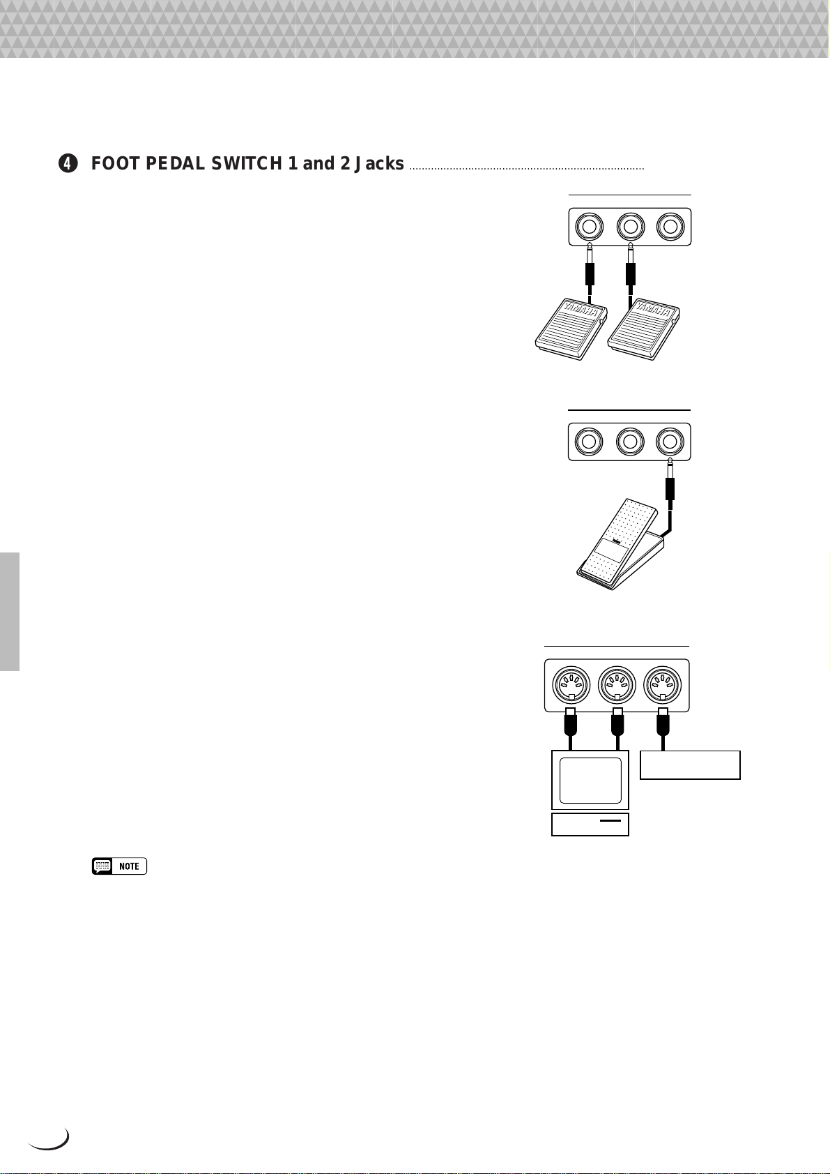
4 FOOT PEDAL SWITCH 1 and 2 Jacks ...................................................................................................................
One or two optional Y amaha FC5 footswitches connected to
these jacks can be used to control sustain and a range of other
important functions. Refer to the “FOOT SWITCH 1” and
“FOOT SWITCH 2” functions described on page 124.
5 FOOT PEDAL VOLUME Jack...........................................................................................................................................
An optional Y amaha FC7 Foot Controller can be connected
to this jack to allow foot volume (e xpression) control. The foot
FOOT PEDAL
SWITCH 1 SWITCH 2 VOLUME
controller can be assigned to control overall volume or the
volume of individual accompaniment and/or voices via the
“FOOT VOLUME” function — page 124.
6 MIDI IN, THRU and OUT Connectors......................................................................................................................
The MIDI IN connector recei ves MIDI data from an e xter -
nal MIDI device (such as a MIDI sequencer) which can be used
to control the PSR-8000. The MIDI THRU connector retransmits any data received at the MIDI IN connector , allowing
“chaining” of several MIDI instruments or other devices. The
MIDI OUT connector transmits MIDI data generated by the
PSR-8000 (e.g. note and velocity data produced by playing the
keyboard). More details on MIDI are provided on pages 132,
177. The PSR-8000 can also be connected directly to a personal
computer via the TO HOST connector, described belo w , without the need for a MIDI interface.
Computer
MIDI
IN OUT THRU
Music
Tone Generator
• Be sure to set the HOST SELECT switch to MIDI when using the MIDI
connectors. The MIDI connectors do not function when the HOST
SELECT switch is in any other position.
• No MIDI transmission or reception occurs in the SAMPLING mode.
14
Page 15
Connections & Music Stand
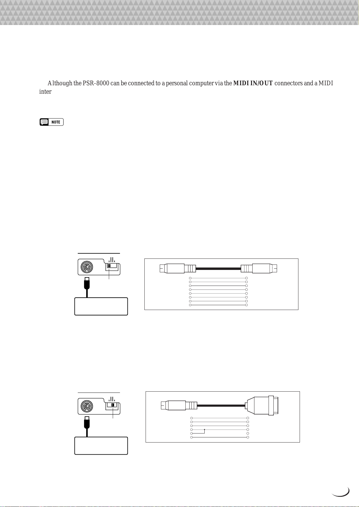
7 TO HOST Connector & HOST SELECT Switch ...........................................................................................
Although the PSR-8000 can be connected to a personal computer via the MIDI IN/OUT connectors and a MIDI
interface, the TO HOST connector and HOST SELECT switch allow direct connection to Apple Macintosh or IBM
PC/AT personal computers for sequencing and other music applications without the need for a separate MIDI
interface.
• When using the [TO HOST] terminal of the PSR-8000, first turn the power off on both the PSR-8000 and the computer before
connecting the cable. After connecting the cable, turn the power of the computer on first, then the PSR-8000.
• When not using the [TO HOST] terminal of the PSR-8000, make sure the cable is disconnected from the [TO HOST] terminal. If
the cable is left connected, the PSR-8000 may not function properly.
• When the HOST SELECT switch is set to “Mac”, “PC-1”, or “PC-2, no data transfer occurs via the MIDI connectors. To use the MIDI
connectors for connection via a standard MIDI interface, set the HOST SELECT switch to “MIDI”.
• No MIDI or TO HOST transmission or reception occurs in the SAMPLING mode.
● Connecting to an Apple Macintosh Series Computer ..................................................................
Connect the TO HOST connector of the PSR-8000 to the modem or printer port on your Macintosh, depending
on which port your MIDI software is using for MIDI data communication, using a standard Macintosh 8-pin system
peripheral cable. Set the HOST SELECT switch to the “Mac” position.
Y ou may also have to make other MIDI interface settings on the computer side, depending on the type of software
you use (refer to your software owner’s manual). In any case the clock speed should be set to 1 MHz.
TO HOST
PC-1 PC-2
MIDIMac
Set to the “Mac”
position.
Apple Macintosh
Series Computer
“Mac” Cable Connections
MINI DIN
8-PIN
• 8-pin system peripheral cable.
• Data transfer rate: 31,250 bps.
2 (HSK i)1
MINI DIN
1 (HSK 0)2
8-PIN
5 (RxD-)3
4 GND4
3 (TxD-)5
8 (RxD+)6
7 (GP i)7
6 (TxD+)8
● Connecting to an IBM-PC/AT Series Computer ...................................................................................
Connect the TO HOST connector of the PSR-8000 to the RS-232C port on your IBM computer , using a standard
8-pin MINI DIN → 9-pin D-SUB cross cable. Set the HOST SELECT switch to the “PC-2” position.
Refer to your software owner’s manual for information on any settings you might have to make on the computer
side.
TO HOST
PC-1 PC-2
MIDIMac
“PC-2” Cable Connections
Set to the “PC-2”
position.
IBM-PC/AT
Series Computer
MINI DIN
8-PIN
4 5 (GND)
8
• 8-pin mini DIN → 9-pin D-SUB cable.
• Data transfer rate: 38,400 bps.
8 (CTS)1
D-SUB
7 (RST)2
9-PIN
2 (RxD)3
3 (TxD) 5
15
Page 16
Connections & Music Stand
• If your system doesn’t work properly with the connections and settings listed above, your software may require different settings.
Check your software operation manual and if it requires a 31,250 bps. data transfer rate, set the HOST SELECT switch to “PC-1”.
• When using the TO HOST terminal to connect to a personal computer using Windows, a Yamaha MIDI driver must be installed in
the personal computer. The Yamaha MIDI driver can be obtained at Yamaha’s home page on the World Wide Web, <http://
www.yamaha.co.jp/english/xg/>.
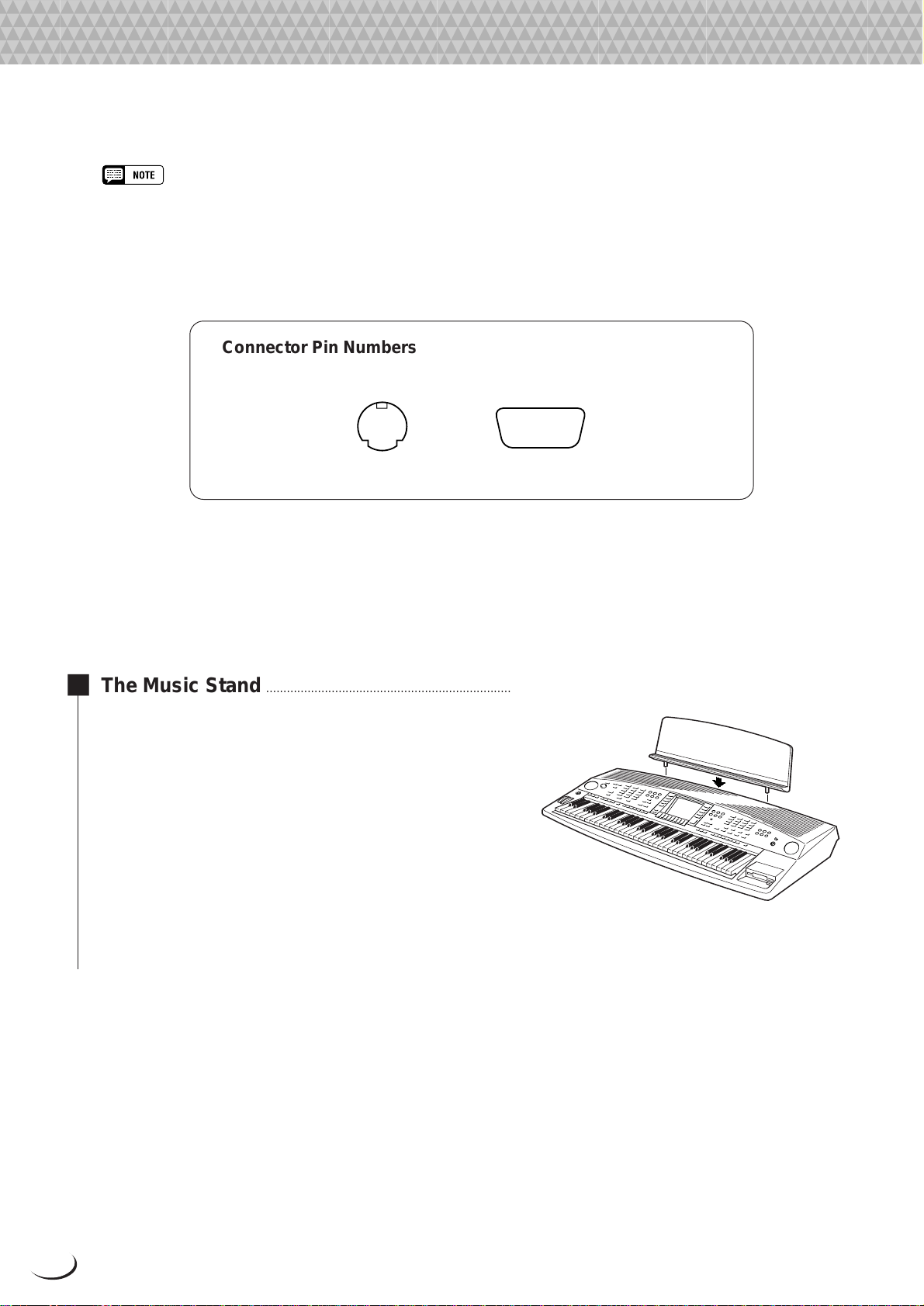
Connector Pin Numbers
MINI DIN 8-PIN
678
34
5
1
2
D-SUB 9-PIN
594837261
■ The Music Stand ..........................................................................................................................................................................
The PSR-8000 is supplied with a music stand that can be
attached to the instrument by inserting it into the holes at the
rear of the speaker panel.
16
Page 17
,,,,,,,,,,,,,,,,,
,
Q
¢
Y
QQQQQQQQQQQQQQQQQ
¢¢¢¢¢¢¢¢¢¢¢¢¢¢¢¢¢
The Demonstration
The Demonstration
To give you an idea of the PSR-8000’s sophisticated capabilities, it is
programmed with a number of demonstration sequences which can be
played in a number of w ays.
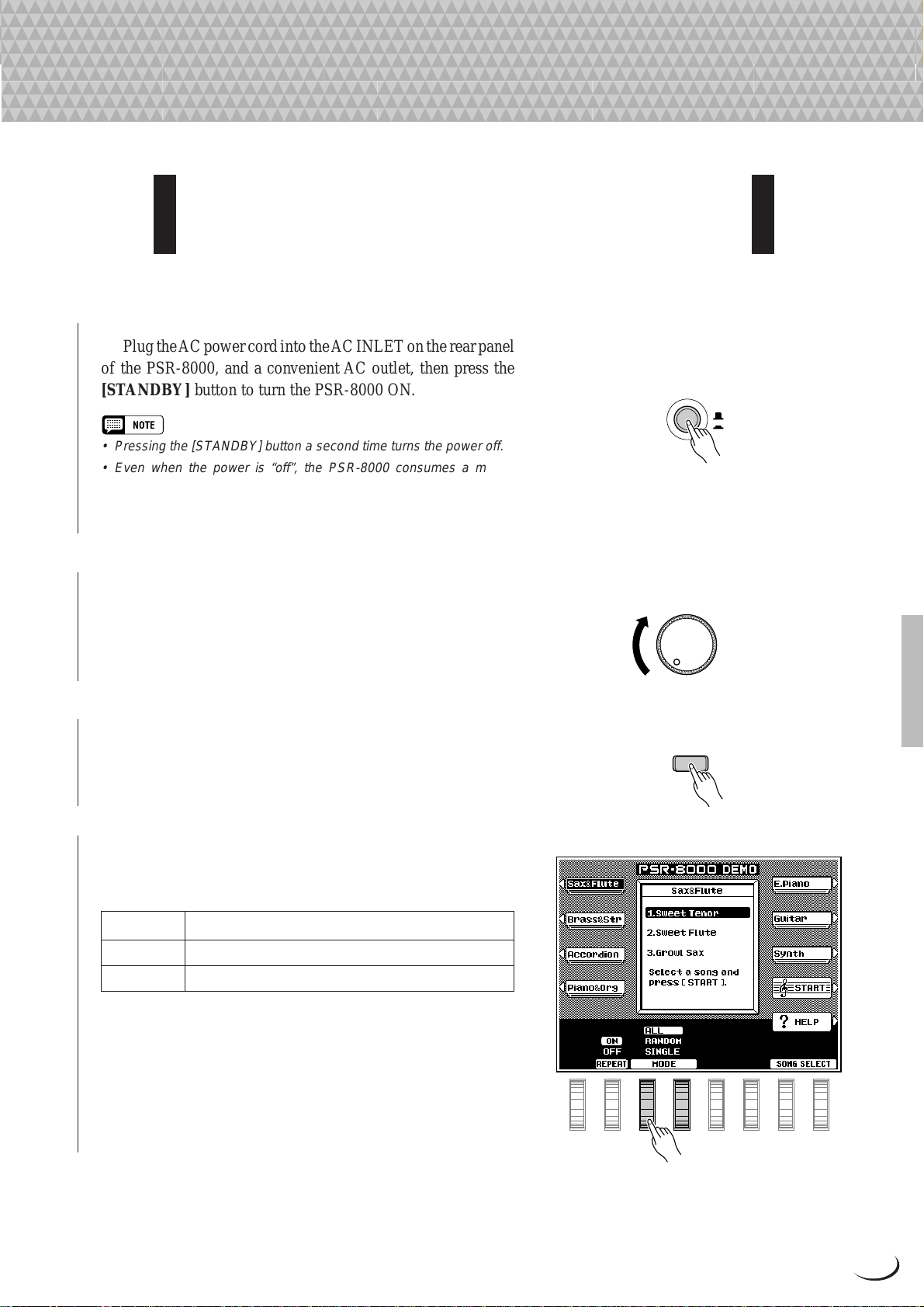
Z Switch ON............................................................................................................................................................................................
Plug the A C power cord into the AC INLET on the rear panel
of the PSR-8000, and a convenient AC outlet, then press the
[STANDBY] button to turn the PSR-8000 ON.
STAND B
ON
• Pressing the [STANDBY] button a second time turns the power off.
• Even when the power is “off”, the PSR-8000 consumes a minute
amount of power in order to maintain some internal memory contents.
Be sure to unplug the AC power cord from the AC outlet if you will not
be using the PSR-8000 for a long time.
X Set an Initial Volume Level................................................................................................................................................
Set the [MASTER VOLUME] control to a position about a
quarter of the way toward the highest setting. You can re-adjust
the [MASTER VOLUME] control for the most comfortable
overall volume level after playback begins.
MASTER VOLUME
MIN MAX
C Press the [DEMO/HELP] Button..................................................................................................................................
Press the [DEMO/HELP] button and the PSR-8000 demo
display will appear.
DEMO/HELP
V Select a Play Mode....................................................................................................................................................................
Use either of the LCD dials under MODE on the display to
select one of the available play modes.
ALL All demo songs are played back in sequence.
RANDOM All demo songs are played back in random order.
SINGLE Only the selected song is played.
17
Page 18
The Demonstration
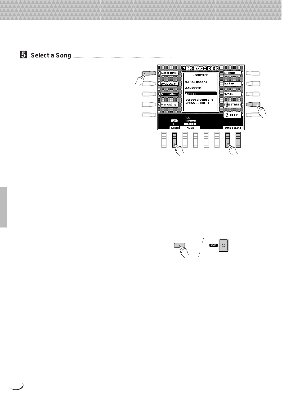
B Select a Song ..................................................................................................................................................................................
Press the LCD button corresponding to the
category containing of demo song you want to
play, then use the same LCD button to select a
demo song in that group. You can also use either
of the LCD dials under SONG SELECT on the
A
B
B
C
display to select any of the demo songs.
D
E
N Turn the Repeat Mode ON or OFF
Use the REPEAT LCD dial to turn repeat
playback ON or OFF as required (when ON, the
selected song or sequence of songs will be repeated until the STOP LCD button is pressed)
NB
F
G
H
I
M
J
M Start & Stop Playback as Re-
quired.........................................................................
Press the START LCD button to start playback
of the selected demo song(s). Press the STOP
LCD button when you want to stop playback.
< Exit When Done.............................................................................................................................................................................
Press either the [DEMO/HELP] button or the
[EXIT] button to exit from the demo mode and
return to the normal play-mode display when
you’ve finished playing the demo songs.
DEMO/HELP
18
Page 19
,,,,,,,,,,,,,,,,,
,
Q
¢
QQQQQQQQQQQQQQQQQ
¢¢¢¢¢¢¢¢¢¢¢¢¢¢¢¢¢
The PSR-8000 Display & Display-based Controls
The PSR-8000 Display & Display-based Controls
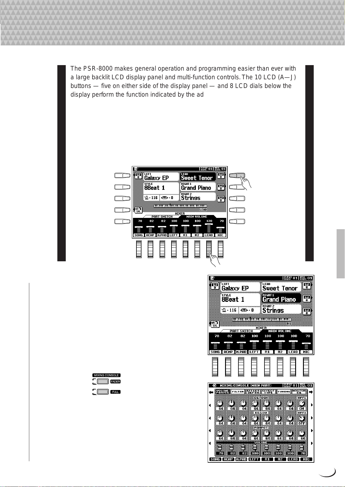
The PSR-8000 makes general operation and programming easier than ever with
a large backlit LCD display panel and multi-function controls. The 10 LCD (A—J)
buttons — five on either side of the display panel — and 8 LCD dials below the
display perform the function indicated by the adjacent section of the display.
In the example display shown here, for example, the LCD dial immediately
below LEAD on the display can be used to adjust the volume of the LEAD voice.
Rotate the dial upward to increase the volume, or rotate the dial downward to
decrease the volume.
In the same way, the LCD button immediately to the right of LEAD voice
window on the display is used to set the normal octave for the lead voice (“0”),
shift it one octave up (“+1”), or one octave down (“–1”).
A
B
C
D
E
■ The MIXING CONSOLE Buttons..............................
The lower section of the normal play mode display, shown
to the right, provides individual volume controls for the PSR8000’s song, accompaniment, multi pad, left, right 1, right 2,
lead, and microphone sound. Pressing the [FADER] button
alternately switches between this display and the individual
auto-accompaniment part volume controls: rhythm 1, rhythm 2,
bass, chord 1, chord 2, pad, phrase 1, and phrase 2. This is
essentially a “mixer” that you will use to achieve the best o verall
balance for your musical needs.
F
G
H
I
J
PART
PART
A full-screen mixing console which provides access to a
wide range of controls for each part can be selected by pressing
the [FULL] button. Full details are provided in the “The Mixing
Console” section on page 39.
19
Page 20
The PSR-8000 Display & Display-based Controls
The mixing console controls will disappear when functions
which have different displays are selected, b ut can be instantly
recalled without exiting from the current display mode by
• In the DEMO mode the mixer SONG parameters
become DEMO parameters.
pressing the [F ADER] or [FULL] button. Pressing the [EXIT]
button causes the mixer controls to disappear.
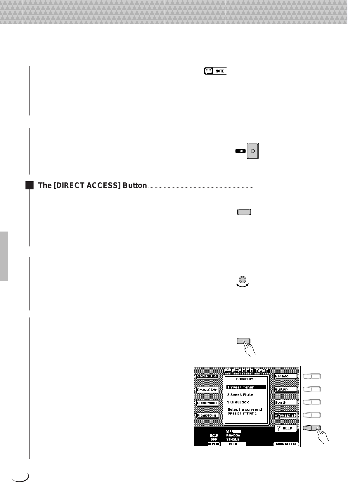
■ The [EXIT] Button .......................................................................................................................................................................
No matter where you are in the PSR-8000 display
hierarchy , the [EXIT] b utton will return you to the next
highest level, or to the normal play mode display.
■ The [DIRECT ACCESS] Button.....................................................................................................................................
Pressing a function button while holding the [DI-
RECT ACCESS] button will take you directly to a
parameter display related to that function. See page 170
DIRECT ACCESS
for a list of the applicable panel buttons and parameter
displays accessed.
■ The [LCD CONTRAST] Control ....................................................................................................................................
The PSR-8000 display panel is a liquid-crystal type
which features a [LCD CONTRAST] control. Use the
LCD CONTRAST
[LCD CONTRAST] control to set the display for optimum legibility.
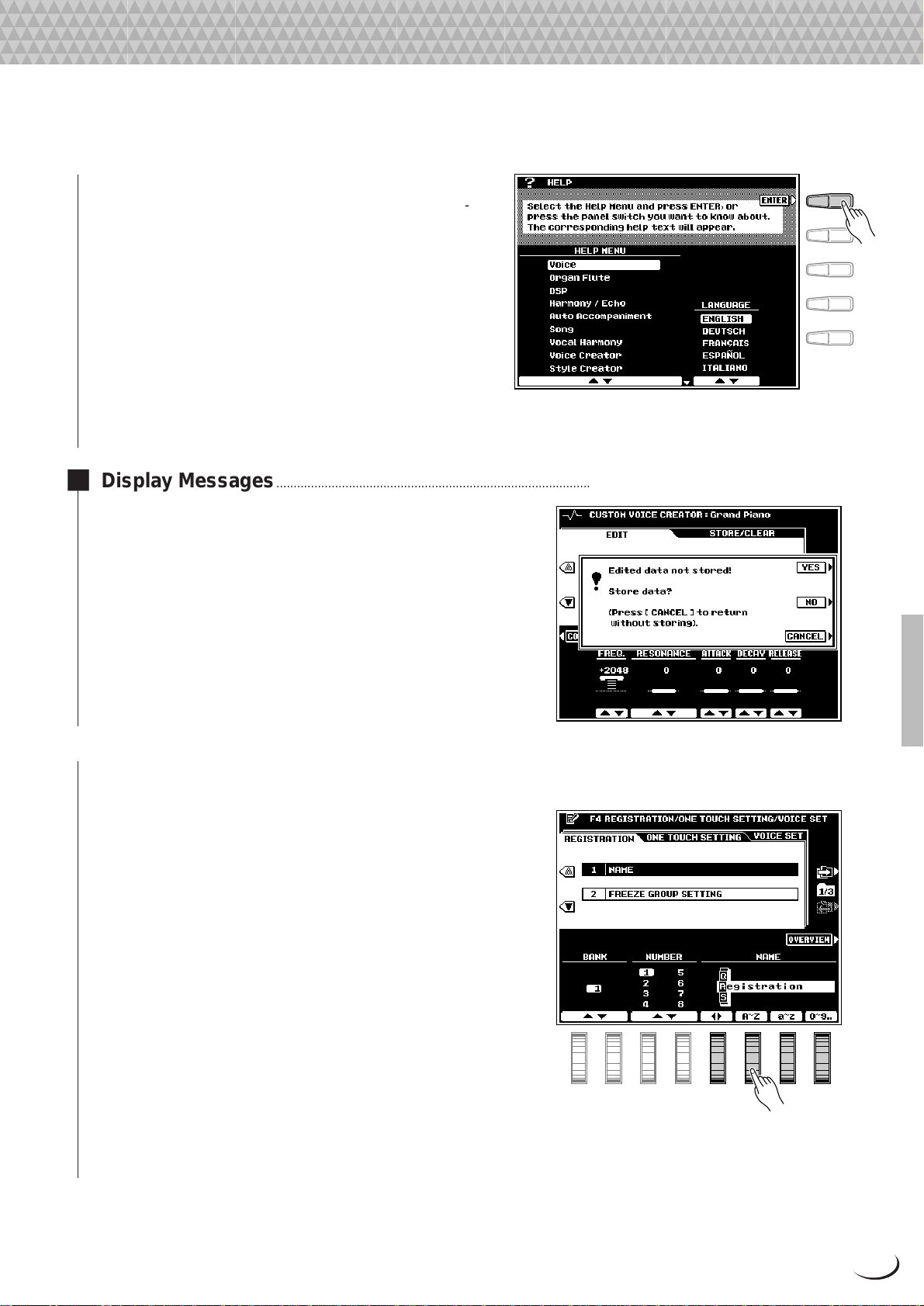
■ The 5-language Help Function .....................................................................................................................................
The PSR-8000 provides “on-line help” for its main
features and functions.
Press the [DEMO/HELP] button and then the HELP
LCD button to go to the main help display . Either select
an item from the HELP MENU by using one of the
corresponding LCD dials and then press the “ENTER”
LCD button, or simply press a panel button to see
corresponding help text. If more than one page of help
text is available for the selected topic, use the LCD
buttons to the right of the display to switch pages as
necessary. Press the RETURN TO HELP MENU LCD
button for more help, or the [EXIT] or [DEMO/HELP]
button when you’re ready to exit from the help mode.
DEMO/HELP
F
G
H
I
J
20
Page 21
The PSR-8000 Display & Display-based Controls
Help text and screen messages are available in five
languages: English, German, French, Spanish, and Italian. Use the LANGUAGE LCD dials in the help display
to select the desired language.
■ Display Messages.......................................................................................................................................................................
The large PSR-8000 display panel facilitates operation by
making it possible to display comprehensive message and
prompts that will guide you through certain operations. When
such messages appear, simply follow the instructions as sho wn.
F
G
H
I
J
■ Name Entry ........................................................................................................................................................................................
A number of PSR-8000 functions allow you to enter a name
for, for example, a f ile you will be saving to disk, a custom voice
or style, etc. The name entry procedure is essentially the same
in all cases (only the maximum number of characters which can
be entered will vary). An example display which includes
NAME entry parameters is shown below (the display shown
below can be accessed by pressing one of the REGISTRA-
TION MEMORY buttons — [1] … [8] — while holding the
[DIRECT ACCESS] button):
Use the < > LCD dial to move the name cursor to the
various character positions, then use the A~Z, a~z, or 0~9…
LCD dial to select the required character for each position. The
A~Z LCD dial selects capital letters, the a~z LCD dial selects
lower-case letters, and the 0~9… LCD dial selects numbers
and special characters.
21
Page 22
,,,,,,,,,,,,,,,,
,
Q
¢
QQQQQQQQQQQQQQQQ
¢¢¢¢¢¢¢¢¢¢¢¢¢¢¢¢
Playing the PSR-8000
Playing the PSR-8000
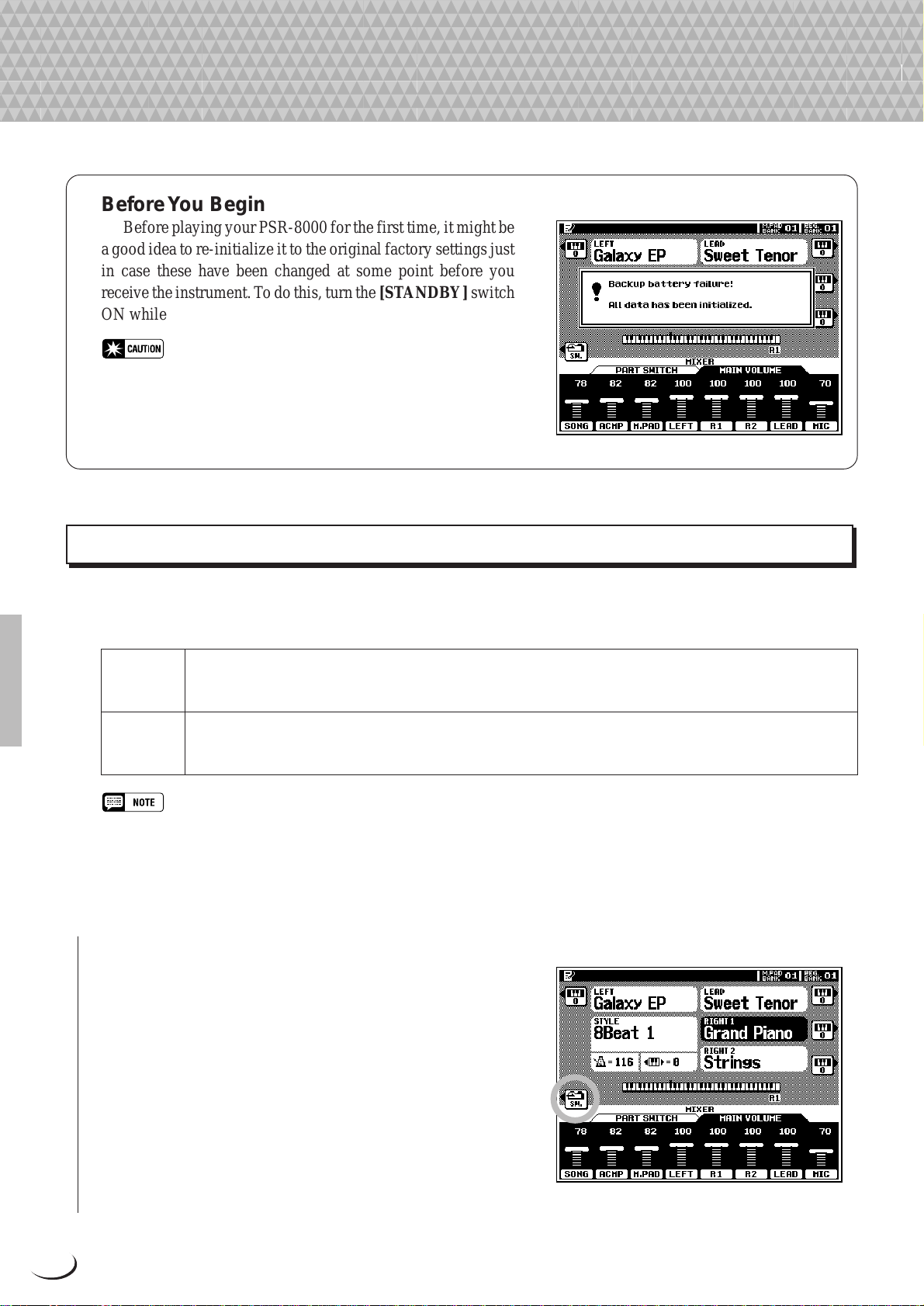
Before Y ou Begin
Before playing your PSR-8000 for the first time, it might be
a good idea to re-initialize it to the original factory settings just
in case these have been changed at some point before you
receive the instrument. To do this, turn the [ST ANDBY] switch
ON while holding the rightmost key on the keyboard (C6).
• When the above initialization procedure is carried out, all internal
data (e.g. REGISTRATION, CUSTOM OTS (One Touch Setting),
CUSTOM STYLE, GROOVE STYLE, CUSTOM VOICE, MULTI PAD)
will also be initialized and therefore lost!
The PSR-8000 Parts & Voices
The PSR-8000 allows you to individually select and play up to four “parts” at the same time in a number of w ays.
A range of voices can be assigned to each part.
RIGHT 1, The RIGHT 1, RIGHT 2, and LEAD voices can be played over the entire keyboard or to the right of a
RIGHT 2,
& LEAD
LEFT The LEFT can be played to the left of a specified split point while the RIGHT 1, RIGHT 2, and/or LEAD
• The split point can be set via the SPLIT POINT/FINGERING FUNCTION display described on page 123.
• The SPLIT POINT/FINGERING FUNCTION display can be accessed directly by pressing the [AUTO ACCOMPANIMENT] button
while holding the [DIRECT ACCESS] button.
■ Part Poly/Mono Modes & Mono Note Priority...............................................................................................
Each of the PSR-8000 voice “parts” can be switched to the
polyphonic or monophonic mode as required via the PART
SWITCH display accessed by pressing the PART LCD button
in the normal play mode while the F ADER mixer MAIN PART
display is selected (page 19).
specified split point (see “NOTE”, below). These v oices can be played individually or in any combination.
The RIGHT 1, RIGHT 2, and LEAD voices can be selected from a range of voices organized in 15 groups.
voices are played to the right of the split point. The LEFT voice can be selected from the same range of
voices as the RIGHT and LEAD parts.
Use the LEFT, RIGHT 1, RIGHT 2, and LEAD LCD dials to
set the corresponding parts to POL Y (polyphonic) or an y of the
three MONO (monophonic) note priority modes:
22
Page 23
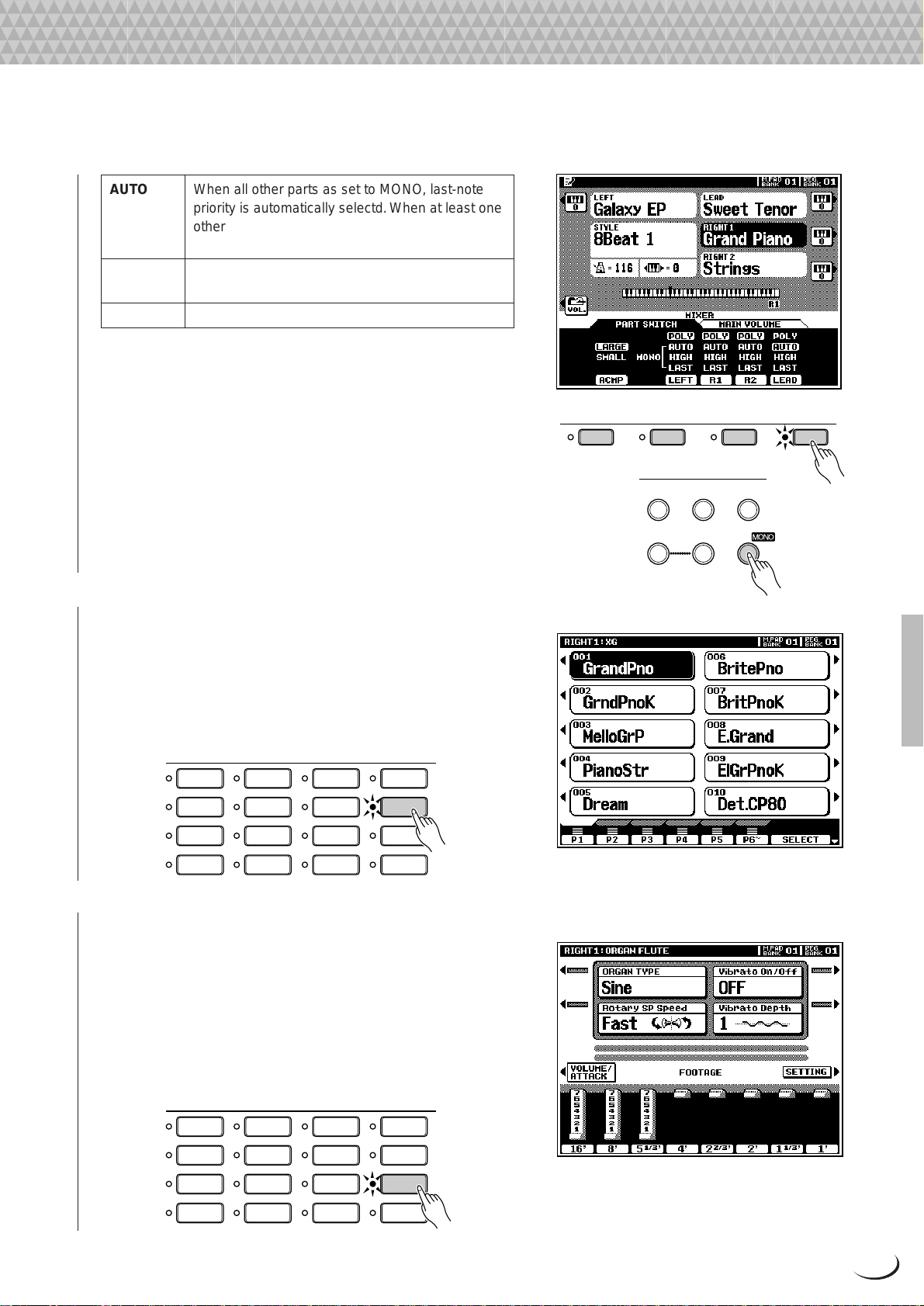
AUTO When all other parts as set to MONO, last-note
PART SELECT
LEFT RIGHT 1 RIGHT 2 LEAD
priority is automatically selectd. When at least one
other part is set to POLY, high-note priority is
automatically selected.
HIGH High-note priority. I.e. the highest note played on
the keyboard sounds.
LAST Last-note priority. I.e. the last note played sounds.
Poly/mono switching for each individual part can also be
carried out via the panel VOICE EFFECT [POLY/MONO]
button. Use the PART SELECT buttons to select the part you
want to switch, then use the [POLY/MONO] button to switch
selected part to the POLY (button indicator out) or MONO
(button indicator lit) mode. When the MONO mode is selected
via the [POLY/MONO] button, the last selected MONO note
priority mode will be selected.
Playing the PSR-8000
VOICE EFFECT
REVERB(1) CHORUS(2)
DSP(4-6)
DSP
VARIATION
HARMONY/
ECHO
POLY/
■ The XG Voices.................................................................................................................................................................................
Yamaha’s XG format is a major new enhancement to the GM
(General MIDI) System Level 1 format. It provides a larger
number of voices as well as greater expressive control and a
wide range of effects. XG also ensures continued compatibility
with future instruments and software.
VOICE
PIANO GUITAR
E.PIANO STRINGS
TRUMPETORGAN
ACCORDION
BRASS
SAXOPHONE PERCUSSION
FLUTE
CHOIR&PAD
SYNTHESIZER
XG
ORGAN
FLUTE
CUSTOM
VOICE
■ The Organ Flute Voice............................................................................................................................................................
The PSR-8000 has an ORGAN FLUTE voice which can be
assigned to the RIGHT, LEAD and LEFT voices in the same
way as the other voices. The main difference between the
ORGAN FLUTE voice and others is that the ORGAN FLUTE
voice can be directly edited via the display accessed by pressing
the [ORGAN FLUTE] VOICE button. Details on editing the
ORGAN FLUTE voice are provided on page 48.
VOICE
PIANO GUITAR
E.PIANO STRINGS
ACCORDION
TRUMPETORGAN
BRASS
SAXOPHONE PERCUSSION
FLUTE
CHOIR&PAD
SYNTHESIZER
XG
ORGAN
FLUTE
CUSTOM
VOICE
23
Page 24
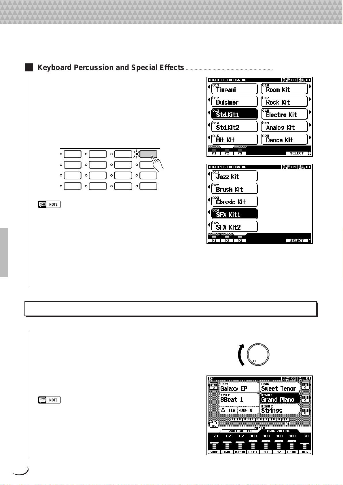
Playing the PSR-8000
■ Keyboard Percussion and Special Effects ......................................................................................................
When one of the Drum Kit or SFX Kit voices in the [PERCUSSION] group is selected, you can play 61 different drums and
percussion instruments or SFX (special effects) sounds on the
keyboard. The drum and percussion instruments played by the
various keys are marked by symbols abo ve the keys. Some of the
instruments in the different drum kit voices sound dif ferent even
though they have the same name, while others are essentially
the same.
VOICE
PIANO GUITAR
SAXOPHONE PERCUSSION
E.PIANO STRINGS
TRUMPETORGAN
ACCORDION
• The instrument symbols above the keyboard correspond to the actual
instrument sounds only when the default MIXER and normal play mode
OCTAVE settings apply. If the OCTAVE settings are altered the
instruments will shift position accordingly.
• See page 166 for a complete listing of the Drum Kit and SFX Kit
assignments.
• The Transpose, Tune, Sustain, Harmony, Left Hold, and Modulation
functions do not affect the Drum Kit or SFX Kit voices.
• The pitch bend wheel can be used to bend the pitch of the keyboard
percussion and SFX voices to create unique musical effects, but it has
little effect on some percussion sounds.
BRASS
FLUTE
CHOIR&PAD
SYNTHESIZER
XG
ORGAN
FLUTE
CUSTOM
VOICE
Procedure: Part Selection and Voice Assignment
Z Set Initial Volume Levels .....................................................................................................................................................
Set the [MASTER VOLUME] control to an appropriate
level, and make sure that the LEFT, R1, R2, and LEAD volume
levels in the MIXING CONSOLE MAIN VOLUME display
are set to their maximum “127” levels (use the corresponding
LCD dials to set these volume levels if necessar y). You can set
the [MASTER VOLUME] control for the most comfortable
overall volume level after beginning to play.
• No sound will be produced if all volume levels other than the [MASTER
VOLUME] control are set to their minimum values.
24
MASTER VOLUME
MIN MAX
Page 25
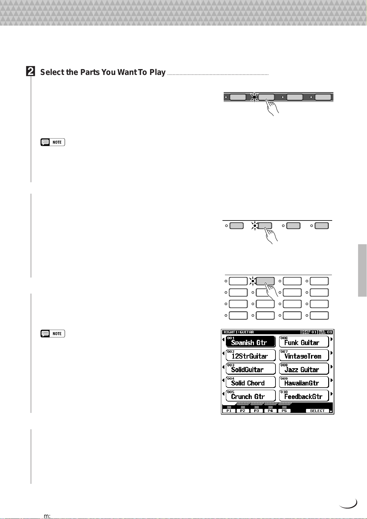
Playing the PSR-8000
X Select the Parts You Want To Play .............................................................................................................................
Press the [RIGHT 1], [RIGHT 2], [LEAD], and/or [LEFT]
PART ON/OFF button(s), turning on the indicators corre-
LEFT RIGHT 1 RIGHT 2 LEAD
PART ON/OFF
sponding to the parts you want to play . When a part is turned on
the corresponding voice in the main play mode display will be
highlighted (i.e. inverted — white characters against a dark
background).
• The more parts you play simultaneously, the fewer the total number of
notes that can be played on the keyboard at the same time.
• When the LEFT part is on, the left voice will automatically be transposed
up one octave.
C Select the Part You Want to Assign a Voice To.............................................................................................
The PART SELECT buttons above the PART ON/OFF
buttons determine which part is selected for voice assignments.
If you want to change the voice assigned to the RIGHT 1 part,
for example, the [RIGHT 1] P ART SELECT indicator must be
lit. Each time you turn a part on using the PART ON/OFF
buttons, the corresponding PART SELECT button indicator
will light automatically. You can also directly press any of the
P ART SELECT buttons. Only one P ART SELECT button can
be active at a time.
V Select a Voice ..............................................................................
Use the VOICE group buttons to select the group from
which you want to select a voice. The corresponding voice
display will appear.
LEFT RIGHT 1 RIGHT 2 LEAD
PIANO GUITAR
E.PIANO STRINGS
ACCORDION
TRUMPETORGAN
BRASS
PART SELECT
VOICE
SAXOPHONE PERCUSSION
FLUTE
CHOIR&PAD
SYNTHESIZER
XG
ORGAN
FLUTE
CUSTOM
VOICE
• Custom voices which can be selected via the [CUSTOM VOICE] button
can be created via the CUSTOM VOICE CREATOR mode described
on page 51, or loaded from disk.
Use the page-number LCD dials to select the page containing the voice you want if more than one page is av ailable, then
press the LCD button corresponding to the desired voice. You
can also use either of the SELECT LCD dials to select any of the
voices within the selected group.
B Play & Adjust Volume .............................................................................................................................................................
You can now play the selected voice or voices on the
keyboard. Use the [MASTER V OLUME] control to adjust the
overall volume level, and the MIXING CONSOLE MAIN
VOLUME LCD dials to set the desired balance between the
parts.
25
Page 26
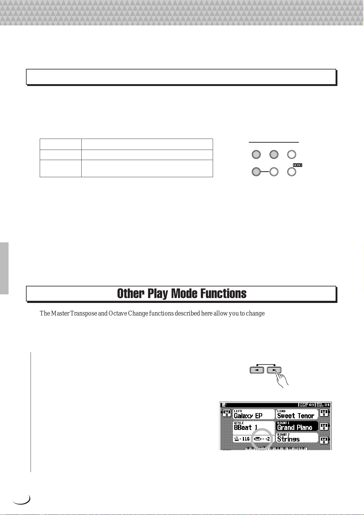
Playing the PSR-8000
VOICE EFFECT
REVERB(1) CHORUS(2)
HARMONY/
ECHO
DSP(4-6)
DSP
VARIATION
POLY/
Voice Effects
The PSR-8000 features a sophisticated multi-processor effect system which can add extraordinary depth and
expression to your sound. 7 independent digital signal processing (DSP) blocks are provided for effects, plus the
Vocal Harmony processor and 5-band Master EQ. Each DSP block applies to a specific part or portion of the PSR8000 sound. Some DSP block numbers appear next to the panel VOICE EFFECT buttons:
REVERB(1) Overall reverb
CHORUS(2) Overall chorus.
DSP(4-6) Independent effects for the RIGHT 1, RIGHT 2,
and LEAD parts.
There’s also a DSP VARIATION effect which can be applied to DSP(4-6) when the DSP(4-6) effect is on. T he
VOICE EFFECT b uttons turn the corresponding effects on (indicator lit) or off (indicator out) for the part currently
selected via the P ART SELECT b uttons. Independent V OICE EFFECT settings can be made for each part. You can
use the default effects, or reprogram them as required via the FULL MIXING CONSOLE, EFFECT DEPTH and
EFFECT TYPE displays (pages 41, 42).
The HARMONY/ECHO effect is described on page 37, and the operation of the POLY/MONO button is
described on page 22.
Other Play Mode Functions
The Master Transpose and Octa ve Change functions described here allow you to change the overall pitch of the PSR8000, or the octave of individual parts as required. The Left Hold function can be used to provide extra LEFT part
sustain.
■ Master Transpose........................................................................................................................................................................
This functions allow the overall pitch of the PSR-8000 to be
transposed up or down over a range of ±2 octaves in semitone
steps.
Use the MASTER TRANSPOSE [<] and [>] buttons to
set the transposition value as required. The current amount of
transposition appears in the transpose section of the normal play
mode display: from “–24” through “0” to “+24”.
Normal pitch (transpose value “0”) can be recalled at any
time by pressing both the MASTER TRANSPOSE [<] and
[>] buttons simultaneously.
RESET
MASTER TRANSPOSE
26
Page 27
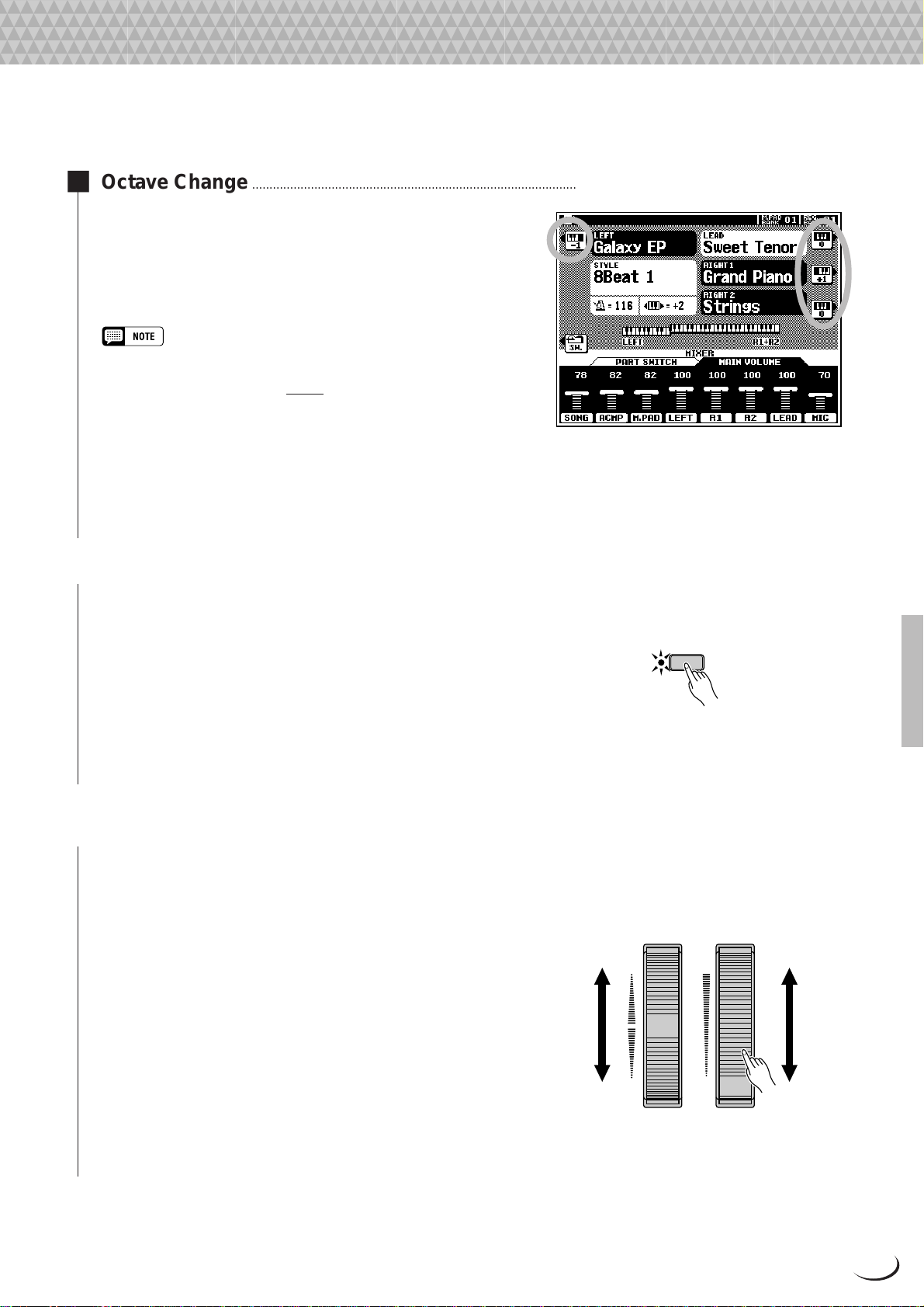
Playing the PSR-8000
■ Octave Change ..............................................................................................................................................................................
This function allows the LEFT , RIGHT 1, RIGHT2, and LEAD
parts to be independently transposed up or down by one octave.
The LEFT, RIGHT1, RIGHT2, LEAD LCD buttons (with
the small keyboard icons) directly set the octave of the corresponding part to “+1”, “–1”, and then “0”, in sequence.
• These parameters are separate from the OCTAVE parameters ac-
cessed via the FULL mixing console display (page 44). The values of
these octave parameters are
parameters.
• Some voices may suddenly shift octaves when played at the extreme
ends of the keyboard if they are set to a lower or higher octave and/or
transpose value than normal. This can also occur when the PITCH
BEND wheel is used on extremely low or high notes.
• If you change the transpose or octave change settings while playing
one or more notes on the keyboard, the new settings will take effect
from the next notes played.
added to those of the mixer’s OCTAVE
■ Left Hold ...............................................................................................................................................................................................
This function causes the LEFT part voice to be held even when
the keys are released. Non-decaying voices such as strings are
LEFT HOLD
held continuously, while decay-type v oices such as piano decay
more slowly (as if the sustain pedal has been pressed). Press the
[LEFT HOLD] button so that its indicator lights to engage the
LEFT HOLD function. Press the [LEFT HOLD] button a
second time so that the indicator goes out to turn LEFT HOLD
off.
■ Pitch Bend & Modulation Wheels..............................................................................................................................
The PITCH BEND and MODULATION wheels to the left of
the PSR-8000 keyboard can be used to add expressiv e variation
to your sound.
The range of the PITCH BEND wheel can be indpendently
set for the LEFT , RIGHT 1, RIGHT 2, and LEAD parts via the
FULL MIXING CONSOLE TUNING display (page 44).
The type of modulation applied by the MODULATION
wheel is preset for each of the PSR-8000’s preset voices. You
can assign your own modulation effects when creating CUSTOM VOICE (page 51). The MODULATION wheel can be
independently turned on or off for the LEFT , RIGHT 1, RIGHT
2, and LEAD parts via the F3: CONTROLLER, PANEL CON-
TROLLER display (page 126).
PITCH BEND
UP
DOWN
MODULATION
MAX
MIN
27
Page 28
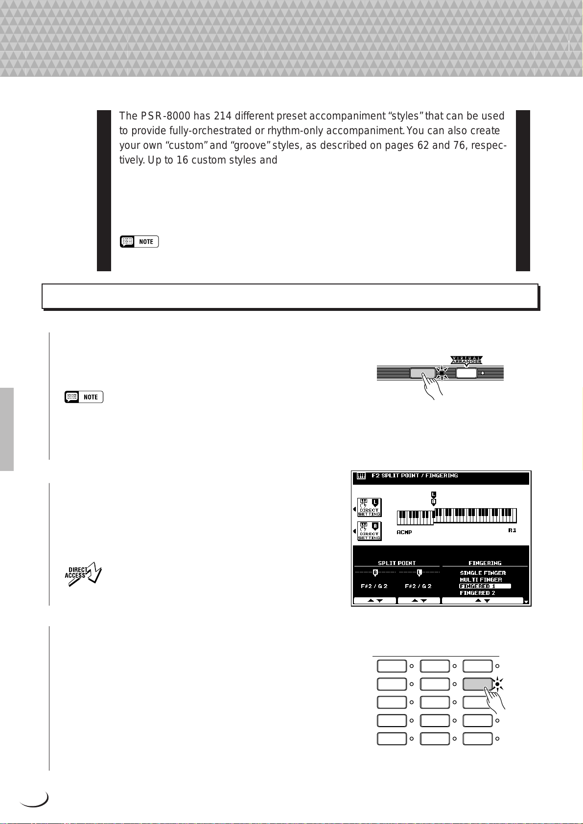
,,,,,,,,,,,,,,,,
,
Q
¢
QQQQQQQQQQQQQQQQ
¢¢¢¢¢¢¢¢¢¢¢¢¢¢¢¢
Using the Accompaniment Section
Using the Accompaniment Section
The PSR-8000 has 214 different preset accompaniment “styles” that can be used
to provide fully-orchestrated or rhythm-only accompaniment. You can also create
your own “custom” and “groove” styles, as described on pages 62 and 76, respectively. Up to 16 custom styles and 20 groove styles can be retained in the PSR8000 memory — more can be saved to disk for later loading and use.
The PSR-8000’s sophisticated auto-accompaniment system can provide
automated bass and chord backing that is perfectly matched to the selected
accompaniment style.
• The supplied floppy disk includes additional style files which can be used after being loaded into the PSR-
8000 (see page 140 for loading instructions).
Procedure: Auto Accompaniment
Z Turn AUTO ACCOMPANIMENT ON...........................................................................................................................
Press the [AUT O A CCOMP ANIMENT] button so that its
AUTO
indicator lights, thereby turning the AUTO ACCOMPANI-
ACCOMPANIMENT
MENT mode on.
• Rhythm-only accompaniment will be produced if you don’t turn the
[AUTO ACCOMPANIMENT] button on.
• The maximum number of notes that can be played simultaneously on
the PSR-8000 keyboard is reduced when the AUTO ACCOMPANIMENT feature is used.
X Select the Desired Fingering Mode.....................
Select the desired auto accompaniment fingering mode via
the SPLIT POINT/FINGERING FUNCTION display described on page 123. The operation of each mode is described
in “Auto Accompaniment Fingering Modes”, page 30.
• Press the [AUTO ACCOMPANIMENT] button while holding
the [DIRECT ACCESS] button to jump directly to the SPLIT
POINT/FINGERING display (page 123).
C Select a Style...................................................................................................................................................................................
The PSR-8000 has 214 preset styles organized in 13 groups
(see the “Style List” on page 168).
Use the STYLE group buttons to select the group from
which you want to select a style. The corresponding style
display will appear.
Use the page-number LCD dials to select the page containing the style you want if more than one page is available, then
press the LCD button corresponding to the desired style. You
can also use either of the SELECT LCD dials to select any of the
styles within the selected group.
28
8BEAT 1
8BEAT 2
16BEAT
BALLAD
ROCK
STYLE
DANCEFLOOR
DISCO
SWING &
JAZZ
R & B
COUNTRY
LATIN
BALLROOM
MARCH &
WALTZ
GROOVE
STYLE
CUSTOM
STYLE
Page 29
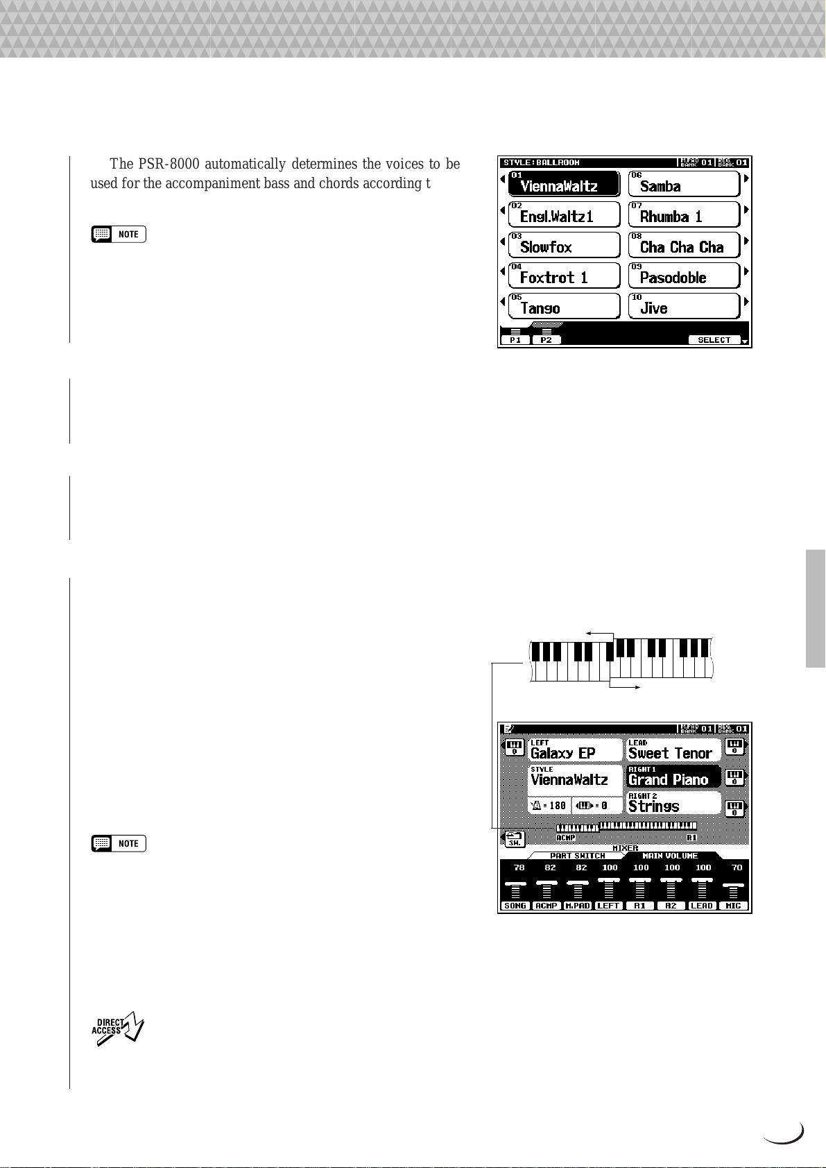
Using the Accompaniment Section
The PSR-8000 automatically determines the voices to be
used for the accompaniment bass and chords according to the
accompaniment style you select.
• Custom and groove styles which can be selected via the [CUSTOM
STYLE] and [GROOVE STYLE] buttons can be created as described
on pages 62 and 76, respectively, or loaded from disk.
• Styles loaded from the floppy disk provided with the PSR-8000 or
optional SFF (Style File Format) disks can also be used as CUSTOM
STYLES.
V Set the Tempo .................................................................................................................................................................................
If necessary , set the playback tempo as required (see “Tempo
Control, page 35).
B Start the Accompaniment..................................................................................................................................................
Use one of the start modes described in “Auto Accompaniment Start Modes”, below, to start the accompaniment.
N Play On the AUTO ACCOMPANIMENT Section Of the Keyboard............................................
As soon as you play any chord that the PSR-8000 can
“recognize” on the AUTO ACCOMPANIMENT section of the
keyboard (to the left of the auto accompaniment split point —
F#2 by default), the PSR-8000 will automatically begin to play
the chord along with the rhythm and an appropriate bass line.
The accompaniment will continue playing even if you release
the left-hand keys. See “ Auto Accompaniment Fingering Modes”,
below, for information on the individual fingering modes.
If the MANUAL BASS mode is selected only the rhythm
accompaniment will play automatically, and the bass v oice set
for the style can be played on the AUTO ACCOMP ANIMENT
section of the keyboard.
• The AUTO ACCOMPANIMENT section split point can be changed via
the SPLIT POINT/FINGERING FUNCTION display, described on page
123.
• The appropriate chord and bass note will sound if you play in the AUTO
ACCOMPANIMENT section of the keyboard while the AUTO ACCOMPANIMENT function is on but the accompaniment is stopped (but not
in the FULL KEYBOARD and MANUAL BASS modes).
• The four LED dots of the TEMPO display provide a visual indication of
the selected tempo.
Auto Accompaniment Section
Split Point
▼
3
C
Melody Section
• The SPLIT POINT/FINGERING display can be accessed
directly by pressing the [AUTO ACCOMPANIMENT] button
while holding the [DIRECT ACCESS] button.
29
Page 30
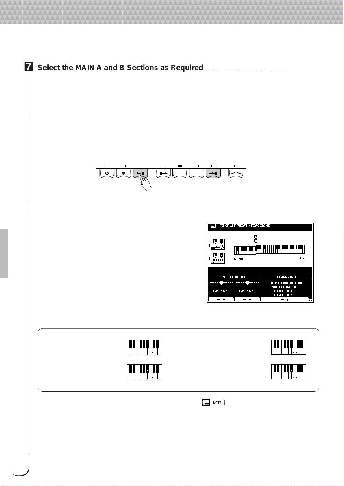
Using the Accompaniment Section
M Select the MAIN A and B Sections as Required........................................................................................
Select the MAIN A and MAIN B sections as required. Appropriate f ill-ins will be generated automatically (see “The
MAIN A and MAIN B Sections and Fill-ins”, page 34).
< Stop the Accompaniment..................................................................................................................................................
The accompaniment can be stopped at any time by pressing the [ST AR T/STOP] button. Press the [ENDING A/
B /rit.] button if you want to go to the ending section and then stop. A different ending will play depending on whether
you go to the ending from the MAIN A or MAIN B section. Press the [ENDING A/B /rit.] b utton while the ending
section is playing to produce a “ritardando” ending — i.e. the tempo gradually slows down during the ending.
SYNC
SYNC
STOP
START
START/
STOP
INTRO A/B MAIN/AUTO FILL
ACCOMPANIMENT CONTROL
A B
ENDING A/B
/rit.
FADE
IN/OUT
■ Auto Accompaniment Fingering Modes............................................................................................................
The PSR-8000 AUTO ACCOMPANIMENT feature has six
different fingering modes which can be selected via the SPLIT
POINT/FINGERING FUNCTION display described on page
123. Operation of each mode is described below.
● SINGLE FINGER
Single-finger accompaniment makes it simple to produce beautifully orchestrated accompaniment using major, seventh, minor and minor-seventh c hords by pressing a minimum number
of keys on the AUTO ACCOMPANIMENT section of the
keyboard. The abbreviated chord fingerings described below
are used:
●
For a major chord, press the
root key only.
●
For a minor chord, simultaneously press the root key and
a black key to its left.
C
Cm
●
For a seventh chord, simultaneously
press the root key and a white key to
its left.
●
For a minor-seventh chord, simultaneously press the root key and both a
white and black key to its left.
C
Cm
7
7
● MULTI FINGER
The MULTI-FINGER mode automatically detects SINGLE
FINGER or FINGERED 1 chord fingerings, so you can use
either type of fingering without having to switch fingering
modes.
30
• To use SINGLE FINGER minor, minor-seventh, or
seventh fingerings in the MULTI FINGER mode, be
sure to play the closest white/black key(s) to the root
of the chord.
Page 31

Using the Accompaniment Section
● FINGERED 1
The FINGERED 1 mode lets you finger your own chords on the AUTO ACCOMP ANIMENT section of the keyboard,
while the PSR-8000 supplies appropriately orchestrated rhythm, bass, and chord accompaniment in the selected
style.
The FINGERED 1 mode will accept the following chord types:
Chord Name [Abbreviation] Normal Voicing
Major [M] 1 - 3 - 5
Add ninth [(9)] 1 - 2 - 3 - 5
Sixth [6] 1 - (3) - 5 - 6
Sixth ninth [6(9)] 1 - 2 - 3 - (5) - 6
Major seventh [M7] 1 - 3 - (5) - 7 or
Major seventh ninth [M7(9)] 1 - 2 - 3 - (5) - 7
Major seventh add sharp eleventh [M7(#11)] 1 - (2) - 3 - #4 - 5 - 7 or
Flatted fifth [(b5)] 1 - 3 - b5
Major seventh flatted fifth [M7b5] 1 - 3 - b5 - 7
Suspended fourth [sus4] 1 - 4 - 5
Augmented [aug] 1 - 3 - #5
Major seventh augmented [M7aug] 1 - (3) - #5 - 7
Minor [m] 1 - b3 - 5
Minor add ninth [m(9)] 1 - 2 - b3 - 5
Minor sixth [m6] 1 - b3 - 5 - 6
Minor seventh [m7] 1 - b3 - (5) - b7
Minor seventh ninth [m7(9)] 1 - 2 - b3 - (5) - b7
Minor seventh eleventh [m7(11)] 1 - (2) - b3 - 4 - 5 - (b7)
Minor major seventh [mM7] 1 - b3 - (5) - 7
Minor major seventh ninth [mM7(9)] 1 - 2 - b3 - (5) - 7
Minor seventh flatted fifth [m7b5] 1 - b3 - b5 - b7
Minor major seventh flatted fifth [mM7b5] 1 - b3 - b5 - 7
Diminished [dim] 1 - b3 - b5
Diminished seventh [dim7] 1 - b3 - b5 - 6
Seventh [7] 1 - 3 - (5) - b7 or
Seventh flatted ninth [7(b9)] 1 - b2 - 3 - (5) - b7
Seventh add flatted thirteenth [7(b13)] 1 - 3 - 5 - b6 - b7
Seventh ninth [7(9)] 1 - 2 - 3 - (5) - b7
Seventh add sharp eleventh [7(#11)] 1 - (2) - 3 - #4 - 5 - b7 or
Seventh add thirteenth [7(13)] 1 - 3 - (5) - 6 - b7
Seventh sharp ninth [7(#9)] 1 - #2 - 3 - (5) - b7
Seventh flatted fifth [7b5] 1 - 3 - b5 - b7
Seventh augmented [7aug] 1 - 3 - #5 - b7
Seventh suspended fourth [7sus4] 1 - 4 - (5) - b7
One plus two plus five [1+2+5] 1 - 2 - 5
1 - (3) - 5 - 7
1 - 2 - 3 - #4 - (5) - 7
1 - (3) - 5 - b7
1 - 2 - 3 - #4 - (5) - b7
Display for root “C”
C
C(9)
C6
C6(9)
CM7
CM7(9)
CM7#11
C(b5)
CM7b5
Csus4
Caug
CM7aug
Cm
Cm(9)
Cm6
Cm7
Cm7(9)
Cm7_11
CmM7
CmM7_9
Cm7b5
CmM7b5
Cdim
Cdim7
C7
C7(b9)
C7b13
C7(9)
C7#11
C7(13)
C7(#9)
C7b5
C7aug
C7sus4
C1+2+5
• Notes in parentheses can
be omitted.
• If you play any three
adjacent keys (including
black keys), the chord
sound will be canceled
and only the rhythm instruments will continue
playing (CHORD CANCEL function).
• Playing a single key or
two same root keys in the
adjacent octaves produces accompaniment
based only on the root.
• A perfect fifth (1 + 5)
produces accompaniment
based only on the root
and fifth which can be
used with both major and
minor chords.
• The chord fingerings
listed are all in “root”
position, but other inversions can be used — with
the following exceptions:
b
m7, m7
aug, dim7, 7
5, 6, m6, sus4,
b
5, 6(9),
m7_11, 1+2+5.
• Inversion of the 7sus4
chord is not recognized if
the 5th is omitted.
• The AUTO ACCOMPANIMENT will sometimes not
change when related
chords are played in
sequence (e.g. some
minor chords followed by
the minor seventh).
• Two-note fingerings will
produce a chord based
on the previously played
chord.
31
Page 32

Using the Accompaniment Section
Example for “C” chords
C
Csus
CmM
(9)
C
7
(9)
C
4
7
Caug
CmM
7
( )
#11
C
7
( )
( )
_9
( )
C
6
( )
CM aug
7
( )
b5
Cm
7
(13)
C
7
( )
(9)
C
6
Cm
CmM
C
7
(#9)
CM
7
Cm
Cdim
b5
C
7
( )
(9)
( )
b5
7
( )
● FINGERED 2
This mode accepts the same fingerings as the FINGERED 1
mode, but the lowest note played in the AUTO ACCOMPANIMENT section of the keyboard is used as the bass root, allowing
you to play “on bass” or “fraction” chords (in the FINGERED
1 mode the root of the chord is always used as the bass root).
(9)
CM
7
Cm
6
Cdim
C aug
7
#11
CM
7
( )
7
( )
Cm
7
C
7
C sus
7
( )
( )
4
( )
C
Cm
C
C
(b5)
(9)
7
(b9)
7
1+2+5
( )
( )
CM
Cm
C
b5
7
_11
7
( )
( )
b13
7
● FULL KEYBOARD
When this advanced auto-accompaniment mode is engaged the
PSR-8000 will automatically create appropriate accompaniment while you play just about anything, anywhere on the
keyboard using both hands. You don’t have to worry about
specifying the accompaniment chords. Although the FULL
KEYBOARD mode is designed to work with many songs, some
arrangements may not be suitable for use with this feature. Try
playing a few simple songs in the FULL KEYBOARD mode to
get a feel for its capabilities.
● MANUAL BASS
In this mode only the rhythm accompaniment will play automatically, and the bass voice set for the style can be played on
the AUTO ACCOMPANIMENT section of the keyboard. No
chord detection occurs.
• Chord detection occurs at approximately 8th-note
intervals. Extremely short chords — less than an 8th
note in length — may therefore not be detected.
• In all fingering modes except MANUAL BASS the
name of the detected chord will appear on the display.
32
Page 33

Using the Accompaniment Section
■ Auto Accompaniment Start Modes .........................................................................................................................
Add variety and interest to your accompaniment taking advantage of the many start variations described below.
● Straight Start
Press the [START/STOP] button. If you press the [START/
STOP] button, the rhythm will begin playing immediately
without bass and chord accompaniment.
• It is also possible to select the MAIN A or MAIN B section prior to a
straight start (MAIN A is the basic style pattern, MAIN B is a variation).
START/
STOP
● Synchronized Start
Any of the start types can be synchronized to the first note or
chord played on the A UTO A CCOMP ANIMENT section of the
keyboard by first pressing the [SYNC ST ART] b utton. Pressing
the [SYNC ST ART] button alone causes a straight start to occur
when the first note or chord is played. Press [SYNC START]
and the appropriate MAIN and/or INTRO buttons, as described
below, for a synchronized introduction start.
The first dot of the BEAT display above the TEMPO
buttons will flash at the current tempo when a synchronized
start mode has been selected.
• The Synchronized Start function can be cancelled before the accompaniment is actually started by pressing the [SYNC START] button a
second time so that its indicator goes out.
• If you press the [SYNC START] button while the accompaniment is
playing, the accompaniment will stop and the synchronized start mode
will be engaged.
• A Yamaha FC5 footswitch plugged into a rear panel FOOT PEDAL
SWITCH 1 or SWITCH 2 jack can also be used to start the accompaniment or control other style playback functions if the appropriate
function is assigned to the footswitch using the FOOT CONTROLLER
functions described on page 124.
1st Beat
2nd Beat
3rd Beat
4th Beat
SYNC
START
BEAT
TEMPO
RESET
4/4 Time 3/4 Time
BEAT
BEAT
BEAT
BEAT
BEAT
BEAT
BEAT
● Start with an introduction followed by the MAIN A or MAIN B variation
In addition to two MAIN variations, “A” and “B”, each PSR-8000 style has two intro variations which can be
followed by either the MAIN A or MAIN B variation.
To start with INTRO A and go to MAIN A, press the MAIN/AUTO FILL [A] button
so that its indicator lights (if it is not already lit), then press the [INTRO A/B] button, then
use a straight or synchronized start.
SYNC
SYNC
STOP
START
START/
STOP
INTRO A/B MAIN/AUTO FILL
A B
ENDING A/B
/rit.
FADE
IN/OUT
33
Page 34

Using the Accompaniment Section
To start with INTRO B and go to MAIN B, press the MAIN/AUTO FILL [B] button so
that its indicator lights (if it is not already lit), then press the [INTRO A/B] button, then use
a straight or synchronized start.
SYNC
SYNC
START
SYNC
START
START/
STOP
START/
STOP
STOP
To start with INTRO A and go to MAIN B, press the MAIN/AUTO FILL [A] button
so that its indicator lights (if it is not already lit), then press the [INTRO A/B] button, then
press the MAIN/AUTO FILL [B] button. Use a straight or synchronized start.
SYNC
STOP
INTRO A/B MAIN/AUTO FILL
A B
INTRO A/B MAIN/AUTO FILL
A B
ENDING A/B
/rit.
ENDING A/B
/rit.
FADE
IN/OUT
FADE
IN/OUT
To start with INTRO B and go to MAIN A, press the MAIN/A UTO FILL [B] button so
that its indicator lights (if it is not already lit), then press the [INTRO A/B] button, then
press the MAIN/AUTO FILL [A] button. Use a straight or synchronized start.
SYNC
SYNC
STOP
START
START/
STOP
INTRO A/B MAIN/AUTO FILL
A B
ENDING A/B
/rit.
FADE
IN/OUT
• The introduction can be cancelled before the accompaniment is actually started by pressing the [INTRO
A/B] button a second time so that its indicator goes out.
■ The MAIN A and MAIN B Sections and Fill-ins ...........................................................................................
The MAIN A and MAIN B sections can be selected at any
time during accompaniment playback by pressing the corresponding button. Whene ver you press the MAIN/A UTO FILL
[A] or [B] button during playback, the PSR-8000 will generate
an appropriate “fill-in” (one of four types: AA, AB, BA, and
BB) which will smoothly connect the current section to the
selected section — even if it is the same section. For e xample,
if you press the MAIN/AUTO FILL [A] button while the
MAIN A section is playing, a fill-in will be produced, then the
MAIN A section will continue playing. When you select a
different section, the fill-in will be gin immediately and the new
section will actually begin playing from the top of the next
measure unless the MAIN/AUTO FILL [A] or [B] button is
pressed during the last half-beat of the measure, in which case
the fill-in will begin from the first beat of the next measure.
MAIN/AUTO FILL
A B
34
Page 35

Using the Accompaniment Section
■ Tempo Control................................................................................................................................................................................
When you select a different style while the accompaniment
is not playing, the “default” tempo for that style is also selected,
and the tempo is displayed on the display in beats per minute.
If the accompaniment is playing, the same tempo is maintained
even if you select a diff erent style.
You can change the tempo to any value between 32 and 280
beats per minute, however, by using the TEMPO [<] and [>]
buttons. This can be done either before the accompaniment is
started or while it is playing. To use the [<] and [>] buttons,
press either button briefly to decrement or increment the tempo
value by one, or hold the button for continuous decrementing or
incrementing.
The default tempo for the selected style can be recalled at
any time by pressing both the TEMPO [<] and [>] buttons
simultaneously.
RESET
TEMPO
■ Fade-ins and Fade-outs .......................................................................................................................................................
The [FADE IN/OUT] button can be used to produce smooth
fade-ins and fade-outs when starting and stopping the accompaniment.
T o produce a fade-in, press the [FADE IN/OUT] button so
that its indicator lights before starting the accompaniment (the
fade-in can be cancelled by pressing the button a second time).
Then when the accompaniment is started the sound will gradually fade in. The [FADE IN/OUT] indicator will flash during
the fade-in, and then go out when full volume has been reached.
To produce a fade-out press the [FADE IN/OUT] button
while the accompaniment is playing. The indicator will flash
during the fade out, then the accompaniment will stop when the
fade-out is complete. The [FADE IN/OUT] button indicator
will remain lit for a few seconds after the fade-out, indicating
that the fade-in mode is engaged. Press the [FADE IN/OUT]
button so that its indicator goes out if you want to disengage the
fade-in mode.
FADE
IN/OUT
■ Synchronized Stop....................................................................................................................................................................
When the Sync Stop function is engaged, accompaniment
playback will stop completely when all keys in the auto accompaniment section of the keyboard are released. Accompaniment
playback will start again when a chord is played. The BEAT
indicators will flash while the accompaniment is stopped.
The Sync Stop function is engaged by pressing the [SYNC
STOP] button so that its indicator lights. Press the [SYNC
STOP] button again so that its indicator goes out to turn the
Sync Stop function off.
SYNC
STOP
• The Sync Stop function can only be used when AUTO
ACCOMPANIMENT is ON and the FULL KEYBOARD
fingering mode is
not selected.
35
Page 36

Using the Accompaniment Section
■ Accompaniment Volume......................................................................................................................................................
Use the various LCD dials in the MIXING CONSOLE [F ADER]
ACMP VOLUME display to set the best balance between the
corresponding accompaniment parts. The MAIN VOLUME
and ACMP VOLUME displays can be used to set the balance
between the keyboard and accompaniment sound (use the
[FADER] button to toggle between the MAIN VOLUME and
ACMP VOLUME displays).
PART
■ Accompaniment Part Switching .................................................................................................................................
The PART SWITCH buttons accessible via the MIXING
CONSOLE [FADER] ACMP VOLUME display make it pos-
sible to individually mute accompaniment parts to create the
blend and accompaniment “size” you want. W ith the MIXING
CONSOLE [FADER] ACMP VOLUME display showing,
press the LCD “SW.” button to bring the PART SWITCH
display to the front.
Use the LCD dials to turn the corresponding accompaniment
parts ON or OFF, as required.
The PART SWITCH display accessed from the MIXING
CONSOLE [FADER] MAIN VOLUME display additionally
includes an ACMP parameter with LARGE and SMALL settings (use the [FADER] button to toggle between the ACMP
and MAIN displays). These select different arrangement “sizes”
(i.e. more or less parts turned on or off).
■ Virtual Arranger............................................................................................................................................................................
When the Virtual Arranger function is turned on, the AUTO
ACCOMPANIMENT feature will play a more complex “arrangement” which provides livelier , more melodic accompaniment.
Turn the Virtual Arranger on by pressing the [VIRTUAL
ARRANGER] button so that its indicator lights. Press the
[VIRTUAL ARRANGER] button again so that its indicator
goes out to turn the function off.
AUTO
ACCOMPANIMENT
• The Virtual Arranger is only effective when AUTO ACCOMPANIMENT
is ON and the FULL KEYBOARD or MANUAL BASS fingering mode is
not selected.
• The Virtual Arranger will not work with custom styles.
36
Page 37

Using the Accompaniment Section
■ Harmony/Echo................................................................................................................................................................................
This feature adds harmony or embellishment notes to a melody
you play using the RIGHT 1, LEAD, or RIGHT 2 parts.
The PSR-8000 includes the following Harmony/Echo effects (these are independent from the DSP effects controlled via
the mixing console — page 42):
The effect to be applied, the volume of the effect in relation
to the keyboard sound, the speed of the repeat-based effects, and
the part(s) to which the effect will apply, can all be set via the
F5: HARMONY/ECHO function page described on page 129.
The PSR-8000 Harmony/Echo effect is engaged by pressing
the VOICE EFFECT [HARMONY/ECHO] button so that its
indicator lights. To turn Harmony/Echo off press the [HAR-
MONY/ECHO] button a second time so that the indicator goes
out.
• Press the [HARMONY/ECHO] button while holding the
[DIRECT ACCESS] button to jump directly to the F5:
HARMONY/ECHO function page.
• When multiple right-hand notes are played, Harmony/Echo is applied
to the last-played note (last-note priority).
• Harmony/Echo effects do not work with the Drum Kit or SFX Kit voices.
• In the AUTO ASSIGN mode, harmony is applied to the highest-priority
part among those currently turned on. The part priorities are, from
highest to lowest: R1
part to which harmony will be applied via the F5 HARMONY/ECHO
function page.
→
LEAD → R2. It is also possible to specify the
The Harmony/Echo Types
1 DUET
2 1+5
3 COUNTRY
4 TRIO
5 BLOCK
6 4WAY CLOSE 1
7 4WAY CLOSE 2
VOICE EFFECT
REVERB(1) CHORUS(2)
8 4WAY OPEN
9 OCTAVE
10 STRUM
11 MULTI ASSIGN
12 ECHO
13 TREMOLO
14 TRILL
HARMONY/
ECHO
● Harmony-based Effects
Types 1 through 8 and 10 are harmony effects which produce
harmony based on the current AUTO ACCOMPANIMENT
chord (see “NOTES” below for conditions).
• Harmony types 1 through 8 and 10 will function only when AUTO
ACCOMPANIMENT is ON and a fingering mode other than FULL
KEYBOARD or MANUAL BASS is selected.
• No harmony is produced when no chord is detected.
• Harmony types 1 through 8 and 10 produce unison harmony during
auto-accompaniment intros and endings.
● Repeat-based Effects & Multi Assign
Effects 9 and 12 through 14 are repeat-based effects which do
not depend on AUTO ACCOMPANIMENT chord detection.
These effects will function at any time (even when AUTO
ACCOMPANIMENT is off), except when the FULL KEYBOARD fingering mode is active.
The MUL TI ASSIGN effect (number 11) is a little dif ferent,
and may need some explanation. MULTI ASSIGN automati-
DSP(4-6)
DSP
VARIATION
POLY/
37
Page 38

Using the Accompaniment Section
ONE TOUCH SETTING
43
21
cally assigns notes played simultaneously on the right-hand
section of the keyboard to separate parts (voices). The number
of parts which can be assigned depends on the number of parts
• The TRILL effect applies when two right-hand notes
are played.
turned ON via the PART ON/OFF buttons. If three parts are
turned on, then up to three voices can be assigned. if two parts
are turned on, then only two voices can be assigned. For
example, if the R1, R2, and LEAD parts are turned on and you
play a C-major triad on the right-hand section of the keyboard
(C-E-G), then “C” will be played by the R1 voice, “E” by the R2
voice, and “G” by the LEAD voice.
■ One Touch Setting......................................................................................................................................................................
The PSR-8000 One Touch Setting function provides 4 preset
“setups” (i.e. sets of panel settings, including voices, effects,
etc.) for each of the 214 preset accompaniment styles. You can
also create your own One T ouch Setting setups for up to 8 styles
(4 setups per style). See page 127 for a complete list of the
parameters set by the One Touch Setting function.
To select a One Touch Setting setup for the current style,
simply press one of the panel ONE TOUCH SETTING but-
tons: [1] … [4]. The corresponding panel settings will be
recalled and the name of the selected setup will appear in the
upper left-hand corner of the display.
To create a custom setup, set the panel controls as required
then press one of the ONE TOUCH SETTING buttons while
holding the [MEMORY] button. Up to four custom setups can
be created for up to 8 styles. If the number of customizable
setups is exceeded, a message will appear asking if you want to
go to the F4: ONE TOUCH SETTING function display (page
127) to overwrite a previous custom setup.
The OVERWRITE function is only available when the F4:
ONE TOUCH SETTING function display is entered via the
message mentioned above. To overwrite a previous custom
setup, first use the OTS dial to select the number of the setup you
want to overwrite, then press the OVERWRITE LCD button.
ONE TOUCH SETTING
21
43
MEMORY
• Press any ONE TOUCH SETTING button while holding the
[DIRECT ACCESS] button to jump directly to the F4: ONE
TOUCH SETTING function page.
• OTS can not be recalled during the song play or song record edit mode.
• If OTS is recalled when TALK is on, parameters which are also affected by the TALK function will only take effect when TALK is turned
off.
• The PARAMETER LOCK function (F8: UITLITY functions) affects the One Touch Setting function (page 132).
• The REGISTRATION FREEZE function also affects the One Touch Setting function (page 47).
• One Touch Setting does not work with groove styles or custom styles.
• A “pencil” edit symbol will appear next to the One Touch Setting name on the display if any panel settings are changed after a One
Touch Setting setup has been recalled.
38
Page 39

,,,,,,,,,,,,,,,,,
,
Q
¢
QQQQQQQQQQQQQQQQQ
¢¢¢¢¢¢¢¢¢¢¢¢¢¢¢¢¢
The Mixing Console
The Mixing Console
A full-screen mixing console which provides access to a wide range of controls
for each main and accompaniment part can be selected by pressing the MIXING
CONSOLE [FULL] button (the simpler FADER mixing console is described in
appropriate sections of this manual).
Mixing Console Parameters
The FULL mixing console has the following display pages:
VOLUME/PAN/EQ ............................................................................... 40
FILTER .................................................................................................. 41
EFFECT DEPTH ...................................................................................... 41
EFFECT TYPE ........................................................................................ 42
TUNING ................................................................................................. 44
MASTER EQ........................................................................................... 45
For the VOLUME/PAN/EQ, FILTER, EFFECT DEPTH, and
EFFECT TYPE display pages, the MIXING CONSOLE [FULL]
button alternately selects controls for the main and accompaniment parts.
Use the upper two LCD buttons (“A” and “F”) to select the
display page containing the parameters you want to adjust (the
selected control group name will be highlighted), press the LCD
selector corresponding to the row of controls you want to adjust
(the title of the selected row will be highlighted), then use the
LCD dial to adjust the desired part as required. Use the dials
while holding an LCD selector to simultaneously adjust the
corresponding parameter for all parts.
The FULL mixing console controls will disappear when
functions which have different displays are selected, b ut can be
instantly recalled without exiting from the current display mode
by pressing the [FULL] button. Pressing the [EXIT] button
causes the mixer controls to disappear.
• When a new voice is selected, mixing console settings for the corre-
sponding part may change automatically if the VOICE SET function
parameters for that part are turned ON (page 128).
• Some mixing console display pages are different during SONG record-
ing and playback. These variations will be described in the appropriate
sections of this manual.
Accompaniment part display
Main part display
A
B
C
D
E
PART
PART
F
G
H
I
J
39
Page 40

The Mixing Console
VOLUME/PAN/EQ
The [FULL] button alternately switches between the [MAIN
PART] and [ACMP PART] displays.
When the [MAIN P ART] display is selected, the controls in
this display page affect the PSR-8000’s main parts: SONG,
ACMP, M.PAD, LEFT, R1, R2, LEAD, and MIC.
When the [ACMP P AR T] display is selected, the controls in
this display page affect the PSR-8000’ s AUTO ACCOMPANIMENT parts: RHY1, RHY2, BASS, CHD1, CHD2, PAD,
PHR1, and PHR2.
■ VOLUME............................................................................................
Each part has a graphic volume “fader” that can be set to
produce the best “mix” (balance) between the various parts. Use
the LCD dials to set the volume levels of the corresponding
parts as required. The graphic fader will move to the corresponding position (higher for higher volume, and lower for
lower volume).
Main part display
Accompaniment part display
■ PANPOT .................................................................................................................................................................................................
Like the pan pots on a mixing console, the PANPOT controls can be used to position the sound of the corresponding part anywhere from left to right in the stereo sound field. Use the LCD dials to set the pan positions of the corresponding parts as required.
■ EQ LOW .................................................................................................................................................................................................
■ EQ HIGH ................................................................................................................................................................................................
The EQ HIGH and EQ LOW controls function in the same way as the treble and bass controls on a sound system,
boosting or cutting the high or low frequency ranges by the specified amount. Use the LCD dials to set the EQ of
the corresponding parts as required.
Note that when the [MAIN P ART] display is selected, the MIC part does not have the standard EQ HIGH and EQ LOW controls (see HPF1 and HPF2, below).
■ HPF1..........................................................................................................................................................................................................
■ HPF2..........................................................................................................................................................................................................
These controls appear only when the [MAIN PART] display is selected. Instead of EQ controls the MIC channel
has two HPF (High Pass Filter) switches which turn cascaded high-pass filters ON or OFF . Both of these filters af fect
the microphone input.
40
Page 41

FILTER
The Mixing Console
The [FULL] button alternately switches between the [MAIN
PART] and [ACMP PART] displays.
When the [MAIN P ART] display is selected, the controls in
this display page affect the LEFT, R1, R2, and LEAD parts.
When the [ACMP P ART] displa y is selected, the controls in
this display page affect the PSR-8000’ s AUTO ACCOMPANIMENT parts: RHY1, RHY2, BASS, CHD1, CHD2, PAD,
PHR1, and PHR2.
Main part display
■ HARMONIC CONTENT.......................................................
These controls increase or decrease the harmonic content,
giving the sound more or less “punch”. Use the LCD dials to set
the harmonic content of the corresponding parts as required.
Accompaniment part display
■ BRIGHTNESS ..................................................................................................................................................................................
These controls increase or decrease the brightness of the sound. Use the LCD dials to set the brightness of the
corresponding parts as required.
EFFECT DEPTH
Main part display
The PSR-8000 has 7 independent digital signal processing
(DSP) blocks for effects, plus the Vocal Harmony processor.
Each DSP block applies to a specific part or portion of the PSR8000 sound, as listed below . The DSP block numbers appear in
several locations on the PSR-8000 panel and in some of the
display screen for easy reference: e.g. REVERB(1), CHO-
RUS(2), DSP(3), DSP(4), etc.
The individual effect types and parameters for each DSP
block are accessed via the EFFECT TYPE display, below.
■ REVERB (DSP1)........................................................................
The REVERB(1) block applies to the overall PSR-8000 sound.
The REVERB controls set the reverb depth for the corresponding parts.
Accompaniment part display
■ CHORUS (DSP2)...........................................................................................................................................................................
The CHORUS(2) block applies to the overall PSR-8000 sound . The CHORUS controls set the chorus depth for the
corresponding parts.
41
Page 42

The Mixing Console
■ DSP3..........................................................................................................................................................................................................
The DSP(3) block applies only to the AUTO ACCOMPANIMENT and SONG playback sound. Use the DSP(3)
controls to set the effect depth for the corresponding parts.
■ DSP4-7 ....................................................................................................................................................................................................
These controls only appear when the [MAIN P ART] display is selected DSP blocks (4) through (7) apply to the R1,
R2, LEAD, and MIC parts, respectively. Use the R1, R2, LEAD, and MIC part controls to set the DSP depth as
required.
EFFECT TYPE
The EFFECT TYPE display page includes two “sub pages” — the TYPE page and the PARAMETER page. Use the
TYPE or PARAMETER LCD button to switch between these sub-pages.
Type Page
The TYPE page allows you to assign individual effects to the any of the PSR-8000’s effect (DSP) blocks.
■ EFFECT BLOCK & TYPE .................................................
This window lists all 8 DSP processors (including Vocal Harmony) and the effect type currently assigned to each. Use the
corresponding LCD dials to select an effect block to which you
want to assign an effect type.
■ TYPE LIST ...........................................................................................................................................................................................
Use the TYPE LIST dials to assign a specific effect to the currently selected EFFECT BLOCK (above). Note that
the contents of the TYPE LIST may be different according to the selected EFFECT BLOCK. The “User” effects in
the TYPE LIST can be programmed as described in “USER SET”, below.
Parameter Page
To access the individual parameters for each effect, go to the
PARAMETER page by pressing the PARAMETER LCD but-
ton.
■ BLOCK................................................................................................
■ TYPE......................................................................................................
These parameters duplicate the EFFECT BLOCK and TYPE
parameters in the TYPE page, above. The currently selected
EFFECT BLOCK and EFFECT TYPE appear near the top of the
display .
42
Page 43

The Mixing Console
■ PARAMETER ....................................................................................................................................................................................
Use the PARAMETER LCD dials to select the effect parameter you want to edit. The selected parameter will be highlighted.
When the DSP(LEAD), DSP(R1), DSP(R2), or VOCAL HARMONY block is selected a second parameter will
appear below the main window . This windo w contains a parameter value which will apply only when the panel [DSP
V ARIA TION] or [HARMONY V ARIA TION] button is engaged. Use the [C] and [D] LCD buttons to switch back
and forth between the main and variation parameter windows.
■ VALUE .....................................................................................................................................................................................................
The VALUE dials are used to adjust the value of the selected parameter as required.
■ LEVEL....................................................................................................................................................
The LEVEL parameter appears only when the REVERB(1) or CHORUS(2) effect block
is selected, or when the DSP(3) effect block is selected and its “Connection” parameter
is set to “system”. This is an EFFECT RETURN level control.
■ USER SET............................................................................................................................................................................................
The effect USER SET function makes it possible to save up to 3 ef fect setups individually for the REVERB, CHORUS,
and VOCAL HARMONY DSPs, and up to 10 effect setups which are shared by the LEAD, R1, R2, and MIC DSPs.
The USER SET effects appear in the EFFECT TYPE “TYPE LIST”.
After editing the effect parameters as required, select a USER SET number via the USER LCD dial, then press
the USER SET LCD button to memorize the edited settings in that USER SET number . The USER SET settings will
be retained in memory even when the power is turned of f if the F8: UTILITY MEMORY BA CKUP function (page
131) is turned ON.
The USER SET data can be saved to and loaded from disk as described on pages 140, 141.
● THE TEMPO-DELA Y EFFECTS
• The delay time of the tempo-delay effects (DelayLCR@T, DelayLR@T,
Echo@T, CrossDly@T) is linked to the TEMPO setting. The Delay
parameter determines to which beats the delay time will be synchronized: 4th (quarter notes), 4th/3 (quarter note triplets), 4th. (dotted
quarter notes), and the same variations for 8th and 16th notes.
• A small amount of noise may be produced if one of the tempo-delay
effects is selected and the tempo is changed during playback.
• The upper delay-time limit of the tempo-delay effects is as follows.
Once the limit is reached decreasing the tempo will not result in a
corresponding increase in delay time.
DSP(3), DSP(LEAD), DSP(R1), DSP(R2)
• DelayLCR@T, DelayLR@T: 1484 msec (eg: Tempo less than 40 bpm
@ 4th)
• Echo@T, CrossDly@T: 742 msec (eg: Tempo less than 40 bpm @
8th)
DSP(MIC)
• DelayLCR@T, DelayLR@T: 742 msec (eg: Tempo less than 80 bpm
@ 4th)
• Echo@T, CrossDly@T: 371 msec (eg: Tempo less than 80 bpm @
8th)
• DSP(3) has a “Connection” parameter which can be
set to “system” or “insertion”. When set to “system” the
effect applies to the overall accompaniment or song
sound. When set to “insertion” a “part” parameter
becomes available, allowing the effect to be applied to
a specific part.
• See the PSR-8000 EFFECT PARAMETER LIST on
page 191 in the appendix for details on the parameters
available for each effect, value ranges, etc. The Vocal
Harmony effect types and parameters are described
in the “Vocal Harmony” section, page 84.
• Also refer to the “Effect Signal Flow Chart” on page
176 for more imformation.
• The following abbreviations are used in the effect
parameters displays:
→
“cent”
“degree”
• A small amount of noise may be produced when some
parameters are edited.
• Extreme effect or EQ settings can result in distorted
sound. In such a case use the part volume parameters
to reduce the volume of the appropriate part(s).
“c”.
→
“d”.
43
Page 44

The Mixing Console
TUNING
■ TRANSPOSE ................................................................................
The MASTER TRANSPOSE parameter duplicates the function
of the MASTER TRANSPOSE [<] and [>] buttons on the
PSR-8000 panel. Use the MASTER TRANSPOSE dial to set
overall PSR-8000 transposition in semitone increments over a
±24 semitone range. “0” is standard pitch. Adjusting the MAS- TER TRANSPOSE parameter automatically adjusts the SONG TRANSPOSE parameter by the same amount.
Use the SONG TRANSPOSE dial to set SONG playback
transposition in semitone increments over a ±24 semitone
range. “0” is standard pitch.
■ TUNING ..................................................................................................................................................................................................
These parameters fine-tune the corresponding parts from “–64” (down a semitone) to “+63” (up a semitone). “0” is
standard pitch.
■ OCTAVE .................................................................................................................................................................................................
These OCTAVE parameters are separate from the octave parameters accessed via the normal play mode display (page
27), and have a –2 … +2 range as opposed to the –1 … +1 range of the play-mode octave parameters. The values of the mixer’s OCTAVE parameters are
added to those of the corresponding play-mode octave parameters.
■ PITCH BEND RANGE ..............................................................................................................................................................
Set the range of the PITCH BEND wheel for the corresponding part. The range is from “0” to “12” with each step
corresponding to one semitone.
■ PORT AMENTO TIME.................................................................................................................................................................
Set the portamento time for the corresponding parts
the value the longer the portamento time. The portamento effect (a smooth slide between notes) is produced when
the notes are played legato: i.e. a note is held while the next note is played.
only when the parts are set to “MONO” (page 22). The higher
44
Page 45

The Mixing Console
MASTER EQ
The PSR-8000 features a digital 5-band equalizer that can be
used to “shape” the overall frequency characteristics of the
instrument to create a wide range of tonal variations. T wo preset
equalizer curves and two programmable “USER” curves are
provided. The bandwidth and center frequency of each USER
curve band can be adjusted as required for maximum equalization versatility . The v arious curv es can be selected by pressing
the corresponding LCD button.
■ EQ1 … EQ5 ........................................................................................................................................................................................
The PRESET and USER curves can be edited as required via the corresponding LCD dials — EQ1 through EQ5.
Each of the 5 bands can be boosted (“+” values) or cut (“–” values) by up to 12 dB. Any changes are shown graphically
via both the controls and the markers in the selected PRESET or USER curve.
■ Q & FREQ.............................................................................................................................................................................................
Whenever an EQ band is edited the corresponding EQ value is highlighted and the n umber of the edited band appears
above the Q and FREQ controls. The Q and FREQ controls can then be used to adjust the Q (bandwidth) and center
frequency of the selected band. The higher the “Q”, the narrower the bandwidth. The available FREQ range is
different for each band.
■ TOTAL GAIN ADJUST.............................................................................................................................................................
This dial adjusts the overall gain of all EQ bands simultaneously.
■ STORE.....................................................................................................................................................................................................
An edited PRESET or USER curve can be stored to USER 1 or USER 2 by pressing the STORE 1 or STORE 2 LCD
button, respectively.
• Extreme digital equalizer settings may result in distorted sound with some voices.
• The USER curves are retained in memory even when the power is off if the F8: UTILITY BACKUP function is ON.
45
Page 46

,,,,,,,,,,,,,,,,
,
Q
¢
FREEZE
REGIST BANK 1~16
QQQQQQQQQQQQQQQQ
¢¢¢¢¢¢¢¢¢¢¢¢¢¢¢¢
Registration Memory
Registration Memory
In a sophisticated instrument with as many controls and functions as the PSR8000, the Registration Memory is a vital feature. It can be used to memorize 128
complete control-panel setups (16 banks, 8 setups each) that you can recall
whenever needed simply by pressing a single button.
• Registration data can be saved to and loaded from floppy disk as required (pages 140, 141).
• See page 171 for a complete listing of the data stored by the Registration Memory.
Registering the Panel Settings
T o register a panel setup first make the desired control settings, then press one of the REGISTRA TION MEMOR Y
buttons ([1] … [8]) while holding the [MEMORY] button.
FREEZE
REGIST BANK 1~16
12
345678
REGISTRATION MEMORY
If you want to select a different registration bank prior to
registering a setup, use the REGIST BANK 1-16 [–] or [+]
button to select the desired memory bank — the bank number
is shown next to REG. BANK in the upper right corner of the
display.
When a setup is registered, the current bank, registration
number and name for that setup will appear in the upper left
corner of the display. You can enter original names for each
registration setup via the F4: REGISTRATION NAME function display described on page 127.
• Any previous data in the specified registration memory will be erased
and replaced by the registered panel settings.
MEMORY
• You can jump directly to the F4: REGISTRATION NAME function display by pressing a REGISTRATION MEMORY button
([1] … [8]) while holding the [DIRECT
ACCESS] button.
46
Page 47

FREEZE
REGIST BANK 1~16
Registration Memory
Recalling the Registered Panel Settings
Simply select the appropriate bank using the REGIST BANK 1-16 [–] or [+] button and press the desired
REGISTRATION MEMORY button ([1] … [8]) at any time to recall the memorized settings. The memorized
settings are actually recalled only when a REGISTRA TION button ([1] … [8]) is pressed — selecting a different
bank does not change the settings.
FREEZE
REGIST BANK 1~16
12
345678
REGISTRATION MEMORY
The selected bank, registration number, and name a ppear in
the top left corner of the display.
If any change is made to a setting memorized by the REGISTRATION MEMORY feature, a pencil (“edited”) icon will
appear to the right of the registration name.
• REGISTRATION MEMORY settings cannot be recalled when the
SONG RECORD EDIT display is showing.
• STYLE data will not be recalled with the REGISTRATION MEMORY
settings while the SONG PLAY mode is engaged or after STYLE data
has been recorded in the SONG RECORD mode.
• SONG data will not be recalled with the REGISTRATION MEMORY
settings during AUTO ACCOMPANIMENT or SONG playback, or when
the SONG RECORD mode is engaged.
• If a REGISTRATION MEMORY is recalled while the TALK function is
ON, mixer parameters duplicated in the TALK settings will only become
effective after TALK has been turned OFF.
MEMORY
The Freeze Function
If you press the [FREEZE] button so that its LED lights,
selecting a different registration setup will not change the
settings specified in the F4: REGISTRA TION FREEZE GROUP
SETTING function display (page 127).
• You can jump directly to the F4: REGISTRATION FREEZE
GROUP SETTING function display by pressing the
[FREEZE] button while holding the [DIRECT ACCESS]
button.
47
Page 48

,,,,,,,,,,,,,,,,
,
Q
¢
QQQQQQQQQQQQQQQQ
¢¢¢¢¢¢¢¢¢¢¢¢¢¢¢¢
Organ Flute Voice Editing
Organ Flute Voice Editing
In addition to the many organ voices in the [ORGAN] voice category, the PSR8000 has an ORGAN FLUTE voice which can be assigned to the currenty selected part and edited by pressing the VOICE [ORGAN FLUTE] button. The main
ORGAN FLUTE editing display will appear when the [ORGAN FLUTE] button is
pressed. (If the RETURN LCD button is showing, press it to return to the main
display.)
■ ORGAN TYPE...............................................................................
This parameter specifies the type of organ tone generation to
be simulated: Sine or Vintage. Press the ORGAN TYPE LCD
button to alternately select Sine or Vintage.
■ ROTARY SP SPEED ..............................................................
The Rotary SP Speed LCD button alternately switches
between the slow and fast rotary speaker speeds when a rotary
speaker effect is selected for the ORGAN FLUTE voice (see
“EFFECT & EQ SETTINGS”, below), and the VOICE EF-
FECT [DSP(4-6)] button is turned on (the Rotary SP Speed
LCD button has the same effect as the V OICE EFFECT [DSP
VARIA TION] button).
• If an effect other than a rotary speaker effect is selected for the ORGAN FLUTE voice, the Rotary SP Speed LCD button has the same
effect as the VOICE EFFECT [DSP VARIATION] button.
• The Rotary SP Speed LCD button may not have the expected effect if the rotary speaker effect “LFO Freq” parameter has been
edited.
■ VIBRATO ON/OFF........................................................................................................................................................................
This LCD button alternately turns the vibrato effect for the ORGAN FLUTE voice ON or OFF.
■ VIBRATO DEPTH..........................................................................................................................................................................
The ORGAN FLUTE vibrato depth can be set to any of three lev els via the Vibrato Depth LCD button. The button sequentially selects a depth of “1”, “2”, or “3”.
• Vibrato speed can be adjusted via the SETTING display — see “EFFECT & EQ SETTINGS”, below.
■ FOOTAGE.............................................................................................................................................................................................
The basic sound of the ORGAN FLUTE voice is edited via FOO TAGE bars corresponding to the LCD dials. If the FOOTAGE display is not showing, press the FOOTAGE LCD button on the left side of the display. The term “FOOTAGE” is a reference to the f act that the sound of pipe organs is adjusted via “stops” which turn on or off pipes of different lengths (in feet). The longer the pipe, the lo wer the pitch of the sound, thus the 16' (16-foot) FOOT A GE bar adjusts the volume of the lowest pitched component of the voice while the 1' bar adjusts the highest-pitched
48
Page 49

Organ Flute Voice Editing
component of the voice. Use the LCD dials to increase or reduce the amount of the corresponding footages to create
the desired overall sound. The longer a graphic footage bar, the greater the amount of the corresponding footage
added to the sound.
■ VOLUME & ATTACK..................................................................................................................................................................
To access the VOLUME and ATTACK parameters for the
ORGAN FLUTE voice, press the VOLUME/ATTACK LCD
button from the FOOTAGE display.
The VOLUME control adjusts the overall volume of the
ORGAN FLUTE voice. The longer the graphic bar , the greater
the volume.
The MODE control selects the FIRST or EACH attack
mode: in the FIRST mode attack will only be applied to the first
note in a chord or group of notes played and held simultaneously; in the EACH mode attack will be applied equally to all
notes.
The ATTACK controls adjust the attack sound of the ORGAN FLUTE voice. The 4', 2
increase or reduce the amount of attack sound at the corresponding footages. The longer the graphic bar the greater
the attack sound.
The LENGTH control affects the attack portion of the sound producing a long er or shorter decay immediately
after the initial attack. The longer the graphic bar the longer the decay.
The RESP. control affects the sustain portion of the sound, increasing or decreasing the response time of the
initial swell and release, based on the FOOTAGE controls. T he higher the value the slower the swell and release.
2/3
' and 2' controls
■ EFFECT & EQ SETTINGS ...................................................................................................................................................
Press the SETTING LCD button on the right side of the display to access the ORGAN FLUTE voice effect and EQ
settings. When the SETTING display is showing, press the RETURN LCD button to return to the main ORGAN
FLUTE editing display.
● 1: EFFECT DEPTH & VIBRATO SPEED
This group of parameters inlcudes ON/OFF and DEPTH settings for REVERB, CHORUS, and the DSP effect selected
below. VIBRATO SPEED specifies the speed of the vibrato
effect controlled by the Vibrato On/Of f and V ibrato Depth LCD
dials in the main ORGAN FLUTE editing display.
49
Page 50

Organ Flute Voice Editing
● 2: DSP EFFECT
The DSP TYPE dials specify the DSP effect type to be applied
to the ORGAN FLUTE voice. Normally this will be one of the
six available Rotary Speaker ef fects. If any other type of effect
is selected the Rotary SP Speed LCD button in the main
ORGAN V OICE editing display will not control rotary speaker
speed. Instead, it will have the same effect as the VOICE
EFFECT [DSP VARIATION] button.
The VARIATION ON/OFF parameter determines whether
the DSP VARIATION will be ON or OFF when the ORGAN
FLUTE voice is selected (when the VOICE SET function is ON
— page 60).
The VARIATION PARAMETER and VALUE set the V ARIA-
TION parameter value (e.g. “LFO Freq” for a Rotary Speaker
effect) when the DSP VARIATION is turned on.
● 3: EQ
The EQ parameters specify the FREQUENCY and GAIN of the
LOW and HIGH EQ bands.
• The ORGAN FLUTE voice settings are retained in memory even when
the power is off if the MEMORY BACKUP function is turned ON (page
131).
• If the VOICE SET function DSP and EQ parameters are turned ON
(page 60), The effect and EQ settings made in the SETTING display will
be automatically recalled when the ORGAN FLUTE voice is selected.
50
Page 51

,,,,,,,,,,,,,,,,,
,
Q
¢
VOICE
CREATOR
STYLE
CREATOR
FUNCTION
SONG/M.PAD
RECORDING SAMPLING DISK
OVERALL/UTILITY
QQQQQQQQQQQQQQQQQ
¢¢¢¢¢¢¢¢¢¢¢¢¢¢¢¢¢
Custom Voice Creator
Custom Voice Creator
This mode makes it possible to create new voices by editing some parameters of
the preset voices. Waveform data created using the PSR-8000’s SAMPLING
feature (page 88) can also be edited to create original voices.* A simple EASY
EDIT mode and full-parameter FULL EDIT mode are available. Up to 32 custom
voices can be retained in memory and assigned to the RIGHT 1, RIGHT 2, LEFT,
and LEAD voices via the [CUSTOM VOICE] button.
* Waveform data created using the SAMPLING feature is not actually stored with the CUSTOM VOICE data,
but is retained in the wave RAM memory. When the FUNCTION mode AUTO LOAD function (page 131)
is ON and a disk containing the appropriate waveform data is loaded, the waveform data for the custom
voices will automatically be loaded into the wave RAM memory when the PSR-8000 is turned on. If the
AUTO LOAD function is off or the appropriate waveform data is not found when the PSR-8000 is turned
on, the corresponding custom voices will automatically be erased.
• Custom voices can be saved to disk using the SAVE TO DISK function (page 141) and reloaded later.
Procedure: Engaging the Easy/Full Edit Mode
Z Engage the CUSTOM VOICE CREATOR Mode.............................................................................................
Press the [VOICE CREATOR] button to engage the CUS-
TOM VOICE CREATOR mode. The CUSTOM VOICE CRE-
ATOR MENU display will appear.
X Select a Preset Voice...........................................................
Select the preset voice on which the custom voice will be
based by using the VOICE buttons in the normal way.
• Previously created CUSTOM VOICEs can also be selected for editing.
• ORGAN FLUTE and SFX voices cannot be selected.
C Select Easy or Full Edit....................................................
Press the EASY EDIT or FULL EDIT LCD button to go to
the corresponding mode. The EASY EDIT mode cannot be
selected when a drum kit voice is selected for editing.
■ EXITING....................................................................................................................................................................................................
Exit from the CUSTOM VOICE CREATOR mode when
done by pressing either the [VOICE CREATOR] or [EXIT]
button.
OVERALL/UTILITY
VOICE
STYLE
CREATOR
FUNCTION
CREATOR
SONG/M.PAD
RECORDING SAMPLING DISK
51
Page 52

Custom Voice Creator
The Easy Edit Parameters
The EASY EDIT Mode has the following display pages:
EDIT....................................................................................................... 52
STORE/CLEAR ...................................................................................... 53
Use the
Use the ▲ and ▼ buttons to the left of the display to select the various parameters within each page.
The COMPARE LCD button can be used during editing to compare the sound of the original voice with the edited
voice.
and LCD buttons to the right of the display to select the EDIT and STORE/CLEAR display pages.
EDIT
■ FILTER.....................................................................................................................................................................................................
The timbre of the voice can be varied via the FREQ. and
RESONANCE LCD dials. “0” is the preset value for both
parameters. “+” FREQ. settings produce a brighter sound,
while “+” RESONANCE settings produce a more “peaky”
sound.
■ EG ............................................................................................................
The EG (Envelope Generator) parameters affect the volume
envelope of the voice.
The ATTACK LCD dial sets the time it takes for maximum
level to be reached after a ke y is pressed. “0” is the preset value.
“+” settings produce a faster attack.
The DECAY LCD dial sets the time it takes to reach the
sustain level after the maximum attack le v el has been reached.
“0” is the preset value. “+” settings produce a faster decay.
The RELEASE LCD dial sets the time it takes for the sound
to diminish to zero after a key is released. “0” is the preset value.
“+” settings produce a faster release.
LEVEL
KEY ON KEY OFF
TIME
• These parameters may have different effects on different voices.
52
Page 53

Custom Voice Creator
■ VIBRATO ...............................................................................................................................................................................................
Use the DEPTH, SPEED and DELAY LCD dials to set up the
vibrato effect. DELAY produces a delay between the time a key
is pressed and the beginning of the vibrato effect. “0” is the
preset value for all parameters. “+” settings increase while “–”
settings decrease the range of the effect.
TIME
■ VOLUME............................................................................................
The VOLUME LCD dial adjusts the volume of the voice.
STORE/CLEAR
■ NAME........................................................................................................................................................................................................
An original name can be entered for each custom voice. Name
entry is described on page 21.
■ STORE.....................................................................................................................................................................................................
Stores the edited custom voice data in the specified custom
voice memory location. When this function is selected the size
of the current voice and the remaining memory capacity available for voice storage are displayed to the right of the display.
The names and sizes of all other voices currently in memory are
shown in the lower section of the display.
Use the STORE LCD dials to select the custom voice number
to which you want to store the newly created custom voice.
Press the EXECUTE button, then press YES to store the
voice when the confirmation display appears (or NO to cancel).
53
Page 54

Custom Voice Creator
■ CLEAR CUSTOM VOICE...................................................
Clears unwanted custom voices from memory, making more
memory available for custom voice storage.
Use the CLEAR LCD dials to select the custom voice you
want to clear.
Press the EXECUTE button, then press YES to clear the
voice when the confirmation display appears (or NO to cancel).
• The custom voice currently being edited cannot be cleared.
The Full Edit Parameters
The FULL EDIT mode can be entered as described on page 51. The following display pages are available:
VOICE ................................................................................................... 55
E1: WAVEFORM ................................................................................... 56
E2: EG ................................................................................................... 57
E3: FILTER ........................................................................................... 59
E4: LFO ................................................................................................. 59
VOICE SET ............................................................................................ 60
STORE/CLEAR ...................................................................................... 61
Use the
▼ buttons to the left of the display to select the various parameters within each page.
The COMPARE LCD button can be used during editing to compare the sound of the original voice with the edited
voice.
■ ELEMENT SELECTION (not available for the Drum Kits) ....................................................................................
PSR-8000 voice can have up to four “elements”. An element is a “layer” of sound which can hav e an independent
waveform, envelope generator settings, and other parameters. When editing in the E1:WAVEFORM, E2:EG,
E3:FILTER, or E4:LFO pages you can select the element to be edited, set the maximum number of elements to be
used by the voice, and mute individual elements via the ELEMENT page accessed by the upper right LCD button
(“
”).
In the ELEMENT page the MAX NUMBER parameters sets the maximum number of elements to be used by the
voice, the EDIT parameter sets the element to be edited when you return to the editing pages, and the MUTE
parameters individually turn the corresponding elements ON or OFF. The circular indicators next to the element
numbers in the upper section of the display indicate the mute status for each element.
Press the RETURN LCD button to return to the editing pages.
and LCD buttons to the right of the display to select the desired display page. Use the ▲ and
54
Page 55

Custom Voice Creator
VOICE
■ MASTER VOLUME ......................................................................................................................................................................
Sets the overall volume of the voice.
■ INITIAL TOUCH CURVE.....................................................
The CURVE LCD dial provides a choice of four keyboard initial
touch sensitivity curves, and the SENS LCD dial adjust initial
touch sensitivity.
■ SCALE CURVE...........................................................................
Use the SCALE CURVE LCD dials to select the desired scale (pitch) curve for the PSR-8000 keyboard: FLAT, PIANO 1, or PIANO 2.
■ MODULATION..................................................................................................................................................................................
The FILTER and AMPLITUDE LCD dials set the amount of
filter and volume control applied via the PSR-8000 MODULATION wheel, respectively. The LFO PMOD (pitch modulation), FMOD (frequency modulation), and AMOD (amplitude
modulation) LCD dials set the amount of the corresponding
LFO modulation type applied via the PSR-8000 MODULATION wheel.
■ AFTER TOUCH............................................................................
The same parameters as for MODULATION, above, but applied via keyboard after-touch response.
55
Page 56

Custom Voice Creator
E1:WAVEFORM
■ WAVEFORM (INSTRUMENT for the Drum Kits)...............................................................................................................
Use the CATEGORY, VOICE, and WAVEFORM LCD dials
to select a waveform for the custom voice: the raw sound on
which the voice is based. Waveforms created by the SAMPLING feature (page 88) are also available for selection in the
“SAMPLING” CATEGOR Y. When a waveform which has EG
data is selected, the EG COPY LCD button will become av ailable, and pressing it will cause the corresponding EG data to be
loaded.
When a Drum Kit is selected the WAVEFORM parameter is
replaced by the INSTRUMENT parameter, and individual
instruments can be selected rather than waveforms.
■ COARSE TUNE/FINE TUNE...............................................................................................................................................
These parameters adjust the pitch of the voice. COARSE tunes
in semitone steps and FINE tunes in 1-cent steps (a cent is 1/
100th of a semitone).
■ VOLUME............................................................................................
Sets the waveform volume.
■ KEY ON DELAY..........................................................................
Sets the time before the envelope be gins after a k e y is pressed.
The higher the value the longer the delay.
■ PAN .........................................................................................................
The PAN LCD dial can be used to position the voice in the
center of the stereo sound field, or to the left or right.
■ NOTE LIMIT (not available for the Drum Kits) ..................................................................................................................
Specifies the note range over which the voice will sound. The
LOW dials set the lowest note in the range and the HIGH dials
set the highest note in the range.
• When the voice OCTAVE is set to a value other than “0”, the range
specified by the NOTE LIMIT parameters is shifted by the corresponding amount and some notes may not sound. If this happens check the
R1 OCTAVE setting in the FULL MIXING CONSOLE TUNING display.
■ VELOCITY LIMIT (not available for the Drum Kits) .
Sets the maximum velocity range for the voice. The LOW dials
set the minumum velocity value and the HIGH dials set the
maximum velocity value at which the voice will sound. No
sound is produced for velocity values outside the specified
range.
56
Page 57

Custom Voice Creator
E2:EG
• The RESET LCD button resets the currently selected EG parameters to their most basic settings.
■ AMP RATE (Amplitude Envelope Rate) ................................................................................................................................
These parameters set the rate of output level variation. Higher
values produce faster variation.
ATTACK Sets the rate of variation from key-on to the
maximum attack level.
DECAY1 Set the rate of variation between the maximum
DECAY2,
DECAY3
RELEASE Sets the rate of variation from the level at key-
SUSTAIN Sets the rate of variation from the level at key-
attack level and the levels set by the AMP LEVEL
DECAY1 and DECAY2 parameters and the final
level, respectively.
release to level 0 when SUSTAIN is off.
release to level 0 when SUSTAIN is on.
■ AMP LEVEL (Amplitude Envelope Level)...........................................................................................................................
These parameters set the amplitude envelope output level.
INITIAL Sets the initial level of the envelope.
DECAY1, Set the levels after DECAY1 and DECAY2
DECAY2
INITIAL
LEVEL
variation.
LEVEL
ATTACK
RATE
KEY ON KEY OFF
DECAY1 RATE
DECAY2 RATE DECAY3 RATE RELEASE RATE
DECAY1 LEVEL
DECAY2
LEVEL
SUSTAIN RATE
SUSTAIN
LEVEL
RELEASE
LEVEL
TIME
Downloaded from:
* Higher rate values produce faster variation.
57
Page 58

Custom Voice Creator
■ PITCH RATE (Pitch Envelope Rate).......................................................................................................................................
These parameters set the rate of pitch variation. Higher values
produce faster variation.
DECAY1, Set the rate of variation between the initial pitch
DECAY2,
DECAY3
RELEASE Sets the rate of variation from the level at key-
envelope level and the levels set by the PITCH
LEVEL DECAY1, DECAY2, and DECAY3 parameters, respectively.
release to the level set by the PITCH LEVEL
RELEASE parameter.
■ PITCH LEVEL...............................................................................
These parameters sets the pitch envelope level offset value.
INITIAL Sets the initial offset of the envelope.
DECAY1, Set the offsets after DECAY1, DECAY2, and
DECAY2,
DECAY3
DECAY3 variation.
RELEASE Sets the offset after PITCH RATE RELEASE
variation after key-release.
■
FILTER RATE....................................................................................................................................................................................
Set the rate of cutoff frequency variation. Higher values produce faster variation.
INITIAL Sets the length of time the initial filter envelope
level will be maintained. Higher values correspond
to shorter time.
DECAY1, Set the rate of variation between the initial filter
DECAY2,
DECAY3
RELEASE Sets the rate of variation from the offset at key-
SUSTAIN Sets the rate of variation from the offset at key-
envelope level and the levels set by the FILTER
LEVEL DECAY1, DECAY2, and DECAY3 parameters, respectively.
release to the offset set by the FILTER LEVEL
RELEASE parameter when SUSTAIN is off.
release to the offset set by the FILTER LEVEL
SUSTAIN parameter when SUSTAIN is on.
■ FILTER LEVEL ............................................................................
These parameters set the amount of variation from the preset
cutoff frequency. Level “0” is the preset value.
INITIAL Sets the initial level of the envelope.
DECAY1, Set the levels after DECAY1, DECAY2, and
DECAY2,
DECAY3
RELEASE Sets the level after FILTER RATE RELEASE
SUSTAIN Sets the level after FILTER RATE SUSTAIN
DECAY3 variation.
variation after key-release when SUSTAIN is off.
variation after key-release when SUSTAIN is on.
58
• Some parameter settings may have minimal or no
effect with some voices.
Page 59

Custom Voice Creator
E3:FILTER
• The RESET LCD button resets the currently selected FILTER parameters so that no filter effect is applied.
■ FILTER1 & FILTER2...................................................................................................................................................................
These parameters allow you to specify two separate touchsensitive (dynamic) filter types. The available types are LPF
(Low Pass Filters — LPF1 and LPF2 for FILTER1), BPF
(Band Pass Filter), HPF (High Pass Filter), and BEF (Band
Elimination Filter). The FREQ. parameters set the initial frequency of the corresponding filters.
■ RESONANCE ...................................................................................................................................................................................
Sets the amount of peak resonance applied to FILTER 1.
Higher values produce more resonant emphasis.
■ TOUCH T O FILTER..................................................................
The TYPE parameters specifies the touch-sensitivity curve to
be applied to the dynamic filters, and the SENS parameters sets
the sensitivity of the filters to touch control. Higher values
produce higher sensitivity.
E4:LFO
■ LFO (Low Frequency Oscillator)..................................................................................................................................................
The LFO parameters set the LFO (Low Frequency Oscillator) to
produce cyclic pitch, timbre, and amplitude modulation.
PMOD Sets the pitch modulation depth. Higher values
produce deeper modulation.
FMOD Sets the frequency modulation depth. Higher
values produce deeper modulation.
AMOD Sets the amplitude modulation depth. Higher
values produce deeper modulation.
SPEED Sets the speed of LFO variation.
TYPE Sets the waveform of the LFO: TRI (triangular) or
SAW (sawtooth).
59
Page 60

Custom Voice Creator
■ DELAY (Delay Vibrato).....................................................................................................................................................................
Delay V ibrato is a vibrato effect based on LFO modulation which has a variable delay between the time a key is play ed
and the beginning of the vibrato effect.
TIME Sets the delay between key-on and the beginning of LFO PMOD (pitch) modulation. No delay is produced
when TIME is set to its minimum value. In this case, only normal vibrato is produced regardless of the
RATE value.
RATE Sets the rate at which LFO PMOD (pitch) modulation is applied after the delay time — i.e. how long it
takes to reach maximum modulation level after modulation begins.
VOICE SET
VOICE SET data are automatically recalled and displayed in the appropriate FULL MIXING CONSOLE displays
(page 39) whenever a voice is selected w hen the VOICE SET DSP and EQ parameters in the F4: REGISTRATION/
ONE TOUCH SETTING/VOICE SET display page is ON.
■ REVERB, CHORUS, and DSP DEPTH................
The DEPTH parameters set the depth of the corresponding
effect. The ON/OFF parameters turn the corresponding effect
on or off.
■ DSP TYPE and V ARIA TION ............................................
The DSP TYPE parameter selects the type of DSP effect,
while the VARIATION ON/OFF parameter turns effect V ARIATION on or off. The VARIATION PARAMETER and VALUE
parameters determine the variation parameter value when the
effect VARIATION is turned ON.
■ EQ LOW and HIGH.................................................................
These parameters apply low (bass) and high (treble) EQ to
the voice. The FREQUENCY parameters set the rolloff frequency of the LOW or HIGH bands.
60
Page 61

Custom Voice Creator
STORE/CLEAR
■ NAME........................................................................................................................................................................................................
An original name can be entered for each custom voice.
Name entry is described on page 21.
■ STORE.....................................................................................................................................................................................................
Stores the edited custom voice data in the specified custom
voice memory location. When this function is selected the size
of the current voice and the remaining memory capacity available for voice storage are displayed to the right of the display.
The names and sizes of all other voices currently in memory are
shown in the lower section of the display.
Use the STORE LCD dials to select the custom voice number to which you want to store the newly created custom voice.
Press the EXECUTE button, then press YES to store the
voice when the confirmation display appears (or NO to cancel).
• Custom voices can be saved to or loaded from disk all at once or
individually (see pages 140, 141).
■ CLEAR CUSTOM VOICE.......................................................................................................................................................
Clears unwanted custom voices from memory , making more
memory available for custom voice storage.
Use the CLEAR LCD dials to select the custom voice you
want to clear.
Press the EXECUTE button, then press YES to clear the
voice when the confirmation display appears (or NO to cancel).
• The custom voice currently being edited or a custom voice which is
currently being used in an element in the E1:WAVEFORM display
cannot be cleared.
61
Page 62

,,,,,,,,,,,,,,,,
,
Q
¢
QQQQQQQQQQQQQQQQ
¢¢¢¢¢¢¢¢¢¢¢¢¢¢¢¢
The Custom Style Creator
The Custom Style Creator
The STYLE CREATOR mode allows you to create original accompaniment styles
that can be later recalled and played at any time, just like the presets. PSR-8000
accompaniment styles comply with Yamaha SFF (Style File Format) specifications. Up to 16 custom accompaniment styles can be maintained in internal
memory at the same time, and any number can be saved to disk for later reloading and use. 10 sections can be created for each custom style: MAIN A, MAIN B,
INTRO A, INTRO B, FILL IN AA, FILL IN BB, FILL IN AB, FILL IN BA, ENDING A
and ENDING B.
Procedure: Custom Style Recording
The basic CUSTOM STYLE CREATOR recording procedure is as follows. Refer to the individual display page
descriptions for details.
Z Engage the STYLE CREATOR mode. ................
Press the [STYLE CREATOR] button. The currently se-
lected accompaniment style will appear in the ORIGINAL
STYLE window on the display.
OVERALL/UTILITY
VOICE
STYLE
CREATOR
FUNCTION
CREATOR
SONG/M.PAD
RECORDING SAMPLING DISK
X Select a style, if necessary...........................................
Select a preset style or one of the [CUSTOM STYLE] or
[GROO VE STYLE] styles that is close to the style you want to
create. Style selection is carried out in the normal way (page
28).
8BEAT 1
8BEAT 2
16BEAT
BALLAD
ROCK
STYLE
DANCEFLOOR
DISCO
SWING &
JAZZ
R & B
COUNTRY
LATIN
BALLROOM
MARCH &
WALTZ
GROOVE
STYLE
CUSTOM
STYLE
C Engage the CUST OM STYLE CREATOR........
Press the CUSTOM STYLE CREATOR LCD button to go to
the CUSTOM STYLE CREATOR display.
62
Page 63

V Select the section you want to record, and
N
change the pattern length, time signature,
& tempo, as required.
Perform these operations in the BASIC parameter display
(page 66). Press the SETTING LCD button to access the
SECTION, PATTERN LENGTH, BEAT and TEMPO parameters if the PART RECORD parameters are showing.
..........................................................
B Go to the PART RECORD display and set up
the parts.
Press the PART RECORD LCD button to go to the PART
RECORD display and use the LCD dials to set the REC mode
for the part you want to record. Other parts can be play-enabled
or muted as required. Parts which contain no data are automatically set to MUTE.
Parts other than RHY1 and RHY2 which contain preset data
must be deleted before they can be set to the REC mode (you can
overdub over data you’ve recorded yourself). When the DEL.
LCD button is pressed DELETE will appear for parts which
contain data. Select DELETE via the part LCD dials while
holding the DEL. button to delete all data in the corresponding
parts. The data is actually deleted when the DEL. button is
released.
When a part is set to the REC mode the default voice for that
part is automatically selected. A dif ferent voice may be selected
prior to recording by using the usual voice selection method
(see “NOTE”, to the right)
...........................................................................................
The Custom Style Creator
• Only DRUM KIT/SFX KIT and DRUM KIT custom
voices can be selected for the RHY 1 part.
• All voices except the ORGAN FLUTE voice can be
selected for the RHY2 part.
• The ORGAN FLUTE, DRUM KIT/SFX KIT, and DRUM
KIT custom voices
through PHR2 parts.
cannot be selected for the BASS
N Start the record loop...........................................................
Press the [START/STOP] button to start recording. The
selected section of the current style will begin playing in the key
of C major 7 (only the metronome will sound if the entire style
has been cleared). The style will loop (play) continuously to
allow convenient recording and “overdubbing”.
SYNC
START
START/
STOP
INTRO A/B
ACCOMPANIME
63
Page 64

The Custom Style Creator
N
M Record the selected part................................................
You can now add new notes to the selected part by playing
the keyboard at the appropriate timing. The default chord for
data entry is C major 7. A different chord can be specified as
required via the PARA. EDIT display page, described on page
71. If both the RHY1 and RHY2 parts are deleted the metronome will sound to provide a timing guide (the metronome
sound is not recorded). A single drum instrument can be cleared
from the RHY1 or RHY2 part which is currently set to the REC
mode by pressing the key corresponding to the instrument to be
cleared while holding the RHY. CLEAR LCD button.
● MAIN and FILL Section Rules
Observe the following rules when recording the MAIN and
FILL sections:
• Use only the CM7 (or chord specified by the PARA. EDIT page
parameters) scale notes when recording the BASS and PHRASE parts.
• Use only the chord notes when recording the CHORD and PAD tracks.
• Refer to the “ Source Chord Type List” on page 65 for the scale and
chord notes for each source chord type.
• Any appropriate chord or chord progression can be used for the INTRO
and ENDING sections.
• Key On/Off, Volume, Pitch Bend and Modulation data,
etc., can be recorded.
• Playback can be started and stopped via the [START/
STOP] button as required while in the STYLE CREATOR mode — data cannot be recorded while playback is stopped. It is a good idea, however, to use
[SYNC START] if you want to record from the top of
the first measure.
• The volume, effects, and other parameters related to
the voice being used can be adjusted via the FADER
or FULL MIXING CONSOLE display R1 part LCD
dials. “- - -” will appear in the value location of parameters which are not available.
• A “KEY OFF” event will automatically be recorded at
the end of the loop.
• Try to keep the maximum number of simultaneous
notes below 20. Use the POLY COUNTER function
(UTILITY F8, page 131) to keep track of the total
number of notes being played.
< Repeat until all parts have been recorded..
Continue selecting the REC mode for the various parts in the
PART RECORD display and recording them as required until
all parts have been recorded.
> Go on to SETUP, EDIT, PARA. EDIT, and
STORE.
You can now stop the accompaniment by pressing the
[START/STOP] button (or leave it running, as required), and
go on to the SETUP display (page 67), the EDIT display (page
68) and/or the PARA. EDIT display (page 71). When your
custom accompaniment is complete, be sure to use the STORE
function (page 70), to store the style to one of the CUSTOM
STYLE memory locations.
................................................................................................
? Exit when done. ........................................................................
When your custom accompaniment is stored, press the
[STYLE CREA TOR] or [EXIT] button to exit from the STYLE
CREATOR mode.
SYNC
START/
START
STOP
OVERALL/UTILITY
VOICE
STYLE
CREATOR
FUNCTION
CREATOR
SONG/M.PAD
RECORDING SAMPLING DISK
INTRO A/B
ACCOMPANIME
• It is also possible to create custom styles using an external sequencer,
as described on page 73.
64
Page 65

The Custom Style Creator
● Source Chord Type List
The source chord types which can be used for Custom Style recording are listed below. A “C” on a key indicates a
chord/scale note, while an “S” on a key indicates a scale note.
CM
[Maj]
CM
6
[Maj6]
[Maj7] [(9)][M7#11]
CM
7
CM
(#11)
7
CM
add9
C
CSC CS CSC C SC CSC C CS CSC C CS
(9)
C
[M7(9)] [6(9)] [aug] [min] [min6]
7
CCC C CS CCC C SC CSC
[min7] [m7b5] [m(9)] [m7(9)]
Cm
7 77
CC
CCS
CmM
[mM7]
77
C
CS C CS
C sus
[7sus4]
4
7
(9)
C
6
Caug Cm
SCS
Cm
C
CS CS
b5
Cm
7
SSCCC
CS
(9)
CmM
Cm
(9)
C
CC SC
Cdim
[dim] [dim7] [7th][mM7_9]
CCS
CC SC CCCS
b5
[7b5] [7(9)] [7#11] [7(13)]
C
7
(9)
C
7
(9)
Cm
CC
CC SC
Cdim
7
CCS
CS S SC
#11)
(
C
7
CCC CS
6
C
CS CCS
(11)
Cm
[m7_11]
CC
CS CC
C
7
CCC
(13)
C
7
C
C
CCC
(b9)
[7(b9)]
C
7
CC
CCC
C
[1+8] [1+5] [1+2+5][sus4]
1+8
CSC
b13)
(
C
7
SCC
CCCS
C
1+5
CC
CCC C
(#9)
[7b13] [7(#9)] [M7aug] [7aug]
C
7
CCC
Csus
4
C
CSC CS
CM aug
SCC
CSC CSS
C
1+2+5
CC
7
C
C CCCS CC CCS CS
CSC CC
C aug
7
SCC
CSC
C
65
Page 66

The Custom Style Creator
CUSTOM STYLE CREATOR Parameters
The CUSTOM STYLE CREATOR has the following display pages:
BASIC ................................................................................................... 66
SETUP .................................................................................................... 67
EDIT....................................................................................................... 68
STORE/CLEAR ...................................................................................... 70
PARAMETER EDIT................................................................................ 71
These pages are selected via the
in each display page can be accessed via the ▲ and ▼ LCD buttons. In all cases the selected parameter can be edited
via the appropriately labeled or positioned LCD dials.
Please note that in the CUSTOM STYLE creator the PART RECORD parameters can be accessed from any
display page by pressing the PART RECORD LCD button. The SETTINGS LCD button returns you to the standard
parameters for the current page.
and LCD buttons to the right of the display, and the v arious parameters
■ Exiting .....................................................................................................................................................................................................
The [EXIT] or [STYLE CREAT OR] button can be used at
any time to exit from a parameter display and return to the
STYLE CREATOR MENU. Pressing the [EXIT] or [STYLE
CREATOR] button while the STYLE CREATOR MENU is
showing will return you to the normal play mode.
• If you change styles or exit from the CUSTOM STYLE
CREATOR mode before storing an edited style, a
store confirmation display will appear. Press YES to
store the data, NO to exit without storing, or CANCEL
to continue editing. The YES button returns you to the
STORE/CLEAR display.
BASIC
■ SECTION/PATTERN LENGTH/BEAT/TEMPO..................................................................................................
Use the SECTION LCD dials to select the section you want to
program: MAIN A, MAIN B, INTRO A, INTRO B, FILL IN
AA, FILL IN BB, FILL IN AB, FILL IN BA, ENDING A and
ENDING B.
Use the PATTERN LENGTH LCD dials to select a different
number of measures for the selected section (except for FILL IN
sections, which are fixed at 1 measure). Please note that the
number of measures can only be changed if all parts of the
current section have been cleared. If any data remains in any
part “All parts must be cleared to set measures.
Clear all Parts?” will appear. Once the parts have been
cleared you can select a new number of measures as required:
1 through 32.
Use the BEAT LCD dials to select a different time signature:
2/4, 3/4, 4/4, or 5/4. Please note that the time signature can only
be changed if all sections of the current custom style have been
66
Page 67

The Custom Style Creator
cleared. If any data remains in any section “All sections
must be cleared to set beat. Clear all sections?”
will appear. A new time signature can be selected after pressing
the YES LCD button.
Use the TEMPO LCD dials to set the default tempo for the
new style.
• In addition to the SECTION LCD dials, the current
section can be switched via the panel section buttons
— INTRO A/B, MAIN/AUTO FILL, ENDING/rit. This
applies to all other CUSTOM STYLE displays, so it is
not necessary to return to this display page whenever
you want to switch sections.
■ PART COPY .......................................................................................................................................................................................
Instead of starting with all the sections and/or parts from the
selected original style, you can copy specific parts from other
sections/parts of the same style, or from other styles as required.
Use the ▼ LCD button to the left of the display to select the
PART COPY parameters. Then use the CATEGORY/STYLE
LCD dials to select the style from which you want to copy a part,
the SECTION LCD dials to select the section you want to copy
from, the PART LCD dials to select the part you want to copy
(“ ALL” to copy all parts of the selected section at once), and the
DESTINATION LCD dials to select the part in the currently
selected section to which you want to copy the selected part
(only “ ALL” will be available when the PART parameters is set
to “ALL”). Once the source part(s) and destination have been
specified, press the EXECUTE LCD button to actually copy the
part(s).
• Parts can not always be copied from styles which have
a different time signature. Also, in some cases it may
not be possible to copy from other parts. In such a
case the EXECUTE LCD button will appear in gray
and will not be available.
SETUP
■ VOICE.......................................................................................................................................................................................................
These parameters assign voices to the parts available in the
currently selected section.
Use the PART LCD dials to select a part you want to assign
a different voice to. “*” will appear for parts which contain no
data and cannot be selected.
Use the CATEGORY LCD dials to select a voice category, and the VOICE dials to select the specific voice to be assigned to the selected PART. Voices which cannot be used will not be displayed.
● Editing Other SETUP Parameters
Other SETUP parameters (volume, effects, etc.) can be edited
via the FULL MIXING CONSOLE [ACMP PART] displays
(page 40).
67
Page 68

The Custom Style Creator
■ SETUP COPY ...................................................................................................................................................................................
Copies all SETUP parameter settings (VOICE and FULL MIXING CONSOLE ACMP P ART settings, etc.) from the SOURCE
P ART in the currently selected section to the specified DESTINATION SECTION and PART.
The SOURCE PART LCD dials select ALL to copy from all
parts in the currently selected section to all corresponding parts
in the destination section, or CURRENT to copy from the
current record part in the currently selected section to the
specified destination section/part.
The DESTINATION SECTION LCD dials specify the section to which the SETUP settings will be copied, and the
DESTINATION PART LCD dials specify the part to which the
SETUP settings will be copied if the CURRENT source part is
selected.
Press the EXECUTE button.
• Copying may not be possible with some source and
destination combinations. In such a case the EXECUTE LCD button will appear in gray and will not be
available.
EDIT
For all EDIT functions use the PART LCD dials to select the part (in the currently selected section) to be edited. The
part name for parts which are being used unedited from a preset style will appear in gray letters. “*” will appear for
parts which contain no data. Neither can be selected for editing. And when all parameters (if an y) ha ve been set up
as required, press the EXECUTE button to execute the corresponding edit operation. “Executing” will appear on the
display while the data is being processed. After processing the EXECUTE button changes to an UNDO button which
can be used to undo the operation if the results are not satisfactory . UNDO is only ef fective until the ne xt operation
is performed.
■ QUANTIZE...........................................................................................................................................................................................
The QUANTIZE function aligns recorded notes to the speci-
fied beats to “tighten up” the timing of a performance.
Use the SIZE LCD dials to select the beats to which the
notes will be aligned.
The STRENGTH dials determine how “strongly” the notes
will be quantized. If a value less than “100%” is selected, notes
will be moved toward the specified quantization beats only by
the specified amount.
The quantize sizes are:
1/4 note
1/4 note triplet
1/8 note
1/8 note triplet
68
1/16 note
1/16 note triplet
1/32 note
1/8 note +
1/8 note triplet
1/16 note +
1/8 note triplet
1/16 note +
1/16 note triplet
“Laid back” 1/8 note
“Laid back” 1/16 note
Page 69

■ VELOCITY CHANGE.............................................................
Boosts or cuts the velocity of all notes in the specified part by
the specified percentage.
Use the BOOST/CUT LCD dials to specify the percentage
by which you want the note velocities to be boosted or cut.
■ MEASURE COPY .....................................................................
This function allows data to be copied from one measure or
group of measures to another location within the same part.
Use the TOP and LAST LCD dials to specify the first and last
measures in the region to be copied. Use the DEST LCD dial to
specify the top of the measure to which the data is to be copied.
The Custom Style Creator
• If the copy destination falls outside the number of measures actually in
the part, the corresponding source measures will not be copied.
■ MEASURE CLEAR..................................................................
This function clears all data from the specified range of
measures within the specified part.
Use the TOP and LAST LCD dials to specify the first and last
measures in the range to be cleared.
■ REMOVE CONTROL EVENT........................................
This function can be used to remove all occurrences of a
specified type of control event from a specified part.
Use the EVENT LCD dials to select the type of event to be
removed.
69
Page 70

The Custom Style Creator
■ REMOVE DUPLICATE NOTES....................................
Removes all duplicate notes from a specified par t.
STORE/CLEAR
■ NAME....................................................................................................
A name can be entered for each custom style, as described
on page 21.
■ STORE.................................................................................................
Stores the recorded custom accompaniment data for use
with the PSR-8000 accompaniment feature. When this function
is selected the size of the current style and the remaining
memory capacity available for style storage are displayed to the
right of the display. The names and sizes of all other styles
currently in memory are shown in the lower section of the
display.
Use the STORE LCD dials to select the custom style number to which you want to store the newly created custom style.
Press the EXECUTE button.
■ CLEAR CUSTOM STYLE .................................................
Clears unwanted custom styles from memory , making more
memory available for custom style storage.
Use the CLEAR LCD dials to select the custom style you
want to clear.
Press the EXECUTE button.
• The style currently being recorded or edited cannot be cleared.
70
Page 71

The Custom Style Creator
PARAMETER EDIT
The A UT O A CCOMPANIMENT feature works by automatically re-harmonizing the “source pattern” to match the
specified chords. This is done on the basis of NTR (Note T ransposition Rule) and NTT (Note Transposition Table)
settings that, in the PSR-8000, can be individually set for each part and each section.
■ PART/SOURCE ROOT/SOURCE CHORD.......
These settings determine the original key of the source pattern
(i.e. the key used when recording the pattern). The default, CM7
(the source root is “C” and the source chord type is “M7”), is
automatically selected whenever the preset data is deleted prior
to recording a new style, regardless of the source root and chord
included in the preset data.
Use the PART dials to select a part in the currently selected
section, then use the SOURCE ROOT and SOURCE CHORD
dials to specify the desired root and chord (these parameters
may appear as “PLAY ROOT” and “PLAY CHORD”. See
“NOTE”, below).
■ NTR/NTT............................................................................................
The NTR dials specify the transposition rule to be used by
the transposition table. Two settings are available:
ROOT TRANS. When transposed the pitch relationship
between notes is maintained. For example,
the notes C3, E3, and G3 in the key of C will
become F3, A3, and C4 when transposed to
F. Use this setting for parts that contain
melodic lines.
ROOT FIXED The note is kept as close as possible to the
previous note range. For example, the notes
C3, E3, and G3 in the key of C will become
C3, F3, and A3 when transposed to F. Use
this setting for chordal parts.
The NTT dials specify the note transposition table to be used for
source pattern transposition. 6 table types are available:
BYPASS No transposition.
MELODY Suitable for melody line transposition. Use for melody parts such as PHRASE 1 and PHRASE 2.
CHORD Suitable for chord transposition. Use for the CHORD 1 and CHORD 2 parts when they contain piano
or guitar-like chordal parts.
BASS Suitable for bass line transposition. This table is basically similar to the MELODY table, but recognizes
“on-bass” chords allowed in the FINGERED 2 fingering mode. Use primarily for bass lines.
71
Page 72

The Custom Style Creator
MELODIC This table lowers the third scale degree by a semitone when changing from a major to a minor chord,
MINOR
HARMONIC This table lowers the third and sixth scale degrees by a semitone when changing from a major to a
MINOR
• When NTR (above) is set to ROOT FIXED and NTT (also above) is set to BYPASS, the SOURCE ROOT and SOURCE CHORD
parameter names change to PLAY ROOT and PLAY CHORD. In this case it is possible to change chords and hear how the results
sound for all parts.
• If “P” or “PRESET” appears for the SOURCE ROOT, SOURCE CHORD, NTR, or NTT parameter, the preset data uses special
settings.
or raises the minor third scale degree a semitone when changing from a minor to a major chord. Other
notes are not changed.
minor chord, or raises the minor third and flatted sixth scale degrees a semitone when changing from
a minor to a major chord. Other notes are not changed.
■ HIGH KEY/NOTE LIMIT..........................................................................................................................................................
The HIGH KEY dials specify the upper root limit. Chords
with a root higher than the specified limit will be played in the
octave immediately below the high-key limit. This setting is
effectiv e only when the NTR parameter (above) is set to ROOT
TRANS..
Example: When HIGH KEY = F.
Root Motion C C# D…FF#
Notes Produced C3-E3-G3 C#3-F3-G#3 D3-F#3-A3 … F3-A3-C4 F#2-A#2-C#3
NOTE LIMIT LOW and HIGH dials specify the low and
high note limits for all notes in the specified part. Notes outside
this range are transposed to the nearest octave within the range.
Example: When LOW = C3 and HIGH = D4
Root Motion C C# …D#
Notes Produced E3-G3-C4 F3-G#3-C#4…D#3-G3-A#3
■ RTR.............................................................................................................................................................................................................
The RTR (Retrigger Rule) dials specify how notes held
through chord changes will be handled. 6 settings are available:
Stop The note is stopped, and resumes sounding from
the next note data.
Pitch Shift The pitch of the note will bend without attack to
match the type of the new chord.
Pitch Shift The pitch of the note will bend without attack to
To Root
Retrigger The note is retriggered with attack at a new pitch
Retrigger The note is retriggered with attack at a new pitch
To Root
Note This setting will only be available if programmed in
Generator
match the root of the new chord.
matching the new chord type.
matching the new chord root.
the original style. A designated note is produced
with designated pitch, length, and velocity
matching the new chord.
72
Page 73

The Custom Style Creator
Custom Style Recording via an External Sequence Recorder
It is possible to create custom styles for the PSR-8000 using an external sequencer (or personal computer with
sequencing software) rather than the PSR-8000’s STYLE CREATOR function.
■ Connections .....................................................................................................................................................................................
●
Connect the PSR-8000 MIDI OUT to the sequencer
MIDI IN, and the sequencer MIDI OUT to the PSR-8000
MIDI IN.
■ Creating the Data ........................................................................................................................................................................
●
Make sure that the sequencer “ECHO” function is ON,
and the PSR-8000 LOCAL ON/OFF (page 134) is
turned OFF.
●
Record all sections and parts using a CM7 (C major
seventh) chord.
●
Record the parts on the MIDI channels listed below,
using the PSR-8000’s internal tone generator. Optimum
compatibility with other instruments which are both XG
and SFF (Style File Format) compatible can be
achieved by using only the XG voices (compatible
instruments include the PSR-730/630, and the CVP-98/
96/94/92).
Part MIDI Ch.
Rhythm1 9
Rhythm2 10
Bass 11
Chord1 12
Chord2 13
Pad 14
Phrase1 15
Phrase2 16
●
Record the sections in the order listed below, with a
Marker Meta-event at the top of each section. Enter the
Marker Meta-events exactly as shown (including upper/
lower case characters and spaces).
●
Also include an “SFF1” Marker Meta-event, “SInt”
Marker Meta-event and style name Meta-event at
1|1|000 (the top of the sequence track), and the GM on
Sys/Ex message (F0, 7E, 7F, 09, 01, F7). (“Timing” in
the chart is based on 480 clocks per quarter note.
“1|1|000” is clock “0” of the first beat of the first measure).
●
The data from 1|1|000 through 1|4|479 is the “Initial
Setup”, and 2|1|000 through the end of Ending B is the
“Source Pattern”.
●
The timing of the Fill In AA and subsequent Marker
Meta-events will depend on the length of each section.
Timing
1|1|000 SFF1
1|1|000 Style Name (Sequence/Track
1|1|000 Slnt
1|1|000 GM on Sys/Ex
1|2|000
1|4|479
2|1|000 Main A
3|4|479 (up to 255 bars)
4|1|000 Fill In AA
4|4|479
5|1|000 Fill In AB
5|4|479
6|1|000 Intro A
7|4|479 (up to 255 bars)
8|1|000 Ending A
9|4|479 (up to 255 bars)
10|1|000 Main B
11|4|479 (up to 255 bars)
12|1|000 Fill In BA
12|4|479
13|1|000 Fill In BB
13|4|479
14|1|000 Intro B
15|4|479 (up to 255 bars)
16|1|000 Ending B
17|4|479 (up to 255 bars)
Marker
Meta-Event
: Initial Setup Events
: 2 bars Main pattern
: 1 bar Fill In pattern
: 1 bar Fill In pattern
: 2 bars Intro pattern
: 2 bars Ending pattern
: 2 bars Main pattern
: 1 bar Fill In pattern
: 1 bar Fill In pattern
: 2 bars Intro pattern
: 2 bars Ending pattern
Contents
Name Meta-Event)
▲
Initial Setup
▼
▲
Source Pattern
▼
73
Page 74

The Custom Style Creator
A template which is handy for creating style data is
included on the supplied floppy disk (TEMPLA TE.MID).
●
The Initial Setup area from 1|2|000 through 1|4|479 is
used for voice and effect settings. Do not include note
event data.
●
The Main A data begins at 2|1|000. Any number of
measures from 1 to 255 can be used. All measures
must have one of the following time signatures: 2/4, 3/4,
4/4, or 5/4.
●
Fill In AA begins from the top of the measure following
the last measure of the Main A pattern. In the chart this
is 4|1|00, but this is only an example and the actual
timing will depend on the length of Main A. Please note
that all Fill Ins can be only 1 measure in length (refer to
the Section Length chart, below).
Section Length
Intro 255 measures max.
Main 255 measures max.
Fill In 1 measure
Ending 255 measures max.
●
The following MIDI events can be included in the Initial
Setup and Source Pattern. Do not include any events
which are not marked “OK”, or events not listed in the
chart.
Channel Message
Event
Note Off OK
Note On OK
Program Change OK OK
Pitch Bend OK OK
Control#0 (Bank Select MSB) OK OK
Control#1 (Modulation) OK OK
Control#6 (Data Entry MSB) OK
Control#7 (Master Volume) OK OK
Control#10 (Panpot) OK OK
Control#11 (Expression) OK OK
Control#32 (Bank Select LSB) OK OK
Control#38 (Data Entry LSB) OK
Control#71 (Harmonic Content) OK OK
Control#72 (Release Time) OK
Control#73 (Attack Time) OK
Control#74 (Brightness) OK OK
Control#84 (Portamento Control) OK
Control#91 (Reverb Send Level) OK OK
Control#93 (Chorus Send Level) OK OK
Control#94 (Variation Send Level) OK OK
Control#98 (NRPN LSB) OK
Control#99 (NRPN MSB) OK
Control#100 (RPN LSB) OK
Control#101 (RPN MSB) OK
Initial Source
Setup Pattern
RPN & NRPN
Event
RPN (Pitch Bend Sensitivity) OK
RPN (Fine Tuning) OK
RPN (Null) OK
NRPN (Vibrato Rate) OK
NRPN (Vibrato Delay) OK
NRPN (EG Decay Time) OK
NRPN (Drum Filter Cut Off Frequency) OK
NRPN (Drum Filter Resonance) OK
NRPN (Drum EG Attack Time) OK
NRPN (Drum EG Decay Time) OK
NRPN (Drum Instrument Pitch Coarse) OK
NRPN (Drum Instrument Pitch Fine) OK
NRPN (Drum Instrument Level) OK
NRPN (Drum Instrument Panpot) OK
NRPN (Drum Instrument Reverb Send Level) OK
NRPN (Drum Instrument Chorus Send Level) OK
NRPN (Drum Instrument Variation Send Level) OK
Initial Source
Setup Pattern
System Exclusive
Event
Sys/Ex GM on OK
Sys/Ex XG on OK
Sys Ex XG Parameter Change (Effect1) OK
Sys Ex XG Parameter Change (Multi Part)
PART MODE OK
DRY LEVEL OK OK
Sys Ex XG Parameter Change (Drum Setup)
PITCH COARSE OK
PITCH FINE OK
LEVEL OK
PAN OK
REVERB SEND OK
CHORUS SEND OK
VARIATION SEND OK
FILTER CUTOFF FREQUENCY OK
FILTER RESONANCE OK
EG ATTACK OK
EG DECAY1 OK
EG DECAY2 OK
Initial Source
Setup Pattern
74
Page 75

The Custom Style Creator
■ Saving and Loading the Sequence Data ...........................................................................................................
●
Save the completed sequence data to a 2DD or 2HD
DOS format floppy disk (or use a disk formatted by the
PSR-8000).
●
Use a file name consisting of no more than 8 charac-
ters, and add a “.STY” suffix.
●
Save the file using Standard MIDI File Format 0.
●
Insert the disk into the PSR-8000 floppy drive, and load
the file as a custom style (page 140).
●
If the file won’t load properly, check the following:
→ Is the file name correct (up to 8 characters + .STY)?
→ Is “SFF1” properly recorded at 1|1|000?
→ Is the GM on Sys/Ex properly recorded at 1|1|000?
■ Refining the Style .......................................................................................................................................................................
●
Once the new style has been loaded, use the PSR-8000
STYLE CREATOR to refine it as required.
●
Set up the NOTE LIMIT, NTT, and NTR parameters to
ensure that the style plays properly with the widest
possible range of chords.
●
Set the RTR parameter for the smoothest chord
changes.
If any changes need to be made to the sequence data
itself, use the sequencer to make the changes then
reload the data into the PSR-8000.
75
Page 76

,,,,,,,,,,,,,,,,
,
Q
¢
QQQQQQQQQQQQQQQQ
¢¢¢¢¢¢¢¢¢¢¢¢¢¢¢¢
The Groove Style Creator
The Groove Style Creator
The GROOVE STYLE CREATOR mode allows you to modify the timing, velocity,
and other parameters of the preset styles to create original “groove” styles that
can be later recalled and played at any time, just like the presets. Up to 20 groove
styles can be maintained in internal memory at the same time, and any number
can be saved to disk for later reloading and use.
Procedure: Creating a Groove Style
The basic GROOVE STYLE CREATOR recording procedure is as follows. Refer to the individual display page
descriptions for details.
Z Engage the STYLE CREATOR mode. ................
Press the [STYLE CREATOR] button. The currently se-
lected accompaniment style will appear in the ORIGINAL
STYLE window on the display.
OVERALL/UTILITY
VOICE
STYLE
CREATOR
FUNCTION
CREATOR
SONG/M.PAD
RECORDING SAMPLING DISK
X Select a style, if necessary...........................................
Select a preset style or one of the [CUSTOM STYLE] or
[GROOVE STYLE] styles that you want to modify. Style
selection is carried out in the normal way (page 28).
C Engage the GROOVE STYLE CREATOR........
8BEAT 1
8BEAT 2
16BEAT
BALLAD
ROCK
STYLE
DANCEFLOOR
DISCO
SWING &
JAZZ
R & B
COUNTRY
LATIN
BALLROOM
MARCH &
WALTZ
GROOVE
STYLE
CUSTOM
STYLE
Press the GROOVE STYLE CREATOR LCD button to go to
the GROOVE STYLE CREATOR display.
76
Page 77

The Groove Style Creator
N
V Start playback.................................................................................................................................................................................
Press the [START/STOP] button to start playback of the
selected style (be sure to use AUTO ACCOMPANIMENT and
SYNC
START
START/
STOP
INTRO A/B
play a chord in the auto accompaniment section of the keyboard
in order to hear all parts of the style). The style will loop (play)
ACCOMPANIME
continuously.
B Modify the style as required...........................................................................................................................................
Use the parameters in the SETUP, GROOVE, DYNAMICS, and DRUM EXCHANGE display pages to modify
the style as required (see the “GROOVE STYLE CREATOR Parameters” section, below).
N Store the style................................................................................................................................................................................
When your groove style is complete, be sure to use the STORE function (page 80), to store the style to one of
the GROOVE STYLE memory locations.
M Exit when done. ........................................................................
When your groove style is complete, press the [STYLE
CREATOR] or [EXIT] button to exit from the STYLE CRE-
ATOR mode.
OVERALL/UTILITY
VOICE
STYLE
CREATOR
FUNCTION
CREATOR
SONG/M.PAD
RECORDING SAMPLING DISK
GROOVE STYLE CREATOR Parameters
The GROOVE STYLE CREATOR has the following display pages:
SETUP .................................................................................................... 78
GROOVE ................................................................................................ 79
DYNAMICS ........................................................................................... 80
STORE/CLEAR ...................................................................................... 80
DRUM EXCHANGE ................................................................................ 82
These pages are selected via the
in each display page can be accessed via the ▲ and ▼ LCD buttons. In all cases the selected parameter can be edited
via the appropriately labeled or positioned LCD dials.
■ Exiting .....................................................................................................................................................................................................
The [EXIT] or [STYLE CREA T OR] button can be used at
any time to exit from a parameter display and return to the
STYLE CREATOR MENU. Pressing the [EXIT] or [STYLE
CREATOR] button while the STYLE CREATOR MENU is
showing will return you to the normal play mode.
and LCD buttons to the right of the display, and the v arious parameters
• If you change styles or exit from the GROOVE STYLE
CREATOR mode before storing an edited style, a
store confirmation display will appear. Press YES to
store the data, NO to exit without storing, or CANCEL
to continue editing. The YES button returns you to the
STORE/CLEAR display.
77
Page 78

The Groove Style Creator
SETUP
■ P ART ON/OFF/TEMPO ...........................................................................................................................................................
Turns the specif ied part in the specified section ON or OFF . Use
the SECTION LCD dials to select the section: MAIN A, MAIN
B, INTRO A, INTRO B, FILL IN AA, FILL IN BB, FILL IN
AB, FILL IN BA, ENDING A and ENDING B. Then use the
PART LCD dials to select the part and turn the selected part ON
or OFF.
Use the TEMPO LCD dials to set the default tempo for the
new style.
• In addition to the SECTION LCD dials, the current section can be
switched via the panel section buttons — INTRO A/B, MAIN/AUTO
FILL, ENDING/rit. This applies to all other GROOVE STYLE displays.
■ VOICE.......................................................................................................................................................................................................
These parameters assign voices to the specified section/part.
Use the SECTION and PART LCD dials to select a section/
part you want to assign a different voice to.
Use the CATEGORY LCD dials to select a voice category, and the VOICE dials to select the specific voice to be assigned to the selected PART. Voices which can not be used are not displayed.
● Editing Other SETUP Parameters
Other SETUP parameters (volume, effects, etc.) can be edited
via the FULL MIXING CONSOLE [ACMP PART] displays
(page 40).
■ SETUP COPY ...................................................................................................................................................................................
Copies all SETUP parameter settings (VOICE and FULL MIXING CONSOLE ACMP P ART settings, etc.) from the SOURCE
SECTION and PART to the specified DESTINATION SECTION and PART.
Use the SOURCE SECTION, SOURCE PART, DESTINA-
TION SECTION, and DESTINATION PART LCD dials to
specify the source and destination sections and parts as required.
Press the EXECUTE button.
• Copying may not be possible with some source and destination part
combinations. In such a case the EXECUTE LCD button will appear in
gray and will not be available.
78
Page 79

The Groove Style Creator
GROOVE
■ GROOVE................................................................................................................................................................................................
The parameters in this display are used to change the timing of
the style to create the required “groove”.
Use the SECTION LCD dials to select the section you want
to apply groove timing to.
The BEAT dial specifies the beats to which groove timing is
to be applied (i.e. if “8” is selected groove timing is applied to
8th notes in the selected section, or if “12” is selected groove
timing is applied to 8th-note triplets).
The BEAT CONVERTER dials actually change the timing of
the beats specified by the BEAT dial to the specified value. The
available BEAT CONVERTER settings change according to
the selected BEAT. With a BEAT setting of “8” and a BEAT
CONVERTER setting of “12”, for e xample, all 8th notes in the
section are shifted to 8th-note triplet timing. The “16A” and
“16B” BEA T CONVERTER settings w hich appear when BEA T
is set to “12” are variations of the “16” setting.
The SWING dial produces a “swing” feel by shifting the
timing of “back beats”, as specified by the BEA T parameter . For
example, if the specified BEAT value is 8th notes, then the
swing parameter will delay the 2nd, 4th, 6th, and 8th beats of
each measure to create a swing feel. The “A” through “E”
settings produce different degrees of swing feel, with “ A” being
the most subtle and “E” being the strongest.
The FINE dials select a range of “groove templates” to be
applied to the current section. “PUSH” settings cause certain
beats to be played early, while “HEAVY” settings delay the
timing of certain beats. The number — “2”, “3”, “4”, or “5” —
determines which beats are to be affected. All beats up to the
specified beat, but not including the first beat, will be played
early or delayed: e.g. the 2nd and 3rd beats if “3” is selected. In
all cases “ A” types produce minimum effect, “B” types produce
medium effect, and “C” types produce the maximum effect.
Press the PRESET LCD button to restore the default settings
for the current style.
• When a groove setting is changed while the style is
playing, the changes will take effect from the top of the
next measure.
■ SETUP COPY ...............................................................................
Copies all GROOVE parameter settings from the SOURCE
SECTION to the specified DESTINATION SECTION.
The SOURCE SECTION LCD dials select the section you
want to copy from.
The DESTINATION SECTION LCD dials specify the sec-
tion to which the GROOVE settings will be copied.
Press the EXECUTE button.
79
Page 80

The Groove Style Creator
DYNAMICS
■ DYNAMICS..........................................................................................................................................................................................
The parameters in this display are used to change the velocity
of certain notes to complement the required “groove” feel.
Use the SECTION LCD dials to select the section containing the part you want to apply groove dynamics to, and the
PART dial to select the specific part.
The ACCENT TYPE LCD dials select the type of accent
template to be applied to the selected section/part.
The STRENGTH dial determines how “strongly” the selected ACCENT TYPE will be applied. Higher values produce
a stronger effect.
The EXPAND/COMP. dial expands or compresses the
range of velocity values in the selected section, based on a
“central” velocity value of “64”. Values higher than 100%
expand the dynamic range, and values lower than 100% compress the dynamic range.
The BOOST/CUT dial boosts or cuts all velocity values in
the selected section/part. Values above 100% boost the overall
velocity and values below 100% reduce the overall velocity.
Press the PRESET LCD button to restore the default settings
for the current style.
■ SETUP COPY ...............................................................................
Copies all DYNAMICS parameter settings from the SOURCE
SECTION and PART to the specified DESTINATION SECTION and PART.
Use the SOURCE SECTION, SOURCE PART, DESTINA-
TION SECTION, and DESTINATION PART LCD dials to
specify the source and destination sections and parts as required.
Press the EXECUTE button.
STORE/CLEAR
■ NAME....................................................................................................
A name can be entered for each groove style as described on
page 21.
80
Page 81

■ STORE.................................................................................................
Stores the recorded groove style data for use with the PSR8000 accompaniment feature. When this function is selected the
size of the current groove style (groove data only) and the
remaining memory capacity available for style storage are
displayed to the right of the display . The names and sizes of all
other groove styles currently in memory are shown in the lo wer
section of the display.
Use the STORE LCD dials to select the groove style number to which you want to store the newly created groove style.
Press the EXECUTE button.
■ GROOVE STYLE CLEAR.................................................
Clears unwanted groove styles from memory , making more
memory available for groove style storage.
Use the GROOVE STYLE CLEAR LCD dials to select the groove style you want to clear.
Press the EXECUTE button.
The Groove Style Creator
• The style currently being edited can be cleared unless it was originally
a custom style.
■ STORE AS CUSTOM STYLE........................................
This function stores the recorded groove style data as a
CUSTOM STYLE rather than a GROOVE STYLE. When this
function is selected the total size of the current style and the
remaining memory capacity available for style storage are
displayed to the right of the display . The names and sizes of all
other styles currently in memory are shown in the lower section
of the display.
Use the STORE AS CUSTOM STYLE LCD dials to select the custom style number to which you want to store the newly created groove style.
Press the EXECUTE button.
■ CUSTOM STYLE CLEAR .................................................
Clears unwanted custom styles from memory , making more
memory available for custom style storage.
Use the CUSTOM STYLE CLEAR LCD dials to select the custom style you want to clear.
Press the EXECUTE button.
81
Page 82

The Groove Style Creator
DRUM EXCHANGE
■ DRUM EXCHANGE.................................................................
Changes the specified original drum instrument in the RHY1 or
RHY2 part to the specified exchange instrument.
Use the PART dial to select the RHY1 or RHY2 part for
drum exchange. This applies to all sections.
The ORIGINAL INSTRUMENT dials specify the drum
instrument you want to change, and the EXCHANGE to dials
specify the drum instrument that will be used in place of the
original instrument.
The BOOST/CUT dial boosts or cuts all velocity values for
the original drum instrument. Values above 100% boost the
velocity and values below 100% reduce the velocity.
Press the PRESET LCD button to restore the default settings
for the current style.
The SOLO LCD button lets you “solo monitor” the selected
instrument in the selected rhythm part. Press SOLO a second
time to disengage solo monitoring.
■ SETUP COPY ...............................................................................
Copies all DRUM EXCHANGE settings from the RHY1 part to
the RHY2 part, or vice versa.
Use the SOURCE to DESTINATION dials to specify copying from RHY1 to RHY2, or from RHY2 to RHY1.
Press the EXECUTE button.
82
Page 83

,,,,,,,,,,,,,,,,,
,
Q
¢
VOCAL/SAMPLING
REVERB(1) CHORUS (2)
DSP (7)
VOCAL
HARMONY(8)
HARMONY
VARIATION
TALK
QQQQQQQQQQQQQQQQQ
¢¢¢¢¢¢¢¢¢¢¢¢¢¢¢¢¢
Vocal Harmony
Vocal Harmony
This unique feature incorporates advanced voice-processing technology to
automatically produce vocal harmony based on a single lead vocal. An extensive
selection of preset VOCAL HARMONY “types” are provided, each functioning in
one of four main “modes” which determine how the harmony notes are applied. In
addition to straightforward harmony, the PSR-8000 VOCAL HARMONY feature
can change the pitch and timbre of the harmony and/or lead vocal sound to
effectively change the apparent gender of the voice. So, for example, if you are a
male singer you can have a two-part female vocal backup (the VOCAL HARMONY feature can add up to two harmony notes to the main lead voice). A full
range of parameters is provided to allow detailed editing to produce precisely the
type of vocal harmony sound you need.
• Sources other than a single human voice may not produce the expected effect.
Using V ocal Harmony
■ Setting Up........................................................................................
In order to use the V OCAL HARMONY feature, a microphone
must be plugged into the PSR-8000 MIC/LINE IN jack and the
MIC/LINE and INPUT VOLUME controls set appropriately .
This procedure is the same as for connecting and setting up a
microphone for sampling — see “Setting Up for Sampling” on
page 89.
• Turn the INPUT VOLUME control all the way down when connecting or
disconnecting a microphone.
• Placing a microphone which is connected to the PSR-8000 too close to
the PSR-8000 speakers (or those of an external sound system connected to the PSR-8000) can cause feedback. Adjust the microphone
position, and the MIXING CONSOLE MIC volume level or MASTER
VOLUME control level if necessary, so that feedback does not occur.
■ The VOCAL/SAMPLING Buttons.............................
The VOCAL/SAMPLING buttons all affect the microphone
(or line) sound. The [VOCAL HARMONY(8)] button is used
to turn the VOCAL HARMONY feature on or off. The [HAR-
MONY VARIATION] button turns the VOCAL HARMONY
variation parameter specified in the FULL MIXING CON-
SOLE EFFECT PARAMETER display on or off.
PHONES MIC/LINE IN
OVER
SIGNAL
MIC/LINE
INPUT VOLUME
MIN
MAX
REVERB(1) Turns the REVERB effect (DSP 1) on or off for the microphone sound.
CHORUS(2) Turns the CHORUS effect (DSP 2) on or off for the microphone sound.
DSP(7) Turns the DSP effect (DSP 7) on or off for the microphone sound.
VOCAL Turns the VOCAL HARMONY effect on or off.
HARMONY(8)
HARMONY Turns the VOCAL HARMONY effect variation on or off.
VARIATION
TALK Engages or disengages the FUNCTION mode F7: TALK SETTINGs for the microphone sound (page 130).
The TALK settings only take effect while the TALK button is on.
83
Page 84

Vocal Harmony
■ Selecting a VOCAL HARMONY Type ..................
The VOCAL HARMONY types are selected via the FULL
MIXING CONSOLE EFFECT TYPE display in the same way
as the other PSR-8000 effects — see page 42 for details.
■ Producing the VOCAL HARMONY Effect...........................................................................................................
The vocal harmony ef fect will be added to your voice. Depending on the selected VOCAL HARMONY type, you
may also have to use the AUTO ACCOMPANIMENT feature and/or play the PSR-8000 keyboard to produce
appropriate harmony (see “The Vocal Harmony Modes”, page 85).
● Using Music Software With a Vocal Harmony Track
When using commercially available software which includes a Vocal HarmonyL track, press the [SONG
SELECT] button to go to the SONG SELECT display and use the VOCAL HARM. LCD dial to specify the
Vocal Harmony track. Then go to the FULL MIXING CONSOLE EFFECT TYPE display by pressing the
[VOCAL HARMONY (8)] button while holding the [DIRECT ACCESS] button, and select one of the
“Karaok****” VOCAL HARMONY types. (When using an XG song which includes a Vocal Harmony
track, the appropriate settings will be made automatically when the song is selected.)
Editing the Vocal Harmony Parameters
The VOCAL HARMONY effect has a range of parameters
which can be edited to customize the sound to suit your
individual needs. The parameters are accessed via the FULL
MIXING CONSOLE EFFECT PARAMETER display as described on page 42.
The effect USER SET function makes it possible to sav e up
to 3 effect setups for the VOCAL HARMONY feature — details
on page 43.
The Vocal Harmony Parameters
Type Determines how the harmony notes are applied. The Types are divided into four categories or “modes”:
Chordal, Vocoder, Detune, and Chromatic — see “The Vocal Harmony Modes”, below, for details. The
available values will depend on the mode to which the selected Type belongs.
Harmony Gender Can be set to “Off” or “Auto”. When “Auto”, the gender of the harmony sound is changed automatically.
Type
Lead Gender Type Determines whether and how the gender of the lead vocal sound (i.e. the direct microphone sound) will
be changed. When “Off” no gender change occurs. When ”Unison”, “Male” or “Female” is selected the
corresponding gender change is applied to the lead vocal (in this case the number of harmony notes
which can be produced in addition to the lead vocal is reduced to one).
84
Page 85

Vocal Harmony
Lead Gender Adjusts the degree of lead vocal gender change produced when one of the Lead Gender Types (above)
Depth
Lead Pitch When “Correct” is selected the pitch of the lead vocal is shifted in precise semitone increments. This
Correction
Auto Upper Gender change will occur when the harmony pitch reaches or exceeds the specified number of
Gender Threshold
Auto Lower Gender change will occur when the harmony pitch reaches or exceeds the specified number of
Gender Threshold
Upper Gender Adjusts the degree of gender change applied to harmony notes higher than the Auto Upper Gender
Depth
Lower Gender Adjusts the degree of gender change applied to harmony notes lower than the Auto Lower Gender
Depth
Lead/Harmony Sets the balance between the lead vocal and harmony.
Balance
Vibrato Depth Sets the depth of vibrato applied to the harmony sound. Also affects the lead vocal sound if a Lead
Vibrato Rate Sets the speed of the vibrato effect.
Vibrato Delay Specifies the length of the delay before the vibrato effect begins when a note is produced.
Harmony1 V olume Sets the volume of the first harmony note.
Harmony2 V olume Sets the volume of the second harmony note.
Harmony1 Pan Specifies the stereo (pan) position of the first harmony note. When “Random” is selected the stereo
Harmony2 Pan Specifies the stereo (pan) position of the second harmony note. When “Random” is selected the stereo
Harmony1 Detune Detunes the first harmony note by the specified number of cents.
Harmony2 Detune Detunes the second harmony note by the specified number of cents.
Harmony Part This parameter only appears when a Vocoder Type is selected. When “Upper” or “Lower” is selected,
Pitch to Note When “ON” the lead vocal sound “plays” the PSR-8000 tone generator system (dynamics, however, are
Pitch to Note Part Determines which of the PSR-8000 parts will be controlled by the lead vocal when the Pitch to Note
Harmony Reverb Sets the depth of the reverb effect for the harmony sound.
Depth
Harmony Chorus Sets the depth of the chorus effect for the harmony sound.
Depth
is selected.
parameter is only effective when one of the Lead Gender Types is selected.
semitones above the lead vocal pitch.
semitones below the lead vocal pitch.
Threshold.
Threshold.
Gender Type is selected.
position of the sound will change randomly whenever the keyboard is played.
position of the sound will change randomly whenever the keyboard is played.
notes played on the corresponding section of the keyboard specify the Vocoder harmony notes.
not applied).
parameter is “ON”.
■ The Vocal Harmony Modes ...............................................................................................................................................
All of the V OCAL HARMONY T ypes fall into one of four basic categories — “modes” — which produce harmony
in different ways. The mode of the selected Type also determines the values available for the Type parameter in the
EFFECT TYPE PARAMETER display. Depending on the mode of the selected Type, the T ype parameter name will
appear on the display as “Chordal Type”, “VocoderType”, “DetuneType”, or “ChromaticType”.
85
Page 86

Vocal Harmony
● Chordal
The pitch of the harmony notes is automatically determined on
the basis of the Auto Accompaniment chords.
“ChordalType” Parameter Settings
Type Name
DuetAbove DuetAb Above lead - DuetBelow DuetBl Below Lead - DuetAbove+Bass DuetAB Bass Above lead
TrioAbove TrioAb Above lead Above lead
TrioAbove&Below TrioAB Below lead Above lead
TrioBelow TrioBl Below lead Below lead
DuetAbove+OctaveAbove DuetAO Above lead Above lead
DuetBelow+Bass DuetBB Bass Below lead
DuetBelow+OctaveBelow DuetBO Below lead Below lead
DiatonicAbove DiaAbv Above lead Above lead
DiatonicAbove&Below DiaAB Below lead Above lead
DiatonicBelow DiaBlw Below lead Below lead
JazzAbove JazzAb Above lead Above lead
JazzAbove&Below JazzAB Below lead Above lead
JazzBelow JazzBl Below lead Below lead
Unison Unison Unison - 3Unison 3Unsn Unison Unison
Unison+OctaveAbove UnsnOA Unison Above lead
Unison+OctaveBelow UnsnOB Below lead Unison
LCD Harmony 1
abbreviation
Harmony2
(none when
Lead Gender on)
• The CHORD DETECT LCD dial in the SONG
SELECT display (page 102) specifies the song
track which will be used for chord detection by the
VOCAL HARMONY Chordal type effects. When
set to “OFF” the Chordal effects will not function
during the song mode. When “XF” is selected
chord data is derived from chord meta-events in an
XF song file.
86
● V ocoder
When a Vocoder T ype is selected, the pitch of the harmony notes
is directly controlled via the PSR-8000 keyboard or a Vocal
Harmony Track included in a song.
“VocoderType” Parameter Settings
Type Name LCD Harmony 1, 2 Shift
abbrevi- (no harmony 2 when Lead
ation Gender is on)
No transpose 0trns Harmony notes used as is.
Auto transpose Auto Harmony notes shifted within an
octave of the lead vocal pitch.
–3 … +3 octave -3trns Harmony shifted by the specified
transpose … +3trns
• The VOCAL HARM. LCD dials in the SONG mode SONG SELECT display (page 102) specify the song track from which the VOCAL
HARMONY Vocoder type note data is to be derived. The specified track’s volume, pan, detune, modulation, and pitch bend settings
will also affect the harmony notes for any VOCAL HARMONY type.
number of octaves.
Page 87

Vocal Harmony
• Received MIDI note data can also be used to specify the Vocoder mode harmony notes when the MIDI receive mode is set to “VOCAL
HARMONY” (page 136). The volume, pan, detune, modulation, and pitch bend of any Vocal Harmony type can be adjusted via
control change or pitch bend data.
• The Vocal Harmony song track and the Vocal Harmony MIDI channel, described above, are always linked: e.g. if the song track is
changed to 3, MIDI receive channel 3 will automatically be set to the VOCAL HARMONY mode, and vice versa.
• With a Vocoder mode type it is possible to produce an “a capella” vocal chorus effect by turning the volume of the panel voices all
the way down.
● Detune
Detune Types add vocal notes which are detuned by a specific
amount, thus adding a chorus effect to the lead voice.
“DetuneType” Parameter Settings
Type Name LCD Harmony 1 Harmony 2
abbrevi- Pitch Shift Pitch Shift
ation
TrioLow TrioLo –7 cents +7 cents
TrioMid-Low TrioML –11 cents +11 cents
TrioMid-High TrioMH –15 cents +15 cents
TrioHigh TrioHi –20 cents +20 cents
DuetLow DuetLo –7 cents - DuetMid-Low DuetML –11 cents - DuetMid-High DuetMH –15 cents - DuetHigh DuetHi –20 cents - -
(none when
Lead Gender on)
● Chromatic
In this mode the harmony notes are always produced at the
specified interval from the lead vocal.
“ChromaticType” Parameter Settings
Type Name LCD Harmony 1 Harmony 2
abbrevi- Pitch Pitch
ation
OctaveBelow OctBlw 1 octave down - 3rdBelow 3rdBlw Minor 6th down - 5thBelow 5thBlw
Unison Unison Unison - 3rdAbove 3rdAbv Major 3rd up - 5thAbove 5thAbv Perfect 5th up - OctaveAbove OctAbv 1 octave up - GregorianI GregI 1 octave down Perfect 4th down
GregorianII GregII 1 octave down Perfect 4th up
Unison+OctaveAbove UnsnOA Unison 1 octave up
Unison+OctaveBelow UnsnOB 1 octave down Unison
Perfect 4th down
(none when
Lead Gender on)
- -
87
Page 88

,,,,,,,,,,,,,,,,
,
Q
¢
QQQQQQQQQQQQQQQQ
¢¢¢¢¢¢¢¢¢¢¢¢¢¢¢¢
Sampling
Sampling
The PSR-8000 SAMPLING feature lets you “sample” sounds via a microphone or
line source which can be saved as “waves” within “waveforms” to be used in
original custom voices (see “PSR-8000 Waves & Waveforms”, below). The SAMPLING mode also includes a range of wave and waveform editing features which
can be used to “fine tune” your samples for optimum sound.
During use sampled sounds are kept in the internal wave RAM memory. The
PSR-8000 comes with a 1-megabyte wave memory which can be expanded up
to a maximum of 33 megabytes by installing optional SIMM memory modules —
see page 152 for details. Sampled waveforms can be saved to floppy or hard
disk. Wave files in standard WAV or AIFF format produced using other equipment
can also be used by the PSR-8000.
• The supplied audio CD includes sound sources for sampling.
• No MIDI or TO HOST transmission or reception occurs in the SAMPLING mode.
PSR-8000 W aves & Wavef orms
The terms “wave” and “waveform” have distinct meanings in PSR-8000 sampling terminology, as follows:
● WAVE
A “wave” is the ra w audio data created whenever you sample
a new sound or import a WAV or AIFF format wave file. The
PSR-8000 WAVE EDIT mode includes functions which allow
you to edit this basic data: e.g. resampling to change the
sampling frequency, trimming and looping, normalization for
maximum level and minimum noise, etc.
● W A VEFORM
All PSR-8000 waves are contained in a “w aveform”, which
is basically a set of parameters which define the keyboard range
over which the wav e or waves it contains will play . A waveform
can contain one or more waves, and waves can be shared by
more than one waveform. W aves in a wav eform can be assigned
to different ranges of the keyboard, b ut they cannot be layered
(i.e. they will not sound simultaneously when a single key is
played). The PSR-8000 WAVEFORM EDIT mode lets you add
or delete waves from a waveform, and assign the waves to
different keyboard ranges.
Sampling
Sound
WAVE WAVE WAVE
WAVE1 WAVE2 WAVE3
WAV AIFF
WAVE EDIT
WAVEFORM
WAVEFORM
• When you sample a new sound or import a WAV or AIFF format wave,
a new waveform which contains the new sampled or imported wave is
automatically created. The PSR-8000 saves your edited data as a
waveform file.
● W A VEFORMS & VOICES
Waveforms created by the PSR-8000 SAMPLING feature
can be used in voices in two different ways:
88
2
CUSTOM VOICE
CREATOR
2
CUSTOM VOICE
1
Page 89

Sampling
PHONES MIC/LINE IN
Line Source
1.
You can save the waveform directly as a CUSTOM VOICE (via the WAVEFORM EDIT SAVE AS CUSTOM
VOICE function). The CUSTOM VOICE can then be edited via the CUSTOM VOICE CREATOR (page 51)
allowing you to layer waveforms with other waveforms as voice “elements”, and apply envelope generators,
filtering, modulation, and other voice parameters as required.
2.
You can select and use sampled waveforms within the CUSTOM V OICE CREATOR (page 56) with full editing
control.
Setting Up for Sampling
■ Connecting the Source.........................................................................................................................................................
The first step in setting up for sampling is to connect your source
— microphone or line — to the PSR-8000.
If you will be using a microphone, set the panel MIC/LINE
selector to MIC, and plug your microphone into the MIC/
LINE IN jack. A standard dynamic microphone with an impedance of about 250 ohms is recommended (the PSR-8000 does
not support phantom-powered condenser microphones).
If you will be sampling from a CD player or other line source
set the panel MIC/LINE selector to LINE. Y ou may have to use
a stereo-to-mono cable or a “Y” cable to combine the left- and
right-channel output signals from the source device for input to
the PSR-8000’s mono MIC/LINE IN jack.
■ Setting Levels .................................................................................................................................................................................
Once your source is connected and the MIC/LINE selector is
set to the appropriate position, you can use the INPUT VOL-
UME control in conjunction with the SIGNAL and OVER
indicators to set the optimum input level.
Begin with the INPUT VOLUME control set all the way to
the MIN position, and play your source at the highest expected
volume. Gradually rotate the INPUT VOLUME control clockwise until the SIGNAL indicator lights whenever an input
signal is present and the OVER indicator just begins to light,
then reduce the INPUT V OLUME level to the point at which the
OVER indicator ceases to light (the SIGNAL indicator should
still be lit whenever a signal is present). This should be the optimum level setting for your source.
If the OVER indicator lights re gardless of the setting of the INPUT VOLUME control, the output level of your
source is probably too high. Compensate by reducing the output level of the source device.
• Turn the INPUT VOLUME control all the way down when connecting or disconnecting a microphone.
• Placing a microphone which is connected to the PSR-8000 too close to the PSR-8000 speakers (or those of an external sound
system connected to the PSR-8000) can cause feedback. Adjust the microphone position, and the MIXING CONSOLE MIC volume
level or MASTER VOLUME control level if necessary, so that feedback does not occur.
OVER
SIGNAL
MIC/LINE
INPUT VOLUME
MIN
MAX
89
Page 90

Sampling
Sampling & File Import
To sample new material or import waves from disk, go to the
SAMPLING/FILE IMPORT display by first pressing the
panel [SAMPLING] button, and then the SAMPLING/FILE
IMPORT LCD b utton which appears in the SAMPLING MENU.
OVERALL/UTILITY
VOICE
STYLE
CREATOR
FUNCTION
CREATOR
SONG/M.PAD
RECORDING SAMPLING DISK
■ Sampling New Material .....................................................
After making sure that your source is properly connected and
the input level is set (see “Setting Up for Sampling”, abov e), set
the AUTO TRIGGER LEVEL if necessary (below), set up any
PRE EFFECTs you want to use (below), and press the START
LCD button. “WAITING” will appear above the A UTO TRIGGER LEVEL parameter, and the START LCD button will
change to “STOP”.
Play your source and sampling will begin automatically as
soon as a signal which exceeds the AUTO TRIGGER LEVEL
is detected. Press the STOP LCD button to stop sample recording (sampling will continue, using up sample memory as it goes,
until the STOP LCD button is pressed). Sampling will stop
automatically when the available wave memory is full, so be
sure to press STOP as soon as the sound you want to sample is
recorded, otherwise you’ll end up sampling unwanted silence
(which can be edited out later).
The amount of remaining sampling time will appear in the
upper right corner of the display (this will depend on the total
size of the samples currently in the wave memory, and the
amount of wave memory available).
• Prior to actually starting sample recording, the AUTO TRIGGER
LEVEL display can be used as a “level meter” to check that the source
level is higher than the set trigger level.
• The PSR-8000 records at a sample rate of 44.1 kHz.
• Although the wave memory of the PSR-8000 can be expanded to 33
megabytes (page 152), the maximum size of a single sample recording
is 32 megabytes.
90
Page 91

● AUTO TRIGGER LEVEL
For most applications the default AUTO TRIGGER LEVEL
setting of “–21.0dB” will provide satisfactory results. If you
want to trigger sampling at a lower or higher lev el, however , use
the AUTO TRIGGER LEVEL LCD dials to set the level anywhere from –47.6 to –0.3 dB. Below the “–47.6dB” setting is a
“MANUAL” mode in which automatic triggering does not
occur. In the MANU AL mode sampling begins immediately the
START LCD button is pressed.
● PRE EFFECT
Press the PRE EFFECT LCD button to go to the PRE EFFECT
display. This display page allows you to set up a maximum of
three DSP effects to be applied to the source sound as it is
sampled. The actual DSPs used and the default settings are:
Sampling
Sample DSP PSR-8000 DSP Block Default Settings
DSP1 DSP (MIC) NoiseGate
DSP2 DSP (LEAD) Thru
DSP3 DSP (RIGHT2) Thru
Please note that the DSP blocks are connected in series: i.e.
DSP1 → DSP2 → DSP3.
To change a PRE EFFECT DSP setup, select the desired
DSP via the ▲ and ▼ LCD buttons to the left of the display . Use
the TYPE LCD dials to select an effect type, the PARAMETER
LCD dials to select any of the parameters available for the
selected effect type, and the VALUE LCD dials to change the
value of the selected parameter as required. For some effects the
WET/DRY parameter can be used to change the balance between the direct (“dry”) and effect (“wet”) sound as required.
Press the EXIT LCD button to return to the SAMPLING/
FILE IMPORT display when done.
● Importing Waves From Disk
T o import previously-saved w aveform files or standard W AV or
AIFF format files from disk, insert the appropriate disk into the
PSR-8000 floppy disk drive (not necessary if the file to be
loaded is on the optional internal hard disk), then press the FILE
IMPORT LCD button in the SAMPLING/FILE IMPORT
display.
If the optional hard disk is present, use the DIRECTORY
LCD dials to select the floppy disk or hard disk directory
containing the file(s) to be loaded. All loadable files within the
selected directory will be displayed in the FILE LIST. Use the
FILE LIST LCD dials to select the file you want to load, then
press the EXECUTE LCD button to load the file.
Press the EXIT LCD button to return to the SAMPLING/
FILE IMPORT display when done. After loading the amount
of remaining sampling time will be reduced by the size of the
loaded data.
DSP1 DSP2 DSP3
• Since all PSR-8000 samples are monaural, stereo
DSP effects may not produce the expected sound.
• If the sample memory is full, or the selected file is
larger than the available sample memory, an alert
message will appear and loading will not be possible.
icon between the FILE LIST number and file
•A
name indicates a WAV or AIFF format wave file, while
icon indicates a waveform file.
a
91
Page 92

Sampling
● Monitor Selection
Use the
selected wave and the currently selected panel voice. The
LCD button is only available when at least one wave is in the
sample memory.
● Defragmenting the Sample Memory
If you’v e been sampling for a while, and/or loading and manipulating a number of waves, the wa ve RAM memory can become
“fragmented” (normally contiguous files become broken up
into several fragments) limiting the amount of memory available for continuous sampling.
To defragment the sample memory press the defragment
(
) LCD button, and then press the OK LCD button in the
confirmation display.
LCD button to switch between the currently
● Direct Access To the WAVE EDIT and WAVEFORM EDIT Displays
The WAVE EDIT and WAVEFORM EDIT displays — also accessible via the SAMPLING MENU when at least
one wave is in the wave memory — can be directly accessed from the SAMPLING/FILE IMPORT display by
pressing the appropriate LCD button:
WAVE EDIT . . . . . . . . . .
WAVEFORM EDIT . . . .
■ NAME/CLEAR..................................................................................................................................................................................
Use the
the NAME/CLEAR display. Use the ▲ and ▼ LCD buttons to
the left of the display to select the WAVE NAME or CLEAR
function.
1: W A VE NAME
Enter an original name for the selected wave as described on
page 21.
2: CLEAR
Use the WAVEFORM and WAVE LCD dials to select a
waveform and wave.
The WAVEFORM CLEAR LCD button clears the waveform
and the waves it contains. W a ves which are actually included in
other waveforms but are shared by the selected waveform will
not be cleared.
The WAVE CLEAR LCD button clears only the selected
wave. If the selected waveform only has one wave, you will be
asked to confirm whether it is OK to clear the waveform. You
will also be alerted if the selected wave is shared by other
waveforms.
Press the [SAMPLING] or [EXIT] button to return to the
SAMPLING MENU display.
LCD button to the right of the display to go to
92
Page 93

Wave Edit
The WAVE EDIT display is accessible from the SAMPLING MENU when at least one wave is in the wave
memory.
The WAVE EDIT mode includes the following functions:
Sampling
EDIT
1: SELECT WAVE ................................................................................. 93
2: RESAMPLING................................................................................... 93
3: LOOP POINT .................................................................................... 94
4: NORMALIZE ..................................................................................... 95
5: VOLUME/TUNE................................................................................. 95
NAME/CLEAR/DISK
1: WAVE NAME..................................................................................... 96
2: CLEAR............................................................................................... 96
3: EXPORT AS WAV ............................................................................. 96
4: DELETE............................................................................................. 96
Select the EDIT or NAME/CLEAR/DISK display via the
then use the ▲ and ▼ LCD buttons to the left of the display to select the desired function.
In all edit displays the
currently selected panel voice.
While in the WA VE EDIT mode, the
to the WAVEFORM EDIT mode (page 97). The [EXIT] button will take you back to the SAMPLING MENU.
LCD button can be used to switch between the currently selected wave and the
LCD button in the upper left corner of the display will take you directly
and LCD button to the right of the display,
■ EDIT .......................................................................................................
1: SELECT WAVE
Selects the wave to be edited. Use the WAVEFORM LCD
dials to select the waveform containing the wave to be edited,
then use the WAVE LCD dials to select the wave to be edited.
The name of the selected wave and wa veform appear at the top
of the display.
2: RESAMPLING
The PSR-8000 originally records waves at 44.1 kHz. WAV
and AIFF files are also imported as 44.1 kHz waves. The
RESAMPLING function lets you reduce the sampling frequency of waves, thus reducing the amount of memory they
occupy. Please note, however, that reducing the sampling frequency also reduces the sound quality.
The original sampling frequency of the selected wave is
shown under ORIGINAL SAMPLING FREQ on the display.
Use the RESAMPLING FREQ LCD dials to select the desired
resampling frequency . Only resampling frequencies which are
lower than the original sampling frequency will be available
(resampling will not be possible beyond 11.025 kHz). Press the
93
Page 94

Sampling
PRE LISTEN LCD button to hear how the resampled wa ve will
sound before actually resampling the wave. Press the EX-
ECUTE LCD button to actually resample the selected wave.
• Resampling can cause the loop points (see LOOP POINT, below) to
shift, resulting unwanted noise. If this happens use the LOOP POINT
function to readjust the loop points.
3: LOOP POINT
The controls in this display allow you to trim and loop your
sampled waves as required.
The LOOP/ONE SHOT/REVERSE LCD dials determine
whether the wave will be played as a LOOP (i.e. the wa v e will
“loop” as long as a key is held), as a ONE SHO T sample (i.e. the
wave will play through once when a key is pressed and then
stop), or as a REVERSE one-shot sample (i.e. the wave plays
through once in reverse).
The AUTO ZERO and LOOP LCD dials are used to trim
sample in the ONE SHOT , REVERSE, and LOOP modes. When
the ONE SHOT or REVERSE mode is selected, the LOOP
SELECT LCD dials select either the STAR T or END address of
the wave. When the LOOP mode is selected the LOOP SELECT
LCD dials select the START, LOOP START or LOOP END
address. The LOOP ADDRESS LCD dials are used to set the
selected address as required. The large ADDRESS ▲▼ dials
vary the selected address in the largest steps (the highest four
digits) for coarse adjustment, the medium
selected address in medium steps (the 3rd and 4th digits), and
the small
▲▼ vary the selected address in the smallest steps (the
lowest two digits) for fine adjustment. The LEVEL indicators to
the right of each address show the signal level at the current
address — the longer the bar, the higher the signal level. This
makes it easier to locate zero-level points for noise-free trimming and looping. The AUTO ZER O also aid in locating zerolevel points: when the AUTO ZERO parameter is turned ON, the
LOOP ADDRESS LCD dials will automatically only select
points in the wave corresponding to, or adjacent to, zero level
points.
Use the EXTRACT LCD button to automatically remove all
data prior to the specified START point and after the END or
LOOP END point of your sample.
You can play and listen to the wave at any time during the
editing process as long as the wave is selected via the
monitor LCD button. When all LOOP parameters ha ve been set
up as required, press the EXECUTE LCD button to actually edit
the selected wave.
▲▼ dials vary the
● ONE SHOT
WAVE
● REVERSE
WAVE
● LOOP
WAVE
START
START
START
LOOP
START
END
END
LOOP
END
94
Page 95

4: NORMALIZE
This function increases the overall level of the selected w ave
to ensure that it uses the full range of digital values. Press the
EXECUTE LCD button to normalize the selected wave. No
change will occur if the selected wave already uses the full
range of digital values.
5: V OLUME/TUNE
The VOLUME LCD dials set the volume of the selected
wave.
The TUNE COARSE and FINE LCD dials can be used to
tune the selected wave: CO ARSE tunes in semitone increments
over a –63 … +63 range, and FINE tunes in 1-cent increments
over a –50 … +50 range.
When the FIXED PITCH parameter is turned OFF , the pitch
of wave playback will be correspond to ke yboard pitch. When
ON, the playback pitch will remain the same (corresponding to
the pitch of the C3 key) regardless of which key is pressed.
Sampling
● TUNING BY TEMPO
The TUNING BY TEMPO LCD button accesses param-
eters that can be used to “tune” the wave to fit a specified
playback tempo. In other words, the wave is stretched (tuned
down) or compressed (tuned up) so that it plays back over the
specified number of measures at the specified time signature
and tempo. This capability is particularly useful when the
sample is a phrase rather than a simple sound. The wave will
only play back at the specified tempo, howe ver, when played
at its original pitch (usually the pitch played by the C3 key).
Use the BEAT LCD dials to specify the number of beats
per measure, the UNIT LCD dials to specify the number of
measures the wave should play over, and the DESIRED
TEMPO LCD dials to specify the tempo at which the wave
should play.
When done, press the SET LCD button to actually set the
wave tempo, or CANCEL to cancel the operation and return
to the PARAMETER display. Please note that the sound of
the wave will not change until the SET LCD button is pressed
(i.e. there is no pre-listen capability while setting up the
parameters). Once the SET LCD button has been pressed, the
amount of tuning applied is reflected in the TUNE COARSE
and FINE parameters.
• When a LOOP is selected the entire loop is tuned, but the portion of
the loop between the LOOP START and LOOP END points is
adjusted to fit the specified number of measures.
95
Page 96

Sampling
■ NAME/CLEAR/DISK ..............................................................
• The FREE AREA value in the WAVE NAME and CLEAR displays
indicates free wave RAM area, while the FREE AREA value in the
EXPORT AS WAV and DELETE displays indicates free disk area.
1: W A VE NAME
Enter an original name for the selected wave as described on
page 21.
2: CLEAR
Use the WAVEFORM and WAVE LCD dials to select a
waveform and wave.
The WAVEFORM CLEAR LCD button clears the entire
waveform and the wa v es it contains. Waves which are actually
included in other waveforms but are shared by the selected
waveform will not be cleared.
The WAVE CLEAR LCD button clears only the selected
wave. If the selected w av eform only has one wa ve, you will be
asked to confirm whether it is OK to clear the entire wa veform.
You will also be alerted if the selected wave is shared by other
waveforms.
3: EXPORT AS WAV
This function exports the current wave as a WAV file which
can be loaded and used by other instruments or computers
which can handle the WAV format.
If the optional hard disk is present, use the DIRECTORY
LCD dials to select the floppy disk or hard disk directory to
which you want to save the file. Press the NEW FILE LCD
button to create a new f ile, or overwrite an existing f ile by using
the FILE LIST LCD dials to select the target file and then
pressing the OVERWRITE LCD button.
• Since this function saves the wave in standard WAV format, param-
eters unique to the PSR-8000 are not saved.
4: DELETE
Use this function to delete unwanted wav e or waveform files
from disk.
If the optional hard disk is present, use the DIRECTORY
LCD dials to select the floppy disk or hard disk directory
containing the file you want to delete. Use the FILE LIST LCD
dials to select the target file and then press the EXECUTE LCD
button to delete it.
•A icon between the FILE LIST number and file name indicates a
WAV or AIFF format wave file, while a
icon indicates a waveform file.
96
Page 97

Waveform Edit
The WAVEFORM EDIT display is accessible from the SAMPLING MENU when at least one wave is in the
wave memory.
The WAVEFORM EDIT mode includes the following functions:
EDIT
1: SELECT WAVEFORM ...................................................................... 97
2: ADD WAVE........................................................................................ 97
3: MOVE START NOTE/VOLUME/DELETE WAVE ............................. 98
NAME/CLEAR/DISK
1: WAVEFORM NAME .......................................................................... 98
2: CLEAR............................................................................................... 98
3: SAVE ................................................................................................. 98
4: DELETE............................................................................................. 98
Sampling
STORE AS CUSTOM VOICE
1: CUSTOM VOICE NAME ................................................................... 99
2: STORE AS CUSTOM VOICE ........................................................... 99
3: CLEAR CUSTOM VOICE.................................................................. 99
Select the EDIT, NAME/CLEAR/DISK, or STORE AS CUSTOM VOICE display via the
button to the right of the display, then use the ▲ and ▼ LCD buttons to the left of the display to select the desired
function.
In all edit displays except ADD WAVE (see below) the
currently selected waveform and the currently selected panel voice.
While in the WAVEFORM EDIT mode, the
directly to the WAVE EDIT mode (page 93). The [EXIT] button will take you back to the SAMPLING MENU.
LCD button in the upper left corner of the display will take you
LCD button can be used to switch between the
and LCD
■ EDIT .......................................................................................................
1: SELECT WAVEFORM
Use the WAVEFORM LCD dials to select the waveform to
be edited. The name of the selected waveform appears at the top
of the display.
2: ADD WAVE
This function can be used to add a wave from a different
waveform to the currently selected waveform. When a waveform contains two or more waves, the indi vidual waves must be
assigned to different areas of the keyboard (the wa ves cannot be
“layered”).
Use the SOURCE WAVEFORM LCD dials to select the
waveform containing the wave to be added, and the SOURCE
WAVE LCD dials to select the wave to be added. Use the
START NOTE LCD dials to specify the note from which the
added wave will begin playing. The START NOTE can also be
specified by pressing the appropriate key on the keyboard while
holding the [DIRECT] button. For example, if you select C3 as
the ST AR T NOTE, the original wav e will play up to B2, and the
97
Page 98

Sampling
added waveform will play from C3 up.
Press the ADD LCD button to actually add the selected wave.
• The same wave cannot be added for use in multiple keyboard ranges.
• When the ADD WAVE function is selected the
switches between the source wave, destination wave, and panel voice.
3: MOVE START NOTE/VOLUME/DELETE WAVE
Use the WAVE LCD dials to select a wave to be edited.
The START NOTE LCD dials can be used to move the start
note of the selected wave (see “ADD WAVE”, above). The
ST AR T NO TE can also be changed by pressing the appropriate
key on the keyboard while holding the [DIRECT] button. The
ST ART NO TE of the lowest wave in the w aveform (i.e. the wave
starting at C-2) cannot be changed. When the START NOTE of
a wave is change, the range of the next lowest wave in the
waveform will expand or contract accordingly.
The VOLUME LCD dials adjust the volume of the selected
wave in relation to other waves in the waveform.
The DELETE LCD button deletes the selected wave from the
waveform. When a wav e is deleted the range of the next lo west
wave will expand to include the rang e originally covered by the
deleted wave. If the deleted wa ve is the lo west in the waveform
(i.e. its ST AR T NOTE is C-2) the range of the next highest wa ve
will expand downward to include the range of the deleted w ave.
The last wave in the waveform cannot be deleted.
monitor LCD button
■ NAME/CLEAR/DISK ..................................................................................................................................................................
1: W A VEFORM NAME
Enter an original name for the selected waveform as described on page 21.
2: CLEAR
Clears the specified WAVEFORM or WAVE from memory.
Operation is the same as in the WAVE EDIT mode (page 96).
3: SAVE
This function saves the selected waveform to disk. Operation is the same as in the WA VE EDIT mode EXPOR T AS WA V
function (page 96).
4: DELETE
Deletes unwanted wav e or waveform files from disk. Operation is the same as in the WAVE EDIT mode (page 96).
98
Page 99

Sampling
■ STORE AS CUSTOM VOICE .............................................................................................................................................
1: CUSTOM VOICE NAME
Enter an original name for the custom voice as described on
page 21.
2: STORE AS CUSTOM VOICE
This function stores the current waveform as a custom voice
which can be edited via the CUSTOM V OICE CREA TOR (page
51) or selected via the V OICE [CUSTOM V OICE] button and
played on the PSR-8000 keyboard in the same way as the other
voices.
Use the STORE AS CUSTOM VOICE LCD dials to select the CUSTOM VOICE number to which you want to store the waveform, then press the EXECUTE LCD button.
• The corresponding waveform must also be saved to disk in order to use
the stored custom voice the next time the PSR-8000 is turned on. If the
corresponding waveform has not been saved to disk, an alert will
appear following the SAVE AS CUSTOM VOICE operation.
• Waveform data is not actually stored with the CUSTOM VOICE data,
but is retained in the wave RAM memory. When the FUNCTION mode
AUTO LOAD function (page 131) is ON and a disk containing the
appropriate waveform data is loaded, the waveform data for the custom
voices will automatically be loaded into the wave RAM memory when
the PSR-8000 is turned on. If the AUTO LOAD function is off or the
appropriate waveform data is not found when the PSR-8000 is turned
on, the corresponding custom voices will automatically be erased.
• The VOICE SIZE shown on the display is the size of the custom voice
data (always 1K, not including the waveform data). The FREE AREA is
the total amount of remaining CUSTOM VOICE memory.
3: CLEAR CUSTOM VOICE
Use the CLEAR CUSTOM VOICE LCD dials to select a
CUSTOM VOICE to be cleared, then press the EXECUTE LCD
button.
99
Page 100

,,,,,,,,,,,,,,,,
,
Q
¢
QQQQQQQQQQQQQQQQ
¢¢¢¢¢¢¢¢¢¢¢¢¢¢¢¢
Song Playback
Song Playback
The PSR-8000 SONG mode allows song data to be played back from a floppy
disk or the optional hard disk. The song file types which can be played by the
PSR-8000 are: songs recorded on the PSR-8000, Yamaha DOC files, PianoSoft
type files and GM/XG/XF song (SMF formats 0 and 1) files.
Procedure: Song Playback
Z Insert a song disk.......................................................................................................................................................................
Insert a song disk into the PSR-8000 disk drive. This step can be
skipped if you will be playing a song from the optional internal
hard disk.
X Engage the song mode & select a song........
Press the [SONG] button to engage the SONG mode. The
[SONG] button indicator will light and a SONG name will
appear in place of the style name on the display. You can exit
from the SONG mode by pressing the [SONG] button again so
that its indicator goes out.
Press the [SONG SELECT] button to go to the song select
display if you want to select a different song. In fact, pressing
the [SONG SELECT] button automatically engages the SONG
mode if the [SONG] button has not been pressed, so you can
engage the SONG mode and go to the SONG SELECT display
in one step. Y ou can return to the main SONG mode display by
pressing the [SONG] or [EXIT] button. If the optional hard
disk is present the DIRECTORY LCD dial in the SONG SE-
LECT display can be used to select the floppy disk or the hard
disk directory containing the desired song. Use the SONG
SELECT LCD dials to select the song you want to play.
● The Song Type Symbols
The symbol which appears between the song number and song
name indicates the song file type, as follows:
SONG
SONG SELECT
G GM (General MIDI)
U User song
P PianoSoft type file
D DOC file
X XG or XF file
N New song (only appears in the SONG SELECT display
when theSONG RECORD mode is engaged to select
a new song for recording)
/ Other file type
100
 Loading...