

Yamaha Audio PDP-300 User Manual

SPECIAL MESSAGE SECTION
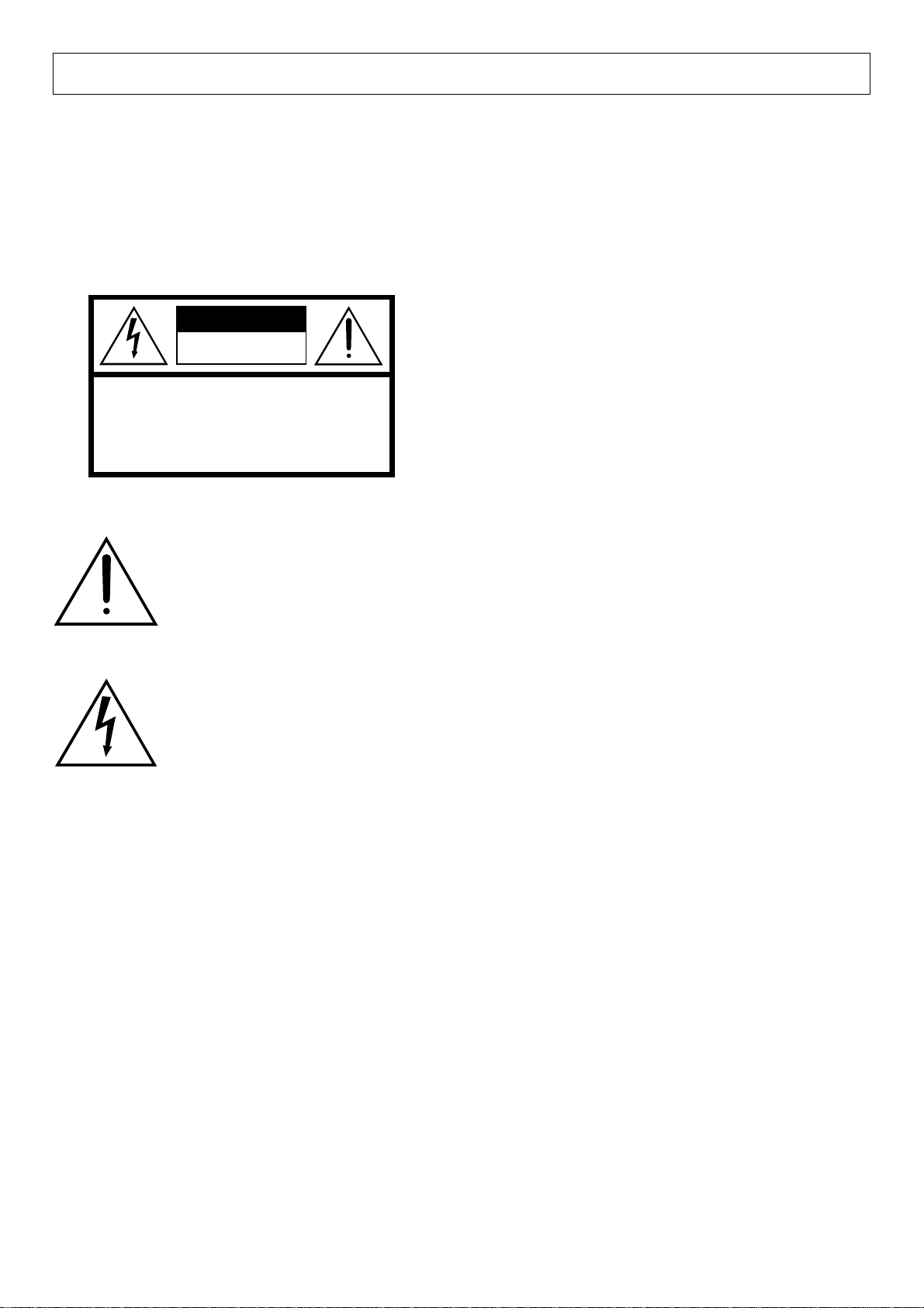
PRODUCT SAFETY MARKINGS: Yamaha electronic
products may have either labels similar to the graphics
shown below or molded/stamped facsimiles of these
graphics on the enclosure. The explanation of these graphics appears on this page. Please observe all cautions indicated on this page and those indicated in the safety instruction section.
CAUTION
RISK OF ELECTRIC SHOCK
DO NOT OPEN
CAUTION: TO REDUCE THE RISK OF ELECTRIC SHOCK.
DO NOT REMOVE COVER (OR BACK).
NO USER-SERVICEABLE PARTS INSIDE.
REFER SERVICING TO QUALIFIED SERVICE PERSONNEL.
See bottom of Keyboard enclosure for graphic symbol markings
The exclamation point with the equilateral triangle is intended to alert the user
to the presence of important operating
and maintenance (servicing) instructions in the literature accompanying the
product.
ENVIRONMENTAL ISSUES: Yamaha strives to produce products that are both user safe and environmentally
friendly. We sincerely believe that our products and the
production methods used to produce them, meet these
goals. In keeping with both the letter and the spirit of the
law, we want you to be aware of the following:
Battery Notice: This product MAY contain a small nonrechargeable battery which (if applicable) is soldered in
place. The average life span of this type of battery is approximately five years. When replacement becomes necessary, contact a qualified service representative to perform
the replacement.
Warning: Do not attempt to recharge, disassemble, or
incinerate this type of battery. Keep all batteries away
from children. Dispose of used batteries promptly and as
regulated by applicable laws. Note: In some areas, the
servicer is required by law to return the defective parts.
However, you do have the option of having the servicer
dispose of these parts for you.
Disposal Notice: Should this product become damaged
beyond repair, or for some reason its useful life is considered to be at an end, please observe all local, state, and
federal regulations that relate to the disposal of products
that contain lead, batteries, plastics, etc.
The lightning flash with arrowhead
symbol within the equilateral triangle is
intended to alert the user to the presence
of uninsulated “dangerous voltage”
within the product’s enclosure that may
be of sufficient magnitude to constitute
a risk of electrical shock.
IMPORTANT NOTICE: All Yamaha electronic products
are tested and approved by an independent safety testing
laboratory in order that you may be sure that when it is
properly installed and used in its normal and customary
manner, all foreseeable risks have been eliminated. DO
NOT modify this unit or commission others to do so unless specifically authorized by Yamaha. Product performance and/or safety standards may be diminished. Claims
filed under the expressed warranty may be denied if the
unit is/has been modified. Implied warranties may also be
affected.
SPECIFICATIONS SUBJECT TO CHANGE: The information contained in this manual is believed to be correct at the time of printing. However, Yamaha reserves the
right to change or modify any of the specifications without
notice or obligation to update existing units.
NOTICE: Service charges incurred due to lack of knowledge relating to how a function or effect works (when the
unit is operating as designed) are not covered by the
manufacturer’s warranty, and are therefore the owners
responsibility. Please study this manual carefully and consult your dealer before requesting service.
NAME PLATE LOCATION: The graphic below indicates the location of the name plate. The model number,
serial number, power requirements, etc., are located on this
plate. You should record the model number, serial number,
and the date of purchase in the spaces provided below and
retain this manual as a permanent record of your purchase.
Model _____________________________________
92-469-q
Serial No.__________________________________
Purchase Date _____________________________
CONTENTS
KEYBOARD STAND ASSEMBLY ......................... 2
THE CONTROLS AND CONNECTORS ................. 4
LISTEN TO THE DEMONSTRATION.................... 6
PLAYING THE PDP-300 ...................................... 6
DUAL M ODE ........................................................ 7
TOUCH SENSITIVITY .......................................... 7
TAKING CARE OF YOUR PDP-300
Your PDP-300 is a fine musical instrument, and deserves the most careful treatment. Observe the following
points and your PDP-300 will sound and look great for
many years.
1. Never open the case and touch or tamper with the in-
ternal circuitry.
2. Always turn the POWER switch OFF after use, and
cover the instrument with the dust cover provided.
3. Clean the cabinet and keys of your PDP-300 only with
a clean, slightly damp cloth. A neutral cleanser may
be used if desired. Never use abrasive cleansers,
waxes, solvents or chemical dust cloths since these
can dull or damage the finish.
4. Never place any vinyl products on your PDP-300.
Contact with vinyl can cause irreversible damage to
the finish.
5. Install your PDP-300 in a place that is away from di-
rect sunlight, excessive humidity or heat.
6. Never apply excessive force to the controls, connec-
tors or other parts of your PDP-300, and avoid
scratching or bumping it with hard objects.
TRANSPOSITION................................................. 7
PITCH CONTROL ................................................. 7
MIDI FUNCTIONS ................................................ 8
MIDI DATA FORMAT ......................................... 11
TROUBLESHOOTING ......................................... 13
SPECIFICATIONS............................................... 13
PREPARATION
• Check your power supply
Make sure that your local AC mains voltage matches
the voltage specified on the name plate on the bottom
panel. Make sure that the voltage selector is set for the
voltage in your area.
• The music stand
If you will be using sheet music with your PDP-300,
raise the music stand built into it’s top panel by lifting
the rear edge of the music stand until it clicks into
place.
The music stand can be lowered after slightly lifting
the stand and pressing the two brackets which support it
inward.
FCC INFORMATION (U.S.A.)
1. IMPORTANT NOTICE: DO NOT MODIFY THIS UNIT!
This product, when installed as indicated in the instructions contained in this manual, meets FCC requirements. Modifications not expressly approved by Yamaha may void your authority, granted by the FCC, to use the product.
2. IMPORTANT: When connecting this product to accessories and/or another product use only high quality shielded cables.
Cable/s supplied with this product MUST be used. Follow all installation instructions. Failure to follow instructions could
void your FCC authorization to use this product in the USA.
3. NOTE: This product has been tested and found to comply with the requirements listed in FCC Regulations, Part 15 for
Class “B” digital devices. Compliance with these requirements provides a reasonable level of assurance that your use of
this product in a residential environment will not result in harmful interference with other electronic devices. This equipment generates/uses radio frequencies and, if not installed and used according to the instructions found in the users
manual, may cause interference harmful to the operation of other electronic devices. Compliance with FCC regulations
does not guarantee that interference will not occur in all installations. If this product is found to be the source of interference, which can be determined by turning the unit “OFF” and “ON”, please try to eliminate the problem by using one of
the following measures:
Relocate either this product or the device that is being affected by the interference.
Utilize power outlets that are on different branch (circuit breaker or fuse) circuits or install AC line filter/s.
In the case of radio or TV interference, relocate/reorient the antenna. If the antenna lead-in is 300 ohm ribbon lead,
change the lead-in to co-axial type cable.
If these corrective measures do not produce satisfactory results, please contact the local retailer authorized to distribute
this type of product. If you can not locate the appropriate retailer, please contact Yamaha Corporation of America, Electronic Service Division, 6600 Orangethorpe Ave, Buena Park, CA90620
The above statements apply ONLY to those products distributed by Yamaha Corporation of America or its subsidiaries.
* This applies only to products distributed by YAMAHA CORPORATION OF AMERICA.
1
1
A
B
C
D
E
Main unit
Center panel
Pedal box
Side panels
Base boards
3
C
D
D
E
E
• Short large-head screws (black)
• Long screws (gold) x 4
4
2
• Short large-head screws (black) x 4
• Long screws (black) x 4
• Short screws (black) x 4
• Joint connectors x 4
• Joint connectors
• The protruding
sections of the
metal brackets
C
B
D
at each end of
the center panel
must face up-
ward.
D
E
• Long screws (black)
KEYBOARD STAND ASSEMBLY
Note: We do not recommend attempting to assemble the PDP-
300 alone. The job can be easily accomplished, however,
with only two people.
D
D
E
E
• Long screws (gold)
2
z
Open the box and remove all the parts.
On opening the box you should find the parts shown in
the illustration to the above. Check to make sure that all
the required parts are provided.
Assemble the side panels (D) and base
x
boards (E).
Install the joint connectors in side panels (D) as shown
in the illustration, then secure the base boards (E) to the
side panels (D) with the long gold-colored screws.
* When installing the joint connectors in the holes in the side
panels (D), make sure that the arrows printed on their upper
surface face in the direction shown in the illustration.
* Make sure that the left and right base boards are facing in the
proper direction as shown in the illustration. The grooved edge
of each base board should face inward.
5
• Short screws (black)
A
A
B
C
D
D
D
E
E
• Insert the screws extending from
the bottom of the main unit into
the bracket grooves.
6
• Cord holders
Attach the side panels (D) to the pedal
c
box (C).
Place the pedal box on top of the brackets attached to
the side panels (D), and attach using the four short largehead black-colored screws.
Attach the center panel (B) to the side
v
panels (D).
The center panel (B) is installed between the side panels (D) with the center lug on each end closer to the
pedal side of the pedal box. Each side of the center panel
is attached using two long black screws.
b
Install the main unit (A).
Place the main unit on the side panels (D) with the
screws on its bottom panel (toward the rear of the main
unit) just behind the grooves in the brackets located at
the top of the side panels (D), then slide the keyboard
forward until it stops.
Align the holes on the bottom panel of the main unit
(A) with the holes in the brackets on the side panels (D),
then screw in and securely tighten the four short blackcolored screws.
7
• Rotate the adjuster unit it coms
in firm contact with the floor
surface.
n
Connect the pedal cords.
Attach the pedal cord to the two pedal cord holders located on the side panel, then insert the pedal cord plug
into the connector located at the bottom of the main
unit’s rear panel, making sure that the tab on the plug
faces forward.
* Check to make sure that all screws have been securely
tightened.
m
Be sure to set the adjuster.
For stability, an adjuster is provided on the bottom of
the pedal box (C). Rotate the adjuster until it comes in
firm contact with the floor surface. The adjuster ensures
stable pedal operation and facilitates pedal effect control.
* If the adjuster is not in firm contact with the floor surface,
distorted sound may result.
3
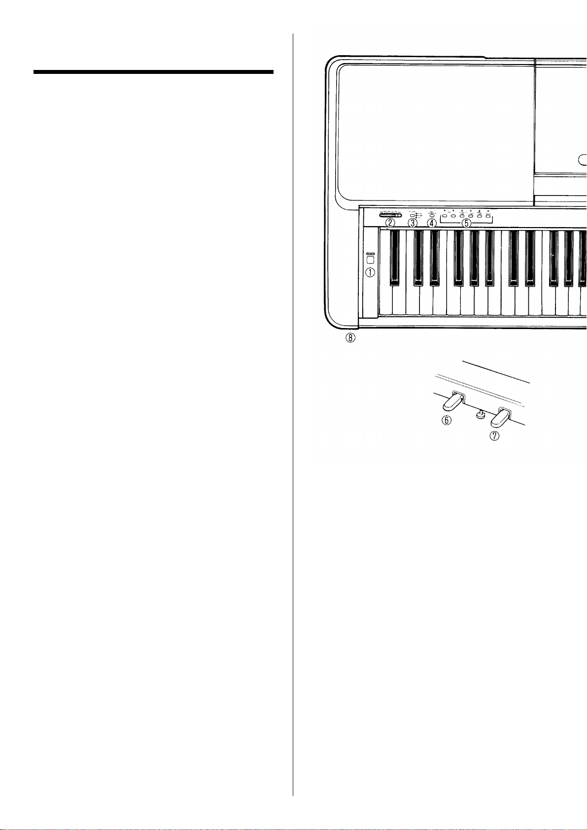
THE CONTROLS AND
CONNECTORS
q [POWER] Switch
Press the [POWER] switch once to turn the power
ON, a second time to turn the power OFF. When the
power is initially turned ON, the PIANO 1 voice selector LED will light.
w [MASTER VOLUME] Control
The [MASTER VOLUME] control adjusts the volume (level) of sound produced by the PDP-300. The
[MASTER VOLUME] control also adjusts headphone
volume when a pair of headphones is plugged into the
HEADPHONE jack i.
e [REVERB] Button
The [REVERB] button selects a number of digital
effects that you can use for extra depth and expressive power.
To select an effect press the [REVERB] button a
few times until the indicator corresponding to the desired effect lights (the indicators light in sequence
each time the [REVERB] button is pressed). No effect is produced when all indicators are off.
PEDAL
When the PEDAL indicator is lit, a subtle but warm
reverb effect is added to the sound whenever the
damper pedal is pressed.
ROOM
This setting add a continuous reverb effect to the
sound that is similar to the type of acoustic reverberation you would hear in a medium-size room.
HALL
For a really spacious reverb sound, use the HALL
setting. This effect simulates the natural reverberation of a large concert hall.
Note: When the [POWER] switch is initially turned ON all
reverb effects are turned OFF.
r [MIDI/TRANSPOSE] Button
The [MIDI/TRANSPOSE] button allows access to
the PDP-300’s TRANSPOSE function (to shift the
pitch of the entire keyboard up or down) and MIDI
functions. For details refer to the “TRANSPOSITION” and “MIDI FUNCTIONS” sections on pages 7
and 8, respectively.
t Voice Selectors
The PDP-300 has six voice selectors. Simply press
any of the voice selectors to select the corresponding
voice. The LED indicator above the voice selector
will light to indicate which voice is currently selected.
The PDP-300 also has a DUAL mode in which two
voices can be played simultaneously across the full
range of the keyboard — see page 7 for details.
Note: The PIANO 1 voice is automatically selected
whenever the [POWER] switch is initially turned ON.
y Soft/Sostenuto Pedal
This pedal has two distinct modes — “soft” and
“sostenuto” — which can be selected as required.
The Soft Mode
This is the normal mode for the Soft/Sostenuto
pedal, and is automatically selected when the power
is initially turned ON.
In this mode, pressing the pedal reduces the volume and slightly changes the timbre of notes
played.
The Sostenuto Mode
From the normal Soft mode, the Sostenuto mode
can be selected by holding down the [MIDI/
TRANSPOSE] button r and pressing the Soft/
Sostenuto pedal once.
In the sostenuto mode, if you play a note or
chord on the keyboard and press the pedal while the
note(s) are held, those notes will be sustained as
long as the pedal is held (as if the damper pedal had
been pressed) but all subsequently played notes will
not be sustained. This makes it possible to sustain a
chord, for example, while other notes are played
“staccato.”
From the Sostenuto mode it is possible to return
to the Soft pedal mode by holding down the [MIDI/
TRANSPOSE] button and pressing the Soft/Sostenuto pedal.
4
 Loading...