

Yamaha Audio PDM-1 User Manual
R
PDM-1
HIGH DEFINITION
INPUT
INPUT
SURROUND
SURROUND
VOL
VOL
NR
NR
PICTURE
SET UP
PICTURE
SET UP
SOUND
SOUND
PICTURE
PICTURE
POS. /SIZE
POS. /SIZE
ASPECT
ASPECT
OFF TIMER
OFF TIMER
PC
PC
+
OL
V
–
UT
INP
Y
ANDB
/
R
R - ST
E
OW
P
WER ON
G PO
PLASMA MONITOR
English
Operating Instructions
TQZW251

2

Table of Contents
Important Safety Notice..............................................4
Safety Precautions......................................................5
Accessories .................................................................7
Accessories Supply....................................................7
Optional Accessories .................................................7
Remote Control Batteries...........................................8
Connections ................................................................9
Basic connection......................................................10
Speaker Terminals connection................................. 11
Component/RGB Input connection ..........................12
PC Input Terminals connection ................................13
SERIAL Terminals connection..................................15
Basic Controls...........................................................16
Power On/Off and input signal selection ................18
AC cord connection..................................................18
Power On/Off ...........................................................18
Select the input signal..............................................19
Selecting the On-Screen Menu Language...............19
On-Screen Menu Display from Remote Control.....20
ASPECT Controls......................................................22
Adjusting Picture Pos./Size .....................................24
Sound Adjustment ....................................................26
Mute .........................................................................26
Surround Controls ....................................................27
Picture Adjustments .................................................28
Advanced settings....................................................29
Set up TIMER .............................................................30
PRESENT TIME Set ................................................30
TIMER Set ...............................................................31
Screensaver (For preventing after-images)............32
Setup of Screensaver Time......................................33
Side Panel Adjustment.............................................33
Setup for Input Signals.............................................34
Component/RGB-in select .......................................34
3D Y/C Filter – For NTSC AV images ......................34
Colour system / Aspect Auto ....................................35
3:2 Pulldown ............................................................35
Sync .........................................................................36
H-Freq. (kHz)/V-Freq. (Hz).......................................36
Troubleshooting........................................................37
Specifications............................................................38
3
Important Safety Notice
WARNING: To prevent damage which may result in fire or shock hazard, do not expose this appliance to
rain or moisture.
Do not place containers with water (flower vase, cups, cosmetics, etc.) above the set.
(including on shelves above, etc.)
WARNING: 1) To prevent electric shock, do not remove cover. No user serviceable parts inside. Refer servicing
to qualified service personnel.
2) Do not remove the earthing pin on the power plug. This apparatus is equipped with a three pin
earthing-type power plug. This plug will only fit an earthing-type power outlet. This is a safety
feature. If you are unable to insert the plug into the outlet, contact an electrician.
Do not defeat the purpose of the earthing plug.
WARNING
This is a class A product. In a domestic environment this product may cause radio interference in which case you
may be required to take adequate measures.
CAUTION
This appliance is intended for use in environments which are relatively free of electromagnetic fields.
Using this appliance near sources of strong electromagnetic fields or where electrical noise may overlap with the
input signals could cause the picture and sound to wobble or cause interference such as noise to appear.
To avoid the possibility of harm to this appliance, keep it away from sources of strong electromagnetic fields.
To prevent electric shock, ensure the grounding pin on the AC cord power plug is securely connected.
Trademark Credits
VGA is a trademark of International Business Machines Corporation.
•
Macintosh is a registered trademark of Apple Computer, USA.
•
S-VGA is a registered trademark of the Video Electronics Standard Association.
•
Even if no special notation has been made of company or product trademarks, these trademarks have been
fully respected.
Note:
Do not allow a still picture to be displayed for an extended period, as this can cause a permanent after-image to remain
on the plasma display.
Examples of still pictures include logos, video games, computer images, teletext and images displayed in 4:3 mode.
4

Safety Precautions
WARNING
Setup
This plasma display is for use only with the following optional accessories. Use with any other type of optional
accessories may cause instability which could result in the possibility of injury.
Pedestal
•
Wall Mounting Unit
•
Speakers
•
(In the case of connecting the speakers directly with the speaker terminals of the plasma display)
Always be sure to ask a qualified technician to carry out set-up.
Do not place the plasma display on sloped or unstable surfaces.
The plasma display may fall off or tip over.
•
Do not place any objects on top of the plasma display.
If water is spills onto the plasma display or foreign objects get inside it, a short-circuit may occur which could result
•
in fire or electric shock. If any foreign objects get inside the plasma display, please consult your local Yamaha
dealer.
If using the pedestal (optional accessory), leave a space of at least 10 cm at the top, left and right, at least 6 cm
at the bottom, and at least 7 cm at the rear. If using some other setting-up method, leave a space of at least
10 cm at the top, bottom, left and right, and at least 1.9 cm at the rear.
..........................................
..........................
.........................................
PDS-150
PWK-150
SP-PDM1
Avoid installing this product near electronic equipment that is easy to receive electromagnetic waves.
It may cause interference in image, sound, etc. In particular, keep video equipment away from this product.
•
When using the plasma display
The plasma display is designed to operate on 220 - 240 V AC, 50/60 Hz.
Do not cover the ventilation holes.
Doing so may cause the plasma display overheat, which can cause fire or damage to the plasma display.
•
Do not stick any foreign objects into the plasma display.
Do not insert any metal or flammable objects into the ventilations holes or drop them onto the plasma display, as
•
doing so can cause fire or electric shock.
Do not remove the cover or modify it in any way.
High voltages which can cause severe electric shocks are present inside the plasma display. For any inspection,
•
adjustment and repair work, please contact your local Yamaha dealer.
Securely insert the power cord plug as far as it will go.
If the plug is not fully inserted, heat may be generated which could cause fire. If the plug is damaged or the wall
•
socket plate is loose, they shall not be used.
Do not handle the power cord plug with wet hands.
Doing so may cause electric shocks.
•
Do not do anything that may damage the power cable. When disconnecting the power cable, pull on the plug
body, not the cable.
Do not damage the cable, make any modifications to it, place heavy objects on top of it, heat it, place it near any
•
hot objects, twist it, bend it excessively or pull it. To do so may cause fire and electric shock. If the power cable is
damaged, have it repaired at your local Yamaha dealer.
If the plasma display is not going to be used for any prolonged length of time, unplug the power cord plug
from the wall outlet.
5

Safety Precautions
If problems occur during use
If a problem occurs (such as no picture or no sound), or if smoke or an abnormal odour starts to come out
from the plasma display, immediately unplug the power cord plug from the wall outlet.
If you continue to use the plasma display in this condition, fire or electric shock could result. After checking that the
•
smoke has stopped, contact your local Yamaha dealer so that the necessary repairs can be made. Repairing the
plasma display yourself is extremely dangerous, and shall never be done.
If water or foreign objects get inside the plasma display, if the plasma display is dropped, or if the cabinet
becomes damages, disconnect the power cord plug immediately.
A short circuit may occur, which could cause fire. Contact your local Yamaha dealer for any repairs that need to be
•
made.
CAUTION
When using the plasma display
Do not bring your hands, face or objects close to the ventilation holes of the plasma display.
Heated air comes out from the ventilation holes at the top of plasma display will be hot. Do not bring your hands or
•
face, or objects which cannot withstand heat, close to this port, otherwise burns or deformation could result.
Be sure to disconnect all cables before moving the plasma display.
If the plasma display is moved while some of the cables are still connected, the cables may become damaged, and
•
fire or electric shock could result.
Disconnect the power cord plug from the wall socket as a safety precaution before carrying out any cleaning.
Electric shocks can result if this is not done.
•
Clean the power cable regularly to prevent it becoming dusty.
If dust built up on the power cord plug, the resultant humidity can damage the insulation, which could result in fire.
•
Pull the power cord plug out from the wall outlet and wipe the mains lead with a dry cloth.
This Plasma Display radiates infrared rays, therefore it may affect other infrared communication equipment.
Install your infrared sensor in a place away from direct or reflected light from your Plasma Display.
Cleaning and maintenance
The front of the display panel has been specially treated. Wipe the panel surface gently using only a cleaning
cloth or a soft, lint-free cloth.
If the surface is particularly dirty, wipe with a soft, lint-free cloth which has been soaked in pure water or water to
•
which a small amount of neutral detergent has been added, and then wipe it evenly with a dry cloth of the same
type until the surface is dry.
Do not scratch or hit the surface of the panel with fingernails or other hard objects, otherwise the surface may
•
become damaged. Furthermore, avoid contact with volatile substances such as insect sprays, solvents and thinner,
otherwise the quality of the surface may be adversely affected.
If the cabinet becomes dirty, wipe it with a soft, dry cloth.
If the cabinet is particularly dirty, soak the cloth in water to which a small amount of neutral detergent has been
•
added and then wring the cloth dry. Use this cloth to wipe the cabinet, and then wipe it dry with a dry cloth.
Do not allow any detergent to come into direct contact with the surface of the plasma display.
•
If water droplets get inside the unit, operating problems may result.
Avoid contact with volatile substances such as insect sprays, solvents and thinner, otherwise the quality of the
•
cabinet surface may be adversely affected or the coating may peel off. Furthermore, do not leave it for long periods
in contact with articles made from rubber or PVC.
6
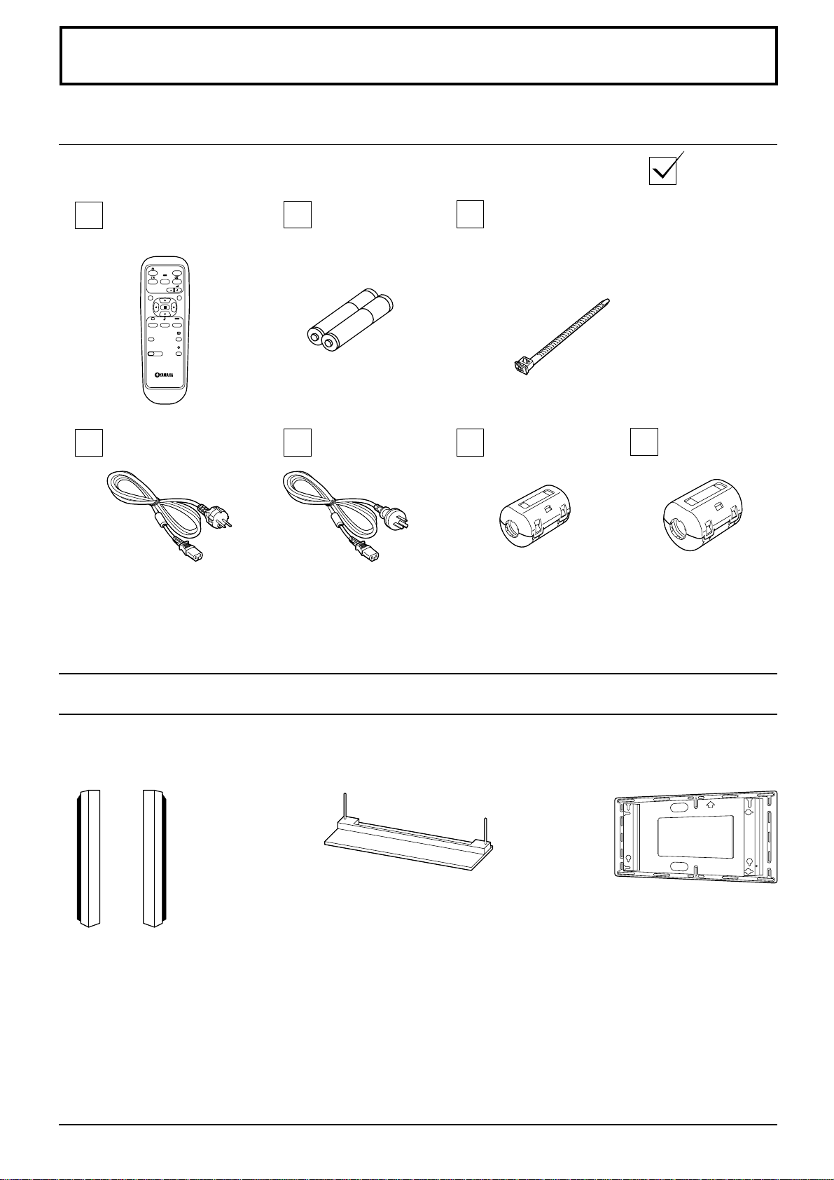
Accessories
Accessories Supply
Check that you have the accessories and items shown
Remote Control
Transmitter
INPUT
SURROUND
VOL
NR
PICTURE
SET UP
SOUND
PICTURE
POS. /SIZE
ASPECT
OFF TIMER
PC
AC cord
Batteries for the
Remote Control
Transmitter
(2 × R6 Size)
AC cord
(Australia)
Fixing bands
2 pcs
Ferrite core
(small size) × 1
Ferrite core
(large size) × 2
Optional Accessories
Speakers
•
SP-PDM1
(Special order products)
For assembling
Full instructions are supplied with each optional accessory for use with this plasma display.
Pedestal
•
PDS-150
•
Wall Mounting Unit
PWK-150
7
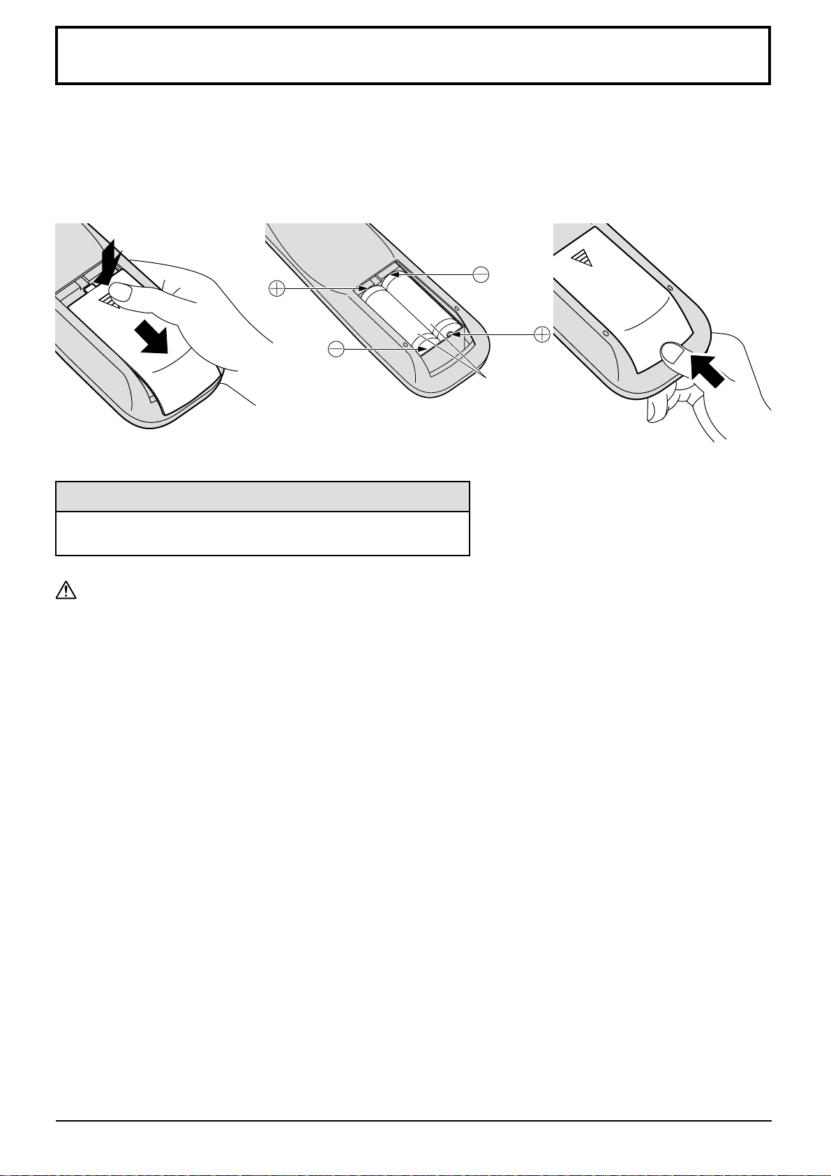
Remote Control Batteries
Requires two R6 batteries.
1. Turn the transmitter face down.
Press and slide off the battery
cover.
2. Install the batteries as shown in
the battery compartment.
(Polarity + or – must match the
markings in the compartment.)
3. Replace the cover and slide in
reverse until the lock snaps.
Two "R6" size
Helpful Hint:
For frequent remote control users, replace old batteries with
Alkaline batteries for longer life.
Precaution on battery use
Incorrect installation can cause battery leakage and corrosion that will damage the remote control transmitter.
Observe the following precaution:
1. Batteries shall always be replaced as a pair. Always use new batteries when replacing the old set.
2. Do not combine a used battery with a new one.
3. Do not mix battery types (example: “Zinc Carbon” with “Alkaline”).
4. Do not attempt to charge, short-circuit, disassemble, heat or burn used batteries.
5. Battery replacement is necessary when remote control acts sporadically or stops operating the plasma display
set.
8
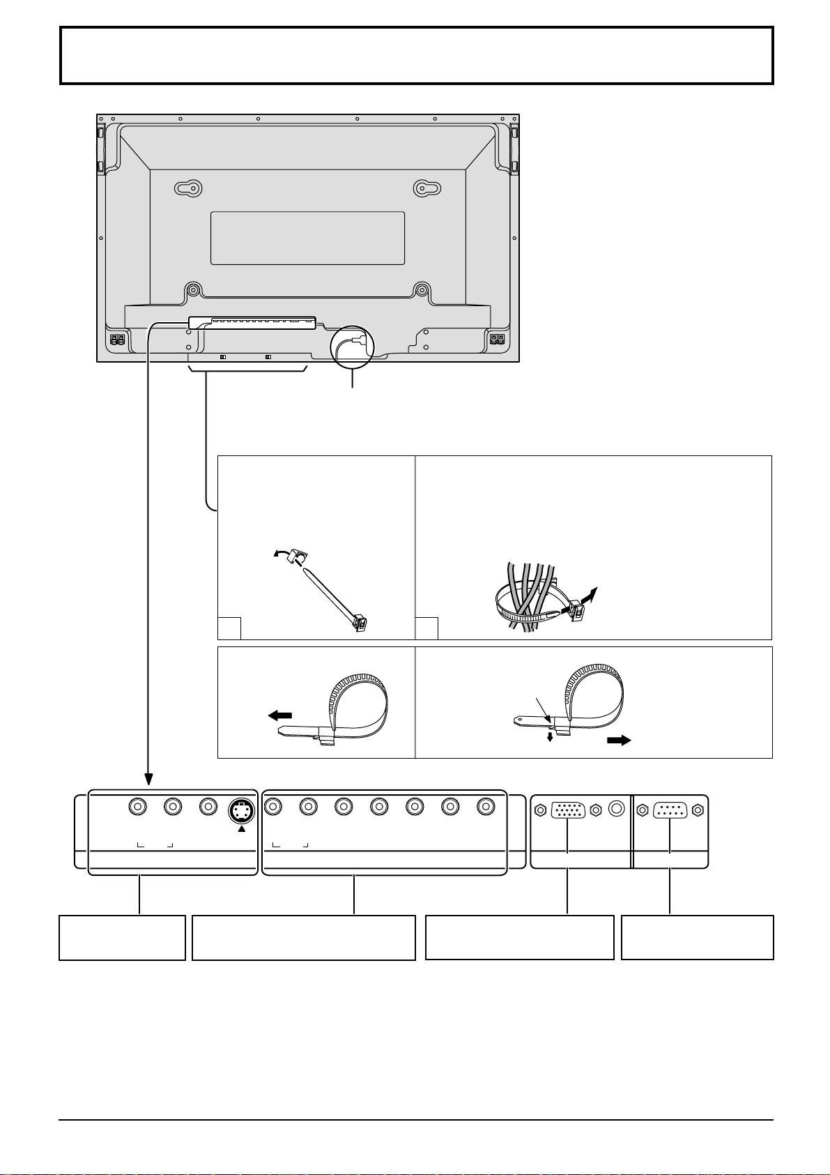
Connections
– Cable fixing bands
Secure any excess cables with bands, as required.
AC cord connection (see page 18)
Pass the attached cable
fixing band through the clip
as shown in the figure.
T o secure cables connected to Terminals, wrap the cable
fixing band around them then pass the pointed end
through the locking block, as shown in the figure.
While ensuring there is sufficient slack in cables to
minimize stress (especially in the power cord), firmly
bind all cables with the supplied fixing band.
1 2
To tighten:
Pull
L
L
R
AUDIO
S VIDEOVIDEO
R
AUDIO
HD
VD
COMPONENT/RGB INAV IN
PR/CR/R
To loosen:
Push
the catch
Pull
AUDIO
PB/CB/B Y/G
PC IN SERIAL
AV IN Terminals
(see page 10, 11)
COMPONENT/RGB IN and Audio IN
Terminals (see page 10, 11, 12)
From EXIT monitor Terminal
on Computer (see page 13)
From SERIAL Terminal on
Computer (see page 15)
9
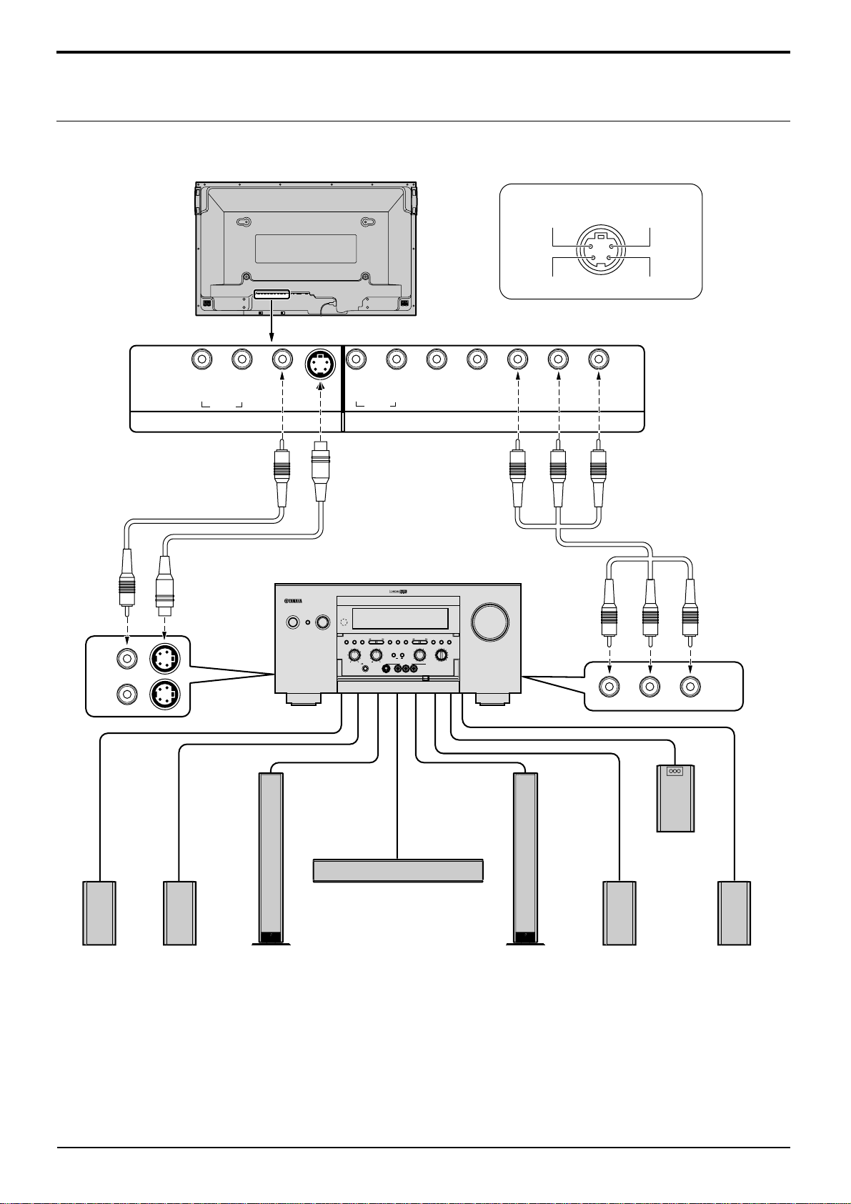
Connections
Basic connection
(Example) When connecting an AV amplifier
S VIDEO 4 pin socket
Luminance earth
Chrominance earth
Video pin cable
VIDEO
1
MONITOR
OUT
2
R
AUDIO
S VIDEO
Luminance in
L
L
VIDEO
S VIDEO
R
AUDIO
HD
VD
PR/CR/R
P
B/CB/B Y/G
Chrominance in
COMPONENT/RGB INAV IN
S Video cable
Component
Video cable
AV amplifier
INPUT SELECTOR
INPUT MODE
STANDBY
/ON
6CH
SPEAKERS
STEREO
PROGRAM
INPUT
A B
BASS
TREBLE
SILENT
PHONES
S VIDEO VIDEO
PRESET
PRESET
MEMORY
/TUNING
/TUNING
FM/AM
A/B/C/D/E
EDIT
EFFECT
PROCESSOR
DIRECT
ON
MAN'L/AUTO FM
SOURCE/REMOTE
BALANCE
D–TV/LD
CABLE
BASS
EXTENSION
SAT
VCR 1
VCR 2
OFF
LR
VIDEO AUX
VCR 3/DVR
VIDEO AUX
REC OUT/ZONE 2
LAUDIO
R
OPTICAL
VOLUME
TUNING
MODE
AUTO/MAN'L MONO
DVD
MD/TAPE
CD–R
TUNER
CD
PHONO
COMPONENT
VIDEO
MONITOR
OUT
Front effect
speaker
Rear
speaker
Main
speaker
Notes:
(1) Change the “Component/RGB-in” setting in the “Setup” menu to “Component”. (see page 34)
(2) Any equipment and cables other than the display illustrated above are not included.
Choose one connecting cable from Video, S Video or Component Video, that is suitable for the equipment being used.
(3)
(4) Generally the quality of images obtained varies between connection methods in the descending order of Component
Video, S Video and Video.
10
Center speaker
Main
speaker
Rear
speaker
Subwoofer
Front effect
speaker
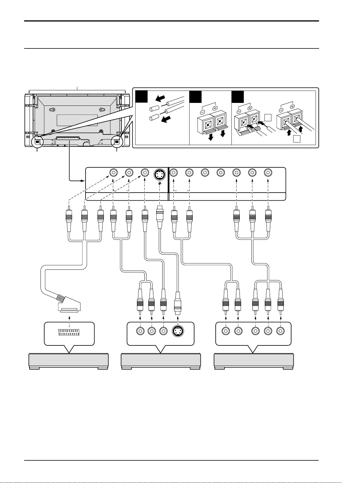
Connections
Speaker Terminals connection
When you do not use an AV amplifier, connect the speakers directly with the speaker terminals of the plasma display.
Refer to the speaker’s Installation Manual for details on speaker installation.
When connecting the speakers, be sure to use only the optional accessory speakers.
Speakers (Optional accessories)
SPEAKERS
Terminals (R)
21pin scart cable
1
Remove the tubes
from the ends of
the speaker cables.
SPEAKERS
Terminals (L)
RL
AUDIO
Video pin cable
Audio pin cable
2
3
1
2
S VIDEOVIDEO
RL
AUDIO
COMPONENT/RGB INAV IN
Audio pin cable
S Video
cable
HD
VD
PR/CR/R
B/CB
P
/B Y/G
Component
Video cable
TV OUT
(DVD Player) (DVD Player) (DVD Player)
VIDEO signal connection
VIDEO or S VIDEO signal connection Component signals (Y, PB, PR) connection
with 21pin scart cable
Notes:
(1) Change the “Component/RGB-in” setting in the “Setup” menu to “Component”. (see page 34)
(2) Any equipment and cables other than the display illustrated above are not included.
(3)
Choose one connecting cable from Video, S Video or Component Video, that is suitable for the equipment being used.
(4) Generally the quality of images obtained varies between connection methods in the descending order of Component
Video, S Video and Video.
(5) When utilizing the R/G/B/Video signals from the TV OUT(SCART) terminal of a DVD player or similar, use a 4-pin
cable to connect signals to the appropriate input terminal of the display.
Audio
OUT
RL
Video
OUT
S Video
OUT
Audio
OUT
LR
Component Video OUT
BPR
YP
11
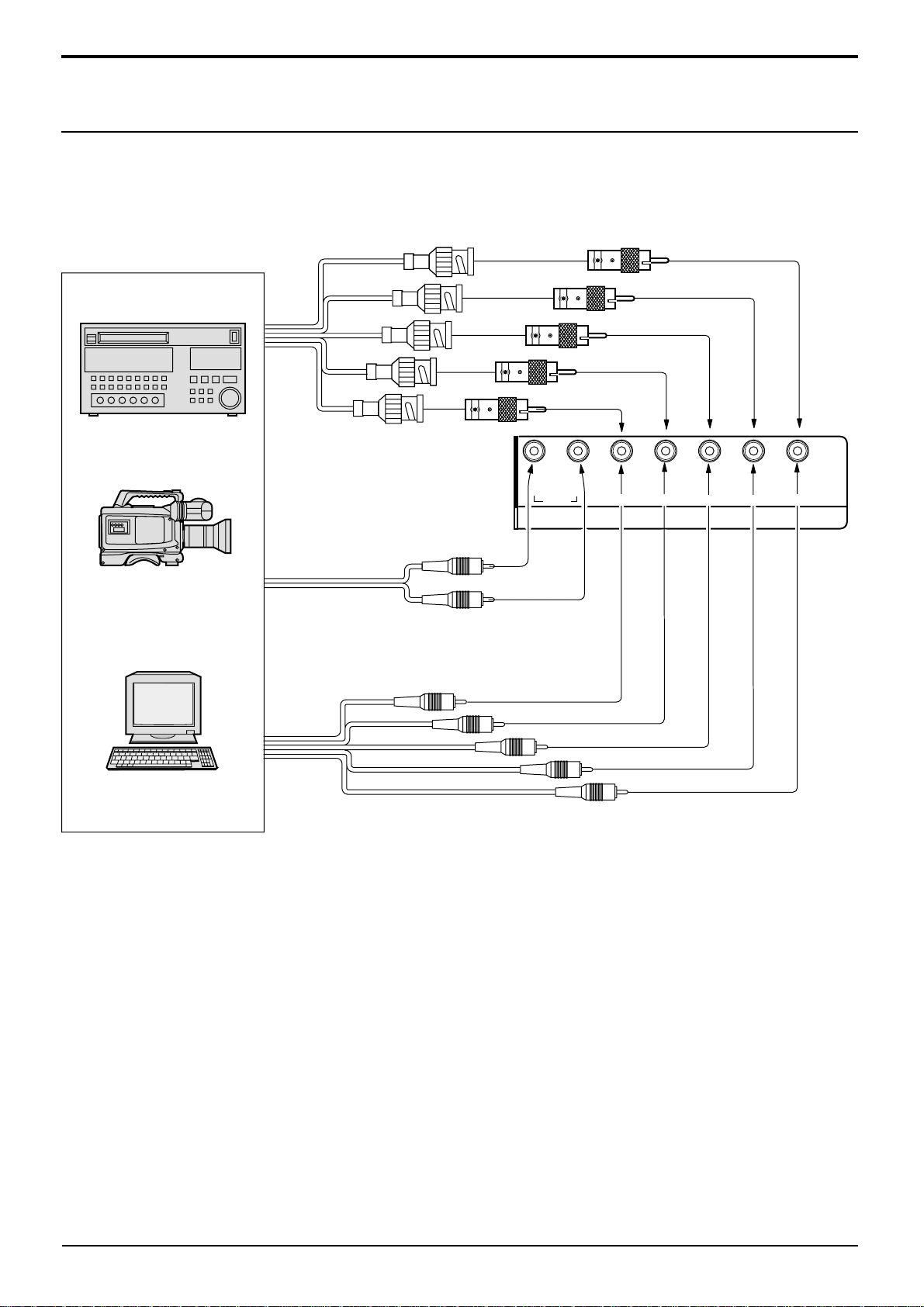
Connections
Component/RGB Input connection
RGB signal (R, G, B, HD, VD) connection
Example of input signal source
HDTV-compatible VCR
RGB camera
Computer
RGB input to
R, G, B, HD, VD sockets
5×BNC
RGB cables
AUDIO
2×RCA
audio cables
Audio input to
L/R sockets
BNC-RCA
adaptor plug
R L
AUDIO
P
R/CR
HD
VD
COMPONENT/RGB IN
/R
B/CB
/B
P
Y/G
VD
HD
R
B
G
Notes:
(1) Change the “Component/RGB-in” setting in the “Setup” menu to “RGB”. (see page 34)
(2) Any equipment and cables other than the display illustrated above are not included.
Choose one connecting cable from Video, S Video or Component Video, that is suitable for the equipment being used.
(3)
(4) Generally the quality of images obtained varies between connection methods in the descending order of Component
Video, S Video and Video.
12
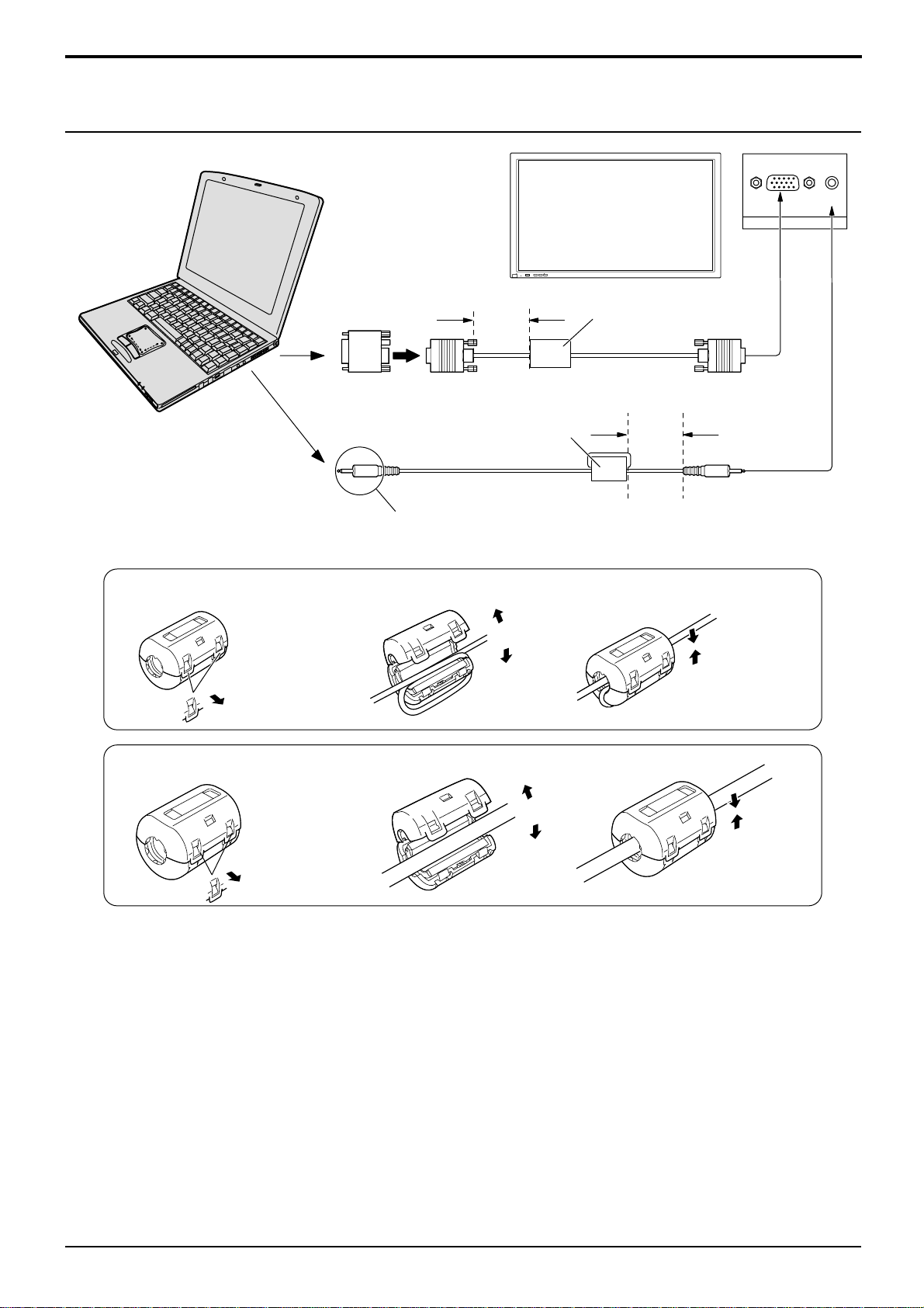
PC Input Terminals connection
COMPUTER
POWER /
R - STANDBY
G POWER ON
Conversion adapter
(if necessary)
Less than
15
3"
/
16
(10 cm)
Ferrite core (small size)
Audio
INPUT
—
VOL
+
(supplied)
Connections
Ferrite core (large size)
(supplied)
RGB
PC cable
Less than
3"
(10 cm)
15
/
16
D-sub 15p
AUDIO
PC IN
Installing the ferrite core (Small size)
1
2
Pull back the tabs
(in two places)
Installing the ferrite core (Large size)
1
2
Pull back the tabs
(in two places)
Connect a cable which matches
the audio output terminal on the computer.
3
Open
3
Open
1/8" (3 mm)
Stereo plug
Press the cable
through and close
Press the cable
through and close
Notes:
(1) Computer signals which can be input are those with a horizontal scanning frequency of 15.6 to 1 10 kHz and vertical
scanning frequency of 48 to 120 Hz. (However, the image will not be displayed properly if the signals exceed 1,200
lines.)
(2) The display resolution is a maximum 1,024 × 768 dots when the aspect mode is set to “4:3”, and 1,366 × 768 dots
when the aspect mode is set to “16:9”. If the display resolution exceeds these maximums, it may not be possible to
show fine detail with sufficient clarity.
(3) The PC input terminals are DDC1/2B-compatible. If the computer being connected is not DDC1/2B-compatible,
you will need to make setting changes to the computer at the time of connection.
(4) Some PC models cannot be connected to the set.
(5) There is no need to use an adapter for computers with DOS/V compatible D-sub 15P terminal.
(6) The computer shown in the illustration is for example purposes only.
(7) Additional equipment and cables shown are not supplied with this set.
(8) Do not set the horizontal and vertical scanning frequencies for PC signals which are above or below the specified
frequency range.
13
 Loading...