

Yamaha Audio MX400 User Manual
MIXING CONSOLE
CONSOLES DE MIXAGE
MISCHPULTE
CONSOLA DE MEZCLA
User’s Guide
Manuel d’utilisation
Bedienungsanleitung
Manual de uso
20dB
–16 –60
SIGNAL
–15 +15
250
MID FREQ
–15 +15
–15 +15
EQ
010
010
010
010
PRE
010
1–2
3–4
L
ODD
ON
PFL
1
A
B
GAIN
PEAK
80
HIGH
5K
MID
LOW
P
AUX 1
R
E
AUX 2
AUX 3
AUX 4
P
O
S
T
AUX 5
ST
R
EVEN
PAN
10
5
0
5
10
15
20
25
30
40
∞
1
20dB
–16 –60
SIGNAL
–15 +15
250
MID FREQ
–15 +15
–15 +15
EQ
010
010
010
010
PRE
010
1–2
3–4
L
ODD
ON
PFL
A
A
A
B
B
B
20dB
20dB
–16 –60
–16 –60
GAIN
GAIN
GAIN
PEAK
PEAK
PEAK
SIGNAL
SIGNAL
80
80
80
–15 +15
–15 +15
HIGH
HIGH
HIGH
250
5K
250
5K
5K
MID FREQ
MID FREQ
–15 +15
–15 +15
MID
MID
MID
–15 +15
–15 +15
LOW
LOW
LOW
EQ
EQ
010
010
P
P
P
AUX 1
AUX 1
AUX 1
R
R
R
E
E
E
010
010
AUX 2
AUX 2
AUX 2
010
010
AUX 3
AUX 3
AUX 3
010
010
AUX 4
AUX 4
AUX 4
PRE
PRE
P
P
P
O
O
O
S
S
S
T
T
T
010
010
AUX 5
AUX 5
AUX 5
1–2
1–2
3–4
3–4
ST
ST
ST
R
R
R
L
L
EVEN
EVEN
EVEN
ODD
ODD
PAN
PAN
PAN
ON
ON
PFL
PFL
10
10
10
5
5
5
0
0
0
5
5
5
10
10
10
15
15
15
20
20
20
25
25
25
30
30
30
40
40
40
∞
∞
∞
4
3
2
20dB
–16 –60
SIGNAL
–15 +15
250
MID FREQ
–15 +15
–15 +15
EQ
010
010
010
010
PRE
010
1–2
3–4
L
ODD
ON
PFL
A
A
A
B
B
B
20dB
20dB
–16 –60
–16 –60
GAIN
GAIN
GAIN
PEAK
PEAK
PEAK
SIGNAL
SIGNAL
80
80
80
–15 +15
–15 +15
HIGH
HIGH
HIGH
250
5K
250
5K
5K
MID FREQ
MID FREQ
–15 +15
–15 +15
MID
MID
MID
–15 +15
–15 +15
LOW
LOW
LOW
EQ
EQ
010
010
P
P
P
AUX 1
AUX 1
AUX 1
R
R
R
E
E
E
010
010
AUX 2
AUX 2
AUX 2
010
010
AUX 3
AUX 3
AUX 3
010
010
AUX 4
AUX 4
AUX 4
PRE
PRE
P
P
P
O
O
O
S
S
S
T
T
T
010
010
AUX 5
AUX 5
AUX 5
1–2
1–2
3–4
3–4
ST
ST
ST
R
R
R
L
L
EVEN
EVEN
EVEN
ODD
ODD
PAN
PAN
PAN
ON
ON
PFL
PFL
10
10
10
5
5
5
0
0
0
5
5
5
10
10
10
15
15
15
20
20
20
25
25
25
30
30
30
40
40
40
∞
∞
∞
7
6
5
20dB
–16 –60
SIGNAL
–15 +15
250
MID FREQ
–15 +15
–15 +15
EQ
010
010
010
010
PRE
010
1–2
3–4
L
ODD
ON
PFL
A
A
A
B
B
B
20dB
20dB
–16 –60
–16 –60
GAIN
GAIN
GAIN
PEAK
PEAK
PEAK
SIGNAL
SIGNAL
80
80
80
–15 +15
–15 +15
HIGH
HIGH
HIGH
250
5K
250
5K
5K
MID FREQ
MID FREQ
–15 +15
–15 +15
MID
MID
MID
–15 +15
–15 +15
LOW
LOW
LOW
EQ
EQ
010
010
P
P
AUX 1
AUX 1
AUX 1
R
R
E
E
010
010
AUX 2
AUX 2
AUX 2
010
010
AUX 3
AUX 3
AUX 3
010
010
AUX 4
AUX 4
AUX 4
PRE
PRE
P
P
O
O
S
S
T
T
010
010
AUX 5
AUX 5
AUX 5
1–2
1–2
3–4
3–4
ST
ST
ST
R
R
L
L
EVEN
EVEN
EVEN
ODD
ODD
PAN
PAN
PAN
ON
ON
PFL
PFL
10
10
5
5
0
0
5
5
10
10
15
15
20
20
25
25
30
30
40
40
∞
∞
10
9
8
10
9
8
7
6
5
4
3
2
11
A
A
A
B
B
B
20dB
20dB
20dB
–16 –60
–16 –60
–16 –60
GAIN
GAIN
GAIN
PEAK
PEAK
PEAK
SIGNAL
SIGNAL
SIGNAL
80
80
80
–15 +15
–15 +15
–15 +15
HIGH
HIGH
HIGH
250
5K
250
5K
250
5K
MID FREQ
MID FREQ
MID FREQ
–15 +15
–15 +15
–15 +15
MID
MID
MID
–15 +15
–15 +15
–15 +15
LOW
LOW
LOW
EQ
EQ
EQ
010
010
010
P
AUX 1
R
E
010
AUX 2
010
AUX 3
010
AUX 4
PRE
P
O
S
T
010
AUX 5
1–2
3–4
ST
R
L
ODD
PAN
ON
PFL
10
5
0
5
10
15
20
25
30
40
∞
P
P
P
AUX 1
AUX 1
R
R
R
E
E
E
010
010
AUX 2
AUX 2
010
010
AUX 3
AUX 3
010
010
AUX 4
AUX 4
PRE
PRE
P
P
P
O
O
O
S
S
S
T
T
T
010
010
AUX 5
AUX 5
1–2
1–2
3–4
3–4
ST
ST
R
R
R
L
L
EVEN
EVEN
EVEN
ODD
ODD
PAN
PAN
ON
ON
PFL
PFL
10
10
10
5
5
5
0
0
0
5
5
5
10
10
10
15
15
15
20
20
20
25
25
25
30
30
30
40
40
40
∞
∞
∞
13
12
11
20dB
–16 –60
SIGNAL
–15 +15
250
MID FREQ
–15 +15
–15 +15
EQ
010
010
010
010
PRE
010
1–2
3–4
L
ODD
ON
PFL
A
A
A
B
B
B
20dB
20dB
–16 –60
–16 –60
GAIN
GAIN
GAIN
PEAK
PEAK
PEAK
SIGNAL
SIGNAL
80
80
80
–15 +15
–15 +15
HIGH
HIGH
HIGH
250
5K
250
5K
5K
MID FREQ
MID FREQ
–15 +15
–15 +15
MID
MID
MID
–15 +15
–15 +15
LOW
LOW
LOW
EQ
EQ
010
010
P
P
P
AUX 1
AUX 1
AUX 1
AUX 2
AUX 3
AUX 4
AUX 5
ST
PAN
R
R
R
E
E
E
010
010
AUX 2
AUX 2
010
010
AUX 3
AUX 3
010
010
AUX 4
AUX 4
PRE
PRE
P
P
P
O
O
O
S
S
S
T
T
T
010
010
AUX 5
AUX 5
1–2
1–2
3–4
3–4
ST
ST
R
R
R
L
L
EVEN
EVEN
EVEN
ODD
ODD
PAN
PAN
ON
ON
PFL
PFL
10
10
10
5
5
5
0
0
0
5
5
5
10
10
10
15
15
15
20
20
20
25
25
25
30
30
30
40
40
40
∞
∞
∞
16
15
14
20dB
–16 –60
SIGNAL
–15 +15
250
MID FREQ
–15 +15
–15 +15
EQ
010
010
010
010
PRE
010
1–2
3–4
L
ODD
ON
PFL
A
A
A
B
B
B
20dB
20dB
–16 –60
–16 –60
GAIN
GAIN
GAIN
PEAK
PEAK
PEAK
SIGNAL
SIGNAL
80
80
80
–15 +15
–15 +15
HIGH
HIGH
HIGH
250
5K
250
5K
5K
MID FREQ
MID FREQ
–15 +15
–15 +15
MID
MID
MID
–15 +15
–15 +15
LOW
LOW
LOW
EQ
EQ
010
010
P
P
P
AUX 1
AUX 1
AUX 1
AUX 2
AUX 3
AUX 4
AUX 5
ST
PAN
R
R
R
E
E
E
010
010
AUX 2
AUX 2
010
010
AUX 3
AUX 3
010
010
AUX 4
AUX 4
PRE
PRE
P
P
P
O
O
O
S
S
S
T
T
T
010
010
AUX 5
AUX 5
1–2
1–2
3–4
3–4
ST
ST
R
R
R
L
L
EVEN
EVEN
EVEN
ODD
ODD
PAN
PAN
ON
ON
PFL
PFL
10
10
10
5
5
5
0
0
0
5
5
5
10
10
10
15
15
15
20
20
20
25
25
25
30
30
30
40
40
40
∞
∞
∞
20dB
–16 –60
SIGNAL
–15 +15
250
MID FREQ
–15 +15
–15 +15
EQ
010
010
010
010
PRE
010
1–2
3–4
L
ODD
ON
PFL
A
A
A
B
B
B
20dB
20dB
–16 –60
–16 –60
GAIN
GAIN
GAIN
PEAK
PEAK
PEAK
SIGNAL
SIGNAL
80
80
80
–15 +15
–15 +15
HIGH
HIGH
HIGH
250
5K
250
5K
5K
MID FREQ
MID FREQ
–15 +15
–15 +15
MID
MID
MID
–15 +15
–15 +15
LOW
LOW
LOW
EQ
EQ
010
010
P
P
AUX 1
AUX 1
AUX 1
R
R
E
E
010
010
AUX 2
AUX 2
AUX 2
010
010
AUX 3
AUX 3
AUX 3
010
010
AUX 4
AUX 4
AUX 4
PRE
PRE
P
P
O
O
S
S
T
T
010
010
AUX 5
AUX 5
AUX 5
1–2
1–2
3–4
3–4
ST
ST
ST
R
R
L
L
EVEN
EVEN
EVEN
ODD
ODD
PAN
PAN
PAN
ON
ON
PFL
PFL
10
10
5
5
0
0
5
5
10
10
15
15
20
20
25
25
30
30
40
40
∞
∞
ST IN 1/3
ST IN 2/4
A
A
A
A
B
B
S
S
MIXING CONSOLE
B
B
T
T
1
2
+4
+4
20dB
20dB
-10
-10
PEAK
PEAK
SIGNAL
SIGNAL
–16 –60
–16 –60
GAIN
GAIN
PEAK
PEAK
–15 +15
–15 +15
HIGH
HIGH
SIGNAL
SIGNAL
80
80
–15 +15
–15 +15
LOW
LOW
AUX 1
AUX 1
–15 +15
–15 +15
HIGH
HIGH
AUX 2
AUX 2
GROUP 1 GROUP 2 GROUP 3 GROUP 4
1–2
1–2
250
5K
250
5K
MID FREQ
MID FREQ
3–4
3–4
ST
ST
–15 +15
–15 +15
MID
MID
–15 +15
LOW
EQ
010
P
AUX 1
R
E
010
AUX 2
010
AUX 3
010
AUX 4
PRE
P
O
S
T
010
AUX 5
1–2
3–4
ST
R
L
EVEN
ODD
PAN
ON
PFL
10
5
0
5
10
15
20
25
30
40
∞
23222120191817
L
L
R
R
ODD
ODD
EVEN
EVEN
BAL/PAN
BAL/PAN
–15 +15
LOW
EQ
010
010
LEVEL
LEVEL
ON
010
P
P
PFL
AUX 1
R
R
E
E
+4
S
-10
T
3
010
AUX 2
SIGNAL
010
–15 +15
AUX 3
HIGH
–15 +15
010
AUX 4
PRE
AUX 3
AUX 4
P
P
O
O
S
S
1–2
T
T
010
AUX 5
3–4
ST
1–2
3–4
L
ST
ODDREVEN
BAL/PAN
R
R
L
010
EVEN
ODD
LEVEL
PAN
ON
ON
PFL
PFL
10
10
5
5
0
0
5
5
10
10
15
15
20
20
25
25
30
30
40
40
∞
∞
24
ST IN 1/3
10
ON
5
PFL
0
+4
S
5
-10
T
PEAK
PEAK
4
10
SIGNAL
15
20
30
40
∞
–15 +15
HIGH
–15 +15
LOW
LOW
PEAK
0
AUX 3
–20
AUX 4
ON
1–2
AFL
3–4
AUX SEND 1
ST
L
TO ST
ODDREVEN
BAL/PAN
LR
010
PAN
LEVEL
ON
ON
AFL
PFL
10
5
0
5
10
15
20
25
30
40
∞
ST IN 2/4
GROUP 1
ON
AFL
AUX SEND 2
TO ST
ON
AFL
GROUP 2
PEAK
LR
PEAK
PEAK
+6
+6
+4
+2
0
–2
–4
–7
–10
–15
–20
LRST2/MONITOR
10
10
5
5
0
0
5
5
10
10
15
15
20
20
30
30
40
40
∞
∞
PEAK
PEAK
0
0
–20
–20
ON
AFL
AUX SEND 3
TO ST
LR
PAN
PAN
ON
AFL
10
10
5
5
0
0
5
5
10
10
15
15
20
20
25
25
30
30
40
40
∞
∞
GROUP 3
ON
AFL
AUX SEND 4
TO ST
ON
AFL
GROUP 4
LR
+6
+4
+4
+2
+2
0
0
–2
–2
–4
–4
–7
–7
–10
–10
–15
–15
–20
–20
LRSTEREO 1
METER SELECT
10
5
0
5
10
15
20
30
40
∞
PEAK
0
–20
PAN
10
5
0
5
10
15
20
25
30
40
∞
ON
AFL
AUX SEND 5
2TR IN
MONI
ST2
ON
L+R
ST2/MONITOR
POWER
PHANTOM
10
5
0
5
TALKBACK IN
10
15
20
GRP 1–4
30
40
AUX 1–4
∞
ST
PEAK
010
LEVEL
0
–20
TB
010
REC OUT
PFL
010
010
TAPE IN
PHONES
ON
10
10
10
5
5
5
0
0
0
5
5
5
10
10
10
15
15
15
20
20
20
25
25
25
30
30
30
40
40
40
∞
∞
∞
L — ST 1 — R
24
23
22
21
20
19
18
17
16
15
14
13
12

IMPORTANT NOTICE FOR
THE UNITED KINGDOM
Connecting the Plug and Cord
IMPORTANT: The wires in this mains lead are coloured in accordance
with the following code:
BLUE : NEUTRAL
BROWN : LIVE
As the colours of the wires in the mains lead of this apparatus may not
correspond with the coloured markings identifying the terminals in your
plug proceed as follows:
The wire which is coloured BLUE must be connected to the terminal
which is marked with the letter N or coloured BLACK.
The wire which is coloured BROWN must be connected to the terminal
which is marked with the letter L or coloured RED.
Making sure that neither core is connected to the earth terminal of the
three pin plug.
* This applies only to products distributed by YAMAHA - KEMBLE
MUSIC (U.K.) LTD. 5-2 BS2 01 2/5

Contents
Contents
1 Introduction . . . . . . . . . . . . . . . . . . . 1
Features of the MX400 . . . . . . . . . . . . . . . . . . . . . . . . . . . . 1
2 Front and rear panels . . . . . . . . . . . . 2
Input modules . . . . . . . . . . . . . . . . . . . . . . . . . . . . . . . . . . . 2
Stereo module . . . . . . . . . . . . . . . . . . . . . . . . . . . . . . . . . . . 5
AUX SEND module . . . . . . . . . . . . . . . . . . . . . . . . . . . . . . 7
GROUP module . . . . . . . . . . . . . . . . . . . . . . . . . . . . . . . . . 7
ST2/MONITOR module . . . . . . . . . . . . . . . . . . . . . . . . . . . 8
Master module (L-ST1-R) . . . . . . . . . . . . . . . . . . . . . . . . . 9
Meters . . . . . . . . . . . . . . . . . . . . . . . . . . . . . . . . . . . . . . . . . 10
3 Rear panel . . . . . . . . . . . . . . . . . . . . 11
i
4 Appendix . . . . . . . . . . . . . . . . . . . . . 14
General specifications . . . . . . . . . . . . . . . . . . . . . . . . . . . . 14
Input Specifications . . . . . . . . . . . . . . . . . . . . . . . . . . . . . . 15
Output Specifications . . . . . . . . . . . . . . . . . . . . . . . . . . . . 16
Dimensions . . . . . . . . . . . . . . . . . . . . . . . . . . . . . . . . . . . . 16
IMPORTANT NOTICE FOR
THE UNITED KINGDOM
Connecting the Plug and Cord
IMPORTANT: The wires in this mains lead are coloured in accordance
with the following code:
BLUE : NEUTRAL
BROWN : LIVE
As the colours of the wires in the mains lead of this apparatus may not
correspond with the coloured markings identifying the terminals in your
plug proceed as follows:
The wire which is coloured BLUE must be connected to the terminal
which is marked with the letter N or coloured BLACK.
The wire which is coloured BROWN must be connected to the terminal
which is marked with the letter L or coloured RED.
Making sure that neither core is connected to the earth terminal of the
three pin plug.
* This applies only to products distributed by YAMAHA - KEMBLE
MUSIC (U.K.) LTD. 5-2 BS2 01 2/5
MX400 User’s Guide

Precautions
ii
Precautions
1. Location
Keep the unit away from locations where it is likely to be exposed to high temperatures or humidity — such as near radiators, stoves, etc. Also avoid locations
which are subject to excessive dust accumulation or vibration which could
cause mechanical damage and locations subject to strong electromagnetic
fields, such as close to broadcast equipment.
2. Ventilation
The unit has ventilation slots on the bottom panel. Do not block these vents.
3. Avoid Physical Shocks
Strong physical shocks to the unit can cause damage. Handle it with care.
4. Do Not Open the Case or Attempt Repairs or Modifications Yourself
This product contains no user-serviceable parts. Refer all maintenance to qualified Yamaha service personnel. Opening the case and/or tampering with the
internal circuitry voids the warranty.
5. Always power off before making connections
Always turn the power OFF before connecting or disconnecting cables. This is
important to prevent damage to the unit itself as well as other connected equipment.
6. Handle Cables Carefully
Always plug and unplug cables — including the AC power cord — by gripping
the connector, not the cord.
7. Clean With a Soft Dry Cloth
Never use solvents such as benzine or thinner to clean the unit. Wipe clean with
a soft, dry cloth.
8. Always Use the Correct Power Supply
Make sure that the power supply voltage specified on the rear panel matches
your local AC mains supply. Also make sure that the AC mains supply can
deliver more than enough current to handle all equipment used in your system.
MX400 User’s Guide

Introduction
1
Introduction
Thank you for purchasing the Yamaha MX400. The MX400 series is designed
for easy operation and versatility in a wide range of applications, including PA
and installed systems. The MX400 series includes three models; 8 channel, 12
channel, 16 channel, and 24 channel mixers.
In order to take full advantage of the MX400’s functionality, please read this
manual carefully.
Features of the MX400
Each of the mono input channels provides the following functions.
• XLR/phone input jacks
• 20dB pad switch / continuously variable gain control
• 3 band EQ (with variable mid-range frequency) / EQ on/off switch / high
pass filter switch
• TRS insert jack / direct output
×
• A total of 5 AUX SEND systems (pre
×
1)
• ODD/EVEN group and stereo assign switch / pan control
• Channel ON switch
• PFL switch
• Level meter for accurate level control
In addition to the mono input channels, 4 sets of stereo input channels are provided, with the following functions.
• Four stereo inputs with 2 band EQ
• GROUP/AUX/STEREO assign switches
• Balance/pan control
• TRS 1/4” phone jack and RCA input jack select switch (only for stereo
input 1/2)
The master section provides the following features.
• Five fader-style AUX SEND controls
• Independent 3 point level meter for each AUX SEND control
• TO ST switch and pan control for each GROUP
• GROUP ON switch, AFL switch, and 100 mm fader for each GROUP
• The MONI/ST2 switch allows the ST2/MONI OUT output signal to be
switched in the following two ways;
1) One of the signals from an external source input to the stereo bus, the
PFL bus, or the 2TR IN.
2) The same signal as the ST1 OUT output signal.
• ON switch, L+R switch, and fader are provided for the ST2/MONI OUT
output signal.
In addition, the following functions are provided.
• XLR mic inputs
• Talkback level control
• Assign switch
The TAPE IN jacks and REC OUT jacks have level controls, for convenience
when you need additional margin for monitoring or recording. The level
meters with peak indicators allow accurate monitoring.
2, post/pre
×
2 (switchable), post
MX400 User’s Guide
Front and rear panels
–16
–60
GAIN
–16
–60
GAIN
–16
–60
GAIN
–16
–60
GAIN
2
Front and rear panels
A
B
20dB
–16 –60
GAIN
PEAK
SIGNAL
80
–15 +15
HIGH
250 5K
MID FREQ
–15 +15
MID
–15 +15
LOW
EQ
1
2
3
4
5
6
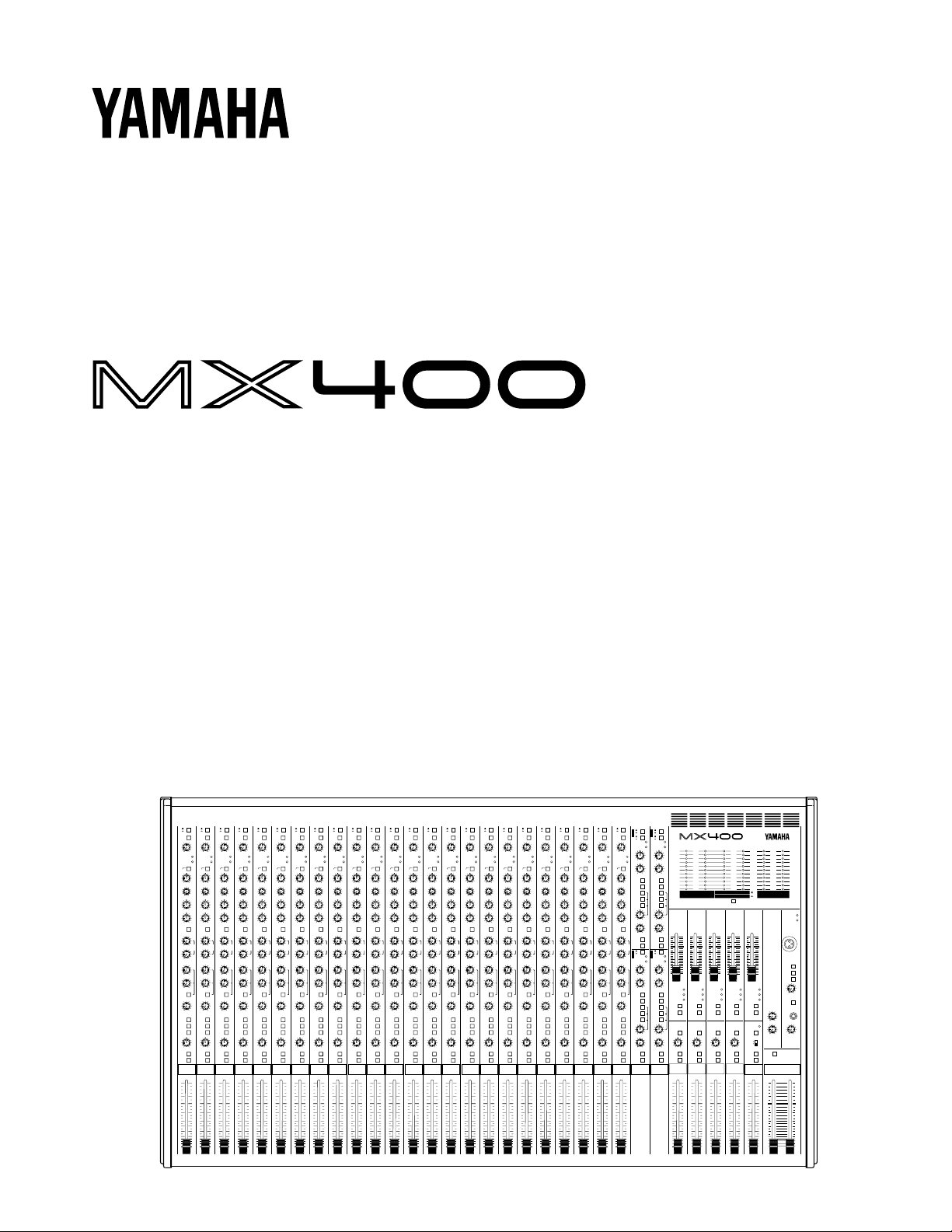
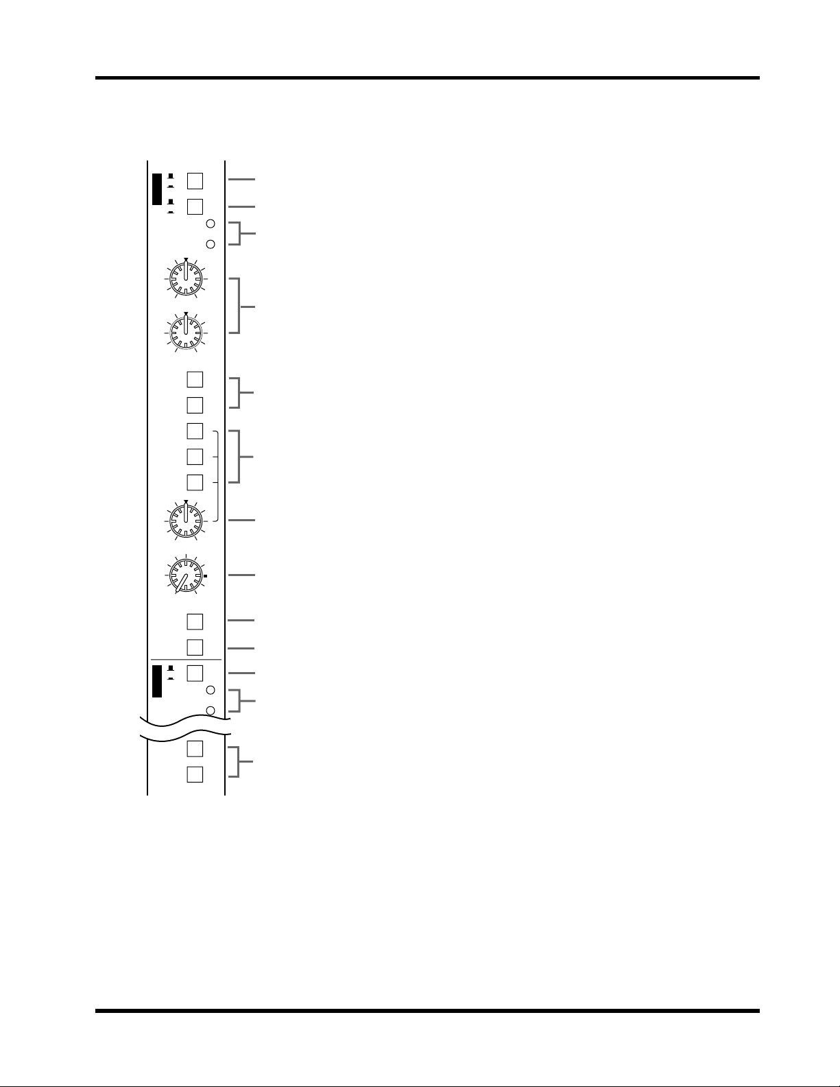
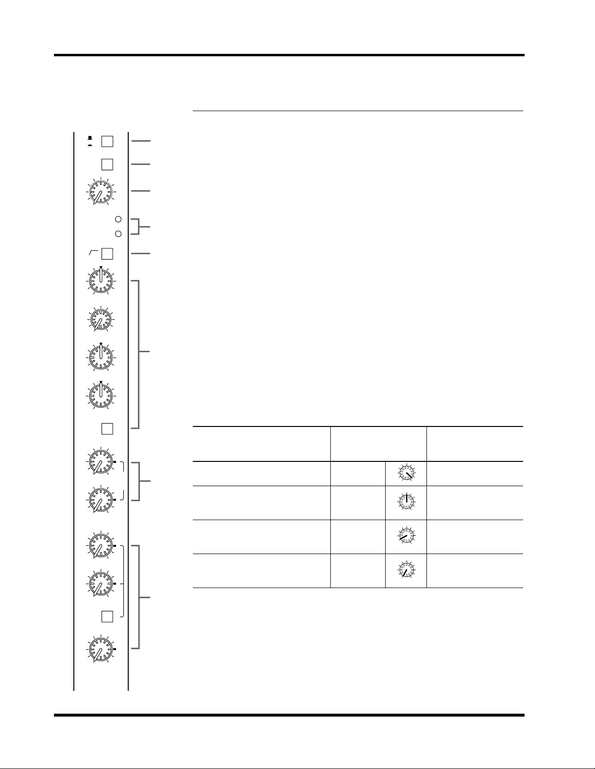
Input modules
1
A/B switch
This switch selects the signal source of the input module.
Select INPUT A (XLR type) or INPUT B (1/4” phone type).
2
20dB pad switch
This is a 20dB input pad (attenuator) that affects INPUT A and INPUT B.
If the level of the input signal is too high for adjustments to be made using
the GAIN control alone, use the pad to attenuate the signal to an appropriate
level. The pad is on when this switch is pressed in.
3
GAIN control
This controls the gain of the preamp for INPUT A and INPUT B. Gain is
variable to a maximum of 44dB.
The GAIN control is always used in conjunction with the SIGNAL indicator
and the PEAK indicator. Adjust the GAIN control so that the SIGNAL indicator is always lit when an input signal is present, and the PEAK indicator
lights occasionally. If the PEAK indicator lights frequently, lower the GAIN
control to prevent the signal from distorting.The following table shows
usual settings for the GAIN control.
Signal source GAIN control position 20dB pad switch
Dynamic mic (low level) –60 ~ –50 off
010
AUX 1
010
AUX 2
010
AUX 3
010
AUX 4
PRE
010
AUX 5
MX400 User’s Guide
Condenser mic (high level) –35 off
P
R
7
E
Audio device, electronic musical instrument (low level)
Audio device, electronic musical instrument (high level)
4
SIGNAL indicator and PEAK indicator
–20 off
+4 on
When the post EQ signal level (nominal level 0dB) reaches –10dB, the SIGNAL indicator will light. This indicator indicates that a signal is being input.
8
When the post EQ signal level reaches 3dB before clipping level, the PEAK
indicator will light. This indicator indicates that the signal has approached
clipping level. Set the signal level based on the status of the PEAK indicator.
P
O
S
T
For the procedure, see the explanation for
GAIN control.
3
10k 20k1k10020
–20
–10
0
10
20
Frequency (Hz)
Signal Level (dB)
50 5k2k500200 50k
MID FREQ
250
5k
Input modules
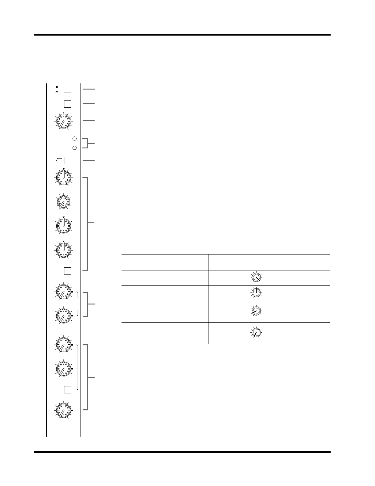
5
high pass filter switch
80
This switch cuts the input signal below 80 Hz at 12dB/octave. The filter is
turned on when the switch is pressed in.
By using the high pass filter, you can reduce or eliminate wind noise, mic
pop noise, and power supply hum etc.
6
EQ controls (HIGH, MID FREQ, MID, LOW)
This is a 3-band equalizer with center frequencies, range, and type as shown
below.
HIGH: 12 kHz +/–15dB shelving type
MID: 250 Hz ~ 5 kHz (variable) +/–15dB peaking type
LOW: 80 Hz +/–15dB shelving type
The frequency response is flat when the knob is in the center position.
3
EQ switch
This switch turns the EQ on/off. When the switch is pressed in the EQ is on.
In addition to bypassing the EQ when it is not being used, this switch provides a convenient way to compare the equalized and unequalized signals.
7
AUX 1 / AUX 2 controls
These adjust the signal level that is sent to each output AUX SEND 1 and
AUX SEND 2. These signals are pre-fader (i.e., they are taken from before
the fader adjustment). Nominal level is at 3 o’clock position.
AUX 3 / AUX 4 / AUX 5 controls
8
These adjust the signal level that is sent to each output AUX SEND 3, AUX
SEND 4 and AUX SEND 5.
The signals controlled by AUX 3 and AUX 4 will depend on the setting of
the PRE switch.
• When the PRE switch is not pressed
They control the post-fader signal.
• When the PRE switch is pressed
They control the pre-fader signal.
AUX 5 controls the post-fader signal.
Nominal level is at 3 o’clock position.
MX400 User’s Guide
Front and rear panels
4
1–2
3–4
ST
L
ON
PFL
PAN
EVEN
ODD
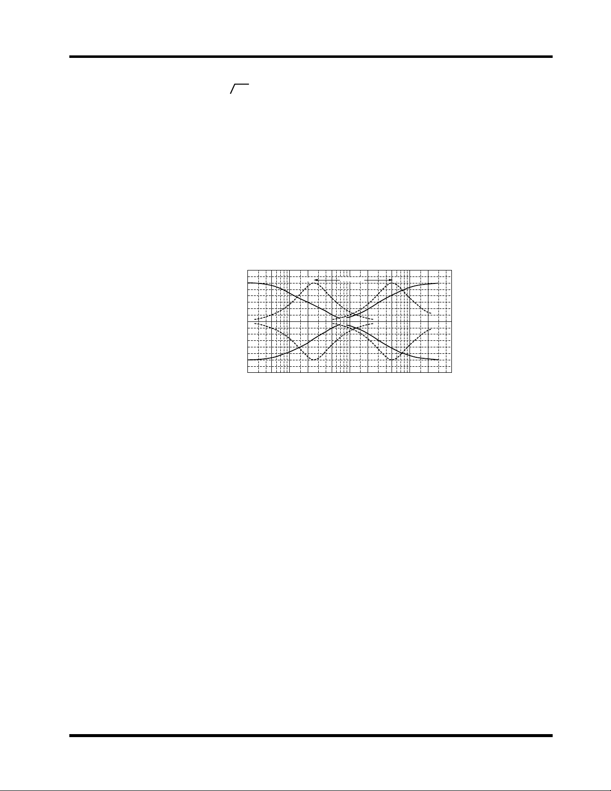
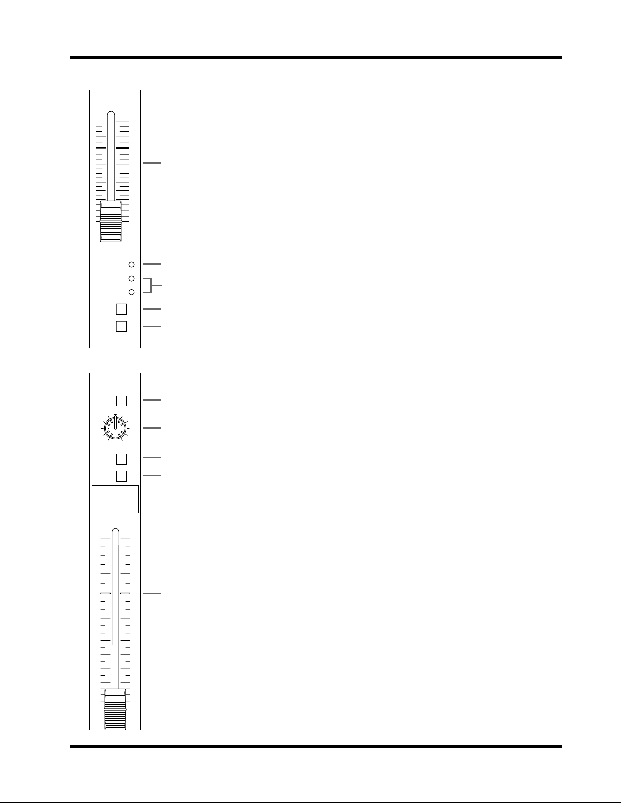
9
Assign switches (1-2, 3-4, ST)
These switches assign the signal of the input module to the group outputs
and the ST output. The PAN control located below adjusts the stereo posi-
9
tion of the signal between the odd (ODD) group and left (L) outputs and
the even (EVEN) group and right (R) outputs.
0
PAN control
R
0
This knob adjusts the stereo position of the signal between the stereo L and
R, and between the odd/even groups. For example if this knob is turned all
the way to the left, the signal will be sent only to the L and odd (ODD) groups
A
B
whose assign switches are pressed. If it is turned all the way to the right, the
signal will be sent only to the R and even (EVEN) groups. If the knob is set
to the center position, the same amount of signal will be sent to the stereo
L and R, and the odd/even groups.
A
ON switch
This switch turns the input module on/off. When the switch is pressed in
10
the input module is on. Be sure to turn off input modules that are not in
use. Even when a module is off, the SIGNAL and PEAK indicators will light
if a signal is being input. You can also use the PFL switch to monitor the sig-
5
nal even if a module is off.
B
0
C
PFL switch
PFL is an acronym for Pre-Fader Listen. This switch allows you to monitor
5
10
15
20
25
30
40
the signal of the input module regardless of the fader position, the settings
of the ON switch, the group assign switches, or the AUX settings. As the
name suggests, the signal is taken pre-fader (post EQ). You may listen to an
individual module, or to two or more modules simultaneously. The PFL
indicator located at the top of the STEREO module will light when a PFL
switch is on.
C
Fader
This adjusts the signal level that is sent to the various outputs. Faders are
∞
used individually or in conjunction with the faders of the other input modules to create the desired mix balance. A position at the zero (0) marking is
the nominal level. Raising the fader above 0 provides up to 10dB of gain.
MX400 User’s Guide
A
S
B
T
1
+4
-10
PEAK
SIGNAL
–15 +15
HIGH
–15 +15
LOW
AUX 1
AUX 2
1–2
3–4
ST
L
ODD
BAL/PAN
010
LEVEL
ON
PFL
+4
S
-10
T
PEAK
3
SIGNAL
AUX 3
AUX 4
EVEN
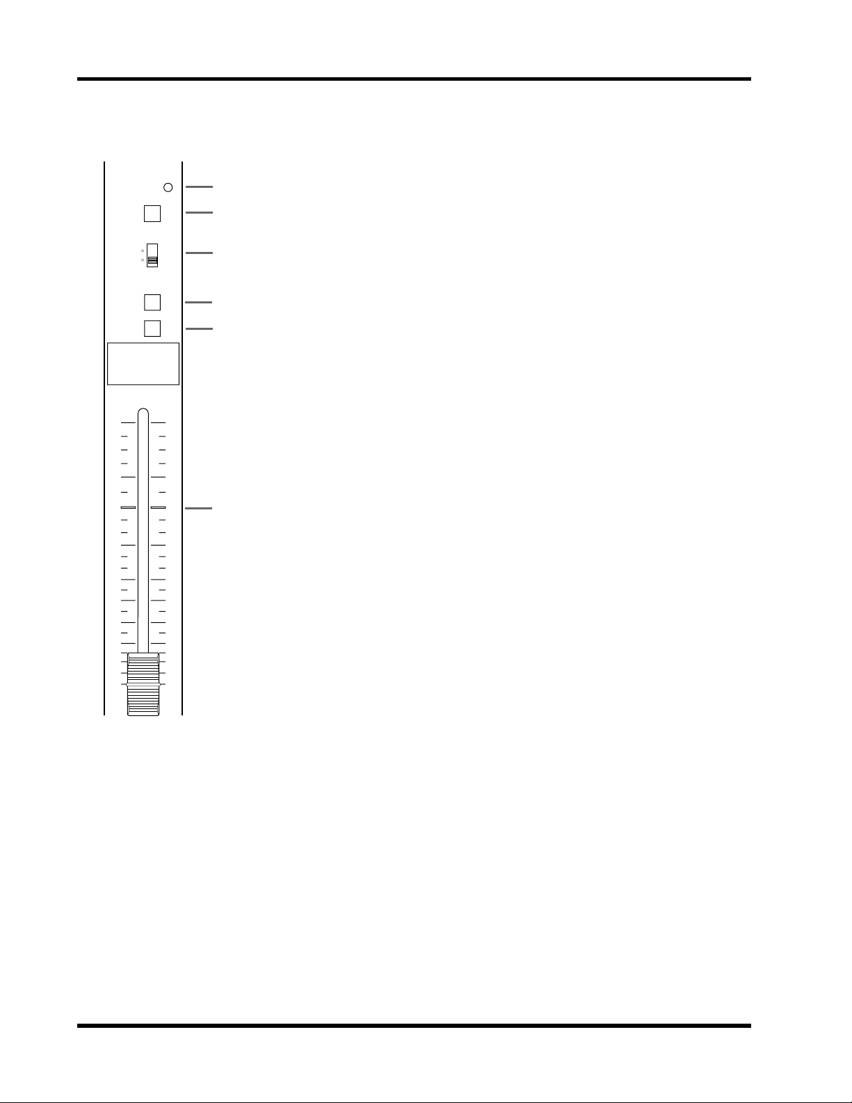
Stereo module
5
Stereo module
1
A/B switch
1
2
3
4
5
6
7
R
8
9
0
2
3
5
This switch selects the signal source for the stereo module.
Select either ST INPUT A (unbalanced 1/4” phone type) or ST INPUT B
(RCA pin) input. This switch is not provided for [ST3] or [ST4].
2
Sensitivity select (+4/–10) switch
This switch selects the gain appropriate for the input signal level. The sensitivity is –10dB when the switch is pressed in, and +4dB when the switch
is not pressed in.
3
SIGNAL and PEAK indicators
When the post EQ signal level (nominal level 0dB) reaches –20dB, the SIGNAL indicator will light. This indicator indicates that a signal is being input.
When the post EQ signal level reaches 3dB before clipping level, the PEAK
indicator will light. This indicator indicates that the signal has approached
clipping level. Set the signal level based on the status of the PEAK indicator.
4
EQ controls (HIGH, LOW)
This is a 2-band equalizer with center frequencies, range, and type as shown
below.
HIGH: 12 kHz +/–15dB shelving type
LOW: 80 Hz +/–15dB shelving type
The frequency response is flat when the knob is in the center position.
5
AUX 1 / AUX 2 / AUX 3 / AUX 4 switches
These switches send the mono signal to the AUX buses. They are on when
pressed in.
[ST1] and [ST2] select the AUX 1 and AUX 2 buses.
[ST3] and [ST4] select the AUX 3 and AUX 4 buses.
6
Assign switches (1-2, 3-4, ST)
These switches assign the signal of the stereo module to the group outputs
and the ST output. The PAN control located below adjusts the stereo position of the signal between the odd (ODD) group and left (L) outputs and
the even (EVEN) group and right (R) outputs.
7
BAL/PAN control
The BAL/PAN knob adjusts the balance or the L/R position of the stereo
module signal. For example if this knob is turned all the way to the left, the
signal will be sent only to the L and odd (ODD) groups whose assign
switches are pressed. If it is turned all the way to the right, the signal will be
sent only to the R and even (EVEN) groups. If the knob is set to the center
position, the same amount of signal will be sent to the stereo L and R, and
the odd/even groups.
8
LEVEL control
This adjusts the output level of the stereo module.
MX400 User’s Guide

Front and rear panels
6
9
ON switch
This switch turns the stereo module on/off. When the switch is pressed the
stereo module is on. Be sure to turn off input modules that are not in use.
Even when a module is off, the SIGNAL and PEAK indicators will light if a
signal is being input. You can also use the PFL switch to monitor the signal
even if a module is off.
0
PFL switch
PFL is an acronym for Pre-Fader Listen. This switch allows you to monitor
the signal of the stereo module regardless of the fader position, the settings
of the ON switch, the group assign switches, or the AUX settings. As the
name suggests, the signal is taken pre-fader (post EQ). You may listen to an
individual module, or to two or more modules simultaneously.
MX400 User’s Guide
ON
AFL
PEAK
–20
AUX SEND module
7
AUX SEND module
10
5
0
5
1
10
15
20
30
40
∞
2
0
3
4
5
1
AUX SEND fader
This adjusts the signal level of the AUX SEND output. A position at the zero
(0) marking is the nominal level. Raising the fader above 0 provides up to
10dB of gain.
2
PEAK indicator
This indicator lights when the level of the input signal reaches 3dB before
clipping.
3
Signal (0/–20) indicator
The 0dB indicator (yellow) lights when the output signal level reaches +4dB.
The –20dB indicator (green) lights when the output signal reaches –16dB.
4
ON switch
This switch turns the AUX SEND on/off. When the switch is pressed in it is
turned on. When off, no signal will be output from the corresponding AUX
SEND jack.
5
AFL (After Fader Listen) switch
This monitors the AUX SEND signal. This is on when the switch is pressed
in.
TO ST
LR
PAN
ON
AFL
1
2
3
4
GROUP module
1
TO ST switch
This sends the GROUP signal to the stereo bus.
2
PAN control
This adjusts the panning of the signal sent to the stereo bus.
3
ON switch
This switch turns the GROUP on/off. The group is on when the switch is
pressed in. When off, no signal will be output from the corresponding
GROUP OUT jack.
10
4
AFL (After Fader Listen) switch
This monitors the GROUP signal. This is on when the switch is pressed in.
5
0
5
5
10
15
20
25
30
40
∞
5
Group fader
This fader adjusts the signal level of the GROUP output.
MX400 User’s Guide
8 Front and rear panels
PFL
2TR IN
MONI
ST2
ON
1
2
3
4
ST2/MONITOR module
1 PFL indicator
This indicator (yellow) will light when the PFL switch of one or more modules is turned on.
2 2TR IN switch
This switch selects the 2TR IN input signal. This signal will be sent to the
headphone jack and to the ST2/MONI OUT jack. When this switch is on,
the 2TR IN input signal will be sent regardless of each module’s PFL and
AFL switch settings.
L+R
5
3 MONI/ST2 switch
This switch selects the signal that is output to the ST2/MONI OUT jack.
When the switch is in the “ST2” position, the signal will be the same as the
signal that is sent to the ST1 OUT jack. When the switch is in the “MONI”
position, the signal will be taken from the PFL bus, AFL bus, or the 2TR IN
10
jack.
4 ON switch
5
0
6
This switch turns the ST2/MONITOR module on/off. When the switch is
pressed in the module is on. When the module is off, no signal will be output
from the ST2/MONI OUT jack.
5 L+R switch
5
10
15
20
25
30
40
∞
This switch causes a mono mixed signal to be output from the ST2/MONI
OUT jack.
6 ST2/MONITOR fader
This fader controls the signal level of the ST2/MONITOR output.
MX400 User’s Guide
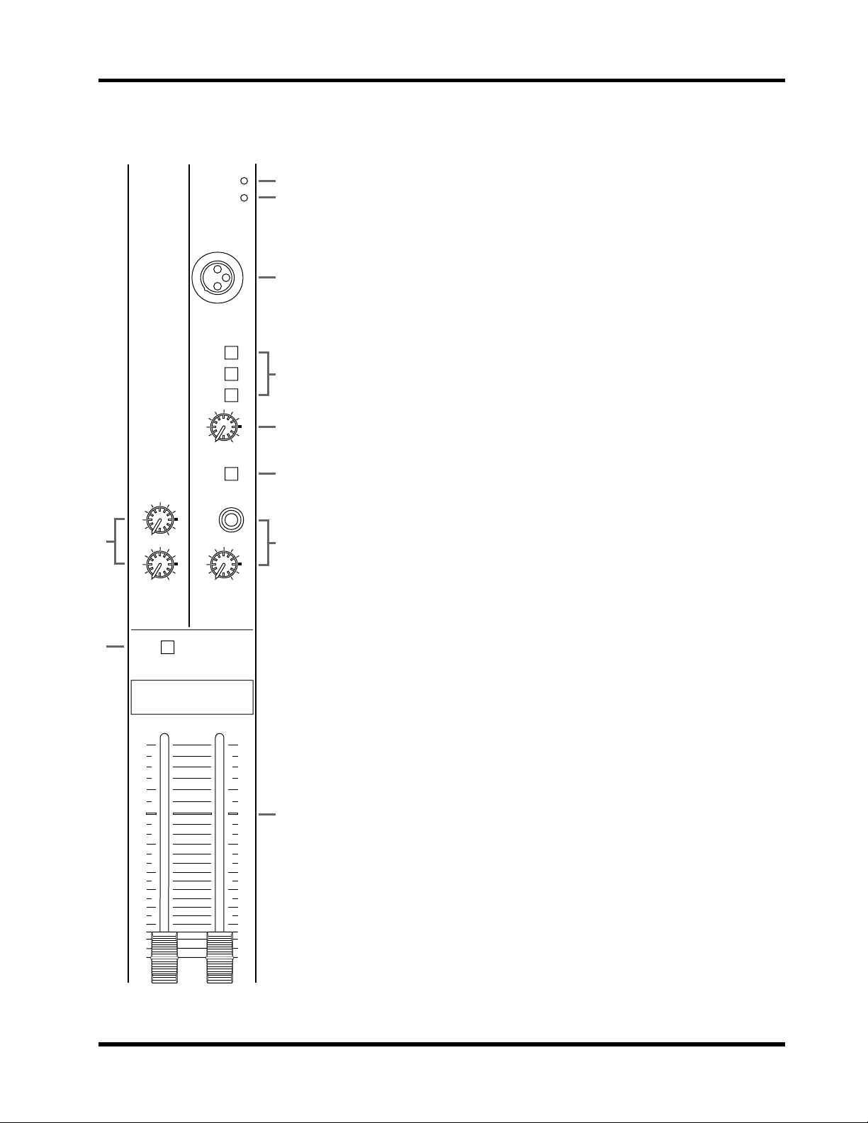
Master module (L-ST1-R) 9
Master module (L-ST1-R)
8
9
010
REC OUT
010
TAPE IN
ON
POWER
PHANTOM
TALKBACK IN
GRP 1–4
AUX 1–4
ST
010
LEVEL
TB
010
PHONES
1 POWER indicator
1
2
This indicator lights when the power switch is turned on.
2 PHANTOM indicator
This indicator lights when the PHANTOM switch is turned on, indicating
that phantom power is being supplied.
3
3 TALKBACK IN jack
This is an unbalanced XLR type jack for connecting a talkback mic. The
nominal input level is –50dB.
4 Assign switches (GRP 1-4, AUX 1-4, ST)
4
These switches select the output destination (mix bus) of the talkback mic.
5 LEVEL control
5
This adjusts the signal level of the talkback mic.
6 TB switch
6
This switch controls the talkback signal. When it is pressed, the talkback signal will be sent to the output destination selected by the assign switch located
above.
7 Headphone jack / PHONES control
7
This is a 1/4” stereo phone jack for connecting a set of stereo headphones.
Headphones connected here can be used to monitor PFL, AFL, and the 2TR
IN signals.
8 REC OUT / TAPE IN controls
The REC OUT control adjusts the output signal level of the REC OUT jack.
The TAPE IN control adjusts the input signal level of the TAPE IN jack.
10
5
0
5
10
15
20
25
30
40
∞
L — ST 1 — R
9 ON switch
This switch turns the ST1 OUT output on/off. When it is pressed in, the signal from the ST1 OUT jack will be output.
10
5
0
5
10
15
20
25
30
40
∞
0 L-ST1-R faders
These faders control the level of the ST OUT output. A position at the zero
(0) marking is the nominal output level.
0
MX400 User’s Guide
10 Front and rear panels
Meters
PEAK
+6
+4
+2
0
–2
–4
–7
–10
–15
–20
LRSTEREO 1
1
PEAK
+6
+4
+2
0
–2
–4
–7
–10
–15
–20
GROUP 1 GROUP 2 GROUP 3 GROUP 4
PEAK
+6
+4
+2
0
–2
–4
–7
–10
–15
–20
LRST2/MONITOR
METER SELECT
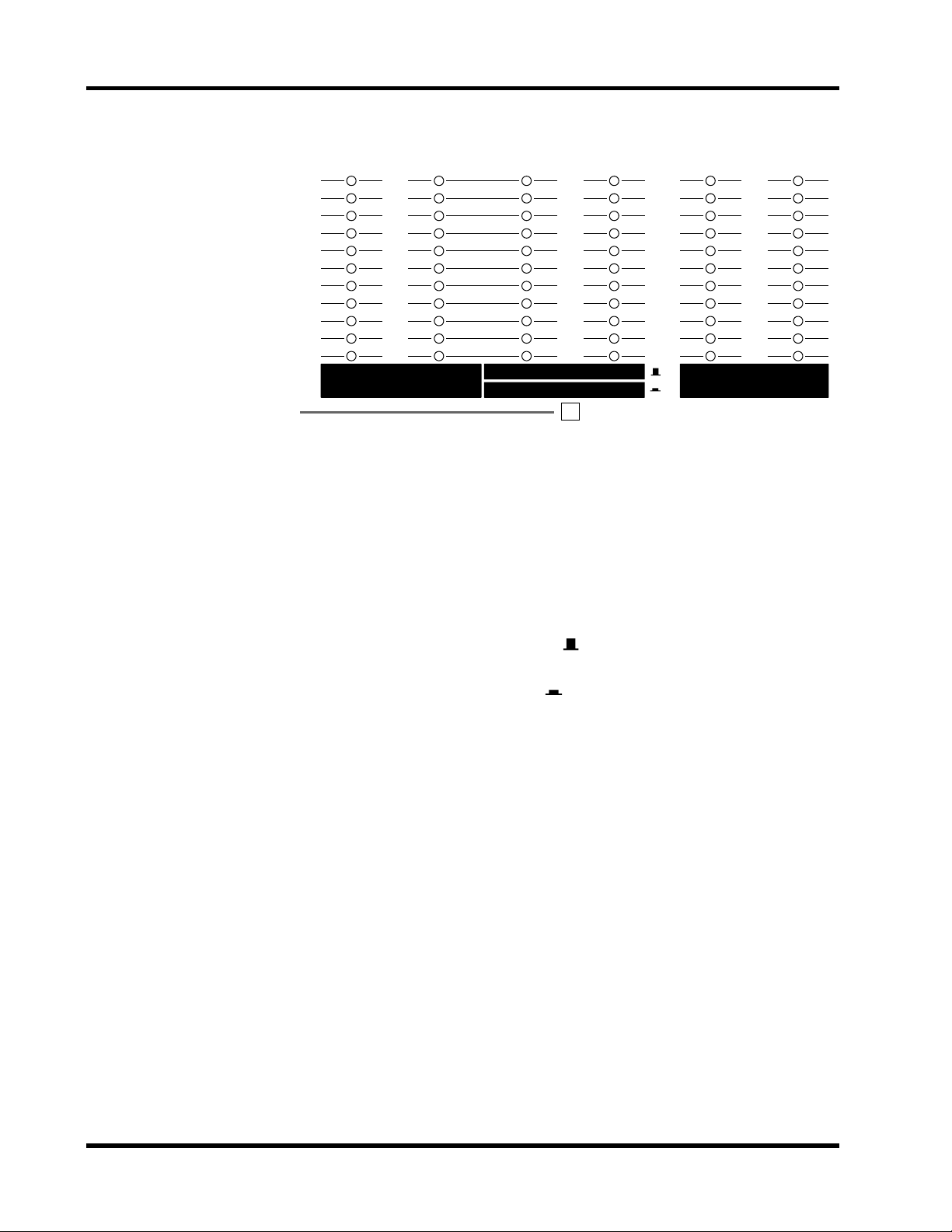
The MX400 provides six LED meters, and three types of output level can be
viewed on the meters. 1) GROUP 1/2, 2) GROUP 3/4 or ST2/MONITOR L/R,
3) STEREO L/R.
The “0” position indicates the nominal output level.
The “PEAK” position indicates that the output level is 3dB before clipping.
1 METER SELECT switch
This switch selects whether GROUP 3/4 or ST2/MONITOR L/R will be
monitored.
When the switch is not pressed in ( ), the central meter group will indicate
the GROUP 3/4 signal level.
When the switch is pressed in ( ), the central meter group will indicate
the ST2/MONITOR L/R signal level.
MX400 User’s Guide
Rear panel 11
INSERT
OUT IN
87654321
87654321
87654321
87654321
DIRECT OUT 0dB
INSERT I/O 0dBINPUT
INPUT B
INPUT A
1
2
3
4
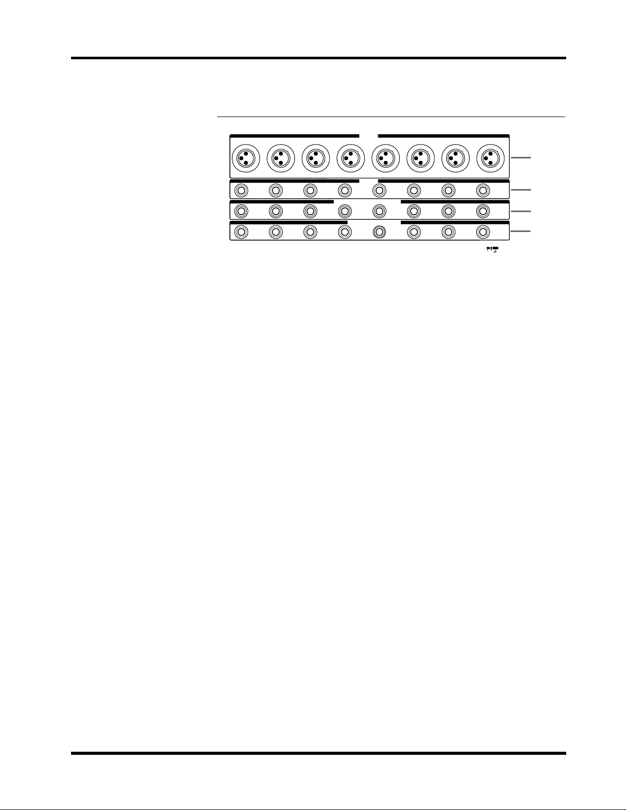
Rear panel
1 INPUT A jacks
These are unbalanced XLR3-31 type jacks which input the signal for each
input module. Use the A/B switch to select these jacks.
• Nominal input level: –60dB
Phantom power (+48 V) can be supplied to these jacks. Phantom power is
turned on/off using the PHANTOM switch.
When the PHANTOM switch is on, make sure that those devices which do
not require phantom power are connected to the INPUT B jacks (
2).
2 INPUT B jacks
These are 1/4” phone jacks which input the signal for each input module.
Use the A/B switch to select these jacks. These are balanced TRS jacks, with
tip=hot, ring=cold, and sleeve=ground.
• Nominal input level: –60dB
3 INPUT INSERT I/O jacks (0dB)
These are 1/4” phone jacks patched in front of the input module faders.
These are unbalanced TRS jacks, with tip=out, ring=in, and sleeve=ground.
• Nominal input level: 0dB
• Nominal output level: 0dB
4 DIRECT OUT jacks (0dB)
These are unbalanced 1/4” phone jacks which output the post-fader signal
independently from each input module.
• Nominal output level: 0dB
MX400 User’s Guide
12 Rear panel
Phantom Power Warning
To prevent hazard or damage, connect
only microphones and cables that
conform to the IEC268-15A standard.
9-E FNTM 01 3/5
C
D
F
G
H
E
AUX SEND +4dB
54321
GROUP INSERT I/O 0dB
4321
GROUP OUT +4dB
4321
ST2/MONI OUT +4dB
RL
ON OFF
POWER
ON OFF
ST INSERT
ST1 OUT +4dB
RL
PHANTOM+48V
I/O
L
0dB
R
5
GROUP SUB IN +4dB
21
43
2TR IN ST SUB IN
L
–10dBV
R
TAPE INREC OUT
L
–10dBV
–10dBV
R
+4dB
ST INPUT 2
L
R
ST INPUT 4
L
R
ST INPUT 1
L/
MONO
R
L
R
L/
MONO
R
L/
MONO
ST INPUT 3
R
L
R
L/
MONO
R
A
A
BB
I
6J
789
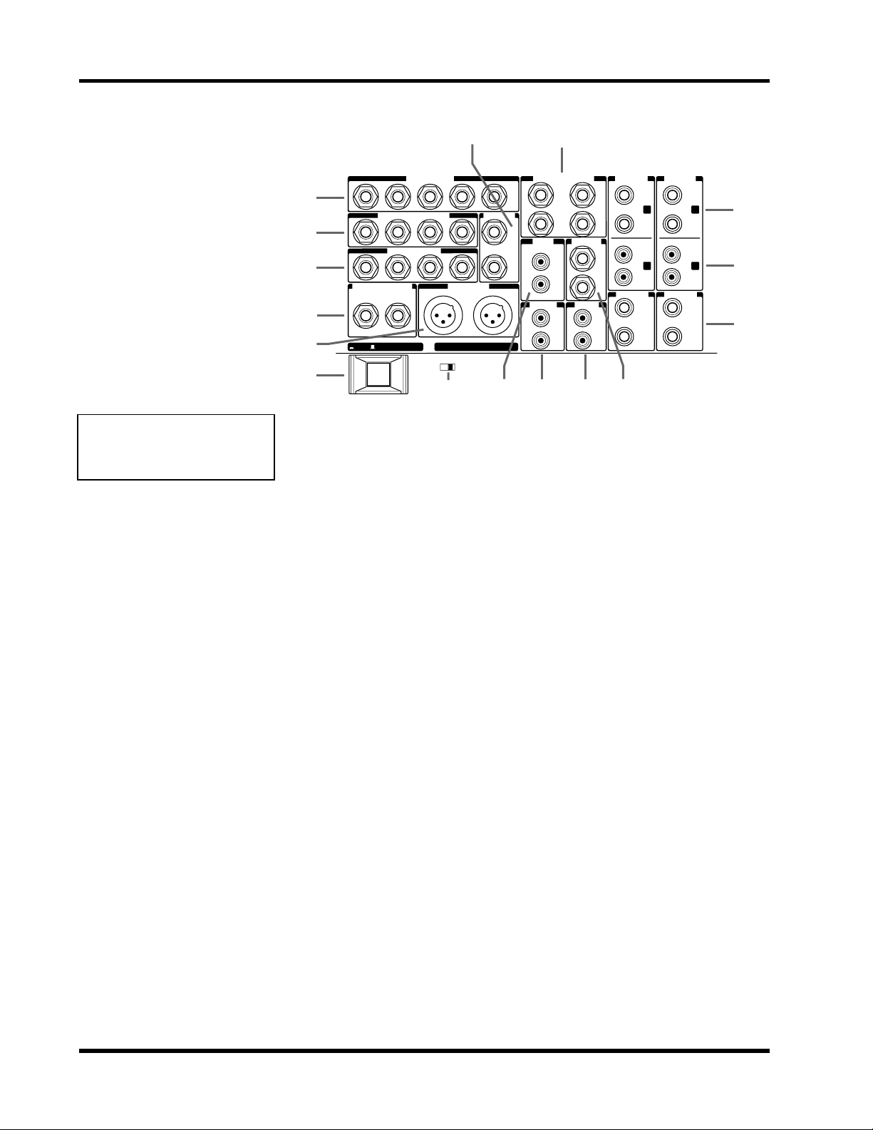
5 GROUP SUB IN jacks (+4dB)
These are unbalanced 1/4” phone jacks which input signals from sub-mixers
or other devices.
• Nominal input level: +4dB
6 2TR IN jacks (–10dBV)
These are RCA pin jacks used to input a stereo sound source.
• Nominal input level: –10dBV
0
A
B
7 ST SUB IN jacks (+4dB)
These are 1/4” unbalanced phone jacks which input a stereo signal from a
sub-mixer or other source.
• Nominal input level: +4dB
8 REC OUT jacks (–10dBV)
These are RCA pin jacks which output a stereo signal to a DAT or cassette
recorder. These jacks are positioned before the stereo master fader.
• Nominal output level: –10dBV
9 TAPE IN jacks (–10dBV)
These are RCA pin jacks which input a stereo source such as a DAT, stereo
cassette deck, or CD player.
• Nominal input level: –10dBV
0 ST INPUT 1/2 A jacks
These are unbalanced 1/4” phone jacks which input a stereo source. These
jacks are selected by the A/B switch.
• Nominal input level: +4dB or –10dB
A ST INPUT 1/2 B jacks
These are RCA pin jacks which input a stereo source. These jacks are selected
by the A/B switch.
• Nominal input level: +4dB or –10dB
MX400 User’s Guide

O u t
Rear panel 13
B ST INPUT 3/4 jacks
These are unbalanced 1/4” phone jacks which input a stereo source.
• Nominal input level: +4dB or –10dB
C AUX SEND jacks (+4dB)
These are unbalanced 1/4” phone jacks which output the signals of the AUX
SEND buses.
• Nominal output level: +4dB
D GROUP INSERT I/O jacks (0dB)
G round
In
These are 1/4” phone jacks patched in front of the GROUP faders. These
TRS jacks are unbalanced.
• Nominal output level: 0dB
• Nominal input level: 0dB
Tip=out, Ring=in, Sleeve=ground
E ST INSERT I/O jacks (0dB)
These are 1/4” phone jacks patched in front of the L-ST1-R fader of the master module. These TRS jacks are unbalanced, with Tip=out, Ring=in, and
Sleeve=ground.
• Nominal output level: 0dB
• Nominal input level: 0dB
F GROUP OUT jacks (+4dB)
These are unbalanced 1/4” jacks which output the signals of the GROUP
buses.
• Nominal output level: +4dB
G ST2/MONI OUT jacks (+4dB)
These are unbalanced 1/4” jacks which output the signal of the STEREO L,R
bus or the signal of the MONITOR bus.
• Nominal output level: +4dB
H ST1 OUT jacks (+4dB)
These are balanced XLR3-32 type jacks which output the signal of the stereo
L,R bus.
• Nominal output level: +4dB
I POWER switch
This switch turns the power on/off. When in the “ON” position, the POWER
indicator will light.
J PHANTOM power switch
This switch turns the internal phantom power supply on/off. When in the
“ON” position, the PHANTOM indicator will light, and 48 DC power will
be provided between pin 2 and pin 3 of the INPUT A jacks.
If you do not need phantom power, be sure to turn this to the “OFF” position.
MX400 User’s Guide
14 Appendix
Appendix
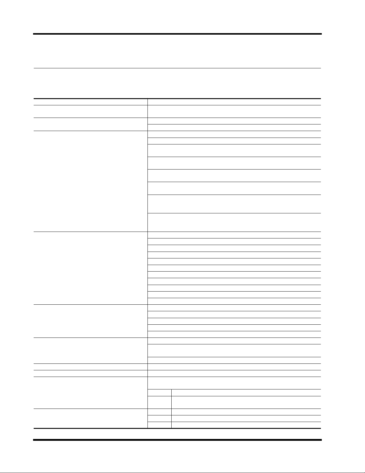
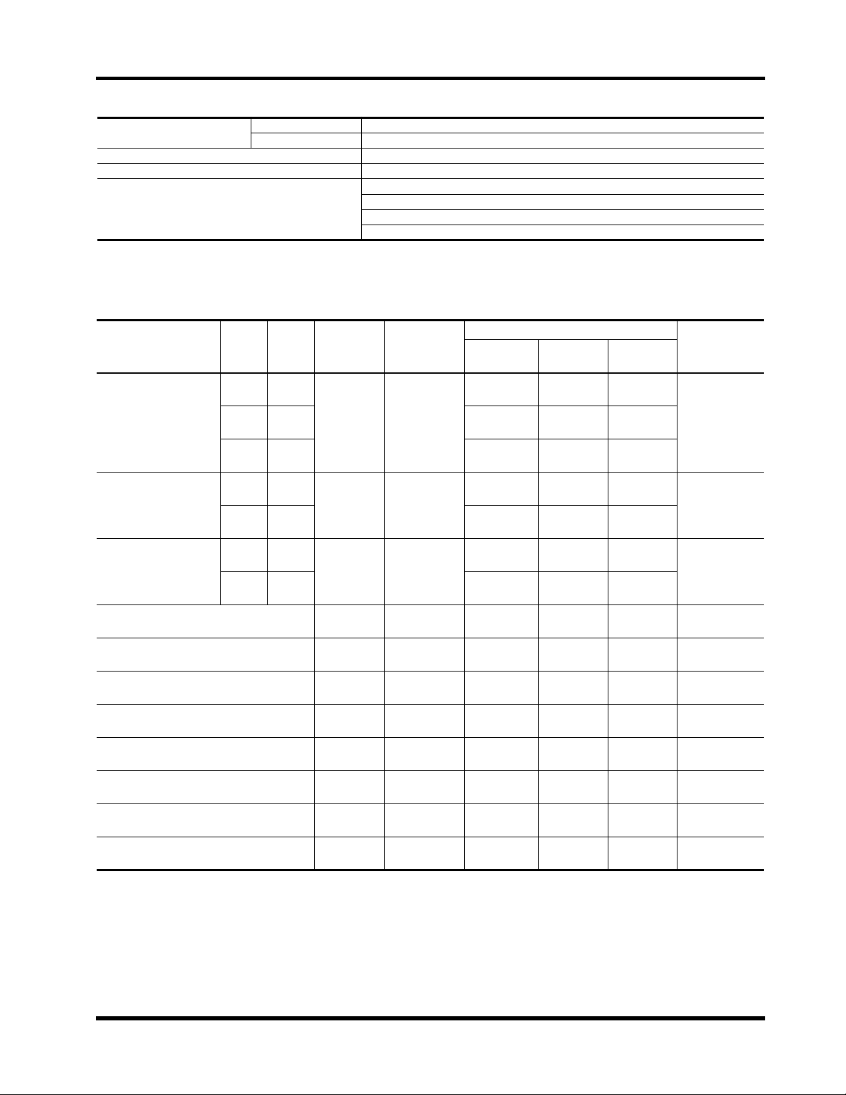
General specifications.
Frequency response
Total harmonic distortion
Crosstalk (@1 kHz)
Hum & Noise (Average, Rs=150 Ω)
(Measured with BPF 20 Hz~20 kHz)
Maximum voltage gain
Input module EQ
ST input module EQ
Input module HPF
Input module GAIN control
Meters (0 LED = +4dB* output level)
Input module, stereo input module indicators
AUX SEND indicators
20 Hz~20 kHz +1, –2dB (ST L/R, GROUP @ 600 Ω AUX SEND @ 600 Ω)
Less than 0.1% (20 Hz~20 kHz @ 14dB*) (ST L/R, GROUP @ 600 Ω AUX SEND
@ 600 Ω)
–70dB (between adjacent channels)
–70dB (between outputs)
–128dB* equivalent input noise (CH 1~24)
–96dB* residual noise (STEREO 1,2, GROUP 1~4, AUX SEND 1~5)
–87dB* (STEREO 1,2, GROUP 1~4) Measured with master faders at nominal
level and all assign switches off
–64dB* (SN ratio = 68dB) (STEREO 1,2, GROUP 1~4) Measured with master
fader and input module 1 at nominal level position
–78dB* (AUX SEND 1~5) Measured with AUX SEND master faders at nominal
level and AUX controls of all modules at minimum position
–64dB* (SN ratio = 68dB) (AUX SEND 1~5) Measured with AUX SEND faders
and the AUX control of one module at nominal level position
–82dB* (STEREO 2/MONITOR) Measured with the ST2/MONITOR master fad-
er and PFL and AFL switched off for all modules. Measured with MONI/ST2
switch in the MONI position.
–64dB* (SN ratio = 68dB) (STEREO 2/MONITOR) Measured with the
ST2/MONITOR master fader and the PFL switch on for one module, and the
MONI/ST2 switch in the MONI position
84dB INPUT A/B → STEREO OUT 1,2
84dB INPUT A/B → GROUP OUT 1~4
80dB INPUT A/B → AUX SEND 1,2
90dB INPUT A/B → AUX SEND 3~5
28dB TAPE IN → STEREO OUT 1,2
30dB ST INPUT 1~4 → STEREO OUT 1,2, GROUP OUT 1~4
30dB ST INPUT 1~4 → AUX SEND 1~4
10dB GROUP SUB IN → GROUP OUT
10dB ST SUB IN → STEREO OUT
22dB 2TR IN → STEREO 2/MONITOR
70dB TALKBACK → STEREO OUT
Maximum variation +/–15dB
HIGH 12 kHz shelving type
MID 250 Hz~5 kHz peaking
LOW 80 Hz shelving type
* Turnover/roll-off frequency for shelving: 3dB before maximum variation
Maximum variation +/–15dB
HIGH 12 kHz shelving
LOW 80 Hz shelving
* Turnover/roll-off frequency: 3dB before maximum variation
80 Hz 12dB/oct
44dB variable –60dB~ –16dB
6 × 11 segment LED (–20, –15, –10, –7, –4, –2, 0, +2, +4, +6, PEAK), GROUP
1,2, GROUP 3,4 or ST2/MONITOR L,R, ST1 L,R
PEAK Lights red when post EQ signal reaches 3dB before clipping
SIGNAL Lights green when post EQ signal reaches 10dB before nominal lev-
el
PEAK Lights red when output signal reaches 3dB before clipping
0 Lights yellow when output signal reaches +4dB
–20 Lights green when output signal reaches –16dB
MX400 User’s Guide
Input Specifications 15
Power requirements
Weight
Power Consumption
Dimensions (W × H × D)
* 0dB=0.775V R.M.S
US&Canada model
General model
120V AC, 60Hz
230V AC, 50Hz
MX400-8 17kg, MX400-12 19kg, MX400-16 22kg, MX400-24 28kg
80W
MX400-8 562×180.2×596mm
MX400-12 682×180.2×596mm
MX400-16 802×180.2×596mm
MX400-24 1042×180.2×596mm
Input Specifications
Input Connection
INPUT A/B
STEREO INPUT 1, 2
STEREO INPUT 3, 4
INPUT INSERT IN 10k Ω 600 Ω lines
STEREO INSERT IN 10k Ω 600 Ω lines
GROUP INSERT IN 10k Ω 600 Ω lines
TAPE IN 10k Ω 600 Ω lines
STEREO SUB IN 10k Ω 600 Ω lines
GROUP SUB IN 10k Ω 600 Ω lines
2TR IN 10k Ω 600 Ω lines
TALKBACK 10k Ω 50~600 Ω mics
PAD
Switch
–20 –16
–10 —
–10 —
GAIN
Control
— –60
— –16
+4 —
+4 —
Actual Load
Impedance
4k Ω
5k Ω 600 Ω lines
5k Ω 600 Ω lines
For Use with
Nominal
50–600 Ω mics
600 Ω lines
&
Input level
Sensitivity *1 Nominal
–80dB
(77.5µV)
–36dB
(12.3mV)
–16dB
(123mV)
–12dB
(195mV)
–26dB
(38.8mV)
–12dB
(195mV)
–26dB
(38.8mV)
–20dB
(77.5mV)
–20dB
(77.5mV)
–20dB
(77.5mV)
–26dBV
(50mV)
–6dB
(388mV)
–6dB
(388mV)
–20dBV
(100mV)
–66dB
(388µV)
–60dB
(775µV)
–16dB
(123mV)
+4dB
(1.23V)
+4dB
(1.23V)
–10dB
(245mV)
+4dB
(1.23V)
–10dB
(245mV)
0dB
(775mV)
0dB
(775mV)
0dB
(775mV)
–10dBV
(316mV)
+4dB
(1.23V)
+4dB
(1.23V)
–10dBV
(316mV)
–50dB
(2.45mV)
Max. Before
Clip
–40dB
(7.75mV)
+4dB
(1.23V)
+24dB
(12.3V)
+24dB
(12.3V)
+10dB
(2.45V)
+24dB
(12.3V)
+10dB
(2.45V)
+20dB
(7.75V)
+20dB
(7.75V)
+20dB
(7.75V)
— RCA
+24dB
(12.3V)
+24dB
(12.3V)
+10dBV
(3.16V)
–30dB
(24.5mV)
Mixer
Connector
XLR-3-31 type
(A),
Phone jack (B)
*2
Phone jack *4
RCA
(switchable)
Phone jack *4
Phone jack
(TRS) *3
Phone jack
(TRS) *3
Phone jack
(TRS) *3
Phone jack *4
Phone jack *4
RCA
XLR-3-31 type
*5
*1. Sensitivity is the lowest input level that will produce an output of +4dB (1.23V) or the nominal output level when MX400 is set to
maximum gain (i.e. all level controls and faders set to maximum).
*2. XLR-type connectors and phone jacks (TRS) are balanced (Tip=HOT, Ring=COLD, Sleeve=shield).
*3. Insert phone jacks (TRS) are unbalanced (Tip=out, Ring=in, Sleeve=GND).
*4. Phone jacks are unbalanced.
*5. The talkback jack is unbalanced.
*6. In these specifications, when dB represents a specific voltage, 0dB is referenced to 775mV RMS,and when dBV represents a specific
voltage, 0dBV is referenced to 1V RMS.
MX400 User’s Guide
16 Appendix
Output Specifications
Output Connection
Actual Source
Impedance
For Use with
Nominal
Output Level
Nominal Max. Before Clip
Mixer Connector
ST1 OUT L/R 150 Ω 600 Ω lines +4dB (1.23V) +24dB (12.3V) XLR-3-32 type *1
STEREO INSERT OUT L/R 600 Ω 10k Ω lines 0dB (775mV) +20dB (7.75V) Phone jack (TRS)*2
ST2/MONI OUT L/R 75 Ω 600 Ω lines +4dB (1.23V) +20dB (7.75V) Phone jack *3
REC OUT L/R 600 Ω 10k Ω lines –10dBV (316mV) +16dBV (6.31V) RCA
GROUP 1~4 75 Ω 600 Ω lines +4dB (1.23V) +20dB (7.75V) Phone jack *3
AUX SEND 1~5 75 Ω 600 Ω lines +4dB (1.23V) +20dB (7.75V) Phone jack *3
INPUT INSERT OUT 600 Ω 10k Ω lines 0dB (775mV) +20dB (7.75V) Phone jack (TRS) *2
GROUP INSERT OUT 600 Ω 10k Ω lines 0dB (775mV) +20dBV (7.75V) Phone jack (TRS) *2
DIRECT OUT 600 Ω 10k Ω lines 0dB (775mV) +20dB (7.75V) Phone jack *3
PHONES OUT 100 Ω 40 Ω phones 3mW (346mV) 100mW (2.0V) Stereo phone jack
*1. XLR-type connectors and Phone jacks are balanced (Tip=HOT, Ring=COLD, Sleeve=GND).
*2. Insert phone jacks (TRS) are unbalanced (Tip=out, Ring=in, Sleeve=GND).
*3. Phone jacks are unbalanced.
*4. In these specifications, when dB represents a specific voltage, 0dB is referenced to 775mV RMS, for TAPE SEND dBV represents a specific
voltage, 0dBV is referenced to 1V RMS.
• All specifications subject to change without notice.
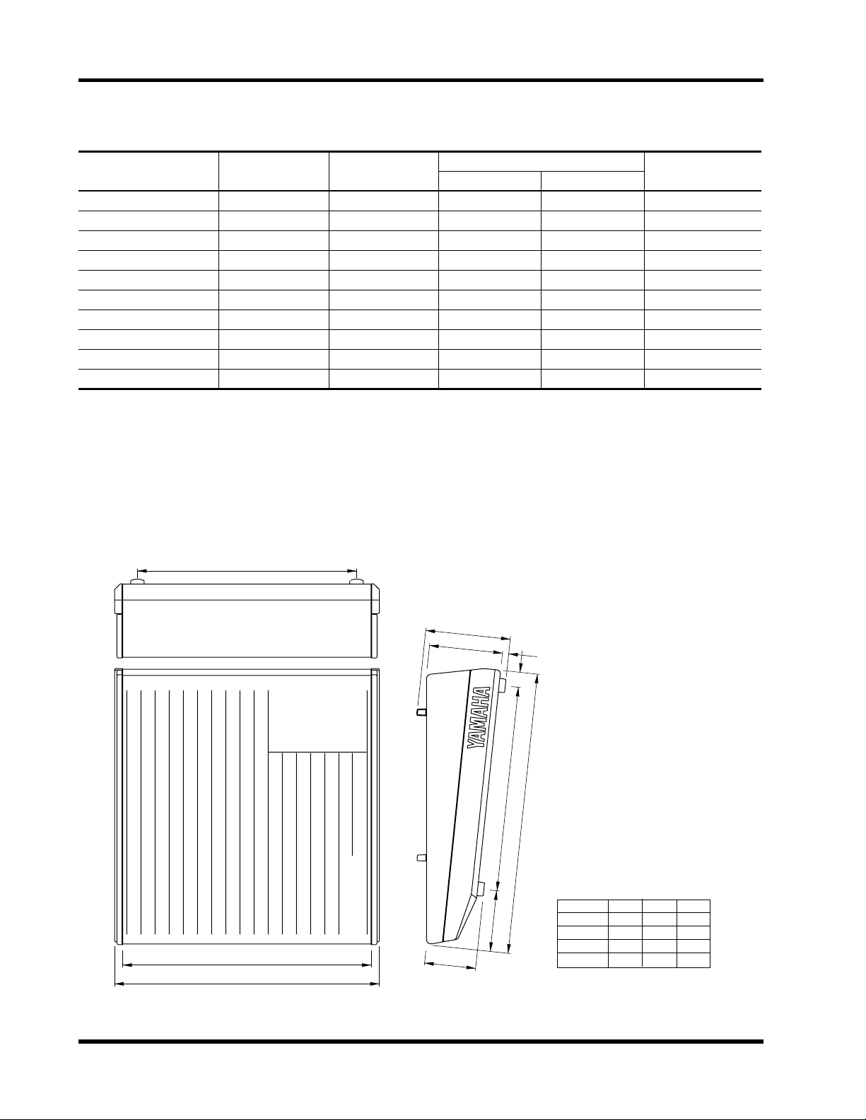
Dimensions
Wl
H: 180.2
155.5
Wi
W
108.9
129.5
31.9
434.5
D: 596
13.3
Model
MX400-8
MX400-12
MX400-16
MX400-24
WI
465
585
705
945
Wi
527
647
767
1007
W
562
682
802
1042
MX400 User’s Guide

CONSOLES DE MIXAGE
MANUEL D’UTILISATION
Français

i
Table des matières
1 Introduction . . . . . . . . . . . . . . . 1
Caractéristiques du MX400 . . . . . . . . . . . . . . . . 1
3 Panneau arrière . . . . . . . . . . 11
4 Appendice . . . . . . . . . . . . . . . 14
2 Panneaux avant et arrière . . . . 2
Modules d’entrée . . . . . . . . . . . . . . . . . . . . . . . . . 2
Module stéréo . . . . . . . . . . . . . . . . . . . . . . . . . . . 5
Module AUX SEND . . . . . . . . . . . . . . . . . . . . . . 7
Module GROUP . . . . . . . . . . . . . . . . . . . . . . . . . 7
Module ST2/MONITOR . . . . . . . . . . . . . . . . . . 8
Module Master (L-ST1-R) . . . . . . . . . . . . . . . . . 9
Indicateurs . . . . . . . . . . . . . . . . . . . . . . . . . . . . . 10
Spécifications générales.. . . . . . . . . . . . . . . . . . . 14
Spécifications d’entrée . . . . . . . . . . . . . . . . . . . 15
Spécifications de sortie . . . . . . . . . . . . . . . . . . . 16
Dimensions . . . . . . . . . . . . . . . . . . . . . . . . . . . . 16
Précautions
1. Emplacement
Evitez les emplacements soumis à de fortes températures (proximité de radiateur, poêles, etc.) ou une importante
humidité. Evitez également les endroits soumis à des vibrations qui pourraient entraîner un endommagement
mécanique ou les lieux particulièrement poussiéreux ainsi que les endroits sujets à d’importants champs magnétiques tels que la proximité du matériel de réception/transmission.
2. Aération
L’appareil est pourvu de fentes d’aération sur le panneau inférieur. Ne bouchez jamais ces orifices.
3. Evitez les chocs violents.
Des chocs violents peuvent endommager l’appareil. Maniez-le avec prudence.
4. N’ouvrez pas le boîtier et n’essayez pas de réparer ou modifier l’appareil vous-même.
Ce produit ne contient aucune pièce que vous pourriez réparer/remplacer. Veuillez consulter un service
après-vente Yamaha qualifié. L’ouverture du boîtier et/ou toute tentative de toucher aux circuits internes annule
la garantie.
5. Coupez toujours l’alimentation avant de procéder à des connexions.
Coupez toujours l’alimentation avant de brancher ou de débrancher des câbles. C’est particulièrement important pour éviter d’endommager l’appareil et le matériel qui y est branché.
6. Manipulez les câbles avec soin
Branchez et débranchez toujours les câbles (y compris le cordon d’alimentation) en prenant la fiche en main,
pas le câble.
7. Nettoyez avec un chiffon doux et sec
N’utilisez jamais de diluants tels que du benzène ou de la térébenthine pour nettoyer l’appareil. Nettoyez-le avec
un chiffon doux et sec.
8. Utilisez toujours une alimentation adéquate
Assurez-vous que la tension spécifiée sur le panneau arrière correspond à celle de votre secteur. Veillez également
à ce que les prises secteur puissent alimenter tout votre matériel.
MX400 Manuel d’utilisation

Introduction
Introduction
Nous vous remercions d’avoir porté votre choix sur le MX400 de Yamaha. Le
MX400 est conçu pour vous faciliter la vie et surtout pour pouvoir s’insérer dans
une vaste gamme de systèmes, y compris des systèmes d’amplification de salle
mobiles et fixes. La série MX400 comprend trois modèles: un mélangeur à 8
canaux, à 12 canaux, à 16 canaux et à 24 canaux.
Afin de pouvoir profiter pleinement des possibilités du MX400, veuillez lire attentivement ce manuel.
Caractéristiques du MX400
Chaque canal à entrée mono vous offre les fonctions suivantes:
• Prises XLR/jack
• Commutateur d’atténuation 20dB / commande de gain variable en continu
• Egalisation 3 bandes (avec bande moyenne variable) / commutateur EQ
On/Off /commutateur de filtre passe-haut
• Borne d’insertion TRS/ sortie directe
• Un total de 5 systèmes AUX SEND (pre
×
1)
• Groupes ODD/EVEN et commutateur d’assignation stéréo/ commande Pan.
• Commutateur Channel ON
• Commutateur PFL
• Indicateur de niveau de grande précision
Outre les canaux d’entrée mono, vous disposez de 4 jeux de canaux d’entrée stéréo
dotés des fonction suivantes:
• Quatre entrées stéréo avec égalisation à deux bandes
• Commutateur d’assignation GROUP/AUX/ST
• Commande de balance/pan
• Commutateur de sélection, prise d’entrée TRS 1/4” et prise RCA (uniquement pour entrée stéréo 1/2)
La section master offre les caractéristiques suivantes:
• Cinq commandes AUX SEND de type curseur
• Indicateur indépendant à trois points pour chaque commande AUX SEND
• Commutateur TO ST et commande Pan pour chaque GROUP.
• Commutateur GROUP ON, commutateur AFL et curseur 100mm pour
chaque GROUP
• L e commutateur MONI/ST2 permet de commuter le signal de sortie
ST2/MONI OUT de deux façons:
1) Un des signaux d’une source externe entre par le bus stéréo, le bus PFL ou
le bus 2TR IN.
2) Le même signal comme signal de sortie STI1 OUT.
• Un commutateur ON, L+R , et un curseur contrôlent le signal de sortie
ST2/MONI OUT.
Vous trouverez en outre les fonctions suivantes:
• Entrées XLR pour micro
• Commande de niveau Talkback
• Commutateur d’assignation
Les prises TAPE IN et REC OUT ont respectivement des commandes de niveau,
pratique lorsque vous avez besoin d’une marge supplémentaire pour l’écoute ou
l’enregistrement. Les indicateurs de niveau vous offrent un contrôle précis.
×
2, post/pre × 2 (commutatble), post
1
MX400 Manuel d’utilisation
–16
–60
GAIN
–16
–60
GAIN
–16
–60
GAIN
–16
–60
GAIN
Panneaux avant et arrière
2
Panneaux avant et arrière
A
B
20dB
–16 –60
GAIN
PEAK
SIGNAL
80
–15 +15
HIGH
250 5K
MID FREQ
–15 +15
MID
–15 +15
LOW
EQ
1
2
3
4
5
6
Modules d’entrée
1
Commutateur A/B
Ce commutateur sélectionne la source de signal du module d’entrée.
Sélectionne INPUT A (type XLR) ou INPUT B (type jack 1/4).
2
Commutateur d’atténuation 20dB
Il s’agit d’un atténuateur d’entrée de 20dB qui affecte INPUT A et INPUT B.
Si le niveau du signal d’entrée est trop haut pour effectuer des réglages au
moyen de la commande GAIN uniquement, utilisez le commutateur d’atténuation pour ramener le signal à un niveau adéquat. L’atténuation est activée lorsque le commutateur est enfoncé.
3
Commande GAIN
Cette commande contrôle le gain du préampli pour INPUT A et INPUT B.
Le gain est variable jusqu’à un maximum de 44dB.
La commande GAIN s’utilise toujours en conjonction avec le témoin
SIGNAL et le témoin PEAK. Réglez la commande GAIN de sorte à ce que
le témoin SIGNAL soit toujours allumé lorsqu’un signal est présent à
l’entrée et que le témoin PEAK s’allume sporadiquement. Si ce dernier
témoin s’allume souvent, diminuez le GAIN pour éviter toute distorsion du
signal. Le tableau suivant vous données les réglages habituels pour la commande GAIN.
Source de signal
Position de la
commande GAIN
Commutateur
d’atténuation 20dB
010
010
010
010
PRE
010
MX400 Manuel d’utilisation
AUX 1
AUX 2
AUX 3
AUX 4
AUX 5
P
R
E
P
O
S
T
7
8
Micro dynamique (bas niveau) –60 ~ –50 désactivé
Micro à condensateur (haut niveau)
Appareil audio, instrument de musique électronique (bas niveau)
Appareil audio, instrument de musique électronique (haut niveau)
4
Témoin SIGNAL et témoin PEAK
–35 désactivé
–20 désactivé
+4 activé
Lorsque le niveau du signal après égalisation (niveau nominal 0dB) atteint
–10dB, le témoin SIGNAL s’allume. Ce témoin indique qu’un signal entre.
Lorsque le niveau du signal après égalisation atteint 3dB avant le niveau de
saturation, le témoin PEAK s’allume pour indiquer que le signal s’approche
du niveau de saturation. Réglez donc le niveau du signal en fonction du statut du témoin PEAK. Pour la procédure, voyez l’explication donnée pour la
3
commande GAIN en
.
 Loading...