

Yamaha Audio MV800 User Manual
MIXER
Owner’s Manual
Thank you for purchasing the YAMAHA MV800.
The MV800 is an easy to operate mixer that offers an excellent balance
between line input devices for BGM or Karaoke and microphone input.
When the hall is divided into two zones, the MV800 also offers individual
control of those two zones directly from the front panel without the need to
change the wiring making it an excellent mixer for banquet rooms, etc.
In order to get the most out of your MV800 and its excellent functions, and
to enjoy years of trouble-free use, please read this Owner’s Manual thoroughly before using. And please keep it, in a safe place for future reference.
Keep This Manual For Future Reference.

WARNING: THIS APPARATUS MUST BE EARTHED
IMPORTANT
THE WIRES IN THIS MAINS LEAD ARE COLOURED IN
ACCORDANCE WITH THE FOLLOWING CODE:
GREEN-AND-YELLOW : EARTH
BLUE : NEUTRAL
BROWN : LIVE
As the colours of the wires in the mains lead of this apparatus may
not correspond with the coloured markings identifying the terminals in
your plug, proceed as follows:
The wire which is coloured GREEN and YELLOW must be
connected to the terminal in the plug which is marked by the letter E
or by the safety earth symbol or coloured GREEN and YELLOW.
The wire which is coloured BLUE must be connected to the terminal
which is marked with the letter N or coloured BLACK.
The wire which is coloured BROWN must be connected to the
terminal which is marked with the letter L or coloured RED.
* This applies only to products distributed by YAMAHA KEMBLE
MUSIC (U.K.) LTD.
MV800 — Owner’s Manual

Important
Read the following before operating the MV800
Warnings
• Do not place a container with liquid or small metal objects on top of this unit. Liquid or metal objects inside
this unit are a fire and electrical shock hazard.
• Do not allow water to enter this unit or allow the unit to become wet. Fire or electrical shock may result.
• Connect this unit’s power cord only to an AC outlet of the type stated in this Owner’s Manual or as marked on
the unit. Failure to do so is a fire and electrical shock hazard.
• Do not scratch, bend, twist, pull, or heat the power cord. A damaged power cord is a fire and electrical shock
hazard.
• Do not place heavy objects, including this unit, on top of the power cord. A damaged power cord is a fire and
electrical shock hazard. In particular, be careful not to place heavy objects on a power cord covered by a carpet.
• If you notice any abnormality, such as smoke, odor, or noise, or if a foreign object or liquid gets inside the unit,
turn it off immediately. Remove the power cord from the AC outlet. Consult your dealer for repair. Using the
unit in this condition is a fire and electrical shock hazard.
• Should this unit be dropped or the cabinet be damaged, turn the power switch off, remove the power plug
from the AC outlet, and contact your dealer. If you continue using the unit without heeding this instruction,
fire or electrical shock may result.
• If the power cord is damaged (i.e., cut or a bare wire is exposed), ask your dealer for a replacement. Using the
unit with a damaged power cord is a fire and electrical shock hazard.
• Except for the safety cover, never remove anything else from this device. (Please refer to page 8 about the Euroblock connectors.) You could receive an electrical shock. If you think internal inspection, maintenance, or
repair is necessary, contact your dealer.
• Do not modify the unit. Doing so is a fire and electrical shock hazard.
• If lightning begins to occur, turn off the power switch of the unit as soon as possible, and unplug the power
cable plug from the electrical outlet.
• If there is a possibility of lightning, do not touch the power cable plug if it is still connected. Doing so may be
an electrical shock hazard.
Important 1
Cautions
• When rack-mounting the unit, allow enough free space around the unit for normal ventilation. This should
be: 10 cm at the sides, 40 cm behind, and 30 cm above.
For normal ventilation during use, remove the rear of the rack or open a ventilation hole.
If the airflow is not adequate, the unit will heat up inside and may cause a fire.
• This unit has ventilation holes at the top, bottom, and sides to prevent the internal temperature rising too
high. Do not block them. Blocked ventilation holes are a fire hazard.
• Hold the power cord plug when disconnecting it from an AC outlet. Never pull the cord. A damaged power
cord is a potential fire and electrical shock hazard.
• Do not touch the power plug with wet hands. Doing so is a potential electrical shock hazard.
Operating Notes
• Using a mobile telephone near this unit may induce noise. If noise occurs, use the telephone away from the
unit.
• XLR-type connectors are wired as follows:
pin 1: ground, pin 2: hot (+), and pin 3: cold (-).
• Refer to the “Connector polarity” chart on page 7 for information on the pin wiring of the XLR connector and
phone jack.
• The performance of components with moving contacts, such switches, rotary controls, faders, and connectors,
deteriorates over time. The rate of deterioration depends on the operating environment and is unavoidable.
Consult your dealer about replacing defective components.
• Use only the specific screws that are provided with the MV800 to attach the supplied security cover. Also, after
wiring the Euro-block connectors, use the same screws that held the security cover in place when replacing the
cover.
The use of any other screws may result in damage.
MV800 — Owner’s Manual
2 MV800
Features
• The MV800 provides 8 channels with monaural input jacks, A/B stereo
line input jacks and two sets of stereo outputs that are selectable from
the front panel.
• Monaural input jacks are equipped with an input select switch that
allows compatibility with a wide range of sources such as dynamic
microphones, condenser microphones that require an external power
source, and line level devices.
• Each monaural channel is equipped with a separate noise gate switch
that can be used to eliminate background noise.
• The mixer is equipped with a global compressor circuit that can be
applied to the monaural channels to protect the equipment from
feedback, sudden loud sounds, etc.
• The mixer is equipped with a ducker circuit on channels 1/2. This
function automatically reduces the volume level of the stereo line input
jacks when a microphone from channel 1 or 2 is used.
• Input channels 1-8 are equipped with INSERT IN/OUT jacks allowing
separate effectors to be connected to individual channels.
• Equipped with two ZONE buses, that include not only monaural and
stereo channels but also REC OUT and OUTPUT jacks, a single MV800
easily provides sound control for two rooms.
• Separate REC OUT jacks are supplied for both ZONES 1 and 2 allowing
easy recording to a tape deck.
• Along with XLR and phone jacks, Euro-block connectors are also
supplied for the main input and output jacks.
• The MV800 is equipped with a paging function for an emergency
announcement system. It is also equipped with an input jack for an
emergency announcement system’s control signal (DC24V).
• A security cover is supplied to protect switches and settings on the
control panel.
Contents
Front & Rear Panels ............................ 3
Front Panel Section ................................ 3
Stereo Channel &
Master Control Sections ..................... 4
Rear Panel Section ................................ 6
About the Accessories ........................ 8
About the MV800’s Functions ........... 9
Applications .......................................... 10
Supplement .......................................... 13
Specifications ....................................... 13
Dimensions .......................................... 15
Block and Level Diagrams .................... 16
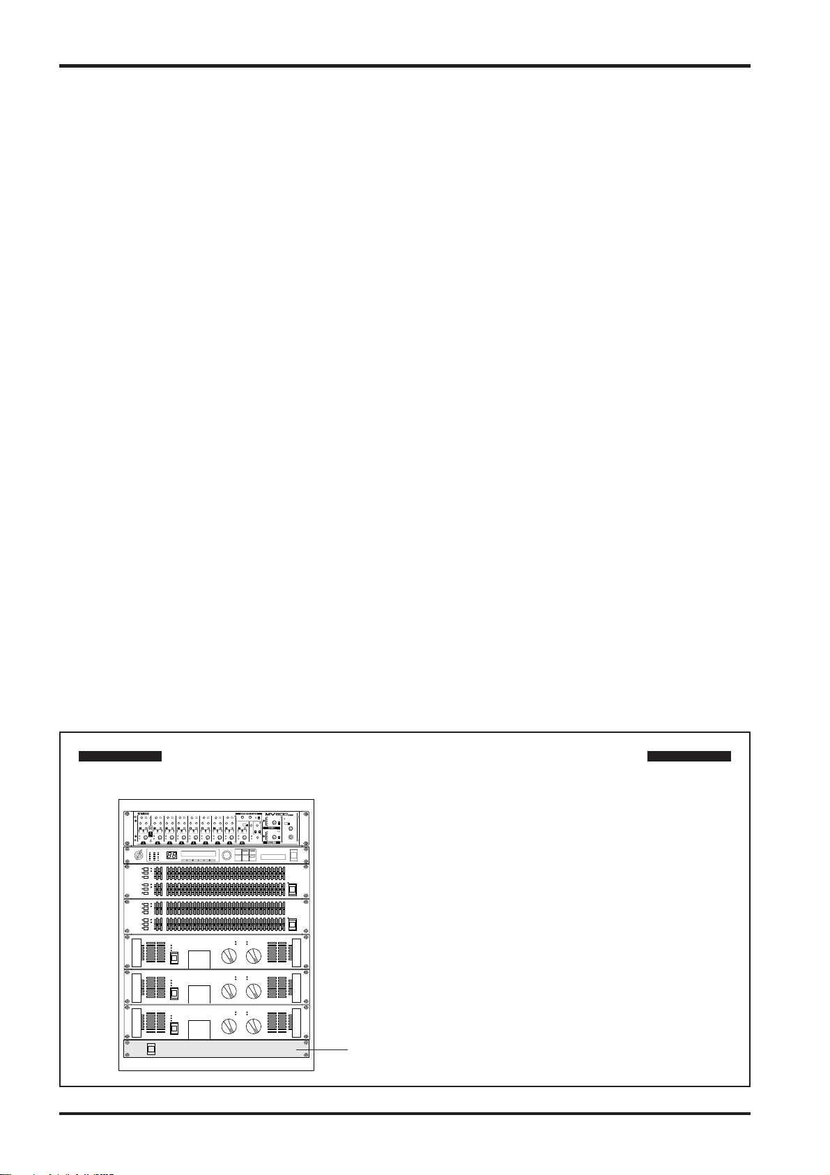
Caution: When the unit is installed in a rack
MV800 — Owner’s Manual
The main unit’s power switch is located on the rear panel of
the unit. When installed in a rack, please use the external
power switch on a power distributor, etc.
Power distributor, etc.
Front & Rear Panels
Front Panel Section
q
w
Front & Rear Panels 3
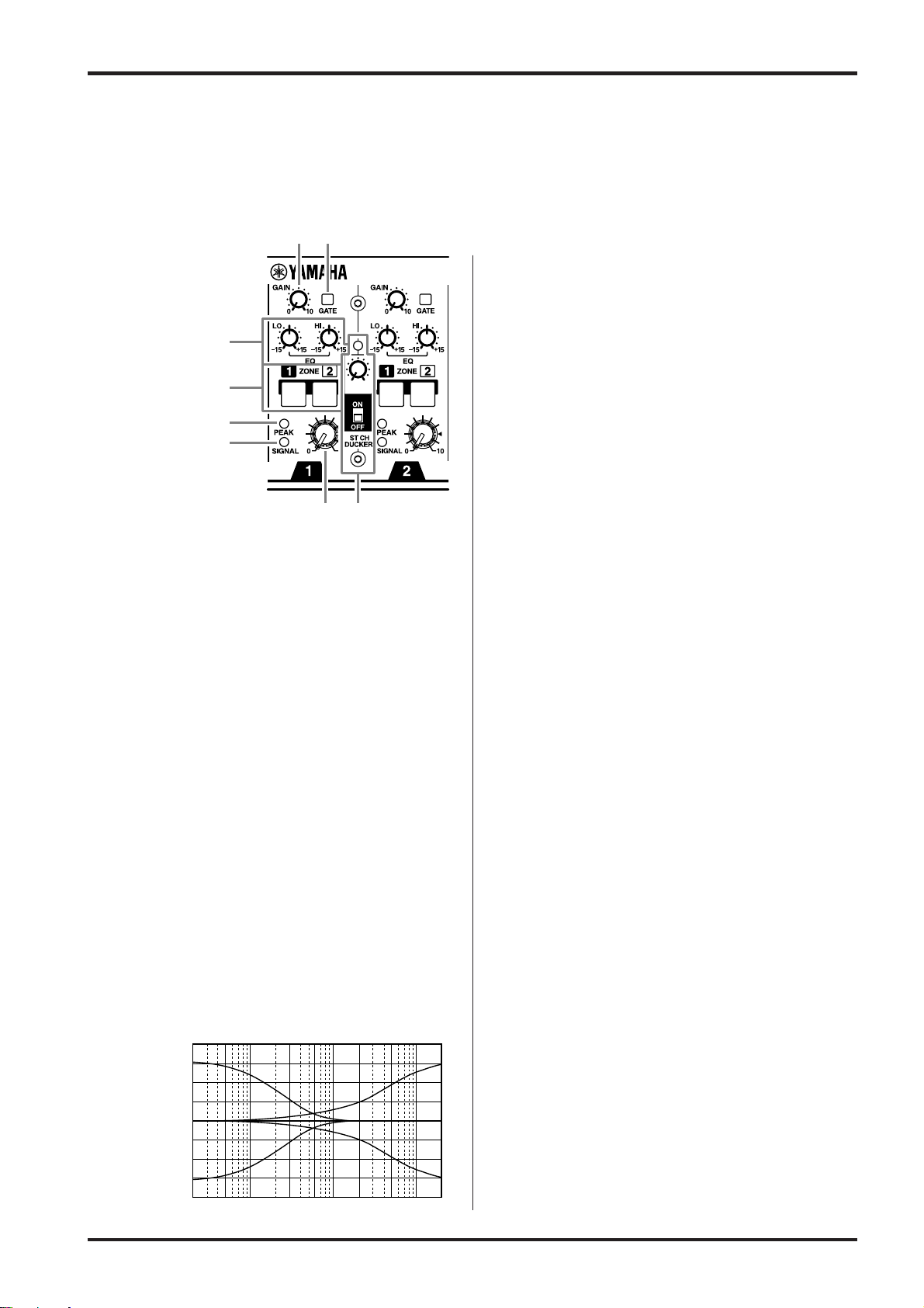
Channels 1-8
(Monaural)
e
r
t
y
ui
q GAIN Control
Adjusts the input level of the signal entering the mixer to
an optimum level.
To obtain an optimum balance between the S/N ratio
and dynamic range, adjust the level so that the PEAK
Indicator t occasionally lights.
w GATE Switch
Turns the Noise Gate ON/OFF.
When the switch is ON (>), the signal entering the
channel’s INPUT jack will only be allowed to pass
through the circuit when the designated level is exceeded. This function can be used to effectively eliminate
unwanted background noise (sounds that are lower than
the designated level). (Refer to page 9 for more information.)
* To turn the switch ON/OFF, use an insulator that is smaller
than the size of the switch.
e Equalizer
Provides +/-15dB of control over high and low frequency
ranges at the center frequencies listed below.
HIGH : 10kHz (shelving)
LOW : 100Hz (shelving)
Frequency response is flat when the knob is at its center
position.
r ZONE Select Switch
Sends each channel’s signal to the ZONE 1 bus and/or
ZONE 2 bus.
When the switch is ON (>), the signal is sent to the
relative bus.
t PEAK Indicator
The indicator detects peaks in the signal after it has
passed the EQ.
The indicator will light red when the level reaches +17dB
to warn that clipping is imminent.
y SIGNAL Indicator
The indicator lights when the signal’s level exceeds that
of the Noise Gate’s threshold level post EQ.
The light will go off shortly after the signal is cut.
u Channel Volume
Controls the output level of the channel’s signal and
adjusts the volume balance between channels.
* The volume on channels not being used should be
lowered.
i ST CH DUCKER
(Stereo Channel Ducker)
Input channels 1 and 2 are equipped with a “DUCKER
Function”.
This function automatically decreases the ST Input
signal’s volume when the signal from channel 1 or 2
exceeds the designated level. (Refer to page 9 for more
information.)
• DUCKER ON/OFF Switch
Switches the DUCKER Function ON/OFF.
• DUCKER Indicator
Lights when the DUCKER function is activated.
• DUCKER Attenuator
Sets the volume level to which the signal from the ST
input jacks will be lowered when the DUCKER
Function is operating.
Rotating the knob to the right decreases the volume.
+20
+15
+10
+5
0
–5
Response [dB]
–10
–15
–20
Frequency [Hz]
10k1k100 20k20
MV800 — Owner’s Manual
4 Front & Rear Panels
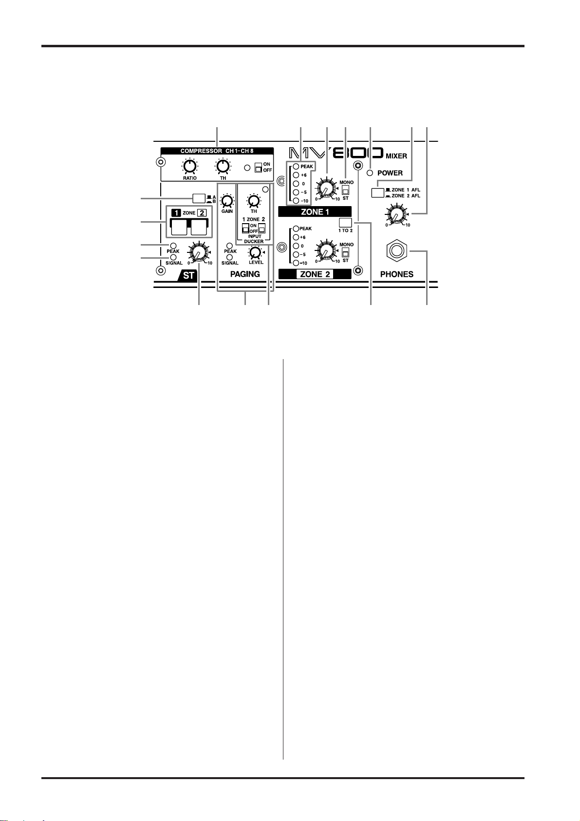
Stereo Channel & Master Control Sections
yo!0 !1 !3 !4 !5
q
w
e
r
tui !6!2
q ST Input Select Switch
Selects which of the two input signals, from ST Input
jacks A or B, will be used.
In the raised position (?), ST Input jack A is selected
while the lowered position (>) selects ST Input jack B.
w ZONE Select Switch
The same as number r on page 3.
e PEAK Indicator
Indicates peaks in the signal of the post buffer amp.
The indicator will light red when the level reaches +17dB
to warn that clipping is imminent.
r SIGNAL Indicator
The indicator will light when the signal level exceeds
-10dB in the post buffer amp.
t Channel Volume
The same as number u on page 3.
y COMPRESSOR
The COMPRESSOR controls the signal’s volume level
when the level set with the TH (Threshold) Control is
exceeded.
The Compressor is effective on input channels 1-8.
(Refer to page 9 for more information.)
• COMPRESSOR ON/OFF Switch
Switches the COMPRESSOR ON/OFF.
• COMPRESSOR Indicator
Lights when the COMPRESSOR is activated.
• TH Control
Sets the input level (Threshold level) at which the
compressor will function. Rotating the control to the
right allows the compressor to function at lower
volume levels.
• RATIO Control
Sets the ratio of compression that is applied to the
signal when it exceeds the threshold level. Rotating the
knob to the right increases the amount of compression.
When the knob is turned fully to the left, the signal
will not be compressed.
u PAGING
The PAGING function terminates all signals from each
of the INPUT channels (1-8, ST), INSERT IN and
STACK IN input jacks and only allows the signal from
the PAGING MIC/LINE input jack to be produced. This
function can also be used with a control signal from an
emergency announcement system. (Refer to page 9 for
more information.)
• PAGING GAIN Control
Controls the input sensitivity of the PAGING MIC/
LINE input jack.
An optimum balance between the S/N and dynamic
range is achieved when the PEAK indicator lights
occasionally.
• PAGING PEAK Indicator
Indicates post head amp level peaks in the PAGING
MIC/LINE signal.
The indicator will light red when the level reaches
+17dB to warn that clipping is imminent.
• PAGING SIGNAL Indicator
The indicator will light when the PAGING MIC/
LINE’s post head amp signal level exceeds -10dB.
MV800 — Owner’s Manual
Front & Rear Panels 5
• PAGING LEVEL Control
Controls the output level of the PAGING MIC/LINE
input and adjusts the volume.
i PAGING INPUT DUCKER
• PAGING TH Control
Sets the level at which the mixer switches to its
PAGING function. Rotating the knob to the right
lowers the level at which the mixer will switch to the
paging function.
• PAGING Indicator
The indicator lights when the paging function is in
use.
• PAGING ZONE Select Switch
Selects the zone to which the PAGING MIC/LINE
signal will be sent. The PAGING MIC/LINE signal is
sent to the zone output jacks (ZONE 1, 2) that are
switched ON.
o LEVEL Meter
This LED indicates the level of the output signal for each
of the ZONE output jacks (ZONE 1,2).
“0” indicates a nominal level, and the PEAK indicator
will light red to warn when clipping is imminent.
!0 ZONE Volume
Controls the volume level of the signal that is sent to the
ZONE output jacks (ZONE 1, 2).
!1 ST/MONO Select Switch
Set the switch to ST when the signal from the ST Input
jack is to be sent to the ZONE output jacks (ZONE 1, 2)
as a stereo signal. Set the switch to MONO when the L
and R channels are to be mixed as a monaural signal.
!2 ZONE 1 TO 2 Switches
Set the switch to its ON (>) position to send the signal
from ZONE 1 (pre-volume) to ZONE 2 (pre-volume). In
this case, the ZONE 1 (pre-volume) signal will be sent to
the ZONE 2 output jacks and that signal’s volume can be
adjusted with the ZONE 2 Volume control.
!3 POWER Indicator
The indicator will light when the unit’s power is ON.
!4 ZONE AFL Select Switch
Selects the signal that is sent to the PHONES jack.
Press the switch to select either ZONE 1 (?) or ZONE 2
(>).
!5 HEADPHONE Volume
Controls the signal level that is sent to the PHONES jack.
!6 PHONES Jack
This is a stereo phone type jack for connecting a pair of
headphones (nominal output/impedance of 30mW/
40Ω).
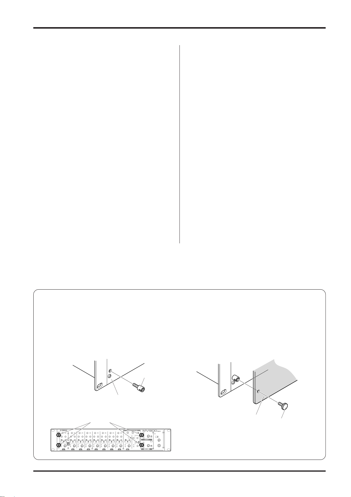
■ Attaching the Security Cover
The MV800 is supplied with a security cover for channels 1-8, the ST channel, and the compressor and paging sections. If the
security cover is needed to protect knobs and switches from being tampered with, attach the security cover after connecting
and setting up the microphones and line devices, etc.
1. Attach the post screws to the attachment holes (4
locations) on the front panel.
Post screw
Front panel
Attachment hole
2. Align the holes in the security cover with the post
screws and attach the cover with the set screws.
Security cover
Set screw
MV800 — Owner’s Manual
 Loading...