

Page 1
SOUND LIST & MIDI DATA
Page 2
TABLE OF CONTENTS
mEFFECT
A/D Input Preset 4
Effect Type List 5
Effect LSB/MSB List 8
Effect Parameter List 11
Explanation of effect parameters 23
Effect Data Assign Table 25
mMIDI
MIDI data format 28
MIDI implementation chart 60
mVOICE
EFFECTMIDIVOICE
XG Voice List 62
TG300B Voice 90
About the 128 GM sounds 102
XG Drum Map 104
TG300B Drum Map 109
Performance List 110
3
Page 3
EFFECT
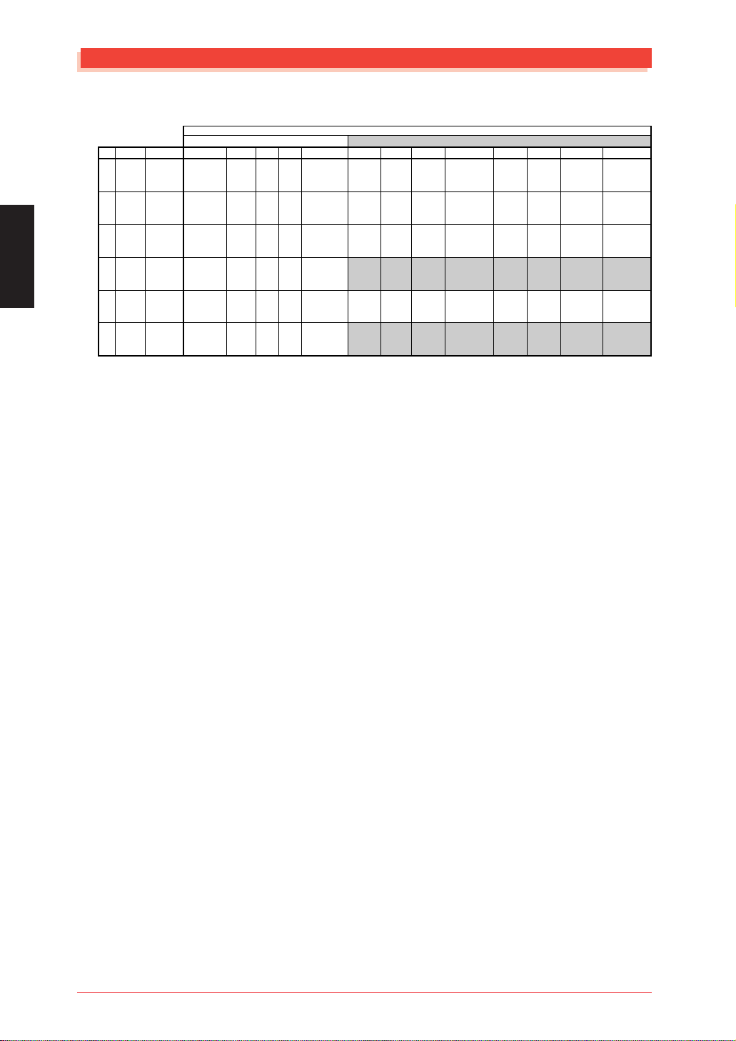
A/D Input Preset
A/D Input Preset
A/D1
BANK
Source
Preset Name
0
MIC
input gain
var type
Preset Name
GUITAR
1
input gain
(Note 1)
var type
Preset Name
KEYBOARD
2
input gain
var type
Preset Name
AUDIO
3
input gain
(Note 2)
var type
Preset Name
STEREO
18
19
input gain
KEYBOARD
var type
(Note 3)
Preset Name
STEREO
input gain
AUDIO
var type
(Note 3)
(Note 1) Depending on the guitar, the input may be distorted. Adjust the A/D INPUT
(Note 2) AUDIO sets PAN to Lch for A/D1 and Rch for A/D2.
(Note 3) The Stereo setting can be selected only for A/D1.
A/D2
PGM# = 1
Off
mic
Off
mic
Off
line
Off
line
Off
line
Off
line
-
VOLUME or the volume of your guitar.
The A/D1 and A/D2 inputs will be handled as the Lch and Rch respectively of a
stereo signal.
Thus, when you select Stereo, the bank number and program number of part A/D2
will be displayed as "***" and cannot be set.
2
Mic
mic
Guitar
mic
Keyboard
line
Audio
line
Keyboard
line
Audio
line
-
3
Reverb
mic
Reverb
mic
Reverb
line
Reverb
line
Reverb
line
Reverb
line
-
4
5
Chorus
Chorus+Reverb
mic
mic
-
-
Chorus
Chorus+Reverb
mic
mic
-
-
Chorus
Chorus+Reverb
line
line
-
-
Chorus
Chorus+Reverb
line
line
-
-
Chorus
Chorus+Reverb
line
line
-
-
Chorus
Chorus+Reverb
line
line
-
-
6
Karaoke1
mic
Karaoke1
Tube
mic
Amp Sim.
Phaser EP
line
Phaser
Phaser EP
line
Phaser
7
Karaoke2
mic
Karaoke2
Stack
mic
Amp Sim.
Pan EP
line
Auto Pan
Pan EP
line
Auto Pan
8
Karaoke3
mic
Karaoke3
Flang Gtr
mic
Flanger
Wah Clavi
line
Touch Wah
Wah Clavi
line
Touch Wah
9
Echo
mic
Echo
Clean Gtr
mic
Celeste
Rotary Orgn
line
Rotary Speaker
Rotary Orgn
line
Rotary Speaker
10
Vocal
mic
Stage1
Funk Gtr
mic
Touch Wah
Synth Str
line
Symphonic
Synth Str
line
Symphonic
11
12
Studio
Oct Up
mic
mic
HM Enhancer
Pitch Change
Tremolo
Phaser
mic
mic
Tremolo
Phaser
Synth Lead
Synth Pad
line
line
Delay LCR
Flanger2
Synth Lead
Synth Pad
line
line
Delay LCR
Flanger2
13
Oct Down
mic
Pitch Change
5th Guitar
mic
Pitch Change
SFX
line
Pitch Change
SFX
line
Pitch Change
4
MU128 EFFECT
Page 4
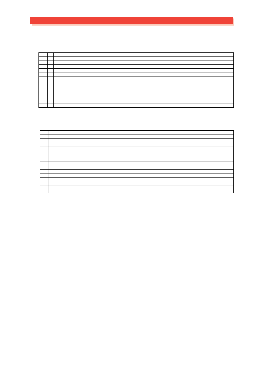
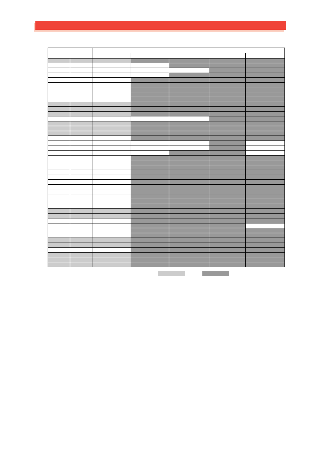
Effect Type List
REVERB
0
1
2
3
4
5
6
7
8
9
MSB
00H
01H
01H
02H
02H
02H
03H
03H
04H
10H
11H
12H
13H
MSB
00H
41H
41H
41H
41H
42H
42H
42H
42H
43H
43H
43H
44H
57H
48H
Effect Type
LSB
NO EFFECT
00H
HALL 1
00H
HALL 2
01H
ROOM 1
00H
ROOM 2
01H
ROOM 3
02H
STAGE 1
00H
STAGE 2
01H
PLATE
00H
WHITE ROOM
00H
TUNNEL
00H
CANYON
00H
BASEMENT
00H
LSB
00H
00H
01H
02H
08H
00H
01H
02H
08H
00H
01H
08H
00H
00H
00H
Effect Type
NO EFFECT
CHORUS 1
CHORUS 2
CHORUS 3
CHORUS 4
CELESTE 1
CELESTE 2
CELESTE 3
CELESTE 4
FLANGER 1
FLANGER 2
FLANGER 3
SYMPHONIC
ENSEMBLE DETUNE
PHASER 1
No.
0
1
2
3
4
5
6
7
8
9
10
11
12
CHORUS
No.
10
11
12
13
14
Effect Type List
Remarks
Turn off the effect.
Reverb simulating the acoustics of a hall.
˝
Reverb simulating the acoustics of a room.
˝
˝
Reverb appropriate for a solo instrument.
˝
Reverb simulating a metal plate reverb device.
Unique short reverb with a slight initial delay.
Simulation of a cylindrical space extending to left and right.
A hypothetical acoustic space which extends without limit.
Reverb with distinctive resonance following a slight initial delay.
Remarks
Turn off the effect.
A standard chorus effect, adding natural spaciousness to the sound.
˝
˝
˝
An effect which uses a 3-phase LFO to add modulation and spaciousness to the sound.
˝
˝
˝
An effect reminiscent of a jet airplane taking off and landing.
˝
˝
A multi-stage version of CELESTE modulation.
Chorus effect without modulation, created by adding a slightly pitch-shifted sound.
Cyclically changes the phase to modulate the sound.
MU128 EFFECT
5
Page 5
Effect Type List
VARIATION
No.
MSB
LSB
0
00H
00H
1
01H
00H
2
01H
01H
3
02H
00H
4
02H
01H
5
02H
02H
6
03H
00H
7
03H
01H
8
04H
00H
9
10H
00H
10
11H
00H
11
12H
00H
12
13H
00H
13
05H
00H
14
06H
00H
15
07H
00H
16
08H
00H
17
09H
00H
18
09H
01H
19
00H
0AH
20
00H
0BH
21
00H
14H
22
01H
14H
23
02H
14H
24
00H
41H
25
01H
41H
26
02H
41H
27
08H
41H
28
00H
42H
29
01H
42H
30
02H
42H
31
08H
42H
32
00H
43H
33
01H
43H
34
08H
43H
35
00H
44H
36
00H
57H
37
00H
58H
38
00H
45H
39
00H
56H
40
00H
46H
41
00H
47H
42
00H
48H
43
08H
48H
44
00H
49H
45
01H
49H
46
00H
4AH
47
00H
4BH
48
00H
4CH
49
00H
4DH
50
00H
4EH
51
01H
4EH
52
02H
4EH
53
00H
52H
54
01H
52H
55
02H
52H
56
08H
52H
57
00H
50H
58
01H
50H
59
00H
51H
60
00H
53H
61
00H
54H
62
00H
55H
63
00H
5DH
64
00H
5EH
65
00H
5FH
66
01H
5FH
67
00H
60H
68
01H
60H
69
00H
61H
70
01H
61H
71
00H
40H
Effect Type
NO EFFECT
HALL 1
HALL 2
ROOM 1
ROOM 2
ROOM 3
STAGE 1
STAGE 2
PLATE
WHITE ROOM
TUNNEL
CANYON
BASEMENT
DELAY L,C,R
DELAY L,R
ECHO
CROSS DELAY
ER 1
ER 2
GATE REVERB
REVERSE GATE
KARAOKE 1
KARAOKE 2
KARAOKE 3
CHORUS 1
CHORUS 2
CHORUS 3
CHORUS 4
CELESTE 1
CELESTE 2
CELESTE 3
CELESTE 4
FLANGER 1
FLANGER 2
FLANGER 3
SYMPHONIC
ENSEMBLE DETUNE
AMBIENCE
ROTARY SPEAKER
2WAY ROTARY SPEAKER
TREMOLO
AUTO PAN
PHASER 1
PHASER 2
DISTORTION
COMP+DISTORTION
OVER DRIVE
AMP SIMULATOR
3BAND EQ(MONO)
2BAND EQ(STEREO)
AUTO WAH(LFO)
AUTO WAH+DIST
AUTO WAH+ODRV
TOUCH WAH 1
TOUCH WAH 2
TOUCH WAH+DIST
TOUCH WAH+ODRV
PITCH CHANGE 1
PITCH CHANGE 2
HARMONIC ENHANCER*
COMPRESSOR
NOISE GATE
VOICE CANCEL
TALKING MODULATOR
LO-FI
DIST+DELAY
OVERDRIVE+DELAY
COMP+DIST+DELAY
COMP+OVERDRIVE+DELAY
WAH+DIST+DELAY
WAH+OVERDRIVE+DELAY
THRU
Remarks
Turns off the effect.
Reverb simulating the acoustics of a hall.
˝
Reverb simulating the acoustics of a room.
˝
˝
Reverb appropriate for a solo instrument.
˝
Reverb simulating a metal plate reverb device.
Distinctive short reverb with a slight initial delay.
Simulation of a cylindrical space extending to left and right.
A hypothetical acoustic space which extends without limit.
Reverb with distinctive resonance following a slight initial delay.
Three delay sounds L, R and C (center).
Two delay sounds L and R, with two feedback delays.
Two delays L and R, with independent feedback delay for L and R.
This effect crosses the feedback of two delays.
This effect isolates only the early reflection components of the reverb.
˝
Simulation of gated reverb.
Simulation of gated reverb played back in reverse.
Echo for karaoke.
˝
˝
Conventional chorus effect which gives natural spaciousness to the sound.
˝
˝
˝
A three-phase LFO is used to give modulation and spaciousness to the sound.
˝
˝
˝
An effect reminiscent of a jet airplane taking off and landing.
˝
˝
A multi-stage version of CELESTE modulation.
Chorus effect without modulation, created by adding a slightly pitch-shifted sound.
An effect which adds spatial breadth by blurring the location of the sound.
Simulation of a rotary speaker. AC1 (assignable controller 1) etc. can be used to control the rotation speed.
Simulation of a rotary speaker. AC1 (assignable controller 1) etc. can be used to control the rotation speed.
An effect which cyclically modulates the volume.
An effect which cyclically moves the sound between left/right and front/back.
Cyclically changes the phase to modulate the sound.
˝
Adds distortion with an edge to the sound. Since a noise gate is included, this is suitable for use with A/D input as well.
Since a compressor is included in the first stage, distortion can be applied evenly, regardless of the input level.
Adds mild distortion to the sound. Since a noise gate is included, this is suitable for A/D input as well.
Simulation of a guitar amp. Since a noise gate is included, this is suitable for use with A/D input as well.
Mono EQ with equalization of LOW, MID and HIGH.
Stereo EQ with equalization of LOW and HIGH. Ideal for Drum Parts.
Cyclically changes the center frequency of a wah filter. Can also be used with AC1 etc. as a pedal wah.
Applies DISTORTION to the output of AUTO WAH to distort the sound. Can also be used with AC1 etc. as a pedal wah.
Applies OVERDRIVE to the output of AUTO WAH to distort the sound. Can also be used with AC1 etc. as a pedal wah.
Changes the center frequency of a wah filter according to the input level. Can also be used with AC1 etc. as a pedal way.
Applies DISTORTION to the output of TOUCH WAH to distort the sound. Can also be used with AC1 etc. as a pedal wah.
Applies OVERDRIVE to the output of TOUCH WAH to distort the sound. Can also be used with AC1 etc. as a pedal wah.
Changes the center frequency of a wah filter according to the input level. Can also be used with AC1 etc. as a pedal wah.
This effect changes the pitch of the input signal.
˝
This effect adds new overtones to the input signal to make the sound stand out.
Holds down the output when the input exceeds a specified level. Can also be used to add a sense of attack to the sound.
Gates the input when the input signal falls below a specified level. Useful for cutting noise from the A/D input, etc.
Attenuates the vocal part from sources such as CDs.
Adds a vowel sound to the input signal.
Degrades the audio quality of the input signal.
DISTORTION and DELAY are connected in series.
OVERDRIVE and DELAY are connected in series.
COMPRESSOR, DISTORTION and DELAY are connected in series.
COMPRESSOR, OVERDRIVE and DELAY are connected in series.
TOUCH WAH, DISTORTION and DELAY are connected in series.
TOUCH WAH, OVERDRIVE and DELAY are connected in series.
Bypass without applying an effect.
* The Harmonic Enhancer produces the same effect as its MU series predecessor.
6
MU128 EFFECT
Page 6
INSERTION1,2
No.
0
1
2
3
4
5
6
7
8
9
10
11
12
13
14
15
16
17
18
19
20
21
22
23
24
25
26
27
28
29
30
31
32
33
34
35
36
37
38
39
40
41
42
43
Effect Type
MSB
LSB
THRU
00H
40H
HALL 1
00H
01H
HALL 2
01H
01H
ROOM 1
00H
02H
ROOM 2
01H
02H
ROOM 3
02H
02H
STAGE 1
00H
03H
STAGE 2
01H
03H
PLATE
00H
04H
DELAY L,C,R
00H
05H
DELAY L,R
00H
06H
ECHO
00H
07H
CROSS DELAY
00H
08H
KARAOKE 1
00H
14H
KARAOKE 2
01H
14H
KARAOKE 3
02H
14H
CHORUS 1
00H
41H
CHORUS 2
01H
41H
CHORUS 3
02H
41H
CHORUS 4
08H
41H
CELESTE 1
00H
42H
CELESTE 2
01H
42H
CELESTE 3
02H
42H
CELESTE 4
08H
42H
FLANGER 1
00H
43H
FLANGER 2
01H
43H
FLANGER 3
08H
43H
SYMPHONIC
00H
44H
ENSEMBLE DETUNE
00H
57H
ROTARY SPEAKER
00H
45H
TREMOLO
00H
46H
AUTO PAN
00H
47H
PHASER 1
00H
48H
DISTORTION
00H
49H
OVER DRIVE
00H
4AH
AMP SIMULATOR
00H
4BH
3BAND EQ(MONO)
00H
4CH
2BAND EQ(STEREO)
00H
4DH
AUTO WAH(LFO)
00H
4EH
TOUCH WAH 1
00H
52H
TOUCH WAH 2
08H
52H
HARMONIC ENHANCER*
00H
51H
COMPRESSOR
00H
53H
NOISE GATE
00H
54H
Effect Type List
Remarks
Bypass without applying an effect.
Reverb simulating the acoustics of a hall.
˝
Reverb simulating the acoustics of a room.
˝
˝
Reverb appropriate for a solo instrument.
˝
Reverb simulating a metal plate reverb device.
Three delay sounds L, R and C (center).
Two delay sounds L and R, with two feedback delays.
Two delays L and R, with independent feedback delay for L and R.
This effect crosses the feedback of two delays.
Echo for karaoke.
˝
˝
Conventional chorus effect which gives natural spaciousness to the sound.
˝
˝
˝
A three-phase LFO is used to give modulation and spaciousness to the sound.
˝
˝
˝
An effect reminiscent of a jet airplane taking off and landing.
˝
˝
A multi-stage version of CELESTE modulation.
Chorus effect without modulation, created by adding a slightly pitch-shifted sound.
Simulation of a rotary speaker. AC1 (assignable controller 1) etc. can be used to control the rotation speed.
An effect which cyclically modulates the volume.
An effect which cyclically moves the sound between left/right and front/back.
Cyclically changes the phase to modulate the sound.
Adds distortion with an edge to the sound.
Adds mild distortion to the sound.
Simulation of a guitar amp.
Mono EQ with equalization of LOW, MID and HIGH.
Stereo EQ with equalization of LOW and HIGH. Ideal for Drum Parts.
Cyclically changes the center frequency of a wah filter. Can also be used with AC1 etc. as a pedal wah.
Changes the center frequency of a wah filter according to the input level. Can also be used with AC1 etc. as a pedal wah.
Changes the center frequency of a wah filter according to the input level. Can also be used with AC1 etc. as a pedal wah.
This effect adds new overtones to the input signal to make the sound stand out.
Holds down the output when the input exceeds a specified level. Can also be used to add a sense of attack to the sound.
Gates the input when the input signal falls below a specified level. Useful for cutting noise from the A/D input, etc.
* The Harmonic Enhancer produces the same effect as its MU series predecessor.
MU128 EFFECT
7
Page 7
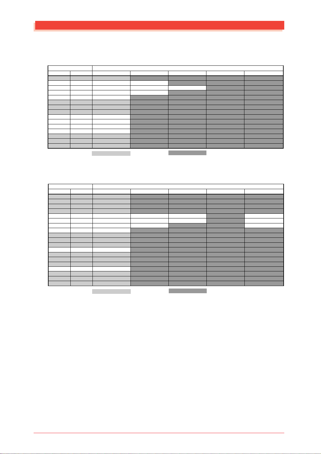
Effect LSB/MSB List
Effect LSB/MSB List
REVERB TYPE
TYPE MSB TYPE LSB
DEC HEX 00 01 02 ... 08
000 0 NO EFFECT
001 1 HALL 1 HALL 2
002 2 ROOM 1 ROOM 2 ROOM 3
003 3 STAGE 1 STAGE 2
004 4 PLATE
005 5 NO EFFECT
: : :
015 F NO EFFECT
016 10 WHITE ROOM
017 11 TUNNEL
018 12 CANYON
019 13 BASEMENT
020 14 NO EFFECT
: : :
127 7F NO EFFECT
NO EFFECT Same as basic effects (LSB=00)
CHORUS TYPE
TYPE MSB TYPE LSB
DEC HEX 00 01 02 ... 08
000 0 NO EFFECT
001 1 NO EFFECT
: : :
064 40 NO EFFECT
065 41 CHORUS 1 CHORUS 2 CHORUS 3 CHORUS 4
066 42 CELESTE 1 CELESTE 2 CELESTE 3 CELESTE 4
067 43 FLANGER 1 FLANGER 2 FLANGER 3
068 44 SYMPHONIC
069 45 NO EFFECT
: : :
071 47 NO EFFECT
072 48 PHASER 1
073 49 NO EFFECT
: : :
086 56 NO EFFECT
087 57 ENSEMBLE DETUNE
088 58 NO EFFECT
: : :
127 7F NO EFFECT
NO EFFECT Same as basic effects (LSB=00)
8
MU128 EFFECT
Page 8
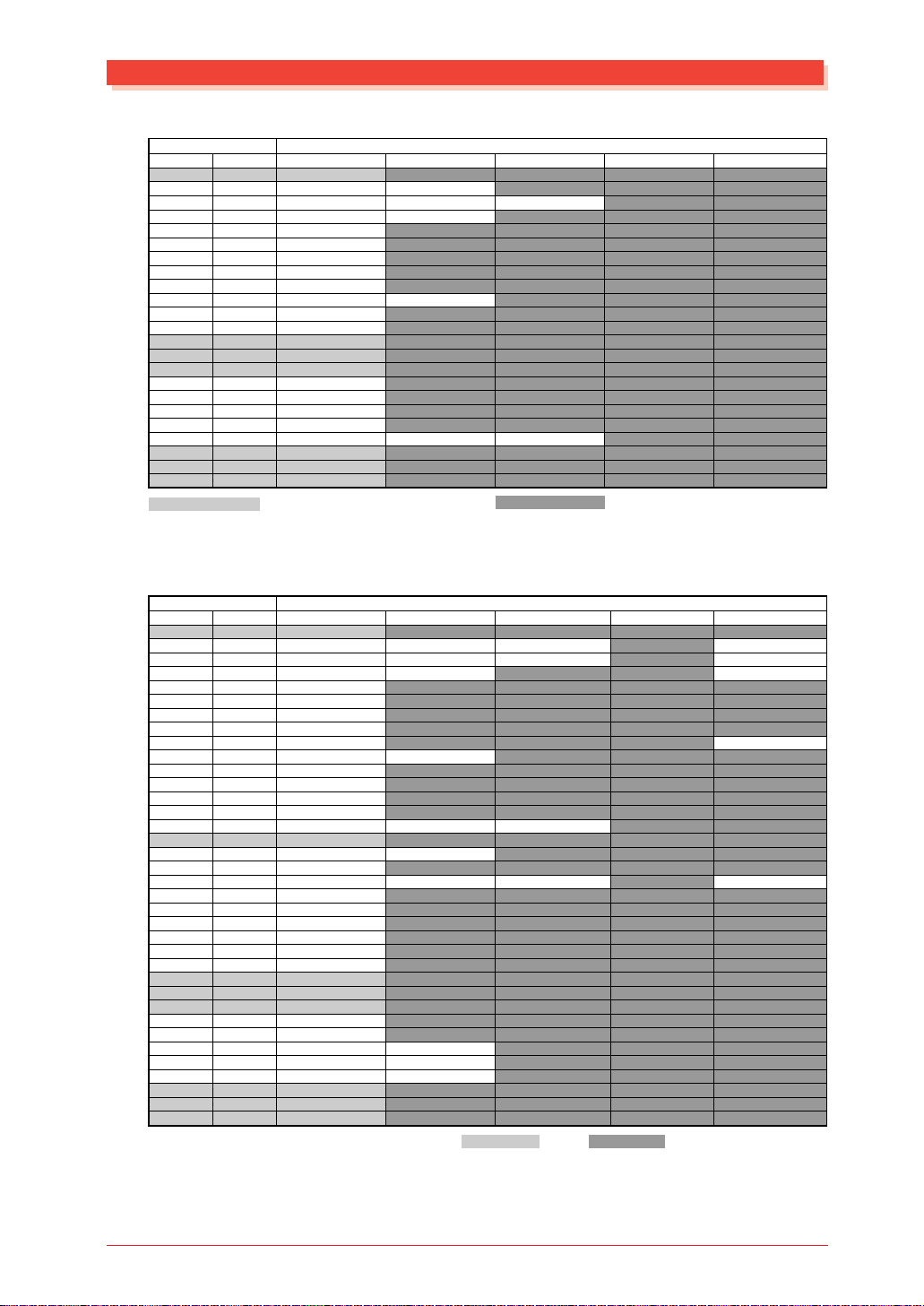
Effect LSB/MSB List
VARIATION TYPE (MSB=0 - 63)
TYPE MSB TYPE LSB
DEC HEX 00 01 02 ... 08
000 0 NO EFFECT
001 1 HALL 1 HALL 2
002 2 ROOM 1 ROOM 2 ROOM 3
003 3 STAGE 1 STAGE 2
004 4 PLATE
005 5 DELAY L,C,R
006 6 DELAY L,R
007 7 ECHO
008 8 CROSS DELAY
009 9 ER 1 ER 2
010 A GATE REVERB
011 B REVERSE GATE
012 C NO EFFECT or THRU
: : :
015 F NO EFFECT or THRU
016 10 WHITE ROOM
017 11 TUNNEL
018 12 CANYON
019 13 BASEMENT
020 14 KARAOKE 1 KARAOKE 2 KARAOKE 3
021 15 NO EFFECT or THRU
: : :
063 3F NO EFFECT or THRU
NO EFFECT (for SYS) or THRU (for INS) Same as basic effects (LSB=00)
VARIATION TYPE (MSB=64 - 127)
TYPE MSB TYPE LSB
DEC HEX 00 01 02 ... 08
064 40 THRU
065 41 CHORUS 1 CHORUS 2 CHORUS 3 CHORUS 4
066 42 CELESTE 1 CELESTE 2 CELESTE 3 CELESTE 4
067 43 FLANGER 1 FLANGER 2 FLANGER 3
068 44 SYMPHONIC
069 45 ROTARY SPEAKER
070 46 TREMOLO
071 47 AUTO PAN
072 48 PHASER 1 PHASER 2
073 49 DISTORTION COMP+DISTOR TION
074 4A OVER DRIVE
075 4B AMP SIMULATOR
076 4C 3-BAND EQ
077 4D 2-BAND EQ
078 4E AUT O W AH(LFO) AUTO W AH+DIST
079 4F THRU
080 50 PITCH CHANGE1 PITCH CHANGE2
081 51
082 52 TOUCH WAH 1 TOUCH WAH+DIST
083 53 COMPRESSOR
084 54 NOISE GATE
085 55 VOICE CANCEL
086 56 2
087 57
088 58 AMBIENCE
089 59 THRU
: : :
092 5C THRU
093 5D
094 5E LO-FI
095 5F DIST+DELAY
096 60
097 61 WAH+DIST+DELAY
098 62 THRU
: : :
127 7F THRU
* The Harmonic Enhancer produces the same effect as its MU series predecessor.
HARMONIC ENHANCER*
WA Y RO TARY SPEAKER
ENSEMBLE DETUNE
T ALKING MODULATOR
COMP+DIST+DELAY
OVERDRIVE+DELAY
COMP+OVERDRIVE+DELA Y
WAH+OVERDRIVE+DELAY
AUTO W AH+OVERDRIVE
TOUCH WAH+O VERDRIVE
THRU
TOUCH WAH 2
Same as basic effects (LSB=00)
MU128 EFFECT
9
Page 9
Effect LSB/MSB List
INSERTION TYPE
TYPE MSB TYPE LSB
DEC HEX 00 01 02 ... 08
000 0 THRU
001 1 HALL 1 HALL 2
002 2 ROOM 1 ROOM 2 ROOM 3
003 3 STAGE 1 STAGE 2
004 4 PLATE
005 5 DELAY L,C,R
006 6 DELAY L,R
007 7 ECHO
008 8 CROSS DELAY
009 9 THRU
: : :
019 13 THRU
020 14 KARAOKE 1 KARAOKE 2 KARAOKE 3
021 15 THRU
: : :
063 3F THRU
064 40 THRU
065 41 CHORUS 1 CHORUS 2 CHORUS 3 CHORUS 4
066 42 CELESTE 1 CELESTE 2 CELESTE 3 CELESTE 4
067 43 FLANGER 1 FLANGER 2
068 44 SYMPHONIC
069 45 ROTARY SPEAKER
070 46 TREMOLO
071 47 AUTO PAN
072 48 PHASER 1
073 49 DISTORTION
074 4A OVER DRIVE
075 4B AMP SIMULATOR
076 4C 3BAND EQ
077 4D 2-BAND EQ
078 4E AUTO WAH(LFO)
079 4F THRU
080 50 THRU
081 51
082 52 TOUCH WAH 1 TOUCH WAH 2
083 53 COMPRESSOR
084 54 NOISE GATE
085 55 THRU
086 56 THRU
087 57
088 58 THRU
: : :
* The Harmonic Enhancer produces the same effect as its MU series predecessor.
FLANGER 3
HARMONIC ENHANCER*
ENSEMBLE DETUNE
THRU
Same as basic effects (LSB=00)
10
MU128 EFFECT
Page 10
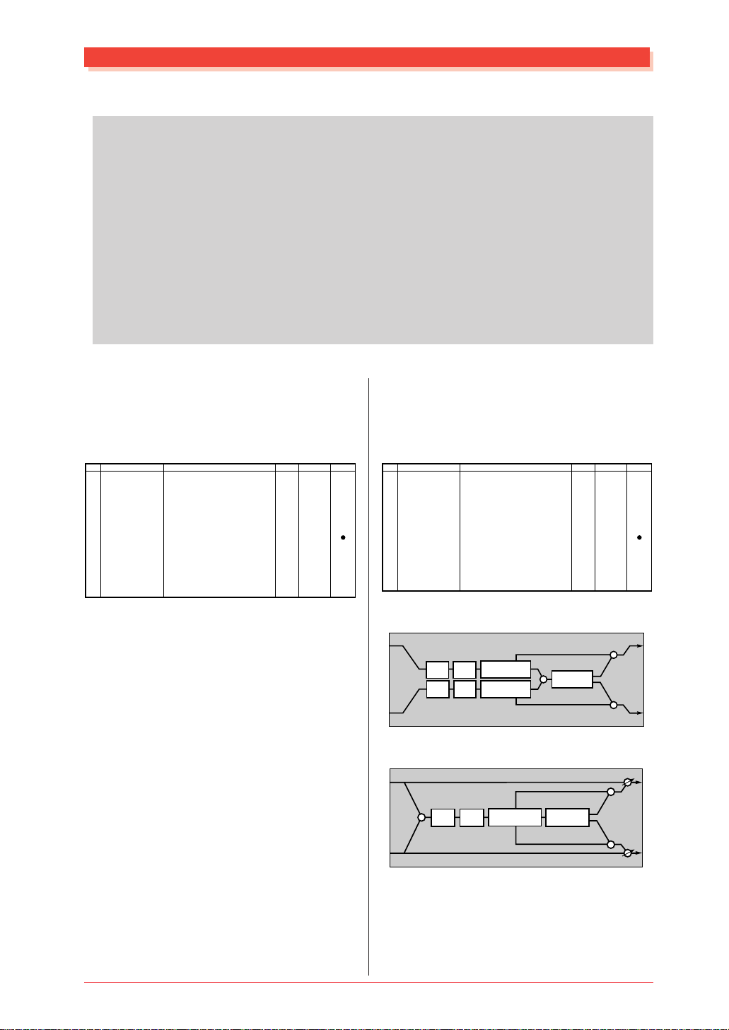
Effect Parameter List
Effect Parameter List
Note
• Parameters marked with a ● in the "Control" column can be controlled from an AC1 (assignable controller 1) etc. However, this is valid only for a Variation effect (when selected for Insertion) and for Insertion effects 1/2.
• Dry/Wet is valid only for a Variation effect (when selected for Insertion) and for Insertion effects
1/2.
• Abbreviations used in the effect block diagrams
LPF = Low Pass Filter
HPF = High Pass Filter
LSF = Low Shelving Filter
HSF = High Shelving Filter
PDF = Peak Dip Filter
EF = Envelope Follower
ER = Early Reflection
● HALL1, 2
ROOM1, 2, 3
STAGE1, 2
PLATE (Reverb, Variation, Insertion1, 2 block)
No.
1
2
3
4
5
6
7
8
9
10
11
12
13
14
15
16
Parameter
Reverb Time
Diffusion
Initial Delay
HPF Cutoff
LPF Cutoff
Dry/Wet
Rev Delay
Density
Er/Rev Balance
High Damp
Feedback Level
Display
0.3 – 30.0s
0 – 10
0 – 63
Thru – 8.0kHz
1.0k – Thru
D63>W – D=W – D<W63
0 – 63
0 – 4 (reverb, variation block)
0 – 2 (insertion1,2 block)
E63>R – E=R – E<R63
0.1 – 1.0
-63 – +63
0-69
0-10
0-63
0-52
34-60
1-127
0-63
0-4
0-2
1-127
1-10
1-127
See Table
table#4
table#5
table#3
table#3
table#5
WHITE ROOM
TUNNEL
CANYON
BASEMENT (Reverb, Variation block)
ControlValue
No.
1
2
3
4
5
6
7
8
9
10
11
12
13
14
15
16
Parameter
Reverb Time
Diffusion
Initial Delay
HPF Cutoff
LPF Cutoff
Width
Heigt
Depth
Wall Vary
Dry/Wet
Rev Delay
Density
Er/Rev Balance
High Damp
Feedback Level
Display
0.3 – 30.0s
0 – 10
0 – 63
Thru – 8.0kHz
1.0k – Thru
0.5 – 10.2m
0.5 – 20.2m
0.5 – 30.2m
0 – 30
D63>W – D=W – D<W63
0 – 63
0 – 4
E63>R – E=R – E<R63
0.1 – 1.0
-63 – +63
0-69
0-10
0-63
0-52
34-60
0-37
0-73
0-104
0-30
1-127
0-63
0-4
1-127
1-10
1-127
See Table
table#4
table#5
table#3
table#3
table#11
table#11
table#11
table#5
ControlValue
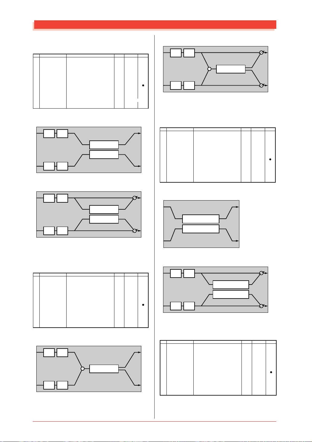
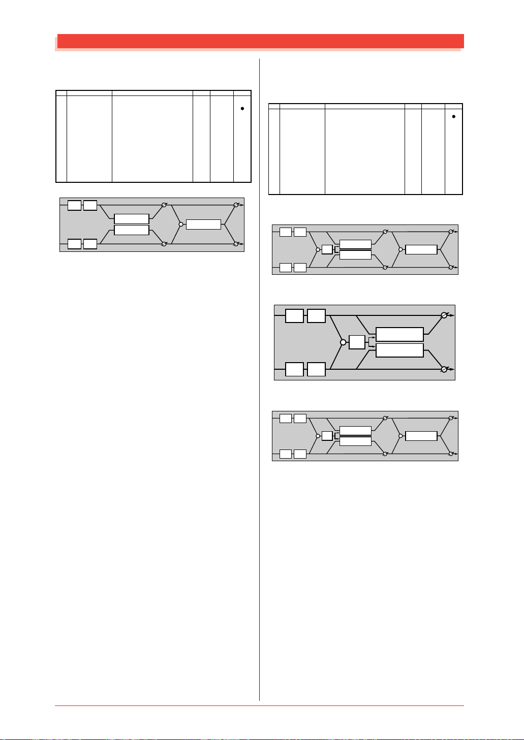
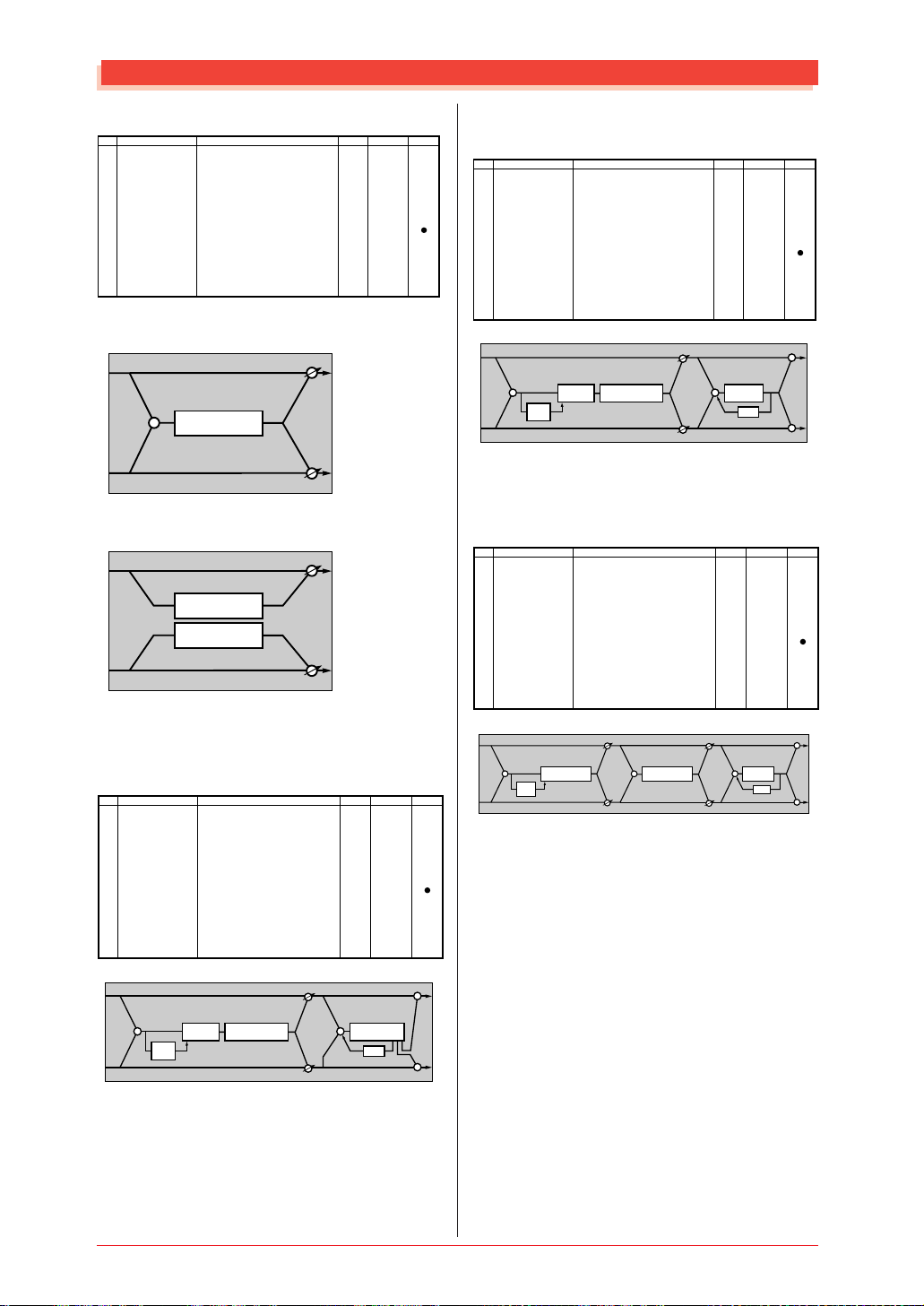
Reverb Block
L
HPF LPF
HPF LPF
DELAY/ER
DELAY/ER
+
REV
R
L
+
+
R
Variation, Insertion Block
L
dry (L)
L
+
R
MU128 EFFECT
+
HPF LPF
DELAY/ER
REV
dry (R)
+
R
11
Page 11
Effect Parameter List
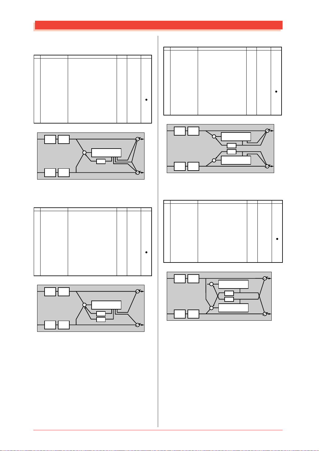
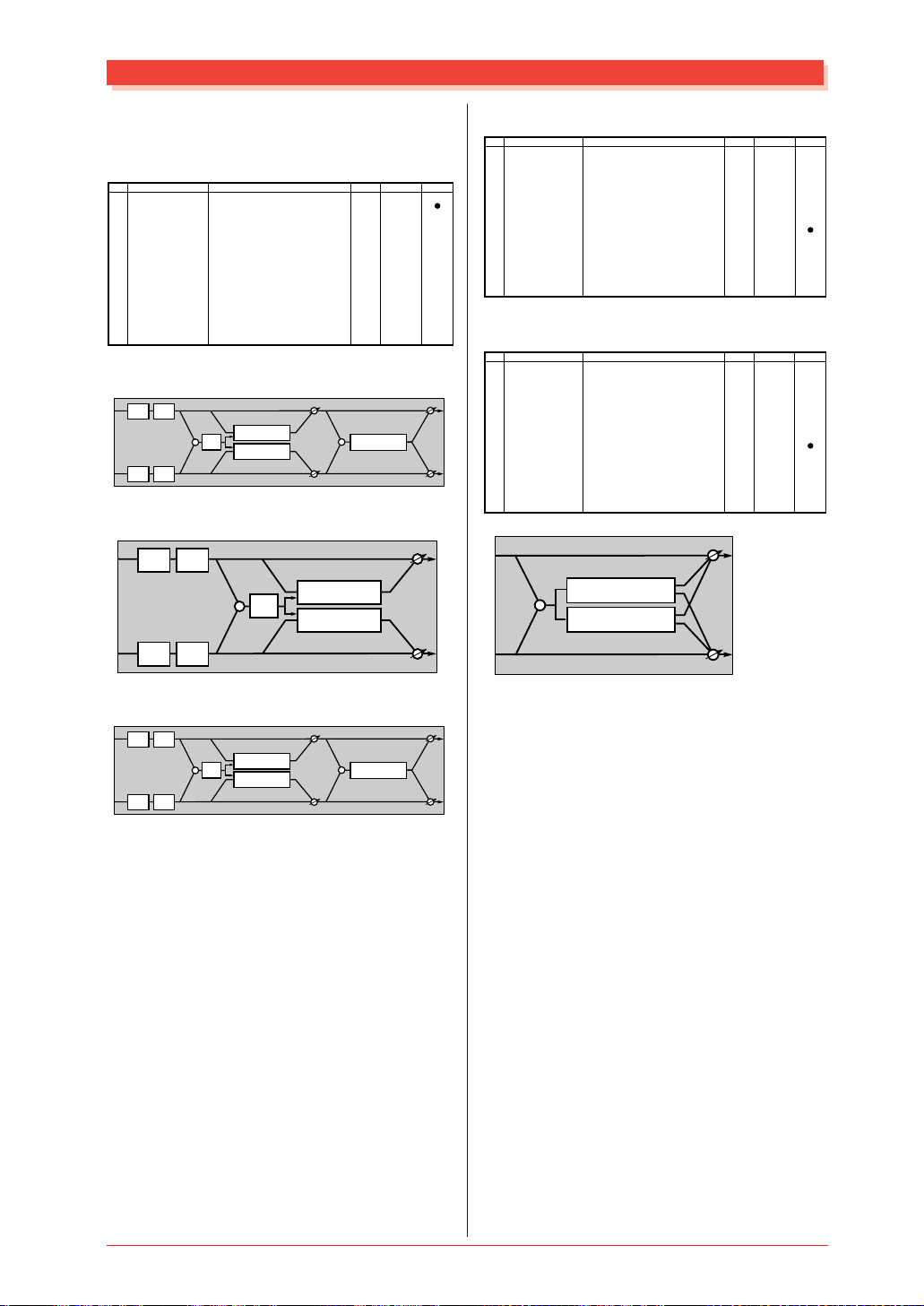
● DELAY L, C, R
(Variation, Insertion 1, 2 block)
No.
Parameter
1
Lch Delay
2
Rch Delay
3
Cch Delay
4
Feedback Delay
5
Feedback Level
6
Cch Level
7
High Damp
8
9
10
Dry/Wet
11
12
13
EQ Low Frequency
14
EQ Low Gain
15
EQ High Frequency
16
EQ High Gain
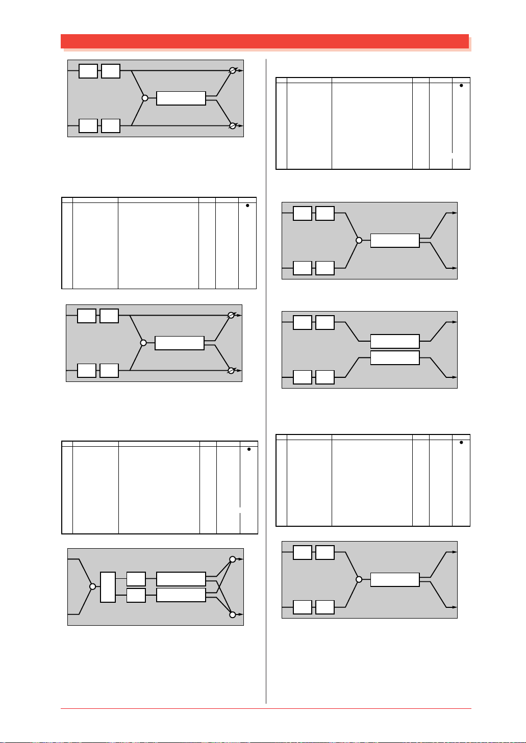
L
R
LSF HSF
LSF HSF
Display
0.1 – 1486.0ms (variation block)
0.1 – 742.9ms (insertion1,2 block)
0.1 – 1486.0ms (variation block)
0.1 – 742.9ms (insertion1,2 block)
0.1 – 1486.0ms (variation block)
0.1 – 742.9ms (insertion1,2 block)
0.1 – 1486.0ms (variation block)
0.1 – 742.9ms (insertion1,2 block)
-63 – +63
0 – 127
0.1 – 1.0
D63>W – D=W – D<W63
32Hz – 2.0kHz
-12 – +12dB
500Hz – 16.0kHz
-12 – +12dB
+
DELAY
LPF
1-14860
1-7429
1-14860
1-7429
1-14860
1-7429
1-14860
1-7429
1-127
0-127
1-10
1-127
4-40
52-76
28-58
52-76
See Table
table#3
table#3
dry (L)
L
R
dry (R)
ControlValue
L
C
R
● DELAY L, R (Variation, Insertion 1, 2 block)
No.
Parameter
1
Lch Delay
2
Rch Delay
3
Feedback Delay 1
4
Feedback Delay 2
5
Feedback Level
6
High Damp
7
8
9
10
Dry/Wet
11
12
13
EQ Low Frequency
14
EQ Low Gain
15
EQ High Frequency
16
EQ High Gain
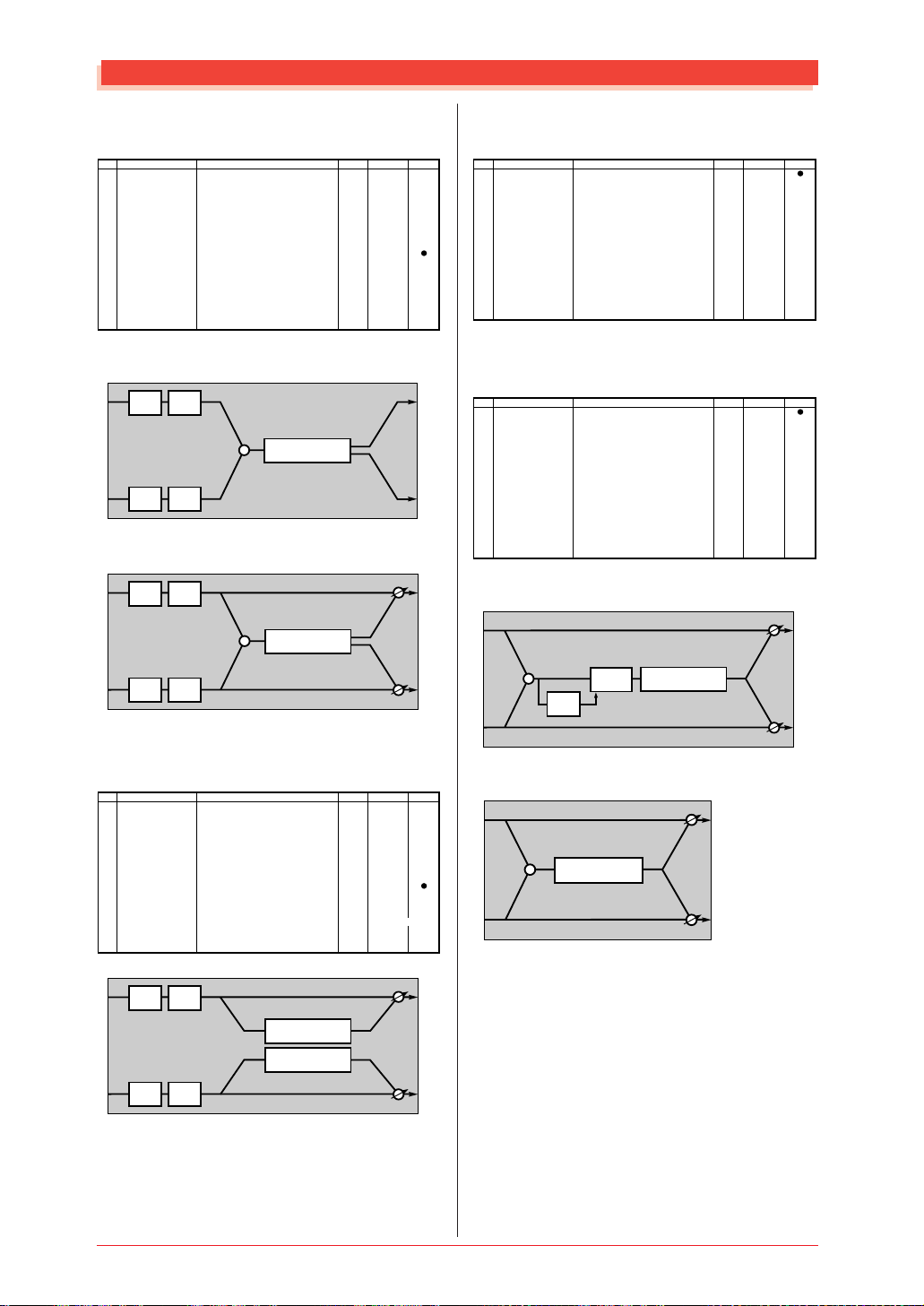
L
R
LSF HSF
LSF HSF
Display
0.1 – 1486.0ms (variation block)
0.1 – 742.9ms (insertion1,2 block)
0.1 – 1486.0ms (variation block)
0.1 – 742.9ms (insertion1,2 block)
0.1 – 1486.0ms (variation block)
0.1 – 742.9ms (insertion1,2 block)
0.1 – 1486.0ms (variation block)
0.1 – 742.9ms (insertion1,2 block)
-63 – +63
0.1 – 1.0
D63>W – D=W – D<W63
32Hz – 2.0kHz
-12 – +12dB
500Hz – 16.0kHz
-12 – +12dB
+
DELAY
LPF
LPF
1-14860
1-7429
1-14860
1-7429
1-14860
1-7429
1-14860
1-7429
1-127
1-10
1-127
4-40
52-76
28-58
52-76
See Table
table#3
table#3
dry (L)
L
R
dry (R)
ControlValue
L
R
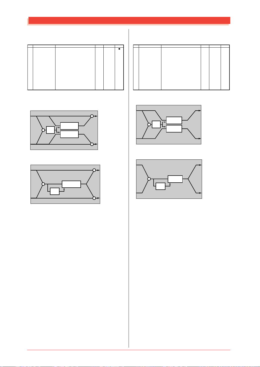
● ECHO (Variation, Insertion 1, 2 block)
No.
Parameter
1
Lch Delay1
2
Lch Feedback Level
3
Rch Delay1
4
Rch Feedback Level
5
High Damp
6
Lch Delay2
7
Rch Delay2
8
Delay2 Level
9
10
Dry/Wet
11
12
13
EQ Low Frequency
14
EQ Low Gain
15
EQ High Frequency
16
EQ High Gain
L
LSF HSF
Display
0.1 – 743.0ms (variation block)
0.1 – 371.4ms (insertion1,2 block)
-63 – +63
0.1 – 743.0ms (variation block)
0.1 – 371.4ms (insertion1,2 block)
-63 – +63
0.1 – 1.0
0.1 – 743.0ms (variation block)
0.1 – 371.4ms (insertion1,2 block)
0.1 – 743.0ms (variation block)
0.1 – 371.4ms (insertion1,2 block)
0 – 127
D63>W – D=W – D<W63
32Hz – 2.0kHz
-12 – +12dB
500Hz – 16.0kHz
-12 – +12dB
+
DELAY
1-7430
1-3714
1-127
1-7430
1-3714
1-127
1-10
1-7430
1-3714
1-7430
1-3714
0-127
1-127
4-40
52-76
28-58
52-76
See Table
table#3
table#3
dry (L)
LPF
LPF
+
R
LSF HSF
DELAY
dry (R)
● CROSS DELAY
(Variation, Insertion 1, 2 block)
No.
Parameter
1
L->R Delay
2
R->L Delay
3
Feedback Level
4
Input Select
5
High Damp
6
7
8
9
10
Dry/Wet
11
12
13
EQ Low Frequency
14
EQ Low Gain
15
EQ High Frequency
16
EQ High Gain
L
R
LSF HSF
LSF HSF
Display
0.1 – 743.0ms (variation block)
0.1 – 371.4ms (insertion1,2 block)
0.1 – 743.0ms (variation block)
0.1 – 371.4ms (insertion1,2 block)
-63 – +63
L,R,L&R
0.1 – 1.0
D63>W – D=W – D<W63
32Hz – 2.0kHz
-12 – +12dB
500Hz – 16.0kHz
-12 – +12dB
+
DELAY
LPF
LPF
+
DELAY
1-7430
1-3714
1-7430
1-3714
1-127
0-2
1-10
1-127
4-40
52-76
28-58
52-76
See Table
table#3
table#3
dry (L)
dry (R)
ControlValue
L
R
ControlValue
L
R
12
MU128 EFFECT
Page 12
Effect Parameter List
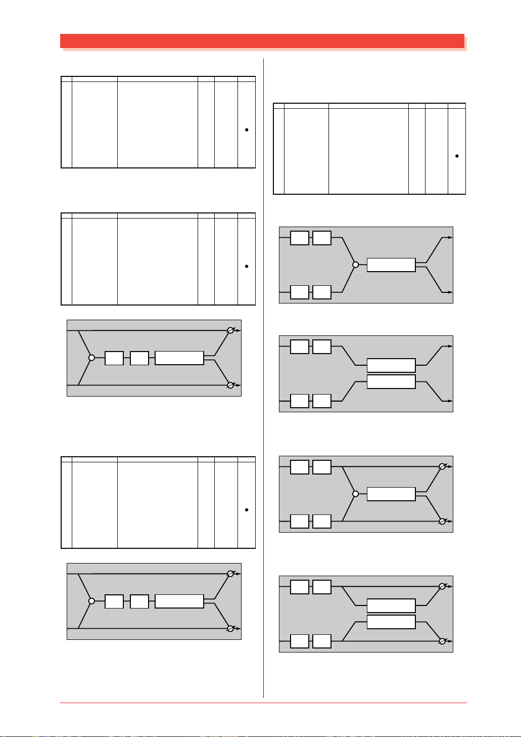
● EARLY REF 1, 2 (Variation block)
No.
1
2
3
4
5
6
7
8
9
10
11
12
13
14
15
16
Parameter
Type
Room Size
Diffusion
Initial Delay
Feedback Level
HPF Cutoff
LPF Cutoff
Dry/Wet
Liveness
Density
High Damp
Display
S-H, L-H, Rdm, Rvs, Plt, Spr
0.1 – 7.0
0 – 10
0 – 63
-63 – +63
Thru – 8.0kHz
1.0k – Thru
D63>W – D=W – D<W63
0 – 10
0 – 3
0.1 – 1.0
0-5
0-44
0-10
0-63
1-127
0-52
34-60
1-127
0-10
0-3
1-10
GATE REVERB
REVERSE GATE (Variation block)
No.
10
11
12
13
14
15
16
L
R
Parameter
1
Type
2
Room Size
3
Diffusion
4
Initial Delay
5
Feedback Level
6
HPF Cutoff
7
LPF Cutoff
8
9
Dry/Wet
Liveness
Density
High Damp
+
Display
TypeA,TypeB
0.1 – 20.0
0 – 10
0 – 127
-63 – +63
Thru – 8.0kHz
1.0k – Thru
D63>W – D=W – D<W63
0 – 10
0 – 3
0.1 – 1.0
HPF LPF
ER
0-1
0-127
0-10
0-127
1-127
0-52
34-60
1-127
0-10
0-3
1-10
dry (L)
dry (R)
See Table
table#6
table#5
table#3
table#3
See Table
table#6
table#5
table#3
table#3
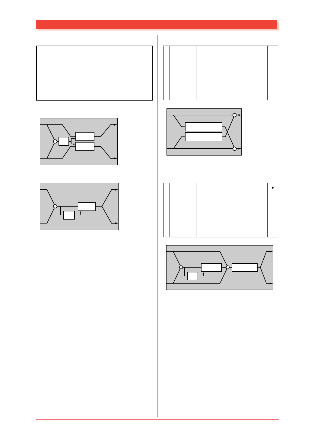
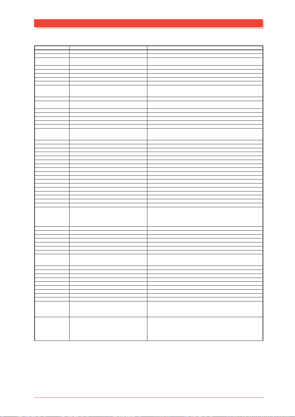
● CHORUS 1, 2, 3, 4
ControlValue
CELESTE 1, 2, 3, 4 (Chorus, Variation,
Insertion 1, 2 block)
No.
Parameter
1
LFO Frequency
2
LFO Depth
3
Feedback Level
4
Delay Offset
5
6
EQ Low Frequency
7
EQ Low Gain
8
EQ High Frequency
9
EQ High Gain
10
Dry/Wet
11
EQ Mid Frequency
12
EQ Mid Gain
13
EQ Mid Width
14
15
Input Mode
16
ControlValue
Chorus Block: when input mode = "mono"
L
LSF HSF
R
LSF HSF
Display
0.00Hz – 39.7Hz
0 – 127
-63 – +63
0 – 127
32Hz – 2.0kHz
-12 – +12dB
500Hz – 16.0kHz
-12 – +12dB
D63>W – D=W – D<W63
100Hz – 10.0kHz (variation block)
-12 – +12dB (variation block)
1.0 – 12.0 (variation block)
mono/stereo
+
CHORUS
0-127
0-127
1-127
0-127
4-40
52-76
28-58
52-76
1-127
14-54
52-76
10-120
0-1
See Table
table#1
table#2
table#3
table#3
table#3
ControlValue
L
R
Chorus Block: when input mode = "stereo"
L
L
LSF HSF
CHORUS
R
R
LSF HSF
CHORUS
L
R
● KARAOKE1, 2, 3 (Variation, Insertion 1, 2
block)
No.
10
11
12
13
14
15
16
L
R
Parameter
1
Delay Time
2
Feedback Level
3
HPF Cutoff
4
LPF Cutoff
5
6
7
8
9
Dry/Wet
+
Display
0 – 127
-63 – +63
Thru – 8.0kHz
1.0k – Thru
D63>W – D=W – D<W63
HPF LPF
KARAOKE
0-127
1-127
0-52
34-60
1-127
dry (L)
dry (R)
See Table
table#7
table#3
table#3
ControlValue
L
R
MU128 EFFECT
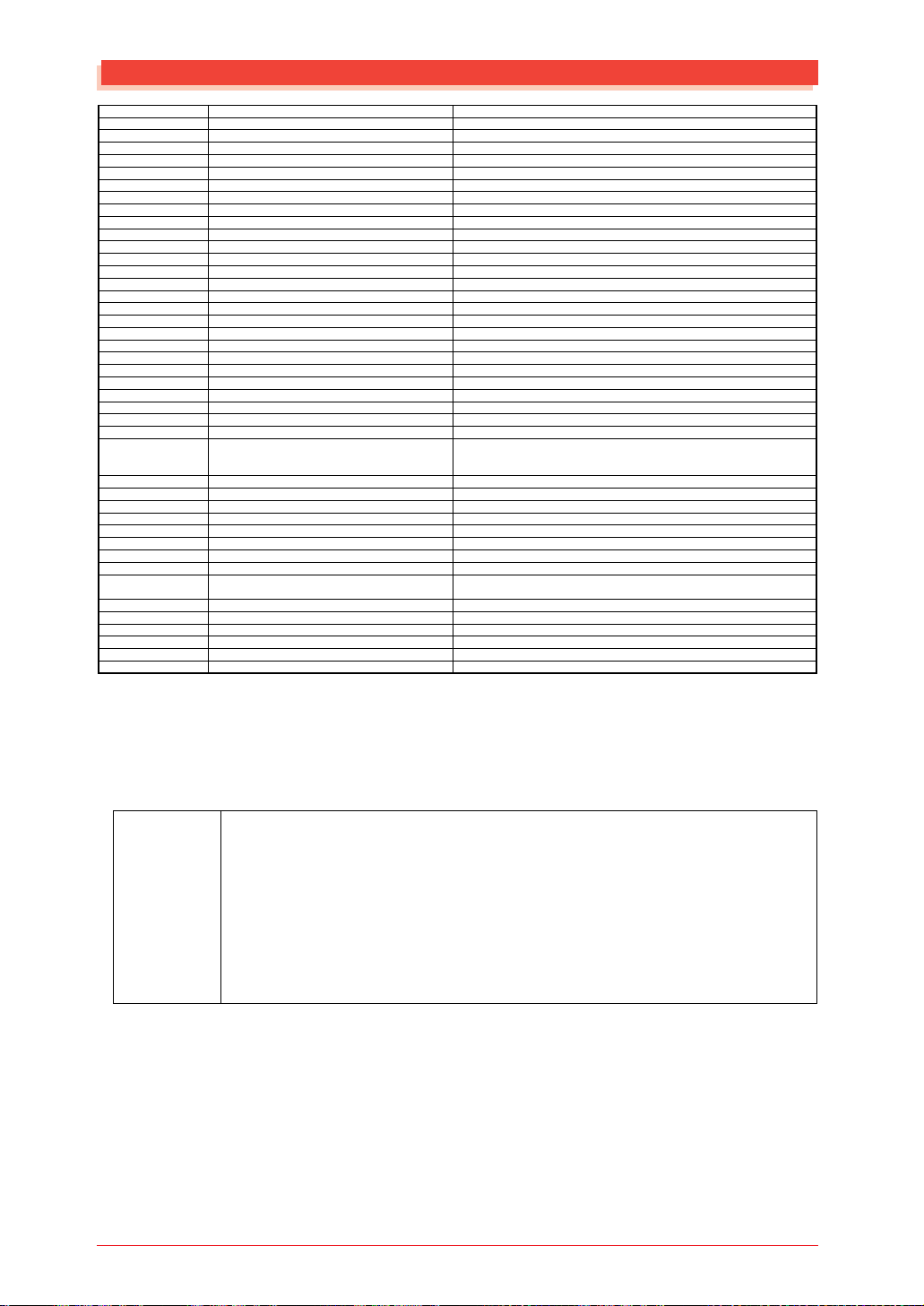
Variation, Insertion Block: when input mode
= "mono"
L
R
LSF HSF
LSF HSF
+
CHORUS
dry (L)
dry (R)
Variation, Insertion Block: when input mode
= "stereo"
L
R
LSF HSF
CHORUS
CHORUS
LSF HSF
dry (L)
dry (R)
L
R
L
R
13
Page 13
Effect Parameter List
● FLANGER 1, 2, 3
(Chorus, Variation, Insertion 1, 2 block)
No.
Parameter
1
LFO Frequency
2
LFO Depth
3
Feedback Level
4
Delay Offset
5
6
EQ Low Frequency
7
EQ Low Gain
8
EQ High Frequency
9
EQ High Gain
10
Dry/Wet
11
EQ Mid Frequency
12
EQ Mid Gain
13
EQ Mid Width
14
LFO Phase Difference
15
16
Display
0.00Hz – 39.7Hz
0 – 127
-63 – +63
0 – 63
32Hz – 2.0kHz
-12 – +12dB
500Hz – 16.0kHz
-12 – +12dB
D63>W – D=W – D<W63
100Hz – 10.0kHz (variation block)
-12 – +12dB (variation block)
1.0 – 12.0 (variation block)
-180 – +180deg
0-127
0-127
1-127
0-63
4-40
52-76
28-58
52-76
1-127
14-54
52-76
10-120
4-124
Chorus Block
L
LSF HSF
FLANGER
FLANGER
R
LSF HSF
Variation, Insertion Block
L
LSF HSF
FLANGER
FLANGER
R
LSF HSF
See Table
table#1
table#2
table#3
table#3
table#3
resolution=3deg.
dry (L)
dry (R)
Variation, Insertion Block
L
R
LSF HSF
LSF HSF
+
SYMPHONIC
ControlValue
dry (L)
dry (R)
L
R
● ENSEMBLE DETUNE
(Chorus, Variation, Insertion 1, 2 block)
No.
Parameter
1
L
R
L
Detune
2
Lch Init Delay
3
Rch Init Delay
4
5
6
7
8
9
10
Dry/Wet
11
EQ Low Frequency
12
EQ Low Gain
13
EQ High Frequency
14
EQ High Gain
15
16
Chorus Block
L
R
R
Display
-50 – +50cent
0 – 127
0 – 127
D63>W – D=W – D<W63
32Hz – 2.0kHz (variation, insertion1,2 block)
-12 – +12dB (variation, insertion1,2 block)
500Hz – 16.0kHz (variation, insertion1,2 block)
-12 – +12dB (variation, insertion1,2 block)
PITCH CHANGE
PITCH CHANGE
14-114
0-127
0-127
1-127
52-76
28-58
52-76
L
R
4-40
See Table
table#2
table#2
table#3
table#3
ControlValue
● SYMPHONIC
(Chorus, Variation, Insertion 1, 2 block)
No.
Parameter
1
LFO Frequency
2
LFO Depth
3
Delay Offset
4
5
6
EQ Low Frequency
7
EQ Low Gain
8
EQ High Frequency
9
EQ High Gain
10
Dry/Wet
11
EQ Mid Frequency
12
EQ Mid Gain
13
EQ Mid Width
14
15
16
Display
0.00Hz – 39.7Hz
0 – 127
0 – 127
32Hz – 2.0kHz
-12 – +12dB
500Hz – 16.0kHz
-12 – +12dB
D63>W – D=W – D<W63
100Hz – 10.0kHz (variation block)
-12 – +12dB (variation block)
1.0 – 12.0 (variation block)
0-127
0-127
0-127
4-40
52-76
28-58
52-76
1-127
14-54
52-76
10-120
Chorus Block
L
LSF HSF
+
SYMPHONIC
R
LSF HSF
14
ControlValue
See Table
table#1
table#2
table#3
table#3
table#3
MU128 EFFECT
Variation, Insertion Block
L
LSF HSF
R
LSF HSF
● AMBIENCE (Variation block)
No.
Parameter
1
Delay Time
2
Output Phase
L
R
3
4
5
6
EQ Low Frequency
7
EQ Low Gain
8
EQ High Frequency
9
EQ High Gain
10
Dry/Wet
11
12
13
14
15
16
Display
0 – 127
normal/invers
32Hz – 2.0kHz
-12 – +12dB
500Hz – 16.0kHz
-12 – +12dB
D63>W – D=W – D<W63
PITCH CHANGE
PITCH CHANGE
0-127
0-1
4-40
52-76
28-58
52-76
1-127
dry (L)
dry (R)
See Table
table#2
table#3
table#3
L
R
ControlValue
Page 14
Effect Parameter List
L
LSF HSF
+
AMBIENCE
R
LSF HSF
● ROTARY SPEAKER
(Variation, Insertion 1, 2 block)
No.
1
2
3
4
5
6
7
8
9
10
11
12
13
14
15
16
L
R
Parameter
LFO Frequency
LFO Depth
EQ Low Frequency
EQ Low Gain
EQ High Frequency
EQ High Gain
Dry/Wet
EQ Mid Frequency
EQ Mid Gain
EQ Mid Width
LSF HSF
LSF HSF
Display
0.00Hz – 39.7Hz
0 – 127
32Hz – 2.0kHz
-12 – +12dB
500Hz – 16.0kHz
-12 – +12dB
D63>W – D=W – D<W63
100Hz – 10.0kHz (variation block)
-12 – +12dB (variation block)
1.0 – 12.0 (variation block)
+
ROTARY SP.
0-127
0-127
4-40
52-76
28-58
52-76
1-127
14-54
52-76
10-120
dry (L)
dry (R)
dry (L)
dry (R)
See Table
table#1
table#3
table#3
table#3
● TREMOLO (Variation, Insertion 1, 2 block)
L
No.
Parameter
1
LFO Frequency
2
AM Depth
3
PM Depth
4
5
6
EQ Low Frequency
7
EQ Low Gain
8
EQ High Frequency
9
R
EQ High Gain
10
11
EQ Mid Frequency
12
EQ Mid Gain
13
EQ Mid Width
14
LFO Phase Difference
15
Input Mode
16
Display
0.00Hz – 39.7Hz
0 – 127
0 – 127
32Hz – 2.0kHz
-12 – +12dB
500Hz – 16.0kHz
-12 – +12dB
100Hz – 10.0kHz (variation block)
-12 – +12dB (variation block)
1.0 – 12.0 (variation block)
-180 – +180deg
mono/stereo
0-127
0-127
0-127
4-40
52-76
28-58
52-76
14-54
52-76
10-120
4-124
0-1
See Table
table#1
table#3
table#3
table#3
resolution=3deg.
ControlValue
When input mode="mono"
ControlValue
L
R
LSF HSF
LSF HSF
+
TREMOLO
L
R
When input mode="stereo"
L
L
LSF HSF
TOREMOLO
TOREMOLO
R
R
LSF HSF
L
R
● 2WAY ROTARY SPEAKER
(Variation block)
No.
Parameter
1
Rotor Speed
2
Drive Low
3
Drive High
4
Low/High
5
6
EQ Low Frequency
7
EQ Low Gain
8
EQ High Frequency
9
EQ High Gain
10
11
Crossover Frequency
12
Mic L-R Angle
13
14
15
16
L
R
+
High
Low
Display
0.0Hz – 39.7Hz
0 – 127
0 – 127
L63>H – L=H – L<H63
32Hz – 2.0kHz
-12 – +12dB
500Hz – 16.0kHz
-12 – +12dB
100Hz – 10.0kHz
0deg – 180deg
HSF
LSF
HORN
ROTOR
0-127
0-127
0-127
1-127
4-40
52-76
28-58
52-76
14-54
0-60
See Table
table#1
table#3
table#3
table#3
resolution=3deg.
+
+
● AUTO PAN (Variation, Insertion 1, 2 block)
No.
Parameter
1
ControlValue
L
R
2
3
4
5
6
7
8
9
10
11
12
13
14
15
16
L
R
LFO Frequency
L/R Depth
F/R Depth
PAN Direction
EQ Low Frequency
EQ Low Gain
EQ High Frequency
EQ High Gain
EQ Mid Frequency
EQ Mid Gain
EQ Mid Width
LSF HSF
LSF HSF
Display
0.00Hz – 39.7Hz
0 – 127
0 – 127
L<->R,L->R,L<-R,Lturn,Rturn,L/R
32Hz – 2.0kHz
-12 – +12dB
500Hz – 16.0kHz
-12 – +12dB
100Hz – 10.0kHz (variation block)
-12 – +12dB (variation block)
1.0 – 12.0 (variation block)
+
AUTO PAN
0-127
0-127
0-127
0-5
4-40
52-76
28-58
52-76
14-54
52-76
10-120
See Table
table#1
table#3
table#3
table#3
ControlValue
L
R
MU128 EFFECT
15
Page 15
Effect Parameter List
● PHASER 1
(Chorus, Variation, Insertion 1, 2 block)
No.
Parameter
1
LFO Frequency
2
LFO Depth
3
Phase Shift Offset
4
Feedback Level
5
6
EQ Low Frequency
7
EQ Low Gain
8
EQ High Frequency
9
EQ High Gain
10
Dry/Wet
11
Stage
12
Diffusion
13
14
15
16
Display
0.00Hz – 39.7Hz
0 – 127
0 – 127
-63 – +63
32Hz – 2.0kHz
-12 – +12dB
500Hz – 16.0kHz
-12 – +12dB
D63>W – D=W – D<W63
4,5,6 (chorus, insertion1,2 block)
4 – 12 (variation block)
mono/stereo
0-127
0-127
0-127
1-127
4-40
52-76
28-58
52-76
1-127
4-12
4-6
0-1
Chorus Block
L
LSF HSF
+
PHASER
R
LSF HSF
Variation, Insertion Block
L
LSF HSF
+
PHASER
See Table
table#1
table#3
table#3
dry (L)
● DISTORTION
OVERDRIVE (Variation, Insertion 1, 2 block)
No.
ControlValue
Parameter
1
Drive
2
EQ Low Frequency
3
EQ Low Gain
4
LPF Cutoff
5
Output Level
6
7
EQ Mid Frequency
8
EQ Mid Gain
9
EQ Mid Width
10
Dry/Wet
11
Edge(Clip Curve)
12
13
14
15
16
Display
0 – 127
32Hz – 2.0kHz
-12 – +12dB
1.0k – Thru
0 – 127
100Hz – 10.0kHz
-12 – +12dB
1.0 – 12.0
D63>W – D=W – D<W63
0 – 127
0-127
4-40
52-76
34-60
0-127
14-54
52-76
10-120
1-127
0-127
See Table
table#3
table#3
table#3
mild to sharp
ControlValue
AMP SIMULATOR
(Variation, Insertion 1, 2 block)
No.
L
R
L
Parameter
1
Drive
2
AMP Type
3
LPF Cutoff
4
Output Level
5
6
7
8
9
10
Dry/Wet
11
Edge(Clip Curve)
12
13
14
15
16
Variation Block
Display
0 – 127
Off,Stack,Combo,Tube
1.0k – Thru
0 – 127
D63>W – D=W – D<W63
0 – 127
L
0-127
0-3
34-60
0-127
1-127
0-127
See Table
table#3
mild to sharp
dry (L)
ControlValue
L
R
LSF HSF
● PHASER 2 (Variation block)
No.
Parameter
1
LFO Frequency
2
LFO Depth
3
Phase Shift Offset
4
Feedback Level
5
6
EQ Low Frequency
7
EQ Low Gain
8
EQ High Frequency
9
EQ High Gain
10
Dry/Wet
11
Stage
12
13
LFO Phase Difference
14
15
16
L
R
LSF HSF
LSF HSF
Display
0.00Hz – 39.7Hz
0 – 127
0 – 127
-63 – +63
32Hz – 2.0kHz
-12 – +12dB
500Hz – 16.0kHz
-12 – +12dB
D63>W – D=W – D<W63
3,4,5,6
-180deg – +180deg
PHASER
PHASER
0-127
0-127
0-127
1-127
4-40
52-76
28-58
52-76
1-127
4-124
3-6
dry (R)
See Table
table#1
table#3
table#3
resolution=3deg.
dry (L)
dry (R)
R
+
GATE
DISTORTION
EF
R
ControlValue
Insertion Block
L
+
R
dry (L)
DISTORTION
dry (R)
dry (R)
L
R
R
L
R
16
MU128 EFFECT
Page 16
Effect Parameter List
● COMP+DIST (Variation block)
No.
1
2
3
4
5
6
7
8
9
10
11
12
13
14
15
16
L
R
Parameter
Drive
EQ Low Frequency
EQ Low Gain
LPF Cutoff
Output Level
EQ Mid Frequency
EQ Mid Gain
EQ Mid Width
Dry/Wet
Edge(Clip Curve)
Attack
Release
Threshold
Ratio
+
Display
0 – 127
32Hz – 2.0kHz
-12 – +12dB
1.0k – Thru
0 – 127
100Hz – 10.0kHz
-12 – +12dB
1.0 – 12.0
D63>W – D=W – D<W63
0 – 127
1ms – 40ms
10ms – 680ms
-48dB – -6dB
1.0 – 20.0
COMP
EF
DISTORTION
● 3BAND EQ (MONO)
(Variation, Insertion 1, 2 block)
No.
Parameter
1
EQ Low Gain
2
EQ Mid Frequency
3
EQ Mid Gain
4
EQ Mid Width
5
EQ High Gain
6
EQ Low Frequency
7
EQ High Frequency
8
9
10
11
12
13
14
15
Input Mode
16
Display
-12 – +12dB
100Hz – 10.0kHz
-12 – +12dB
1.0 – 12.0
-12 – +12dB
50Hz – 2.0kHz
500Hz – 16.0kHz
mono/stereo
When input mode="mono"
L
+
LSF PDF HSF
R
When input mode="stereo"
0-127
4-40
52-76
34-60
0-127
14-54
52-76
10-120
1-127
0-127
0-19
0-15
79-121
52-76
14-54
52-76
10-120
52-76
8-40
28-58
L
R
0-7
0-1
See Table
table#3
table#3
table#3
mild to sharp
table#8
table#9
table#10
dry (L)
dry (R)
See Table
table#3
table#3
table#3
● 2BAND EQ (STEREO)
ControlValue
L
R
ControlValue
(Variation, Insertion 1, 2 block)
No.
1
2
3
4
5
6
7
8
9
10
11
12
13
14
15
16
L
R
Parameter
EQ Low Frequency
EQ Low Gain
EQ High Frequency
EQ High Gain
LSF HSF
LSF HSF
Display
32Hz – 2.0kHz
-12 – +12dB
500Hz – 16.0kHz
-12 – +12dB
L
R
4-40
52-76
28-58
52-76
See Table
table#3
table#3
ControlValue
● AUTO WAH (Variation, Insertion 1, 2 block)
No.
Parameter
1
LFO Frequency
2
LFO Depth
3
Cutoff Frequency Offset
4
Resonance
5
6
EQ Low Frequency
7
EQ Low Gain
8
EQ High Frequency
9
EQ High Gain
10
Dry/Wet
11
Drive (Variation block)
12
13
14
15
16
Display
0.00Hz – 39.7Hz
0 – 127
0 – 127
1.0 – 12.0
32Hz – 2.0kHz
-12 – +12dB
500Hz – 16.0kHz
-12 – +12dB
D63>W – D=W – D<W63
0 – 127
0-127
0-127
0-127
10-120
4-40
52-76
28-58
52-76
1-127
0-127
See Table
table#1
table#3
table#3
ControlValue
Variation Block
L
R
LSF HSF
LSF HSF
AUTO WAH
AUTO WAH
dry (L)
dry (R)
+
DISTORTION
dry (L)
dry (R)
L
R
Insertion Block
L
LSF HSF
dry (L)
L
L
R
LSF PDF
LSF PDF
HSF
HSF
L
R
R
MU128 EFFECT
LSF HSF
AUTO WAH
AUTO WAH
dry (R)
R
17
Page 17
Effect Parameter List
● AUTO WAH+DIST
AUTO WAH+ODRV (Variation block)
No.
Parameter
1
LFO Frequency
2
LFO Depth
3
Cutoff Frequency Offset
4
Resonance
5
6
EQ Low Frequency
7
EQ Low Gain
8
EQ High Frequency
9
EQ High Gain
10
Dry/Wet
11
Drive
12
EQ Low Gain(distortion)
13
EQ Mid Gain(distortion)
14
LPF Cutoff
15
Output Level
16
L
LSF HSF
R
LSF HSF
Display
0.00Hz – 39.7Hz
0 – 127
0 – 127
1.0 – 12.0
32Hz – 2.0kHz
-12 – +12dB
500Hz – 16.0kHz
-12 – +12dB
D63>W – D=W – D<W63
0 – 127
-12 – +12dB
-12 – +12dB
1.0kHz – thru
0 – 127
dry (L)
AUTO WAH
AUTO WAH
dry (R)
0-127
0-127
0-127
10-120
52-76
28-58
52-76
1-127
0-127
52-76
52-76
34-60
0-127
+
DISTORTION
4-40
See Table
table#1
table#3
table#3
table#3
dry (L)
dry (R)
● TOUCH WAH 1
(Variation, Insertion 1, 2 block)
ControlValue
L
TOUCH WAH+DIST (Variation block)
No.
Parameter
1
Sensitive
2
Cutoff Frequency Offset
3
Resonance
4
5
6
EQ Low Frequency
7
EQ Low Gain
8
EQ High Frequency
9
EQ High Gain
10
Dry/Wet
11
Drive (Variation block)
12
13
14
15
16
Display
0 – 127
0 – 127
1.0 – 12.0
32Hz – 2.0kHz
-12 – +12dB
500Hz – 16.0kHz
-12 – +12dB
D63>W – D=W – D<W63
0 – 127
0-127
0-127
10-120
4-40
52-76
28-58
52-76
1-127
0-127
See Table
table#3
table#3
ControlValue
Variation Block: TOUCH WAH 1
dry (L)
dry (R)
L
R
TOUCH WAH
TOUCH WAH
dry (L)
dry (R)
+
DISTORTION
L
LSF HSF
R
R
LSF HSF
+
EF
Insertion Block: TOUCH WAH 1
L
LSF HSF
EF
TOUCH WAH
TOUCH WAH
+
dry (L)
L
R
LSF HSF
Variation Block: TOUCH WAH+DIST
TOUCH WAH
TOUCH WAH
dry (L)
dry (R)
+
DISTORTION
L
R
LSF HSF
LSF HSF
+
EF
dry (R)
dry (L)
dry (R)
R
L
R
18
MU128 EFFECT
Page 18
R
R
Effect Parameter List
● TOUCH WAH 2
(Variation, Insertion 1, 2 block)
TOUCH WAH+ODRV (Variation block)
No.
Parameter
1
Sensitive
2
Cutoff Frequency Offset
3
Resonance
4
5
6
EQ Low Frequency
7
EQ Low Gain
8
EQ High Frequency
9
EQ High Gain
10
Dry/Wet
11
Drive
12
EQ Low Gain(distortion)
13
EQ Mid Gain(distortion)
14
LPF Cutoff
15
Output Level
16
Release
Display
0 – 127
0 – 127
1.0 – 12.0
32Hz – 2.0kHz
-12 – +12dB
500Hz – 16.0kHz
-12 – +12dB
D63>W – D=W – D<W63
0 – 127
-12 – +12dB
-12 – +12dB
1.0kHz – thru
0 – 127
10 – 680ms
0-127
0-127
10-120
4-40
52-76
28-58
52-76
1-127
0-127
52-76
52-76
34-60
0-127
52-67
Variation Block: TOUCH WAH 2
L
R
LSF HSF
LSF HSF
TOUCH WAH
+
EF
TOUCH WAH
dry (L)
dry (R)
+
DISTORTION
Insertion Block: TOUCH WAH 2
L
LSF HSF
EF
TOUCH WAH
TOUCH WAH
+
See Table
table#3
table#3
table#3
dry (L)
dry (L)
dry (R)
● PITCH CHANGE 1 (Variation block)
No.
Parameter
1
Pitch
2
Initial Delay
3
Fine 1
4
Fine 2
5
ControlValue
Feedback Level
6
7
8
9
10
Dry/Wet
11
Pan 1
12
Output Level 1
13
Pan 2
14
Output Level 2
15
16
Display
-24 – +24
0 – 127
-50 – +50
-50 – +50
-99 – +99%
D63>W – D=W – D<W63
L63 – R63
0 – 127
L63 – R63
0 – 127
40-88
0-127
14-114
14-114
1-127
1-127
1-127
0-127
1-127
0-127
See Table
table#7
ControlValue
PITCH CHANGE 2 (Variation block)
No.
Parameter
1
Pitch
2
Initial Delay
3
Fine 1
4
Fine 2
5
Feedback Level
6
L
7
8
9
10
Dry/Wet
11
Pan 1
12
Output Level 1
13
Pan 2
14
Output Level 2
15
16
L
L
Display
-24 – +24
0 – 127
-50 – +50cent
-50 – +50cent
-99 – +99%
D63>W – D=W – D<W63
L63 – R63
0 – 127
L63 – R63
0 – 127
PITCH CHANGE
+
dry (L)
PITCH CHANGE
40-88
0-127
14-114
14-114
1-127
1-127
1-127
0-127
1-127
0-127
L
See Table
table#7
ControlValue
R
LSF HSF
Variation Block: TOUCH WAH+ODRV
L
R
LSF HSF
LSF HSF
TOUCH WAH
+
EF
TOUCH WAH
dry (L)
dry (R)
+
DISTORTION
dry (R)
dry (L)
dry (R)
R
R
dry (R)
R
L
MU128 EFFECT
19
Page 19
Effect Parameter List
● HARMONIC ENHANCER*
● COMPRESSOR
(Variation, Insertion 1, 2 block)
No.
1
2
3
4
5
6
7
8
9
10
11
12
13
14
15
16
Parameter
HPF Cutoff
Drive
Mix Level
Display
500Hz – 16.0kHz
0 – 127
0 – 127
28-58
0-127
0-127
See Table
table#3
ControlValue
* The Harmonic Enhancer produces the same effect as its MU series predecessor.
No.
10
11
12
13
14
15
16
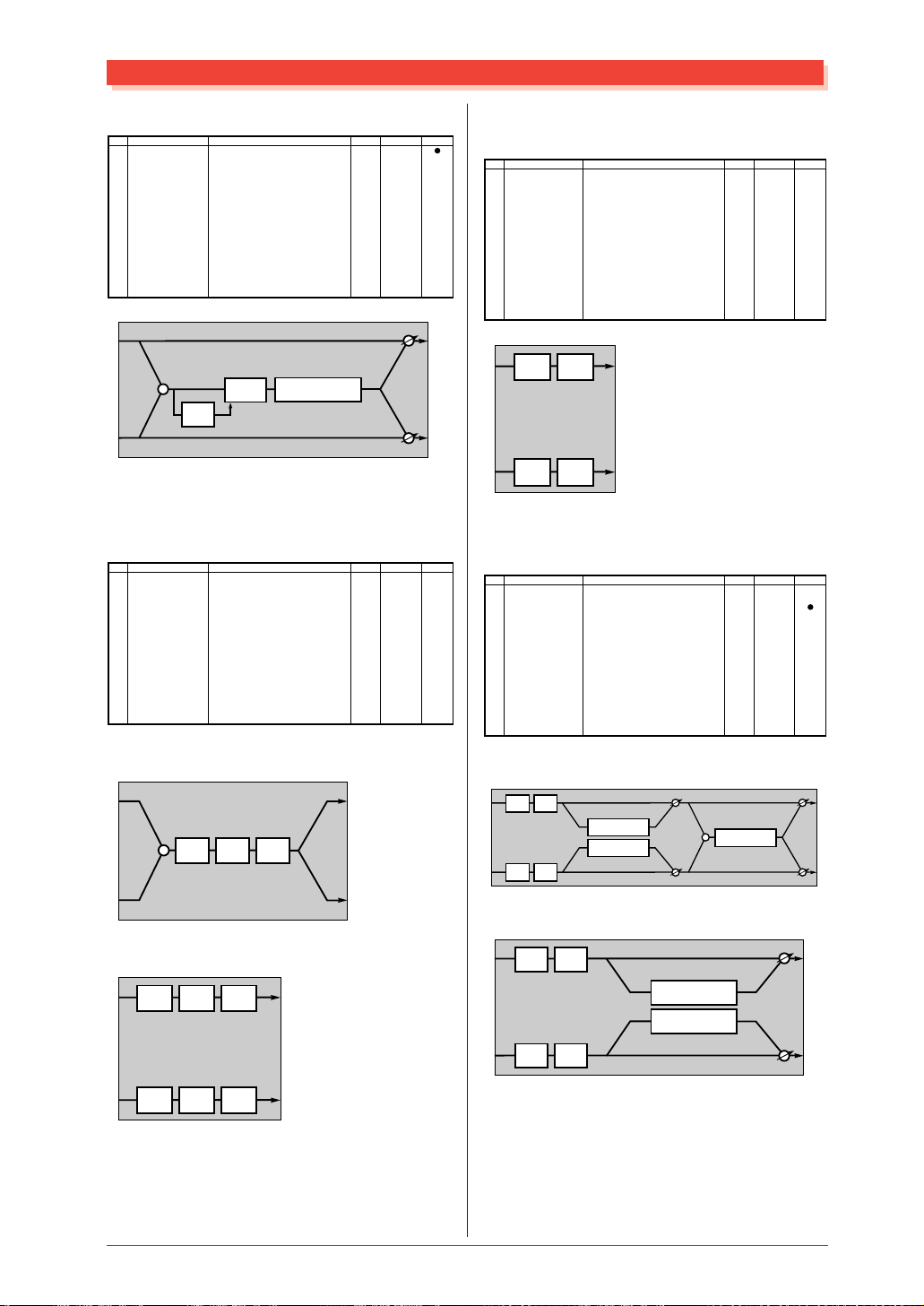
Variation Block
L
+
ENHANCER
EF
+
L
ENHANCER
R
+
R
L
R
Insertion Block
L
+
ENHANCER
+
L
EF
R
+
R
L
R
(Variation, Insertion 1, 2 block)
Parameter
1
Attack
2
Release
3
Threshold
4
Ratio
5
Output Level
6
7
8
9
Display
1 – 40ms
10 – 680ms
-48 – -6dB
1.0 – 20.0
0 – 127
Variation Block
+
COMP
EF
COMP
Insertion Block
+
COMP
EF
0-19
0-15
79-121
0-7
0-127
L
R
L
R
See Table
table#8
table#9
table#10
ControlValue
20
MU128 EFFECT
Page 20
Effect Parameter List
● NOISE GATE (Variation, Insertion 1, 2 block)
No.
1
2
3
4
5
6
7
8
9
10
11
12
13
14
15
16
Parameter
Attack
Release
Threshold
Output Level
Display
1 – 40ms
10 – 680ms
-72 – -30dB
0 – 127
0-19
0-15
55-97
0-127
See Table
table#8
table#9
ControlValue
Variation Block
L
+
GATE
EF
GATE
R
L
R
Insertion Block
L
+
GATE
EF
R
L
R
● VOICE CANCEL (Variation block)
No.
Parameter
1
2
3
4
5
6
7
8
9
10
11
Low Adjust
12
High Adjust
13
14
15
16
L
Display
0 – 26
0 – 26
ControlValue
See Table
0-26
0-26
+
L
VOICE CANCEL
VOICE CANCEL
R
+
R
● TALKING MODULATOR (Variation block)
No.
1
2
3
4
5
6
7
8
9
10
11
12
13
14
15
16
Parameter
Vowel
Move speed
Drive
Output level
Display
a,i,u,e,o
1 – 62
0 – 127
0 – 127
0-4
1-62
0-127
0-127
See Table
ControlValue
L
R
MU128 EFFECT
L
+
ENHANCER
+
TALK MOD.
EF
R
21
Page 21
L
R
Effect Parameter List
● LO-FI (Variation block)
No.
Parameter
1
sampling freq control
2
word length
3
output gain
4
LPF Cutoff
5
filter type
6
LPF resonance
7
bit assign
8
emphasis
9
10
Dry/Wet
11
12
13
14
15
Input Mode
16
Display
44.1kHz – 345Hz
1 – 127
-6 – +12dB
63Hz – thru
Thru,PowerBass,Radio,Telephone,Clean,Low
1.0 – 12.0
0 – 6
off/on
D63>W – D=W – D<W63
mono/stereo
When input mode="mono"
L
+
Lo-Fi
R
When input mode="stereo"
L
Lo-Fi
Lo-Fi
R
dry (L)
dry (R)
dry (L)
dry (R)
0-127
1-127
10-60
10-120
1-127
L
R
L
R
0-18
● COMP+DIST+DELAY (Variation block)
See Table
ControlValue
0-5
0-6
0-1
0-1
COMP+ODRV+DELAY (Variation block)
No.
Parameter
1
Delay Time
2
Delay Feedback Level
3
Delay Mix
4
Dist Drive
5
Dist Output Level
6
Dist EQ Low Gain
7
Dist EQ Mid Gain
8
9
10
Dry/Wet
11
Comp. Attack
12
Comp. Release
13
Comp. Threshold
14
Comp. Ratio
15
16
L
+ +
R
EF
Display
0.1 – 1486.0ms
-63 – +63
0 – 127
0 – 127
0 – 127
-12 – +12dB
-12 – +12dB
D63>W – D=W – D<W63
1ms – 40ms
10ms – 680ms
-48dB – -6dB
1.0 – 20.0
dry (L)
COMP
DISTORTION DELAY
dry (R)
1-14860
1-127
0-127
0-127
0-127
52-76
52-76
1-127
0-19
0-15
79-121
0-7
See Table
table#8
table#9
table#10
LPF
ControlValue
+
L
+
R
● WAH+DIST+DELAY (Variation block)
WAH+ODRV+DELAY (Variation block)
No.
Parameter
1
Delay Time
2
Delay Feedback Level
3
Delay Mix
4
Dist Drive
5
Dist Output Level
6
Dist EQ Low Gain
7
Dist EQ Mid Gain
8
9
10
Dry/Wet
11
Wah Sensitive
12
Wah Cutoff Freq Offset
13
Wah Resonance
14
Wah Release
15
16
Display
0.1 – 1486.0ms
-63 – +63
0 – 127
0 – 127
0 – 127
-12 – +12dB
-12 – +12dB
D63>W – D=W – D<W63
0 – 127
0 – 127
1.0 – 12.0
10 – 680ms
1-14860
1-127
0-127
0-127
0-127
52-76
52-76
1-127
0-127
0-127
10-120
52-67
See Table
ControlValue
● DIST+DELAY (Variation block)
OVERDRIVE+DELAY (Variation block)
No.
Parameter
1
Lch Delay Time
2
Rch Delay Time
3
Delay Feedback Time
4
Delay Feedback Level
5
Delay Mix
6
Dist Drive
7
Dist Output Level
8
Dist EQ Low Gain
9
Dist EQ Mid Gain
10
Dry/Wet
11
12
13
14
15
16
L
+ +
R
EF
Display
0.1 – 1486.0ms
0.1 – 1486.0ms
0.1 – 1486.0ms
-63 – +63
0 – 127
0 – 127
0 – 127
-12 – +12dB
-12 – +12dB
D63>W – D=W – D<W63
dry (L)
GATE
DISTORTION DELAY
dry (R)
1-14860
1-14860
1-14860
1-127
0-127
0-127
0-127
52-76
52-76
1-127
See Table
LPF
TOUCH WAH
dry (L)
+
dry (R)
L
+ +
ControlValue
EF
R
dry (L)
DISTORTION DELAY
LPF
dry (R)
+
L
+
R
+
L
R
+
22
MU128 EFFECT
Page 22
Explanation of effect parameters
Effect Parameter List
Parameter name
AM Depth
AMP Type
Attack
Bit Assign
Cch Delay
Cch Level
Crossover Frequency
Cutoff Frequency Offset
Delay Mix
Delay Offset
Delay Time
Delay2 Level
Density
Depth
Detune
Diffusion
Drive
Drive High
Drive Low
Dry/Wet
Edge(Clip Curve)
Emphasis
EQ High Frequency
EQ High Gain
EQ Low Frequency
EQ Low Gain
EQ Mid Frequency
EQ Mid Gain
EQ Mid Width
Er/Rev Balance
F/R Depth
Feedback Delay
Feedback Delay 1
Feedback Delay 2
Feedback Level
Filter Type
Fine 1
Fine 2
Height
High Adjust
High Damp
HPF Cutoff
Initial Delay
Input Mode
Input Select
L/R Depth
L->R Delay
Lch Delay
Lch Delay1
Lch Delay2
Lch Feedback Level
Lch Init Delay
LFO Depth
LFO Frequency
Effect types in which the parameter exists
TREMOLO
AMP SIMULATOR
COMPRESSOR type
NOISE GATE
LO-FI
DELAY L,C,R
DELAY L,C,R
2WAY ROTARY SPEAKER
WAH type
DIST+DELAY,OVERDRIVE+DELAY,
COMP+DIST+DELAY,COMP+ODRV+DELAY,
WAH+DIST+DELAY,WAH+ODRV+DELAY
CHORUS type
KARAOKE1,2,3
AMBIENCE
ECHO
REVERB type, EARLY REF type
REVERB type
ENSEMBLE DETUNE
REVERB type, EARLY REF type, PHASER
DISTORTION type
HARMONIC ENHANCER*
TALKING MODULATION
2WAY ROTARY SPEAKER
2WAY ROTARY SPEAKER
All types
DISTORTION type
LO-FI
All types
All types
All types
All types
All types
All types
All types
REVERB type
AUTO PAN
DELAY L,C,R
DELAY L,R
DELAY L,R
REVERB type
DELAY type,EARLY REF type,PITCH CHANGE type
KARAOKE type
CHORUS type, FLANGER type
PHASER type
LO-FI
PITCH CHANGE type
PITCH CHANGE type
REVERB type
VOICE CANCELAR
REVERB type,DELAY type,EARLY REF type
REVERB type,EARLY REF type,KARAOKE type,HARMONIC ENHANCER*
REVERB type
EARLY REF type
PITCH CHANGE type
All types
CROSS DELAY
AUTO PAN
CROSS DELAY
DELAY type
ECHO
ECHO
ECHO
ENSEMBLE DETUNE
CHORUS type,FLANGER type,SYMPHONIC
ROTARY SPEAKER
PHASER type
WAH type
CHORUS type,FLANGER type,SYMPHONIC
ROTARY SPEAKER
TREMOLO
AUTO PAN
PHASER type
WAH type
Explanation of parameter
Depth of volume modulation
Select the type of amp to be simulated
Time until the compressor effect begins to apply
Time until the gate begins to open
Adjust the word length of the audio data
Length of the center channel delay
Volume of the center channel
Crossover frequency between the high-range and low-range speakers
Frequency offset value that will control the wah filter
Mixing amount of delay sound
Offset value of delay modulation
Spacing of reflections for karaoke echo
Delay length
Volume of second delay
Density of reflections. Higher values produce closer spacing
Depth of the simulated room
Amount of pitch shift
Control the spaciousness
Depth of distortion
Depth at which the exciter effect is applied
Depth at which the exciter effect is applied
Depth of modulation caused by rotation of the low-range speaker
Depth of modulation caused by rotation of the high-range speaker
Balance between dry sound and effect sound
Curve of distortion characteristics (sharp(127) distorts suddenly, mild(0) distorts gradually)
Modify the character of the high range
Frequency at which the EQ will boost/cut the high range
Gain amount by which the EQ will boost/cut the high range
Frequency at which the EQ will boost/cut the low range
Gain amount by which the EQ will boost/cut the low range
Frequency at which the EQ will boost/cut the mid range
Gain amount by which the EQ will boost/cut the mid range
Width of the area boosted/cut by the mid-range EQ
Level balance between the early reflections and the reverberation
Depth of front/back panning (valid when PAN Direction=Lturn,Rturn)
Length of feedback delay
Length of feedback delay 1
Length of feedback delay 2
Feedback amount of initial delay
Feedback amount
Setting for repeated reflections
Level at which delay output is again returned to the input (negative values invert the phase)
Level at which phaser output is again returned to the input (negative values insert the phase)
Select the type of tonal effect
Fine adjustment to pitch of first sound
Fine adjustment to pitch of second sound
Height of simulated room
Adjust the upper limit of the mid-frequency range that will be attenuated
Attenuation of the high frequency range (lower values will cause the high range to decay more rapidly)
Frequency at which the high pass filter will cut the low range
Delay time until the early reflections
Delay length until ER (GateReverb) sounds
Delay length
Mono/stereo switch for input
Input select
Depth of left/right panning
Delay time from left (input) to right (output)
Length of left channel delay
Length of first left channel delay
Length of second left channel delay
Amount of left channel feedback
Length of left channel delay
Depth of delay modulation
Depth of modulation caused by speaker rotation
Depth of phase modulation
Depth at which the wah filter will be controlled
Frequency of delay modulation
Frequency at which the speaker will rotate
Modulation frequency
Autopan frequency
Phase modulation frequency
Frequency at which wah filter will be controlled
* The Harmonic Enhancer produces the same effect as its MU series predecessor.
MU128 EFFECT
23
Page 23
Effect Parameter List
LFO Phase Difference
Liveness
Low Adjust
Low/High
LPF Cutoff
LPF Resonance
Mic L-R Angle
Mix Level
Move Speed
Output Gain
Output Level
Output Level 1
Output Level 2
Output Phase
Pan 1
Pan 2
PAN Direction
Phase Shift Offset
Pitch
PM Depth
R->L Delay
Ratio
Rch Delay
Rch Delay1
Rch Delay2
Rch Feedback Level
Rch Init Delay
Release
Resonance
Rev Delay
Reverb Time
Room Size
Rotor Speed
Sampling Freq Control
Sensitive
Stage
Threshold
Type
Vowel
Wah Release
Wall Vary
Width
Word Length
PHASER type,FLANGER type
EARLY REF type
VOICE CANCEL
2WAY ROTARY SPEAKER
All types
LO-FI
2WAY ROTARY SPEAKER
HARMONIC ENHANCER*
TALKING MODULATOR
LO-FI
All types
PITCH CHANGE type
PITCH CHANGE type
AMBIENCE
PITCH CHANGE type
PITCH CHANGE type
AUTO PAN
PHASER type
PITCH CHANGE type
TREMOLO
CROSS DELAY
COMPRESSOR type
DELAY type
ECHO
ECHO
ECHO
ENSEMBLE DETUNE
COMPRESSOR type
NOISE GATE
TOUCH WAH2, TOUCH WAH+ODRV
WAH type
REVERB type
REVERB type
EARLY REF type
2WAY ROTARY SPEAKER
LO-FI
WAH type
PHASER type
COMPRESSOR type
NOISE GATE
EARLY REF type
TALKING MODULATOR
WAH+DIST+DELAY,WAH+ODRV+DELAY
REVERB type
REVERB type
LO-FI
L/R phase difference for modulation waveform (0 deg (=64) is no phase difference)
ER decay. Lower values cause faster decay.
Adjust the lower frequency limit of the mid-range that will be attenuated
Volume balance between the high-range and low-range speakers
Frequency at which the low pass filter will cut the high frequency range
Add character to the low pass filter of the input
L/R angle of the mic that picks up the output
Level of the effect sound that is mixed into the dry sound
Time over which the sound specified by Vowel is reached
Output gain
Output level
Output level for first unit
Output level for second unit
Swap phase of the effect sound between L/R
Pan of first unit
Pan of second unit
Autopan type (L<->R is sine wave, L/R is square wave)
Offset value for phase modulation
Pitch setting in semitones
Depth of delay modulation
Delay time from right (input) to left (output)
Compression ratio of the compressor
Length of right channel delay
Length of first right channel delay
Length of second right channel delay
Amount of right channel feedback
Length of right channel delay
Time until the sound is released from the compressor effect
Time until the gate closes
Time until the center frequency of the wah filter returns to normal
Bandwidth of the wah filter
Delay time between the early reflections and the reverberation
Length of reverb
Size of room. Increasing this value will lengthen ER.
Frequency at which the speaker rotates
Sampling frequency control
Sensitivity with which the wah filter will change in response to changes in the input
Number of steps for the phase shifter
Input level at which compression will begin
Input level at which the gate will begin to open
Type selection
Vowel selection
Time until the center frequency of the wah filter returns to normal
Condition of the walls of the simulated room (higher values produce more random reflections)
Width of the simulated room
Specify the roughness of the sound
* The Harmonic Enhancer produces the same effect as its MU series predecessor.
Additional note: In the preceding pages, indication of effect types such as REVERB-type respectively
include the following effect types.
CHORUS type
COMPRESSOR type
DELAY type
DISTORTION type
EARLY REF type
FLANGER type
KARAOKE type
PHASER type
PITCH CHANGE type
REVERB type
WAH type
24
CHORUS1,CHORUS2,CHORUS3,CHORUS4,CELESTE1,CELESTE2,CELESTE3,CELESTE4
COMPRESSOR,COMP+DIST, COMP+DIST+DELAY, COMP+OVERDRIVE+DELAY
DELAY L,C,R, DELAY L,R, ECHO, CROSS DELAY, DIST+DELAY, OVERDRIVE+DELAY, COMP+DIST+DELAY, COMP+DIST+DELAY,
COMP+OVERDRIVE+DELAY, WAH+DIST+DELAY, WAH+OVERDRIVE+DELAY
DISTORTION, OVERDRIVE, AMP SIMULATOR, AUTO WAH+DIST, AUTO WAH+ODRV, TOUCH WAH+DIST, TOUCH WAH+ODRV,
COMP+DIST, DIST+DELAY, OVERDRIVE+DELAY, COMP+DIST+DELAY, COMP+DIST+DELAY, COMP+OVERDRIVE+DELAY,
WAH+DIST+DELAY, WAH+OVERDRIVE+DELAY
EARLY REF1, EARLY REF2, GATE REVERB, REVERSE GATE
FLANGER1,FLANGER2, FLANGER3
KARAOKE1, KARAOKE2, KARAOKE3
PHASER1, PHASER2
PITCH CHANGE1, PITCH CHANGE2
HALL1,HALL2,ROOM1,ROOM2,ROOM3,STAGE1,STAGE2,PLATE,
WHITE ROOM,TUNNEL,CANYON,BASEMENT
AUTO WAH, AUTO WAH+DIST, AUTO WAH+ODRV, TOUCH WAH1, TOUCH WAH2, TOUCH WAH+DIST, TOUCH WAH+ODRV,
WAH+DIST+DELAY, WAH+OVERDRIVE+DELAY
MU128 EFFECT
Page 24
Effect Data Assign Table
Effect Data Assign Table
Table#1
LFO Frequency
Data Value Data Value Data Value Data Value
0
0.00
32
1.35
64
2.69
1
0.04
33
1.39
2
0.08
0.13
0.17
0.21
0.25
0.29
0.34
0.38
0.42
0.46
0.51
0.55
0.59
0.63
0.67
0.72
0.76
0.80
0.84
0.88
0.93
0.97
1.01
1.05
1.09
1.14
1.18
1.22
1.26
1.30
34
35
36
37
38
39
40
41
42
43
44
45
46
47
48
49
50
51
52
53
54
55
56
57
58
59
60
61
62
63
3
4
5
6
7
8
9
10
11
12
13
14
15
16
17
18
19
20
21
22
23
24
25
26
27
28
29
30
31
1.43
1.47
1.51
1.56
1.60
1.64
1.68
1.72
1.77
1.81
1.85
1.89
1.94
1.98
2.02
2.06
2.10
2.15
2.19
2.23
2.27
2.31
2.36
2.40
2.44
2.48
2.52
2.57
2.61
2.65
65
66
67
68
69
70
71
72
73
74
75
76
77
78
79
80
81
82
83
84
85
86
87
88
89
90
91
92
93
94
95
2.78
2.86
2.94
3.03
3.11
3.20
3.28
3.37
3.45
3.53
3.62
3.70
3.87
4.04
4.21
4.37
4.54
4.71
4.88
5.05
5.22
5.38
5.55
5.72
6.06
6.39
6.73
7.07
7.40
7.74
8.08
96
97
98
99
100
101
102
103
104
105
106
107
108
109
110
111
112
113
114
115
116
117
118
119
120
121
122
123
124
125
126
127
8.41
8.75
9.08
9.42
9.76
10.1
10.8
11.4
12.1
12.8
13.5
14.1
14.8
15.5
16.2
16.8
17.5
18.2
19.5
20.9
22.2
23.6
24.9
26.2
27.6
28.9
30.3
31.6
33.0
34.3
37.0
39.7
Table#2
Modulation Delay Offset
Data Value Data Value Data Value Data Value
0
0.0
32
3.2
64
6.4
1
0.1
33
3.3
2
0.2
0.3
0.4
0.5
0.6
0.7
0.8
0.9
1.0
1.1
1.2
1.3
1.4
1.5
1.6
1.7
1.8
1.9
2.0
2.1
2.2
2.3
2.4
2.5
2.6
2.7
2.8
2.9
3.0
3.1
34
35
36
37
38
39
40
41
42
43
44
45
46
47
48
49
50
51
52
53
54
55
56
57
58
59
60
61
62
63
3
4
5
6
7
8
9
10
11
12
13
14
15
16
17
18
19
20
21
22
23
24
25
26
27
28
29
30
31
3.4
3.5
3.6
3.7
3.8
3.9
4.0
4.1
4.2
4.3
4.4
4.5
4.6
4.7
4.8
4.9
5.0
5.1
5.2
5.3
5.4
5.5
5.6
5.7
5.8
5.9
6.0
6.1
6.2
6.3
65
66
67
68
69
70
71
72
73
74
75
76
77
78
79
80
81
82
83
84
85
86
87
88
89
90
91
92
93
94
95
6.5
6.6
6.7
6.8
6.9
7.0
7.1
7.2
7.3
7.4
7.5
7.6
7.7
7.8
7.9
8.0
8.1
8.2
8.3
8.4
8.5
8.6
8.7
8.8
8.9
9.0
9.1
9.2
9.3
9.4
9.5
96
97
98
99
100
101
102
103
104
105
106
107
108
109
110
111
112
113
114
115
116
117
118
119
120
121
122
123
124
125
126
127
9.6
9.7
9.8
9.9
10.0
11.1
12.2
13.3
14.4
15.5
17.1
18.6
20.2
21.8
23.3
24.9
26.5
28.0
29.6
31.2
32.8
34.3
35.9
37.5
39.0
40.6
42.2
43.7
45.3
46.9
48.4
50.0
MU128 EFFECT
25
Page 25
Effect Data Assign Table
Table#3
EQ Frequency
Data Value Data Value
0
THRU(20)
1
2
3
4
5
6
7
8
9
10
11
12
13
14
15
16
17
18
19
20
21
22
23
24
25
26
27
28
29
30
31
100
110
125
140
160
180
200
225
250
280
315
355
400
450
500
560
630
700
32
22
33
25
34
28
35
32
36
36
37
40
38
45
39
50
40
56
41
63
42
70
43
80
44
90
45
46
47
48
49
50
51
52
53
54
55
56
57
58
59
THRU(20.0k)
60
800
900
1.0k
1.1k
1.2k
1.4k
1.6k
1.8k
2.0k
2.2k
2.5k
2.8k
3.2k
3.6k
4.0k
4.5k
5.0k
5.6k
6.3k
7.0k
8.0k
9.0k
10.0k
11.0k
12.0k
14.0k
16.0k
18.0k
T able#5
Delay Time(200.0ms)
Data Value Data Value
0
0.1
1.7
3.2
4.8
6.4
8.0
9.5
11.1
12.7
14.3
15.8
17.4
19.0
20.6
22.1
23.7
25.3
26.9
28.4
30.0
31.6
33.2
34.7
36.3
37.9
39.5
41.0
42.6
44.2
45.7
47.3
48.9
32
33
34
35
36
37
38
39
40
41
42
43
44
45
46
47
48
49
50
51
52
53
54
55
56
57
58
59
60
61
62
63
1
2
3
4
5
6
7
8
9
10
11
12
13
14
15
16
17
18
19
20
21
22
23
24
25
26
27
28
29
30
31
50.5
52.0
53.6
55.2
56.8
58.3
59.9
61.5
63.1
64.6
66.2
67.8
69.4
70.9
72.5
74.1
75.7
77.2
78.8
80.4
81.9
83.5
85.1
86.7
88.2
89.8
91.4
93.0
94.5
96.1
97.7
99.3
Table#4
Reverb time
Data Value Data Value Data Value
0
0.3
32
3.5
1
0.4
0.5
0.6
0.7
0.8
0.9
1.0
1.1
1.2
1.3
1.4
1.5
1.6
1.7
1.8
1.9
2.0
2.1
2.2
2.3
2.4
2.5
2.6
2.7
2.8
2.9
3.0
3.1
3.2
3.3
3.4
33
34
35
36
37
38
39
40
41
42
43
44
45
46
47
48
49
50
51
52
53
54
55
56
57
58
59
60
61
62
63
2
3
4
5
6
7
8
9
10
11
12
13
14
15
16
17
18
19
20
21
22
23
24
25
26
27
28
29
30
31
3.6
3.7
3.8
3.9
4.0
4.1
4.2
4.3
4.4
4.5
4.6
4.7
4.8
4.9
5.0
5.5
6.0
6.5
7.0
7.5
8.0
8.5
9.0
9.5
10.0
11.0
12.0
13.0
14.0
15.0
16.0
64
65
66
67
68
69
17.0
18.0
19.0
20.0
25.0
30.0
Table#6
Room Size
Data Value Data Value
0
0.1
0.3
0.4
0.6
0.7
0.9
1.0
1.2
1.4
1.5
1.7
1.8
2.0
2.1
2.3
2.5
2.6
2.8
2.9
3.1
3.2
3.4
3.5
3.7
3.9
4.0
4.2
4.3
4.5
4.6
4.8
5.0
32
33
34
35
36
37
38
39
40
41
42
43
44
1
2
3
4
5
6
7
8
9
10
11
12
13
14
15
16
17
18
19
20
21
22
23
24
25
26
27
28
29
30
31
5.1
5.3
5.4
5.6
5.7
5.9
6.1
6.2
6.4
6.5
6.7
6.8
7.0
26
MU128 EFFECT
Page 26
Effect Data Assign Table
T able#7
Delay Time (400.0ms)
Data Value Data Value Data Value Data Value
0
0.1
32
1
3.2
2
6.4
3
9.5
4
12.7
5
15.8
6
19.0
7
22.1
8
25.3
9
28.4
10
31.6
11
34.7
12
37.9
13
41.0
14
44.2
15
47.3
16
50.5
17
53.6
18
56.8
19
59.9
20
63.1
21
66.2
22
69.4
23
72.5
24
75.7
25
78.8
26
82.0
27
85.1
28
88.3
29
91.4
30
94.6
31
97.7
100.9
33
104.0
34
107.2
35
110.3
36
113.5
37
116.6
38
119.8
39
122.9
40
126.1
41
129.2
42
132.4
43
135.5
44
138.6
45
141.8
46
144.9
47
148.1
48
151.2
49
154.4
50
157.5
51
160.7
52
163.8
53
167.0
54
170.1
55
173.3
56
176.4
57
179.6
58
182.7
59
185.9
60
189.0
61
192.2
62
195.3
63
198.5
64
201.6
65
204.8
66
207.9
67
211.1
68
214.2
69
217.4
70
220.5
71
223.7
72
226.8
73
230.0
74
233.1
75
236.3
76
239.4
77
242.6
78
245.7
79
248.9
80
252.0
81
255.2
82
258.3
83
261.5
84
264.6
85
267.7
86
270.9
87
274.0
88
277.2
89
280.3
90
283.5
91
286.6
92
289.8
93
292.9
94
296.1
95
299.2
96
97
98
99
100
101
102
103
104
105
106
107
108
109
110
111
112
113
114
115
116
117
118
119
120
121
122
123
124
125
126
127
302.4
305.5
308.7
311.8
315.0
318.1
321.3
324.4
327.6
330.7
333.9
337.0
340.2
343.3
346.5
349.6
352.8
355.9
359.1
362.2
365.4
368.5
371.7
374.8
378.0
381.1
384.3
387.4
390.6
393.7
396.9
400.0
Table#11
Reverb Width; Depth; Height
Data Value Data Value Data Value Data Value
0
0.5
32
8.8
64
17.6
1
0.8
33
9.1
2
1.0
1.3
1.5
1.8
2.0
2.3
2.6
2.8
3.1
3.3
3.6
3.9
4.1
4.4
4.6
4.9
5.2
5.4
5.7
5.9
6.2
6.5
6.7
7.0
7.2
7.5
7.8
8.0
8.3
8.6
34
35
36
37
38
39
40
41
42
43
44
45
46
47
48
49
50
51
52
53
54
55
56
57
58
59
60
61
62
63
3
4
5
6
7
8
9
10
11
12
13
14
15
16
17
18
19
20
21
22
23
24
25
26
27
28
29
30
31
9.4
9.6
9.9
10.2
10.4
10.7
11.0
11.2
11.5
11.8
12.1
12.3
12.6
12.9
13.1
13.4
13.7
14.0
14.2
14.5
14.8
15.1
15.4
15.6
15.9
16.2
16.5
16.8
17.1
17.3
65
66
67
68
69
70
71
72
73
74
75
76
77
78
79
80
81
82
83
84
85
86
87
88
89
90
91
92
93
94
95
17.9
18.2
18.5
18.8
19.1
19.4
19.7
20.0
20.2
20.5
20.8
21.1
21.4
21.7
22.0
22.4
22.7
23.0
23.3
23.6
23.9
24.2
24.5
24.9
25.2
25.5
25.8
26.1
26.5
26.8
27.1
96
97
98
99
100
101
102
103
104
27.5
27.8
28.1
28.5
28.8
29.2
29.5
29.9
30.2
T able#8
Compressor Attack Time
Data Value
0 1
1 2
2 3
3 4
4 5
5 6
6 7
7 8
8 9
9 10
10 12
11 14
12 16
13 18
14 20
15 23
16 26
17 30
18 35
19 40
Table#9
Compressor Release Time
Data Value
0 10
1 15
2 25
3 35
4 45
5 55
6 65
7 75
8 85
9 100
10 115
11 140
12 170
13 230
14 340
15 680
Table#10
Compressor Ratio
Data Value
0 1.0
1 1.5
2 2.0
3 3.0
4 5.0
5 7.0
6 10.0
7 20.0
MU128 EFFECT
27
Page 27

MIDI data format
MIDI data format
MIDI
1. Channel messages
1.1 Note on/note off
These messages convey keyboard performance data.
Range of note numbers received = 0 (C-2)...60 (C3)...127 (G8)
Velocity range = 1...127 (Velocity is received only
for note-on)
When the Multi Part parameter "Rcv NOTE MESSAGE" = OFF, that
part will not receive these messages.
For a drum part*, key-off is not received if the DrumSetup parameter
Rcv NOTE OFF = OFF.
For a drum part, key-on is not received if the DrumSetup parameter
Rcv NOTE ON = OFF.
* Drum Part indicates that the Multi Part parameter PART
MODE is "set to DRUM or DRUMS1...4."
1.2 Control changes
These messages control volume or pan etc.
Their functions are differentiated by the control number (Ctrl#).
If the Multi Part parameter Rcv CONTROL CHANGE = OFF, that
part will not receive control changes.
1.2.1 Bank Select
This message selects the voice bank.
Control# Parameter Data Range
0 Bank Select MSB 0...127
32 Bank Select LSB 0...127
The Bank Select data will be processed only after a Program
Change is received, and then voice bank will change at that
time.
If you wish to change the voice bank as well as the voice,
you must transmit Bank Select and Program Change
messages as a set, in the order of Bank Select MSB, LSB,
and Program Change.
1.2.2 Modulation
This message is used primarily to control the depth of vibrato,
but the depth of the following 7 types of effect can be
controlled.
The effect of this message can be changed by the following
parameters.
• Multi Part Parameter
1. MW PITCH CONTROL
2. MW FILTER CONTROL
3. MW AMPLITUDE CONTROL
4. MW LFO PMOD DEPTH
5. MW LFO FMOD DEPTH
6. MW LFO AMOD DEPTH
• Effect1 Parameter
7. MW VARIATION CONTROL DEPTH
(Valid when Variation Effect is assigned to a part as
Insertion)
• Effect2 Parameter
8. MW INSERTION CONTROL DEPTH
By default, an LFO Pitch Modulation (PMOD) effect will
apply.
Control# Parameter Data Range
1 Modulation 0...127
If the Multi Part parameter Rcv MODULATION = OFF,
that part will not receive Modulation.
If the receive channel is a drum part, effects 5 and 6 will not
apply.
1.2.3 Portamento Time
This message controls the degree of Portamento (refer to
1.2.9).
Control# Parameter Data Range
5 Portamento Time 0...127
When Portamento (control number 065) is ON, this regulates
the speed of the pitch change.
A value of 0 is the shortest portamento time, and 127 is the
longest portamento time.
If the receive channel is a drum part, Portamento Time is
not received.
1.2.4 Data Entry
This message sets the value of the parameter which was
specified by RPN MSB/LSB (see 1.2.22) and NRPN MSB/
LSB (see 1.2.21).
Control# Parameter Data Range
6 Data Entry MSB 0...127
38 Data Entry LSB 0...127
1.2.5 Main Volume
This message controls the volume of each part.
This is used to adjust the volume balance between parts.
Control# Parameter Data Range
7 Main Volume 0...127
When the Multi Part parameter Rcv VOLUME = OFF, that
part will not receive Main Volume.
With a value of 0 there will be no sound, and a value of 127
will be the maximum volume.
1.2.6 Panpot
This message control the panning (stereo location) of each
part.
Control# Parameter Data Range
10 Pan 0...64...127
When the Multi Part parameter Rcv PAN = OFF, that part
will not receive Panpot.
0 is left, 64 is center, and 127 is right.
28
MU128 MIDI
Page 28
MIDI data format
1.2.7 Expression
This message controls expression (dynamics within a
musical line) for each part.
It is used to create volume changes during a song.
Control# Parameter Data Range
11 Expression 0...127
If the Multi Part parameter Rcv EXPRESSION = OFF, that
part will not receive Expression.
1.2.8 Hold1
This message controls sustain pedal on/off.
Control# Parameter Data Range
64 Hold1 0...63,64...127
(OFF, ON)
When this is ON, currently-sounding notes will continue to
sound even if note-off messages are received.
If the Multi Part parameter Rcv HOLD1 = OFF, that part
will not receive Hold1.
1.2.9 Portamento
This message controls portamento on/off.
Control# Parameter Data Range
65 Portamento 0...63, 64...127
(OFF, ON)
When this is ON, the pitch will change smoothly between
notes. The time over which the pitch changes is adjusted by
Portamento Time (see 1.2.3). Also, when the Multi Part
parameter MONO/POLY MODE = MONO, the tone will
also change smoothly (legato) if Portamento = ON.
If any of the following Multi Part parameter settings apply,
that part will not receive Portamento.
• Rcv PORTAMENTO = OFF
• PART MODE = DRUM, DRUMS1...4
1.2.10 Sostenuto
This message controls sostenuto pedal on/off.
Control# Parameter Data Range
66 Sostenuto 0...63,64...127
(OFF, ON)
If sostenuto is turned on while a note is sounding, that note
will be sustained until sostenuto is turned OFF.
If the Multi Part parameter Rcv SOSTENUTO = OFF, that
part will not receive Sostenuto.
1.2.11 Soft Pedal
This message controls soft pedal on/off.
Control# Parameter Data Range
67 Soft Pedal 0...63, 64...127
(OFF, ON)
The sound will become mellower when Soft Pedal is ON.
If any of the following Multi Part parameter settings apply,
that part will not receive the Soft Pedal.
• Rcv SOFT PEDAL = OFF
• PART MODE = DRUM, DRUM1...4
1.2.12 Harmonic Content
This message adjusts the resonance of the filter that is
specified for the sound.
Control# Parameter Data Range
71 Harmonic Content 0...64...127
(-64...0...+63)
Since this is a relative change parameter, it specifies a boost
or cut relative to 64.
Higher values will produce a more distinctive sound.
For some sounds, the effective range may be less than the
possible range of settings.
1.2.13 Release Time
This message adjusts the EG release time that was specified
by the sound data.
Control# Parameter Data Range
72 Release Time 0...64...127
(-64...0...+63)
Since this is a relative change parameter, it specifies an
increase or decrease relative to 64.
Increasing this value will lengthen the release that follows a
note-off.
1.2.14 Attack Time
This message adjusts the EG attack time that was specified
by the sound data.
Control# Parameter Data Range
73 Attack Time 0...64...127
(-64...0...+63)
Since this a relative change parameter, it specifies an increase
or decrease relative to 64.
Increasing this value will make the attack more gradual, and
decreasing this value will make the attack sharper.
1.2.15 Brightness
This message adjusts the cutoff frequency of the low pass
filter specified by the sound data.
Control# Parameter Data Range
74 Brightness 0...64...127
(-64...0...+63)
Since this is a relative change parameter, it specifies an
increase or decrease relative to 64.
Lower values will produce a more mellow sound.
For some sounds, the effective range may be less than the
possible range of settings.
MU128 MIDI
29
Page 29
MIDI data format
1.2.16 Portamento Control
This message specifies the portamento source key number
(the key number at which portamento will begin).
Data of 0...127 specifies the portamento source key.
When Portamento Control is received, the currentlysounding pitch will change at a Portamento Time of 0 to the
key of the next-received note-on of the same channel.
Control# Parameter Data Range
84 Portamento Control 0...127
(C-2...G8)
This is received even if Rcv PORTAMENTO = OFF.
1.2.17 Effect1 Depth(Reverb Send Level)
This message specifies the send level for the reverb effect.
Control# Parameter Data Range
91 Effect1 Depth 0...127
Increasing this value will produce a richer reverb. The effect
of the value will depend on the state of the reverb effect.
1.2.18 Effect3 Depth(Chorus Send Level)
This message specifies the send level for the chorus effect.
Control# Parameter Data Range
93 Effect3 Depth 0...127
Raising this value will increase the modulation or spaciousness. The effect of the value will depend on the state of the
chorus effect.
1.2.19 Effect4 Depth (Variation Effect Send
Level)
This message specifies the send level for the variation effect.
Control# Parameter Data Range
94 Effect4 Depth 0...127
However, this is not received if the Variation Effect
parameter Variation Connection = 0 (Insertion).
1.2.20 Data Increment/Decrement (for RPN)
This message increases or decreases the parameter value
specified for RPN (see 1.2.22), by increments of 1.
Control# Parameter Data Range
96 RPN Increment -97 RPN Decrement --
The data byte is ignored.
Control# Parameter Data Range
98 NRPN LSB 0...127
99 NRPN MSB 0...127
If the Multi Part parameter Rcv NRPN = OFF, that part will
not receive NRPN.
The following NRPN messages can be received.
NRPN Data Entry *1
MSB LSB MSB LSB
01 08 mm -- *2 Vibrato rate
01 09 mm -- Vibrato depth
01 10 mm -- *3 Vibrato delay
01 32 mm --
01 33 mm -- Low pass filter resonance
01 36 mm --
01 48 mm -- *4 EQ bass gain
01 49 mm -- *4 EQ treble gain
01 52 mm -- *4 EQ bass frequency
01 53 mm -- *4 EQ treble frequency
01 99 mm -- EG attack time
Parameter name and value range
mm: 00 - 64 - 127
(-64...0...+63)
mm: 00 - 64 - 127
(-64...0...+63)
mm: 00 - 64 - 127
(-64...0...+63)
Low pass filter cutoff frequency
mm: 00 - 64 - 127
(-64...0...+63)
mm : 00 - 64 - 127
(-64...0...+63)
High pass filter cutoff frequency
mm: 00 - 64 - 127
(-64...0...+63)
mm: 00 - 64 - 127
(-64...0...+63)
mm: 00 - 64 - 127
(-64...0...+63)
mm: 04 - 40
(32...2.0k [Hz])
mm: 28 - 58
(500...16.0k [Hz])
mm: 00 - 64 - 127
(-64...0...+63)
1.2.21 NRPN (Non-registered parameter
number)
This message is used to specify a sound parameter (such as
vibrato, filter, EG, drum setup etc.) as an offset value.
Use NRPN MSB and NRPN LSB to specify the parameter
that you wish to modify, and then use Data Entry (see 1.2.4)
to set the value for the specified parameter.
30
MU128 MIDI
01 100 mm -- EG decay time
mm: 00 - 64 - 127
(-64...0...+63)
01 102 mm -- EG release time
mm: 00 - 64 - 127
(-64...0...+63)
Page 30
MIDI data format
20 rr mm -- Drum low pass filter cutoff
frequency
rr: drum instrument note number
mm: 00 - 64 - 127
(-64...0...+63)
21 rr mm --
22 rr mm -- Drum EG attack rate
23 rr mm -- Drum EG decay rate
24 rr mm -- Drum instrument pitch coarse
25 rr mm -- Drum instrument pitch fine
Drum low pass filter resonance
rr: drum instrument note number
mm: 00 - 64 - 127
(-64...0...+63)
rr: drum instrument note number
mm: 00 - 64 - 127
(-64...0...+63)
rr: drum instrument note number
mm: 00 - 64 - 127
(-64...0...+63)
The effect will apply both to
Decay 1 and 2.
rr: drum instrument note number
mm: 00 - 64 - 127
(-64...0...+63)
rr: drum instrument note number
mm: 00 - 64 - 127
(-64...0...+63)
36 rr mm -- Drum high pass filter cutoff
frequency
mm: 00 - 64 - 127
(-64...0...+63)
48 rr mm -- Drum EQ bass gain
mm: 00 - 64 - 127 (-64...0...
+63)
49 rr mm -- Drum EQ treble gain
mm: 00 - 64 - 127
(-64...0...+63)
52 rr mm -- Drum EQ bass frequency
mm: 04 - 40(32...2.0k [Hz])
53 rr mm -- Drum EQ treble frequency
mm: 28 - 58(500...16.0k
[Hz])
MSB 14H-35H (for drums) is received when Multi Part
parameter PART MODE = DRUMS1...4.
*1 Refer to 1.2.4
*2 '--' indicates that the setting value is ignored.
*3 Adjusts the time after the note is played until vibrato
begins to take effect. The effect will begin more quickly
for higher values, and more slowly for higher values.
No effect if Bank Select MSB=127 is selected.
*4 No effect if Multi Part parameter PART MODE =
DRUM, DRUMS1...4.
26 rr mm -- Drum instrument level
rr: drum instrument note number
mm: 00 - 127(0...maximum)
28 rr mm -- Drum instrument panpot
rr: drum instrument note number
mm: 00, 01-64-127(RND,
L63...C...R63)
29 rr mm -- Drum instrument reverb send
level
rr: drum instrument note number
mm: 00 - 127(0...maximum)
30 rr mm -- Drum instrument chorus send
level
rr: drum instrument note number
mm: 00 - 127(0...maximum)
31 rr mm -- Drum instrument variation
send level
rr: drum instrument note number
mm: 00 - 127(0...maximum)
(when Variation Connection
= SYSTEM))
mm: 00, 01-127 (OFF,ON)
(when Variation Connection
= INSERTION))
1.2.22 RPN (Registered parameter number)
This message is used to specify part parameters such as Pitch
Bend Sensitivity or Tuning etc. as an offset value.
Use RPN MSB and RPN LSB to specify the parameter that
you wish to modify, and then use Data Entry (see 1.2.4) to
set the value of the specified parameter.
Control# Parameter Data Range
100 RPN LSB 0...127
101 RPN MSB 0...127
If the Multi Part parameter Rcv RPN = OFF, that part will
not receive this message.
The following RPN messages can be received.
RPN Data Entry*1
MSB LSB MSB LSB
00 00 mm -- *2 Pitch bend sensitivity
00 01 mm ll Fine tuning
Parameter name and value range
mm: 00-24 (0...+24
semitones)
Specify up to 2 octaves in
semitone steps
mm ll: 00 00 -100 cents
: :
mm ll: 64 00 0 cents
: :
mm ll: 127 127 +100 cents
MU128 MIDI
31
Page 31

MIDI data format
[Note] mm ll: 00 127
(=-87.5) cents is
followed by 01 00
(=-87.4) cents.
00 02 mm -- Coarse tuning
mm: 40 - 64 - 88
(-24...0...+24 semitones)
127 127 -- -- RPN Null
This sets RPN and NRPN
numbers to an unset state.
Internal data is not affected.
*1 Refer to 1.2.4
*2 '--' indicates that the setting value is ignored.
1.2.23 Assignable controller
By assigning a control change number of 0...95 to a part,
the specified effect can be controlled.
This device allows two control change numbers (AC1 and
AC2) to be specified for each part.
The following parameters specify the effect of AC1 and AC2.
• Multi Part Parameter
1. AC1, AC2 PITCH CONTROL
2. AC1, AC2 FILTER CONTROL
3. AC1, AC2 AMPLITUDE CONTROL
4. AC1, AC2 LFO PMOD DEPTH
5. AC1, AC2 LFO FMOD DEPTH
6. AC1, AC2 LFO AMOD DEPTH
• Effect1 Parameter
7. AC1, AC2 VARIATION CONTROL DEPTH
(Valid if Variation Effect is assigned to a part as Insertion)
• Effect 2 Parameter
8. AC1, AC2 INSERTION CONTROL DEPTH
The AC1 control change number is specified by the Multi
Part or A/D Part parameter AC1 CONTROLLER
NUMBER, and the AC2 control change number is specified
by the Multi Part or A/D Part parameter AC2 CONTROLLER
NUMBER.
1.3 Channel mode messages
These messages specify the basic operation of a part.
1.3.1 All Sound Off
This message silences all currently-sounding notes on the
corresponding channel.
However, the settings of channel messages such as Hold 1
and Sostenuto will be maintained.
Controller Value
Pitch bend change ±0 (center)
Channel pressure 0 (off)
Polyphonic key pressure 0 (off)
Modulation 0 (off)
Expression 127 (maximum)
Hold 0 (off)
Portamento 0 (off)
Sostenuto 0 (off)
Soft pedal 0 (off)
Portamento control Reset the portamento source
note number that was received
RPN Number unset, internal data is
not affected.
NRPN Number unset, internal data is
not affected.
The following data is not changed
Parameter values specified by program change, bank select
MSB/LSB, volume, pan, effect send levels 1, 3, 4, RPN and
NRPN.
Control# Parameter Data Range
121 Reset All Controllers 0
1.3.3 All Note Off
This message turns off all notes which are currently on for
the corresponding part.
However, if Hold 1 or Sostenuto are on, notes will continue
to sound until these are turned off.
Control# Parameter Data Range
123 All Note Off 0
1.3.4 Omni Off
Perform the same processing as when All Note Off is
received.
Control# Parameter Data Range
124 Omni Off 0
1.3.5 Omni On
Perform the same processing as when All Note Off is
received.
Control# Parameter Data Range
125 Omni On 0
Control# Parameter Data Range
120 All Sound Off 0
1.3.2 Reset All Controllers
This message resets the following controllers to their default
values.
32
MU128 MIDI
1.3.6 Mono
Perform the same processing as when All Sound Off is
received, and if the value (mono number) is in the range of
0...16, set the corresponding channel to Mode4* (m = 1).
Control# Parameter Data Range
126 Mono 0...16
* Mode4 is a state in which only channel messages on the
specified channel will be received, and notes will be
sounded individually (monophonically).
Page 32

MIDI data format
1.3.7 Poly
Perform the same processing as when All Sound Off is
received, and set the corresponding channel to Mode3*.
Control# Parameter Data Range
127 Poly 0
* Mode3 is when channel messages will be received only
on the specified channel, and will be sounded
polyphonically.
1.4 Program change
This message reports sound selection changes and changes the program
number of the receiving channel.
In order to include changes to the voice bank, Program Change and
Bank Select messages must be sent as a set (see 1.2.1).
When RevPROGRAM CHANGE=OFF for Multi Part Parameter, the
program change for that part is not received.
1.5 Pitch bend
This message conveys movements of the pitch bender.
This message is generally used to modify the pitch of a part, but the
depth of the following seven effects can be controlled.
The effect of this message can be modified by the following parameters.
• Multi Part Parameter
1. BEND PITCH CONTROL
2. BEND FILTER CONTROL
3. BEND AMPLITUDE CONTROL
4. BEND LFO PMOD DEPTH
5. BEND LFO FMOD DEPTH
6. BEND LFO AMOD DEPTH
• Effect1 Parameter
7. BEND VARIATION CONTROL DEPTH
(Valid when Variation Effect is assigned to a part as Insertion)
• Effect2 Parameter
8. BEND INSERTION CONTROL DEPTH
By default, the Pitch Control effect is applied.
If the receive channel is a drum part, effects 5 and 6 will not
apply.
If the Multi Part parameter Rcv PITCH BEND CHANGE =
OFF, that part will not receive pitch bend messages.
1.6 Channel aftertouch
This message conveys the pressure which is applied to the keyboard
after playing a note in order to create tonal changes (for an entire MIDI
channel). The pressure can be controlled for each part. This message
will affect the currently-sounding notes.
The effect of this message will be determined by the settings of the
following parameters.
• Multi Part Parameter
1. CAT PITCH CONTROL
2. CAT FILTER CONTROL
3. CAT AMPLITUDE CONTROL
4. CAT LFO PMOD DEPTH
5. CAT LFO FMOD DEPTH
6. CAT LFO AMOD DEPTH
• Effect1 Parameter
7. CAT VARIATION CONTROL DEPTH
(Valid when the Variation Effect is assigned to a part as
Insertion)
• Effect2 Parameter
8. CAT INSERTION CONTROL DEPTH
By default, there will be no effect.
If the receive channel is a drum part, effects 5 and 6 will not apply.
If the Multi Part parameter Rcv CHANNEL AFTER TOUCH = OFF,
that part will not receive Channel Aftertouch.
1.7 Polyphonic aftertouch
This message conveys the pressure that is applied to the keyboard
after playing a note (for individual note numbers).
The pressure can be controlled independently for each note. This
message will affect currently-sounding notes.
The effect of this message is determined by the following Multi Part
parameters.
1. PAT PITCH CONTROL
2. PAT FILTER CONTROL
3. PAT AMPLITUDE CONTROL
4. PAT LFO PMOD DEPTH
5. PAT LFO FMOD DEPTH
6. PAT LFO AMOD DEPTH
By default, there will be no effect.
The effect will apply to note numbers 36...97.
In the case of either of the following Multi Part parameter settings,
that part will not receive Polyphonic Aftertouch.
Rcv CHANNEL AFTER TOUCH = OFF
PART MODE = DRUM, DRUMS1...4
2. System exclusive messages
2.1 Parameter changes
This devices uses the following parameter changes.
[UNIVERSAL REALTIME MESSAGE]
1) Master Volume
[UNIVERSAL NON REALTIME MESSAGE]
1) General MIDI System On
2) Identity Request(INQUIRY MESSAGE)
3) Identity Reply(INQUIRY MESSAGE)
[XG PARAMETER CHANGE]
1) XG System on
2) XG System parameter change
3) Multi Effect1 parameter change
4) Multi EQ parameter change
5) Multi Effect2 parameter change
6) Display parameter change
7) Multi Part parameter change
8) AD Part parameter change
9) AD System parameter change
10) Drums Setup parameter change
11) Plugin Board parameter change
[MU128 NATIVE PARAMETER CHANGE 1]
1) MU128 System parameter change
2) Remote switch
MU128 MIDI
33
Page 33

MIDI data format
[MU128 NATIVE PARAMETER CHANGE 2]
1) Current Performance parameter change
[Others]
1) Master tuning
2.1.1 Universal realtime messages
2.1.1.1 Master Volume
11110000 F0H = Exclusive status
01111111 7FH =
01111111 7FH = ID of target device
00000100 04H = Sub-ID #1 = Device
00000001 01H = Sub-ID #2 = Master
* 0sssssss SSH = Volume LSB
0ttttttt TTH = Volume MSB
11110111 F7H = End of Exclusive
or,
11110000 F0H = Exclusive status
01111111 7FH =
0xxxnnnn XNH = Device Number,
00000100 04H = Sub-ID #1 = Device
00000001 01H = Sub-ID #2 = Master
0sssssss SSH = Volume LSB
0ttttttt TTH = Volume MSB
11110111 F7H = End of Exclusive
When this is received, the Volume MSB will be reflected
by the System parameter MASTER VOLUME.
* The binary expression 0sssssss is expressed in hexadec-
imal as SSH.
The same applies elsewhere.
Universal Real Time
Control Message
Volume
Universal Real Time
xxx = don't care
Control Message
Volume
2.1.2 Universal non-realtime messages
2.1.2.1 General MIDI System On
11110000 F0H = Exclusive status
01111110 7EH = Universal Non-Real
Time
01111111 7FH = ID of target device
00001001 09H
00000001 01H =
11110111 F7H = End of Exclusive
or,
11110000 F0H = Exclusive status
01111110 7EH = Universal Non-Real
0xxxnnnn XNH = N:Device Number,
00001001 09H =
00000001 01H =
11110111 F7H = End of Exclusive
= Sub-ID #1 = General
MIDI Message
Sub-ID #2 = General
MIDI On
Time
X:don't care
Sub-ID #1 = General
MIDI Message
Sub-ID #2 = General
MIDI On
When this message is received, the SOUND MODULE
MODE is set to XG, and all MIDI messages defined by
GM will be received.
All data except for MIDI Master Tuning will be restored to
the default value.
However this message will not be received in any of the
following cases.
• MU128 System Parameter (see table 2-2) Rcv GM
EXCLUSIVE MESSAGE= OFF
Since approximately 50[ms] is required in order to process
this message, be sure to allow an appropriate interval before
sending the next message.
2.1.2.2 Identity Request
11110000 F0H = Exclusive status
01111110 7EH = Universal Non-Real
Time
0mmmmmmm MMH = Device Number
00000110 06H =
00000001 01H = Sub-ID #2 = Identity
11110111 F7H = End of Exclusive
When this message is received, this device will transmit an
Identity Reply message as described in the following section
2.1.2.3.
Sub-ID #1 = General
Information
Request
2.1.2.3 Identity Reply
11110000 F0H = Exclusive status
01111110 7EH = Universal Non-Real
Time
0mmmmmmm MMH = Device Number
00000110 06H =
00000010 02H = Sub-ID #2 = Identity
01000011 43H = YAMAHA ID
00000000 00H =
01000001 41H =
00000000 00H =
000000ll 03H =
00000000 00H
00000000 00H
00000000 00H
00000001 01H =
11110111 F7H = End of Exclusive
This device will transmit this message when it receives the
Identity Request message of 2.1.2.2.
Sub-ID #1 = General
Information
Reply
Device Family Code
LSB
MU128 ID #1
Device Family Code
MSB
MU128 ID #2
Device Number Code
LSB
MU128 ID #3
Device Number Code
MSB
MU128 ID #4
Tone Generator Code
= XG
34
MU128 MIDI
Page 34

MIDI data format
2.1.3 XG parameter change
This message sets XG-related parameters. Each message can
set a single parameter.
The message format is as follows.
11110000 F0H Exclusive status
01000011 43H YAMAHA ID
0001nnnn 1NH N:device Number
01001100 4CH Model ID
0ggggggg GGH Address High
0mmmmmmm MMH Address Mid
0lllllll LLH Address Low
0sssssss SSH Data
: :
11110111 F7H End of Exclusive
For parameters whose Data Size is 2 or 4, the appropriate
amount of data will be transmitted as indicated by Size.
2.1.3.1 XG System On
11110000 F0H Exclusive status
01000011 43H YAMAHA ID
0001nnnn 1NH N:device Number
01001100 4CH Model ID
00000000 00H Address High
00000000 00H Address Mid
01111110 7EH Address Low
00000000 00H Data
11110111 F7H End of Exclusive
When On is received, the SOUND MODULE
MODE will be set to XG.
Since approximately 50[ms] are required in order
to execute this message, please allow an
appropriate interval before transmitting the next
message.
2.1.3.2 XG System parameter change
This message sets the XG SYSTEM block (refer
to tables <1 -1>, <1 - 2>).
2.1.3.3 Multi Effect1 parameter change
This message sets the MULTI EFFECT1 block
(refer to tables <1 - 1>, <1 - 4>).
2.1.3.4 Multi EQ parameter change
This message sets the MULTI EQ block (refer to
tables <1 - 1>, <1 - 5>).
2.1.3.5 Multi Effect2 parameter change
This message sets the MULTI EFFECT2 block
(refer to tables <1 - 1>, <1 - 6>).
2.1.3.6 Display parameter change
This message sets the DISPLAY block (refer to
tables <1 - 1>, <1 - 7>).
2.1.3.7 Multi Part parameter change
This message sets the MULTI PART block (refer
to tables <1 - 1>, <1 - 8>).
2.1.3.8 AD Part parameter change
This message sets the AD PART block (refer to
tables <1 - 1> , <1 - 9>).
2.1.3.9 AD System parameter change
This message sets the AD SYSTEM block (refer
to tables <1 - 1>, <1 - 10>).
2.1.3.10 Drums Setup parameter change
This message sets the DRUMS SETUP block
(refer to tables <1 - 1> , <1 - 11>).
2.1.3.11 Plugin board parameter change
This messages set the PLUGIN BOARD block
(refer to tables <1 - 1> , <1 - 12>).
2.1.4 MU128 native parameter change (1)
This message sets parameters unique to the MU128. Each
message sets a single parameter.
As indicated below, the message format is in common with
the MU50, MU80, MU90, and MU100.
11110000 F0H Exclusive status
01000011 43H YAMAHA ID
0001nnnn 1NH N:Device Number
01001001 49H Model ID
0ggggggg GGH Address High
0mmmmmmm MMH Address Mid
0lllllll LLH Address Low
0vvvvvvv VVH Data
: :
11110111 F7H End of Exclusive
For parameters whose Data Size is 2 or 4, the number of
data bytes indicated by Size are transmitted.
2.1.4.1 MU128 System parameter
change
This message sets the SYSTEM block (refer to
tables <2 - 1>, <2 - 2>).
2.1.4.2 Remote Switch
This message sets the REMOTE SWITCH block
(refer to tables <2 - 1>, <2 - 3>).
2.1.5 MU128 native parameter change (2)
This message sets parameters which are unique to the
MU128. Each message modifies a single parameter.
The format of this message is the same as for the MU90 and
MU100, as shown below.
MU128 MIDI
35
Page 35

MIDI data format
11110000 F0H Exclusive status
01000011 43H YAMAHA ID
0001nnnn 1NH N:Device Number
01011001 59H Model ID
0ggggggg GGH Address High
0mmmmmmm MMH Address Mid
0lllllll LLH Address Low
0vvvvvvv VVH Data
: :
11110111 F7H End of Exclusive
For parameters whose Data Size is 2 or 4, the number of
data bytes indicated by Size are transmitted.
2.1.5.1 Current Performance parameter
change
This message sets the CURRENT PERFORMANCE
block (refer to tables <3 - 1>, <3 - 2>).
2.1.6 Other parameter changes
2.1.6.1 Master tuning
This message simultaneously modifies the tuning
of all channels.
11110000 F0H Exclusive status
01000011 43H YAMAHA ID
0001nnnn 1NH N:device Number
00100111 27H Model ID
00110000 30H Address High
00000000 00H Address Mid
00000000 00H Address Low
0000mmmm 0MH Master Tune MSB
0000llll 0LH Master Tune LSB
0xxxxxxx XXH don't care
11110111 F7H End of Exclusive
Normally, the XG SYSTEM message MASTER TUNE
should be used (refer to table <1-2>).
2.2 Bulk dump
This device uses the following bulk dump messages.
[XG BULK DUMP]
1) XG System bulk dump
2) System Information bulk dump
3) Multi Effect1 bulk dump
4) Multi EQ bulk dump
5) Multi Effect2 bulk dump
6) Multi Part bulk dump
7) AD Part bulk dump
8) AD System bulk dump
9) Drums Setup bulk dump
[MU128 NATIVE BULK DUMP 1]
1) System bulk dump
2) MU80, MU50 Internal Performance bulk dump
[MU128 NATIVE BULK DUMP 2]
1) MU128 Internal Performance bulk dump
2.2.1 XG bulk dump
This message sets XG-related parameters. Unlike parameter
change messages, a single message can modify multiple
parameters. The message format is as follows.
11110000 F0H Exclusive status
01000011 43H YAMAHA ID
0000nnnn 0NH N:Device Number
01001100 4CH Model ID
0sssssss SSH ByteCountMSB
0ttttttt TTH ByteCountLSB
0ggggggg GGH Address High
0mmmmmmm MMH Address Mid
0lllllll LLH Address Low
0vvvvvvv VVH Data
: :
0kkkkkkk KKH Check-sum
11110111 F7H End of Exclusive
Address and Byte Count are given in tables 1-n. Byte Count
is indicated by the total size of the Data in tables 1-n.
Bulk dump and dump request messages are received when
the beginning of the block is specified as the 'Address'.
'Block' indicates the unit of the data string that is indicated
in tables 1-n as 'Total size'.
Check sum is the value that produces a lower 7 bits of 0
when the Start Address, Byte Count, Data, and the Checksum itself are added.
2.2.1.1 XG System bulk dump
This message sets the XG SYSTEM block (refer
to tables <1 -1>, <1 - 2>).
2.2.1.2 System Information bulk dump
This message indicates the contents of the
SYSTEM INFORMATION block (refer to tables
<1 - 1>, <1 - 3>).
This message is transmitted in response to a Dump
Request, but this message will be ignored if it is
received.
2.2.1.3 Multi Effect1 bulk dump
This message sets the MULTI EFFECT1 block
(refer to tables <1 - 1>, <1 - 4>).
2.2.1.4 Multi EQ bulk dump
This message sets the MULTI EQ block (refer to
tables <1 - 1>, <1 - 5>).
2.2.1.5 Multi Effect2 bulk dump
This message sets the MULTI EFFECT2 block
(refer to tables <1 - 1>, <1 - 6>).
2.2.1.6 Multi Part bulk dump
This message sets the MULTI PART block (refer
to tables <1 - 1>, <1 - 8>).
36
MU128 MIDI
Page 36

MIDI data format
2.2.1.7 A/D Part bulk dump
This message sets the A/D PART block (refer to
tables <1 - 1>, <1 - 9>).
2.2.1.8 XG System bulk dump
This message sets the A/D SYSTEM block (refer
to tables <1 -1>, <1 - 10>).
2.2.1.9 A/D System bulk dump
This message sets the DRUMS SETUP block
(refer to tables <1 - 1>, <1 - 11>).
2.2.2 MU128 native bulk dump (1)
This message modifies parameters unique to the MU128.
Unlike parameter change messages, a single message will
modify multiple parameters.
11110000 F0H Exclusive status
01000011 43H YAMAHA ID
0000nnnn 0NH N:Device Number
01001001 49H Model ID
0sssssss SSH ByteCountMSB
0ttttttt TTH ByteCountLSB
0ggggggg GGH Address High
0mmmmmmm MMH Address Mid
0lllllll LLH Address Low
0vvvvvvv VVH Data
: :
0kkkkkkk KKH Check-sum
11110111 F7H End of Exclusive
Details are the same as for 2.2.1 XG Bulk Dump. However,
refer to table 2-n for the address, byte count, and block.
0vvvvvvv VVH Data
: :
0kkkkkkk KKH Check-sum
11110111 F7H End of Exclusive
Details are the same as for 2.2.1 XG Bulk Dump. However,
refer to table 3-n for address, byte count, and block.
2.2.3.1 Internal Performance bulk
dump
This message sets the INTERNAL PERFORMANCE
block (refer to tables <3 - 1>, <3 - 3>).
2.3 Parameter request
This message requests transmission of a parameter value.
The output is transmitted in the Parameter Change message format
(refer to 2.1.3, 2.1.4, and 2.1.5).
2.3.1 XG parameter request
This message requests transmission of XG parameter
settings.
Settings are transmitted in the format of an XG parameter
change (refer to 2.1.3).
11110000 F0H Exclusive status
01000011 43H YAMAHA ID
0011nnnn 3NH N:device Number
01001100 4CH Model ID
0ggggggg GGH Address High
0mmmmmmm MMH Address Mid
0lllllll LLH Address Low
11110111 F7H End of Exclusive
2.2.2.1 System bulk dump
This message sets the SYSTEM block (refer to
tables <2 - 1>, <2 - 2>).
2.2.2.2 MU80, MU50 Internal
Performance bulk dump
This message is in MU80 / MU50 data format.
It sets the INTERNAL PERFORMANCE block
(refer to tables <2 - 1>, <2 - 4>).
2.2.3 MU128 native bulk dump (2)
This message sets parameters unique to the MU128. Unlike
parameter change messages, a single message can modify
multiple parameters.
11110000 F0H Exclusive status
01000011 43H YAMAHA ID
0000nnnn 0NH N:Device Number
01011001 59H Model ID
0sssssss SSH ByteCountMSB
0ttttttt TTH ByteCountLSB
0ggggggg GGH Address High
0mmmmmmm MMH Address Mid
0lllllll LLH Address Low
MU128 MIDI
2.3.2 MU128 native parameter request (1)
This message requests transmission of a parameter value
unique to the MU128.
The output is transmitted in the format of a MU128 native
parameter change (refer to 2.1.4).
11110000 F0H Exclusive status
01000011 43H YAMAHA ID
0011nnnn 3NH N:Device Number
01001001 49H Model ID
0ggggggg GGH Address High
0mmmmmmm MMH Address Mid
0lllllll LLH Address Low
11110111 F7H End of Exclusive
2.3.3 MU128 native parameter request (2)
This message requests the transmission of a parameter value
unique to the MU128.
The output format is the same as for a MU128 native
parameter change (refer to 2.1.5).
11110000 F0H Exclusive status
01000011 43H YAMAHA ID
0011nnnn 3NH N:Device Number
01011001 59H Model ID
0ggggggg GGH Address High
37
Page 37

MIDI data format
0mmmmmmm MMH Address Mid
0lllllll LLH Address Low
11110111 F7H End of Exclusive
2.4 Dump request
This message requests transmission of a specific block of parameter
values.
The output is the same as the bulk dump format.
2.4.1 XG dump request
This message requests transmission of all parameters of the
specified block of XG parameters.
The output is the same as the format of XG bulk dump (refer
to 2.2.1).
11110000 F0H Exclusive status
01000011 43H YAMAHA ID
0010nnnn 2NH N:device Number
01001100 4CH Model ID
0ggggggg GGH Address High
0mmmmmmm MMH Address Mid
0lllllll LLH Address Low
11110111 F7H End of Exclusive
Address is valid only when the beginning of the block has
been specified.
Reception/transmission of Dump Request cannot be turned
off by MIDI switches other than Exclusive = off.
Details are the same as for 2.4.1 XG Bulk Dump Request.
3. Realtime messages
3.1 Active sensing
a) Transmission
not transmitted.
b) Receive
Once FE has been received, failure to receive any MIDI
message for an interval longer than approximately 300
msec will cause processing to be performed as if ALL
SOUND OFF, ALL NOTE OFF, and RESET ALL
CONTROLLERS messages were received, and the unit
will reset to a condition in which FE was never received.
2.4.2 MU128 native dump request (1)
This message requests transmission of all parameters of the
specified block of MU128 native parameters.
The output is in the same format as an MU128 native bulk
dump (refer to 2.2.2).
11110000 F0H Exclusive status
01000011 43H YAMAHA ID
0010nnnn 2NH N:Device Number
01001001 49H Model ID
0ggggggg GGH Address High
0mmmmmmm MMH Address Mid
0lllllll LLH Address Low
11110111 F7H End of Exclusive
Details are the same as for 2.4.1 XG Bulk Dump Request.
2.4.3 MU128 native dump request (2)
This message requests transmission of all parameter values
of the specified MU128 native parameter block.
The output is in the format of MU128 Native Bulk Dump
(refer to 2.2.3).
11110000 F0H Exclusive status
01000011 43H YAMAHA ID
0010nnnn 2NH N:Device Number
01011001 59H Model ID
0ggggggg GGH Address High
0mmmmmmm MMH Address Mid
0lllllll LLH Address Low
11110111 F7H End of Exclusive
38
MU128 MIDI
Page 38

< Table 1 - 1 >
Parameter Base Address
Model ID = 4C [XG]
Parameter Description Remarks
Adress
(H) (M) (L)
XG SYSTEM 00 00 00 System
00 00 7D Drum setup Reset
00 00 7E XG System On
00 00 7F All Parameter Reset
INFORMATION 01 00 00 System Information
EFFECT 1 02 01 00
02 40 00 Multi EQ
EFFECT 2 03 00 00 Insertion Effect 1
03 01 00 Insertion Effect 2
DISPLAY 06 00 00 Display Letter
07 00 00 Display Bit Map
MULTI PART 08 00 00 Multi Part 1
08 0F 00 Multi Part 16
08 10 00 Multi Part 17
08 1F 00 Multi Part 32
08 20 00 Multi Part 33
08 2F 00 Multi Part 48
08 30 00 Multi Part 49
08 3F 00 Multi Part 64
MULTI PART 0A 00 00 Multi Part 1
(additional) :
0A 0F 00 Multi Part 16
0A 10 00 Multi Part 17
0A 1F 00 Multi Part 32
0A 20 00 Multi Part 33
0A 2F 00 Multi Part 48
0A 30 00 Multi Part 49
0A 3F 00 Multi Part 64
A/D PART 10 00 00 A/D Part 1
10 01 00 A/D Part 2
A/D SYSTEM 11 00 00 A/D System
DRUM 30 0D 00 Drum Setup 1
31 0D 00 Drum Setup 2
32 0D 00 Drum Setup 3
33 0D 00 Drum Setup 4
PLUGIN BOARD 70 00 00 Plugin Board
Effect 1 (Reverb, Chorus, Variation)
:
:
:
:
:
:
:
Receives parameter changes only
Receives parameter changes only
Receives parameter changes only
Receives dump request only
Receives parameter changes only
Receives parameter changes only
Receives parameter changes only
MIDI data format
Address Parameter
3n 0D 00 note number 13
3n 0E 00 note number 14
: :
3n 5B 00 note number 91
MU128 MIDI
39
Page 39

MIDI data format
< Table 1 - 2 >
MIDI Parameter Change table (XG SYSTEM) [XG]
Address Size Data Parameter Description Default value
(H) (H) (H) (H)
00 00 00 4 00 - 0F MASTER TUNE -102.4...0...+102.3 [cent] 00 04 00 00
01 00 - 0F 1st bit3-0→bit15-12
02 00 - 0F 2nd bit3-0→bit11-8
03 00 - 0F 3rd bit3-0→bit7-4
4th bit3-0→bit3-0
04 1 00 - 7F MASTER VOLUME 0...127 7F
05 1 00 - 7F MASTER ATTENUATOR 0...127 00
06 1 28 - 58 TRANSPOSE -24...0...+24 [semitones] 40
7D 1 N DRUM SETUP RESET
7E 1 00 XG SYSTEM ON
7F 1 00 ALL PARAMETER RESET 00 = ON (receive only) --
TOTAL SIZE 07
N: Drum setup number (receive only)
00 = XG system ON (receive only)
--
--
< Table 1 - 3 >
MIDI Parameter Change table (SYSTEM INFORMATION) [XG]
Address Size Data Parameter
(H) (H) (H)
01 00 00 E 20 - 7F Model Name 1 32...127(ASCII CHARACTER)
:: : :
0D 20 - 7F Model Name 14 32...127 (ASCII CHARACTER)
0E 1 00 - 7F XG Level 1
0F 1 00 - 7F XG Level 2
TOTAL SIZE 10
Transmitted in response to Dump Request. Not received.
< Table 1 - 4 >
MIDI Parameter Change table (EFFECT 1) [XG]
Address Size Data Parameter Description Default value
(H) (H) (H) (H)
02 01 00 2 00 - 7F REVERB TYPE MSB refer to Effect Type List 01 (= HALL1)
00 - 7F REVERB TYPE LSB
02 1 00 - 7F REVERB PARAMETER 1
03 1 00 - 7F REVERB PARAMETER 2
04 1 00 - 7F REVERB PARAMETER 3
05 1 00 - 7F REVERB PARAMETER 4
06 1 00 - 7F REVERB PARAMETER 5
07 1 00 - 7F REVERB PARAMETER 6
08 1 00 - 7F REVERB PARAMETER 7
09 1 00 - 7F REVERB PARAMETER 8
0A 1 00 - 7F REVERB PARAMETER 9
0B 1 00 - 7F REVERB PARAMETER 10
0C 1 00 - 7F REVERB RETURN
0D 1 01 - 7F REVERB PAN L63...C...R63 40
TOTAL SIZE 0E
02 01 10 1 00 - 7F REVERB PARAMETER 11 refer to Effect Parameter List
11 1 00 - 7F REVERB PARAMETER 12
12 1 00 - 7F REVERB PARAMETER 13
13 1 00 - 7F REVERB PARAMETER 14
14 1 00 - 7F REVERB PARAMETER 15
15 1 00 - 7F REVERB PARAMETER 16
TOTAL SIZE 6
˝
˝
˝
˝
˝
˝
˝
˝
˝
˝
˝
-∞dB...0dB...+6dB (0...96...127)
˝
˝
˝
˝
˝
00
12 (depends on reverb type)
0A (˝)
08 (˝)
0D (˝)
31 (˝)
00 (˝)
00 (˝)
00 (˝)
00 (˝)
00 (˝)
40
00 (depends on reverb type)
04 (˝)
32 (˝)
08 (˝)
40 (˝)
00 (˝)
02 01 20 2 00 - 7F CHORUS TYPE MSB refer to Effect Type List 41 (= CHORUS1)
00 - 7F CHORUS TYPE LSB
22 1 00 - 7F CHORUS PARAMETER 1
40
MU128 MIDI
˝
˝
00
06 (depends on chorus type)
Page 40

MIDI data format
23 1 00 - 7F CHORUS PARAMETER 2
24 1 00 - 7F CHORUS PARAMETER 3
25 1 00 - 7F CHORUS PARAMETER 4
26 1 00 - 7F CHORUS PARAMETER 5
27 1 00 - 7F CHORUS PARAMETER 6
28 1 00 - 7F CHORUS PARAMETER 7
29 1 00 - 7F CHORUS PARAMETER 8
2A 1 00 - 7F CHORUS PARAMETER 9
2B 1 00 - 7F CHORUS PARAMETER 10
2C 1 00 - 7F CHORUS RETURN
2D 1 01 - 7F CHORUS PAN L63...C...R63 (1...64...127) 40
2E 1 00 - 7F SEND CHORUS TO REVERB
TOTAL SIZE 0F
02 01 30 1 00 - 7F CHORUS PARAMETER 11 refer to Effect Parameter List
31 1 00 - 7F CHORUS PARAMETER 12
32 1 00 - 7F CHORUS PARAMETER 13
33 1 00 - 7F CHORUS PARAMETER 14
34 1 00 - 7F CHORUS PARAMETER 15
35 1 00 - 7F CHORUS PARAMETER 16
TOTAL SIZE 6
02 01 40 2 00 - 7F VARIATION TYPE MSB refer to Effect Type List 05 (= DELAY L, C, R)
00 - 7F VARIATION TYPE LSB
42 2 00 - 7F VARIATION PARAMETER 1 MSB
00 - 7F VARIATION PARAMETER 1 LSB
44 2 00 - 7F VARIATION PARAMETER 2 MSB
00 - 7F VARIATION PARAMETER 2 LSB
46 2 00 - 7F VARIATION PARAMETER 3 MSB
00 - 7F VARIATION PARAMETER 3 LSB
48 2 00 - 7F VARIATION PARAMETER 4 MSB
00 - 7F VARIATION PARAMETER 4 LSB
4A 2 00 - 7F VARIATION PARAMETER 5 MSB
00 - 7F VARIATION PARAMETER 5 LSB
4C 2 00 - 7F VARIATION PARAMETER 6 MSB
00 - 7F VARIATION PARAMETER 6 LSB
4E 2 00 - 7F VARIATION PARAMETER 7 MSB
00 - 7F VARIATION PARAMETER 7 LSB
50 2 00 - 7F VARIATION PARAMETER 8 MSB
00 - 7F VARIATION PARAMETER 8 LSB
52 2 00 - 7F VARIATION PARAMETER 9 MSB
00 - 7F VARIATION PARAMETER 9 LSB
54 2 00 - 7F VARIATION PARAMETER 10 MSB
00 - 7F VARIATION PARAMETER 10 LSB
56 1 00 - 7F VARIATION RETURN
57 1 01 - 7F VARIATION PAN L63...C...R63 (1...64...127) 40
58 1 00 - 7F SEND VARIATION TO REVERB
59 1 00 - 7F SEND VARIATION TO CHORUS
5A 1 00 - 01 VARIATION CONNECTION INSERTION, SYSTEM 00
5B 1 00 - 7F VARIATION PART NUMBER Part1...64 (0...63) 7F
5C 1 00 - 7F
5D 1 00 - 7F
5E 1 00 - 7F
5F 1 00 - 7F
60 1 00 - 7F
TOTAL SIZE 21
MW VARIATION CONTROL DEPTH
BEND VARIATION CONTROL DEPTH
CAT VARIATION CONTROL DEPTH
AC1 VARIATION CONTROL DEPTH
AC2 VARIATION CONTROL DEPTH
˝
˝
˝
˝
˝
˝
˝
˝
˝
-∞dB...0dB...+6dB (0...96...127)
-∞dB...0dB...+6dB (0...96...127)
˝
˝
˝
˝
˝
˝
˝
˝
˝
˝
˝
˝
˝
˝
˝
˝
˝
˝
˝
˝
˝
˝
˝
˝
˝
˝
-∞dB...0dB...+6dB (0...96...127)
-∞dB...0dB...+6dB (0...96...127)
-∞dB...0dB...+6dB (0...96...127)
AD1, AD2 (64, 65)
OFF (127)
-64...0...+63 40
-64...0...+63 40
-64...0...+63 40
-64...0...+63 40
-64...0...+63 40
36 (˝)
4D (˝)
6A (˝)
00 (˝)
1C (˝)
40 (˝)
2E (˝)
40 (˝)
40 (˝)
40
00
2E (depends on chorus type)
40 (˝)
0A (˝)
00 (˝)
00 (˝)
00 (˝)
00
1A (depends on variation type)
05 (˝)
0D (˝)
03 (˝)
27 (˝)
08 (˝)
27 (˝)
08 (˝)
00 (˝)
4A (˝)
00 (˝)
64 (˝)
00 (˝)
0A (˝)
00 (˝)
00 (˝)
00 (˝)
00 (˝)
00 (˝)
20 (˝)
40
00
00
02 01 70 1 00 - 7F VARIATION PARAMETER 11 refer to Effect Parameter List
71 1 00 - 7F VARIATION PARAMETER 12
72 1 00 - 7F VARIATION PARAMETER 13
73 1 00 - 7F VARIATION PARAMETER 14
MU128 MIDI
00 (depends on variation type)
˝
˝
˝
3C (˝)
1C (˝)
40 (˝)
41
Page 41

MIDI data format
74 1 00 - 7F VARIATION PARAMETER 15
75 1 00 - 7F VARIATION PARAMETER 16
TOTAL SIZE 6
˝
˝
2E (˝)
40 (˝)
< Table 1 - 5 >
MIDI Parameter Change table (MULTI EQ) [XG]
Address Size Data Parameter Description Default value
(H) (H) (H) (H)
02 40 00 1 00 - 04 EQ TYPE flat, jazz, pops, rock, classic 00
01 1 34 - 4C EQ GAIN1 -12...0...+12 [dB] 40 (depends on EQ type)
02 1 04 - 28 EQ FREQUENCY1 32...2.0k [Hz] 0C (˝)
03 1 01 - 78 EQ Q1 0.1...12.0 07 (˝)
04 1 00 - 01 EQ SHAPE1 shelving, peaking 00 (˝)
05 1 34 - 4C EQ GAIN2 -12...0...+12 [dB] 40 (˝)
06 1 0E - 36 EQ FREQUENCY2 100...10.0k [Hz] 1C (˝)
07 1 01 - 78 EQ Q2 0.1...12.0 07 (˝)
08 1 NOT USED -09 1 34 - 4C EQ GAIN3 -12...0...+12 [dB] 40 (˝)
0A 1 0E - 36 EQ FREQUENCY3 100...10.0k [Hz] 22 (˝)
0B 1 01 - 78 EQ Q3 0.1...12.0 07 (˝)
0C 1 NOT USED -0D 1 34 - 4C EQ GAIN4 -12...0...+12 [dB] 40 (˝)
0E 1 0E - 36 EQ FREQUENCY4 100...10.0k [Hz] 2E (˝)
0F 1 01 - 78 EQ Q4 0.1...12.0 07 (˝)
10 1 NOT USED -11 1 34 - 4C EQ GAIN5 -12...0...+12 [dB] 40 (˝)
12 1 1C - 3A EQ FREQUENCY5 0.5k...16.0k [Hz] 34 (˝)
13 1 01 - 78 EQ Q5 0.1...12.0 07 (˝)
14 1 00 - 01 EQ SHAPE5 shelving, peaking 00 (˝)
TOTAL SIZE 15
< Table 1 - 6 >
MIDI Parameter Change table (EFFECT 2) [XG]
Address Size Data Parameter Description Default value
(H) (H) (H) (H)
03 00 00 2 00 - 7F INSERTION EFFECT1 TYPE MSB refer to Effect Type List
02 1 00 - 7F
03 1 00 - 7F
04 1 00 - 7F
05 1 00 - 7F
06 1 00 - 7F
07 1 00 - 7F
08 1 00 - 7F
09 1 00 - 7F
0A 1 00 - 7F
0B 1 00 - 7F
0C 1 00 - 7F
0D 1 00 - 7F MW INSERTION CONTROL DEPTH -64...0...+63 40
0E 1 00 - 7F
0F 1 00 - 7F
10 1 00 - 7F
11 1 00 - 7F
TOTAL SIZE 12
20 1 00 - 7F
21 1 00 - 7F
22 1 00 - 7F
23 1 00 - 7F
24 1 00 - 7F
00 - 7F INSERTION EFFECT1 TYPE LSB
INSERTION EFFECT1 PARAMETER1
INSERTION EFFECT1 PARAMETER2
INSERTION EFFECT1 PARAMETER3
INSERTION EFFECT1 PARAMETER4
INSERTION EFFECT1 PARAMETER5
INSERTION EFFECT1 PARAMETER6
INSERTION EFFECT1 PARAMETER7
INSERTION EFFECT1 PARAMETER8
INSERTION EFFECT1 PARAMETER9
INSERTION EFFECT1 PARAMETER10
INSERTION EFFECT1 PART NUMBER
BEND INSERTION CONTROL DEPTH
CAT INSERTION CONTROL DEPTH
AC1 INSERTION CONTROL DEPTH
AC2 INSERTION CONTROL DEPTH
INSERTION EFFECT1 PARAMETER11
INSERTION EFFECT1 PARAMETER12
INSERTION EFFECT1 PARAMETER13
INSERTION EFFECT1 PARAMETER14
INSERTION EFFECT1 PARAMETER15
˝
˝
˝
˝
˝
˝
˝
˝
˝
˝
˝
Part1...64 (0...63) 7F
AD1, AD2 (64, 65)
OFF (127)
-64...0...+63 40
-64...0...+63 40
-64...0...+63 40
-64...0...+63 40
refer to Effect Parameter List
˝
˝
˝
˝
49 (= DISTORTION)
00
28 (depends on insertion effect1 type)
14 (˝)
48 (˝)
35 (˝)
40 (˝)
00 (˝)
2B (˝)
4A (˝)
0A (˝)
7F (˝)
78 (depends on insertion effect1 type)
00 (˝)
00 (˝)
00 (˝)
00 (˝)
42
MU128 MIDI
Page 42

MIDI data format
25 1 00 - 7F
TOTAL SIZE 6
30 2 00 - 7F
00 - 7F
32 2 00 - 7F
00 - 7F
34 2 00 - 7F
00 - 7F
36 2 00 - 7F
00 - 7F
38 2 00 - 7F
00 - 7F
3A 2 00 - 7F
00 - 7F
3C 2 00 - 7F
00 - 7F
3E 2 00 - 7F
00 - 7F
40 2 00 - 7F
00 - 7F
42 2 00 - 7F
00 - 7F
TOTAL SIZE 14
When using an EFFECT TYPE which does not require the MSB, parameters of addresses 02~0B are received, and parameters of addresses 30~42
are not received.
When using an EFFECT TYPE which requires the MSB, parameters of addresses 30~42 are received, and parameters of addresses 02~0B are not
received.
Bulk data which includes the EFFECT TYPE is always transmitted with the parameters of addresses 02~0B, but in the case of an EFFECT TYPE
which requires the MSB, parameters of addresses 02~0B are not received even for bulk reception.
The EFFECT TYPE that require MSB are: DELAY L,C,R, DELAY L,R, ECHO, CROSS DELAY.
INSERTION EFFECT1 PARAMETER16
INSERTION EFFECT1 PARAMETER1 MSB
INSERTION EFFECT1 PARAMETER1 LSB
INSERTION EFFECT1 PARAMETER2 MSB
INSERTION EFFECT1 PARAMETER2 LSB
INSERTION EFFECT1 PARAMETER3 MSB
INSERTION EFFECT1 PARAMETER3 LSB
INSERTION EFFECT1 PARAMETER4 MSB
INSERTION EFFECT1 PARAMETER4 LSB
INSERTION EFFECT1 PARAMETER5 MSB
INSERTION EFFECT1 PARAMETER5 LSB
INSERTION EFFECT1 PARAMETER6 MSB
INSERTION EFFECT1 PARAMETER6 LSB
INSERTION EFFECT1 PARAMETER7 MSB
INSERTION EFFECT1 PARAMETER7 LSB
INSERTION EFFECT1 PARAMETER8 MSB
INSERTION EFFECT1 PARAMETER8 LSB
INSERTION EFFECT1 PARAMETER9 MSB
INSERTION EFFECT1 PARAMETER9 LSB
INSERTION EFFECT1 PARAMETER10 MSB
INSERTION EFFECT1 PARAMETER10 LSB
˝
refer to Effect Parameter List
˝
˝
˝
˝
˝
˝
˝
˝
˝
˝
˝
˝
˝
˝
˝
˝
˝
˝
˝
00 (˝)
00 (depends on insertion effect1 type)
28 (˝)
00 (˝)
14 (˝)
00 (˝)
48 (˝)
00 (˝)
35 (˝)
00 (˝)
40 (˝)
00 (˝)
00 (˝)
00 (˝)
2B (˝)
00 (˝)
4A (˝)
00 (˝)
0A (˝)
00(˝)
7F (˝)
03 01 00 2 00 - 7F INSERTION EFFECT2 TYPE MSB refer to Effect Type List 49 (= DISTORTION)
02 1 00 - 7F
03 1 00 - 7F
04 1 00 - 7F
05 1 00 - 7F
06 1 00 - 7F
07 1 00 - 7F
08 1 00 - 7F
09 1 00 - 7F
0A 1 00 - 7F
0B 1 00 - 7F
0C 1 00 - 7F
0D 1 00 - 7F MW INSERTION CONTROL DEPTH -64...0...+63 40
0E 1 00 - 7F
0F 1 00 - 7F CAT INSERTION CONTROL DEPTH -64...0...+63 40
10 1 00 - 7F AC1 INSERTION CONTROL DEPTH -64...0...+63 40
11 1 00 - 7F AC2 INSERTION CONTROL DEPTH -64...0...+63 40
TOTAL SIZE 12
20 1 00 - 7F
21 1 00 - 7F
22 1 00 - 7F
23 1 00 - 7F
24 1 00 - 7F
25 1 00 - 7F
TOTAL SIZE 6
00 - 7F INSERTION EFFECT2 TYPE LSB
INSERTION EFFECT2 PARAMETER1
INSERTION EFFECT2 PARAMETER2
INSERTION EFFECT2 PARAMETER3
INSERTION EFFECT2 PARAMETER4
INSERTION EFFECT2 PARAMETER5
INSERTION EFFECT2 PARAMETER6
INSERTION EFFECT2 PARAMETER7
INSERTION EFFECT2 PARAMETER8
INSERTION EFFECT2 PARAMETER9
INSERTION EFFECT2 PARAMETER10
INSERTION EFFECT2 PART NUMBER
BEND INSERTION CONTROL DEPTH
INSERTION EFFECT2 PARAMETER11
INSERTION EFFECT2 PARAMETER12
INSERTION EFFECT2 PARAMETER13
INSERTION EFFECT2 PARAMETER14
INSERTION EFFECT2 PARAMETER15
INSERTION EFFECT2 PARAMETER16
˝
˝
˝
˝
˝
˝
˝
˝
˝
˝
˝
Part1...64 (0...63) 7F
AD1, AD2 (64, 65)
OFF (127)
-64...0...+63 40
refer to Effect Parameter List
˝
˝
˝
˝
˝
00
28(depends on insertion effect2 type)
14 (˝)
48 (˝)
35 (˝)
40 (˝)
00 (˝)
2B (˝)
4A (˝)
0A (˝)
7F (˝)
78 (depends on insertion effect2 type)
00 (˝)
00 (˝)
00 (˝)
00 (˝)
00 (˝)
MU128 MIDI
43
Page 43

MIDI data format
30 2 00 - 7F
00 - 7F
32 2 00 - 7F
00 - 7F
34 2 00 - 7F
00 - 7F
36 2 00 - 7F
00 - 7F
38 2 00 - 7F
00 - 7F
3A 2 00 - 7F
00 - 7F
3C 2 00 - 7F
00 - 7F
3E 2 00 - 7F
00 - 7F
40 2 00 - 7F
00 - 7F
42 1 00 - 7F
00 - 7F
TOTAL SIZE 14
When using an EFFECT TYPE which does not require the MSB, parameters of addresses 02~0B are received, and parameters of addresses 30~42
are not received.
When using an EFFECT TYPE which requires the MSB, parameters of addresses 30~42 are received, and parameters of addresses 02~0B are not
received.
Transmission of bulk data which includes EFFECT TYPE data will always include the parameters of addresses 02~0B, but in the case of an
EFFECT TYPE which does not require the MSB, parameters of addresses 02~0B will not be received even in bulk reception.
The EFFECT TYPE that require MSB are: DELAY L,C,R, DELAY L,R, ECHO, CROSS DELAY.
INSERTION EFFECT2 PARAMETER1 MSB
INSERTION EFFECT2 PARAMETER1 LSB
INSERTION EFFECT2 PARAMETER2 MSB
INSERTION EFFECT2 PARAMETER2 LSB
INSERTION EFFECT2 PARAMETER3 MSB
INSERTION EFFECT2 PARAMETER3 LSB
INSERTION EFFECT2 PARAMETER4 MSB
INSERTION EFFECT2 PARAMETER4 LSB
INSERTION EFFECT2 PARAMETER5 MSB
INSERTION EFFECT2 PARAMETER5 LSB
INSERTION EFFECT2 PARAMETER6 MSB
INSERTION EFFECT2 PARAMETER6 LSB
INSERTION EFFECT2 PARAMETER7 MSB
INSERTION EFFECT2 PARAMETER7 LSB
INSERTION EFFECT2 PARAMETER8 MSB
INSERTION EFFECT2 PARAMETER8 LSB
INSERTION EFFECT2 PARAMETER9 MSB
INSERTION EFFECT2 PARAMETER9 LSB
INSERTION EFFECT2 PARAMETER10 MSB
INSERTION EFFECT2 PARAMETER10 LSB
refer to Effect Parameter List
˝
˝
˝
˝
˝
˝
˝
˝
˝
˝
˝
˝
˝
˝
˝
˝
˝
˝
˝
00 (depends on insertion effect2 type)
28 (˝)
00 (˝)
14 (˝)
00 (˝)
48 (˝)
00 (˝)
35 (˝)
00 (˝)
40 (˝)
00 (˝)
00 (˝)
00 (˝)
2B (˝)
00 (˝)
4A (˝)
00 (˝)
0A (˝)
00 (˝)
7F (˝)
< Table 1 - 7 >
MIDI Parameter Change table (DISPLAY DATA) [XG]
Address Size Data Parameter Description Default value
(H) (H) (H) (H)
06 00 00 20 20 - 7F DISPLAY LETTER Data1 32...127(ASCII CHARACTER) --
: : : :
1F DISPLAY LETTER Data32 32...127(ASCII CHARACTER) --
TOTAL SIZE 20
07 00 00 30 00 - 7F DISPLAY BITMAP Data1* 0...127 --
: : : :
2F DISPLAY BITMAP Data48 0...127 --
TOTAL SIZE 30
* The relation between DISPLAY BITMAP data and the display screen
Seven pixels horizontally are one byte of data.
Set a bit to 1 to display the corresponding pixel, and set a bit to 0 to turn it off.
This data is mapped to the screen as follows.
b7 b6 b5 b4 b3 b2 b1 b0 b7 b6 b5 b4 b3 b2 b1 b0 b7 b6 b5 b4 b3 b2 b1 b0 (‘b’ stands for ‘bit’)
Data1 0******* Data17 0******* Data33 0**----Data2 Data18 Data34
Data3 Data19 Data35
Data4 Data20 Data36
Data5 Data21 Data37
Data6 Data22 Data38
Data7 Data23 Data39
Data8 Data24 Data40
Data9 Data25 Data41
Data10 Data26 Data42
Data11 Data27 Data43
Data12 Data28 Data44
Data13 Data29 Data45
44
MU128 MIDI
Page 44

MIDI data format
Data14 Data30 Data46
Data15 Data31 Data47
Data16 Data32 Data48
For Data33~Data48, only bit 6 and bit 5 are used.
Specific individual pixels of the bitmap data can also be received. In this case, other pixels will retain their previous state.
DISPLAY DATA parameter changes can be transmitted continuously from a specified location.
< Table 1 - 8 >
MIDI Parameter Change table (MULTI PART) [XG]
Address Size Data Parameter Description Default value
(H) (H) (H) (H)
08 nn 00 1 00 - 40 NOT USED --
nn 01 1 00 - 7F BANK SELECT MSB 0...127 part10,26 = 7F
other parts = 0
nn 02 1 00 - 7F BANK SELECT LSB 0...127 00
nn 03 1 00 - 7F PROGRAM NUMBER 1...128 00
nn 04 1 00-3F, 7F Rcv CHANNEL A1...A16, B1...B16, Part No.
C1...C16, D1...D16, OFF
nn 05 1 00 - 01 MONO/POLY MODE MONO , POLY 01
nn 06 1 00 - 02 SAME NOTE NUMBER
KEY ON ASSIGN
nn 07 1 00 - 05 PART MODE
nn 08 1 28 - 58 NOTE SHIFT -24...0...+24 [semitones] 40
nn 09 2 00 - 0F DETUNE -12.8...0...+12.7 [Hz] 08 00
nn 0A 00 - 0F 1st bit3-0→bit7-4
nn 0B 1 00 - 7F VOLUME 0...127 64
nn 0C 1 00 - 7F VELOCITY SENSE DEPTH 0...127 40
nn 0D 1 00 - 7F VELOCITY SENSE OFFSET 0...127 40
nn 0E 1 00 - 7F PAN RND, L63...C...R63 40
nn 0F 1 00 - 7F NOTE LIMIT LOW C-2...G8 00
nn 10 1 00 - 7F NOTE LIMIT HIGH C-2...G8 7F
nn 11 1 00 - 7F DRY LEVEL 0...127 7F
nn 12 1 00 - 7F CHORUS SEND 0...127 00
nn 13 1 00 - 7F REVERB SEND 0...127 28
nn 14 1 00 - 7F VARIATION SEND 0...127 00
nn 15 1 00 - 7F VIBRATO RATE -64...0...+63 40
nn 16 1 00 - 7F VIBRATO DEPTH -64...0...+63 40
nn 17 1 00 - 7F VIBRATO DELAY -64...0...+63 40
nn 18 1 00 - 7F
nn 19 1 00 - 7F LOW PASS FILTER RESONANCE -64...0...+63 40
nn 1A 1 00 - 7F EG ATTACK TIME -64...0...+63 40
nn 1B 1 00 - 7F EG DECAY TIME -64...0...+63 40
nn 1C 1 00 - 7F EG RELEASE TIME -64...0...+63 40
nn 1D 1 28 - 58 MW PITCH CONTROL -24...0...+24 [semitones] 40
nn 1E 1 00 - 7F
nn 1F 1 00 - 7F MW AMPLITUDE CONTROL -100...0...+100 [%] 40
nn 20 1 00 - 7F MW LFO PMOD DEPTH 0...127 0A
nn 21 1 00 - 7F MW LFO FMOD DEPTH 0...127 00
nn 22 1 00 - 7F MW LFO AMOD DEPTH 0...127 00
nn 23 1 28 - 58 BEND PITCH CONTROL -24...0...+24 [semitones] 42
nn 24 1 00 - 7F
nn 25 1 00 - 7F BEND AMPLITUDE CONTROL -100...0...+100 [%] 40
nn 26 1 00 - 7F BEND LFO PMOD DEPTH 0...127 00
nn 27 1 00 - 7F BEND LFO FMOD DEPTH 0...127 00
nn 28 1 00 - 7F BEND LFO AMOD DEPTH 0...127 00
TOTAL SIZE 29
LOW PASS FILTER CUTOFF FREQUENCY
MW LOW PASS FILTER CONTROL
BEND LOW PASS FILTER CONTROL
SINGLE, MULTI, INST(for DRUM)
NORMAL, DRUM, DRUMS1...4
2nd bit3-0→bit3-0
-64...0...+63 40
-9600...0...+9450[cent] 40
-9600...0...+9450 [cent] 40
01
Part10 = 2, Part26 = 4
Part42, 58 = 1
other parts = 0
MU128 MIDI
45
Page 45

MIDI data format
nn 30 1 00 - 01 Rcv PITCH BEND OFF, ON 01
nn 31 1 00 - 01 Rcv CH AFTER TOUCH (CAT) OFF, ON 01
nn 32 1 00 - 01 Rcv PROGRAM CHANGE OFF, ON 01
nn 33 1 00 - 01 Rcv CONTROL CHANGE OFF, ON 01
nn 34 1 00 - 01 Rcv POLY AFTER TOUCH (PAT) OFF, ON 01
nn 35 1 00 - 01 Rcv NOTE MESSAGE OFF, ON 01
nn 36 1 00 - 01 Rcv RPN OFF, ON 01
nn 37 1 00 - 01 Rcv NRPN OFF, ON
nn 38 1 00 - 01 Rcv MODURATION OFF, ON 01
nn 39 1 00 - 01 Rcv VOLUME OFF, ON 01
nn 3A 1 00 - 01 Rcv PAN OFF, ON 01
nn 3B 1 00 - 01 Rcv EXPRESSION OFF, ON 01
nn 3C 1 00 - 01 Rcv HOLD1 OFF, ON 01
nn 3D 1 00 - 01 Rcv PORTAMENTO OFF, ON 01
nn 3E 1 00 - 01 Rcv SOSTENUTO OFF, ON 01
nn 3F 1 00 - 01 Rcv SOFT PEDAL OFF, ON 01
nn 40 1 00 - 01 Rcv BANK SELECT OFF, ON
nn 41 1 00 - 7F SCALE TUNING C -64...0...+63 [cent] 40
nn 42 1 00 - 7F SCALE TUNING C# -64...0...+63 [cent] 40
nn 43 1 00 - 7F SCALE TUNING D -64...0...+63 [cent] 40
nn 44 1 00 - 7F SCALE TUNING D# -64...0...+63 [cent] 40
nn 45 1 00 - 7F SCALE TUNING E -64...0...+63 [cent] 40
nn 46 1 00 - 7F SCALE TUNING F -64...0...+63 [cent] 40
nn 47 1 00 - 7F SCALE TUNING F# -64...0...+63 [cent] 40
nn 48 1 00 - 7F SCALE TUNING G -64...0...+63 [cent] 40
nn 49 1 00 - 7F SCALE TUNING G# -64...0...+63 [cent] 40
nn 4A 1 00 - 7F SCALE TUNING A -64...0...+63 [cent] 40
nn 4B 1 00 - 7F SCALE TUNING A# -64...0...+63 [cent] 40
nn 4C 1 00 - 7F SCALE TUNING B -64...0...+63 [cent] 40
nn 4D 1 28 - 58 CAT PITCH CONTROL -24...0...+24 [semitones] 40
nn 4E 1 00 - 7F
nn 4F 1 00 - 7F CAT AMPLITUDE CONTROL -100...0...+100 [%] 40
nn 50 1 00 - 7F CAT LFO PMOD DEPTH 0...127 00
nn 51 1 00 - 7F CAT LFO FMOD DEPTH 0...127 00
nn 52 1 00 - 7F CAT LFO AMOD DEPTH 0...127 00
nn 53 1 28 - 58 PAT PITCH CONTROL -24...0...+24 [semitones] 40
nn 54 1 00 - 7F
nn 55 1 00 - 7F PAT AMPLITUDE CONTROL -100...0...+100 [%] 40
nn 56 1 00 - 7F PAT LFO PMOD DEPTH 0...127 00
nn 57 1 00 - 7F PAT LFO FMOD DEPTH 0...127 00
nn 58 1 00 - 7F PAT LFO AMOD DEPTH 0...127 00
nn 59 1 00 - 5F AC1 CONTROLLER NUMBER 0...95 10
nn 5A 1 28 - 58 AC1 PITCH CONTROL -24...0...+24 [semitones] 40
nn 5B 1 00 - 7F
nn 5C 1 00 - 7F AC1 AMPLITUDE CONTROL -100...0...+100 [%] 40
nn 5D 1 00 - 7F AC1 LFO PMOD DEPTH 0...127 00
nn 5E 1 00 - 7F AC1 LFO FMOD DEPTH 0...127 00
nn 5F 1 00 - 7F AC1 LFO AMOD DEPTH 0...127 (Not valid for VL) 00
nn 60 1 00 - 5F AC2 CONTROLLER NUMBER 0...95 (Not valid for VL) 11
nn 61 1 28 - 58 AC2 PITCH CONTROL -24...0...+24 [semitones] 40
nn 62 1 00 - 7F
nn 63 1 00 - 7F AC2 AMPLITUDE CONTROL -100...0...+100 [%] 40
nn 64 1 00 - 7F AC2 LFO PMOD DEPTH 0...127 00
nn 65 1 00 - 7F AC2 LFO FMOD DEPTH 0...127 00
nn 66 1 00 - 7F AC2 LFO AMOD DEPTH 0...127 00
nn 67 1 00 - 01 PORTAMENTO SWITCH OFF, ON 00
nn 68 1 00 - 7F PORTAMENTO TIME 0...127 00
nn 69 1 00 - 7F PITCH EG INITIAL LEVEL -64...0...+63 40
nn 6A 1 00 - 7F PITCH EG ATTACK TIME -64...0...+63 40
nn 6B 1 00 - 7F PITCH EG RELEASE LEVEL -64...0...+63 40
nn 6C 1 00 - 7F PITCH EG RELEASE TIME -64...0...+63 40
nn 6D 1 01 - 7F VELOCITY LIMIT LOW 1...127 01
CAT LOW PASS FILTER CONTROL
PAT LOW PASS FILTER CONTROL
AC1 LOW PASS FILTER CONTROL
AC2 LOW PASS FILTER CONTROL
-9600...0...+9450[cent] 40
-9600...0...+9450 [cent] 40
-9600...0...+9450 [cent] 40
-9600...0...+9450 [cent] 40
XGmode = 01, GMmode = 00
XGmode = 01, GMmode = 00
46
MU128 MIDI
Page 46

nn 6E 1 01 - 7F VELOCITY LIMIT HIGH 1...127 7F
TOTAL SIZE 3F
nn 70 1 NOT USED -nn 71 1 NOT USED -nn 72 1 00 - 7F EQ BASS GAIN -12 - +12 [dB] 40
nn 73 1 00 - 7F EQ TREBLE GAIN -12 - +12 [dB] 40
TOTAL SIZE 4
nn 74 1 NOT USED -nn 75 1 NOT USED -nn 76 1 04 - 28 EQ BASS FREQUENCY
nn 77 1 1C - 3A EQ TREBLE FREQUENCY 500...16.0k [Hz] 36
nn 78 1 NOT USED -nn 79 1 NOT USED -nn 7A 1 NOT USED -nn 7B 1 NOT USED -nn 7C 1 NOT USED -nn 7D 1 NOT USED -nn 7E 1 NOT USED -nn 7F 1 NOT USED --
TOTAL SIZE 0C
32...2.0k [Hz]
MIDI data format
0C
0A nn 20 1 00 - 7F
nn 21 1 NOT USED --
TOTAL SIZE 2
nn = PART NUMBER
In the case of a DRUM PART, the following parameters will have no effect.
• BANK SELECT LSB
• MONO/POLY MODE
• SCALE TUNING
• PORTAMENTO
• PITCH EG
• FILTER MODURATION DEPTH (FMOD DEPTH)
• AMPLITUDE MODURATION DEPTH (AMOD DEPTH)
HIGH PASS FILTER CUTOFF FREQUENCY
-64...0...+63 40
< Table 1 - 9 >
MIDI Parameter Change table (A/D PART) [XG]
Address Size Data Parameter Description Default value
(H) (H) (H) (H)
10 0n 00 1 00 - 01 INPUT GAIN MIC , LINE 00
01 1 00 - 7F BANK SELECT MSB 0...127 00
02 1 00 - 7F BANK SELECT LSB 0...127 00
03 1 00 - 7F PROGRAM NUMBER 1...128 00
04 1 00-3F, 7F Rcv CHANNEL A1...A16, B1...B16 7F
C1...C16, D1...D16, OFF
05 1 NOT USED -06 1 NOT USED -07 1 NOT USED -08 1 NOT USED -09 1 NOT USED -0A 1 NOT USED -0B 1 00 - 7F VOLUME 0...127 00
0C 1 NOT USED -0D 1 NOT USED -0E 1 01 - 7F PAN L63...C...R63 40
0F 1 NOT USED -10 1 NOT USED -11 1 00 - 7F DRY LEVEL 0...127 7F
12 1 00 - 7F CHORUS SEND 0...127 00
MU128 MIDI
47
Page 47

MIDI data format
13 1 00 - 7F REVERB SEND 0...127 00
14 1 00 - 7F VARIATION SEND 0...127 00
TOTAL SIZE 15
10 0n 30 1 NOT USED --
31 1 NOT USED -32 1 00 - 01 Rcv PROGRAM CHANGE OFF , ON 00
33 1 00 - 01 Rcv CONTROL CHANGE OFF , ON 01
34 1 NOT USED -35 1 00 - 01 MUTE OFF , ON 01
36 1 NOT USED -37 1 NOT USED -38 1 NOT USED -39 1 00 - 01 Rcv VOLUME OFF , ON 01
3A 1 00 - 01 Rcv PAN OFF , ON 01
3B 1 00 - 01 Rcv EXPRESSION OFF , ON 01
3C 1 NOT USED -3D 1 NOT USED -3E 1 NOT USED -3F 1 NOT USED -40 1 00 - 01 Rcv BANK SELECT OFF , ON 00
41 1 NOT USED -42 1 NOT USED -43 1 NOT USED -44 1 NOT USED -45 1 NOT USED -46 1 NOT USED -47 1 NOT USED -48 1 NOT USED -49 1 NOT USED -4A 1 NOT USED -4B 1 NOT USED -4C 1 NOT USED -4D 1 NOT USED -4E 1 NOT USED -4F 1 NOT USED -50 1 NOT USED -51 1 NOT USED -52 1 NOT USED -53 1 NOT USED -54 1 NOT USED -55 1 NOT USED -56 1 NOT USED -57 1 NOT USED -58 1 NOT USED -59 1 00 - 5F
5A 1 NOT USED -5B 1 NOT USED -5C 1 NOT USED -5D 1 NOT USED -5E 1 NOT USED -5F 1 NOT USED -60 1 00 - 5F
TOTAL SIZE 31
AC1 CONTROLLER NUMBER
AC2 CONTROLLER NUMBER
0...95 10
0...95 11
n: A/D Part number (0 - 1)
< Table 1 - 10 >
MIDI Parameter Change table (A/D System) [XG]
Address Size Data Parameter Description Default value
(H) (H) (H) (H)
11 00 00 1 00 - 01 A/D1, 2 MONO/STEREO MODE MONO/STEREO 00
TOTAL SIZE 1
48
MU128 MIDI
Page 48

MIDI data format
< Table 1 - 11 >
MIDI Parameter Change table (DRUM SETUP)
Address Size Data Parameter Description Default value
(H) (H) (H) (H)
3n rr 00 1 00 - 7F PITCH COARSE -64...0...+63 40
01 1 00 - 7F PITCH FINE -64...0...+63 [cent] 40
02 1 00 - 7F LEVEL 0...127 depend on the note
03 1 00 - 7F ALTERNATE GROUP OFF, 1...127 ˝
04 1 00 - 7F PAN RND, L63...C...R63
05 1 00 - 7F REVERB SEND 0...127
06 1 00 - 7F CHORUS SEND 0...127
07 1 00 - 7F VARIATION SEND 0...127 7F
08 1 00 - 01 KEY ASSIGN SINGLE, MULTI 00
09 1 00 - 01 Rcv NOTE OFF OFF, ON depend on the note
0A 1 00 - 01 Rcv NOTE ON OFF, ON 01
0B 1 00 - 7F
0C 1 00 - 7F LOW PASS FILTER RESONANCE -64...0...63 40
0D 1 00 - 7F EG ATTACK RATE -64...0...63 40
0E 1 00 - 7F EG DECAY1 RATE -64...0...63 40
0F 1 00 - 7F EG DECAY2 RATE -64...0...63 40
TOTAL SIZE 10
3n rr 20 1 00 - 7F EQ BASS GAIN -12 - +12 [dB] 40
21 1 00 - 7F EQ TREBLE GAIN -12 - +12 [dB] 40
22 1 NOT USED -23 1 NOT USED -24 1 04 - 28 EQ BASS FREQUENCY 32...2.0k [Hz] 0C
25 1 1C - 3A EQ TREBLE FREQUENCY 500...16.0k [Hz] 36
26 1 NOT USED -27 1 NOT USED -28 1 NOT USED -29 1 NOT USED -2A 1 NOT USED -2B 1 NOT USED -2C 1 NOT USED -2D 1 NOT USED --
TOTAL SIZE 0E
LOW PASS FILTER CUTOFF FREQUENCY
-64...0...63 40
˝
˝
˝
3n rr 50 1 00 - 7F
51 1 NOT USED --
TOTAL SIZE 2
3n rr 60 1 30 - 50 VELOCITY SENSE PITCH -16...0...16 depend on the note
61 1 30 - 50 VELOCITY SENSE LPF CUTOFF -16...0...16 ˝
TOTAL SIZE 2
n:Drum Setup Number (0 - 3)
rr:note number (0D - 5B)
In the following cases, the MU128 will initialize all Drum Setups.
XG SYSTEM ON received
GM SYSTEM ON received
DRUM SETUP RESET received (when in XG mode)
[Note]
When a part to which a Drum Setup is assigned receives a program change, the assigned Drum Setup will be initialized.
If the same Drum Setup is assigned to two or more parts, changes in Drum Setup parameters (including program changes) will
apply to all parts to which it is assigned.
HIGH PASS FILTER CUTOFF FREQUENCY
MU128 MIDI
-64...0...63 40
49
Page 49

MIDI data format
< Table 1 - 12 >
MIDI Parameter Change table (PLUGIN BOARD) [XG]
Address Size Data Parameter Description Default value
(H) (H) (H) (H)
70 tt nn 1 00 - 0F, 7F Part Assign PART 1…16, OFF 00
TOTAL SIZE 1
71 tt mm 1 00 - 0F, 7F Note Filter A1…A16, OFF 7F
TOTAL SIZE 1
tt: board type (00: PLG100-VL, 01: PLG100-SG, 02: PLG100-DX...)
nn: serial number
mm: part number (00-0F)
MIDI Parameter Change settings are only received when the corresponding plug-in board is installed.
< Table 2 - 1 >
Parmeter Bass Address
Model ID = 49 [MU native]
Parameter Description Remarks
Adress
(H) (M) (L)
MU100 SYSTEM 00 00 00 System
REMOTE SWITCH
MU80 30 00 00 #1 Common
INTERNAL : :
PERFORMANCE 30 63 00 #100 Common
0A 00 00 Remote Switch
31 00 00 #1 Part1
: :
31 63 00 #100 Part1
32 00 00 #1 Part2
: :
32 63 00 #100 Part2
33 00 00 #1 Part3
: :
33 63 00 #100 Part3
34 00 00 #1 Part4
: :
34 63 00 #100 Part4
Receives parameter changes only
Receives bulk dump only
MU80 Performance Common INT
Address (H) Parameter
30 pp 00 System
pp 20 Effect
pp 70 EQ
pp:Performance#
< Table 2 - 2 >
MIDI Parameter Change table (MU128 SYSTEM) [MU native]
Address Size Data Parameter Description Default value
(H) (H) (H) (H)
00 00 00 1 00 - 01 MUTE LOCK OFF , ON 00
01 1 00 - 01 AD LOCK OFF , ON 00
02 1 00 - 01 EQ LOCK OFF , ON 00
03 1 00 - 01 Rcv GM EXCLUSIVE MESSAGE OFF , ON 01
04 1 00 - 01 Rcv BANK SELECT OFF , ON 01
05 1 00 - 04 BULK OUT INTERVAL TIME 50, 100, 150, 200, 300 02
06 1 00 - 0F
07 1 28 - 58
08 1 00 - 07 LCD CONTRAST 1...8 01
09 1 00 - 07
TOTAL SIZE 0A
00 00 10 1 00 - 01 DRUM EDIT Rcv NOTE OFF, ON 01
TOTAL SIZE 1
00 00 12 1 00 - 01 VOICE MAP MU basic, MU100 Native 01
TOTAL SIZE 1
50
PERFORMANCE SYSTEM CHANNEL
PERFORMANCE SYSTEM TRANSPOSE
MULTI PORT NUMBER for MIDI OUT
MU128 MIDI
1...16 00
-24...0...+24 [semitone] 40
1...8 00
Page 50

MIDI data format
< Table 2 - 3 >
MIDI Parameter Change table(REMOTE SWITCH) [MU native]
Address Size Data Parameter Description Default value
(H) (H) (H) (H)
0A 00 00 1 00-01 PLAY SWITCH OFF, ON --
01 1 00-01 UTIL SWITCH OFF, ON -02 1 00-01 MODE SWITCH OFF, ON -03 1 00-01 EDIT SWITCH OFF, ON -04 1 00-01 EFFECT SWITCH OFF, ON -05 1 00-01 EQ SWITCH OFF, ON -06 1 00-01 MUTE/SOLO SWITCH OFF, ON -07 1 00-01 ENTER SWITCH OFF, ON -08 1 00-01 EXIT SWITCH OFF, ON -09 1 00-01 PART- SWITCH OFF, ON -0A 1 00-01 SELECT- SWITCH OFF, ON -0B 1 00-01 VALUE- SWITCH OFF, ON -0C 1 00-01 PART+ SWITCH OFF, ON -0D 1 00-01 SELECT+ SWITCH OFF, ON -0E 1 00-01 VALUE+ SWITCH OFF, ON -10 1 00-01 Piano SWITCH OFF, ON -11 1 00-01 Chrom.perc SWITCH OFF, ON -12 1 00-01 Organ SWITCH OFF, ON -13 1 00-01 Guitar SWITCH OFF, ON -14 1 00-01 Bass SWITCH OFF, ON -15 1 00-01 Strings SWITCH OFF, ON -16 1 00-01 Ensemble SWITCH OFF, ON -17 1 00-01 Brass SWITCH OFF, ON -18 1 00-01 Reed SWITCH OFF, ON -19 1 00-01 Pipe SWITCH OFF, ON -1A 1 00-01 Synth lead SWITCH OFF, ON -1B 1 00-01 Synth pad SWITCH OFF, ON -1C 1 00-01 Synth effects SWITCH OFF, ON -1D 1 00-01 Ethnic SWITCH OFF, ON -1E 1 00-01 Percussive SWITCH OFF, ON -1F 1 00-01 SFX SWITCH OFF, ON -20 1 00-01 Mode excl. SWITCH OFF, ON -21 1 00-01 Drum SWITCH OFF, ON -22 1 00-01 SELECT SWITCH OFF, ON -23 1 00-01 PART GROUP SWITCH OFF, ON --
REMOTE SWITCH supports Parameter Change only. Bulk Dump is not supported by REMOTE SWITCH.
< Table 2 - 4 >
MIDI Parameter Change table (MU80, MU50 INTERNAL PERFORMANCE) [MU native]
Address Size Data Parameter Description Default value
(H) (H) (H) (H)
30 pp 00 0C 20 - 7F PERFORMANCE NAME 32...127 (ASCII CHARACTER)
pp 0C 01 00 - 7F PERFORMANCE VOLUME 0...127
pp 0D 01 01 - 7F PERFORMANCE PAN L63...C...R63 (1...64...127)
pp 0E 01 00 - 60 AC1 CC NUMBER 0...95, CAT (96)
pp 0F 01 00 - 01 A/D INPUT OFF, ON
TOTAL SIZE 10
30 pp 20 2 00-7F REVERB TYPE MSB refer to Effect Program List
pp 21 00-7F REVERB TYPE LSB
pp 22 1 00-7F REVERB PARAMETER 1
pp 23 1 00-7F REVERB PARAMETER 2
pp 24 1 00-7F REVERB PARAMETER 3
pp 25 1 00-7F REVERB PARAMETER 4
pp 26 1 00-7F REVERB PARAMETER 5
pp 27 1 00-7F REVERB RETURN
pp 28 1 01-7F REVERB PAN L63...C...R63
pp 29 2 00-7F CHORUS TYPE MSB refer to Effect Program List
MU128 MIDI
depends on performance number
˝
˝
˝
˝
depends on performance number
˝˝
˝˝
˝˝
˝˝
˝˝
˝˝
-∞dB...0dB...+6dB (0...96...127)
˝
˝
˝
51
Page 51

MIDI data format
pp 2A 00-7F CHORUS TYPE LSB
pp 2B 1 00-7F CHORUS PARMETER 1
pp 2C 1 00-7F CHORUS PARMETER 2
pp 2D 1 00-7F CHORUS PARMETER 3
pp 2E 1 00-7F CHORUS PARMETER 4
pp 2F 1 00-7F CHORUS PARMETER 5
pp 30 1 00-7F CHORUS RETURN
pp 31 1 01-7F CHORUS PAN L63...C...R63
pp 32 1 00-7F SEND CHORUS TO REVERB
pp 33 2 00-7F VARIATION TYPE MSB refer to Effect Program List
pp 34 00-7F VARIATION TYPE LSB
pp 35 2 00-7F VARIATION PARMETER 1 MSB
pp 36 00-7F VARIATION PARMETER 1 LSB
pp 37 2 00-7F VARIATION PARMETER 2 MSB
pp 38 00-7F VARIATION PARMETER 2 LSB
pp 39 2 00-7F VARIATION PARMETER 3 MSB
pp 3A 00-7F VARIATION PARMETER 3 LSB
pp 3B 2 00-7F VARIATION PARMETER 4 MSB
pp 3C 00-7F VARIATION PARMETER 4 LSB
pp 3D 2 00-7F VARIATION PARMETER 5 MSB
pp 3E 00-7F VARIATION PARMETER 5 LSB
pp 3F 2 00-7F VARIATION PARMETER 10 MSB
pp 40 00-7F VARIATION PARMETER 10 LSB
pp 41 1 00-7F VARIATION RETURN
pp 42 1 01-7F VARIATION PAN L63...C...R63 (1...64...127)
pp 43 1 00-7F SEND VARIATION TO REVERB
pp 44 1 00-7F SEND VARIATION TO CHORUS
pp 45 1 00-7F
pp 46 1 00-01 VARIATION CONNECTION INSERTION , SYSTEM
pp 47 1 00-03, 7F VARATION PART Part1...4 (0...3)
pp 48 2 00-7F INSERTION EFFECT 1 TYPE MSB refer to Effect Program List
pp 49 00-7F INSERTION EFFECT 1 TYPE LSB
pp 4A 1 00-7F
pp 4B 1 00-7F
pp 4C 1 00-7F
pp 4D 1 00-7F
pp 4E 1 00-7F
pp 4F 1 00-7F
pp 50 1 00-7F INSERTION EFFECT 1 PART Part1...4 (0...3)
TOTAL SIZE 31
AC1 VARIATION CONTROL DEPTH
INSERTION EFFECT 1 PARAMETER1
INSERTION EFFECT 1 PARAMETER2
INSERTION EFFECT 1 PARAMETER3
INSERTION EFFECT 1 PARAMETER4
INSERTION EFFECT 1 PARAMETER5
INSERTION EFFECT 1 PARAMETER10
˝˝
˝˝
˝˝
˝˝
˝˝
˝˝
-∞dB...0dB...+6dB (0...96...127)
-∞dB...0dB...+6dB (0...96...127)
˝˝
˝˝
˝˝
˝˝
˝˝
˝˝
˝˝
˝˝
˝˝
˝˝
˝˝
˝˝
˝˝
-∞dB...0dB...+6dB (0...96...127)
-∞dB...0dB...+6dB (0...96...127)
-∞dB...0dB...+6dB (0...96...127)
0...127
AD1, AD2 (64, 65)
OFF (127)
˝˝
˝˝
˝˝
˝˝
˝˝
˝˝
˝˝
AD1, AD2 (64, 65)
OFF (127)
˝
˝
˝
˝
˝
˝
˝
˝
˝
˝
˝
˝
˝
30 pp 70 1 00 - 04 EQ TYPE flat, jazz, pops, rock, concert
pp 71 1 34 - 4C EQ GAIN1 -12...0...+12 [dB]
pp 72 1 34 - 4C EQ GAIN2 -12...0...+12 [dB]
pp 73 1 34 - 4C EQ GAIN3 -12...0...+12 [dB]
pp 74 1 34 - 4C EQ GAIN4 -12...0...+12 [dB]
pp 75 1 34 - 4C EQ GAIN5 -12...0...+12 [dB]
TOTAL SIZE 06
3n pp 00 1 00 - 7F PROGRAM NUMBER 1...128
3n pp 01 1 00 - 7F BANK SELECT 0...127 (refer to XG voice map)
3n pp 02 1 00 - 7F VOLUME 0...127
3n pp 03 1 00, 01 - 7F PAN RND, L63...C...R63
3n pp 04 1 00 - 7F DRY SEND LEVEL 0...127
3n pp 05 1 00 - 7F CHORUS SEND 0...127
3n pp 06 1 00 - 7F REVERB SEND 0...127
3n pp 07 1 00 - 7F VARIATION SEND 0...127
3n pp 08 1 28 - 58 NOTE SHIFT -24...0...+24 [semitones]
3n pp 09 1 00 - 7F
52
LOW PASS FILTER CUTOFF FREQUENCY
MU128 MIDI
-64...0...+63
depends on performance number
˝
˝
˝
˝
˝
depends on performance number
˝
˝
˝
˝
˝
˝
˝
˝
˝
Page 52

MIDI data format
3n pp 0A 1 00 - 7F LOW PASS FILTER RESONANCE -64...0...+63
3n pp 0B 1 00 - 7F EG ATTACK TIME -64...0...+63
3n pp 0C 1 00 - 7F EG DECAY TIME -64...0...+63
3n pp 0D 1 00 - 7F EG RELEASE TIME -64...0...+63
3n pp 0E 1 00 - 7F VIBRATO RATE -64...0...+63
3n pp 0F 1 00 - 7F VIBRATO DEPTH -64...0...+63
3n pp 10 1 00 - 7F VIBRATO DELAY -64...0...+63
3n pp 11 2 00 - 0F DETUNE -12.8...0...+12.7 [Hz]
3n pp 11 00 - 0F 1st bit3-0→bit7-4
2nd bit3-0→bit3-0
Rcv NOTE MESSAGE 1st bit6: OFF, ON (0,1)
MONO/POLY MODE 1st bit5: MONO, POLY (0,1)
PORTAMENTO SWITCH * 1st bit4: OFF, ON (0,1)
3n pp 13 1 00 - 7F PITCH EG INITIAL LEVEL 0...127
3n pp 14 1 00 - 7F PITCH EG ATTACK TIME 0...127
3n pp 15 1 00 - 7F PITCH EG RELEASE LEVEL 0...127
3n pp 16 1 00 - 7F PITCH EG RELEASE TIME 0...127
3n pp 17 1 00 - 7F MW LFO PMOD DEPTH * 0...127
3n pp 18 1 00 - 7F MW LFO FMOD DEPTH * 0...127
3n pp 19 1 28 - 58 PITCH BEND CONTROL * -24...0...+24 [semitones]
3n pp 1A 1 00 - 7F
3n pp 1B 1 00 - 7F AC1 AMPLITUDE CONTROL * -100...0...+100 [%]
3n pp 1C 1 00 - 7F VELOCITY SENSE DEPTH 0...127
3n pp 1D 1 00 - 7F VELOCITY SENSE OFFSET 0...127
3n pp 1E 1 00 - 7F NOTE LIMIT LOW C-2...G8
3n pp 1F 1 00 - 7F NOTE LIMIT HIGH C-2...G8
3n pp 20 1 00 - 7F PORTAMENTO TIME * 0...127
3n pp 21 1 01 - 7F VELOCITY LIMIT LOW 1...127
3n pp 22 1 01 - 7F VELOCITY LIMIT HIGH 1...127
TOTAL SIZE 23
AC1 LOW PASS FILTER CONTROL
* -64...0...63
˝
˝
˝
˝
˝
˝
˝
˝
˝
˝
˝
˝
˝
˝
˝
˝
˝
˝
˝
˝
˝
˝
˝
˝
n: performance part number (01-04)
pp: performance number (00-63)
Parameters marked by * will receive only the n=1 data as Common data, and will not receive the n = 2~4 data.
< Table 3 - 1 >
Parameter Base Address
Model ID = 59 [MU native]
Parameter Description Remarks
Adress
(H) (M) (L)
CURRENT 09 00 00 Part1 Receives
PERFORMANCE
INTERNAL 30 00 00 #1 Part1 Receives
PERFORMANCE
09 01 00 Part2 parameter
09 02 00 Part3 change and
09 03 00 Part4 parameter
0B 00 00 Common request
0C 00 00 Insertion1 Effect only
0C 01 00 Insertion2 Effect
: : bulk dump and
30 63 00 #100 Part1 dump request
31 00 00 #1 Part2 only
: :
31 63 00 #100 Part2
32 00 00 #1 Part3
: :
32 63 00 #100 Part3
33 00 00 #1 Part4
: :
33 63 00 #100 Part4
Performance Common CUR
Address (H)
0B 00 00 System
Parameter
00 20 Effect
00 70 EQ
MU128 MIDI
53
Page 53

MIDI data format
40 00 00 #1 Common
: :
40 63 00 #100 Common
50 00 00 #1 Insertion1 Effect
: :
50 63 00 #100 Insertion1 Effect
51 00 00 #1 Insertion2 Effect
: :
51 63 00 #100 Insertion2 Effect
60 00 00 #1 Plugin Board1
: :
60 63 00 #100 Plugin Board1
61 00 00 #1 Plugin Board2
: :
61 63 00 #100 Plugin Board2
62 00 00 #1 Plugin Board3
: :
62 63 00 #100 Plugin Board3
Performance Common INT
Address (H)
40 pp 00 System
Parameter
pp 20 Effect
pp 70 EQ
pp:Performance#
< Table 3 - 2 >
MIDI Parameter Change table (CURRENT PERFORMANCE) [MU native]
Address Size Data Parameter Description Default value
(H) (H) (H) (H)
09 0n 00 1 00 - 7F PROGRAM NUMBER 1...128
0n 01 1 NOT USED -0n 02 1 00 - 7F VOLUME 0...127
0n 03 1 00 - 7F PAN
0n 04 1 00 - 7F DRY SEND LEVEL 0...127
0n 05 1 00 - 7F CHORUS SEND 0...127
0n 06 1 00 - 7F REVERB SEND 0...127
0n 07 1 00 - 7F VARIATION SEND 0...127
0n 08 1 28 - 58 NOTE SHIFT -24...0...+24 [semitones]
0n 09 1 00 - 01 Rcv NOTE MESSAGE (MUTE) OFF , ON (0, 1)
0n 0A 1 00 - 7F
0n 0B 1 00 - 7F LOW PASS FILTER RESONANCE -64...0...+63
0n 0C 1 00 - 7F EG ATTACK TIME -64...0...+63
0n 0D 1 00 - 7F EG DECAY TIME -64...0...+63
0n 0E 1 00 - 7F EG RELEASE TIME -64...0...+63
0n 0F 1 00 - 7F VIBRATO RATE -64...0...+63
0n 10 1 00 - 7F VIBRATO DEPTH -64...0...+63
0n 11 1 00 - 7F VIBRATO DELAY -64...0...+63
0n 12 2 00 - 0F DETUNE -12.8...0...+12.7[Hz]
0n 13 00 - 0F 1st bit3-0→bit7-4
0n 14 1 00 - 7F PITCH EG INITIAL LEVEL -64...0...+63
0n 15 1 00 - 7F PITCH EG ATTACK TIME -64...0...+63
0n 16 1 00 - 7F PITCH EG RELEASE LEVEL -64...0...+63
0n 17 1 00 - 7F PITCH EG RELEASE TIME -64...0...+63
0n 18 1 00 - 01 MONO/POLY MODE MONO , POLY (0, 1)
0n 19 1 00 - 7F VELOCITY SENSE DEPTH 0...127
0n 1A 1 00 - 7F VELOCITY SENSE OFFSET 0...127
0n 1B 1 00 - 7F NOTE LIMIT LOW C-2...G8 (0...127)
0n 1C 1 00 - 7F NOTE LIMIT HIGH C-2...G8 (0...127)
0n 1D 1 01 - 7F VELOCITY LIMIT LOW 1...127
0n 1E 1 01 - 7F VELOCITY LIMIT HIGH 1...127
0n 1F 1 00 - 7F EQ BASS -64 ...0...+63 (-12 - +12 [dB])
0n 20 1 00 - 7F EQ TREBLE -64 ...0...+63 (-12 - +12 [dB])
0n 21 1 04 - 28 EQ BASS frequency 32...2.0k [Hz]
0n 22 1 1C - 3A EQ TREBLE frequency 500...16.0k [Hz]
0n 23 1 00 - 7F
0n 24 2 00 - 7F BANK SELECT MSB 0...127
LOW PASS FILTER CUTOFF FREQUENCY
HIGH PASS FILTER CUTOFF FREQUENCY
RND,L63...C...R63 (0, 1...64...127)
-64...0...+63
2nd bit3-0→bit3-0
-64...0...+63
depends on performance number
depends on performance number
˝
˝
˝
˝
˝
˝
˝
˝
˝
˝
˝
˝
˝
˝
˝
˝
˝
˝
˝
˝
˝
˝
˝
˝
˝
˝
˝
˝
˝
˝
˝
˝
˝
54
MU128 MIDI
Page 54

MIDI data format
0n 25 00 - 7F BANK SELECT LSB 0...127
TOTAL SIZE 26
n: performance part number (00-03)
0B 00 00 0C 20 - 7F PERFORMANCE NAME 32...127 (ASCII CHARACTER)
TOTAL SIZE 18
0B 00 20 2 00-7F REVERB TYPE MSB refer to Effect Program List
TOTAL SIZE 28
0C 01 00 - 7F PERFORMANCE VOLUME 0...127
0D 01 01 - 7F PERFORMANCE PAN L63...C...R63
0E 01 00 - 60 AC1 CC NUMBER 0...95, CAT
0F 01 00 - 01 A/D INPUT OFF, ON
10 01 00 - 7F MW LFO PMOD DEPTH 0...127
11 01 00 - 7F MW LFO FMOD DEPTH 0...127
12 01 28 - 58 BEND PITCH CONTROL -24..0..+24 [semitones]
13 01 00 - 7F
14 01 00 - 7F AC1 AMPLITUDE CONTROL -64 ...0...+63
15 01 00 - 7F AC1 LFO FMOD DEPTH 0...127
16 01 00 - 01 PORTAMENTO SWITCH OFF, ON (0, 1)
17 01 00 - 7F PORTAMENTO TIME 0...127
21 00-7F REVERB TYPE LSB
22 1 00-7F REVERB PARAMETER 1
23 1 00-7F REVERB PARAMETER 2
24 1 00-7F REVERB PARAMETER 3
25 1 00-7F REVERB PARAMETER 4
26 1 00-7F REVERB PARAMETER 5
27 1 00-7F REVERB RETURN
28 1 01-7F REVERB PAN L63...C...R63
29 2 00-7F CHORUS TYPE MSB refer to Effect Program List
2A 00-7F CHORUS TYPE LSB
2B 1 00-7F CHORUS PARAMETER 1
2C 1 00-7F CHORUS PARAMETER 2
2D 1 00-7F CHORUS PARAMETER 3
2E 1 00-7F CHORUS PARAMETER 4
2F 1 00-7F CHORUS PARAMETER 5
30 1 00-7F CHORUS RETURN
31 1 01-7F CHORUS PAN L63...C...R63 (1...64...127)
32 1 00-7F SEND CHORUS TO REVERB
33 2 00-7F VARIATION TYPE MSB refer to Effect Program List
34 00-7F VARIATION TYPE LSB
35 2 00-7F VARIATION PARAMETER 1 MSB
36 00-7F VARIATION PARAMETER 1 LSB
37 2 00-7F VARIATION PARAMETER 2 MSB
38 00-7F VARIATION PARAMETER 2 LSB
39 2 00-7F VARIATION PARAMETER 3 MSB
3A 00-7F VARIATION PARAMETER 3 LSB
3B 2 00-7F VARIATION PARAMETER 4 MSB
3C 00-7F VARIATION PARAMETER 4 LSB
3D 2 00-7F VARIATION PARAMETER 5 MSB
3E 00-7F VARIATION PARAMETER 5 LSB
3F 2 00-7F VARIATION PARAMETER 10 MSB
40 00-7F VARIATION PARAMETER 10 LSB
41 1 00-7F VARIATION RETURN
42 1 01-7F VARIATION PAN L63...C...R63
43 1 00-7F SEND VARIATION TO REVERB
44 1 00-7F SEND VARIATION TO CHORUS
45 1 00-7F
46 1 00-01 VARIATION CONNECTION INSERTION , SYSTEM
47 1 00-7F VARIATION PART Part1...4 (0...3)
AC1 LOW PASS FILTER CONTROL
AC1 VARIATION CONTROL DEPTH
-64 ...0...+63
˝˝
˝˝
˝˝
˝˝
˝˝
˝˝
-∞dB...0dB...+6dB (0...96...127)
˝˝
˝˝
˝˝
˝˝
˝˝
˝˝
-∞dB...0dB...+6dB (0...96...127)
-∞dB...0dB...+6dB (0...96...127)
˝˝
˝˝
˝˝
˝˝
˝˝
˝˝
˝˝
˝˝
˝˝
˝˝
˝˝
˝˝
˝˝
-∞dB...0dB...+6dB (0...96...127)
-∞dB...0dB...+6dB (0...96...127)
-∞dB...0dB...+6dB (0...96...127)
0...127
AD1, AD2 (64, 65)
OFF (127)
˝
depends on performance number
˝
˝
˝
˝
˝
˝
˝
˝
˝
˝
˝
˝
depends on performance number
˝
˝
˝
˝
˝
˝
˝
˝
˝
˝
˝
˝
˝
˝
MU128 MIDI
55
Page 55

MIDI data format
0B 00 70 1 00 - 04 EQ TYPE flat, jazz, pops, rock, concert
71 1 34 - 4C EQ GAIN1 -12...0...+12 [dB]
72 1 34 - 4C EQ GAIN2 -12...0...+12 [dB]
73 1 34 - 4C EQ GAIN3 -12...0...+12 [dB]
74 1 34 - 4C EQ GAIN4 -12...0...+12 [dB]
75 1 34 - 4C EQ GAIN5 -12...0...+12 [dB]
TOTAL SIZE 06
0C 00 00 2 00-7F INSERTION EFFECT 1 TYPE MSB refer to Effect Program List
TOTAL SIZE 0F
0C 01 00 2 00-7F INSERTION EFFECT 2 TYPE MSB refer to Effect Program List
TOTAL SIZE 0F
01 00-7F INSERTION EFFECT 1 TYPE LSB
02 2 00-7F
03 00-7F
04 2 00-7F
05 00-7F
06 2 00-7F
07 00-7F
08 2 00-7F
09 00-7F
0A 2 00-7F
0B 00-7F
0C 2 00-7F
0D 00-7F
0E 1 00-7F INSERTION EFFECT 1 PART Part1...4 (0...3)
01 00-7F INSERTION EFFECT 2 TYPE LSB
02 2 00-7F
03 00-7F
04 2 00-7F
05 00-7F
06 2 00-7F
07 00-7F
08 2 00-7F
09 00-7F
0A 2 00-7F
0B 00-7F
0C 2 00-7F
0D 00-7F
0E 1 00-7F INSERTION EFFECT 2 PART Part1...4 (0...3)
INSERTION EFFECT 1 PARAMETER1 MSB
INSERTION EFFECT 1 PARAMETER1 LSB
INSERTION EFFECT 1 PARAMETER2 MSB
INSERTION EFFECT 1 PARAMETER2 LSB
INSERTION EFFECT 1 PARAMETER3 MSB
INSERTION EFFECT 1 PARAMETER3 LSB
INSERTION EFFECT 1 PARAMETER4 MSB
INSERTION EFFECT 1 PARAMETER4 LSB
INSERTION EFFECT 1 PARAMETER5 MSB
INSERTION EFFECT 1 PARAMETER5 LSB
INSERTION EFFECT 1 PARAMETER10 MSB
INSERTION EFFECT 1 PARAMETER10 LSB
INSERTION EFFECT 2 PARAMETER1 MSB
INSERTION EFFECT 2 PARAMETER1 LSB
INSERTION EFFECT 2 PARAMETER2 MSB
INSERTION EFFECT 2 PARAMETER2 LSB
INSERTION EFFECT 2 PARAMETER3 MSB
INSERTION EFFECT 2 PARAMETER3 LSB
INSERTION EFFECT 2 PARAMETER4 MSB
INSERTION EFFECT 2 PARAMETER4 LSB
INSERTION EFFECT 2 PARAMETER5 MSB
INSERTION EFFECT 2 PARAMETER5 LSB
INSERTION EFFECT 2 PARAMETER10 MSB
INSERTION EFFECT 2 PARAMETER10 LSB
˝˝
˝˝
˝˝
˝˝
˝˝
˝˝
˝˝
˝˝
˝˝
˝˝
˝˝
˝˝
˝˝
AD1, AD2 (64, 65)
OFF (127)
˝˝
˝˝
˝˝
˝˝
˝˝
˝˝
˝˝
˝˝
˝˝
˝˝
˝˝
˝˝
˝˝
AD1, AD2 (64, 65)
OFF (127)
depends on performance number
˝
˝
˝
˝
˝
depends on performance number
˝
depends on performance number
˝
< Table 3 - 3 >
MIDI Parameter Change table (INTERNAL PERFORMANCE) [MU native]
Address Size Data Parameter Description Default value
(H) (H) (H) (H)
3n pp 00 1 00 - 7F PROGRAM NUMBER 1...128
3n pp 01 1 00 - 7F BANK SELECT 0...127
3n pp 02 1 00 - 7F VOLUME 0...127
3n pp 03 1 00,01-7F PAN RND, L63...C...R63
3n pp 04 1 00 - 7F DRY SEND LEVEL 0...127
3n pp 05 1 00 - 7F CHORUS SEND 0...127
3n pp 06 1 00 - 7F REVERB SEND 0...127
3n pp 07 1 00 - 7F VARIATION SEND 0...127
3n pp 08 1 28 - 58 NOTE SHIFT -24...0...+24 [semitones]
3n pp 09 1 00 - 7F
3n pp 0A 1 00 - 7F LOW PASS FILTER RESONANCE -64...0...+63
3n pp 0B 1 00 - 7F EG ATTACK TIME -64...0...+63
3n pp 0C 1 00 - 7F EG DECAY TIME -64...0...+63
56
LOW PASS FILTER CUTOFF FREQUENCY
MU128 MIDI
-64...0...+63
depends on performance number
˝
˝
˝
˝
˝
˝
˝
˝
˝
˝
˝
˝
Page 56

MIDI data format
3n pp 0D 1 00 - 7F EG RELEASE TIME -64...0...+63
3n pp 0E 1 00 - 7F VIBRATO RATE -64...0...+63
3n pp 0F 1 00 - 7F VIBRATO DEPTH -64...0...+63
3n pp 10 1 00 - 7F VIBRATO DELAY -64...0...+63
3n pp 11 2 00 - 0F DETUNE -12.8...0...+12.7 [Hz]
3n pp 12 00 - 7F 1st bit3-0→bit7-4
2nd bit3-0→bit3-0
Rcv NOTE MESSAGE 1st bit6: OFF, ON (0, 1)
MONO/POLY MODE 1st bit5: MONO, POLY (0, 1)
3n pp 13 1 00 - 7F PITCH EG INITIAL LEVEL 0...127
3n pp 14 1 00 - 7F PITCH EG ATTACK TIME 0...127
3n pp 15 1 00 - 7F PITCH EG RELEASE LEVEL 0...127
3n pp 16 1 00 - 7F PITCH EG RELEASE TIME 0...127
3n pp 17 1 00 - 7F VELOCITY SENSE DEPTH 0...127
3n pp 18 1 00 - 7F VELOCITY SENSE OFFSET 0...127
3n pp 19 1 00 - 7F NOTE LIMIT LOW C-2...G8
3n pp 1A 1 00 - 7F NOTE LIMIT HIGH C-2...G8
3n pp 1B 1 01 - 7F VELOCITY LIMIT LOW 1...127
3n pp 1C 1 01 - 7F VELOCITY LIMIT HIGH 1...127
3n pp 1D 1 00 - 7F EQ BASS -64 ...0...+63 (-12 - +12 [dB])
3n pp 1E 1 00 - 7F EQ TREBLE -64 ...0...+63 (-12 - +12 [dB])
3n pp 1F 1 04 - 28 EQ BASS frequency 32...2.0k [Hz]
3n pp 20 1 1C - 3A EQ TREBLE frequency 500...16.0k [Hz]
3n pp 21 1 00 - 7F
TOTAL SIZE 22
3n pp 30 2 00 - 7F BANK SELECT MSB 0...127
3n pp 00 - 7F BANK SELECT LSB 0...127
TOTAL SIZE 2
HIGH PASS FILTER CUTOFF FREQUENCY
-64...0...+63
˝
˝
˝
˝
˝
˝
˝
˝
˝
˝
˝
˝
˝
˝
˝
˝
˝
˝
˝
˝
depends on performance number
˝
n: performance part number (00-03)
pp:performance number (00-63)
40 pp 00 0C 20 - 7F PERFORMANCE NAME 32...127 (ASCII CHARACTER)
pp 0C 01 00 - 7F PERFORMANCE VOLUME 0...127
pp 0D 01 01 - 7F PERFORMANCE PAN L63...C...R63 (1...64...127)
pp 0E 01 00 - 60 AC1 CC NUMBER 0...95, CAT
pp 0F 01 00 - 01 A/D INPUT OFF, ON
pp 10 01 00 - 7F MW LFO PMOD DEPTH 0...127
pp 11 01 00 - 7F MW LFO FMOD DEPTH 0...127
pp 12 01 28 - 58 BEND PITCH CONTROL -24..0..+24 [semitones]
pp 13 01 00 - 7F AC1 FILTER CONTROL -64 ...0...+63
pp 14 01 00 - 7F AC1 AMPLITUDE CONTROL -100...0...+100 [%]
pp 15 01 00 - 7F AC1 LFO FMOD DEPTH 0...127
pp 16 01 00 - 01 PORTAMENTO SWITCH OFF, ON (0, 1)
pp 17 01 00 - 7F PORTAMENTO TIME 0...127
TOTAL SIZE 18
40 pp 20 2 00-7F REVERB TYPE MSB refer to Effect Program List
pp 21 00-7F REVERB TYPE LSB
pp 22 1 00-7F REVERB PARAMETER 1
pp 23 1 00-7F REVERB PARAMETER 2
pp 24 1 00-7F REVERB PARAMETER 3
pp 25 1 00-7F REVERB PARAMETER 4
pp 26 1 00-7F REVERB PARAMETER 5
pp 27 1 00-7F REVERB RETURN
pp 28 1 01-7F REVERB PAN L63...C...R63
pp 29 2 00-7F CHORUS TYPE MSB refer to Effect Program List
pp 2A 00-7F CHORUS TYPE LSB
pp 2B 1 00-7F CHORUS PARMETER 1
pp 2C 1 00-7F CHORUS PARMETER 2
pp 2D 1 00-7F CHORUS PARMETER 3
pp 2E 1 00-7F CHORUS PARMETER 4
˝˝
˝˝
˝˝
˝˝
˝˝
˝˝
-∞dB...0dB...+6dB (0...96...127)
˝˝
˝˝
˝˝
˝˝
˝˝
depends on performance number
˝
˝
˝
˝
˝
˝
˝
˝
˝
˝
˝
˝
depends on performance number
˝
˝
˝
MU128 MIDI
57
Page 57

MIDI data format
pp 2F 1 00-7F CHORUS PARMETER 5
pp 30 1 00-7F CHORUS RETURN
pp 31 1 01-7F CHORUS PAN L63...C...R63
pp 32 1 00-7F SEND CHORUS TO REVERB
pp 33 2 00-7F VARIATION TYPE MSB refer to Effect Program List
pp 34 00-7F VARIATION TYPE LSB
pp 35 2 00-7F VARIATION PARMETER 1 MSB
pp 36 00-7F VARIATION PARMETER 1 LSB
pp 37 2 00-7F VARIATION PARMETER 2 MSB
pp 38 00-7F VARIATION PARMETER 2 LSB
pp 39 2 00-7F VARIATION PARMETER 3 MSB
pp 3A 00-7F VARIATION PARMETER 3 LSB
pp 3B 2 00-7F VARIATION PARMETER 4 MSB
pp 3C 00-7F VARIATION PARMETER 4 LSB
pp 3D 2 00-7F VARIATION PARMETER 5 MSB
pp 3E 00-7F VARIATION PARMETER 5 LSB
pp 3F 2 00-7F VARIATION PARMETER 10 MSB
pp 40 00-7F VARIATION PARMETER 10 LSB
pp 41 1 00-7F VARIATION RETURN
pp 42 1 01-7F VARIATION PAN L63...C...R63 (1...64...127)
pp 43 1 00-7F SEND VARIATION TO REVERB
pp 44 1 00-7F SEND VARIATION TO CHORUS
pp 45 1 00-7F
pp 46 1 00-01 VARIATION CONNECTION INSERTION, SYSTEM
pp 47 1 00-03, 7F VARATION PART Part1...4 (0...3)
TOTAL SIZE 28
40 pp 70 1 00 - 04 EQ TYPE flat, jazz, pops, rock, concert
pp 71 1 34 - 4C EQ GAIN1 -12...0...+12 [dB]
pp 72 1 34 - 4C EQ GAIN2 -12...0...+12 [dB]
pp 73 1 34 - 4C EQ GAIN3 -12...0...+12 [dB]
pp 74 1 34 - 4C EQ GAIN4 -12...0...+12 [dB]
pp 75 1 34 - 4C EQ GAIN5 -12...0...+12 [dB]
TOTAL SIZE 06
AC1 VARIATION CONTROL DEPTH
˝˝
-∞dB...0dB...+6dB (0...96...127)
-∞dB...0dB...+6dB (0...96...127)
˝˝
˝˝
˝˝
˝˝
˝˝
˝˝
˝˝
˝˝
˝˝
˝˝
˝˝
˝˝
˝˝
-∞dB...0dB...+6dB (0...96...127)
-∞dB...0dB...+6dB (0...96...127)
-∞dB...0dB...+6dB (0...96...127)
0...127
AD1, AD2 (64, 65)
OFF (127)
˝
˝
˝
˝
˝
˝
˝
˝
˝
˝
˝
depends on performance number
˝
˝
˝
˝
˝
50 pp 00 2 00-7F INSERTION EFFECT 1 TYPE MSB refer to Effect Program List
pp 01 00-7F INSERTION EFFECT 1 TYPE LSB
pp 02 2 00-7F
pp 03 00-7F
pp 04 2 00-7F
pp 05 00-7F
pp 06 2 00-7F
pp 07 00-7F
pp 08 2 00-7F
pp 09 00-7F
pp 0A 2 00-7F
pp 0B 00-7F
pp 0C 2 00-7F
pp 0D 00-7F
pp 0E 1 00-7F INSERTION EFFECT 1 PART Part1...4 (0...3)
TOTAL SIZE 0F
51 pp 00 2 00-7F INSERTION EFFECT 2 TYPE MSB refer to Effect Program List
pp 01 00-7F INSERTION EFFECT 2 TYPE LSB
pp 02 2 00-7F
pp 03 00-7F
pp 04 2 00-7F
pp 05 00-7F
pp 06 2 00-7F
58
INSERTION EFFECT 1 PARAMETER1 MSB
INSERTION EFFECT 1 PARAMETER1 LSB
INSERTION EFFECT 1 PARAMETER2 MSB
INSERTION EFFECT 1 PARAMETER2 LSB
INSERTION EFFECT 1 PARAMETER3 MSB
INSERTION EFFECT 1 PARAMETER3 LSB
INSERTION EFFECT 1 PARAMETER4 MSB
INSERTION EFFECT 1 PARAMETER4 LSB
INSERTION EFFECT 1 PARAMETER5 MSB
INSERTION EFFECT 1 PARAMETER5 LSB
INSERTION EFFECT 1 PARAMETER10 MSB
INSERTION EFFECT 1 PARAMETER10 LSB
INSERTION EFFECT 2 PARAMETER1 MSB
INSERTION EFFECT 2 PARAMETER1 LSB
INSERTION EFFECT 2 PARAMETER2 MSB
INSERTION EFFECT 2 PARAMETER2 LSB
INSERTION EFFECT 2 PARAMETER3 MSB
MU128 MIDI
˝˝
˝˝
˝˝
˝˝
˝˝
˝˝
˝˝
˝˝
˝˝
˝˝
˝˝
˝˝
˝˝
AD1, AD2 (64, 65)
OFF (127)
˝˝
˝˝
˝˝
˝˝
˝˝
˝˝
depends on performance number
˝
depends on performance number
Page 58

MIDI data format
pp 07 00-7F
pp 08 2 00-7F
pp 09 00-7F
pp 0A 2 00-7F
pp 0B 00-7F
pp 0C 2 00-7F
pp 0D 00-7F
pp 0E 1 00-7F INSERTION EFFECT 2 PART Part1...4 (0...3)
TOTAL SIZE 0F
60 pp 00 64 00-7F PLUGIN BOARD 1 PARAMETER depends on Plugin Board
TOTAL SIZE 64
61 pp 00 64 00-7F PLUGIN BOARD 2 PARAMETER depends on Plugin Board
TOTAL SIZE 64
62 pp 00 64 00-7F PLUGIN BOARD 3 PARAMETER depends on Plugin Board
TOTAL SIZE 64
pp: performance number (00-63)
INSERTION EFFECT 2 PARAMETER3 LSB
INSERTION EFFECT 2 PARAMETER4 MSB
INSERTION EFFECT 2 PARAMETER4 LSB
INSERTION EFFECT 2 PARAMETER5 MSB
INSERTION EFFECT 2 PARAMETER5 LSB
INSERTION EFFECT 2 PARAMETER10 MSB
INSERTION EFFECT 2 PARAMETER10 LSB
˝˝
˝˝
˝˝
˝˝
˝˝
˝˝
˝˝
AD1, AD2 (64, 65)
OFF (127)
˝
depends on performance number
depends on performance number
depends on performance number
MU128 MIDI
59
Page 59

YAMAHA [ Tone Generator ]
Model MU128 MIDI Implementation Chart
Function...
x
x
1 - 16
1 - 16
Bank Select
Data Entry
Sound Controller
Portamento Cntrl
Effect Depth
RPN Inc,Dec
NRPN LSB,MSB
RPN LSB,MSB
Pitch Bend
Control
Change
Note
Number :
Velocity
After
Touch
Basic
Channel
Mode
Default
Changed
Default
Messages
Altered
True voice
Note ON
Note OFF
Key's
Ch's
0,32
1,5,7,10,11
6,38
64-67
71-74
84
91,93,94
96-97
98-99
100-101
Date :22-MAY-1998
Version : 1.0
Recognized
Transmitted
Remarks
x
x
x
x
x
x
**************
x
**************
x
x
x
x
x
x
x
x
x
x
x
3
3, 4 (m=1) *2
x
0 - 127
0 - 127
o 9nH,v=1-127
x
o *1
o *1
o 0-24 semi *1
o *1
o *1
o *1
o *1
o *1
o *1
o *1
o *1
o *1
o *1
60
MU128 MIDI
MIDI implementation chart
MIDI implementation chart
Page 60

Notes: *1 receive if switch is on.
*2 m is always treated as "1" regardless of its value.
*3 transmit/receive if exclusive switch is on.
System :
Real Time:
: All Sound Off
Aux : Reset All Cntrls
: Local ON/OFF
Mes- : All Notes OFF
sages : Active Sense
: Reset
Prog
Change :
System Exclusive
:
Common :
:
True #
Song Pos.
Song Sel.
Tune
Clock
Commands
Mode 1 : OMNI ON , POLY Mode 2 : OMNI ON ,MONO o : Yes
Mode 3 : OMNI OFF, POLY Mode 4 : OMNI OFF,MONO x : No
x
**************
x
x
x
x
x
x
x
x
x
x
x
o *3
o 0 - 127
@
o *3
x
x
x
x
x
o(120,126,127)
o(121)
x
o(123-125)
o
x
MU128 MIDI
61
MIDI implementation chart
Page 61

XG Voice List (Normal voices)
Bank Select LSB=Bank number
Bank Select MSB 0 0
Bank Select LSB 0
VOICE
Instrument
Group
Piano 1
2
4
5
6
7
8
Chromatic 9
Percussion 10
11
12
13
14
15
16
Organ 17
18
19
20
21
22
23
24
Guitar 25
26
27
28
29
30
31
32
Bass 33
34
35
36
37
38
39
40
Strings 41
42
43
44
45
46
47
48
Ensemble 49
50
51
52
53
54
55
56
Brass 57
58
59
60
61
62
63
64
Pgm #
(1-128)
GrandPno 1
BritePno 1
3
El.Grand 2
HnkyTonk 2
E.Piano1 2
E.Piano2 2
Harpsi. 1
Clavi 2
Celesta 1
Glocken 1
MusicBox 2
Vibes 1
Marimba 1
Xylophon 1
TubulBel 1
Dulcimer 1
DrawOrgn 1
PercOrgn 1
RockOrgn 2
ChrchOrg 2
ReedOrgn 1
Acordion 2
Harmnica 1
TangoAcd 2
NylonGtr 1
SteelGtr 1
Jazz Gtr 1
CleanGtr 1
Mute Gtr 1
Ovrdrive 1
Dist.Gtr 1
GtrHarmo 1
Aco.Bass 1
FngrBass 1
PickBass 1
Fretless 1
SlapBas1 1
SlapBas2 1
SynBass1 1
SynBass2 2
Violin 1
Viola 1
Cello 1
Contrabs 1
Trem.Str 1
Pizz.Str 1
Harp 1
Timpani 1
Strings1 1
Strings2 1
Syn Str1 2
Syn Str2 2
ChoirAah 1
VoiceOoh 1
SynVoice 1
Orch.Hit 2
Trumpet 1
Trombone 1
Tuba 1
Mute Trp 1
Fr. Horn 1
BrssSect 1
SynBrss1 2
SynBrss2 1
E
0 0 0 0 0
0
MU100
Native
† GrandP # 1
† BriteP # 1
† EPiano1# 2
† EPiano2# 1
† Clavi # 2
† DrawOrg# 2
† PercOrg# 2
† RockOrg# 2
† TangoAc# 2
† NylonGt# 1
† SteelGt# 1
† JazzGtr# 2
† MuteGtr# 2
† Ovrdriv# 2
† DistGtr# 1
† AcoBass# 1
† FngrBa # 1
† Frtless# 1
† SlapBa1# 2
† SlapBa2# 2
† Violin # 1
† TremStr# 2
† Strngs1# 1
† Strngs2# 1
† Trumpet# 1
† Trmbone# 1
† MuteTrp# 2
† BrssSec# 2
** : MU80 Extension
*** : MU90 Extension
† : MU100 Extension
†† : MU128 Extension
Key Scale Panning
E
GrndPnoK 1
BritPnoK 1
ElGrPnoK 2
HnkyTnkK 2
El.Pno1K 1
El.Pno2K 1
Harpsi.K 1
Clavi K 1
Vibes K 1
MarimbaK 1
: Same as Bank 0
Stereo Single Slow Fast Decay
1
3 6 8
EEEE
† StBrtPno 2
† StDrawOr 2
S.Strngs 2
S.SlwStr 2
S.Choir 2
StBrsSec *** 2
Continued on page 76
PickBa 2 1
MelloSBa 1
FrHrSolo 1
E: Number of element
Slow Vln 1
SlwTrStr 1
Slow Str 1
LegatoSt 2
† Memory 2
12
EMu basic
† ChoEPDcy 2
DstRthmG ** 2
Seq Bass 2
LoFi Hit *** 2
Quack Br 2
62
MU128 VOICE
Page 62

Double Attack Bright 1 Bright 2 Dark 2Dark 1 LFO-Cutoff FreqResonant
0 0 0 0 0 0 0
14
† SfzStrgs 1
SfrzndBr ** 2
E
NylonGt2 1
SteelGt2 1
† BrtSlpSp 2
Ch.Aahs2 2
Trumpet2 1
Tuba 2 1
16
17 18 19
EEEE
BriteTrp 2
MelloGrP 1
MelloEP1 2
MelloGtr 1
FingrDrk 2
SynBa1Dk 1
ClkSynBa 2
† Zephyr 2
Trmbone2 2
MildBrss *** 2
Soft Brs 2
Continued on page 77
SynBa2Dk 1
20
† ResoBrtP 1
FastResB 1
RezSynBr 2
E
† CsmicSlp 2
† TL66 2
† TradeWnd 2
21
E
MU128 VOICE
63
Page 63

XG Voice List (Normal voices)
Bank Select LSB=Bank number
Bank Select MSB 0 0 0 0 0 0
Bank Select LSB 0
Instrument
Group
Piano 1
2
4
5
6
7
8
Chromatic 9
Percussion 10
11
12
13
14
15
16
Organ 17
18
19
20
21
22
23
24
Guitar 25
26
27
28
29
30
31
32
Bass 33
34
35
36
37
38
39
40
Strings 41
42
43
44
45
46
47
48
Ensemble 49
50
51
52
53
54
55
56
Brass 57
58
59
60
61
62
63
64
Pgm #
(1-128)
GrandPno 1
BritePno 1
3
El.Grand 2
HnkyTonk 2
E.Piano1 2
E.Piano2 2
Harpsi. 1
Clavi 2
Celesta 1
Glocken 1
MusicBox 2
Vibes 1
Marimba 1
Xylophon 1
TubulBel 1
Dulcimer 1
DrawOrgn 1
PercOrgn 1
RockOrgn 2
ChrchOrg 2
ReedOrgn 1
Acordion 2
Harmnica 1
TangoAcd 2
NylonGtr 1
SteelGtr 1
Jazz Gtr 1
CleanGtr 1
Mute Gtr 1
Ovrdrive 1
Dist.Gtr 1
GtrHarmo 1
Aco.Bass 1
FngrBass 1
PickBass 1
Fretless 1
SlapBas1 1
SlapBas2 1
SynBass1 1
SynBass2 2
Violin 1
Viola 1
Cello 1
Contrabs 1
Trem.Str 1
Pizz.Str 1
Harp 1
Timpani 1
Strings1 1
Strings2 1
Syn Str1 2
Syn Str2 2
ChoirAah 1
VoiceOoh 1
SynVoice 1
Orch.Hit 2
Trumpet 1
Trombone 1
Tuba 1
Mute Trp 1
Fr. Horn 1
BrssSect 1
SynBrss1 2
SynBrss2 1
Mu basic
Vel-cutoff freq Attack Release Sweep Resonant Sweep
E
† Wah Slap 2
† Zealot 2
** : MU80 Extension
*** : MU90 Extension
† : MU100 Extension
†† : MU128 Extension
22
:
24 25 26
EEEE
70sPcOr1 2
DistGtr2 ** 2
AcidBass 1
Arco Str 2
PolyBrss 2
Continued on page 78
Same as Bank 0
Harpsi.2 2
NylonGt3 2
E: Number of element
27
E
ClaviWah 2
FlangeBa 2
ResoSlap 1
ResoBass *** 1
Reso Str 2
SynBrss3 2
64
MU128 VOICE
Page 64

Muted Detune 1 Detune 2Complex-FEG Octave 1 Octave 2Detune 3
0 0 0 0 0 0 0
28
29
E
32 33 34
EEEE
35
36
E
E
MutePkBa 1
† MtdPulsB 1
† SlwAttck 1
† AnalgSfz 2
† DtndBrtP 2
Det.CP80 2
Chor.EP1 2
Chor.EP2 2
HarpsiDt 2
DetDrwOr 2
DetPrcOr 2
ChurOrg3 2
† ReedOrDt 2
AccordIt 2
Harmo. 2 2
† NylnGtDt 2
† StlGtrDt 2
Jazz Amp 2
ChorusGt 2
† OdrvGtDt 2
† FngrBaDt 2
Fretles2 2
PunchThm 2
SmthSynB 2
MelChoir 2
Warm Trp 2
FrHorn 2 1
JumpBrss 2
DX Hard 2
60sDrOr1 2
Lite Org 2
† ChoGtrLt 2
Fretles3 2
Continued on page 79
DXLegend 2
60sDrOr2 2
Fretles4 2
† Synth CP 2
Harpsi.3 2
Dulcimr2 2
70sDrOr1 2
ChurOrg2 2
12StrGtr 2
DistGtr3 ** 2
Clv Bass 2
† Pizz Oct 2
60sStrng 2
Syn Str3 ** 2
OrchHit2 2
Tp&TbSec 2
DrawOrg2 2
PowerGt2 ** 2
Tp&TbSc2 *** 2
MU128 VOICE
65
Page 65

XG Voice List (normal voices)
Bank Select LSB=Bank number
Bank Select MSB 0 0 0 0 0 0
Bank Select LSB 0
Instrument
Group
Piano 1
2
4
5
6
7
8
Chromatic 9
Percussion 10
11
12
13
14
15
16
Organ 17
18
19
20
21
22
23
24
Guitar 25
26
27
28
29
30
31
32
Bass 33
34
35
36
37
38
39
40
Strings 41
42
43
44
45
46
47
48
Ensemble 49
50
51
52
53
54
55
56
Brass 57
58
59
60
61
62
63
64
Pgm #
(1-128)
GrandPno 1
BritePno 1
3
El.Grand 2
HnkyTonk 2
E.Piano1 2
E.Piano2 2
Harpsi. 1
Clavi 2
Celesta 1
Glocken 1
MusicBox 2
Vibes 1
Marimba 1
Xylophon 1
TubulBel 1
Dulcimer 1
DrawOrgn 1
PercOrgn 1
RockOrgn 2
ChrchOrg 2
ReedOrgn 1
Acordion 2
Harmnica 1
TangoAcd 2
NylonGtr 1
SteelGtr 1
Jazz Gtr 1
CleanGtr 1
Mute Gtr 1
Ovrdrive 1
Dist.Gtr 1
GtrHarmo 1
Aco.Bass 1
FngrBass 1
PickBass 1
Fretless 1
SlapBas1 1
SlapBas2 1
SynBass1 1
SynBass2 2
Violin 1
Viola 1
Cello 1
Contrabs 1
Trem.Str 1
Pizz.Str 1
Harp 1
Timpani 1
Strings1 1
Strings2 1
Syn Str1 2
Syn Str2 2
ChoirAah 1
VoiceOoh 1
SynVoice 1
Orch.Hit 2
Trumpet 1
Trombone 1
Tuba 1
Mute Trp 1
Fr. Horn 1
BrssSect 1
SynBrss1 2
SynBrss2 1
Mu basic
5th 1 5th 2 Bend Tutti 1 Tutti 2
E
60sDrOr3 2
PercOrg2 2
PowerGt1 ** 2
HornOrch 2
** : MU80 Extension
*** : MU90 Extension
† : MU100 Extension
†† : MU128 Extension
37
: Same as Bank 0
38 39 40
EEEE
Even Bar 2
Dst.5ths ** 2
Continued on page 80
† Monarchy 2
† WormHole 2
† Gasp 2
BrssFall ** 1
PianoStr 2
† SyPadPno 2
LayerCP1 2
HardEl.P 2
DX Phase 2
† ElHarpsi 2
† CsmcClav 2
16+2"2/3 2
NotreDam 2
Puff Org 2
† Wayside 2
Nyln&Stl 2
† OrganGtr 2
FunkGtr1 2
† Parallel 2
FeedbkGt 2
JazzRthm 2
Ba&DstEG 2
† PkB&MtGt 2
TechnoBa 2
ModulrBa 2
† Unison 2
† VlaDoubl 2
Susp.Str 2
† Sleep 2
YangChin 2
Orchestr 2
Warm Str 2
GrandPad *** 2
ChoirStr 2
SyVoice2 2
† Throne 2
† Backyard 2
BrssSec2 2
SyBrsSub *** 2
SynBrss4 2
E: Number of element
41
E
Dream 2
LayerCP2 2
DX+Analg 2
Stl&Body 2
† OctPlate 2
MuteStlG 2
FeedbkG2 2
† PckAcoBa 2
† Kik'n'Ba 2
DX Bass 2
Orchstr2 2
Kingdom 2
† SweepStr 2
† Dead Sea 2
Choral 2
Hi Brass 2
ChoirBrs 2
66
MU128 VOICE
Page 66

Velocity SwitchTutti 3
0 0 0 0 0 0 0
42
43
E
Velocity Cross Fade
45 48 52
EEEE
Tutti 4Detune 4 Tutti 5 Tutti 6
53
E
54
E
DXKotoEP 2
† TwinDist 2
† NEP 2
† DXBa Brt 2
TremOrch 2
† SwpStOct 2
MelloBrs 2
† AnHrnRch 2
VelGtHrm 2
FunkGtr2 2
Gt.Pinch 2
RckRthm2 ** 2
† Blink Ba 2
FngrSlap 2
VeloSlap 2
† Roll&Hit 2
VX El.P1 2
VX El.P2 2
HardVibe 2
Jazz Man 2
RckRthm1 ** 2
VXUprght 2
FngBass2 2
Velo.Str 2
AnVelBr1 2
AnVelBr2 2
† ChoEP K 2
Continued on page 81
† DXMallet 2
† Lento 2
† Bund 2
† FakeHorn 2
† FkHrnOct 2
MU128 VOICE
67
Page 67

XG Voice List (Normal voices)
Bank Select LSB=Bank number
Bank Select MSB 0 0 0 0 0 0
Bank Select LSB 0
Instrument
Group
Piano 1
2
4
5
6
7
8
Chromatic 9
Percussion 10
11
12
13
14
15
16
Organ 17
18
19
20
21
22
23
24
Guitar 25
26
27
28
29
30
31
32
Bass 33
34
35
36
37
38
39
40
Strings 41
42
43
44
45
46
47
48
Ensemble 49
50
51
52
53
54
55
56
Brass 57
58
59
60
61
62
63
64
Pgm #
(1-128)
GrandPno 1
BritePno 1
3
El.Grand 2
HnkyTonk 2
E.Piano1 2
E.Piano2 2
Harpsi. 1
Clavi 2
Celesta 1
Glocken 1
MusicBox 2
Vibes 1
Marimba 1
Xylophon 1
TubulBel 1
Dulcimer 1
DrawOrgn 1
PercOrgn 1
RockOrgn 2
ChrchOrg 2
ReedOrgn 1
Acordion 2
Harmnica 1
TangoAcd 2
NylonGtr 1
SteelGtr 1
Jazz Gtr 1
CleanGtr 1
Mute Gtr 1
Ovrdrive 1
Dist.Gtr 1
GtrHarmo 1
Aco.Bass 1
FngrBass 1
PickBass 1
Fretless 1
SlapBas1 1
SlapBas2 1
SynBass1 1
SynBass2 2
Violin 1
Viola 1
Cello 1
Contrabs 1
Trem.Str 1
Pizz.Str 1
Harp 1
Timpani 1
Strings1 1
Strings2 1
Syn Str1 2
Syn Str2 2
ChoirAah 1
VoiceOoh 1
SynVoice 1
Orch.Hit 2
Trumpet 1
Trombone 1
Tuba 1
Mute Trp 1
Fr. Horn 1
BrssSect 1
SynBrss1 2
SynBrss2 1
Mu basic
E
† ConGrnd 1
† BrConGrd 1
60sEl.P1 1
† Shrakawa 2
† SynHrpsi 2
PulseClv 1
† FMCelsta 1
Orgel 2
SineMrmb 2
Organ Ba 1
JazOrgan *** 1
RotaryOr 2
OrgFlute 2
† SyReedDk 2
TngoAcd2 2
† EsGuitar 1
† Nashvlle 1
† SuperJzM 1
CleanGt2 ** 1
† Wrench 1
† ManhttnM 1
† Bite 1
AcoHarmo ** 1
† Boston 1
Jazzy Ba ** 1
† HardPick 1
† PwrFrtls 1
Slapper *** 1
Orbiter 2
X WireBa 2
† Cadenza 1
† Sonata 1
†† CelloSec 2
†† CB Sec 2
† Fear 1
†† Collegno 2
El.Harp 1
† SprStrng 1
70s Str 1
Syn Str4 2
† Hope 2
StrngAah ** 1
VoiceDoo ** 1
AnaVoice 1
Impact 2
Dark Trp *** 1
BrghtTrb *** 1
MuteTrp2 ** 1
† Syn Horn 1
† SprBrass 2
AnaBrss1 2
AnaBrss2 2
** : MU80 Extension
*** : MU90 Extension
† : MU100 Extension
†† : MU128 Extension
Other Waves 2 Other Waves 3 Other Waves 4 Other Waves 5Other Waves 1
64
:
65 66 67
EEEE
† ConGrndK 1
† BrConGrK 1
† Old EP 1
† OldEP Tn 2
PierceCl 2
† SmalOrgl 2
70sDrOr2 2
WarmJzOr *** 2
SloRotar 2
TrmOrgFl 2
† TightAcd 1
† EsGtrHrd 1
† NashvllR 1
† SuperJzB 1
MidT.Gtr *** 1
† WrenchHv 1
† ManhttnB 1
† Bite Res 1
GtFeedbk 1
† BostnBrt 1
Mod.Bass 2
† HrdPikRs 2
† PwrFrtlR 1
Thum&Slp *** 2
Sqr.Bass 2
AtkPulse *** 1
† CadenzDk 1
†† Vla Sec 2
†† Hrd Vcs 2
†† Hrd CBs 2
† Fear Dtd 2
† SprStrSt 2
Strings3 1
Syn Str5 2
† Virgo 2
Male Aah ** 1
† Hmn 1
† Aspirate 1
BrssStab ** 2
DrkTpSft *** 1
MellowTb *** 1
† Bkstairs 1
HornOrc2 2
† SprBrCut 1
† SynthThn 1
† Soft Cut 1
Continued on page 82
Same as Bank 0
† DblConGr 2
† MIDIGrd3 2
† Tribecca 1
† Flips 1
† ClrClavi 1
CheezOrg 2
ClikOrgn *** 2
FstRotar 2
† TghtAcdD 2
† EsGtMllo 1
† Nashvl12 2
† SuperJzD 2
MidTGtSt *** 1
† WrnchDbl 2
† ManhttnD 2
† Bite Dtd 2
GtrHrmo2 1
† Coolth 1
† Chase 1
† PkBass + 2
† TalkinBa 1
† GltzySlp 2
RubberBa 2
CS Light *** 1
†† Vln Sec 2
†† Hrd Vlas 2
†† Slw Vcs 1
†† Slw CBs 1
† Apoclyps 2
† Triste 1
† Solitude 2
† Platinum 1
† Scroll 2
† WrlChoir 2
† AsprateD 2
DoublHit ** 2
† Soft Trp 1
† JJJ 1
† SprBrBlw 2
† SyncBrss 1
† AnaHornS 2
† MIDIGrd1 2
† MIDIGrd4 2
† Diploid1 2
† FlipsDtd 2
† SwpClavi 1
DrawOrg3 2
† Grace 2
† GlaclRtr 2
† EsGtrDcy 1
† SuperJzR 1
NasalGtr *** 1
† Tin 2
† ManhttnP 2
† Bite + 2
† Shimla 2
† Coolth B 1
† ChaseRes 1
PickBa 4 2
† NoizFrtl 2
† FM Slap 1
Fish *** 1
MetlBass *** 1
†† Hrd Vlns 2
†† Slw Vlas 1
† Basso 2
† Fate 1
† OctavPWM 2
† Scroll + 2
† Facula 2
BrStab80 ** 2
† Blow 1
† Pwrd Sfz 2
† SyncBrSt 2
E: Number of element
68
E
† MIDIGrd2 2
† OldPiano 2
† Flops 1
† Flicks 1
† SynClavi 1
StdiumOr *** 1
† CrnGrace 2
† DX JzGtr 1
NaslGtSt *** 2
† Burnout 2
† BlueBass 1
† FMSlpDtd 2
HardReso *** 1
† FrcOscBa 1
†† Slw Vlns 1
†† Stacc H 2
† Thulium 1
† Taurus 2
Bass Hit *** 1
† Blow Dbl 2
† PwrSfzBr 2
† AnaHorn1 1
68
MU128 VOICE
Page 68

Other Waves 6 Other Waves 7 Other Waves 8 Other Waves 9 Other Waves 10 Other Waves 11 Other Waves 12
000 0 0 0 0
69 70
E
71 72 73
EEEE
74
75
E
E
† Soho 1
† FliksDtd
† SprClavi 2
StdiumO2 *** 2
† DimClick 2
† DXJzGt D 2
† Hammer M 1
† Bombay 2
JazzyBa2 2
† Wah Saw 1
† Cubit 1
†† Stacc L 2
† Brook 1
† Frost 2
BassHit+ *** 2
4th TP 2
† Alto&Trp 2
† AnaHorn2 1
† FlopsDtd 2
† BrightDX 1
† GtrClavi 2
GospelOr *** 1
† Dusk 2
† PulsJazz 1
† Hammer B 1
† Bombay S 2
FngBass3 2
† Pluto 1
† Cubit + 2
Hall Str 1
† Brook St 2
† Leo 2
6th Hit *** 1
Synth Tp 1
† Tnr&Trp 2
† AnHrnOct 2
† Diploid2 2
† BrtDXDtd 2
† HardyPlk 1
ClkGsplO *** 2
† FM Click 1
† RghcastN 1
† Hammer D 2
† Jaipur 2
† Pluto + 2
† Keel 1
Str/FHrn 2
OldSynSt 2
† SolPlexs 2
6thHit + *** 2
† BrssBros 2
† SawBrPwr 2
† Brooklyn 1
† Kitayama 2
† HrdyPlk+ 2
ChapelOr *** 2
† Spoony 1
† RghcastM 1
† HammerSt 2
† Stimuli 1
† KeelPwrd 2
SunRise 2
Euro Hit *** 1
† VagueBro 2
Continued on page 83
† Diploid3 2
† Turnpik1 2
† FMClavDb 2
† DimChors 2
† SprRotry 2
† FMChoGtr 2
† RunPulse 1
† PlnPulse 2
EuroHit+ *** 2
BrssSec3 2
PhunkyDX 2
Turnpik2 2
Dawn 1
LoFiOrgn 2
FMChoGtS 2
TalkPuls 1
PwrdPuls 1
Blowout 2
SfrzdBr2 2
† Nasal DX 1
† Cerritos 1
† Mellorgn 2
† BeepOrgn 1
† PeskyGtr 1
† Node 1
† PwrPulsB 1
OctBrass 2
MU128 VOICE
69
Page 69

XG Voice List (Normal voices)
Bank Select LSB=Bank number
Other Waves 13 Other Waves 14 Other Waves 15 Other Waves 16 Other Waves 17
Bank Select MSB 0 0 0 0 0 0
Bank Select LSB 0
Instrument
Group
Piano 1
2
4
5
6
7
8
Chromatic 9
Percussion 10
11
12
13
14
15
16
Organ 17
18
19
20
21
22
23
24
Guitar 25
26
27
28
29
30
31
32
Bass 33
34
35
36
37
38
39
40
Strings 41
42
43
44
45
46
47
48
Ensemble 49
50
51
52
53
54
55
56
Brass 57
58
59
60
61
62
63
64
Pgm #
(1-128)
GrandPno 1
BritePno 1
3
El.Grand 2
HnkyTonk 2
E.Piano1 2
E.Piano2 2
Harpsi. 1
Clavi 2
Celesta 1
Glocken 1
MusicBox 2
Vibes 1
Marimba 1
Xylophon 1
TubulBel 1
Dulcimer 1
DrawOrgn 1
PercOrgn 1
RockOrgn 2
ChrchOrg 2
ReedOrgn 1
Acordion 2
Harmnica 1
TangoAcd 2
NylonGtr 1
SteelGtr 1
Jazz Gtr 1
CleanGtr 1
Mute Gtr 1
Ovrdrive 1
Dist.Gtr 1
GtrHarmo 1
Aco.Bass 1
FngrBass 1
PickBass 1
Fretless 1
SlapBas1 1
SlapBas2 1
SynBass1 1
SynBass2 2
Violin 1
Viola 1
Cello 1
Contrabs 1
Trem.Str 1
Pizz.Str 1
Harp 1
Timpani 1
Strings1 1
Strings2 1
Syn Str1 2
Syn Str2 2
ChoirAah 1
VoiceOoh 1
SynVoice 1
Orch.Hit 2
Trumpet 1
Trombone 1
Tuba 1
Mute Trp 1
Fr. Horn 1
BrssSect 1
SynBrss1 2
SynBrss2 1
Mu basic
E
† NaslDXDt 2
† Sunset 1
† Fuzzorgn 2
† Belief 2
† ClaviGtr 2
† Stainer 1
† Pwrd Saw 1
** : MU80 Extension
*** : MU90 Extension
† : MU100 Extension
†† : MU128 Extension
76
:
77 78 79
EEEE
† Din 2
† Soft DX 2
† FMO 1
† SnapOrgn 1
† StainAtk 1
Continued on page 84
Same as Bank 0
† Reso DX 1
70sDrOr3 2
† SweepSqr 1
† PiercnDX 2
† SwpSqr + 2
E: Number of element
80
E
† ShvrngDX 1
† Stinks 1
70
MU128 VOICE
Page 70

Other Waves 18 Other Waves 19 Other Waves 20 Other Waves 21 Other Waves 22 Other Waves 23 Other Waves 24
0 0 0 0 0 0 0
81
82
E
83 84 85
EEEE
86
87
E
E
† ShvrnDX+ 1
† StnksRes 1
† RattlnDX 1
† Reso Sqr 1
† RatlnDX+ 2
† Dagger 1
† TinkerDX 1
† Zinc 2
Continued on page 85
† TinkrDX+ 2
† SweePWM 2
† SwPWM St 2
† Slow Wah 1
MU128 VOICE
71
Page 71

XG Voice List (Normal voices)
Bank Select LSB=Bank number
Other Waves 25 Other Waves 26 Other Waves 27 Other Waves 28
Bank Select MSB 0 0 0 0 0 0
Bank Select LSB 0
Instrument
Group
Piano 1
2
4
5
6
7
8
Chromatic 9
Percussion 10
11
12
13
14
15
16
Organ 17
18
19
20
21
22
23
24
Guitar 25
26
27
28
29
30
31
32
Bass 33
34
35
36
37
38
39
40
Strings 41
42
43
44
45
46
47
48
Ensemble 49
50
51
52
53
54
55
56
Brass 57
58
59
60
61
62
63
64
Pgm #
(1-128)
GrandPno 1
BritePno 1
3
El.Grand 2
HnkyTonk 2
E.Piano1 2
E.Piano2 2
Harpsi. 1
Clavi 2
Celesta 1
Glocken 1
MusicBox 2
Vibes 1
Marimba 1
Xylophon 1
TubulBel 1
Dulcimer 1
DrawOrgn 1
PercOrgn 1
RockOrgn 2
ChrchOrg 2
ReedOrgn 1
Acordion 2
Harmnica 1
TangoAcd 2
NylonGtr 1
SteelGtr 1
Jazz Gtr 1
CleanGtr 1
Mute Gtr 1
Ovrdrive 1
Dist.Gtr 1
GtrHarmo 1
Aco.Bass 1
FngrBass 1
PickBass 1
Fretless 1
SlapBas1 1
SlapBas2 1
SynBass1 1
SynBass2 2
Violin 1
Viola 1
Cello 1
Contrabs 1
Trem.Str 1
Pizz.Str 1
Harp 1
Timpani 1
Strings1 1
Strings2 1
Syn Str1 2
Syn Str2 2
ChoirAah 1
VoiceOoh 1
SynVoice 1
Orch.Hit 2
Trumpet 1
Trombone 1
Tuba 1
Mute Trp 1
Fr. Horn 1
BrssSect 1
SynBrss1 2
SynBrss2 1
Mu basic
E
† Crook 2
** : MU80 Extension
*** : MU90 Extension
† : MU100 Extension
†† : MU128 Extension
88
:
89 90 91
EEEE
FstFltBa 1
Continued on page 86
Same as Bank 0
Rubber30 1
FstResB2 1
E: Number of element
Other Instrument 1
96
E
Balafon ** 2
ChrchBel 2
Cimbalom 2
Ukulele 1
Mandolin 2
PdlSteel ** 1
Mu.DstGt ** 2
† WalkSyBa 1
SynFretl 2
Hammer 2
† Vln Harp 1
VoiceHmn ** 1
FluglHrn ** 1
72
MU128 VOICE
Page 72

Other Instrument 2 Other Instrument 6
0
97
Balimba 2
Carillon 2
Santur 2
† MndlnEns 2
† Dim&Cool 1
SmthFrtl 2
† VlnHrpDt 2
† Cornet 2
Other Instrument 3
0
98
E
Log Drum 2
†† Yang Qin 2
Other Instrument 4
0
99
E
Other Instrument 5
0 0 0
100
E
Continued on page 87
E
101
Capital Voices on
MU100 Native Map
126
EE
† GrandP # 1
† BriteP # 1
† EPiano1# 2
† EPiano2# 1
† Clavi # 2
† DrawOrg# 2
† PercOrg# 2
† RockOrg# 2
† TangoAc# 2
† NylonGt# 1
† SteelGt# 1
† JazzGtr# 2
† MuteGtr# 2
† Ovrdriv# 2
† DistGtr# 1
† AcoBass# 1
† FngrBa # 1
† Frtless# 1
† SlapBa1# 2
† SlapBa2# 2
† Violin # 1
† TremStr# 2
† Strngs1# 1
† Strngs2# 1
† Trumpet# 1
† Trmbone# 1
† MuteTrp# 2
† BrssSec# 2
Capital Voices on
MU Basic Map
0
127
E
MU128 VOICE
73
Page 73

XG Voice List (Normal voices)
Bank Select LSB=Bank number
Bank Select MSB 0
Bank Select LSB 0
Instrument
Group
Piano 1
2
4
5
6
7
8
Chromatic 9
Percussion 10
11
12
13
14
15
16
Organ 17
18
19
20
21
22
23
24
Guitar 25
26
27
28
29
30
31
32
Bass 33
34
35
36
37
38
39
40
Strings 41
42
43
44
45
46
47
48
Ensemble 49
50
51
52
53
54
55
56
Brass 57
58
59
60
61
62
63
64
Pgm #
(1-128)
GrandPno 1
BritePno 1
3
El.Grand 2
HnkyTonk 2
E.Piano1 2
E.Piano2 2
Harpsi. 1
Clavi 2
Celesta 1
Glocken 1
MusicBox 2
Vibes 1
Marimba 1
Xylophon 1
TubulBel 1
Dulcimer 1
DrawOrgn 1
PercOrgn 1
RockOrgn 2
ChrchOrg 2
ReedOrgn 1
Acordion 2
Harmnica 1
TangoAcd 2
NylonGtr 1
SteelGtr 1
Jazz Gtr 1
CleanGtr 1
Mute Gtr 1
Ovrdrive 1
Dist.Gtr 1
GtrHarmo 1
Aco.Bass 1
FngrBass 1
PickBass 1
Fretless 1
SlapBas1 1
SlapBas2 1
SynBass1 1
SynBass2 2
Violin 1
Viola 1
Cello 1
Contrabs 1
Trem.Str 1
Pizz.Str 1
Harp 1
Timpani 1
Strings1 1
Strings2 1
Syn Str1 2
Syn Str2 2
ChoirAah 1
VoiceOoh 1
SynVoice 1
Orch.Hit 2
Trumpet 1
Trombone 1
Tuba 1
Mute Trp 1
Fr. Horn 1
BrssSect 1
SynBrss1 2
SynBrss2 1
Mu basic
MODEL EXCLUSIVE VOICE
Timbre
E
† MtdClavi 1
† Orimba 2
** : MU80 Extension
*** : MU90 Extension
48
0
Timbre, Poly Timbre, Looped
48 48 48 48 48 48
8
E
† Beeline 1
† BlineHrd 2
† Dwarf 2
† Byte 1
† Ping 1
† NastyCut 1
† NstyCtSt 2
† Xe 1
† OrganHit 1
† OrgnHit+ 2
† Soft Hit 1
† Vein 1
† Packet 1
† Jolly 1
† Jolly + 2
† Envy 1
† EnvyShrt 2
† Cough 1
† Remark 2
† Potala 2
† Fury 2
† Glocken+ 1
: No sound
E
Timbre, Looped , Poly
16
† Rage 1
† TnglCaos 1
† Incontnc 1
† IncntClk 1
† CheapOsc 1
† CheapOc+ 2
† NstOrSpl 2
† SprClick 1
† Boomout 2
† ChoirSpl 2
† Veld 2
† VaporVox 1
† VoxShoot 2
† SemiacOr 2
Continued on page 88
E: Number of elements
† : MU100 Extension
†† : MU128 Extension
24 48 56
EEEE
† Fuss 1
† VanAllen 1
† Divinity 2
† Paranoia 1
† Vexation 1
† CalcOrg1 1
† CalcOrg2 2
† CalcOrg3 2
† ChoCalcO 2
† Sodium 2
Phrase, Looped
† Reflex 1 2
† Reflex 2 2
† Prcesion 2
† RndmWalk 1
† RandmRun 1
Phrase, Looped, Poly
† Insanity 2
† Habakkuk 2
SFX, Timbre
64
E
† DstnFire 2
† BlowNoiz 1
† Fall 1
† Chaff 2
74
MU128 VOICE
Page 74

SFX, Timbre, Poly
48
72
† Litning 2
† Oof 2
† Lust 1
† Lust St 2
† SoftHit+ 2
† Cough + 2
† Ruin 1
† Ruin St 2
† Vein + 2
† Universe 1
† UnvrsSwp 2
† Xe + 2
† Daze 2
† Refusal 1
† Refusal+ 2
† Lie 1
† Malice 2
† Doubt 1
† DoubtDbl 2
SFX, Phrase
48 48 48 48 48
80
E
† Zipzap 1
SFX, Phrase, Poly
88 96 104
EEEE
† Escape 2
† Zigzag 2
† Scud 2
† Hinayana 2
† Boot 2
† Anathema 2
† Germ 1 2
† Germ 2 2
† Malfnctn 2
Rhythm, Timbre
† TinKettl 2
† K/S Anlg 2
† K/S Humd 2
† K/S Slap 2
† Rvr/Crsh 2
Continued on page 89
Rhythm, Timbre, Poly Rhythm, Phrase, Poly
† Satya 1
† Monastry 2
† Vinaya 2
† Prana 2
† Delight 2
† Puja 2
† Bent Tom 2
120
† Vodou 1
E
Bank Select MSB
Bank Select LSB
Instrument
Group
Pgm #
(1-128)
1
2
3
4
5
6
7
8
9
10
11
12
13
14
15
16
17
18
19
20
21
22
23
24
25
26
27
28
29
30
31
32
33
34
35
36
37
38
39
40
41
42
43
44
45
46
47
48
49
50
51
52
53
54
55
56
57
58
59
60
61
62
63
64
SFX
64
0
CuttngNz 1
CttngNz2 2
DstCutNz ** 2
Str Slap 1
B.Slide ** 2
P.Scrape ** 1
Fl.KClik 1
Shower 2
Thunder 1
Wind 1
Stream 2
Bubble 2
Feed ** 2
† Cave 2
Dog 1
Horse 1
Tweet 2 1
Kitty ** 1
Growl ** 1
Haunted ** 2
Ghost 2
Maou ** 2
† Insects 2
† Bacteria 2
E
MU128 VOICE
75
Page 75

XG Voice List (Normal voices)
Bank Select LSB=Bank number
Bank Select MSB
Bank Select LSB
Instrument
Group
Reed 65
66
67
68
69
Pipe 73
Synth Lead 81
82
83
84
85
86
87
88
Synth Pad 89
90
91
92
93
94
95
96
Synth Effects 97
98
99
100
101
102
103
104
Ethnic 105
106
107
108
109
110
111
112
Percussive 113
114
115
116
117
118
119
120
Sound Effects 121
122
123
124
125
126
127
128
(1-128)
0
0136812
Pgm #
Mu basic
SprnoSax 1
Alto Sax 1
TenorSax 1
Bari.Sax 1
Oboe 2
70
Eng.Horn 1
71
Bassoon 1
72
Clarinet 1
Piccolo 1
74
Flute 1
75
Recorder 1
76
PanFlute 1
77
Bottle 2
78
Shakhchi 2
79
Whistle 1
80
Ocarina 1
SquareLd 2
Saw Ld 2
CaliopLd 2
Chiff Ld 2
CharanLd 2
Voice Ld 2
Fifth Ld 2
Bass&Ld 2
NewAgePd 2
Warm Pad 2
PolySyPd 2
ChoirPad 2
BowedPad 2
MetalPad 2
Halo Pad 2
SweepPad 2
Rain 2
SoundTrk 2
Crystal 2
Atmosphr 2
Bright 2
Goblins 2
Echoes 2
Sci-Fi 2
Sitar 1
Banjo 1
Shamisen 1
Koto 1
Kalimba 1
Bagpipe 2
Fiddle 1
Shanai 1
TnklBell 2
Agogo 2
SteelDrm 2
Woodblok 1
TaikoDrm 1
MelodTom 2
Syn Drum 1
RevCymbl 1
FretNoiz 2
BrthNoiz 2
Seashore 2
Tweet 2
Telphone 1
Helicptr 1
Applause 1
Gunshot 1
00000
0
MU100
E
Native
† AltoSax# 2
† Oboe # 1
† Flute # 1
† PanFlut# 1
** : MU80 Extension
*** : MU90 Extension
† : MU100 Extension
†† : MU128 Extension
Key Scale Panning
E
:
Same as Bank 0
0
Stereo Single Slow Fast Decay
EEEEE
Continued on page 62
SquarLd2 1
Saw Ld 2 1
E: Number of elements
† VgSprnSx 1
LMSquare 2
ThickSaw 2
† FifthLdS 2
Echoes 2 2
SynDrCmp 2
76
MU128 VOICE
Page 76

Double Attack Bright 1 Bright 2 Dark 2Dark 1 LFO-Cutoff FreqResonant
0000000
14 16 17 18 19 20 21
E EEEEE E
Continued on page 63
Popcorn 2
Echo Pan 2
Big&Low 2
ThickPad 2
Soft Pad 2
† ASax Lgt 1
Hollow 1
Dyna Saw 1
Sine Pad 2
TinyBell 2
WarmAtms 2
Shroud 2
Digi Saw 2
HollwRls 2
Big Lead 2
Shwimmer 2
MU128 VOICE
77
Page 77

XG Voice List (Normal voices)
Bank Select LSB=Bank number
Bank Select MSB
Bank Select LSB
Instrument
Group
Reed 65
66
67
68
69
Pipe 73
Synth Lead 81
82
83
84
85
86
87
88
Synth Pad 89
90
91
92
93
94
95
96
Synth Effects 97
98
99
100
101
102
103
104
Ethnic 105
106
107
108
109
110
111
112
Percussive 113
114
115
116
117
118
119
120
Sound Effects 121
122
123
124
125
126
127
128
Pgm #
(1-128)
70
71
72
74
75
76
77
78
79
80
000000
0
Mu basic
SprnoSax 1
Alto Sax 1
TenorSax 1
Bari.Sax 1
Oboe 2
Eng.Horn 1
Bassoon 1
Clarinet 1
Piccolo 1
Flute 1
Recorder 1
PanFlute 1
Bottle 2
Shakhchi 2
Whistle 1
Ocarina 1
SquareLd 2
Saw Ld 2
CaliopLd 2
Chiff Ld 2
CharanLd 2
Voice Ld 2
Fifth Ld 2
Bass&Ld 2
NewAgePd 2
Warm Pad 2
PolySyPd 2
ChoirPad 2
BowedPad 2
MetalPad 2
Halo Pad 2
SweepPad 2
Rain 2
SoundTrk 2
Crystal 2
Atmosphr 2
Bright 2
Goblins 2
Echoes 2
Sci-Fi 2
Sitar 1
Banjo 1
Shamisen 1
Koto 1
Kalimba 1
Bagpipe 2
Fiddle 1
Shanai 1
TnklBell 2
Agogo 2
SteelDrm 2
Woodblok 1
TaikoDrm 1
MelodTom 2
Syn Drum 1
RevCymbl 1
FretNoiz 2
BrthNoiz 2
Seashore 2
Tweet 2
Telphone 1
Helicptr 1
Applause 1
Gunshot 1
Vel-cutoff freq Attack Release Sweep Resonant Sweep
EEEEEE
** : MU80 Extension
*** : MU90 Extension
† : MU100 Extension
†† : MU128 Extension
22 24 25 26 27
Continued on page 64
HeavySyn 2
SynthAah 2
:
Same as Bank 0
WaspySyn 2
Mondo *** 1
E: Number of elements
RezzySaw *** 1
Converge 2
Prologue 2
78
MU128 VOICE
Page 78

Muted Detune 1 Detune 2Complex-FEG Octave 1 Octave 2Detune 3
0000000
28 29 32 33 34 35 36
E EEEEE E
Continued on page 65
MuteBnjo 1
DoublSaw *** 2
DetSitar 2
2 Osc *** 2
Toy Lead *** 2
Big Five 2
RndGlock 2
Sitar 2 2
Dim Saw *** 2
MU128 VOICE
79
Page 79

XG Voice List (Normal voices)
Bank Select LSB=Bank number
Bank Select MSB 0 0 0 0 0 0
Bank Select LSB 0
Instrument
Group
Reed 65
66
67
68
69
Pipe 73
Synth Lead 81
82
83
84
85
86
87
88
Synth Pad 89
90
91
92
93
94
95
96
Synth Effects 97
98
99
100
101
102
103
104
Ethnic 105
106
107
108
109
110
111
112
Percussive 113
114
115
116
117
118
119
120
Sound Effects 121
122
123
124
125
126
127
128
Pgm #
(1-128)
SprnoSax 1
Alto Sax 1
TenorSax 1
Bari.Sax 1
Oboe 2
70
Eng.Horn 1
71
Bassoon 1
72
Clarinet 1
Piccolo 1
74
Flute 1
75
Recorder 1
76
PanFlute 1
77
Bottle 2
78
Shakhchi 2
79
Whistle 1
80
Ocarina 1
SquareLd 2
Saw Ld 2
CaliopLd 2
Chiff Ld 2
CharanLd 2
Voice Ld 2
Fifth Ld 2
Bass&Ld 2
NewAgePd 2
Warm Pad 2
PolySyPd 2
ChoirPad 2
BowedPad 2
MetalPad 2
Halo Pad 2
SweepPad 2
Rain 2
SoundTrk 2
Crystal 2
Atmosphr 2
Bright 2
Goblins 2
Echoes 2
Sci-Fi 2
Sitar 1
Banjo 1
Shamisen 1
Koto 1
Kalimba 1
Bagpipe 2
Fiddle 1
Shanai 1
TnklBell 2
Agogo 2
SteelDrm 2
Woodblok 1
TaikoDrm 1
MelodTom 2
Syn Drum 1
RevCymbl 1
FretNoiz 2
BrthNoiz 2
Seashore 2
Tweet 2
Telphone 1
Helicptr 1
Applause 1
Gunshot 1
Mu basic
5th 1 5th 2 Bend Tutti 1 Tutti 2
EEEEEE
** : MU80 Extension
*** : MU90 Extension
† : MU100 Extension
†† : MU128 Extension
37 38 39 40 41
Continued on page 66
:
Same as Bank 0
Sax Sect 2
BrthTnSx 2
† Syn&Clr 2
† Brthy Fl 2
PulseSaw 2
† Novice 2
† SaltLead 2
† Vishnu 2
† Tiu 2
GlockChi 2
Nylon EP 2
† Bhuj 2
E: Number of elements
SoftTenr 2
Dr.Lead 2
ClearBel 2
80
MU128 VOICE
Page 80

Velocity SwitchTutti 3
00 00000
42 43 45 48 52 53 54
EEEEEEE
ChorBell 2
HyprAlto 2
Velocity Cross Fade
VeloLead 2
ClaviPad 2
Tutti 4Detune 4 Tutti 5 Tutti 6
Continued on page 67
MU128 VOICE
81
Page 81

XG Voice List (Normal voices)
Bank Select LSB=Bank number
Bank Select MSB 0 0 0 0 0 0
Bank Select LSB 0
Instrument
Group
Reed 65
66
67
68
69
Pipe 73
Synth Lead 81
82
83
84
85
86
87
88
Synth Pad 89
90
91
92
93
94
95
96
Synth Effects 97
98
99
100
101
102
103
104
Ethnic 105
106
107
108
109
110
111
112
Percussive 113
114
115
116
117
118
119
120
Sound Effects 121
122
123
124
125
126
127
128
Pgm #
(1-128)
SprnoSax 1
Alto Sax 1
TenorSax 1
Bari.Sax 1
Oboe 2
70
Eng.Horn 1
71
Bassoon 1
72
Clarinet 1
Piccolo 1
74
Flute 1
75
Recorder 1
76
PanFlute 1
77
Bottle 2
78
Shakhchi 2
79
Whistle 1
80
Ocarina 1
SquareLd 2
Saw Ld 2
CaliopLd 2
Chiff Ld 2
CharanLd 2
Voice Ld 2
Fifth Ld 2
Bass&Ld 2
NewAgePd 2
Warm Pad 2
PolySyPd 2
ChoirPad 2
BowedPad 2
MetalPad 2
Halo Pad 2
SweepPad 2
Rain 2
SoundTrk 2
Crystal 2
Atmosphr 2
Bright 2
Goblins 2
Echoes 2
Sci-Fi 2
Sitar 1
Banjo 1
Shamisen 1
Koto 1
Kalimba 1
Bagpipe 2
Fiddle 1
Shanai 1
TnklBell 2
Agogo 2
SteelDrm 2
Woodblok 1
TaikoDrm 1
MelodTom 2
Syn Drum 1
RevCymbl 1
FretNoiz 2
BrthNoiz 2
Seashore 2
Tweet 2
Telphone 1
Helicptr 1
Applause 1
Gunshot 1
Mu basic
EEEEEE
E
† Mdtation 1
† ASaxPwrd 1
TnrSax 2 1
† Heinz 1
† Boehm 1
† Piplith 2
PanFlut2 ** 1
† BottlLgt 2
† Reverie 2
† Opalina 1
Mellow 2
Digger *** 1
Vent Syn ** 2
Rubby 2
DistLead 2
Vox Lead 2
Fat&Prky 2
Fantasy 2
Horn Pad 2
PolyPd80 2
Heaven 2
Glacier 2
Tine Pad 2
† Aries 2
PolarPad 2
HrmoRain 2
Ancestrl 2
SynMalet 1
NylnHarp 2
FantaBel 2
GobSynth 2
EchoBell 2
Starz 2
† Raga Syn 2
† El Banjo 1
† FM Koto 2
BigKalim ** 2
† Thistle 2
Shanai 2 1
† TcklBell 2
Mel Tom2 1
Ana Tom 1
Rev Cym2 ** 1
** : MU80 Extension
*** : MU90 Extension
† : MU100 Extension
†† : MU128 Extension
64
Continued on page 68
:
Same as Bank 0
Other Waves 2 Other Waves 3 Other Waves 4 Other Waves 5Other Waves 1
65 66 67 68
† MdtatnRs 1
† FakeAlto 1
† SprTenor 1
† HeinzUni 2
† Boehm Br 2
† Home 1
† Meadow 1
SoloSine 2
† Dunce 2
PureLead 2
HardSync *** 1
WireLead 2
Br.Layer *** 2
Soft Wrl 2
† Libra 2
RotarStr 2
ClickPad 2
Lite Pad ** 2
GlassPad 2
Pan Pad 2
ChorusPd 2
Sweepy ** 2
AfrcnWnd 2
Rave ** 2
SftCryst 2
Harp Vox 2
ShinStar 2
Creeper 2
Big Pan 2
Odin ** 2
Real Tom 2
ElecPerc 2
Rev Cym3 1
† FakeAlt+ 2
† SprTnr + 2
Oboe Exp 1
† Pastoral 2
SineLead 1
† BrassSaw 1
† ElPrimtv 2
SynPluck *** 1
† Cypher 1 1
† Cant 2
Bell Pad 2
Ana. Pad 2
Itopia 2
† SqrTwang 2
† Queever 2
Celstial 2
Carib 2
Fairy *** 2
LoudGlok 2
AtmosPad 2
BritStab 2
Ring Pad 2
SynPiano 2
Rock Tom 2
Syn Perc 2
E: Number of elements
† FakeAltD 2
† SprTnrSt 2
† Shepherd 2
Pulse Ld *** 1
† SawRiver 2
† Cypher 2 1
† Mogul 1
SquarPad 2
CC Pad 2
SquarPd8 2
† Monsoon 2
† Hermit 2
ChrstBel 2
Planet 2
Ritual 2
Creation 2
† Tnr&Alto 2
SyncLead *** 1
† BrPulsDb 2
† Cypher 3 2
† Distance 2
Snow Pad *** 2
CosmicPd *** 2
† Io 2
VibeBell 2
† Lyra 2
ToHeaven 2
StarDust 2
82
MU128 VOICE
Page 82

Other Waves 6 Other Waves 7 Other Waves 8 Other Waves 9 Other Waves 10 Other Waves 11 Other Waves 12
00 00000
69 70 71 72 73 74 75
EEEEEEE
Continued on page 69
† ForcdOsc 1
† Saw Trp 1
† SprCyphr 2
† Sync B&L 1
† Pixie 2
DigiBell 2
† Akasaka 2
MilkyWay ** 2
Reso&Pan 2
† Accent 1
† Hue 1
Ba Lead 1
† Pisces 2
AirBells 2
† DgBermda 2
Night 2
Ana Echo 2
† Brick 1
† StrghtSw 1
† Spiral 2
BellHarp 2
Cloud Pd 2
Glisten 2
† Alum 2
† StrtPuls 1
PolySPd2 2
Gamelmba 2
PulseKey 2
Puffy ** 2
† Query 2
† PWMania 1
PolyPdKg 2
† Bounce 2
NoisePno 2
† Mimicry 2
† FMSlwSwp 2
† Mod Saw 1
Ana Bell 1
† Parasite 2
† SyncLdDb 2
† Toad 1
† Cicada 2
MU128 VOICE
83
Page 83

XG Voice List (Normal voices)
Bank Select LSB=Bank number
Other Waves 13 Other Waves 14 Other Waves 15 Other Waves 16 Other Waves 17
Bank Select MSB
Bank Select LSB
Instrument
Group
Reed 65
66
67
68
69
Pipe 73
Synth Lead 81
82
83
84
85
86
87
88
Synth Pad 89
90
91
92
93
94
95
96
Synth Effects 97
98
99
100
101
102
103
104
Ethnic 105
106
107
108
109
110
111
112
Percussive 113
114
115
116
117
118
119
120
Sound Effects 121
122
123
124
125
126
127
128
Pgm #
(1-128)
70
71
72
74
75
76
77
78
79
80
000000
0
Mu basic
SprnoSax 1
Alto Sax 1
TenorSax 1
Bari.Sax 1
Oboe 2
Eng.Horn 1
Bassoon 1
Clarinet 1
Piccolo 1
Flute 1
Recorder 1
PanFlute 1
Bottle 2
Shakhchi 2
Whistle 1
Ocarina 1
SquareLd 2
Saw Ld 2
CaliopLd 2
Chiff Ld 2
CharanLd 2
Voice Ld 2
Fifth Ld 2
Bass&Ld 2
NewAgePd 2
Warm Pad 2
PolySyPd 2
ChoirPad 2
BowedPad 2
MetalPad 2
Halo Pad 2
SweepPad 2
Rain 2
SoundTrk 2
Crystal 2
Atmosphr 2
Bright 2
Goblins 2
Echoes 2
Sci-Fi 2
Sitar 1
Banjo 1
Shamisen 1
Koto 1
Kalimba 1
Bagpipe 2
Fiddle 1
Shanai 1
TnklBell 2
Agogo 2
SteelDrm 2
Woodblok 1
TaikoDrm 1
MelodTom 2
Syn Drum 1
RevCymbl 1
FretNoiz 2
BrthNoiz 2
Seashore 2
Tweet 2
Telphone 1
Helicptr 1
Applause 1
Gunshot 1
EEEEEE
E
† Curse 2
† FatOctav 1
† Beacon 2
** : MU80 Extension
*** : MU90 Extension
† : MU100 Extension
†† : MU128 Extension
76 77 78 79 80
Continued on page 70
† OctvBeep 1
† Overdose 2
:
Same as Bank 0
Sine Ld2 1
† PWMDecay 1
SquarLd3 1
† SawDecay 1
E: Number of elements
SquarLd4 1
FatSawLd 1
84
MU128 VOICE
Page 84

Other Waves 18 Other Waves 19 Other Waves 20 Other Waves 21 Other Waves 22 Other Waves 23 Other Waves 24
00 00 000
81 82 83 84 85 86 87
EEEEEEE
Continued on page 71
DuckLead 1
BoostSaw 1
Mr.Saw 2
ThinSwLd 1
MouthSaw 1
Dr.Lead2 2
Saw Unis 2
MU128 VOICE
85
Page 85

XG Voice List (Normal voices)
Bank Select LSB=Bank number
Other Waves 25 Other Waves 26 Other Waves 27 Other Waves 28
Bank Select MSB
Bank Select LSB
Instrument
Group
Reed 65
66
67
68
69
Pipe 73
Synth Lead 81
82
83
84
85
86
87
88
Synth Pad 89
90
91
92
93
94
95
96
Synth Effects 97
98
99
100
101
102
103
104
Ethnic 105
106
107
108
109
110
111
112
Percussive 113
114
115
116
117
118
119
120
Sound Effects 121
122
123
124
125
126
127
128
Pgm #
(1-128)
70
71
72
74
75
76
77
78
79
80
000000
0
Mu basic
SprnoSax 1
Alto Sax 1
TenorSax 1
Bari.Sax 1
Oboe 2
Eng.Horn 1
Bassoon 1
Clarinet 1
Piccolo 1
Flute 1
Recorder 1
PanFlute 1
Bottle 2
Shakhchi 2
Whistle 1
Ocarina 1
SquareLd 2
Saw Ld 2
CaliopLd 2
Chiff Ld 2
CharanLd 2
Voice Ld 2
Fifth Ld 2
Bass&Ld 2
NewAgePd 2
Warm Pad 2
PolySyPd 2
ChoirPad 2
BowedPad 2
MetalPad 2
Halo Pad 2
SweepPad 2
Rain 2
SoundTrk 2
Crystal 2
Atmosphr 2
Bright 2
Goblins 2
Echoes 2
Sci-Fi 2
Sitar 1
Banjo 1
Shamisen 1
Koto 1
Kalimba 1
Bagpipe 2
Fiddle 1
Shanai 1
TnklBell 2
Agogo 2
SteelDrm 2
Woodblok 1
TaikoDrm 1
MelodTom 2
Syn Drum 1
RevCymbl 1
FretNoiz 2
BrthNoiz 2
Seashore 2
Tweet 2
Telphone 1
Helicptr 1
Applause 1
Gunshot 1
EEEEEE
E
OctSawLd 2
** : MU80 Extension
*** : MU90 Extension
† : MU100 Extension
†† : MU128 Extension
Other Instrument 1
88 89 90 91 96
Continued on page 72
Seq Saw1 2
:
Same as Bank 0
Seq Saw2 1
E: Number of elements
BassClar ** 1
†† Bang Di 2
†† Qu Di 1
Kawala ** 2
Seq Ana. 2
Smokey 2
BelChoir 2
Tambra 2
Rabab 2
Tsugaru ** 2
Taisho-k 2
†† Sheng 1
†† Er Hu 1
Pungi 1
Bonang 2
Atrigane ** 2
Tablas ** 2
Castanet 1
Gr.Cassa 1
RevSnar1 ** 1
86
MU128 VOICE
Page 86

Other Instrument 2 Other Instrument 6
0
97
Dharma *** 2
Tamboura 2
Gopichnt 2
Kanoon 2
†† Ban Hu 1
Hichriki 2
Altair 2
GlasPerc 2
RevSnar2 ** 1
Other Instrument 3
0
98
E
Oud 2
†† Zheng 1
†† Jing Hu 1
†† Suo Na 2
Gamelan 2
ThaiBell 2
RevKick1 ** 1
Other Instrument 4
0
99
E
†† Pi Pa 2
S.Gamlan 2
RevConBD ** 1
Other Instrument 5
000E0
100 101 126 127
E
Continued on page 73
Rama Cym 2
Rev Tom1 ** 1
E EE
AsianBel 2
Rev Tom2 ** 1
Capital Voices on
MU100 Native Map
† AltoSax# 2
† Oboe # 1
† Flute # 1
† PanFlut# 1
Capital Voices on
MU Basic Map
MU128 VOICE
87
Page 87

XG Voice List (Normal voices)
Bank Select LSB=Bank number
Bank Select MSB
Bank Select LSB
Instrument
Group
Reed 65
66
67
68
69
Pipe 73
Synth Lead 81
82
83
84
85
86
87
88
Synth Pad 89
90
91
92
93
94
95
96
Synth Effects 97
98
99
100
101
102
103
104
Ethnic 105
106
107
108
109
110
111
112
Percussive 113
114
115
116
117
118
119
120
Sound Effects 121
122
123
124
125
126
127
128
Pgm #
(1-128)
SprnoSax 1
Alto Sax 1
TenorSax 1
Bari.Sax 1
Oboe 2
70
Eng.Horn 1
71
Bassoon 1
72
Clarinet 1
Piccolo 1
74
Flute 1
75
Recorder 1
76
PanFlute 1
77
Bottle 2
78
Shakhchi 2
79
Whistle 1
80
Ocarina 1
SquareLd 2
Saw Ld 2
CaliopLd 2
Chiff Ld 2
CharanLd 2
Voice Ld 2
Fifth Ld 2
Bass&Ld 2
NewAgePd 2
Warm Pad 2
PolySyPd 2
ChoirPad 2
BowedPad 2
MetalPad 2
Halo Pad 2
SweepPad 2
Rain 2
SoundTrk 2
Crystal 2
Atmosphr 2
Bright 2
Goblins 2
Echoes 2
Sci-Fi 2
Sitar 1
Banjo 1
Shamisen 1
Koto 1
Kalimba 1
Bagpipe 2
Fiddle 1
Shanai 1
TnklBell 2
Agogo 2
SteelDrm 2
Woodblok 1
TaikoDrm 1
MelodTom 2
Syn Drum 1
RevCymbl 1
FretNoiz 2
BrthNoiz 2
Seashore 2
Tweet 2
Telphone 1
Helicptr 1
Applause 1
Gunshot 1
Mu basic
MODEL EXCLUSIVE VOICE
Timbre
0
0
E
E
** : MU80 Extension
*** : MU90 Extension
48
0
Timbre, Poly Timbre, Looped
48 48 48 48 48 48
81624485664
EEEEEE
: No sound
Timbre, Looped , Poly
Continued on page 74
E: Number of elements
† : MU100 Extension
†† : MU128 Extension
Phrase, Looped
Phrase, Looped, Poly
SFX, Timbre
88
MU128 VOICE
Page 88

SFX, Timbre, Poly
48
72
SFX, Phrase
48 48 48 48 48
80 88 96 104 120
SFX, Phrase, Poly
EEEEEE
Rhythm, Timbre
Continued on page 75
Rhythm, Timbre, Poly Rhythm, Phrase, Poly
SFX
Bank Select MSB
Bank Select LSB
Instrument
Group
Pgm #
(1-128)
65
66
67
68
69
70
71
72
73
74
75
76
77
78
79
80
81
82
83
84
85
86
87
88
89
90
91
92
93
94
95
96
97
98
99
100
101
102
103
104
105
106
107
108
109
110
111
112
113
114
115
116
117
118
119
120
121
122
123
124
125
126
127
128
64
0
PhonCall ** 1
DoorSqek 1
DoorSlam 1
ScratchC 1
ScratchS ** 2
WindChim 1
Telphon2 1
CarEIgnt 1
CarTSqel 1
Car Pass 1
CarCrash 1
Siren 2
Train 1
JetPlane 2
Starship 2
Burst 2
Coaster 2
Submarin 2
† Cnectvty 2
† Mystery 2
Laugh 1
Scream 1
Punch 1
Heart 1
Footstep 1
Applaus2 ** 1
MchinGun 1
LaserGun 2
Xplosion 2
Firework 2
† Fireball 2
E
MU128 VOICE
89
Page 89

TG300B Voice List (Normal voices)
Bank Select LSB=000, MSB=Bank number
Bank Select MSB Bank 0 E
Instrument
Group
Piano 1
4
Chromatic 9
Percussion 10
Organ 17
Guitar 25
Bass 33
Strings 41
Ensemble 49
Brass 57
Pgm
#
GrandPno 1
2
BritePno 1
El.Grand 2
3
HnkyTonk 2
E.Piano1 2
5
E.Piano2 2
6
Harpsi. 1
7
Clavi 2
8
Celesta 1
Glocken 1
MusicBox 2
11
Vibes 1
12
Marimba 1
13
Xylophon 1
14
TubulBel 1
15
Dulcimer 1
16
DrawOrgn 1
PercOrgn 1
18
RockOrgn 2
19
ChrchOrg 2
20
ReedOrgn 1
21
Acordion 2
22
Harmnica 1
23
TangoAcd 2
24
NylonGtr 1
SteelGtr 1
26
Jazz Gtr 1
27
CleanGtr 1
28
Mute Gtr 1
29
Ovrdrive 1
30
Dist.Gtr 1
31
GtrHarmo 1
32
Aco.Bass 1
FngrBass 1
34
PickBass 1
35
Fretless 1
36
SlapBas1 1
37
SlapBas2 1
38
SynBass1 1
39
SynBass2 2
40
Violin 1
Viola 1
42
Cello 1
43
Contrabs 1
44
Trem.Str 1
45
Pizz.Str 1
46
Harp 1
47
Timpani 1
48
Strings1 1
Strings2 1
50
Syn Str1 2
51
Syn Str2 2
52
ChoirAah 1
53
VoiceOoh 1
54
SynVoice 1
55
Orch.Hit 2
56
Trumpet 1
Trombone 1
58
Tuba 1
59
Mute Trp 1
60
Fr. Horn 2
61
BrssSect 1
62
SynBrss1 2
63
SynBrss2 1
64
90
Bank 1 E E E EBank 2 Bank 3 Bank 4 EBank 5
ElGrPno1 2
†† HarpsiDt 2
HardVibe 2
Dulcimr2 2
70sDrOr1 2
70sPcOr1 2
Harmo. 2 2
MelloGtr 1
Mu.DstGt ** 2
DistGtr2 ** 2
FngBass2 2
†† PickBa 2 1
Fretles2 2
SynBa1Dk 1
ClkSynBa 2
Slow Str 1
70s Str 1
Syn Str4 2
OrchHit2 2
Trumpet2 1
Trmbone2 2
Tuba 2 1
FrHorn 2 2
PolyBrss 2
Soft Brs 2
ElGrPno2 2
DistGtr3 ** 2
Jazzy Ba ** 1
Fretles3 2
ModulrBa 2
†† Hall Str 1
†† SunRise 2
†† HornOrc2 2
Continued on page 96
Same as Bank 0 E: Number of elements
†† JazzyBa2 2
†† PickBa 4 2
Fretles4 2
Seq Bass 2
†† OldSynSt 2
†† FngBass3 2
SynFretl 2
†† : MU128 Extension
SmthFrtl 2
MU128 VOICE
Page 90

Bank 6 E Bank 7 E E E EBank 8 Bank 9 Bank 10 EBank 11 EBank 12
GrndPnoK 1
BritPnoK 1
ElGrPnoK 2
HnkyTnkK 2
Chor.EP1 2
Chor.EP2 2
Harpsi.3 2
Clavi K 1
Vibes K 1
MarimbaK 1
ChrchBel 2
Cimbalom 2
DetDrwOr 2
DetPrcOr 2
RotaryOr 2
ChurOrg2 2
AccordIt 2
Ukulele 1
12StrGtr 2
PdlSteel ** 1
ChorusGt 2
FunkGtr1 2
FeedbkGt 2
GtFeedbk 1
MutePkBa 1
ResoSlap 1
AcidBass 1
DX Bass 2
Slow Vln 1
SlwTrStr 1
Orchestr 2
LegatoSt 2
Syn Str3 ** 2
S.Choir 2
SyVoice2 2
Impact 2
FluglHrn ** 1
FrHrSolo 1
BrssSec2 2
SynBrss3 2
SynBrss4 2
Carillon 2
70sDrOr2 2
Nyln&Stl 2
FeedbGt2 2
FastResB 1
X WireBa 2
Susp.Str 2
Orchstr2 2
Warm Str 2
MelChoir 2
BrssStab ** 2
†† BrssSec3 2
Quack Br 2
Continued on page 97
TechnoBa 2
TremOrch 2
S.SlwStr 2
DoublHit ** 2
†† SfrzdBr2 2
†† FstFltBa 1
ChoirStr 2
†† Str/FHrn 2
MU128 VOICE
91
Page 91

TG300B Voice List (Normal voices)
Bank Select LSB=000, MSB=Bank number
Bank Select MSB Bank 0 E
Instrument
Group
Piano 1
4
Chromatic 9
Percussion 10
Organ 17
Guitar 25
Bass 33
Strings 41
Ensemble 49
Brass 57
Pgm
#
GrandPno 1
2
BritePno 1
3
El.Grand 2
HnkyTonk 2
5
E.Piano1 2
6
E.Piano2 2
7
Harpsi. 1
8
Clavi 2
Celesta 1
Glocken 1
11
MusicBox 2
12
Vibes 1
13
Marimba 1
14
Xylophon 1
15
TubulBel 1
16
Dulcimer 1
DrawOrgn 1
18
PercOrgn 1
19
RockOrgn 2
20
ChrchOrg 2
21
ReedOrgn 1
22
Acordion 2
23
Harmnica 1
24
TangoAcd 2
NylonGtr 1
SteelGtr 1
26
Jazz Gtr 1
27
CleanGtr 1
28
Mute Gtr 1
29
Ovrdrive 1
30
Dist.Gtr 1
31
GtrHarmo 1
32
Aco.Bass 1
FngrBass 1
34
PickBass 1
35
Fretless 1
36
SlapBas1 1
37
SlapBas2 1
38
SynBass1 1
39
SynBass2 2
40
Violin 1
Viola 1
42
Cello 1
43
Contrabs 1
44
Trem.Str 1
45
Pizz.Str 1
46
Harp 1
47
Timpani 1
48
Strings1 1
Strings2 1
50
Syn Str1 2
51
Syn Str2 2
52
ChoirAah 1
53
VoiceOoh 1
54
SynVoice 1
55
Orch.Hit 2
56
Trumpet 1
Trombone 1
58
Tuba 1
59
Mute Trp 1
60
Fr. Horn 2
61
BrssSect 1
62
SynBrss1 2
63
SynBrss2 1
64
92
EEEBank 14 Bank 15 Bank 16 EBank 17
†† Rubber30 1
Continued on page 98
†† FstResB2 1
Same as Bank 0 E: Number of elements
MelloGrP 1
VX El.P1 2
VX El.P2 2
Harpsi.K 1
Balafon ** 2
60sDrOr1 2
SloRotar 2
ChurOrg3 2
NylonGt3 2
Mandolin 2
FunkGtr2 2
PowerGt2 ** 2
AcoHarmo ** 1
ResoBass 1
RubberBa 2
†† El.Harp 1
S.Strngs 2
LoFi Hit 2
†† 4th TP 2
HornOrch 2
BrssFall ** 1
AnaBrss1 2
AnaBrss2 2
Balimba 2
60sDrOr2 2
PowerGt1 ** 2
SynBa2Dk 1
VelBrss2 2
†† : MU128 Extension
MU128 VOICE
Page 92

Bank 18 E Bank 19 E E E EBank 24 Bank 25 Bank 26 EBank 27
60sDrOr3 2
Dst.5ths ** 2
MelloSB1 1
†† 70sDrOr3 2
SmthSynB 2
60sEl.P1 1
DX Hard 2
Harpsi.2 2
Log Drum 2
CheezOrg 2
FstRotar 2
OrgFlute 2
VelGtHrm 2
RckRthm2 ** 2
Velo.Str 2
BriteTrp 2
†† OctBrass 2
Continued on page 99
HardEl.P 2
RckRthm1 ** 2
Warm Trp 2
MelloEP1 2
MU128 VOICE
93
Page 93

Bank Select MSB Bank 0 E
Instrument
Group
Piano 1
4
Chromatic 9
Percussion 10
Organ 17
Guitar 25
Bass 33
Strings 41
Ensemble 49
Brass 57
Pgm
#
GrandPno 1
2
BritePno 1
3
El.Grand 2
HnkyTonk 2
5
E.Piano1 2
6
E.Piano2 2
7
Harpsi. 1
8
Clavi 2
Celesta 1
Glocken 1
11
MusicBox 2
12
Vibes 1
13
Marimba 1
14
Xylophon 1
15
TubulBel 1
16
Dulcimer 1
DrawOrgn 1
18
PercOrgn 1
19
RockOrgn 2
20
ChrchOrg 2
21
ReedOrgn 1
22
Acordion 2
23
Harmnica 1
24
TangoAcd 2
NylonGtr 1
SteelGtr 1
26
Jazz Gtr 1
27
CleanGtr 1
28
Mute Gtr 1
29
Ovrdrive 1
30
Dist.Gtr 1
31
GtrHarmo 1
32
Aco.Bass 1
FngrBass 1
34
PickBass 1
35
Fretless 1
36
SlapBas1 1
37
SlapBas2 1
38
SynBass1 1
39
SynBass2 2
40
Violin 1
Viola 1
42
Cello 1
43
Contrabs 1
44
Trem.Str 1
45
Pizz.Str 1
46
Harp 1
47
Timpani 1
48
Strings1 1
Strings2 1
50
Syn Str1 2
51
Syn Str2 2
52
ChoirAah 1
53
VoiceOoh 1
54
SynVoice 1
55
Orch.Hit 2
56
Trumpet 1
Trombone 1
58
Tuba 1
59
Mute Trp 1
60
Fr. Horn 2
61
BrssSect 1
62
SynBrss1 2
63
SynBrss2 1
64
94
Bank 29 E E E EBank 30 Bank 31 Bank 32 EBank 33
El.Pno1K 1
El.Pno2K 1
DrawOrg2 2
PercOrg2 2
TrmOrgFl 2
NylonGt2 1
SteelGt2 1
Ch.Aahs2 2
†† Synth Tp 1
Continued on page 100
Same as Bank 0 E: Number of elements
†† : MU128 Extension
Even Bar 2
MU128 VOICE
Page 94

Bank 34 E Bank 35 E E E EBank 40 Bank 41 Bank 126 EBank 127
Organ Ba 1
Requinto 1
Continued on page 101
A-Piano1 2
A-Piano2 2
A-Piano3 2
A-Piano4 2
A-Piano5 1
A-Piano6 1
A-Piano7 1
E-Piano1 2
E-Piano2 2
E-Piano3 2
A-Guitr1 1
A-Guitr2 2
A-Guitr3 2
E-Guitr1 2
E-Guitr2 1
Slap-1 2
Slap-2 2
Slap-3 2
Slap-4 2
Slap-5 2
Slap-6 2
Slap-7 2
Slap-8 2
Finger-1 1
Finger-2 2
Picked-1 1
Picked-2 2
FretlsBs 1
A-Bass 2
Choir-1 1
Choir-2 1
Choir-3 2
Choir-4 2
Strngs-1 2
Strngs-2 2
Strngs-3 2
Strngs-4 2
E-Organ1 2
E-Organ2 2
E-Organ3 2
E-Organ4 2
E-Organ5 2
E-Organ6 2
E-Organ7 2
E-Organ8 2
E-Organ9 2
SoftTP-1 1
SoftTP-2 1
TP/TRB-1 1
TP/TRB-2 1
TP/TRB-3 1
TP/TRB-4 1
TP/TRB-5 2
TP/TRB-6 2
Sax-1 1
Sax-2 1
Sax-3 1
Sax-4 2
Brass-1 1
Brass-2 1
Brass-3 2
Brass-4 2
Brass-5 2
Orch-Hit 1
a.piano1 1
a.piano2 1
a.piano3 1
e.piano1 1
e.piano2 1
e.piano3 1
e.piano4 1
hnkytnk 2
e.organ1 2
e.organ2 2
e.organ3 1
e.organ4 1
pipeorg1 2
pipeorg2 2
pipeorg3 2
acordion 2
harpsi1 1
harpsi2 2
harpsi3 1
clavi1 1
clavi2 1
clavi3 1
celesta1 1
celesta2 1
synbras1 2
synbras2 2
synbras3 2
synbras4 2
synbass1 1
synbass2 1
synbass3 2
synbass4 1
newagepd 2
synharmo 2
choir pd 2
bowed pd 2
soundtrk 2
atmosphr 2
syn warm 2
synfunny 1
synecho1 2
rain 2
synoboe 2
synecho2 2
synsolo 2
synrdorg 2
synbell 1
squareld 2
strsect1 2
strsect2 2
strsect3 2
pizz.str 1
violin 1 2
violin 2 1
cello 1 1
cello 2 1
contrabs 1
harp 1 1
harp 2 1
guitar 1 1
guitar 2 1
elecgtr1 2
elecgtr2 2
sitar 1
MU128 VOICE
95
Page 95

TG300B Voice List (Normal voices)
Bank Select MSB=000, LSB=Bank number
Bank Select MSB Bank 0 E
Instrument
Group
Reed 65
Pipe 73
Synth Lead 81
Synth Pad 89
Synth Effects 97
Ethnic 105
Percussive 113
Sound Effects 121
Pgm
#
SprnoSax 1
66
Alto Sax 1
67
TnrSax 2 1
68
Bari.Sax 1
69
Oboe 2
70
Eng.Horn 1
71
Bassoon 1
72
Clarinet 1
Piccolo 1
74
Flute 1
75
Recorder 1
76
PanFlute 1
77
Bottle 2
78
Shakhchi 2
79
Whistle 1
80
Ocarina 1
SquareLd 2
82
Saw Ld 2
83
CaliopLd 2
84
Chiff Ld 2
85
CharanLd 2
86
Voice Ld 2
87
Fifth Ld 2
88
Bass&Ld 2
NewAgePd 2
90
Warm Pad 2
91
PolySyPd 2
92
ChoirPad 2
93
BowedPad 2
94
MetalPad 2
95
Halo Pad 2
96
SweepPad 2
Rain 2
98
SoundTrk 2
99
Crystal 2
100
Atmosphr 2
101
Bright 2
102
Goblins 2
103
Echoes 2
104
Sci-Fi 2
Sitar 1
106
Banjo 1
107
Shamisen 1
108
Koto 1
109
Kalimba 1
110
Bagpipe 2
111
Fiddle 1
112
Shanai 1
TnklBell 2
114
Agogo 2
115
SteelDrm 2
116
Woodblok 1
117
TaikoDrm 1
118
MelodTom 2
119
Syn Drum 1
120
RevCymbl 1
FretNoiz 2
122
BrthNoiz 2
123
Seashore 2
124
Tweet 2
125
Telphone 1
126
Helicptr 1
127
Applause 1
128
Gunshot 1
Bank 1 E E E EBank 2 Bank 3 Bank 4 EBank 5
Continued on page 90
SquarLd2 1
Saw Ld 2 1
Vent Syn ** 2
Big Five 2
Big&Low 2
Fantasy2 2
ThickPad 2
PolyPd80 2
Heaven 2 2
Tine Pad 2
†† ChorusPd 2
PolarPad 2
HrmoRain 2
Ancestrl 2
SynMalet 1
WarmAtms 2
†† ShinStar 2
GobSynth 2
EchoBell 2
Starz 2
Sitar 2 2
MuteBnjo 1
Tsugaru ** 2
Shanai 2 1
Real Tom 2
Rev Cym2 ** 1
CuttngNz 1
Fl.KClik 1
Shower 1
Dog 1
Call ** 1
Ignition 1
Laugh 1
MchinGun 1
Hollow 1
PulseSaw 2
PureLead 2
Fat&Prky 2
†† Bell Pad 2
Horn Pad 2
†† PolySPd2 2
†† SquarPd8 2
Pan Pad 2
AfrcnWnd 2
Prologue 2
SftCryst 2
NylnHarp 2
†† BritStab 2
Creeper 2
Echo Pan 2
DetSitar 2
†† Rev Cym3 1
Str Slap 1
Thunder 1
Horse 1
DoorSqek 1
Squeal 1
Scream 1
LaserGun 2
Same as Bank 0
Mellow 2
ThickSaw 2
RotarStr 2
†† PolyPdKg 2
RndGlock 2
Harp Vox 2
EchoPad2 2
CttngNz2 2
Wind 1
Tweet 2 1
DoorSlam 1
Exhaust 1
Punch 1
Xplosion 2
SoloSine 2
Big Lead 2
†† Ba Lead 1
Soft Pad 2
LoudGlok 2
HollwRls 2
Big Pan 2
DstCutNz ** 2
Stream 2
Kitty ** 1
ScratchC 1
Crash 1
Heart 1
E: Number of elements
†† : MU128 Extension
Shroud 2
VeloLead 2
GlockChi 2
Nylon EP 2
Reso&Pan 2
B.Slide ** 2
Bubble 2
Growl ** 1
WindChim 1
Siren 2
Footstep 1
96
MU128 VOICE
Page 96

Bank 6 E Bank 7 E E E EBank 8 Bank 9 Bank 10 EBank 11 EBank 12
Continued on page 91
LMSquare 2
HeavySyn 2
ClearBel 2
AtmosPad 2
SynPiano 2
P.Scrape ** 1
Train 1
Dyna Saw 1
ChrstBel 2
†† Cloud Pd 2
ScratchS ** 2
JetPlane 2
HyprAlto 2
BrthTnSx 2
†† Oboe Exp 1
BassClar ** 1
Kawala ** 2
SineLead 1
Dr.Lead 2
DistLead 2
Converge 2
ClaviPad 2
Rave ** 2
VibeBell 2
†† PulseKey 2
†† Ana Echo 2
Tambra 2
Rabab 2
Taisho-k 2
Pungi 1
Bonang 2
Atrigane ** 2
Castanet 1
Gr.Cassa 1
Mel Tom2 1
Ana Tom 1
RevSnar1 ** 1
Starship 2
†† Sine Ld2 1
†† FatSawLd 1
Shwimmer 2
DigiBell 2
†† NoisePno 2
Altair 2
Rock Tom 2
ElecPerc 2
RevSnar2 ** 1
Burst 2
Celstial 2
Gamelan 2
†† Syn Perc 2
†† Ana Bell 1
S.Gamlan 2
MU128 VOICE
97
Page 97

TG300B Voice List (Normal voices)
Bank Select MSB=000, LSB=Bank number
Bank Select MSB Bank 0 E
Instrument
Group
Reed 65
Pipe 73
Synth Lead 81
Synth Pad 89
Synth Effects 97
Ethnic 105
Percussive 113
Sound Effects 121
Pgm
#
SprnoSax 1
66
Alto Sax 1
67
TnrSax 2 1
68
Bari.Sax 1
69
Oboe 2
70
Eng.Horn 1
71
Bassoon 1
72
Clarinet 1
Piccolo 1
74
Flute 1
75
Recorder 1
76
PanFlute 1
77
Bottle 2
78
Shakhchi 2
79
Whistle 1
80
Ocarina 1
SquareLd 2
82
Saw Ld 2
83
CaliopLd 2
84
Chiff Ld 2
85
CharanLd 2
86
Voice Ld 2
87
Fifth Ld 2
88
Bass&Ld 2
NewAgePd 2
90
Warm Pad 2
91
PolySyPd 2
92
ChoirPad 2
93
BowedPad 2
94
MetalPad 2
95
Halo Pad 2
96
SweepPad 2
Rain 2
98
SoundTrk 2
99
Crystal 2
100
Atmosphr 2
101
Bright 2
102
Goblins 2
103
Echoes 2
104
Sci-Fi 2
Sitar 1
106
Banjo 1
107
Shamisen 1
108
Koto 1
109
Kalimba 1
110
Bagpipe 2
111
Fiddle 1
112
Shanai 1
TnklBell 2
114
Agogo 2
115
SteelDrm 2
116
Woodblok 1
117
TaikoDrm 1
118
MelodTom 2
119
Syn Drum 1
120
RevCymbl 1
FretNoiz 2
122
BrthNoiz 2
123
Seashore 2
124
Tweet 2
125
Telphone 1
126
Helicptr 1
127
Applause 1
128
Gunshot 1
EEEBank 14 Bank 15 Bank 16 EBank 17
Continued on page 92
Same as Bank 0 E: Number of elements
†† SquarLd4 1
WaspySyn 2
ChorBell 2
Tamboura 2
Gopichnt 2
Kanoon 2
Hichriki 2
Rama Cym 2
RevKick1 ** 1
Coaster 2
†† DuckLead 1
AirBells 2
RevConBD ** 1
†† : MU128 Extension
98
MU128 VOICE
Page 98

Bank 18 E Bank 19 E E E EBank 24 Bank 25 Bank 26 EBank 27
Continued on page 93
†† SquarLd3 1
BellHarp 2
Gamelmba 2
Oud 2
Rev Tom1 ** 1
Rev Tom2 ** 1
†† BoostSaw 1
MU128 VOICE
99
Page 99

Bank Select MSB Bank 0 E
Instrument
Group
Reed 65
Pipe 73
Synth Lead 81
Synth Pad 89
Synth Effects 97
Ethnic 105
Percussive 113
Sound Effects 121
Pgm
#
SprnoSax 1
66
Alto Sax 1
67
TnrSax 2 1
68
Bari.Sax 1
69
Oboe 2
70
Eng.Horn 1
71
Bassoon 1
72
Clarinet 1
Piccolo 1
74
Flute 1
75
Recorder 1
76
PanFlute 1
77
Bottle 2
78
Shakhchi 2
79
Whistle 1
80
Ocarina 1
SquareLd 2
82
Saw Ld 2
83
CaliopLd 2
84
Chiff Ld 2
85
CharanLd 2
86
Voice Ld 2
87
Fifth Ld 2
88
Bass&Ld 2
NewAgePd 2
90
Warm Pad 2
91
PolySyPd 2
92
ChoirPad 2
93
BowedPad 2
94
MetalPad 2
95
Halo Pad 2
96
SweepPad 2
Rain 2
98
SoundTrk 2
99
Crystal 2
100
Atmosphr 2
101
Bright 2
102
Goblins 2
103
Echoes 2
104
Sci-Fi 2
Sitar 1
Banjo 1
106
Shamisen 1
107
Koto 1
108
Kalimba 1
109
Bagpipe 2
110
Fiddle 1
111
Shanai 1
112
TnklBell 2
Agogo 2
114
SteelDrm 2
115
Woodblok 1
116
TaikoDrm 1
117
MelodTom 2
118
Syn Drum 1
119
RevCymbl 1
120
FretNoiz 2
BrthNoiz 2
122
Seashore 2
123
Tweet 2
124
Telphone 1
125
Helicptr 1
126
Applause 1
127
Gunshot 1
128
100
Bank 29 E E E EBank 30 Bank 31 Bank 32 EBank 33
Continued on page 94
†† Mr.Saw 2
†† ThinSwLd 1
Same as Bank 0
MouthSaw
††
1
E: Number of elements
†† : MU128 Extension
†† Dr.Lead2 2
MU128 VOICE
Page 100

Bank 34 E Bank 35 E E E EBank 40 Bank 41 Bank 126 EBank 127
†† Saw Unis 2
OctSawLd
††
2
†† Seq Saq1 2
Continued on page 95
†† Seq Saw2 1
Silence
Silence
Silence
Silence
Silence
Silence
Silence
Silence
Silence
Silence
Silence
Silence
Silence
Silence
Silence
Silence
Silence
Silence
Silence
Silence
Silence
Silence
Silence
Silence
Silence
Silence
Silence
Silence
Silence
Silence
Silence
Silence
Silence
Silence
Silence
Silence
Silence
Silence
Silence
Silence
Silence
Silence
Silence
Silence
Silence
Silence
Silence
Silence
Silence
Silence
Silence
Silence
Silence
Silence
Silence
Silence
Silence
Silence
Silence
Silence
Silence
Silence
Silence
Silence
a.bass 1 1
a.bass 2 1
e.bass 1 1
e.bass 2 1
slapbas1 1
slapbas2 1
fretles1 1
fretles2 1
flute1 1
flute2 1
piccolo1 1
piccolo2 2
recorder 1
panpipes 2
sax1 2
sax2 1
sax3 1
sax4 1
clarint1 1
clarint2 1
oboe 1
eng.horn 1
bassoon 1
harmnica 1
trumpet1 1
trumpet2 1
trmbone1 2
trmbone2 2
fr.horn1 1
fr.horn2 2
tuba 2
brssect1 1
brssect2 2
vibe1 1
vibe2 1
symallet 1
maletwin 2
glocken 2
tubulbel 1
xylophon 1
marimba 2
koto 1
sho 2
shakhchi 2
whistle1 2
whistle2 1
bottle 2
breath 2
timpani 1
melotom 1
deepsnar 1
e.perc1 1
e.perc2 1
taiko 1
taikorim 1
cymbal 2
castanet 1
triangle 1
orchehit 1
telphone 1
bird 1
jam 1
efctwatr 2
efctjngl 2
MU128 VOICE
101
 Loading...