

Page 1
Page 2

FCC INFORMATION (U.S.A)
1. IMPORTANT NOTICE : DO NOT MODIFY THIS UNIT!
This product, when installed as indicated in the instructions contained in this manual, meets FCC requirements. Modifications not
expressly approved by Yamaha may void your authority, granted by the FCC, to use the product.
2. IMPORTANT: When connecting this product to accessories and/or another product use only high quality shielded cables. Cable/s
supplied with this product MUST be used. Follow all installation instructions. Failure to follow instructions could void your FCC
authorization to use this product in the USA.
3. NOTE: This product has been tested and found to comply with the requirements listed in FCC Regulations, Part 15 for Class “B”
digital devices. Compliance with these requirements provides a reasonable level of assurance that your use of this product in a
residential environment will not result in harmful interference with other electronic devices. This equipment generates/uses radio
frequencies and, if not installed and used according to the instructions found in the user’s manual, may cause interference harmful to
the operation of other electronic devices. Compliance with FCC regulations does not guarantee that interference will not occur in all
installations. If this product is found to be the source of interference, which can be determined by turning the unit “OFF” and “ON”,
please try to eliminate the problem by using one of the following measures:
Relocate either this product or the device that is being affected by the interference.
Utilize power outlets that are on different branch (circuit breaker or fuse) circuits or install AC line filter/s.
In the case of radio or TV interference, relocate/reorient the antenna. If the antenna lead-in is 300 ohm ribbon lead, change the lead-in
to co-axial type cable.
If these corrective measures do not produce satisfactory results, please contact the your local retailer authorized to distribute this type of
product. If you can not locate the appropriate retailer, please contact Yamaha Corporation of America, Electronic Service Division,
6600 Orangethorpe Ave, Buena Park, CA 90620
The above statements apply ONLY to those products distributed by Yamaha Corporation of America or its subsidiaries.
*
NEDERLAND / NETHERLAND
• Dit apparaat bevat een lithium batterij voor geheugen back-up.
• This apparatus contains a lithium battery for memory back-up.
• Raadpleeg uw leverancier over de verwijdering van de batterij
op het moment dat u het apparaat ann het einde van de
levensduur afdankt of de volgende Yamaha Service Afdeiing:
Yamaha Music Nederland Service Afdeiing
Kanaalweg 18-G, 3526 KL UTRECHT
Tel. 030-2828425
• For the removal of the battery at the moment of the disposal at
the end of the service life please consult your retailer or Yamaha
Service Center as follows:
Yamaha Music Nederland Service Center
Address: Kanaalweg 18-G, 3526 KL UTRECHT
Tel : 030-2828425
• Gooi de batterij niet weg, maar lever hem in als KCA.
• Do not throw away the battery. Instead, hand it in as small
chemical waste.
ADVARSEL!
Lithiumbatteri—Eksplosionsfare ved fejlagtig håndtering.
Udskiftning må kun ske med batteri af samme fabrikat og
type. Levér det brugte batteri tilbage til leverandoren.
VARNING
Explosionsfara vid felaktigt batteribyte. Använd samma
batterityp eller en ekvivalent typ som rekommenderas av
apparattillverkaren. Kassera använt batteri enligt fabrikantens
instruktion.
VAROITUS
Paristo voi räjähtää, jos se on virheellisesti asennettu. Vaihda
paristo ainoastaan laitevalmistajan suosittelemaan tyyppiin.
Hävitä käytetty paristo valmistajan ohjeiden mukaisesti.
92-BP
Page 3

SPECIAL MESSAGE SECTION
This product utilizes batteries or an external power supply
(adapter). DO NOT connect this product to any power
supply or adapter other than one described in the manual,
on the name plate, or specifically recommended by
Yamaha.
WARNING: Do not place this product in a position
where anyone could walk on, trip over, or roll anything
over power or connecting cords of any kind. The use of
an extension cord is not recommended! If you must use
an extension cord, the minimum wire size for a 25' cord
(or less ) is 18 AWG. NOTE: The smaller the AWG
number, the larger the current handling capacity. For
longer extension cords, consult a local electrician.
This Product should be used only with the components
supplied or; a cart, rack, or stand that is recommended by
Yamaha. If a cart, etc., is used, please observe all safety
markings and instructions that accompany the accessory
product.
SPECIFICATIONS SUBJECT TO CHANGE: The information contained in this manual is believed to be correct at the time of printing. However, Yamaha reserves
the right to change or modify any of the specifications
without notice or obligation to update existing units.
This product, either alone or in combination with an amplifier and headphones or speaker/s, may be capable of producing sound levels that could cause permanent hearing
loss. DO NOT operate for long periods of time at a high
volume level or at a level that is uncomfortable. If you
experience any hearing loss or ringing in the ears, you
should consult an audiologist. IMPORTANT: The louder
the sound, the shorter the time period before damage occurs.
Some Yamaha products may have benches and/or accessory mounting fixtures that are either supplied with the
product or as optional accessories. Some of these items
are designed to be dealer assembled or installed. Please
make sure that benches are stable and any optional fixtures (where applicable) are well secured BEFORE using.
Benches supplied by Yamaha are designed for seating
only. No other uses are recommended.
NOTICE: Service charges incurred due to lack of knowledge relating to how a function or effect works (when the
unit is operating as designed) are not covered by the
manufacturer’s warranty, and are therefore the owners responsibility. Please study this manual carefully and consult your dealer before requesting service.
ENVIRONMENTAL ISSUES: Yamaha strives to produce products that are both user safe and environmentally
friendly. We sincerely believe that our products and the
production methods used to produce them, meet these
goals. In keeping with both the letter and the spirit of the
law, we want you to be aware of the following:
Battery Notice: This product MAY contain a small nonrechargeable battery which (if applicable) is soldered in
place. The average life span of this type of battery is
approximately five years. When replacement becomes
necessary, contact a qualified service representative to
perform the replacement.
This Product may also use “household” type batteries.
Some of these may be rechargeable. Make sure that the
battery being charged is a rechargeable type and that the
charger is intended for the battery being charged.
When installing batteries, do not mix old batteries with
new, or with batteries of a different type. Batteries MUST
be installed correctly. Mismatches or incorrect installation
may result in overheating and battery case rupture.
Warning: Do not attempt to disassemble, or incinerate
any battery. Keep all batteries away from children. Dispose of used batteries promptly and as regulated by the
laws in your area.
Note: Check with any retailer of household type batteries
in your area for battery disposal information.
Disposal Notice: Should this Product become damaged
beyond repair, or for some reason its useful life is considered to be at an end, please observe all local, state, and
federal regulations that relate to the disposal of products
that contain lead, batteries, plastics, etc. If your dealer is
unable to assist you, Please contact Yamaha directly.
NAME PLATE LOCATION: The name Plate is located
on the top of the product. The model number, power requirements, etc., are located on this plate. (The serial
number is located on the rear panel.) You should record
the model number, serial number, and the date of purchase in the spaces provided below and retain this manual
as a permanent record of your purchase.
POWER
ON/ OFF
Model
Serial No.
Purchase Date
PLEASE KEEP THIS MANUAL
Page 4

W elcome to the MU 100R
Welcome to the MU100R
Congratulations and thank you for purchasing the Yamaha MU100R Tone
Generator!
The MU100R is an advanced tone generator providing an amazing total of
1523 high-quality Voices, full General MIDI compatibility — including
Yamaha’s new XG-MIDI (Extended General MIDI) — plus flexible
computer interfacing in a compact, easy-to-use rack mount unit.
Included in the 1523 Voices are 256 extraordinarily realistic and expressive VL Voices — provided by a separate, yet integrated Virtual Acoustic
Synthesis tone generator.
With the convenient built-in host computer interface and MIDI termi-
nals, the MU100R is ideal for any computer music system — from connection to a simple laptop to integration in a complete MIDI studio. With
its large LCD and the intuitive graphic controls on the display, the
MU100R is remarkably easy to use.
The MU100R also features completely independent dual MIDI inputs,
32 Part multi-timbral capacity and full 64-note polyphony for playback
of even the most sophisticated song data. A special Performance mode
gives you flexible four-Voice operation, for live performance applications.
Also built into the system are six digital multi-effects and two EQ sections (one per-part, and one overall), which give you enormous versatility
in “sweetening” the sound. What’s more, the MU100R provides a host of
comprehensive, yet easy-to-use editing tools for getting just the sound you
need.
The MU100R also has convenient A/D inputs that allow you to connect a
microphone, electric guitar or other instrument, and mix those signals with
the MU100R’s Voices. A separate Hamony effect section lets you automatically apply two-, three- or four-part harmonies to your A/D input vocals, and have them change as you play different chords on a connected
MIDI keyboard.
* Company names and product names in this Owner’s Manual are the trade-
marks or registered trademarks of their respective companies and are
hereby acknowledged.
ii
Welcome to the MU100R
Page 5
Unpacking
Your MU100R package should include the items listed below. Make sure
that you have them all. Also, write down the serial number of your MU100R
in the box below, for future reference.
MU100R Serial No.:
PA-5B AC Power Adaptor
Owner’s Manual
Floppy Disk
Unpacking
Unpacking
iii
Page 6

TABLE OF CONTENTS
Table of Contents
Welcome to the MU100R....................................................................................................... ii
Unpacking .............................................................................................................................. iii
Table of Contents .................................................................................................................. iv
How to Use This Manual.................................................................................................... viii
PRECAUTIONS....................................................................................................................ix
The Controls of the MU100R................................................................................................ 1
Front Panel.................................................................................................................... 1
Rear Panel ..................................................................................................................... 3
The MU100R — What It Is and What It Can Do............................................................... 4
What It Is... ....................................................................................................................... 4
About General MIDI .................................................................................................... 4
About XG-MIDI ........................................................................................................... 5
What It Can Do... ............................................................................................................. 5
Using With MIDI Keyboard......................................................................................... 5
Using With a Computer or Sequencer.......................................................................... 5
About the Modes of the MU100R ................................................................................... 6
Play Modes and the Part Controls ................................................................................ 7
Part Edit Mode.............................................................................................................. 7
Utility Mode ................................................................................................................. 7
Modes and Function Tree...................................................................................................... 8
GUIDED TOUR
Setting Up Your MU100R.............................................................................................. 12
What Y ou'll Need ........................................................................................................ 12
Making the Connections............................................................................................. 12
Powering Up.................................................................................................................... 14
Playing the Demo Song .................................................................................................. 15
Setting Up the MU100R in Your Music System .......................................................... 17
Connecting to MIDI Devices ..................................................................................... 17
Connecting Directly to a Computer ........................................................................... 19
Macintosh and Compatibles ................................................................................. 19
IBM PC/AT and Compatibles ............................................................................... 21
Selecting and Playing the Performances...................................................................... 23
Calling Up the Performance Play Mode and Playing the Performances ................... 23
Selecting and Playing Individual Voices ...................................................................... 26
Calling Up the XG Mode ........................................................................................... 26
Selecting Voice Banks and Voices From the Panel .................................................... 27
Selecting Voices From a MIDI Keyboard .................................................................. 31
Editing in the Multi Mode ............................................................................................. 32
Single Part Controls.................................................................................................... 33
Changing the Volume and Pan settings of a Part .................................................. 34
On Y our Own................................................................................................... 35
iv
Table of Contents
Page 7

TABLE OF CONTENTS
Edit Menu Parameters ................................................................................................ 36
Changing the Filter and EG Settings of a Part ..................................................... 36
On Your Own................................................................................................... 38
Editing Drum Kits — with the Drum Setup Controls ............................................... 39
Making Changes to Individual Drum Sounds — the "Drum" Parameters........... 40
On Your Own................................................................................................... 42
Editing in the Performance Mode ................................................................................ 43
All Part Controls ......................................................................................................... 44
Transposing the Overall Key of a Performance ......................................................... 45
Single Part Controls — Selecting Different Voices for the Performance .................. 46
On Your Own................................................................................................... 47
Edit Menu Parameters — Creating a Two-Voice Layer............................................. 48
Setting Up a Keyboard Split....................................................................................... 50
On Your Own................................................................................................... 51
Using the Assignable Controller in a Performance.................................................... 51
Saving Your Original Performance............................................................................. 52
Assignable Controller (AC1) ......................................................................................... 53
Controllers and Control Numbers .............................................................................. 53
Control Numbers and the Actual Sound..................................................................... 54
Assigning the Assignable Controller.......................................................................... 55
Using the Assignable Controller — Setting Up......................................................... 56
Using the Assignable Controller — Some Applications ............................................ 57
Changing the Brightness on a Piano Voice........................................................... 57
Experssive Volume Control of a Part .................................................................... 59
Expressive Control of Individual Drum Sounds .................................................. 59
On Your Own................................................................................................... 61
Playing and Editing VL Voices ...................................................................................... 62
About the VL Voice Section ....................................................................................... 62
Virtual Acoustic Synthesis.................................................................................... 63
VA Advantages ................................................................................................ 63
VL Tone Generator Model .............................................................................. 63
Voice Organization................................................................................................ 67
Selecting VL Voice banks and VL Voices .................................................................. 69
Editing a VL Voice...................................................................................................... 71
Effects .............................................................................................................................. 73
Using Reverb and Chorus........................................................................................... 73
Applying Distortion to a Part — Using the Variation Effects.................................... 75
Harmony Effect .............................................................................................................. 77
Using the Harmony Effect.......................................................................................... 77
On Your Own................................................................................................... 79
Equalizer (EQ)................................................................................................................ 80
Adjusting the Tone of a Specific Part — Part EQ...................................................... 80
Adjusting the Overall Tone — Main EQ.................................................................... 82
Individual Outputs ......................................................................................................... 83
Using the Individual Outputs ..................................................................................... 83
Table of Contents
v
Page 8

TABLE OF CONTENTS
Mute/Solo ........................................................................................................................ 85
Using Mute/Solo......................................................................................................... 85
A/D Inputs....................................................................................................................... 87
Using the A/D Inputs.................................................................................................. 87
Data Flow Block Diagram ............................................................................................. 91
MIDI/Computer Connecting Cables ............................................................................ 92
Multi Mode...................................................................................................................... 95
Part Controls ............................................................................................................... 95
Single Part Control................................................................................................ 96
All Part Control..................................................................................................... 98
Multi Edit Mode ....................................................................................................... 100
Filter (FIL) .......................................................................................................... 100
Envelope Generator (EG) ................................................................................... 102
Equalizer (EQ) .................................................................................................... 105
Vibrato................................................................................................................. 106
Others .................................................................................................................. 107
Drum Setup Controls .......................................................................................... 114
VL Voice Part Parameters (Plugin)..................................................................... 119
REFERENCE
Performance Mode....................................................................................................... 127
Performance Part Control ......................................................................................... 128
All Part ................................................................................................................ 128
Single Part ........................................................................................................... 129
Performance Edit Mode............................................................................................ 131
Common.............................................................................................................. 131
Part ...................................................................................................................... 134
Copy and Store Operations....................................................................................... 137
Copy .................................................................................................................... 137
Store .................................................................................................................... 138
Recall Function ................................................................................................... 140
Effect Edit Mode .......................................................................................................... 141
Reverb (REV) ........................................................................................................... 142
Chorus (CHO)........................................................................................................... 143
Variation (VAR)........................................................................................................ 144
Insertion 1, 2 (INS 1, 2)............................................................................................ 146
Plugin (PLG) — Harmony Parameters .................................................................... 147
About the Effect Connections — System and Insertion .......................................... 152
Equalizer (EQ) Edit ..................................................................................................... 155
vi
Table of Contents
Page 9

TABLE OF CONTENTS
Utility Mode .................................................................................................................. 156
System Functions (SYS) .......................................................................................... 157
Dump Out Functions (DUMP) ................................................................................. 161
Saving and Restoring Data via MIDI ................................................................. 161
Saving and Restoring Data via TO HOST.......................................................... 161
Initialize Functions (INIT) ....................................................................................... 165
Demo Song Play (DEMO) ....................................................................................... 168
VL Voice and Harmony System Parameters (PLUGIN).......................................... 169
VL Voice System Parameters.............................................................................. 169
Harmony System Parameters.............................................................................. 171
Sound Module Mode (MODE).................................................................................... 172
Miscellaneous Functions.............................................................................................. 173
Show Control Change............................................................................................... 173
Show Exclusive......................................................................................................... 175
APPENDIX
Troubleshooting ............................................................................................................ 178
Error Messages............................................................................................................. 180
Specifications ................................................................................................................ 181
Glossary......................................................................................................................... 183
Index .............................................................................................................................. 1 85
Table of Contents
vii
Page 10

How to Use This Manual
How to Use This Manual
You are probably eager to try out your new MU100R Tone Generator right
away and hear what it can do, rather than have to read through a lot of instructions before you can even get a sound out of it.
The structure of the manual is very straightforward. You can approach it in
a linear manner, reading through from beginning to end, or on an “on-demand” basis, going directly to the information you need as you need it.
However, to get the most out of your MU100R, we strongly suggest that you
read the following sections in the order given:
1) Precautions
This gives you important information on how to care for your new
MU100R, how to avoid damaging it, and how to ensure long-term, reliable operation.
2) The MU100R — What It Is and What It Can Do
This briefly provides an overview of the functions and features of the
MU100R and offers some important hints on how you can use it effectively. It also provides convenient page references so that you can easily find out about features and functions of interest.
3) The Controls of the MU100R
This section introduces you to the panel controls and connectors.
4) Guided T our
This is perhaps the most important and valuable section of the manual.
It gets you started using your new MU100R, helping you set up the instrument and play it — and it introduces you to virtually all of the important functions and features. The hands-on experience you gain in
this section will help you quickly master the instrument and aid you in
navigating the more detailed sections of the manual.
5) Setting Up the MU100R in Your Music System;
Using the MU100R with a Computer or Sequencer
These sections (within the Tutorial) provide all you need to know to effectively integrate the MU100R into your present computer music system.
6) Reference
Once you’re familiar with everything above, lightly go over this comprehensive guide to all editing functions. You won’t need (or want) to
read everything at once, but it is there for you to refer to when you
need information about a certain feature or function.
7) Appendix
Use the sections in the Appendix as necessary. For example, the Index
will come in handy when you need to quickly find information on a
specific topic. Other sections, such as the Glossary, Troubleshooting
and Error Messages provide additional useful information.
8) Sound List & MIDI Data booklet
This separate booklet features lists of the Performances, Voices, drum
sounds, effect types and parameters, as well as details on all relevant
MIDI messages and data.
viii
How to Use This Manual
Page 11
PRECAUTIONS
PLEASE READ CAREFULLY BEFORE PROCEEDING
* Please keep these precautions in a safe place for future reference.
W ARNING
Always foll ow the ba sic precautions li sted bel ow to avoid the possibi lity of seri ous injury or even de ath from el ectrical
shock, short-circui ting, dama ges, fire or other hazards. These precautions incl ude, but a re not lim ited to, the following:
• Do not open the instrument or attempt to di sassemble the internal parts
or mo dify them i n any way. The in strument contains no user-servi ceable
parts. If it should appear to be malfunctioning, disconti nue use
immediately and have it inspected by qualified Yamaha service
personnel.
• Do not expose the in strument to rain , use it near water or in d amp or wet
conditions, or place containers on i t containing l iquids which might
spil l into any openings.
• If the AC adaptor cord or pl ug becomes frayed or damaged, or i f there is
a sudden loss of sound during use of the instrument, or if any unusual
CAUTION
smell s or smoke shoul d appear to be caused by i t, immedi ately turn off
the power switch, di sconnect the adaptor plug from the outlet, and have
the instrument i nspected by qualified Yamaha service personnel.
• Use the specifi ed adaptor (PA- 5B or an equivalent recommended by
Yamaha) only. Usi ng the wrong adaptor can result in damage to the
instrument or overheating.
• Before cleaning the instrument, always remove the electric plug from
the outlet. Never insert or remove an electric plug with wet hands.
• Check the electric pl ug periodicall y and remove any dirt or dust which
may have accumulated on it.
Always foll ow the ba sic precautions li sted bel ow to avoid the possibi lity of physical injury to you or others, or dama ge
to the instrument or other property. These precautions include, but are not limited to, the following:
• Do not pl ace the AC adaptor cord near heat sources such as heaters or
radiators, and do not excessively bend or otherwise damage the cord,
place heavy objects on it, or pl ace it in a position where anyone could
walk on, trip over, or roll anything over it.
• When r emovi ng the electric pl ug from the instrument o r an outlet, always
hold the plug itself and not the cord.
• Do not connect the instrument to an electrical outl et using a mul tipleconnector. Doing so can r esult in lower so und quali ty, or possi bly cause
overheating in the outlet.
• Unplug the AC power adaptor when not usi ng the instrument, or duri ng
electrical storms.
• Before connecting the instrument to other electronic components, turn
off the power for all components. Before turning the power on or off for
all components, set all volume levels to minimum.
• Do not expose the instrum ent to excessiv e dust or vibration s, or extreme
cold or heat (such as in direct sunli ght, near a heater, or in a car duri ng
the day) to prevent the possibi lity of panel di sfi guration or damage to
the internal components.
• Do not use the instrument near other electrical products such as
televisi ons, radios, or speakers, si nce this mi ght cause interference which
can affect proper operation of the other products.
• Do not pl ace the instrument in an unstable position where it might
accidentally fall over.
• Before movi ng the instrument, remove all connected adaptor and other
cables.
• When cl eaning the instrument, use a soft, dry cloth. Do not use paint
thinners, solvents, cleaning fl uids, or chemical-impregnated wiping
cloths. Also, do not pl ace vinyl or plastic objects on the instrument,
since thi s might discolor the panel or keyboard.
• Do not rest your weight on, or pl ace heavy objects on the instrument,
and do not use excessive force on the buttons, switches or connectors.
• Do not operate the instrument for a long period of time at a high or
uncomfortable volume level, since this can cause permanent hearing
loss. If you experience any hearing loss or rin ging in the ears, consul t a
physi cian.
■REPLACING THE BACKUP BATTERY
• This instrument contains a non rechargeable internal backup battery
which permi ts internal data to remain st ored even when the power i s off.
When the backup battery needs replacing, the message “Battery Low!”
will display in the display. When this happens, immediately back up
your data (using an external device such as the floppy disk- based
Yamaha MIDI Data Filer M DF2), then have qualified Yamaha service
personnel replace the backup battery.
• Do not attempt to replace the backup battery yourself, in order to prevent
the possible serious hazards. Always have qualified Yamaha service
personnel replace the backup battery.
• Never pl ace the backup battery in a l ocation that a chil d can reach, since
a child mi ght accidentally swallow the battery. If this shoul d happen,
consul t a physi cian immediately.
■SAVING USER DATA
• Save all data to an external device such as the Yamaha MIDI Data Filer
MDF2, in order to help prevent the loss of important data due to a
malfunction or user operating error.
Yamaha cannot be held responsibl e for damage caused by i mproper
use or mo dificati ons to the ins trument, or data that is lost or d estroyed.
Always turn the power off when the instrument i s not in use.
PRECAUTIONS
ix
Page 12
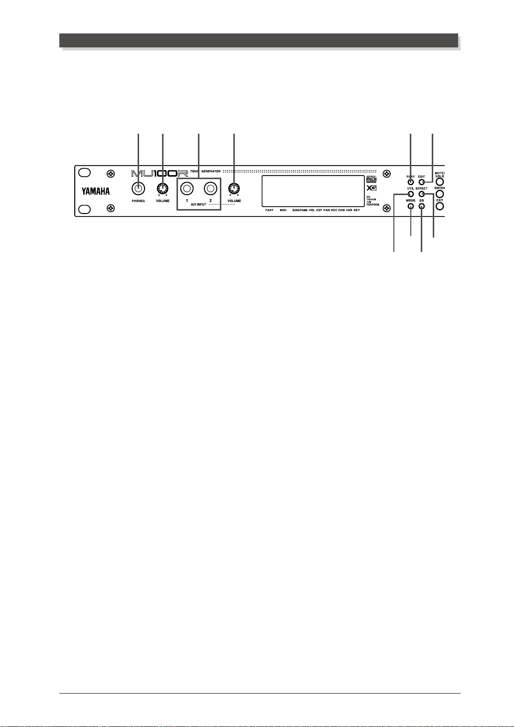
The Controls of the MU100R
Front Panel
1324 58
1 PHONES jack
For connection to a set of stereo headphones (1/4” plug).
The Controls of the MU10 0R
7
9
6
0
2 VOLUME control
For adjusting the overall volume of the MU100R.
3 A/D INPUT 1, 2 jacks
For connection of a microphone, electric guitar or other electronic instruments
(mono 1/4” plugs).
4 A/D INPUT VOLUME control
For control of the level of the A/D inputs.
5 PLAY button
For entering the Play mode and switching among the different Play displays.
(See page 24.)
6 UTIL (UTILITY) button
For entering the Utility mode. (See page 15.)
7 MODE button
For entering the Sound Module mode. (See page 23.)
8 EDIT button
For entering the Edit mode. (See page 36.)
9 EFFECT button
For entering the Effect Edit mode. (See page 74.)
: EQ button
For entering the EQ Edit mode. (See page 82.)
The Controls of the MU90R
1
Page 13

The Controls of the MU100R
GHA
D
POWER
ON/ OFF
C
B
E
F
A MUTE/SOLO button
Pressing this alternately mutes or solos the selected Part. (See page 85.)
B ENTER button
For calling up menu items in the display and for executing certain functions
and operations. Double-clicking this (pressing it twice quickly) calls up the
Show Exclusive function (see page 175).
C EXIT button
For leaving various display pages and returning to previous displays. Also for
canceling certain functions and operations.
D PART -/+ buttons
For selecting different Parts. In the Effect Edit mode, these can be used to
switch among the different effects. Pressing these together alternately switches
between All Part and Single Part control. (See page 48.)
E SELECT </> buttons
For selecting the various menu items, parameters and controls on the display.
F VALUE -/+ buttons
For changing the value of a selected parameter or control.
Hint
You can rapidly move through the values by holding down one of the [VALUE
buttons. You can move even more rapidly by holding down one button and then pressing and holding down the other. For example, to rapidly advance (increase) the value,
+
hold down the [VALUE
-
] button.
] button and simultaneously press and hold down the [VALUE
G Data dial
For rapidly adjusting/changing values of the selected function or parameter.
Rotate this clockwise to increase the value.
H POWER switch
Pressing this turns the power on and off.
2
The Controls of the MU90R
-/+
]
Page 14
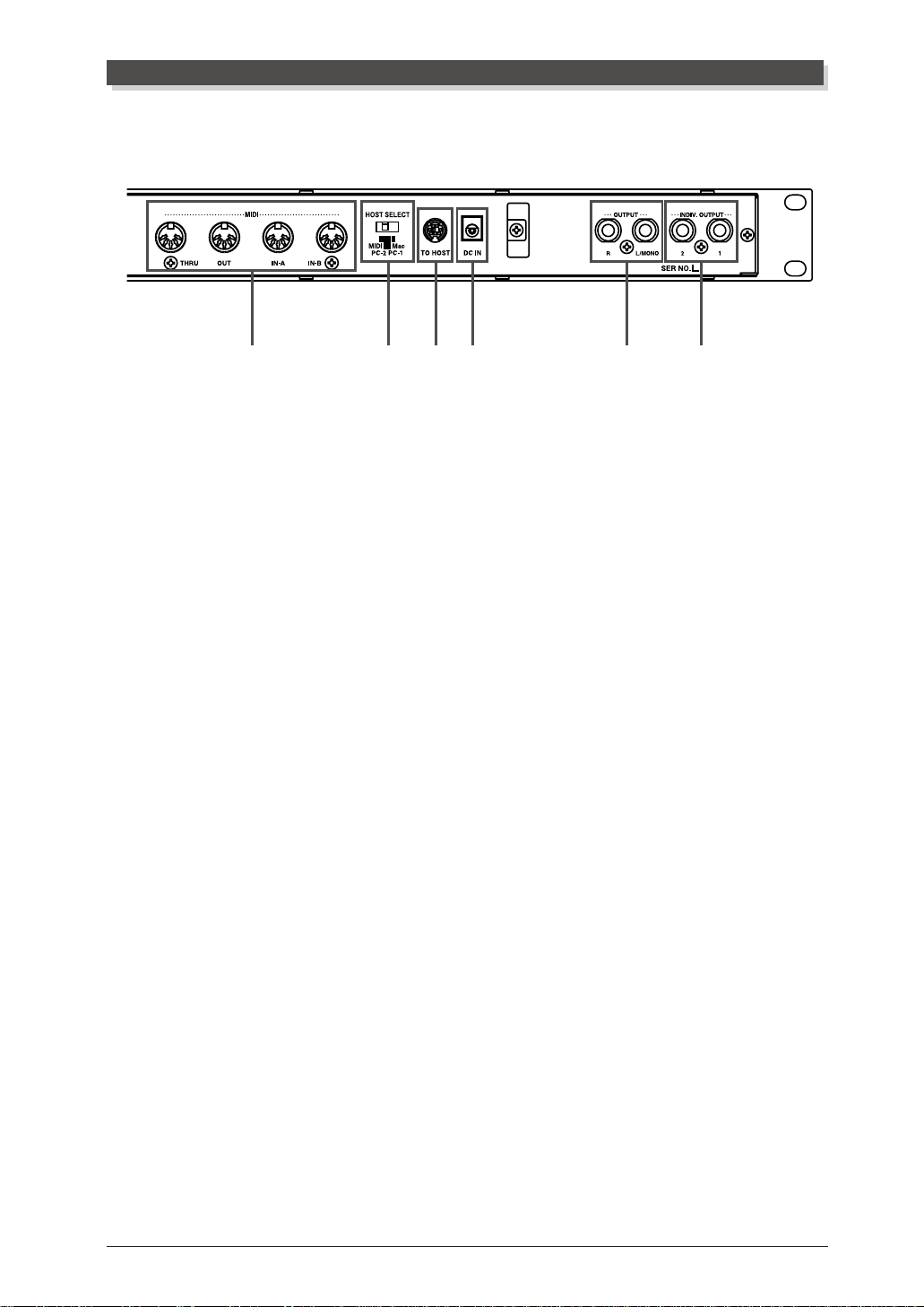
Rear Panel
1 MIDI THRU, MIDI OUT and MIDI IN A/B terminals
For connection to other MIDI devices, such as a MIDI keyboard, tone generator, sequencer, or to a computer that has a MIDI interface. MIDI IN A and B
are independent MIDI ports, allowing full 32-channel MIDI input. MIDI OUT
is for data dumps to another MIDI device, while MIDI THRU is for “daisychain” connection of additional MU100Rs or other MIDI instruments. (See
page 17 for more information on MIDI connections.)
The Controls of the MU10 0R
543216
2 HOST SELECT switch
For selecting the type of host computer. (See page 19.)
3 TO HOST terminal
For connection to a host computer that does not have a MIDI interface. (See
page 19.)
4 DC IN jack
For connection to the PA-5B AC power adaptor.
5 OUTPUT R, L/MONO jacks (Right, Left/Mono)
For connection to a stereo amplifier/speaker system. When using a mono system, connect it to the L/MONO jack.
6 INDIV. (Individual) OUTPUT 1, 2 jacks
For independent output of selected Parts (1/4” jack). Parts selected for output
through these jacks are not output through the main OUTPUT or PHONES
jacks. (See pages 113 and 118.)
The Controls of the MU90R
3
Page 15

The M U100R — What It I s and What It Can Do
The MU100R — What It Is and What It Can Do
What It Is...
The MU100R is a full-featured and easy-to-use tone generator, that provides an
unprecedented wealth of Voices and expressive sonic control. It features full
General MIDI Level 1 compatibility with 128 General MIDI Voices and 9 drum
kits. It also provides new XG-MIDI (Extended General MIDI) compatibility,
with an huge total of 1074 Voices and 36 drum kits. Moreover, it has an integrated VL tone generator that provides 256 stunning monophonic Voices utilizing Yamaha’s sophisticated V irtual Acoustic Synthesis system.
The MU100R has 64-note polyphony and is 32-Part multi-timbral. In other
words, the MU100R has 32 different Parts, each with its own Voice, so that up to
32 different Voices can be sounded simultaneously . Since the MU100R features
dual MIDI input ports (A and B), 16 Parts can be played from one MIDI port and
the remaining 16 from the other port.
Additional A/D Parts let you connect up to two external signals — such as a
microphone, electric guitar or CD player — and mix them with the MU100R’s
Voices.
The MU100R also has a TO HOST terminal for easy interfacing with a computer, allowing you to play the Voices using your favorite music software. This
is where the advanced multi-timbral capabilities come in, letting you playing
sophisticated arrangements using up to 32 different Voices at the same time.
Although Voices cannot be directly edited, the various Part controls and Edit
mode give you tools for transforming or customizing the sound of the Voices.
What’s more, the MU100R has a built-in multi-effect processor, with seven independent digital effect “units” for enhancing the sound. Included in these is a
powerful Harmony section that allows you to generate realistic vocal harmonies
with your actual voice (using one of the A/D Parts).
The MU100R also features a special Performance mode, in which four Parts
are played simultaneously over a single MIDI channel. Connected to a MIDI
keyboard, this effectively gives you four tone generators in one. The MU100R
gives you 100 factory-programmed Preset Performances plus 100 Internal Performance locations for storing your own original Performances.
About General MIDI
General MIDI is a new addition to the worldwide MIDI standard. MIDI, as
you know, stands for Musical Instrument Digital Interface, and makes it
possible for various electronic musical instruments and other devices to “communicate” with each other. For example, by connecting a sequencer to the
MU100R’s MIDI IN terminal, you could play back a song on the sequencer
using the Voices of the MU100R.
4
The MU100R — What It Is and What It Can Do
Page 16

So, where does General MIDI fit in all of this? One of the most important
features of General MIDI is in the standardization of Voices. This means that a
song recorded in the General MIDI format can be played back on any General
MIDI compatible tone generator and sound just as the composer intended. For
example, if there is an alto sax solo in the song, it will be played by an alto sax
Voice on the General MIDI tone generator (and not by a tuba or harpsichord!).
Since the MU100R is fully compatible with General MIDI, you can take advantage of the vast wealth of musical material recorded in that format.
About XG-MIDI
The new XG format is an extension of General MIDI, and provides a number of
significant improvements and enhancements. XG-compatible song data takes
advantage of the extensive MIDI control and built-in effects of the MU100R
(and other MU-series instruments).
T o take greatest advantage of the powerful capabilities of XG-MIDI, we recommend using XG-compatible instruments and software. For example, XGcompatible keyboards such as the Yamaha CBX-K1 keyboard and software give
you direct controls for accessing the full expressive potential of the MU100R’ s
XG Voices and the XG-related parameters.
The M U100R — What It I s and What It Can Do
What It Can Do...
Here are a few ideas on how you can use the MU100R. The list below is not
comprehensive, but is meant to be a general guide to the possibilities and provide a starting point or springboard for your own creative ideas and explorations.
Using With MIDI Keyboard
Use the MU100R as supplementary tone generator with your MIDI keyboard and play the Voices of both instruments in a layer together. Or , use the
convenient Performance mode, and play four Voices on the MU100R at once.
You can split the four Voices across the keyboard, playing each from a different register. Or you can create sophisticated velocity splits, in which a
different Voice is heard depending on how strongly you play the keyboard.
Or use keyboard and velocity splits together for even greater flexibility.
Using With a Computer or Sequencer
Home Studio Setup
The MU100R integrates instantly and easily into any existing setup. If you have a
MIDI keyboard, computer and sequencing software, the MU100R with its highquality Voices and multi-timbral capabilities can expand your home studio system.
The MU100R — What It Is and What It Can Do
5
Page 17

The M U100R — What It I s and What It Can Do
Carry It With You
If you have a laptop computer (and sequencing software), simply connect the
MU100R, plug in some headphones and you’ve got a complete, high-powered
music making system that’ s ready to go wherever you go. Use it for composing,
arranging, practicing or making/playing demos for your band.
Use It on a Gig
Similarly , you can connect a laptop or a MIDI data filer and playback song data with
the MU100R’s Voices. Plug a microphone into one of the A/D inputs and a guitar
into the other, and you can mix your own live performance with the sequencer tracks.
What’s more, you can produce automatic vocal harmonies with the Harmony ef fect
— controlled either from a keyboard or directly from one of the sequencer tracks!
Multimedia
Since it’s compatible with General MIDI and XG, the MU100R is a natural for
multimedia applications. Bring it with you to a presentation — since the computer interface is built-in to the MU100R, it hooks up instantly and easily to the
computer’s serial port or printer port, without the need for any other equipment.
About the Modes of the MU100R
The MU100R has two main operating modes: Multi and Performance. In
Multi mode, the MU100R is a 32-Part multi-timbral tone generator; in Performance mode, the MU100R effectively functions as four tone generators
controlled over a single MIDI channel.
Which mode the MU100R is in depends on the selected Sound Module
mode. If XG, TG300B or C/M are selected, the MU100R automatically sets
itself to the Multi mode. When PFM is selected, the MU100R is in the Performance mode. (For information on selecting the Sound Module mode, see
page 172.)
Each mode provides compatibility with different music software and hardware.
XG: This stands for Extended General MIDI and provides the full
potential of the MU100R, giving you access to the 1074 XG Voices
plus the VL Voices.
TG300B: This mode provides compatibility with the GM-B mode of the
TG300 T one Generator.
C/M: This mode provides compatibility with most computer music soft-
ware not supported by the other two Multi modes.
PFM: This mode (Performance) lets you play four Voices simultaneously
over a single MIDI channel. (For more information on using the
Performance mode, see page 43.)
6
The MU100R — What It Is and What It Can Do
Page 18

The M U100R — What It I s and What It Can Do
The bottom right of the display indicates the currently selected Sound Module mode.
Selected Sound Module mode.
NOTE
When set to the TG3 0 0 B mode, the MU100R may not be able to play TG300-specific song data with complete accuracy. However, MIDI data designed for other
computer music tone generators is compatible with the MU100R.
Play Modes and the Part Controls
XG
TG300B
C/M
PERFORM
Once the operating mode of the MU100R is set (Multi or Performance),
there are two main ways you can use the MU100R: playing and editing. In
the Play modes, you play the Voices; in the various Edit modes, you change
their settings.
Within the Play modes are the Part controls. These let you make basic
settings for the Parts. The Single Part controls allow you to make independent settings for each Part, while the All Part controls allow you to change
the overall settings of all Parts. (See pages 96 and 98 for more information.)
The MU100R has several different Edit modes, each with various menus
and operations:
Part Edit Mode
The Part Edit mode allows you to change certain settings for each individual
Part, such as those of the Filter, EG (Envelope Generator), and many other
settings. The internal Voices can be sounded during editing, allowing you to
hear the effects of your edits.
Utility Mode
The Utility mode lets you set functions related to the overall operation of the
MU100R, such as Master Tune, display Contrast and reception of certain
MIDI messages that affect the entire instrument. Included also are miscellaneous operations, such as sending bulk data to a data storage device, initializing of the MU100R settings, and playing the special Demo song.
The MU100R — What It Is and What It Can Do
7
Page 19
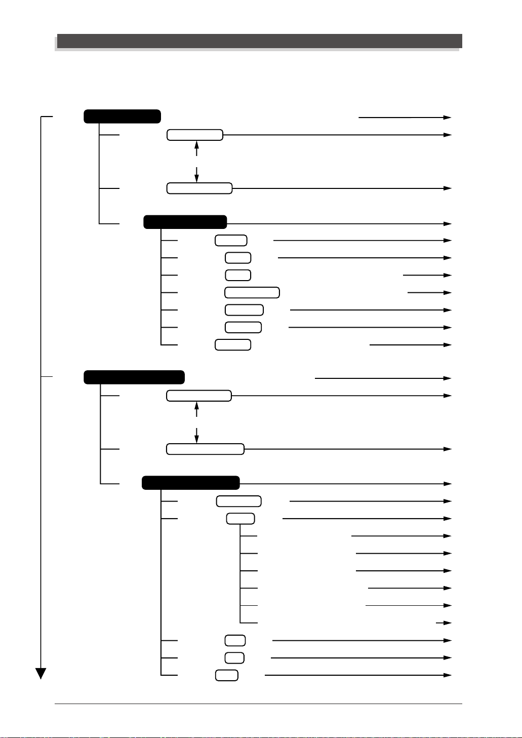
Modes and Function Tree
Modes an d Func tion Tree
[PL AY]
[PL AY]
Multi Play Mode
[SELECT </>] Multi Part Control
[SELECT </>] Multi All Part Control
[EDIT]
( When the sound module mode is “XG”, “TG300B”, or “C/M”)
[PART++-]
Multi Par t Edit Mode
[SELECT <] Filter Edit [ENTER]
[SELECT </>] EG Edit [ENTER]
[SELECT </>] EQ Edit (Only when Normal or VL Part is selected.) [ENTER]
[SELECT </>] Drum Setup Edit (Only when Drum Part is selected.)
[SELECT </>] Vibrato Edit [ENTER]
[SELECT </>] Others Edit [ENTER]
[SELECT >] Plugin Edit (Only when VL Part is selected.)
Pe rf ormanc e P lay Mode (
[SELECT </>] Performance Control
When the sound module mode is ”PFM”)
[ENTER]
[ENTER]
P. 95
P. 96
P. 98
P. 100
P. 100
P. 102
P. 105
P. 114
P. 106
P. 107
P. 119
P. 127
P. 128
[PART++-]
[SELECT </>] Performance Part Control
[EDIT]
Pe rf ormanc e Edit Mode
[SELECT <] Common Edit [ENTER]
[SELECT </>] Part Edit [ENTER]
[SELECT <] Filter Edit [ENTER]
[SELECT </>] EG Edit [ENTER]
[SELECT </>] EQ Edit [ENTER]
[SELECT </>] Vibrato Edit [ENTER]
[SELECT </>] Others Edit [ENTER]
[SELECT >] Plugin Edit (
[SELECT </>] Copy [ENTER]
[SELECT </>] Store [ENTER]
[SELECT >] Recall [ENTER]
8
The MU100R — What It Is and What It Can Do
Only when VL Part is selected.
) [ENTER]
P. 129
P. 131
P. 131
P. 134
P. 135
P. 135
P. 135
P. 135
P. 135
P. 136
P. 137
P. 138
P. 140
Page 20
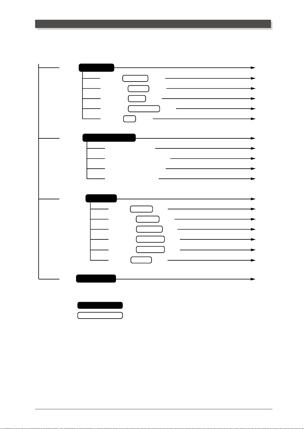
Modes and Function Tree
[UTIL]
[MODE]
[EFFECT]
Utility Mode
[SELECT <] System Setup [ENTER]
[SELECT </>] Dump Out [ENTER]
[SELECT </>] Initialize [ENTER]
[SELECT </>] Demo Song Play [ENTER]
[SELECT >] Plugin [ENTER]
S ou nd Module Mode
[SELECT <] or [VALUE-] XG
[SELECT </>] or [VALUE+/-] TG300
[SELECT </>] or [VALUE+/-] C/M
[SELECT >] or [VALUE+] PFM
E f fe ct Mode
[SELECT <] Reverb Edit [ENTER]
[SELECT </>] Chorus Edit [ENTER]
[SELECT </>] Variation Edit [ENTER]
P. 156
P. 157
P. 161
P. 165
P. 168
P. 169
P. 172
P. 172
P. 172
P. 172
P. 172
P. 141
P. 142
P. 143
P. 144
[SELECT </>] Insertion 1 Edit [ENTER]
[SELECT </>] Insertion 2 Edit [ENTER]
[SELECT >] Plugin Edit [ENTER]
[EQ]
E qu alizer Mode
: Mode
: Submode
Push on the SELECT buttons either < or > for SELECT < / >.
Push on the PART + and - simultaneously for PART ++ -.
P. 146
P. 146
P. 147
P. 155
The MU100R — What It Is and What It Can Do
9
Page 21

10
The MU100R — What It Is and What It Can Do
Page 22

G
W hen using your M U100R for the first time, read through
this short section of t he manual. It guides you step-by-step i n
using many of the basic operations: setting the instrument up,
connecting it properly t o other equipment, and — most importantly — pl aying it. I t also intr oduces you to most of the
other, advanced features and operations of the instr ument —
enabling you to quickly and effectively get the most out of
your new MU100R.
UIDED
T
OUR
Page 23

Setting Up Your MU100R
Se tting Up You r MU100R
In this section, you’ll learn how to:
© Connect the MU 1 0 0R in t he most basic setup — with a MIDI keyboard
and an external amplifier/speaker system.
Other setup examples are covered in later sections; for example, setting up
for use with a computer is on page 19. Once you’ve set up the MU100R, we
urge you to play the Demo song (page 15) and hear what the instrument is
capable of.
What You’ll Need
☛ The MU100R and the included PA-5B power adaptor.
☛ A MI D I keyboard, electronic piano, or any instrument that can output
MIDI data.
☛ An amplif ier/speaker system, preferably stereo. Alternately, you can use
a set of st er eo headphones.
☛ Audio connecting cables.
☛ A MIDI cable.
Making the Connections
CAUTION!
Before making any connections, turn all related equipment off, and make sure the
MU100R power adaptor is not connected to an electrical outlet.
Operation
1 Connect the MIDI cable.
Connect the MIDI OUT terminal of the MIDI keyboard to the
MIDI IN-A of the MU100R (as shown in the illustration).
2 Connect the audio cables.
Connect the R and L/MONO OUTPUT jacks of the MU100R to
the appropriate inputs on the amplifier speaker system (as shown
in the illustration).
•If the amplifier has only one input, use the L/MONO jack on the
MU100R. If you are using stereo headphones, connect them to
the front panel PHONES jack.
12
Guided Tour
Page 24
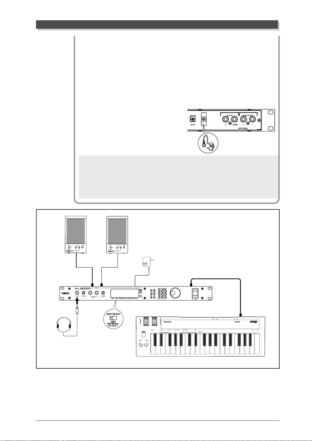
Setting Up Your MU100 R
3 Set the HOST SELECT switch.
Set this rear panel switch to MIDI (see illustration).
4 Connect the AC power adaptor.
Plug the DC output cable of the PA-5B into the DC IN terminal
on the rear panel, then plug the adaptor into an appropriate
electrical outlet.
•Wrap the DC output cable of
the adaptor around the cable
clip (as shown below) to prevent accidental unplugging of
the cable during operation.
CAUTION!
• Do not attempt to use an AC adaptor other than the PA-5B. The use of an incompatible adaptor may result in irreparable damage to the MU100R, and even
pose a serious shock hazard.
• Be sure to disconnect the power adaptor from the outlet when the MU100R is
not in use.
PHONES
Amplifier
Speaker System
R
Power
Adaptor
DC INL/MONO
OCTAVE SHIFT
MIDI IN-A
POWER
ON/ OFF
MIDI OUT
DRUM
NUMBER
(RPN)
120 PITCH BEND SENSITIVITY
121 FINE TUNING
122 COARSE TUNING
(NRPN)
123 VIBRATO RATE
124 VIBRATO DEPTH
125 VIBRATO DELAY
TRANSPOSE
IN MIDI OUT
126 FILTER CUTOFF FREQUENCY
127 FILTER RESONANCE
128 EG ATTACK TIME
129 EG DECAY TIME
130 EG RELEASE TIME
131 DRUM FILTER CUTOFF FREQUENCY
132 DRUM FILTER RESONANCE
133 DRUM EG ATTACK RATE
134 DRUM EG DECAY RATE
135 DRUM PITCH COARSE
136 DRUM PITCH FINE
137 DRUM LEVEL
138 DRUM PAN
139 DRUM REVERB DEPTH
140 DRUM CHORUS DEPTH
141 DRUM VARIATION DEPTH
CONTROLLER NUMBER LIST
CONTROL CHANGE
11 EXPRESSION
1 MODULATION DEPTH
2 BREATH CONTROL
4 FOOT CONTROL
5 PORTAMENTO TIME
6 DATA ENTRY
7 MAIN VOLUME
ASSIGNABLE
STOP CONTINUE START
8 BALANCE CONTROL
10 PANPOT
PROGRAM RESET SYSTEM WHEEL ASSIGNSEQUENCER
PROGRAM
BANK
CHANGE
TEMPO
SELECT
PITCH
SHIFT
OCTAVE
OCTAVE
RESET
73 ATTACK TIME
64 HOLD1(DAMPER)
74 BRIGHTNESS
65 PORTAMENTO
84 PORTAMENTO CONTROL
66 SOSTENUTO(CHORD HOLD)
91 REVERB DEPTH
67 SOFT PEDAL
92 TREMOLO DEPTH
69 HOLD2 (FREEZE)
93 CHORUS DEPTH
71 HARMONIC CONTENT
94 VARIATION DEPTH
72 RELEASE TIME
95 PHASER DEPTH
MIDI
GMONXG
SOUND
MERGE
FIXED
CONTROLLER
NRPN
RPN
CH
ON
OFF
ON/OFF 1 2 3 4 5 6 7 8 9 A B C D E F 0
VELOCITY
MIDI CABLE
POWER ON OFF
DC IN
OTHERS
142 CHANNEL PRESSURE
143 POLYPHONIC KEY PRESSURE
144 MASTER VOLUME
145 MASTER BALANCE
146 MASTER TUNING
147 VELOCITY
148 TEMPO
MIDI KEYBOARD CBX-K1
ENTER
HEXA
DECIMAL
DECIMAL
MIDI Keyboard
Now that you’ve set up the MU100R, we urge you to go on to the next
section, turn on the instrument, and play the Demo song (page 15) to hear
what the instrument is capable of. If you need information on setting up the
MU100R for a different type of system, refer to “Setting Up the MU100R
in Your Music System” on page 17.
Guided Tour
13
Page 25
Powering Up
Powering Up
Admittedly this is a simple operation, but you should be careful to follow the
instructions below to avoid possible damage to your equipment and speakers.
Operation
1 Turn on the power of your MIDI keyboard.
2 Turn on the power of the MU100R.
Press the POWER switch.
After the animated greeting display finishes, the following display appears:
3 Turn down all volume controls.
This includes the MU100R and any connected equipment.
4 Turn on the amplifier/speaker system.
5 Set the volume controls.
First, set the volume control on the MU100R to about the midway position, then set the volume on the amplifier to a suitable
level.
Power ing Down
When you turn the power off, make sure to do it in the following order:
1) Amplifier/speaker system
2) MU100R
3) Other connected equipment (MIDI keyboard, etc.)
This prevents possible damage to the speakers.
14
Guided Tour
Page 26
Playing the De mo Son g
Now that you’ve set everything up properly, try playing the built-in Demo
song. This showcases the high-quality Voices and the AWM2 tone generation system of the MU100R. It also is an excellent demonstration of the 32part multi-timbral capacity and the various expressive controls and effects
that can be used simultaneously . Most importantly , the Demo song will give
you an idea of how powerful the MU100R can be in your own MIDI/computer music setup.
Operation
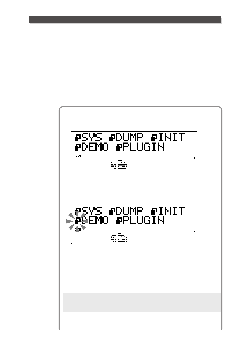
1 Press the [UTIL] button.
Playing the Demo Song
2 Select and open the DEMO menu.
Use the [SELECT -/ >] buttons to select “DEMO” (the menu
icon flashes), then press the [ENTER] button.
3 Start the Demo song.
Press the [ENTER] button. The Demo Song starts playing imme-
diately and repeats indefinitely until stopped (in step 4 below).
Playback of the individual Parts of the song is shown graphically
by the “level meter” bars in the display.
NOTE
During Demo Song playback, none of the panel controls (with the exception of
EXIT] button and the VOLUME control) can be used.
the [
Guided Tour
15
Page 27

Playing the Demo Song
4 Stop playback of the song.
Press the [EXIT] button.
5 Exit from the Demo Song function.
Press the [EXI T] button again — twice to return to the Play
mode. (Or you can simply press the [PLAY] button.)
16
Guided Tour
Page 28
Setting Up the MU100 R in Your Music System
Se tting Up the MU100R in Your Music Sy stem
As you learned in the section The MU100R — What It Is and What It
Can Do on page 4, the MU100R can be integrated into a variety of setups. It
would be impossible to cover all connection possibilities in a short manual
as this; however, the section below will help in quickly setting up the MU100R
and using it in your system.
Connecting to MIDI Devices
The MU100R is equipped with MIDI IN, OUT , and THRU terminals, allowing you to use it in any MIDI system. Moreover, the two MIDI IN terminals
are independent 16-channel ports, effectively giving you two tone generators in one. Here are some common connection examples using the built-in
MIDI interface. Refer to the example that most closely matches your setup,
then read the Operation steps at the end of this section.
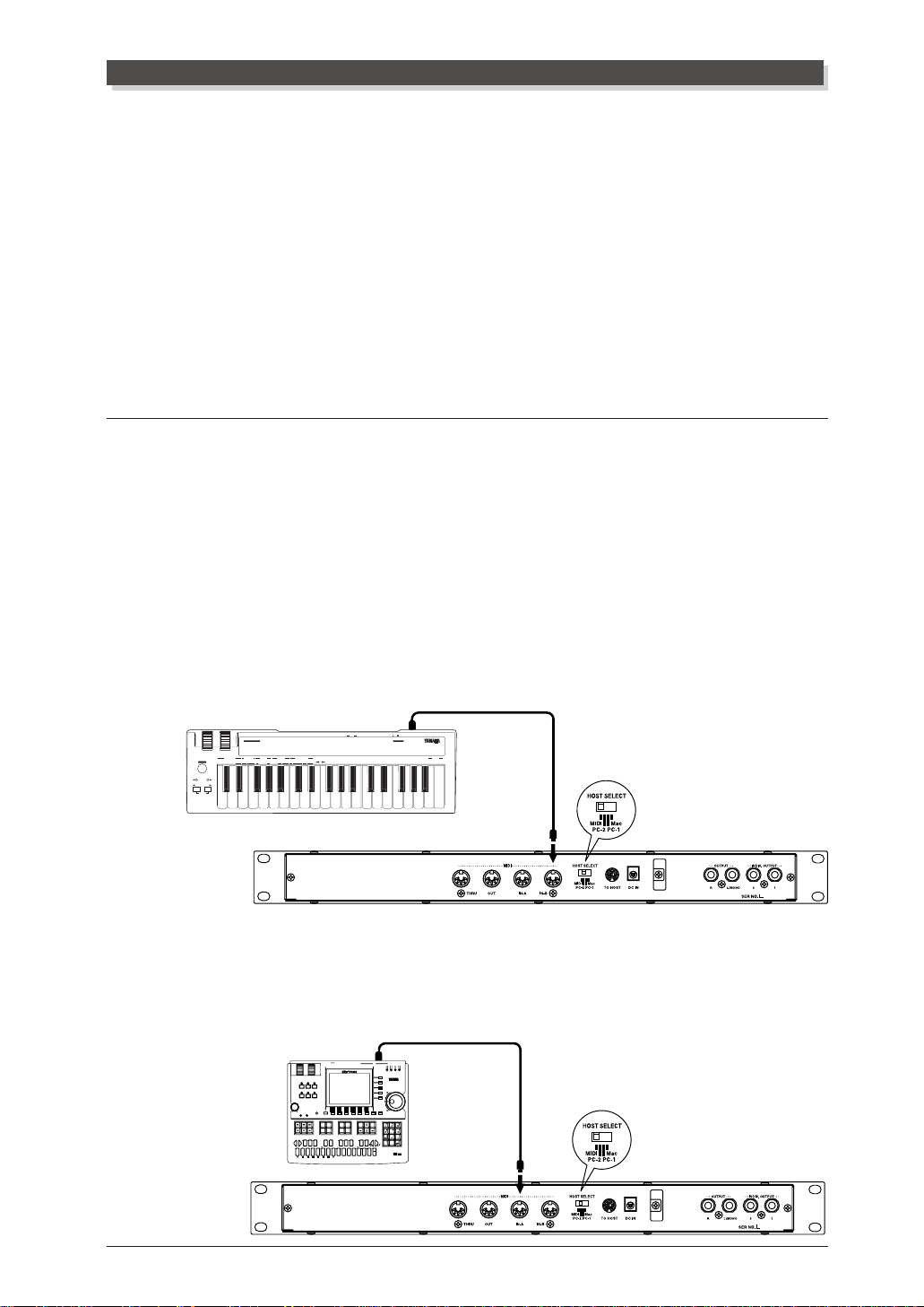
• MIDI keyboard
In this setup, you can play the sounds of the MU100R from the connected
keyboard.
MIDI CABLE
MIDI OUT
DC IN
IN MIDI OUT
CONTROLLER NUMBER LIST
CONTROL CHANGE
73 ATTACK TIME
11 EXPRESSION
1 MODULATION DEPTH
2 BREATH CONTROL
4 FOOT CONTROL
5 PORTAMENTO TIME
6 DATA ENTRY
7 MAIN VOLUME
8 BALANCE CONTROL
PITCH
ASSIGNABLE
10 PANPOT
PROGRAM RESET SYSTEM WHEEL ASSIGNSEQUENCER
PROGRAM
GMONXG
BANK
SOUND
CHANGE
STOP CONTINUE START
TEMPO
SELECT
SHIFT
OCTAVE
OCTAVE SHIFT
OCTAVE
RESET
OFF
(RPN)
120 PITCH BEND SENSITIVITY
74 BRIGHTNESS
64 HOLD1(DAMPER)
121 FINE TUNING
84 PORTAMENTO CONTROL
65 PORTAMENTO
122 COARSE TUNING
91 REVERB DEPTH
66 SOSTENUTO(CHORD HOLD)
(NRPN)
92 TREMOLO DEPTH
67 SOFT PEDAL
123 VIBRATO RATE
93 CHORUS DEPTH
69 HOLD2 (FREEZE)
124 VIBRATO DEPTH
94 VARIATION DEPTH
71 HARMONIC CONTENT
95 PHASER DEPTH
72 RELEASE TIME
125 VIBRATO DELAY
TRANSPOSE
MIDI
FIXED
MERGE
DRUM
CONTROLLER
NRPN
RPN
CH
ON
VELOCITY
ON/OFF 1 2 3 4 5 6 7 8 9 A B C D E F 0
NUMBER
MIDI Keyboard
126 FILTER CUTOFF FREQUENCY
127 FILTER RESONANCE
128 EG ATTACK TIME
129 EG DECAY TIME
130 EG RELEASE TIME
131 DRUM FILTER CUTOFF FREQUENCY
132 DRUM FILTER RESONANCE
133 DRUM EG ATTACK RATE
134 DRUM EG DECAY RATE
135 DRUM PITCH COARSE
136 DRUM PITCH FINE
137 DRUM LEVEL
138 DRUM PAN
139 DRUM REVERB DEPTH
140 DRUM CHORUS DEPTH
141 DRUM VARIATION DEPTH
POWER ON OFF
OTHERS
142 CHANNEL PRESSURE
143 POLYPHONIC KEY PRESSURE
144 MASTER VOLUME
145 MASTER BALANCE
146 MASTER TUNING
147 VELOCITY
148 TEMPO
MIDI KEYBOARD CBX-K1
ENTER
HEXA
DECIMAL
DECIMAL
MIDI IN-A or B
• Hardware sequencer
In this setup, a hardware sequencer (such as the Yamaha QY700) is used.
The main advantage of such a setup is its portability.
MIDI CABLE
MIDI OUT
IN A
OUT BOUT A
IN B
FOOT SWRL/MONO
MIDI
PITCH ASSIGNABLE
SONG
VOICE
MAX
VOLUME
SHIFT
CAPS
OCT
OCT
DOWN
UP
ON
ORG
BASS
BASS
_
E FGAB C
A
SECTION
B C D E F G H
OUTPUT
PATTERN
UTILITY
EFFECT
DISK
SHIFT F1 F2 F3 F4 F5 F6 SHIFT EXIT
CONTRAST
PLAYREC
JOB
EDIT
LOC 2LOC 1
(
♯
♯
E)D
♯
CBA
A
F
C♯D
G
♭
♭
♭
B
G
A
D♭E
c
S
%
?
!
MLK
D
MUSIC SEQUENCER
TRACK
DOWN
REST
♯
♯
(
5)
7
♭
♭
(
5)
7
&
(9)
(9)
add9
6
M7
6
M7
M
OUT BOUT AIN B
IN A
MIDI
-1 +1
TRACK
789
YESNO
UP
456
SOLOMUTE
TIE
123
DEL
SPACE
a
♯
(♭13
)
HGF
JI
9)
(
(11)
-
0
7
7
7
sus4
m7
OCT
OCT
3
3
♯
DOWN
UP
11)
(
(♭9)
(13)
7
7
7
sus4
c
_
/
ZWV
YX
UTSRQPO#N
(9)
(9)
dim
mM7
add9
7
m7
aug
(♭5
)
7
m
m6
m7
m7
MIDI IN-A
Guided Tour
17
Page 29
Setting Up the MU100 R in Your Music System
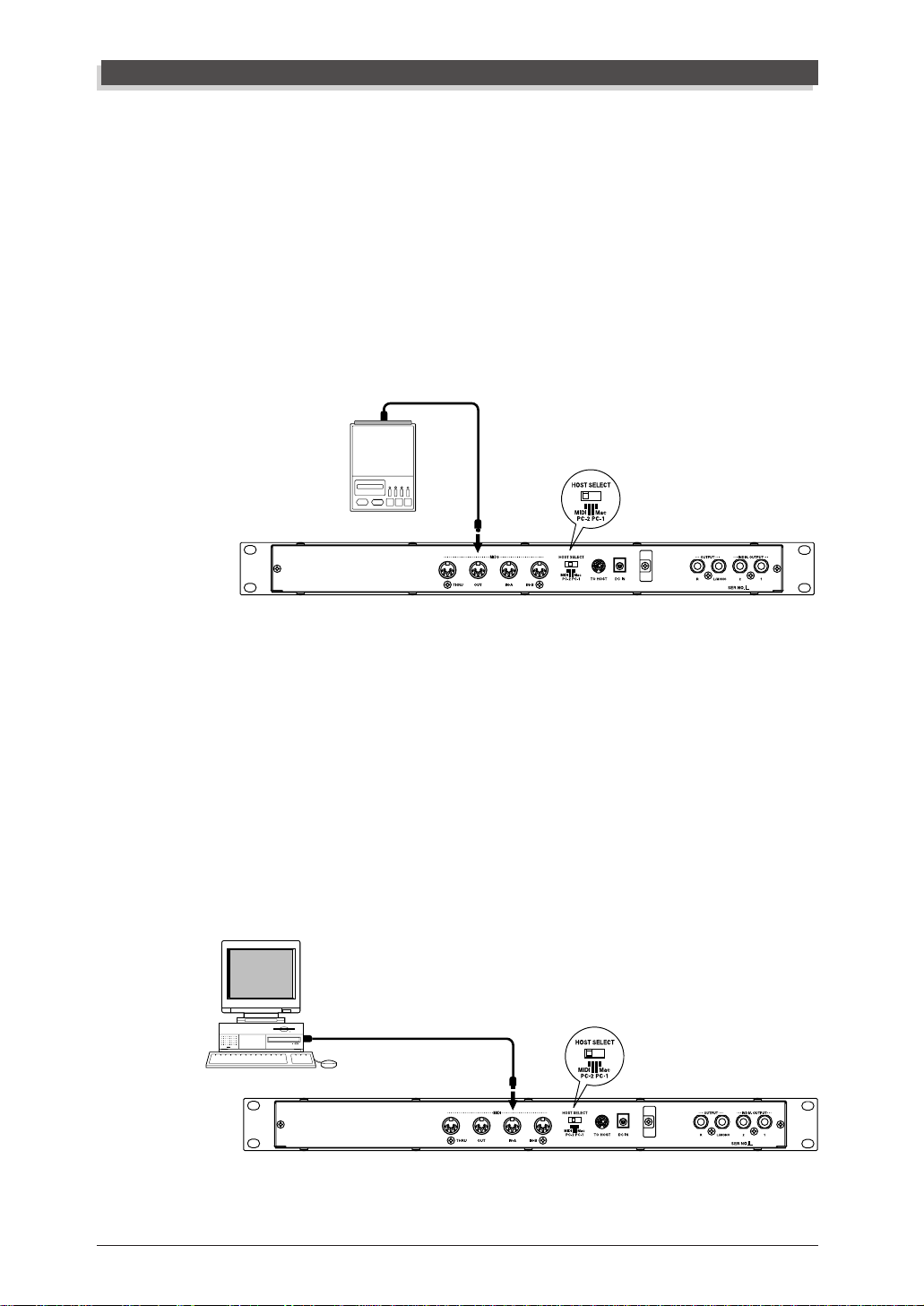
• MIDI data storage device
This setup is used for backing up your important data — including original
Performances you’ve created, as well as settings you’ve changed in the Part
Edit, Effect, EQ, or Utility modes.
In this example, a Yamaha MDF2 MIDI Data Filer is used. To back up
data, connect the MIDI IN of the MDF2 to the MIDI OUT of the MU100R.
T o restore the data to the MU100R, connect the MIDI OUT of the MDF2 to
the MIDI IN of the MU100R. Refer to the owner’s manual of the MDF2 (or
your particular data storage device) for specific operating instructions in
receiving or sending data.
MIDI IN
MDF2
MIDI CABLE
MIDI OUT
With the MDF2, you can also play compatible song data on the MU100R
directly from the MDF2 itself, without the need of a sequencer. In this case,
the MIDI OUT of the MDF2 should be connected to the MIDI IN of the
MU100R.
• Computer equipped with a MIDI interface
In this setup, you can control the MU100R from a computer (using sequencing or other song playback software). In a variation on this, you can connect
the computer to MIDI-A and a keyboard to MIDI-B. This allows you to play
parts live over sequencer playback — even if the sequencer uses all 16 MIDI
channels.
MIDI OUT
Computer
MIDI CABLE
MIDI IN-A
18
Guided Tour
Page 30
Setting Up the MU100 R in Your Music System
Operation
1 Set the HOST SELECT switch to MIDI.
2 Connect the MU100R to the appropriate MIDI device.
Refer to the illustrations above. Use a standard MIDI cable (see
page 92).
3 Turn on the the connected device, then the MU100R.
4 If you are using a computer, start up your music software, and
set up the appropriate options on the software for operation with
the MU100R.
Connecting Directly to a Computer
The MU100R features a built-in host computer interface, allowing you to
directly connect it to your computer — eliminating the need of installing a
special MIDI interface to your computer . The MU100R can be used with the
following computers: Apple Macintosh and compatibles, IBM PC/AT and
compatibles.
If your computer has a MIDI interface you may want to connect the
MU100R to it, rather than using the host computer interface on the MU100R.
(See the section “Connecting to MIDI Devices” on page 17.)
Depending on the computer or interface used, set the HOST SELECT
switch to the appropriate setting: MIDI, PC-1, PC-2 (IBM and compatibles),
or Mac (Macintosh and compaibles). For information on the types of cables
that can be used for connection, see the section “MIDI/Computer Con-
necting Cables” on page 92.
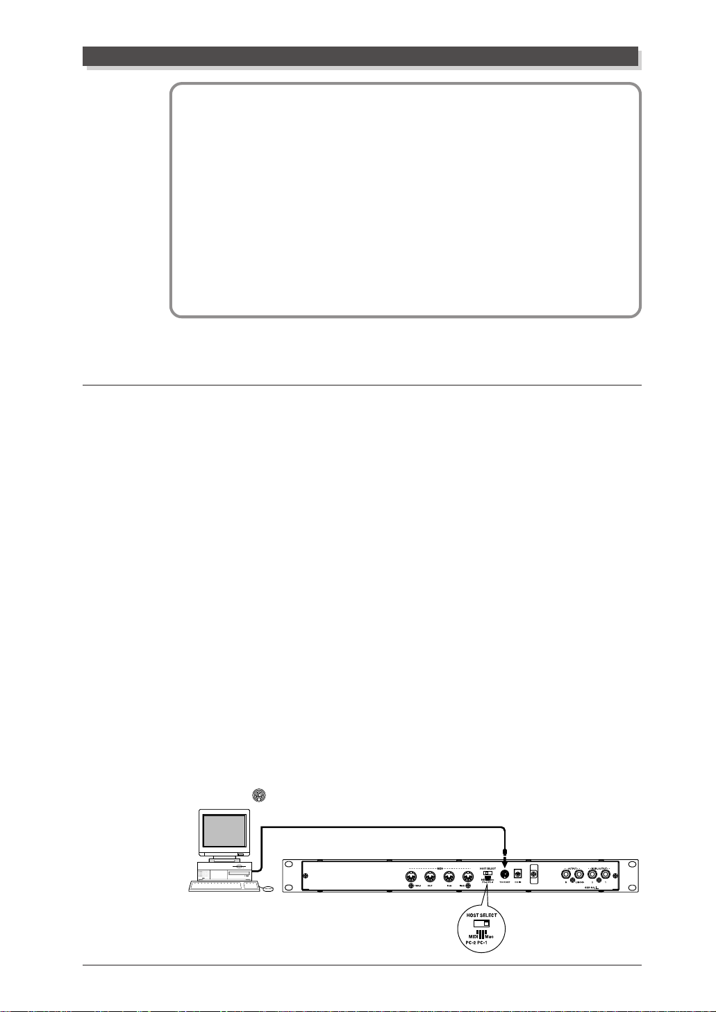
Macintosh and Compatibles
Follow these instructions if you have an Apple Macintosh not equipped with
an external MIDI interface. Connect the TO HOST terminal on the MU100R
to the Modem or Printer port on the Macintosh.
Modem or
Printer Port
Macintosh
Guided Tour
19
Page 31

Setting Up the MU100 R in Your Music System
Operation
1 Set the HOST SELECT switch to Mac.
2 Connect the MU100R to the host computer.
Refer to the illustration above. Use a standard Macintosh cable
(8-pin Mini DIN on both ends; see page 92).
3 Turn on the the host computer, then the MU100R.
4 Start up your music software.
If necessary, set up the appropriate options on the software for
operation with the MU100R. The relevant settings may be found
in menu(s) called “Studio Setup,” “System Setup,” or “MIDI
Setup.”
In this menu, you should be able to set separate MIDI outputs to access the
two MIDI ports on the MU100R. For example, the device for MIDI OUT 1
should be set to “Yamaha MU100” (or “MU80,” if “MU100” is not available).
Other options you may have to set include:
MIDI Interface Type
MIDI Time Piece
Clock
g
Standard MIDI Interface
g
On (for controlling all 32 Parts of the MU100R)
g
1 MHz
(The specific menu/parameter names may differ depending on your particular music software. For detailed instructions, refer to the owner’s manual or
on-line help of the software.)
Hint
If you have a second multi-timbral tone generator (such as the MU50), you can
connect it to the MIDI OUT terminal of the MU100R and have
MIDI ports (for 48-channel operation). The software settings above apply here as
well: Set the device for MIDI OUT 3 to “Yamaha MU50” (or similar). (For more
information, see page 159.)
three independent
20
Guided Tour
Page 32

IBM PC/AT and Compatibles
Follow these instructions if you have an IBM PC/AT or compatible computer not equipped with an external MIDI interface. Connect the TO HOST
terminal on the MU100R to one of the computer’s serial ports, COM 1 or
COM 2.
Serial Port
IBM PC/AT and Compatible
The instructions below assume you are running Windows95 on your PC. For
using the TO HOST connection with other software and operating systems,
consult your Yamaha dealer. If your computer and music software cannot
recognize the TO HOST connection, you can still use the MU100R by installing a MIDI interface (internal card or external) to the computer.
Setting Up the MU100 R in Your Music System
Operation
1 Install the included driver software.
For Windows95
Install the included Yamaha CBX Driver for Windows95.
The driver software is on a floppy disk included with the MU100R.
Make sure to thoroughly read the “A:\MIDIDRV\README_E.TXT”
on the disk. This contains essential information on installing and
setting up the driver to your computer.
For Windows3.1
Install the included Yamaha CBX Driver for Windows3.1.
The driver software is on a floppy disk included with the
MU100R. Make sure to thoroughly read the “A:\IBMPC\
CBXT3.WRI” on the disk. This contains essential information on
installing and setting up the driver to your computer.
2 Set the HOST SELECT switch to PC-2.
3 Connect the MU100R to the host computer.
Refer to the illustration above. Use a standard computer cable
(8-pin Mini DIN to 9-pin D-SUB; see page 92).
4 Turn on the the host computer, then the MU100R.
Guided Tour
21
Page 33

Setting Up the MU100 R in Your Music System
5 Start up your music software.
If necessary, set up the appropriate options on the software for
operation with the MU100R. The relevant settings may be found
in menu(s) called “Studio Setup,” “System Setup,” or “MIDI
Setup.”
In this menu, you should be able to set separate MIDI outputs to access the
two MIDI ports on the MU100R. For example, MIDI OUT 1 should be set
to “Yamaha CBX A Driver” (or “Windows MIDI, Output 1”). Similarly,
MIDI OUT 2 should be set to “Y amaha CBX B Driver” (or “W indows MIDI,
Output 2”).
(The specific menu/parameter names may differ depending on your particular music software. For detailed instructions, refer to the owner’s manual or
on-line help of the software.)
Hint
If you have a second multi-timbral tone generator (such as the MU50), you can
connect it to the MIDI OUT terminal of the MU100R and have
MIDI ports (for 48-channel operation). The software settings above apply here as
well: Set MIDI OUT 3 should be set to “Yamaha CBX C Driver” (or “Windows MIDI,
Output 3”). (For more information, see page 159.)
three independent
Once you’ve set up the MU100R in your system, check that the MU100R is
properly receiving data.
22
Guided Tour
Page 34

Selecting and Playing the Performances
Selecting and Playing the Performances
As pointed out on page 43, the Performances of the MU100R let you play
four Voices together over one MIDI channel. These specially programmed
Performances (100 Preset and 100 Internal) take full advantage of the
MU100R dynamic Voices and flexible editing functions — giving you exceptionally powerful and expressive sounds for live performance situations.
In this section, you’ll learn how to:
© Call up the Performance mode.
© Select and play Performances.
Calling Up the Performance Play Mode and
Playing the Performances
Operation
1 Press the [MODE] button.
2 Select “PFM” (PERFORMANCE) in the display.
Use the [SELECT -/>] buttons, [VALUE -/+] buttons or data
dial.
XG
TG300B
C/M
PERFORM
Indicates Performance mode.
The Performance mode setting is also shown by the arrow at the
bottom right of the display.
NOTE
For more information on the sound module modes, see page 6.
Guided Tour
23
Page 35

Selecting and Playing the Performances
3 Press the [PLAY] button to go to the Performance Play mode.
You can press the [EXIT] button for this as well.
“All” and keyboard player icon indicate All Part display
of Performance Play mode.
If the All Part display above (with the keyboard player icon) is not
shown, press both [PART-/+] buttons simultaneously.
4 Select the desired bank of Performances — Preset or Internal.
Use the [SELECT </ >] buttons to select the Bank parameter,
then use the [VALU E -/+] buttons to select the desired bank,
Preset (Pre) or Internal (Int).
• Preset bank
The upper body of the keyboard player icon is black,
indicating the Preset bank.
• Internal bank
The upper body of the keyboard player icon is
white, indicating the Internal bank.
24
Guided Tour
Page 36

Selecting and Playing the Performances
5 Select the desired Performance.
Use the [SELECT </ >] buttons to select the Program Number
parameter, then use the [VALU E -/ +] buttons or data dial to
select the desired Performance number.
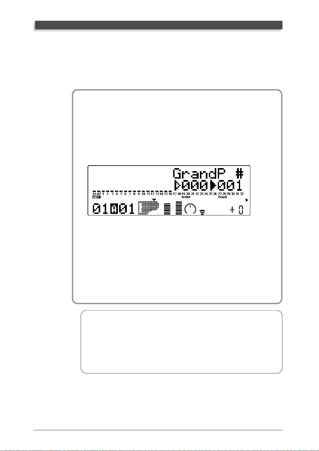
Performance number
6 Play the connected MIDI keyboard.
Make sure that your keyboard is transmitting over MIDI channel
1. (Refer to the owner’s manual of that instrument if necessary.)
If you’ve carefully followed all instructions up to now, the “level
meter” bars in the display should move — and you should be
able to hear the sound of the MU100R as you play.
The “level meter” bars indicate the “level” (velocity) of the incoming MIDI data.
These numbers indicate the four Parts of the Performance.
Go on to select other Performances in the same bank and play those
as well. To try out Performances in the other bank, return to step #4
above.
Guided Tour
25
Page 37

Selecting and Playing I ndividual Voices
Selecting and P laying Individual Voices
The MU100R has a stunningly huge variety of Voices — a total of 1267. In
this section, you’ll select and play Voices in the XG mode, which features
1074 different Voices. The MU100R also features a built-in VL tone generator that provides 256 Voices using the sophisticated Virtual Acoustic Synthesis system (page 63).
In this section, you’ll learn how to:
© Call up the XG m ode.
© Select Voice banks and Voices from the panel controls.
© Change the Play mode display to suit your preference.
© Select and play Voices f rom a MIDI keyboard.
Calling Up the XG Mode
Operation
1 Press the [MODE] button.
2 Select “XG” in the display.
Use the [SELECT </>] buttons, [VALUE -/+] buttons or data
dial.
XG
TG300B
C/M
PERFORM
Indicates XG mode.
The XG mode setting is also shown by the arrow at the bottom right
of the display.
3 Press the [PLAY] button to go to the Play mode.
You can press the [EXIT] button for this as well.
26
Guided Tour
Page 38

Selecting and Playing I ndividual Voices
About the Modes — Mult i and Performance
The MU100R has two main operating modes: Multi and Performance. You
used the Performance mode earlier when playing Performances — playing
four Voices over one MIDI channel. The Multi mode is primarily used in
sequencer and computer music applications, since it allows you to play all 32
Parts independently over different MIDI channels.
Which mode the MU100R is set to depends on the selected Sound Module
mode. The XG, TG300B and C/M settings are all Multi mode. When PFM is
selected, the MU100R is in the Performance mode.
Selecting Voice Banks and Voices From the Panel
O peration
1 Select a Part.
Use the [PART -/+] buttons. Depending on the selected Part,
one of the displays below will appear:
• For Parts 1 – 16 and the A/D Parts:
• For Parts 17 – 32:
For this example, select Part 1. Press the appropriate button until
“01” appears in the PART section of the display.
Guided Tour
27
Page 39

Selecting and Playing I ndividual Voices
2 Select the bank number.
Use the [SELECT </ >] buttons to highlight the bank number
parameter (as shown below).
Instrument icon. Arrow at top
left of icon indicates bank
number is selected.
Bank number. Dark arrow
indicates bank number is
selected.
Program number.
3 Change the bank number.
Use the [VALU E -/ +] buttons or data dial. Notice that the
bank numbers “jump” as they are selected — the MU100R skips
bank numbers that have the same Voice as bank “000.”
In the XG mode, several banks of Voices are available. Each bank
contains up to 128 different Voices, for a total of 1074 Voices.
4 Select the program (Voice) number.
Use the [SELECT </ >] buttons to highlight the program
number parameter (as shown below).
28
Guided Tour
Page 40

Selecting and Playing I ndividual Voices
Instrument icon, indicating the type of
Voice. Arrow at top right of icon indicates program number is selected.
Bank number.
Program number. Dark arrow
indicates program number is
selected.
5 Change the program number.
Use the [VALUE -/+] buttons or data dial. In the example dis-
play below, Voice number 25 has been selected.
6 Play the Voice.
Play this new Voice from the connected MIDI keyboard. (Make
sure that the keyboard is transmitting on channel 1.) If you’ve
carefully followed all instructions up to now, the “level meter”
of the Part should move — and you should be able to hear the
sound of the MU100R as you play. Try selecting other Voice
banks and Voices and play them as well. Each Voice bank contains some different Voices, some of which are variations, some
unique.
D etails
• The MU100R’s Voices and program numbers follow the GM (General MIDI)
format. This means that you can select a Voice type by its number, then select
Voice variations by bank. For example, all the nylon guitar Voices are at program number 25.
• In the XG mode, the Voices are conveniently organized in the banks according
to their type. For example, Voices having stereo variations or brighter variations
are found in the “Stereo” and “Bright” banks, respectively. (See the “Sound List
& MIDI Data” booklet.)
• Banks MSB 48, 46 and above feature Voices that are not simply variations, but
use different instrument samples. (See the “Sound List & MIDI Data” booklet.)
Guided Tour
29
Page 41

Selecting and Playing I ndividual Voices
• Notice that as you increase the bank number, at some point beyond the XG
Voice banks (above bank 127) the bank number returns to “000” and the following icon appears in the display:
Banks showing this icon are MU100 Exclusive Voice banks, and are different
than the same numbered XG Voice banks. (See the “Sound List & MIDI Data”
booklet.)
• VL Voice banks may also be selected if VL Voice selection for the Part has been
enabled. (See page 69.)
• Though the MU100R skips over bank numbers with identical Voices (see step
#3 above), it can be set to not skip bank numbers, if desired. (See page 160:
Utility mode/System/Display Bank Select.)
Changing the Play Mode Display
The MU100R lets you view the Parts in three ways, depending on your preference.
Press the [PLAY] button repeatedly.
Each press of the [PLAY] button switches among the three displays below.
1) Full level meters
This shows the level meters at their maximum height,
but only displays half of the Parts.
2) All Parts, with half level meters
This displays all Parts, but the level meters are at half the height.
3) All Parts, with full level meters
This displays all Parts with the level meters at maximum height.
However, the Voice name and number are not displayed.
30
Guided Tour
Page 42

Selecting and Playing I ndividual Voices
Selecting Voices From a MIDI Keyboard
Y ou can also select Voices remotely from a connected MIDI keyboard. Though
the actual operation may differ depending on the keyboard used, the general
procedure is the same. These instructions also apply to use with a computer .
(Refer to the owner’s manual of your specific instrument or software for
detailed instructions.)
Operation
1 Make the necessary settings on the keyboard.
Make sure that the keyboard is set to transmit over the desired
MIDI channel (the same as that of the selected Part), and that it
is set up to send Program Change messages.
2 Select a program number on the keyboard.
The Voice number and name on the MU100R will change, and
will be the same number as the program number you selected
on your keyboard.
Details
• Depending on what keyboard you are using to control the MU100R, you may
need to be careful in selecting program numbers. The MU100R’s program numbers start at “001,” but some keyboards have different numbering systems. For
example, some start at “0” — which means that selecting “25” on the keyboard
will select Voice 026 on the MU100R.
• Part 10 is reserved for playing drum “kits.” This is the default factory setting for
all of the Multi modes (XG, TG300B, and C/M). For more information on drum
Parts, see page 39.
Guided Tour
31
Page 43

Editing in the Multi Mode
Editing in the Multi Mode
This section takes you step-by-step through an example editing session in
the Multi mode. The operations and techniques you learn here enable you to
perform any editing operation in the Multi mode.
There are two separate sections of the Multi mode that are devoted to
editing: the Single/All Part controls, and the Edit menus.
In this section, you’ll learn how to:
© Select a Part for editing.
© Use the Single P art controls — to change the MIDI channel of a Pa rt, and
change its Volume and Pan settings.
© Use the Edit menu parameters — to change the fil ter and EG ( Envelope
Generator) settings of a Part.
© Use the D rum Setup controls — t o edit change t he Part setti ngs for a
drum kit.
Hints
• Editing Parts, not Voices
It is important to remember that in editing you are not changing the Voice itself,
but rather the Part the Voice is assigned to. This means that when you change the
Voice of the Part, the edited settings apply to the new voice, whether they’re
appropriate or not.
You can use this to your advantage by recording all Multi settings to your sequencer, before the actual song data. This lets you instantly reconfigure the
MU100R and all its settings for each song.
• Saving your edits
Keep in mind that any edits you make in the Multi mode are automatically saved
as the power on defaults. In other words, the next time you turn on the power, the
previous condition of all Parts is automatically recalled. If you want to save one
“set” of edits (for example, for use with a specific song) before creating another
set, you must first save the current setup to a sequencer or MIDI data filer. (For
details, see page 161.)
32
Guided Tour
Page 44

Single Part Controls
You can make changes to each individual Part by using the Single Part controls. These are displayed in the Multi Play mode, and give you at-a-glance
confirmation and control of the important basic settings of the selected Part.
If the Multi mode was active when you last turned the power off, the next
time you turn the power on, the Single Part controls are automatically called
up.
Let’s take a look at the Play display again:
Editing in the Multi Mode
Voice name, bank number and program number.
PART MIDI
Part number. (Change this with the [PART -/+] buttons.)
BANK/PGM# VOL EXP PAN REV CHO VAR KEY
Chorus Send.
Reverb Send.
Pan (stereo position).
MIDI receive
channel.
Expression.
Volume.
Note Shift
(key transpose).
Variation Send.
Each of these settings are made independently for each Part. For example,
each Part could have a different Volume setting, or a different Pan setting.
Try going through the brief sections below and making some changes in the
Part controls yourself.
Guided Tour
33
Page 45

Editing in the Multi Mode
Changing the Volume and Pan settings of a Part
Here, we’ll change the Volume and Pan settings of one Part’s Voice.
Operation
1 Select the desired Part.
Use the [PART -/+] buttons to select Part 1.
2 Select the desired control.
Use the [SELECT </>] buttons to select the Volume control.
Current Volume setting.
3 Change the setting.
Use the [VALU E -/ +] buttons or data dial, and play the key-
board as you edit so you can hear the change in the sound.
Now, let’s change the Pan setting for the Part:
4 Select the desired control.
Use the [SELECT </>] buttons to select the Pan control.
Current Pan setting.
5 Change the setting.
Use the [VALU E -/ +] buttons or data dial to change the set-
ting, and play the keyboard again as you make changes.
6 Return to “home base.”
Pressing the [EXI T] button from any of the Single Part controls
automatically returns to the Voice name/program number display. This is a convenient way to instantly return to “home base”
from a “distant” control.
34
Guided Tour
Page 46

Editing in the Multi Mode
On Your Own...
If you want to, try making changes to some of the other Part controls. The
procedure is the same:
1) Select a Part with the [PART -/+] buttons.
2) Select a control for editing with the [SELECT </>] buttons.
3) Change the setting with the [VALUE -/+] buttons or data dial.
4) Use the [EXIT] button as needed to return to “home base” — V oice name
and number.
Hint
• You can easily edit the same control for different Parts. To do this, simply remain
PART
-/+
at the selected control and use the [
edited.
• Setting different Parts to the same MIDI channel is a way to build “fat,” richly
textured sounds — like the four-Voice sounds created in the Performance mode.
The advantage to this method here is that you are not limited to four Voices. The
disadvantage is that you can only create and use one of these “monster” sounds
at a time. (However, you can store/load your Multi mode settings to/from a computer or data filer; see page 17.)
To do this:
1) Select the desired Part (by using the [PART
2) Select the Receive Channel (“Rcv CH”) control (by using the
buttons).
3) Set the Receive Channel value (by using the
4) With the Receive Channel still selected, select a different Part (with the
/+] buttons), and set it to the same value as the other Part.
5) Repeat step #4 above for as many other Parts as desired.
] buttons to change the Part to be
-/+
] buttons).
[SELECT
[VAL UE -/+] buttons or data dial).
</>
[PAR T
]
-
For example, if you’ve set both Parts 1 and 2 to MIDI channel 1, both of their “level
meters” should move together as you play. And, if the two Parts are set to different
Voices, you should hear two different Voices sound at the same time. (For instructions on changing the Voice for a Part, refer back to “
vidual Voices
” on page 26.)
Selecting and Playing Indi-
For more information on the specific Part controls, see page 96.
All Part controls
The instructions in this section show you how to change the settings for individual Parts; these are the Single Part controls. The All Part controls, on the
other hand, let you change certain global settings affecting all the Parts.
To select the All Part controls, simultaneously press both [PART -/ +] but-
tons. (For more information on the All Part controls, see page 98.)
Guided Tour
35
Page 47

Editing in the Multi Mode
Edit Menu Parameters
The Edit menu parameters provide more detailed and advanced controls over
the Parts. These are powerful tools that let you subtly enhance or fine-tune
the sound of a Voice — or radically change its character for some wild and
unique sounds.
Changing the Filter and EG Settings of a Part
Operation
1 Select the desired Part.
Use the [PART -/ +] buttons. Also, for the sake of these in-
structions, select the “SquareLd” Voice, #081. (See page 27.)
2 Call up the Edit menu.
Press the [EDIT] button.
36
3 Select “FILTER” in the display.
Use the [SELECT </>] buttons. The Edit menu has five items:
FILTER, EG (Envelope Generator), EQ (Equalizer), VIBRATO, and
OTHERS. The “flag” next to the item flashes when selected.
Details
• When a drum Part is selected, the EQ menu item is replaced by “DRUM.” (See
page 114 for information on editing drum Parts.)
• When a VL Voice Part is selected, the “PLUGIN” menu item also appears in the
display.
4 Call up the Filter parameters.
Press the [ENTER] button.
Guided Tour
Page 48

5 Select the “LPF Cutoff” parameter.
Use the [SELECT </>] buttons.
Editing in the Multi Mode
Selected Part
flashes.
Indicates no other parameters
are available (to the left).
The bars graphically indicate parameter values for each Part.
Indicates additional parameters
are available (to the right).
6 Adjust the value while listening to the sound.
Hold down a note on the connected keyboard and turn the data dial
to adjust the value, swinging between the maximum (+63) and
minimum (-64) values. Notice how the timbre of the sound changes.
Before going to the next step, set LPF Cutoff to “+63.”
7 Select “LPF Reso” and change the value.
Use the [SELECT </>] buttons. Then, do the same as you did in the
last step, holding a note and changing the value with the data dial.
Hint
• Try holding notes or chords in different octaves of the keyboard as you adjust the
parameters, since the Filter effects depend on the pitch or frequency of the sound.
Details
• The effect of the Filter parameters also differs depending on the selected Voice.
(For more information on the Filter parameters, see page 100.)
Now, let’s change one of the EG parameters:
8 Go back to the Edit menu.
Press the [EXIT] button.
9 Select and call up “EG.”
Use the [SELECT </ >] buttons to select “EG,” then press the
[EN TER] button.
; Select the “Attack Time” parameter.
Use the [SELECT </>] buttons.
Guided Tour
37
Page 49

Editing in the Multi Mode
a Adjust the value while listening to the sound.
Try setting this to around “+30” and play the keyboard. Notice
how the attack of the sound has become slower.
b Select and adjust the “Release Time” parameter.
Use the [SELECT </>] buttons, then set this to around “+50.”
Play some notes on the keyboard and release them. Notice how the
sound sustains after you release each key.
Details
• The effect of the EG parameters differs depending on the selected Voice. (For
more information on the EG parameters, see page 102.)
On Your Own...
While you’re at it, try making changes to some of the other Edit parameters.
The procedure is the same:
1) Select the desired Part with the [PART -/+] buttons.
2) Call up the Edit menus by pressing the [EDIT] button.
3) Select the desired menu with the [SELECT </>] buttons, and press
[ENTER].
4) Select the desired parameter with the [SELECT </>] buttons, and
change the value with the [VALUE -/+] buttons or data dial.
5) Use the [EXIT] button as needed to return to the Edit menu.
Hint
You can select different Parts (by using the
editing session, no matter which Edit menu or parameter is selected. This lets you
quickly shuttle among the various parts and effectively edit the desired parameters.
The selected Part is always indicated at the bottom left of the display.
[P AR T -/+]
For more information on the specific Edit parameters, see page 100.
buttons) at any point in the
38
Guided Tour
Page 50

Editing in the Multi Mode
Editing Drum Kits — with the Drum Setup Controls
The Drum Setup controls provide a comprehensive set of tools for controlling and changing the drum kit Voices. Many of these parameters can be set
individually for each sound in a Drum Part. Up to four of your original editing setups can be permanently stored.
Unless you’ve set them otherwise, Parts 10 and 26 are automatically set
to play a Drum Part and the MIDI channel for both is set to 10. (General
MIDI song data is standardized for playing drum/percussion sounds over
channel 10.)
For the sake of these instructions, we’ll simply select Part 10 and edit the
existing Drum Part. However, you can set up additional Drum Parts on any
of the Part numbers; refer to the box section below.
Remember that once a Part is assigned a Drum Part, different drum kit
Voices can be selected. (Refer to the “Sound List & MIDI Data” booklet.)
Assigning a Drum Part
This operation allows you to assign a Drum Part to any of the Part numbers —
letting you use two or more different drum kits within the same song.
1. Select the desired Part.
Use the [PART -/+] buttons.
2. Call up the Edit menu.
Press the [EDIT] button.
3. Select and call up the OTHERS menu.
Use the [SELECT </>] buttons, then press [ENTER].
4. Select the Part Mode parameter.
Use the [SELECT </>] buttons.
5. Set the parameter to “drumS1.”
Use the [VALU E -/+] buttons or data dial. As long as you select one of
the “drum sets” (drumS1 – drumS4), any edits you make will automatically
be saved to the selected set.
Details
• The “normal” setting is for normal Voices; the “drum” setting selects the
Drum Part, but cannot be edited. (For more information on the Part Mode,
see page 108.)
6. Press the [EXI T] button.
Press it once to return to the Edit menus, twice to return to the Play display.
Guided Tour
39
Page 51

Editing in the Multi Mode
Making Changes to Individual Drum Sounds — the “Drum” Parameters
The Drum parameters provide extraordinary flexibility , since they allow you
to make independent settings for the individual drum/percussion sounds in a
Drum Part. We’ll explore a couple of the possiblilities here:
Operation
1 Select “DRUM” from the Edit menus (with the [SELECT </>]
buttons) and press [ENTER].
2 Select “E3: Conga L.”
Play E3 on the connected MIDI keyboard, or use the [ PART -/
+] buttons to select “E3.”
Details
• In the Drum parameters you cannot use the
Part; they are reserved for selecting notes/sounds only.
[PART -/ +]
buttons to select a
3 Select the Pitch Coarse parameter, and set it to “-22.”
Use the [SELECT </>] buttons to select the parameter, then the
[VALUE -/+] buttons or data dial. This setting creates a deep
log drum sound.
4 Select the Velocity Pitch Sensitivity parameter (VelPchSens), and
set it to “+12.”
Again use the [SELECT </ >] buttons, then the [VALUE -/+]
buttons or data dial. Play the key softly to strongly and notice
how the pitch changes according to key velocity.
40
Guided Tour
Page 52

Editing in the Multi Mode
5 Select “F#3: Timbale L.”
Play F#3 on the connected keyboard, or use the [PART -/ +]
buttons to select “F#3.”
6 Select the LPF Cutoff parameter, and set it to –40.
7 Select the LPF Resonance (LPF Reso) parameter, and set it to
+63.
8 Select the Velocity LPF Sensitivity parameter (VelLPFSens), and
set it to +16.
Play the key softly to strongly and notice how key velocity
changes the timbre of the sound for a “wah-wah” effect.
More Drum Editing
Try some of the other parameters in the edit menus (FILTER, EG, VIBRATO,
OTHERS) on your own and hear how they affect the drum sounds. Keep in
mind that these are applied to the entire Part, and cannot be set individually
for each sound.
As a springboard for further exploration, try editing the following parameters
in the OTHERS menu:
1. With a drum Part selected, call up the OTHERS parameters.
Press [EDIT], select “OTHERS,” then press [ENTER].
2. Select “PitBndCtrl” and set the value to +24.
Play with the pitch bend wheel on the connected keyboard while playing
different keys.
3. Select “MW LFOPMod” and set the value to 090.
Play with the modulation wheel on the connected keyboard while playing
different keys.
Select and change other parameters in the same way.
NOTE
Some of the parameters (such as Release Time in the EG menu) may not have
any affect on the drum sounds at all. Also, the effect of a parameter may differ
depending on the specific drum sound. (For more information on editing Drum
Parts, see page 114.)
Guided Tour
41
Page 53

Editing in the Multi Mode
On Your Own...
1) Select a Drum Part with the [PART -/+] buttons.
2) Call up the Edit menus by pressing the [EDIT] button.
3) Select the “DRUM” menu with the [SELECT </>] buttons, and press
[ENTER].
4) Select the desired drum sound, either by playing the corresponding key
of the MIDI keyboard or by using the [PART -/+] buttons.
5) Select the desired parameter with the [SELECT </>] buttons, and
change the value with the [VALUE -/+] buttons or data dial.
6) Use the [EXIT] button as needed to return to the Edit menu.
Hint
Use of a connected MIDI keyboard is an exceptionally fast and convenient way to
edit Drum Parts. It not only lets you quickly shuttle among the various sounds while
editing, it also lets you hear the sound being edited and see the sound name.
For more information on the specific Drum parameters, see page 114.
42
Guided Tour
Page 54

Editing in the Performance Mode
Editing in the Performanc e Mode
The Performance mode is an exceptionally powerful and flexible mode that
allows you to combine four different Voices (including both A/D inputs) and
play them from a single MIDI channel.
The potential applications of the Performance mode are enormous, and
we’ll touch on some of the main ones here. As the name suggests, the Performance mode is primarily intended for live performance situations. The
four Voices can be played altogether in a huge, “fat” layer, or can be split
across the keyboard in different zones, or can be switched according to key
velocity .
A total of 200 Performances are available: 100 Preset, which are reserved
for only factory settings, and 100 Internal, to which you can save your own
original Performances.
This section takes you step-by-step through an example editing session
in the Performance mode. The operations and techniques you learn here
enable you to perform any editing operation in the Performance mode.
As with the Multi mode, the Performance mode has two separate sections that are devoted to editing: the Single/All Part controls, and the Edit
menus.
In this section, you’ll learn how to:
© Us e the All Pa rt controls — to trans pose the overall key of a P erformance.
© Use the Single Part controls — to select different Voices for the
Performance.
© Use the Edit menu parameters to create a “fat ” two- Voice sound.
© Use the Mute/Solo button for effective editing.
© Set up a keyboard split — with individual Voices playable from different
sections of the keyboard.
© Set up a Performance for “ playing” filter sweeps with t he modulation
wheel on your keyboard.
© Save your original Performance.
Guided Tour
43
Page 55

Editing in the Performance Mode
All Part Controls
Y ou can make changes to the overall Performance by using the All Part controls. These are displayed in the Performance Play mode, and give you at-aglance confirmation and control of some important basic settings of the selected Performance.
In the Performance mode, the All Part controls are automatically called
up whenever you turn the power on or select the Performance mode.
Let’s take a look at the All Part Performance Play display:
Performance name, bank (Preset or Internal), and
program number.
PART MIDI
Indicates All Part control.
BANK/PGM# VOL EXP PAN REV CHO VAR KEY
Variation Return.
Chorus Return.
Reverb Return.
Performance Pan
(stereo position of entire Performance).
Expression
(not available; always set to maximum).
Performance Volume.
System Channel (MIDI receive channel for entire Performance).
For more information on the All Part controls, see page 128.
System Transpose
(key transpose
setting for entire
Performance).
44
Guided Tour
Page 56

Editing in the Performance Mode
Transposing the Overall Key of a Performance
In this example, you’ll change the System Transpose setting for the “Rich
Piano” Performance. This All Part control is useful for instantly changing
the key to match the range of a vocalist, or for ease in playing difficult keys.
Operation
1 Select the “Rich Piano” Performance.
First select the Preset bank (“Pre”), then select Performance
number 002 (“Stereo Grand”). (For instructions on selecting Performances, see steps #4 and #5 on page 24.)
2 Select the System Transpose control.
Use the [SELECT >] buttons to move the cursor arrow to the ap-
propriate control. (“SysTran” appears in the display.)
Current System transpose setting (in semitones).
3 Change the System Transpose setting as desired.
Use the [VALU E -/+] buttons or data dial. (The “+00” setting
is normal; ± “12” is up/down one octave.)
Play the connected keyboard and try other transpose settings as you
play.
Guided Tour
45
Page 57

Editing in the Performance Mode
Single Part Controls — Selecting Different
Voices for the Performance
In this next section, you’ll use the Single Part controls to change the Voice
settings of the Performance.
Operation
1 Call up the Single Part controls.
Simultaneously press both [PART -/+] buttons.
Indicates active Part(s) of the
Performance.
PART MIDI
(Not available in Single Part.)
Selected Part number. (Change this with the [PART -/+] buttons.)
Performance name, bank (Preset or Internal), and
program number.
BANK/PGM# VOL EXP PAN REV CHO VAR KEY
Note Shift
(key transpose
setting for
selected Part).
Variation Send.
Chorus Send.
Reverb Send.
Part Pan
(stereo position of selected Part).
Expression
(not available; always set to maximum).
Part Volume.
For more information on the Single Part controls, see page 129.
2 Select the desired Part.
Use the [PART -/+] buttons.
Keep in mind that you should select only from the active Parts —
the ones with a dark bar in the display. Other Parts can be selected
and changed; however, they will not sound in the Performance.
3 Select the desired bank and Voice.
Do this in the same way as you did in the Multi mode. (See steps
#2 and #3 on page 28.)
46
Guided Tour
Page 58

Editing in the Performance Mode
Details
• Drum Parts are not available in the Performance mode. However, percussive
Voices (numbers 113 – 120) can be selected.
When editing a Performance:
• Decide how many Parts you want.
When creating a Performance, choose a preset that uses the same number of
Parts (Voices) you intend to use. (You can easily tell how many Parts a Performance has by looking at the “level meters”; a dark bar appears above the
Part numbers that are active.)
Two active Parts
• Start with a simil ar sound.
When editing, it’s a good idea to start with a sound that’s relatively similar to
the one you intend to create. For example, if you want to create an soft, ethereal strings pad, you probably wouldn’t start with a brash preset such as
“Dance Chord”! This is not a hard and fast rule, however, since each preset is
only a basic “template” over which you can easily change Voices and create a
completely different sound.
On Your Own...
If you want to, try making changes to some of the other Part controls. The
procedure is the same:
1) Select a Part with the [PART -/+] buttons.
2) Select a control for editing with the [SELECT </>] buttons.
3) Change the setting with the [VALUE -/+] buttons.
4) Use the [EXIT] button as needed to return to “home base.” (When editing
in Single Part, pressing once returns to Voice name and number; pressing
once again returns to All Part.)
For more information on the specific Part controls, see page 96.
Guided Tour
47
Page 59

Editing in the Performance Mode
Edit Menu Parameters — Creating a Two-Voice Layer
Editing a Performance is almost identical to editing Parts in the Multi mode.
The Edit menu tree is slightly different, and certain parameters are different
as well. (For a full list and description of Performance Edit parameters, see
page 131.)
In the following instructions, you’ll use the Edit menu parameters to cre-
ate a two-Voice Performance and “fatten” the sound using Detune.
Operation
1 Select the desired Performance.
For this example, select the Preset bank, then Performance
number 027, “Jump-off.”
2 Select Part 1.
Call up the Single Part controls (simultaneously press both
[PART -/ +] buttons), then select Part 1.
3 Solo the selected Part.
Press the [M U TE/ SO LO] button twice (or repeatedly until the
display below appears) to solo the selected Part.
Dark bar indicates Part 1 is being soloed.
Using Mut e/Solo for effective editing:
The [ MUTE/SOLO] button is a convenient tool, especially in editing Performances. Make sure that the Single Part controls are selected, then use the button
to switch among the following three conditions. (In All Part, the [M UTE/
SO LO] button simply mutes/un-mutes all Parts.)
Mute: Lets you hear what the other Parts of the Performance sound
like, minus the selected Part.
Solo: Lets you hear what the selected Part sounds like by itself.
Normal: Lets you hear all Parts together.
Use this function regularly as you edit the sound. While you’re editing, you should
solo the Part, so you can clearly hear the changes. Make sure to frequently use
Normal (all Parts on), so you can hear the total effect of your edits.
For more on Mute/Solo, see page 85.
48
Guided Tour
Page 60

Editing in the Performance Mode
4 Select Part 1 and select a new Voice for it: “HeavySyn” (082).
5 Select Part 2 and select the “HeavySyn” Voice for it as well.
6 Select the “OTHERS” parameters.
Press the [EDIT] button. From the first Edit menu, select and call
up “PART,” then select and call up “OTHERS.”
First Edit menu.
Second Edit menu.
7 Select and set the Detune parameter for Part 2.
Use the [SELECT <] buttons to select the parameter, then the
[VALU E -/ +] buttons or data dial. With Part 2 selected, in-
crease this to “+2.2.”
8 Set the Detune parameter for Part 1.
Keep the display at the Detune parameter and select Part 1. Decrease this setting to “–2.2.”
This produces a “fat” layered sound. You can check how much
this changes the sound by exiting to the Single Part display and
using [MUTE/SO LO ] button to listen to the Parts by themselves
and together.
Now, try changing some other parameters.
9 Exit to the second Edit menu and call up the “VIBRATO” param-
eters.
Press the [EXI T] button once, then select and call up the “VI-
BRATO” parameters.
Guided Tour
49
Page 61

Editing in the Performance Mode
; Change the Vibrato Rate, Depth, and Delay settings.
Select one of the Parts and set the Vibrato parameters as follows:
Rate: +15
Depth: +04
Delay: +15
This produces a delayed vibrato for Part 1; in other words, the
vibrato effect starts after the keys have been held for a while.
Notes played staccato have no vibrato.
a Exit back to the Single Part control display.
Press the [PLAY] button.
Setting Up a Keyboard Split
In the following steps, you’ll assign two different Parts to separate sections
of the keyboard.
Operation
1 Select Part 2 and select a new Voice for it: “NewAgePd” (089).
From the Single Part display, use [PART -/+] buttons to select
Part 2. Then select Voice 089 in the normal way. (Keep Part 1’s
Voice set to “HeavySyn,” 082, as set in step #4 of “Creating a
Two-Voice Layer” above.)
2 Change the Note Limit High setting for Part 1.
The Note Limit parameters determines the range of notes over
which the Part will sound. To set this:
1) In Edit menu select and call up the “PART” menu, then do
the same with the “OTHERS” menu.
2) Select Part 1.
3) Select and change the “NoteLimitH” setting to “B2.” (Leave
the “NoteLimitL” setting unchanged.)
3 Change the Note Limit Low setting for Part 2.
1) Select Part 2.
2) Select and change the “NoteLimitL” setting to “C3.” (Leave
the “NoteLimitH” setting unchanged.)
Playing notes below middle C on the keyboard plays the synth bass
sound, while notes above middle C play the “New Age” pad.
Hint
• You may want to raise the octave setting of Part 1. To do this, exit to Single Part,
select Part 1, then use the
For a higher “HeavySyn” Voice, set this to “+00.”)
50
[SELECT >]
Guided Tour
buttons to select the Note Shift control.
Page 62

Editing in the Performance Mode
If you wish to save this newly created Performance, refer to “Saving
Your Original Performance” on page 52.
On Your Own...
While you’re at it, try making changes to some of the other Edit (part) parameters. The procedure is the same:
1) Call up the Edit menus by pressing the [EDIT] button.
2) Select “PAR T” with the [SELECT </>] buttons, then press [ENTER].
3) Select the desired menu with the [SELECT </>] buttons, and press
[ENTER].
4) Select the desired Part with the [PART -/+] buttons.
5) Select the desired parameter with the [SELECT </>] buttons, and
change the value with the [VALUE -/+] buttons or data dial.
6) Use the [EXIT] button as needed to return to the Edit menu.
Using the Assignable Controller in a Performance
In this section, you’ll set up a Performance in which the modulation wheel
on your connected keyboard can be used to “play” dynamic filter sweeps.
This is done with the Assignable Controller functions. Here, we’ll simply
show you what steps to follow; for more detailed information on the Assignable Controller and using it in the Multi mode, refer to page 59.
Operation
1 Select the “Dark Pad” Performance (Preset #025).
2 Select and call up “COM” (Common) from the first Edit menu.
3 From the Common menu, select the “AC1 CC No.” parameter
and set it to “01.”
Use the [SELECT </ >] buttons, then use the [VALU E -/+]
buttons or data dial.
4 Select the “AC1FilCtrl” parameter and set it to “+63.”
5 Select Part 1 and change some of its Filter settings.
The Filter settings determine how the Part responds to the
“AC1FilCtrl” setting above. To set these:
1) In Edit menu select and call up the “PART” menu, then do
the same with the “FILTER” menu.
Guided Tour
51
Page 63

Editing in the Performance Mode
2) Select Part 1.
3) Select and change these parameters:
LPF Cutoff: –64
LPF Reso: +50
Provided your connected keyboard has a modulation wheel (most
do), and all other settings are appropriate, you can create wide, dynamic filter sweeps by holding notes and moving the modulation
wheel.
Saving Your Original Performance
Once you’ve edited a Performance, you can give it a different name and save
it for future recall. The MU100R has 100 Internal memory locations for
your original Performances.
For instructions on naming a newly created Performance, see page 132.
Operation
1 Press the [EDIT] button.
2 Select “STORE.”
Either Preset or Internal Performances can be edited, but they can
only be saved to the Internal bank.
3 Select a different Internal number, if desired.
Use the [VALUE -/+] buttons or data dial.
4 Press the [EN TER] button to save the Performance, or press the
[EXI T] button to cancel.
Saving the new Performance will erase the old one. You can restore the factory-programmed Internal Performances from included floppy disk.
52
Guided Tour
Page 64

Assignable Controller (AC1)
Assignab le Con troller (AC1)
The Assignable Controller (AC1) is one of the more powerful features of the
MU100R — it gives you extraordinarily flexible and expressive real-time
control over the Voices.
In this section, you’ll:
© Learn about MI D I controllers and control numbers, and how they can
affect the Voices.
© Set up your system for using the Assignable Controller.
© Try out some specific controller application examples, such as:
* Varying degrees of brightness on a Part
* Filter sweep and “wah” effects
* “ Expression pedal” control of volume
* Variable filter control of specific drum sounds
Hint
A good way to introduce yourself to some of the Assignable Controller applications is to
explore the Performances — many of them feature Assignable Controller settings that let
you change some aspect of the sound (usually with the modulation wheel on the connected keyboard). (Refer to the “Sound List & MIDI Data” booklet, and select/play Performances that mention “MW” in the “Description” section of the lists.)
Controllers and Control Numbers
In the MIDI world, “controllers” are used to change some aspect of the sound.
In this section, we’ll work with “continuous” controllers — so named because they let you add musical, expressive effects that change smoothly over
time (such as crescendos and decrescendos).
The illustration below shows some continuous controllers you’re likely
to see on a MIDI keyboard.
Data entry slider
Modulation wheel
NOTE
Your own MIDI instrument may not have all the controllers shown in the illustration.
MIDI Keyboard
Breath controller
Foot controller
Volume pedal
Guided Tour
53
Page 65

Assignable Controller (AC1)
The actual, physical means of controlling (such as foot pedals, modulation
wheels, etc. on a connected keyboard) are generally assigned to specific
“virtual” control numbers. A few examples of these include the modulation
wheel (at control number 1), foot controller (control number 4), and volume
pedal (control number 7).*
“Virtual” controller:
control number 7
(MIDI Volume)
Physical controller
(volume pedal)
OCTAVE SHIFT
MIDI OUT
IN MIDI OUT
POWER ON OFF
CONTROLLER NUMBER LIST
CONTROL CHANGE
11 EXPRESSION
73 ATTACK TIME
1 MODULATION DEPTH
64 HOLD1(DAMPER)
2 BREATH CONTROL
65 PORTAMENTO
4 FOOT CONTROL
66 SOSTENUTO(CHORD HOLD)
5 PORTAMENTO TIME
67 SOFT PEDAL
6 DATA ENTRY
69 HOLD2 (FREEZE)
7 MAIN VOLUME
71 HARMONIC CONTENT
8 BALANCE CONTROL
PITCH
ASSIGNABLE
STOP CONTINUE START
SHIFT
OCTAVE
OCTAVE
RESET
72 RELEASE TIME
10 PANPOT
PROGRAM RESET SYSTEM WHEEL ASSIGNSEQUENCER
PROGRAM
GMONXG
SOUND
MERGE
BANK
CHANGE
TEMPO
ON
OFF
ON/OFF 1 2 3 4 5 6 7 8 9 A B C D E F 0
SELECT
(RPN)
120 PITCH BEND SENSITIVITY
74 BRIGHTNESS
121 FINE TUNING
84 PORTAMENTO CONTROL
122 COARSE TUNING
91 REVERB DEPTH
(NRPN)
92 TREMOLO DEPTH
123 VIBRATO RATE
93 CHORUS DEPTH
124 VIBRATO DEPTH
94 VARIATION DEPTH
95 PHASER DEPTH
125 VIBRATO DELAY
TRANSPOSE
MIDI
FIXED
DRUM
CONTROLLER
NRPN
RPN
CH
VELOCITY
NUMBER
126 FILTER CUTOFF FREQUENCY
127 FILTER RESONANCE
128 EG ATTACK TIME
129 EG DECAY TIME
130 EG RELEASE TIME
131 DRUM FILTER CUTOFF FREQUENCY
132 DRUM FILTER RESONANCE
133 DRUM EG ATTACK RATE
DC IN
134 DRUM EG DECAY RATE
135 DRUM PITCH COARSE
136 DRUM PITCH FINE
137 DRUM LEVEL
138 DRUM PAN
139 DRUM REVERB DEPTH
140 DRUM CHORUS DEPTH
141 DRUM VARIATION DEPTH
OTHERS
142 CHANNEL PRESSURE
143 POLYPHONIC KEY PRESSURE
144 MASTER VOLUME
145 MASTER BALANCE
146 MASTER TUNING
147 VELOCITY
148 TEMPO
MIDI KEYBOARD CBX-K1
ENTER
HEXA
DECIMAL
DECIMAL
MIDI Keyboard
* O n some instruments, the control number for the physical controllers
is fixed; some instruments allow you to assign a different control
number to the existing control. (Refer to the owner ’s manual of your
instrument for detail s. Also for more on control numbers, see the list
on page 12 6 of t his manual, and the “Sound List & M I D I D ata” booklet.)
Control Numbers and the Actual Sound
The control numbers described above are in turn assigned to some specific
aspect of the sound on the connected tone generator (for example, to volume, pitch modulation, dry/wet balance of an effect, etc.). As you might
expect, control number 7 (Volume) affects the volume of the connected tone
generator.
IN MIDI OUT
(RPN)
126 FILTER CUTOFF FREQUENCY
120 PITCH BEND SENSITIVITY
127 FILTER RESONANCE
121 FINE TUNING
128 EG ATTACK TIME
129 EG DECAY TIME
122 COARSE TUNING
(NRPN)
130 EG RELEASE TIME
123 VIBRATO RATE
131 DRUM FILTER CUTOFF FREQUENCY
124 VIBRATO DEPTH
132 DRUM FILTER RESONANCE
125 VIBRATO DELAY
133 DRUM EG ATTACK RATE
TRANSPOSE
DRUM
NRPN
NUMBER
OCTAVE SHIFT
CONTROLLER NUMBER LIST
CONTROL CHANGE
11 EXPRESSION
1 MODULATION DEPTH
2 BREATH CONTROL
4 FOOT CONTROL
5 PORTAMENTO TIME
6 DATA ENTRY
7 MAIN VOLUME
8 BALANCE CONTROL
PITCH
ASSIGNABLE
10 PANPOT
PROGRAM RESET SYSTEM WHEEL ASSIGNSEQUENCER
BANK
STOP CONTINUE START
TEMPO
SHIFT
OCTAVE
OCTAVE
RESET
SELECT
73 ATTACK TIME
64 HOLD1(DAMPER)
74 BRIGHTNESS
65 PORTAMENTO
84 PORTAMENTO CONTROL
66 SOSTENUTO(CHORD HOLD)
91 REVERB DEPTH
67 SOFT PEDAL
92 TREMOLO DEPTH
69 HOLD2 (FREEZE)
93 CHORUS DEPTH
71 HARMONIC CONTENT
94 VARIATION DEPTH
72 RELEASE TIME
95 PHASER DEPTH
PROGRAM
MIDI
GMONXG
FIXED
SOUND
MERGE
CHANGE
CONTROLLER
RPN
CH
ON
VELOCITY
OFF
ON/OFF 1 2 3 4 5 6 7 8 9 A B C D E F 0
MIDI Keyboard
In this example, the foot controller of a keyboard controls the volume on the MU100R.
54
MIDI OUT
POWER ON OFF
DC IN
OTHERS
134 DRUM EG DECAY RATE
142 CHANNEL PRESSURE
143 POLYPHONIC KEY PRESSURE
135 DRUM PITCH COARSE
144 MASTER VOLUME
136 DRUM PITCH FINE
145 MASTER BALANCE
137 DRUM LEVEL
146 MASTER TUNING
138 DRUM PAN
147 VELOCITY
139 DRUM REVERB DEPTH
140 DRUM CHORUS DEPTH
148 TEMPO
141 DRUM VARIATION DEPTH
Guided Tour
MIDI KEYBOARD CBX-K1
MIDI IN
ENTER
HEXA
DECIMAL
DECIMAL
MU100R
POWER
ON/ OFF
Page 66

Assignable Controller (AC1)
Assigning the Assignable Controller
The Assignable Controller on the MU100R lets you specify the control number to be used and determine which aspect or aspects of the sound will be
affected. It also lets you set the degree to which the controller affects the
sound.
Physical Controllers Controllers Parameters
Modulation wheel,
Foot controller,
Breath controller, etc.
Filter Control
Amplitude (level) Control
Variation Effect Control
Insertion 1 Effect Control
Insertion 2 Effect Control
(In Performance mode:)
Filter Control
Amplitude Control
LFO Filter Modulation Depth
The best way to understand all this is to go through some actual examples,
so go on to the next section and set up your system:
Guided Tour
55
Page 67

Assignable Controller (AC1)
Using the Assignable Controller — Setting Up
Operati on
1 Set up the MIDI keyboard or instrument.
Connect the foot controller to the appropriate jack, and make
sure that the instrument is set to transmit over MIDI channel 1.
(If your instrument doesn’t have a foot controller, use another
controller as described in the next step.)
PHONES L/MONO
R DC IN POWER
FOOT
FOOT
FOOT
TO HOSTHOST SELECT IN OUT
THRU
SWITCH
MIDI
YZ'8&
VWX
*
PERFORMANCE STORE
7
9
MULTI
UTILITY
PQR5STU
MNO
HOLD SHIFT
ARPEGGIO
4
PRESETUSER ARPEGGIATOR
6
DEF
GHI2JKL
DEMO
1
3
PERFORMANCE MULTI
SPACE
ABC
ENTER
0
STORE UTILITY
NO/
YES
QUICK PC
+
OCTAVE
PART/LAYER/
PRESET USER
+
PROGRAM
ARPEGGIATOR PERFORM
TYPE
TEMPO
SUB
LEVEL
DIVIDE
P BEND
MW
FMOD
CUTOFF
RANGE
PMOD
TUNE
NOTE
LIMIT
LIMIT
NOTE
DETUNE
HIGH
LOW
SFT
AEG
REL
ATK
DCY
DCY
TIME
TIME
LEVEL
TIME
FEG
REL
ATK
DCY
DCY
TIME
TIME
LEVEL
TIME
PAN
VOLUME
BANK
PROGRAM
SYSTEM MIDI ASSIGN
VEL
MASTER
VEL
KBD
FIX
TUNE
CURVE
TRANS
PERFORM
EFECT
NAME
VARI
VARI
VARI
REV
CHO
DATA
PARAM
TYPE
TYPE
TYPE
COMMON
ASSIGN1
FC PORTA
PARAM
TIME
SWITCH
CUTOFF
FMOD
VARI
EF
VEL ASSIGN2
DATA
LIMIT
LIMIT
OFFSET
DEPTH
PARAM
LOW
HIGH
LFO
AMOD
PMOD
PHASE
FMOD
WAVE
SPEED
INIT
LAYER
PEG
INIT
ATK
REL
ATK
DCY
REL
LEVEL
TIME
LEVEL
LEVEL
TIME
TIME
POLY/
FILTER
EFFECT
MONO
REV
CHO
VARI
CUTOFF
REZ
SEND
SEND
SEND
UTILITY
TRANS
CTRL
RCV
DEVICE
LOCAL
BULK
NO
CH
CH
NO
DUMP
CS1X
PITCH MODULATION
VOLUME
CONTROLLER
OUTPUT
AMP EG
ATTACK
RELEASE ASSIGN 1/DATAVOLUME
2
MW/FC
1
FILTER
CUTOFF
RESONANCE ASSIGN 2
SCENE
2 Select the desired Part.
From the Multi Play mode, use the [PART -/ +] buttons. For
the sake of these instructions, select Part 1.
3 Call up and set the Assignable Controller number.
The control number of your instrument’s controller must match
the Assignable Controller control number. In this example and
all the following instructions in this section, we’ll use the foot
controller. Since the foot controller is control number 4, the Assignable Controller must be set to “04.”
To do this:
1) Press the [ EDIT] button.
2) Use the [SELECT </ >] buttons to select “OTHERS,” then
press [EN TER].
3) Use the [SELECT </>] buttons to select “AC1 CC No.”
4) Set the value to “04” with the [VALUE -/+] buttons or data
dial.
If you don’t have a foot controller, you can use another controller,
such as the modulation wheel (01) or volume pedal (07) — making
sure that the Assignable Controller number matches.
Keep in mind that this setting applies only to the selected Part.
Other Parts can have separate control number settings.
56
Guided Tour
Page 68

Assignable Controller (AC1)
Modulation Wheel
The modulation wheel is the most common controller, and can be found on
nearly every MIDI keyboard. It is usually used to produce LFO effects (regular
wavering of the sound, like vibrato and tremolo). Since it is so common, the
MU100R features various parameters that are reserved strictly for modulation
wheel control.
In the Multi mode, the modulation wheel can control Pitch LFO. The Performance mode features both Pitch LFO and Filter LFO. For more information
on these parameters, see page 132.
Using the Assignable Controller —
Some Applications
Changing the Brightness on a Piano Voice
Though you can use the Equalizer (page 80) to adjust the brightness of a
Part’ s Voice, you may find it convenient to be able to change the character of
the sound “on the fly ,” as you play. This uses the AC1 Filter Control parameter. Try this with the Grand Piano Voice (001:GrandP #).
Operation
1 Call up the Edit menu.
From the Multi Play mode, press the [EDIT] button.
2 Select and call up “OTHERS.”
Use the [SELECT </>] buttons, then press [ENTER].
3 Select “AC1FilCtrl” and set it to “+63.”
Use the [SELECT </ >] buttons to select the Filter Control pa-
rameter, then set the value with the [VALU E -/+] buttons or
data dial. Playing the Part at the minimum pedal position results
in mellow “lounge” piano sound; maximum position results in a
bright “rock’n’roll” piano.
Minimum position —
mellow sound.
Maximum position —
bright sound.
Guided Tour
57
Page 69

Assignable Controller (AC1)
4 Try the setting on other Voices.
Exit to the Multi Play mode display (press the [PLAY] button) and
select other Voices, trying out the new setting, and moving the
foot controller up and down as you play. Try out some of these
Voices, and notice how the sound changes:
“wah” filter sweep effect.
breathy sound.
For details on the AC1 Filter Control parameter, see page 112.
Details
• Keep in mind that the degree and character of the AC1 Filter Control depends
also on the Filter parameter settings for the Part (see page 112). Some Voices
may not change at all unless these parameters are set appropriately. However,
all of the example Voices above should clearly change in response to AC1 (if
the Filter parameters are all at their default setting of 00).
SynBass2 (040), Saw Ld (082), Warm Pad (090) — for a
SynVoice (055), NewAgePd (089) — for gradually fading in a
Resetting the parameter values
The simple operation below lets you instantly restore the factory preset values.
Since it automatically cancels any edits you’ve made, you should use it with
care.
1. Press the [MODE] button.
2. Select a different mode, then re-select the original one.
For example, if you were editing in the XG mode, use the [SELECT </ >]
buttons to move the cursor to “TG300,” then back to “XG.”
Doing this automatically resets all Part settings to the factory-programmed condition and cancels any edits you made in the Multi mode (including whatever
Voices you selected).
58
Guided Tour
Page 70

Expressive Volume Control of a Part
This example shows you how to use the foot controller as an expression
pedal. This may come in handy when use of MIDI Volume (#7) or Expression (#11) is unavailable.
Operation
1 Select the desired Part and Voice.
Keep the settings you made to Part 1 (in the last example), and
select a new Part/Voice for this example. From the Multi Play
mode, select Part 2 with the [PART -/+] buttons. (This should
be set to MIDI channel 2; set the MIDI channel on the connected keyboard accordingly.) A good Voice for this application
would be PercOrg# (018); select this with the [VALUE -/ +]
buttons or data dial.
2 Set the Assignable Controller number for the Part.
Set this to “04.” (Refer to step #3 in “Using the Assignable Controller — Setting Up” above.)
Assignable Controller (AC1)
3 From the “OTHERS” parameters, select “AC1AmpCtrl” and set it
to “+63.”
Use the [SELECT </ >] buttons to select the Amplitude (level)
Control parameter, then set the value with the [VALU E -/ +]
buttons or data dial.
Now, play the organ sound and use the foot controller to play expressive volume swells. For details on the AC1 Amplitude Control
parameter, see page 113.
Expressive Control of Individual Drum Sounds
In this example, the foot controller is used to produce expressive timbre
changes and filter sweeps on selected drum sounds, using the Filter Control
parameter .
Operation
1 Select a Drum Part.
Select Part 10 with the [PART -/ +] buttons, and make sure
that the connected keyboard is set to transmit over MIDI channel 10.
2 Set the Assignable Controller number for the Part.
Set this to “04.” (Refer to step #3 in “Using the Assignable Controller — Setting Up” above.)
Guided Tour
59
Page 71

Assignable Controller (AC1)
3 Set the AC1 Filter Control to “+63.”
Since you’ve called up the “OTHERS” parameters in the previous step, select “AC1FilCtrl” (with the [SELECT </ >] buttons)
and set it to “+63” (with the [VALUE -/+] buttons or data dial).
4 Select the “DRUM” parameters.
Call up the Edit menu, then select “DRUM” (with the [ SELECT
</ >] buttons) and press [ENTER].
5 Select “A3: Cabasa.”
Play A3 on the connected keyboard, or use the [PART -/ +]
buttons to select “A3.”
6 Set some of the filter parameters for the Cabasa sound.
Select using [SELECT </ >] button and set the two parameters
below as indicated:
LPF Cutoff: –40
LPF Reso: +60
Now, play the sound and move the foot controller as you play. Notice how this gives you dynamic, expressive control over the timbre
of the selected sound — without affecting the other sounds of the
drum kit.
Hints
• Since virtually all sequencers record controller data as well as note data, you can
record these expressive sound changes into your song tracks — either while you
record the notes themselves, or separately for a previously recorded track.
• The negative values of the AC1 parameters let you control the sound by moving
the controller in the opposite direction. For example, moving the foot controller
to the minimum position produces the greatest change in the sound.
An application of this might be to create a pedal-controlled crossfade between
two Parts.
To do this:
1) Set two Parts to the same MIDI channel. (See page 96.)
2) Set each Part to a different Voice.
3) Set the “AC1AmpCtrl” parameter for one Part to “–64,” and the same parameter for the other Part to “+64.”
• The Assignable Controller can also be used to control one parameter of a selected effect.
60
Guided Tour
Page 72

Assignable Controller (AC1)
On Your Own...
While you’re at it, try making some of your own settings. The procedure is
the same:
1) Select the desired Part and Voice.
2) Call up the Edit menus by pressing the [EDIT] button.
3) Select “OTHERS” with the [SELECT </ >] buttons, then press
[ENTER].
4) Set the Assignable Controller number for the Part.
5) Select the appropriate parameters with the [SELECT </>] buttons.
•If you are using the AC1 Filter Control, make sure to appropriately set
other filter settings (in “FIL TER” parameters, page 100, and/or “DRUM”
parameters, page 114).
• Select the AC1 parameters in the “OTHERS” parameters. (In the
Performance mode, these are in the “COMMON” parameters; see page
133.)
• If you are using a Drum Part, select the desired drum sound, either by
playing the corresponding key or by using the [PART -/+] buttons.
6) Change the value, with the [VALUE -/+] buttons or data dial.
7) Use the [EDIT] button as needed to return to the Edit menu.
Guided Tour
61
Page 73

Playing and Editi ng VL Voices
Playing and Editing VL Voice s
The VL section of the MU100R is a tone generator incorporating Yamaha’s
revolutionary “Virtual Acoustic Synthesis” tone generation system. Based
on sophisticated computer physical modeling technology, Virtual Acoustic
Synthesis produces sound that is more realistic, more expressive, and more
musical than any other system to date.
The VL section is a monophonic* tone generator, with its own set of
separate controls, yet is completely integrated with the other Parts of the
MU100R. VL Voices can be used only in the XG and Performance modes,
and only one Part can be used to play a VL Voice at a time.
For more details on VL Voices, see “About the VL Voice Section,” below .
* A “monophonic” tone generator plays only one note at a time.
In this section, you’ll learn how to:
© Learn about t he VL.
© Select VL Voice banks and VL Voices.
© Edit VL Voices.
About the VL Voice Section
Main Features
• Allows you to play back song data which has been programmed with
the VL-XG Voice data.
• Allows you to simulate the sound of acoustic musical instruments by ed-
iting the VL parameters directly from the MU100R (page 119).
• Allows you to play VL Voices with a WX11 Wind MIDI Controller (via
BT7) connected by MIDI to the MU100R.
VL Voice Edit
• Editing VL-XG Voices
If you want to edit the existing MIDI files using VL Voices from the VL tone
generator section, you’ll need to use an external sequencer which is capable
of editing system exclusive messages and transmitting the parameter changes
to the VL tone generator section. See MIDI Data Format for more information on system exclusive messages.
62
Guided Tour
Page 74

Virtual Acoustic Synthesis
Unlike previous tone generation systems which use oscillators, function generators, preset waveforms or samples to produce sound, Yamaha Virtual
Acoustic (“VA”) Synthesis applies sophisticated computer-based “physical
modeling” technology to musical sound synthesis. In the same way that computer “models” are used to simulate weather systems or the flight characteristics of aircraft in the design stage, the VL tone generator section simulates
the very complex vibrations, resonances, reflections and other acoustic phenomena that occur in a real wind or string instrument.
VA Advantages
The VL tone generator section of fers many advantages in terms of musical per formance. Not just in terms of sound, but also in terms of the “behavior” that
makes acoustic instruments so … well, musical! Yamaha V irtual Acoustic Synthesis is simply the most musical tone generation system ever created.
• The VL tone generator section sounds better, has more depth, and is
more realistic in the musical sense than any other tone generation system.
• Simply playing a note in the same way does not always produce precisely the same sound. The instrument is responsive and “alive”.
• Note-to-note transitions have the same continuity exhibited by acoustic
instruments. What goes on in between the notes is just as important musically as the notes themselves.
• It has extraordinary expressive capability. Rather than simply controlling parameters like volume or pitch, you can control characteristics
such as breath and reed pressure with appropriate complex effects on the
timbre of the sound.
Playing and Editi ng VL Voices
VL Tone Generator Model
The overall VL T one Generator model or “algorithm” consists of three main
blocks: the instrument, controllers, and modifiers. In schematic form these
blocks are arranged as follows:
Controllers (also envelopes)
Instrument Modifiers
Guided Tour
Sound out
63
Page 75

Playing and Editi ng VL Voices
The Instrument
The key block in this algorithm is the instrument, since it is here that the
fundamental tone or “timbre” of the sound is defined. The instrument model
consists primarily of a driver — the reed/mouthpiece, lip/mouthpiece, or
bow/string system — and a resonant system corresponding to the tube and
air column or string.
Reed vibration
Lip vibration
Air vibration
In all these instruments pressure applied
here (the driving point) causes vibration
which results in sound.
String vibration
One of the remarkable features of the Virtual Acoustic Synthesis system is
that just about any driver can be used with any type of pipe or string.
Drivers Pipes/String
NOTES
• The sound thus produced is amplified and sustained by the body of the instrument.
• The pitch of the sound is determined by the length of the air column or string, and the
timbre is a complex product of the driving source (reed, lip, air, string), the shape of
the resonant cavity, the materials from which the instrument is made, etc.
64
Guided Tour
Page 76

Playing and Editi ng VL Voices
The Controllers
The input to an acoustic wind instrument comes from the player’s lungs,
trachea, oral cavity , and lips. In a string instrument it comes from the player’s
arm movement, transmitted to the string via a bow . These elements actually
form an important part of the sound generating system and, in the VL tone
generator section, are included in the controllers block. The player also influences the sound of the instrument by playing the keys, tone holes, or
frets, and this aspect of control constitutes another part of the controllers
block. These and other control parameters provided by the VL tone generator section are listed in the illustration below.
In essence, the controller parameters determine how the instrument
“plays”. All of these parameters can be assigned to any external controller
that can be used with the VL tone generator section: breath controller, foot
controller, modulation wheel, etc. The pressure parameter, for example, will
normally be assigned to a breath controller so the player can control the
dynamics of the instrument by varying the breath pressure applied to the
controller — a natural, instinctive way to play wind-instrument Voices. At
the same time the growl and throat parameters might also be assigned to the
breath controller in order to achieve life-like response and effects.
Embouchure
The tightness of the lips
against the reed or against
each other, or the force of
the bow against the string.
Tonguing
Simulates the half-tonguing
technique used by saxophone players by changing
the “slit” of the reed.
Pitch
Changes the length of the
air column or string, and
thereby the pitch of the
sound.
Damping & Absorption
Simulate the effects of air
friction in the pipe or on
the string, and of highfrequency losses at the end
of the pipe or string.
Throat
Controls the characteristics
of the “player’s” throat or
bowing arm.
Pressure
The amount of breath
pressure applied to the reed
or mouthpiece, or bow
velocity applied to the
string.
Growl
A periodic pressure (bow
velocity) modulation which
produces the “growl” effect
often heard in wind
instruments.
Scream
Drives the entire system
into chaotic oscillation,
creating effects that can
only be achieved with
physical modelling
technology.
Guided Tour
65
Page 77

Playing and Editi ng VL Voices
The Modifiers
The modifiers block consists of 4 sections as shown in the diagram. Although these may appear to be simple effects, they are actually intimately
related to the VL’s sound-producing model and have a significant effect on
the sound.
Harmonic Enhancer
The Harmonic Enhancer determines the
harmonic structure of the sound to the
extent that it can produce radical timbral
variations within an instrument “family”
(e.g., saxophones).
Harmonic
Enhancer
Dynamic
Filter
Dynamic Filter
This section is similar to the dynamic fil-
Frequency
Equalizer
ters found in many conventional synthesizers, with high-pass, bandpass, band
elimination, and low-pass modes. Some
Resonator
filter parameters are available via the VL
tone generator section controls.
Frequency Equalizer
This is a 5-band parametric equalizer with frequency, Q (bandwidth), and
level control. The equalizer also has pre-EQ high- and low-pass filters as
well as key scaling capability for precise response control throughout the
instrument’s range.
Resonator
The Resonator uses simulated “resonator” pipes or strings and delays to
produce a “woody” resonance effect — although it has little or no effect on
some Voices. The Resonator is employed as one of the preset Voice parameters.
66
Guided Tour
Page 78

Voice Organization
The VL Voices have each program number and are organized into 13 banks.
Refer to the Voice list in the “SoundList & MIDI Data” booklet.
Playing and Editi ng VL Voices
• Banks 112 through 119: VL-XG Banks
(Bank Select MSB: 81 or 97)
The Voices from the PRESET 1 and PRESET 2 banks are assigned to MIDI
banks and program change numbers conforming to the Yamaha XG format.
IMPORTANT
Since the VL tone generator section does not have a full set of XG-compatible Voices,
however, some Voice numbers will be skipped (e.g., 22, 23, 25, 27, etc.). If the
truncated number is designated, no sound will be produced (when Bank Select
MSB is 81) or the XG Voice in the bank 1 will sound instead (when Bank Select MSB
is 97).
• Bank 000: PRESET 1
The PRESET 1 bank contains 128 preset Voices which have been created
primarily to be played via a keyboard.
• Bank 001: PRESET 2
The PRESET 2 bank contains 128 preset Voices which have been created to
provide maximum expressive capability when played with a breath controller or a WX-series Wind MIDI Controller.
• Bank 002: CUSTOM
The CUSTOM bank has 6 memory locations (program numbers 001 - 006)
in which you can load the Voices created by the Yamaha VL70-m.
The loaded Voices cannot be backed up. When the MU100R is turned on,
the Voices are reset to their defaults, the sound-effect type Voices from the
PRESET banks.
• Bank 003: INTERNAL
The internal Voices of the VL70-m can be received and loaded (bulk data).
The Internal bank has 64 memory locations in which Voices you have edited
can temporarily be stored.
The loaded Voices cannot be backed up. When the MU100R is turned on,
the Voices are reset to their defaults, the Voices from the Preset banks, set up
to be played via a WX-series Wind MIDI Controller.
I MPORTANT
The edited Voices cannot be stored in the Internal Voice bank. If you want to keep
your edited Voice, save it as a part of the song data using the sequencing software
which is capable of editing and transmitting system exclusive messages.
Guided Tour
67
Page 79

Playing and Editi ng VL Voices
NOTE
• If you save the MU100R Performance mixed and layered with a VL Voice, the VL
Voice number and its VL parameter setting edited on the MU100R panel will be
stored.
• Note that the “program numbers” here are 001~128 and the “MIDI program change
numbers” are 000~127. When selecting Voices (programs) using an external MIDI
device, subtract a value of “1” from the “program number” to match the “MIDI
program change numbers.”
Selecting Banks
• Use the MIDI bank MSB (control number 00) and LSB (control number
32) numbers listed at right to select VL banks from an external MIDI
device.
BAN K M SB LSB
BANK 112 97 or 81 112
BANK 113 97 or 81 113
BANK 114 97 or 81 114
BANK 115 97 or 81 115
BANK 116 97 or 81 116
BANK 117 97 or 81 117
BANK 118 97 or 81 118
BANK 119 97 or 81 119
PRESET 1 33 0
PRESET 2 33 1
CUSTOM 33 2
INTERNAL 33 3
68
Guided Tour
Page 80

Playing and Editi ng VL Voices
Selecting VL Voice banks and VL Voices
The VL Voices can be selected in the much the same way as the XG Voices.
Selecting VL Voices from an External Device
If you want to control the MU100R including the VL tone generator section by
using sequencing software and/or use the tone generator without panel buttons (e.g., sound card), you’ll need to transmit the MIDI messages such as XG
System On, Bank Select MSB/LSB and program change to the MU100R by using the sequencing software which is capable of editing and transmitting system exclusive messages. Refer to the MIDI Data Format in the “Sound List &
MIDI Data” booklet.
Operation
1 Make sure that the XG or Performance mode is selected.
For information on selecting the Sound Module mode, see page
172.
2 Assign one of the Parts for playing VL Voices.
Only one Part can be used for the VL Voices, and this must be
properly assigned.
To do this:
1) Press the [UTIL] button.
2) Select “PLUGIN” (with the [SELECT >] button) and press
the [EN TER] button.
3) Select “PLG100-VL” (VL Voices) with the [SELECT <] but-
ton, and press [ENTER] again.
4) Select the Part Assign parameter (with the [SELECT <]
button).
5) Set the desired Part number (01– 16 for XG, 01 – 04 for
Performance) with the [VALUE -/+] buttons or data dial.
Guided Tour
69
Page 81

Playing and Editi ng VL Voices
3 Return to the Play mode, and select the approriate Part.
Press the [PLAY] button, then use the [PART -/ +] buttons to
select the same Part as you assigned in step #2 above.
4 Select one of the VL bank numbers.
Use the [SELECT </ >] buttons to highlight the bank number
parameter, then use the [VALU E -/+] buttons or data dial to
select one of the VL Voice banks. (The VL Voice banks follow
the “SFX” bank. For this example, select VL bank 000.)
VL Voice icon.
Bank number. Program number.
5 Select the desired Voice.
Use the [SELECT </ >] buttons to highlight the program
number parameter, then use the[VALU E -/ +] buttons or data
dial to select one of the VL Voices.
6 Play the Voice.
Play this new Voice from the connected MIDI keyboard. Go on
to select other VL Voices in this bank, and from other banks as
well. For details on the available VL Voice banks, see page 68.
70
Guided Tour
Page 82

Editing a VL Voice
This section shows you the basic steps in editing VL Voices. The VL parameters here are completely different from those of the normal Voices, the ones
you edited on page 36. (For more information on the VL Edit parameters,
see page 119.)
Keep in mind that in editing the VL Voices, you are not changing the
Voice itself, but rather the Part the Voice is assigned to. This means that
when you select a different VL Voice for the Part, the edited settings apply to
the new Voice, whether they’re appropriate or not.
You can use this to your advantage by recording all VL Part settings to
your sequencer, before the actual song data. This ensures that the VL Part
will play exactly as intended for each song.
Also remember that any edits you make to the VL Part are automatically
saved as the power on defaults. In other words, the next time you turn on the
power, the previous condition of the VL Part is automatically recalled. If
you want to save one “set” of edits (for example, for use with a specific
song) before creating another set, you must first save the current setup to a
sequencer or MIDI data filer. (For details, see page 18.)
Playing and Editi ng VL Voices
NOTE
The VL Edit parameters are not available for the normal Voices or Drum Voices.
Operation
1 Select the VL Part.
In order to edit the VL Voice, you must first select the Part to
which the VL Voice has been assigned. Also make sure that a
VL Voice has been selected for the Part. (See “Selecting VL
Voice banks and VL Voices” above.)
2 Call up the Edit menu.
Press the [EDIT] button.
3 Call up the VL Edit menu.
Use the [SELECT >] button to select “PLUGIN” in the display,
then press [ENTER].
Guided Tour
71
Page 83

Playing and Editi ng VL Voices
4 Select the desired parameter.
Use the [SELECT </>] buttons to select the parameter for edit-
ing. For complete descriptions and details of all VL Edit parameters, see page 119.
5 Change the parameter value or setting.
Use the [VALUE -/+] buttons or data dial to change the value
or setting.
6 Return to the Play mode after finishing editing.
Press the [PLAY] button to return to the Play mode.
NOTE
There are additional VL-related parameters in the Utility mode. For more information on these parameters, refer to page 169.
To call up these parameters:
1. Press the [UTIL] button.
2. Use the
3. If it isn’t already selected, select “PLG100-VL” with the
then press
4. Select and edit the parameters in the normal way, using the
buttons, then the [VALUE
[SELECT
[ENTER].
>
] button to select “PLUGIN,” then press [ENTER].
[SELECT
-/+
] buttons or data dial.
<
] button,
[SELECT </>]
72
Guided Tour
Page 84

Effec ts
Effects
To complement the huge variety of Voices and the 32-Part multi-timbral
capacity, the MU100R features a built-in multi-effect processor with seven
independent digital effects: Reverb, Chorus, Variation, Insertion 1 and 2,
Harmony, and EQ. (In this section, we’ll examine the first five; Harmony
and EQ are covered on pages 77 and 80, respectively.)
These high-quality effects provide an enormous amount of sound processing power and flexibility. Combine these with the Part controls in the
Multi mode, and you have a “virtual” 34-channel mixer at your disposal,
with per-channel EQ, master EQ, and six effect sends — complete with six
independent effect units!
The following instructions assume that the XG mode is selected (page
26). However, using effects in the Performance mode and the other modes is
done in virtually the same way.
In this section, you’ll learn how to:
© Set the Reverb Type and adjust the amount applied to a Part.
© Set the Chorus Type and adjust the amount applied to a Part.
© Use the Variation effects t o apply distortion to a Part.
Using Reverb and Chorus
Judicious use of Reverb creates a sense of space and enhances the realism of
the Voices. The selected Reverb Type is applied to all Parts; however, the
amount of Reverb for each Part can be adjusted. This lets you add special
textures to the mix of a song, such as “drenching” one Part in Reverb while
another Part is kept “dry .”
The Chorus effect section features a variety of pitch modulation effects. These
let you subtly enhance or “fatten” the sound, or completely transform the
sound in wild and unique ways. As with Reverb, only one Chorus Type can
be used for all Parts; however, the amount of Chorus for each Part can be
adjusted.
Guided Tour
73
Page 85

Effects
Operation
1 First, set the Send and Return controls to appropriate levels.
Before you actually change the Reverb or Chorus settings, you
should set the Send and Return controls, in order to properly
hear the effect and the changes you make.
To do this:
1) Select the desired Part from the Multi Play mode Single
Part display. (Use the [PART -/+] buttons.)
2) Select “RevSend” (Reverb Send) or “ChoSend” (Chorus
Send) with the [SELECT </ >] buttons, and set it to “40”
or higher.
3) Select the All Part display (by pressing both [PART -/+]
buttons).
4) Select “RevRtn” (Reverb Return) or “ChoRth” (Chorus Re-
turn) with the [SELECT </ >] buttons, and set it to “60”
or higher.
2 Call up the Effect Edit mode.
Press the [EFFECT] button.
3 Select and call up the desired effet section.
Select “REV” (Reverb) or “CHO” (Chorus) with the [SELECT </
>] buttons.
4 Select and change the Type parameter.
Use the [SELECT <] button to select “Type,” then change the
setting with the [VALUE -/+] buttons or data dial.
5 Edit other parameters as desired.
Once you’ve selected a Reverb or Chorus Type, you can adjust
the other parameters.
For Reverb, try changing the Reverb Time and HPF Cutoff and
listen to how the changes affect the Reverb sound. For Chorus,
the parameters differ depending on the selected Chorus Type.
Use the [SE LECT </>] buttons to select the parameter, then ad-
just the value with the [VALUE -/+] buttons or data dial.
For a list of Reverb Types and other information on Reverb, see page
142. For a list of the available parameters for each Reverb Type, refer to the “Sound List & MIDI Data” booklet.
For a list of Chorus Types and other information on Chorus, see
page 143. For a list of the available parameters for each Chorus
Type, refer to the “Sound List & MIDI Data” booklet.
74
Guided Tour
Page 86

Applying Distortion to a Part —
Using the Variation Effects
The Variation effect section provides a wealth of additional effects. W ith a total
of 70 different Types, it features some of the same effects found in the Reverb,
Chorus and Insertion sections. This is not mere redundancy; it allows you to use
two T ypes of Reverb or Chorus on different Voices. For example, you may want
to have a Symphonic effect on one Voice and Phaser on another. Variation also
gives you many special effects not found in the Reverb and Chorus sections,
such as Delay , Gate Reverb, Wah and Pitch Change.
The Variation effect can be applied either to all Parts (as with Reverb and
Chorus), or to a single selected Part (as described below).
Operation
1 Set Variation Connection to “INS” (Insertion).
To use Variation with a single Part, the Variation Connection parameter should be set to Insertion.
To do this:
1) Press the [EFFECT] button.
2) Select “VAR” (with the [SELECT </>] buttons) and press
[ENTER].
3) Select “VarConnect” (with the [SELECT >] button), and
change the setting to “INS” (with the [VALUE -/+] but-
tons or data dial).
Effects
2 Select the desired Part and set its Variation Send control to “on.”
To do this:
1) Return to the Multi Play mode Single Part display (press
the [PLAY] button), then select the desired Part (with the
[PART -/ +] buttons).
2) Select “VarSend” (with the [SELECT </ >] buttons), and
set it to “on” (with the [VALUE-/+] buttons or data dial).
3 Return to the Variation parameters, select the Distortion Type,
and make other necessary settings.
To do this:
1) Press the [EFFECT] button.
2) Select “VAR” (with the [SELECT -/+] buttons) and press
[ENTER].
3) Select “Type” (with the [SELECT <] button), and change
the setting to “DISTORTION” (with the [VALU E -/ +]
buttons or data dial).
Guided Tour
75
Page 87

Effects
4) If you cannot hear the Distortion effect clearly, select the
“Dry/Wet” parameter (with the [SELECT </ >] buttons)
and adjust it (with the [VALUE -/+] buttons or data dial)
until the sound is appropriate.
5) Using the same method (as in step #4), select and adjust
other important Distortion parameters as needed, such as
“Drive” and “OutputLvl” (Output Level).
Now, play the Part and hear how Distortion affects the sound. Select other Types and play with them as well.
The Variation parameters differ depending on the selected Variation Type. For a list of Variation Types and other information on
Variation, see page 144. For a list of the available parameters for
each Variation Type, refer to the “Sound List & MIDI Data” booklet.
Details
• When Variation is set for use with a single Part (Insertion), only Variation Send is
available. (The Dry/Wet parameter in Variation Edit effectively performs the same
function as Variation Return in this case; see page 145.) Also, Variation Send can
be set to “on” for only one Part.
• When Variation is set for use with all Parts (System), both Variation Send and
Return must be set to appropriate values. (The operation is the same as step #1 in
“Using Reverb” and “Using Chorus” above.)
For more information, refer to “About the Effect Connections — System
and Insertion” on page 152.
Inserti on 1 and 2 Effect Sections
The Insertion 1 and 2 sections provide additional signal processing power.
Each of the Insertion sections can be applied to a single selected Part, and
each features 43 effect Types.
For a list of Insertion Types and other information on Insertion, see page 146.
For a list of the available parameters for each Insertion Type, refer to the
“Sound List & MIDI Data” booklet.
76
Guided Tour
Page 88

Ha rmon y Effec t
This sophisticated effect takes the sound of your voice (via a microphone
and one of the A/D inputs) and reproduces it as a harmony vocal, providing
up to four-part harmonies (including your original voice).
Y ou can pre-program the pitch interval of the harmony , or you can “play”
the harmony from your connected MIDI keyboard (or sequencer), and even
have the harmony interval change, depending on the chord you play . As long
as your own voice is in pitch and you play the appropriate chords, the
MU100R ensures that the harmony “voices” will be enharmonically correct
and stay in pitch with the chord changes of the song.
Though the Harmony effect can be applied to any Part, it is designed
primarily to be used with vocal input. It also includes a “gender changer”
effect that turns a male voice into a female voice (or vice versa), and a vibrato effect that automatically adds a warm, natural vibrato to your voice.
In this section, you’ll learn how to:
© Set up your system and the MU100R for the Harmony effect.
© Select a Harmony Type and Mode.
© “Play” vocal harmonies from a connected MIDI keyboard, to match the
melody you sing.
Harmony Effect
Using the Harmony Effect
Operation
1 Set up the MIDI keyboard.
Connect a MIDI keyboard (as described on page 17) and set the
MIDI transmit channel to 1.
Hint
• Alternately, you could set up a sequencer in this step and use the sequencer’s
song data to control the Harmony effect and determine specific harmony notes.
In this way, when you play back the song and sing along with it, all the appropriate backing harmonies will be produced automatically.
2 Connect a microphone to the MU100R and set up the A/D Part.
Connect a microphone to the A/D INPUT 1 jack, select Part
“A1,” then select the “Mic” preset (bank #000, program #002).
(Refer to the section “Using the A/D Inputs” on page 87, for detailed instructions.)
Guided Tour
77
Page 89

Harmony Effect
3 Call up the Harmony System menu (in the Utility mode).
To do this:
1) Press the [ UTIL] button.
2) Select “PLUGIN” with the [SELECT </ >] buttons, and
press the [ENTER] button.
3) Select “PLG100-VH” (Harmony) with the [SELECT >] but-
ton, and press the [ENTER] button.
4 Set the Harmony Channel to 1.
Use the [SELECT <] button to select “Harmony Ch” (Harmony
Channel), then set the parameter to “01” to match it with the
transmit channel of the connected MIDI keyboard.
5 Call up the Harmony Edit menu.
To do this:
1) Press the [ EFFECT] button.
2) Select “PLG” (with the [SELECT >] button) and press the
[ENTER] button.
3) At the “PLG100-VH” (Harmony) menu, press [EN TER]
again.
6 Set the Harmony Insert Part to the corresponding A/D Part.
Use the [SELECT >] button to select “Ins Part” (Insert Part), then
set the parameter to “AD01”.
78
Guided Tour
Page 90

Harmony Effect
7 Set the Harmony Type to Chordal.
Select “Type” (with the [SELECT <] button), then set the param-
eter to “CHORDAL HM” (with the
[VALUE -/+] buttons or data
dial). When set to Chordal, chords you play on the connected
MIDI keyboard determine the notes of the Harmony effect. (For
more information on Chordal and the other Types, see page 147.)
8 Set the Harmony Mode to “trio above”.
Select “Mode” (with the [SELECT </ >] buttons), then set the
parameter to “trio above” (with the [VALU E -/ +] buttons or
data dial).
9 Sing into the microphone and play chords on the MIDI keyboard.
The Harmony function recognizes thirty-four different chord
types. Chords can be played at any register on the keyboard and
result in the same harmonies. Experiment with different chord
types (major, minor, seventh, etc.) and hear how the harmonies
change — even while holding the same pitch with your voice.
Hints
• Keep in mind that you don’t need to hold the chord down — simply play it once
at the point you want the harmony to change, then release it and continue
singing until the next chord change.
• If another Part is set to MIDI channel 1, you’ll hear its Voice playing the chord.
To keep this Voice from sounding, use the
part, or turn its Volume setting down.
[M UTE/ SOLO ] button to mute the
On Your Own...
Here is a summary of the steps you should follow when using the Harmony
effect:
1) Set up one of the A/D input Parts, and select one of the presets.
Do this if you want to apply Harmony to an external source (such
as a microphone or guitar). (See page 87.)
2) Set the Harmony Channel to match the transmit channel of a connected
MIDI keyboard.
Do this if you want to control the Harmony effect via MIDI.
Path: UTILITY
3) Set the Inser t Part to the corresponding Part.
For the A/D inputs, this would be set to “AD01” or “AD02.”
Path: EFFECT
4) Make other appropriate settings in the “PLG100-VH” menu (called up in
step #3 above).
Most important of these are Harmony Type, Harmony Mode, and
Lead/Harmony Balance. (See page 147.)
g
“PLUGIN” g “PLG100-VH” g “Harmony Ch”
g
“PLG” g “PLG100-VH”g “Ins Part”
Guided Tour
79
Page 91

Equalizer (EQ)
Equa lizer (EQ)
The MU100R features an extensive set of equalization controls that give
you comprehensive control over the tone quality — both of individual Parts
and over the entire instrument sound.
In this section, you’ll learn how to:
© U se the Part EQ edit parameters to adjust the tone of a specific Part.
© Use the main EQ to adjust the overall tone of the MU100 R.
Adjusting the Tone of a Specific Part — Part EQ
The Part EQ parameters give you two-band (low and high frequencies) control over the sound of individual Parts. These can be used in both the Multi
mode and the Performance mode.
NOTE
When a Drum Part is selected, the EQ menu is not available. However, the same
EQ parameters can be adjusted for each individual drum sound in the “DRUM”
menu. (See page 117.)
Operation
1 Select the desired Part.
From the Multi mode Single Part display, use the [PART -/ +]
buttons to select the desired Part (excepting Drum Parts).
2 Call up the EQ parameters.
Press the [EDIT] button, then select “EQ” (with the [ SELECT </
>] buttons) and press the [ENTER] button.
3 Select the general frequency range — low or high.
In this example, we’ll boost the bass of the Part, so select “Low
Freq” (Low Frequency) with the [SELECT </>] buttons.
80
Guided Tour
Page 92

Equalizer (EQ)
4 Set the specific frequency to be adjusted.
For this example, set the Low Frequency value to “315” (Hz).
5 Select the Low Gain parameter and adjust the value.
For this example, set the Low Gain value to “+35.” Play the
Voice (especially in the lower octaves) and hear how the sound
has changed.
NOTE
Depending on the Voice selected for the Part (and depending in which octave you
play the Voice), you may or may not hear very much change in the sound at
certain frequencies.
If you want, try adjusting the High Frequency/Gain parameters as
well.
EQ in the Performance Mode
The EQ settings of individual Parts in the Performance mode can be adjusted
in the same way:
1) Select a Part (in the Single Part controls).
2) Press the [EDIT] button.
3) Select “PART”, then press the [ENTER] button.
4) Select “EQ”, then press the [EN TER] button, and edit the parameters as
shown in steps #3 – #5 above.
Guided Tour
81
Page 93

Equalizer (EQ)
Adjusting the Overall Tone — Main EQ
The main EQ section gives you five-band control (at specific frequencies)
over the entire sound of the MU100R. Special presets are also available for
instantly changing the tone to suit different types of music.
Operation
1 Call up the “EQ TYPE” parameter and select the desired EQ pre-
set.
First press the [EQ] button, then use the [SELECT </>] buttons
to select the parameter. Then use the [VALU E -/+] buttons or
data dial to select the desired preset.
2 If desired, change the values of the five different bands.
Use the [SELECT </ >] buttons to select the parameter, then
change the value with the [VALUE -/+] buttons or data dial.
1) The graphic EQ display shows the EQ curve.
2) The EQ icon’s sliders indicate current settings and move
as the value is adjusted.
The changes you make to a selected EQ preset are maintained even
when the power is turned off. However, selecting another preset automatically cancels your original settings.
For more information on the Equalizer effects, see page 155. Also,
refer to the Multi Mode Equalizer Lock parameter (page 158).
82
Guided Tour
Page 94

Ind ividua l Outputs
This convenient feature allows you to send the output of a selected Part or
Parts to the INDIV. OUTPUT jacks. For Drum Parts, you can even select
specific drum sounds to be output through these jacks.
In general, the extensive built-in effects and other Part controls of the
MU100R provide all you need for processing and mixing complex multiPart songs. However, there may be times (in studio recording, for instance)
when you want to “sweeten” or process a certain Voice or sound with a favorite outboard effect unit, or record a Part to a separate track of a tape recorder.
The individual outputs are designed just for these kinds of applications.
In this section, you’ll learn how to:
© Set up the M U1 00R so t hat tw o Parts are independently r outed to the
two INDIV. OUTPUT jacks.
Individual Outputs
Using the Individual Outputs
Operation
1 Make the necessary audio connections.
In the example illustration below, the INDIV. OUTPUT 1 jack is
connected to the input of an effect unit. The output of the effect
unit is then connected to a channel on a mixing console, along
with the main OUTPUT jacks of the MU100R.
Effect unit MU100R
(3) INDIV. OUTPUT
Mixing Console
In a variation of this, INDIV. OUTPUT 1 could be connected directly to a separate input channel on the mixing console, then processed with an outboard effect using the send/return connections on
the mixer.
(4) OUTPUT L and R(2) In(1) Out
Hint
If you don’t have an external mixer yet want to use the individual output and an
external effect to process a Part, you can do so and return the output from the
effect device back into the MU100R via one of the A/D inputs. (For information on
using the A/D inputs, see page 87.)
Guided Tour
83
Page 95

Individual Outputs
2 Select the desired Part.
From the Multi mode Single Part display, use the [PART -/ +]
buttons to select the desired Part for using with the individual
output.
3 Set the Output Select parameter to the desired setting.
Here, we’ll set the selected Part to output from the INDIV. OUTPUT 1 jack.
To do this:
1) Press the [ EDIT] button.
2) Select “OTHERS” with the [SELECT >] button, and press
the [ENTER] button.
3)
Select “OutPtSel” (Output Select) with the [SELECT >] but-
ton.
4) Set the parameter to “ind1” with the [VALUE -/+] but-
tons or data dial.
The selected Part will now be output only through the INDIV. OUTPUT 1 jack. (Output through the main OUTPUT jacks and PHONES
jack is cancelled.)
To select another Part for individual output, repeat steps #2 and
#3 above. You can set additional Parts to be output through the
same jack, or select “ind2” to output a Part or Parts through INDIV.
OUTPUT 2.
84
For more information on the individual outputs, refer to the Output
Select parameter (page 113) and the Output Select Lock parameter
(page 158).
Routing Drum Sounds t o the I ndividual Outputs
Individual drum sounds can also be routed to the individual outputs.
To do this:
1) Select a Drum Part.
2) Press the [EDIT] button.
3) Select “DRUM,” and press the [ENTER] button.
4) Select the desired drum sound (either from the connected MIDI keyboard
or with the [PART -/+] buttons).
5) Call up the Output Select parameter (with the [SELECT >] button) and
make the desired setting (with the [VALUE -/+] buttons or data dial).
For more information on using Drum Parts with the individual outputs, refer to
the Output Select parameter (page 118).
Guided Tour
Page 96

Mute/Solo
The MU100R has convenient Mute and Solo functions for selectively muting or soloing any of the 32 normal Parts and the A1 and A2 A/D Parts. This
is especially useful when playing back several Parts from a connected computer or sequencer. Mute lets you silence one Part to hear how all of the
other Parts sound without it. Solo lets you isolate a single Part, to hear how
that Part sounds by itself.
In the Performance mode, Mute and Solo are especially effective tools
that help you as you edit the Parts, since they allow you to better hear how
the changes you make affect specific Voices as well as the overall sound of
the Performance.
Using Mute/Solo
Mute/Solo
Operation
1 Select the desired Part.
Make sure the Single Part mode is active (see page 108), then
use the [PART -/+] buttons to select the Part.
Selected Part number.
2 Press the [MUTE/SOLO] button.
While playing the keyboard (or during playback of a song from
a sequencer), press the [M UTE] button. Each press cycles
through the three functions: Mute, Solo and Normal operation.
The selected Part is muted, while all other Parts sound normally.
Guided Tour
85
Page 97

Mute/Solo
The selected Part is soloed, while all other Parts are muted.
All Parts sound normally.
86
Guided Tour
Page 98

A/D Inputs
The MU100R features a special A/D (Analog-to-Digital) input function that
allows you to connect up to two different external signals (microphone, electric guitar, CD player , etc.), mix those signals with the MU100R’ s Voices. A/
D input is perfect for singing along with your keyboard performance, since
it allows you to blend the two signals without the need for an external mixer .
Or you can use it to sing or play guitar over backing tracks played from a
MIDI sequencer.
There are two A/D Parts (A1 and A2) and they can be manipulated in
much the same way as the other parts — for example, they can have independent Volume, Pan, and effect send settings. What’ s more, you can control
certain parameters automatically via a connected MIDI sequencer . (See page
17.)
The two A/D Parts include several specially programmed presets, complete with proper gain settings and suitable effects — using the built-in effects of the MU100R.
A/D Inputs
In this section, you’ll learn how to:
© Set up the MU100R for using the A/D inputs.
© Call up the A/D input presets.
Using the A/D Inputs
Operation
1 Turn down the A/D INPUT VOLUME control on the front panel.
CAUTION!
Before connecting an external input, always turn the VOLUME control down.
2 Connect the microphone or instrument to one of the A/D INPUT
jacks.
For this example, connect to the A/D INPUT 1 jack. (Depending
on the equipment being used, appropriate conversion adaptors
may be necessary; the A/D INPUT jacks accept 1/4” phone plugs.)
Guided Tour
87
Page 99

A/D Inputs
3 Select the corresponding Part.
Use the [PART -/+] buttons. Since you connected to the A/D
INPUT 1 jack above, select Part A1 in this step.
4 Select the appropriate bank of presets.
Do this in the normal way, using the [SELECT </>] buttons to
highlight the bank number parameter, then using the [VALUE -
/+] buttons to change the bank.
The selected bank determines the type of input and sets the appropriate gain level. Each bank/type is indicated by an icon in the LCD:
Bank 000
For input of a microphone (or other mic level instruments).
88
Guided Tour
Page 100

Bank 001
Bank 002
A/D Inputs
For input of an electric or electric/acoustic guitar
(or other mic level instruments).
Bank 003
Bank 018
For input of a keyboard (or other line level instruments, such as
tone generators, rhythm machines, etc.).
For input of audio equipment (such as CD players, cassette decks, etc.).
For input of a stereo keyboard (or other stereo signals from line level
instruments, such as tone generators, rhythm machines, etc.).
Guided Tour
89
 Loading...