

Yamaha Audio MT400 User Manual
MULTITRACK CASSETTE RECORDER
Owner’s Manual
INSERT I/O
1
GAIN
LINE MIC
HIGH
–12 +12
MID
–12 +12
LOW
–12 +12
AUX
1
010
AUX
2
010
MIX CUE
010
MIC/LINE
to L
TAPE
INPUT-FLIP
PAN
LR
10
9
8
7
6
5
4
3
2
1
0
MIC/LINE INPUT
INSERT I/O
2
1
GAIN
LINE MIC
HIGH
–12 +12
MID
–12 +12
LOW
–12 +12
AUX
1
010
AUX
2
010
MIX CUE MIX CUE MIX CUE
010
TAPE
MIC/LINE
to R
MIC/
TAPE
LINE
INPUT-FLIP
PAN
LR
10
9
8
7
6
5
4
3
2
1
0
2
TAPE
MIC/
LINE
3
GAIN
LINE MIC
HIGH
–12 +12
MID
–12 +12
LOW
–12 +12
AUX
1
010
AUX
2
010
010
MIC/LINE
to L
TAPE
INPUT-FLIP
PAN
LR
10
9
8
7
6
5
4
3
2
1
0
3
TAPE
MIC/
LINE
4
GAIN
LINE MIC
HIGH
–12 +12
MID
–12 +12
LOW
–12 +12
AUX
1
010
AUX
2
010
010
MIC/LINE
to R
TAPE
INPUT-FLIP
PAN
LR
10
9
8
7
6
5
4
3
2
1
0
4
TAPE
MIC/
LINE
5L 6R 8R7L
LEVEL
010
LEVEL
MIN MAX
STEREO INPUT
7
R
LEVEL
PITCH
ON
OFF
SYNC
MONITOR/PHONES
STEREO
ST+CUE
CUE
STEREO
10
9
8
7
6
5
4
3
2
1
0
L–8R
010
TAPE SPEED CONTROL
–
ZERO STOP
ON
OFF
5L–6
MULTITRACK CASSETTE RECORDER
+
AUX SEND
1
2
+6
+3
0
–5
–10
REC
4.8/ 9.5
NOISE REDUCTION SYSTEM
REC PLAY REW FF STOP PAUSE
RL
2
1
OFF
OFF
R
L
+6
POWER
+3
0
–5
–10
4
321
METER SELECTREC SELECT
3
OFF
L
4TR4
STEREO
OFF
R
E

1
Important
Read the Following Before Operating MT400
Warnings
• Do not locate MT400 in a place subject to excessive heat or in direct sunlight. This could be a
fire hazard.
• Do not place MT400 in a place subject to excessive humidity or dust. This could be a fire and
electrical shock hazard.
• Do not place heavy objects on the power cord. A damaged power cord is a potential fire and
electrical shock hazard.
• Do not place small metal objects on top of MT400. Metal objects inside MT400 are a fire and
electrical shock hazard.
• Do not try to modify MT400. This could be a fire and electrical shock hazard.
Cautions
• Turn off all audio devices and speakers when connecting to MT400. Refer to the owner’s
manual for each device. Use the correct cables and connect as specified.
• MT400 is a precision device. Handle it with care.
• If you notice any abnormality—such as smoke, odor, or noise—turn off MT400 immediately.
Remove the AC adapter from the AC outlet. Confirm that the abnormality is no longer
present. Consult your dealer for repair. Using MT400 in this condition is a fire and shock
hazard.
• If a foreign object or water gets inside MT400, turn it off immediately. Remove the AC adapter
from the AC outlet. Consult your dealer for repair. Using MT400 in this condition is a fire and
electrical shock hazard.
• If you plan not to use MT400 for a long period of time (such as when you are on vacation),
remove the AC adapter from the AC outlet. Leaving MT400 connected is a fire hazard.
• Do not use benzene, thinner, cleaning detergent, or a chemical cloth to clean MT400.
• Use only a soft, dry cloth to clean MT400.
Interference
MT400 uses high-frequency digital circuits that may cause interference on radios and
televisions placed close to it. If interference does occur, relocate the affected equipment.
Copyright
© 1998 Yamaha Corporation. All rights reserved.
No part of the MT400 software or this Owner’s Manual may be reproduced or distributed in
any form or by any means without the prior written authorization of Yamaha Corporation.
Trademarks
The dbx noise reduction system is manufactured based on a patent license from THAT
Corporation.
dbx is a trademark of Carillon Electronics Corporation.
All other trademarks are the property of their respective holders.
Keep This Manual For Future Reference
—Owner’s Manual

2
Contents
Welcome to the MT400.......................... 3
MT400 Features.............................................. 3
Mixer.................................................................3
Recorder ...........................................................3
Buying Cassette Tapes for the MT400 ..........4
MT400 Recording Format .............................4
About dbx Noise Reduction .......................... 5
Glossary...........................................................5
Touring the MT400........................................ 6
Input Channels.................................................6
Stereo Inputs ....................................................8
Monitor/Master Section ..................................8
Recorder Section ..............................................9
Transport Section...........................................10
Meter Section .................................................11
Input/Output Section ....................................11
Front Panel .....................................................12
Rear Panel.......................................................12
The First Session ................................... 13
Preparation ...................................................13
Quick-Start System ........................................13
Turning On the MT400 .................................14
Loading a Cassette Tape ................................14
Recording the First Track ............................14
Preparation Before Recording.......................14
The First Take.................................................16
Overdubbing.................................................18
Mixdown....................................................... 20
Advanced Recording Techniques ......... 22
Simultaneous Multi-Channel Recording ....22
Ping-Pong Recording ...................................24
Multi-Source Mixing....................................26
Using Effects .................................................28
Using INSERT I/O......................................... 28
Using AUX SENDs ........................................ 29
Applying Effects to Multiple Channels
When Recording............................................ 30
Applying Effects to Only a Monitor Signal .. 32
Applying Effects at Mixdown........................ 33
Punch In/Out Recording..............................34
Using the REC SELECT switch..................... 34
Using a Footswitch ........................................ 35
MIDI Synchronization .................................37
Synchronizing the MT400 with a MIDI Se-
quencer........................................................... 37
Connecting the MT400 to a MIDI System... 38
Recording a SYNC Signal on the Tape......... 40
Synchronized Recording ............................... 41
Synchronized Mixdown ................................ 43
Appendix............................................... 44
Troubleshooting ...........................................44
Maintaining the MT400 ...............................45
Cleaning the Record-Play Head, Erase Head,
Capstan, and Pinch Roller............................. 45
Demagnetizing the Record-Play Head ......... 45
Specifications ................................................46
Dimensions ...................................................47
Block Diagram ..............................................48
—Owner’s Manual

3
Welcome to the MT400
MT400 Features
The MT400 consists of three major sections: a Mixer section that enables you to mix sounds
(with eight inputs and one stereo output): a Recorder section that records and plays sound
(with four tracks and four channels): and utility sections including meters, power switch, etc.
Mixer
• Continuously variable GAIN controls on Input Channels 1 through 4 allow the MT400 to
handle any type of input source with ease, including microphone and line-level signals such as
synthesizers.
• Musical three-band EQ on each input channel, and INSERT I/O jacks on Input Channels 1
and 2 for external processor patching enable high-quality recording.
• Two auxiliary sends for external reverb and other effects processor patching.
• Two stereo input jacks for connecting a synthesizer and other line-level instruments that have
stereo outputs. These jacks can be also used to return processed signals from external signal
processors.
• In-line configuration that allows you to control input signals and tape playback signals
simultaneously. You can monitor track signals adjusted by the CUE controls, while making a
recording on all four input channels. During mixdown, you can play back four-track signals
via the input channels, while mixing input signals via the CUE controls.
Recorder
• dbx™ noise reduction system provides a signal-to-noise ratio in excess of 80 dB.
• Punch in/out functions using a footswitch or the switch on the panel.
• SYNC OUT outputs a sync track (Track 4) signal, providing synchronous operation between
the MT400 and a MIDI sequencer. In SYNC mode, the dbx noise reduction can be turned off
for Track 4, ensuring reliable synchronization.
• Tape speed is switchable between 9.5 cm/second and 4.8 cm/second. The MT400 standard
tape speed is 9.5 cm/second for greater sonic performance. A speed of 4.8 cm/second is the
same speed as a normal cassette recorder, doubling the recording time relative to the MT400
standard speed. Pitch control enables you to fine-adjust the pitch in the range between –10%
and +10%.
—Owner’s Manual
4
Buying Cassette Tapes for the MT400
It is important that you buy the correct type of cassette tape for use with your MT400. You
should buy high-quality Type II (High Bias, 70
such as TDK SA or MAXELL CDXL II.
At normal speed, a 60-minute cassette provides about 15 minutes of recording time. That is
because the tape runs at twice the speed of a normal cassette recorder and you can use only
one side of the tape.
The following table shows the available recording times with three standard tape sizes:
µ
s EQ) chrome cassettes of 90 minutes or less,
Cassette Tape
C90 Approx. 22.5 minutes
C60 Approx. 15 minutes
C46 Approx. 11.5 minutes
MT400 Recording Time
(with the standard speed)
Note: We recommend that you use a brand new cassette tape for important recording. If you
record on a used tape repeatedly, the recorded sound may skip or sound quality may
deteriorate.
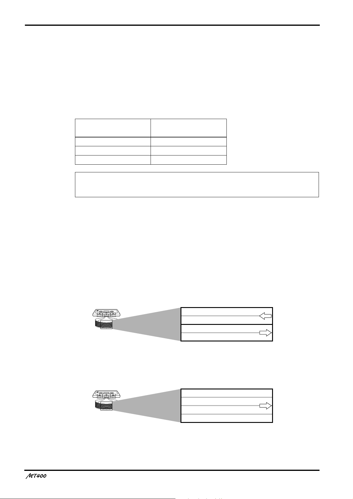
MT400 Recording Format
A normal cassette recorder uses only two tracks (i.e., left and right stereo channels) for each
side (A and B). The transport direction of the A side is opposite that of the B side. The MT400
uses only one side of the cassette, and records and plays up to four tracks simultaneously or
one at a time. Therefore, tapes with all four tracks recorded on the MT400 cannot be played
on normal cassette players. If you try to play back a tape recorded with normal cassette
recorders on the MT400, you will hear Tracks 3 and 4 play backwards.
Normal cassette recorder tracks
MT400 tracks
The tape speed of normal cassette recorders is 4.8 cm/second. On the other hand, the MT400
uses 9.5 cm/second as its standard speed to achieve high-quality sound.
—Owner’s Manual
Side B (left channel)
Side B (right channel)
Side A (right channel)
Side A (left channel)
Track 1
Track 2
Track 3
Track 4
transport
direction
transport
direction
transport
direction

5
About dbx Noise Reduction
The MT400 uses the dbx noise reduction system to reduce tape hiss and keep your recordings
clean and crisp. For the best performance, it is recommended that you use the dbx noise
reduction for all your recordings. You should always use the dbx noise reduction system to
correctly play back tapes that were recorded with the dbx system on.
Glossary
This section describes basic terminology used in this manual.
■
Input channel
A path (channel) for audio signal between a mixer input jack and the bus (see below). Signal
input at an input jack is adjusted for the volume level and tonal quality here before being sent
to the bus.
■
Track
The MT400 can record four individual sound sources simultaneously on the four sections of a
cassette tape. This does not mean that the tape is cut into four pieces. The tape forms four
magnetic bands along the length of the tape. Each magnetic recording band is called a “track”.
The MT400 can use up to four tracks (Tracks 1–4).
■
Bus
A path where multiple audio signals are mixed into one signal. The MT400 offers the
following buses that can be used depending on the purpose.
Stereo L/R bus — This bus is used to create a stereo signal. Stereo bus signal is output
from the STEREO OUT L/R jacks. You can record stereo L bus signal to both Track 1
and 3 of the recorder section, and stereo R bus signal to both Track 2 and 4. To monitor
stereo bus signals, use the MONITOR OUT L/R jacks. You can also monitor them via
headphones.
Cue bus — This bus is used to create a monaural signal for monitoring, which is
output from the MONITOR OUT L/R jacks. You can also monitor the signal via
headphones.
AUX 1 and 2 buses — These buses are used to send out signals to connected effects
processors from the AUX SEND 1 and 2 jacks in monaural. You can monitor the signals
via headphones.
■
Overdubbing
Overdubbing is a technique used to record new sounds to empty tracks while listening to the
sounds already recorded on other tracks.
■
Ping-pong recording
Ping-pong recording is a technique used to free up tracks by mixing one or two existing tracks
to an unused track.
■
Mixdown
Mixdown is a technique used to mix the sounds into a balanced stereo mix and record it to a
stereo master recorder. It is also called “tracking down”.
—Owner’s Manual
6
.
Touring the MT400
This section takes you on a tour of the MT400, identifying the various parts to familiarize you
with your new recorder.
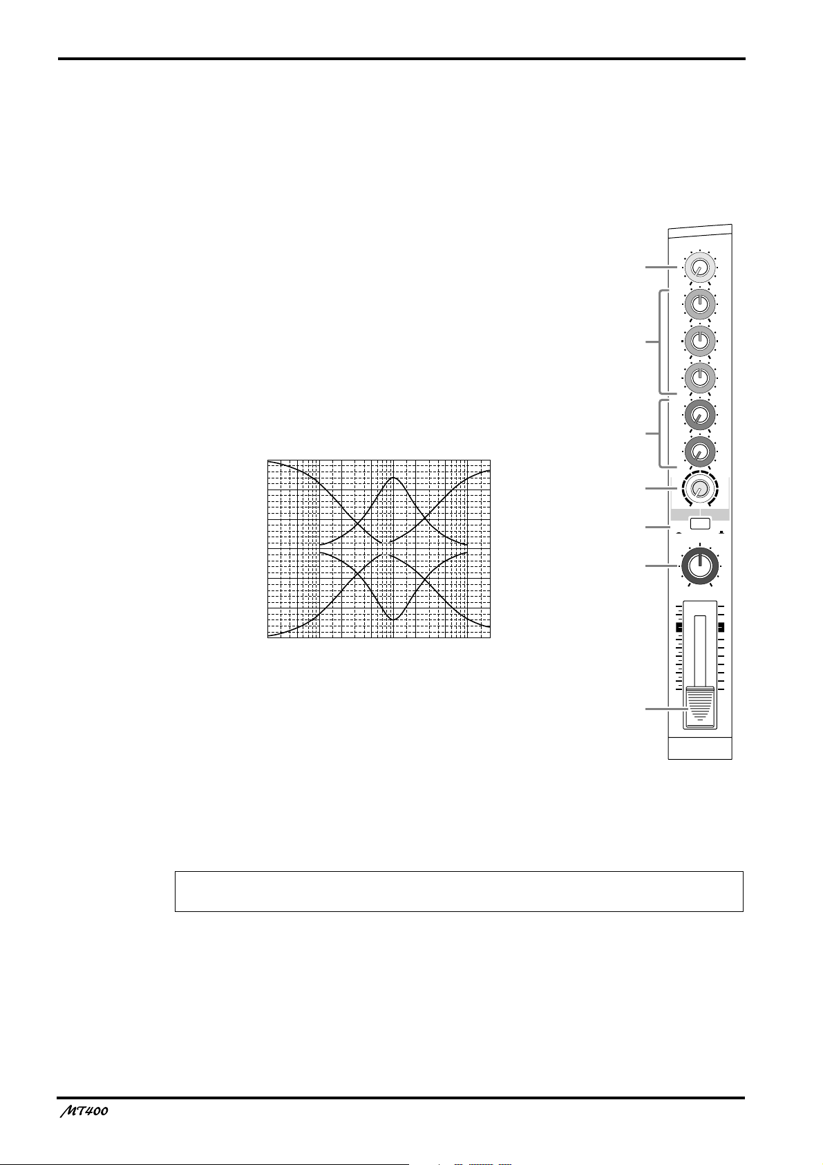
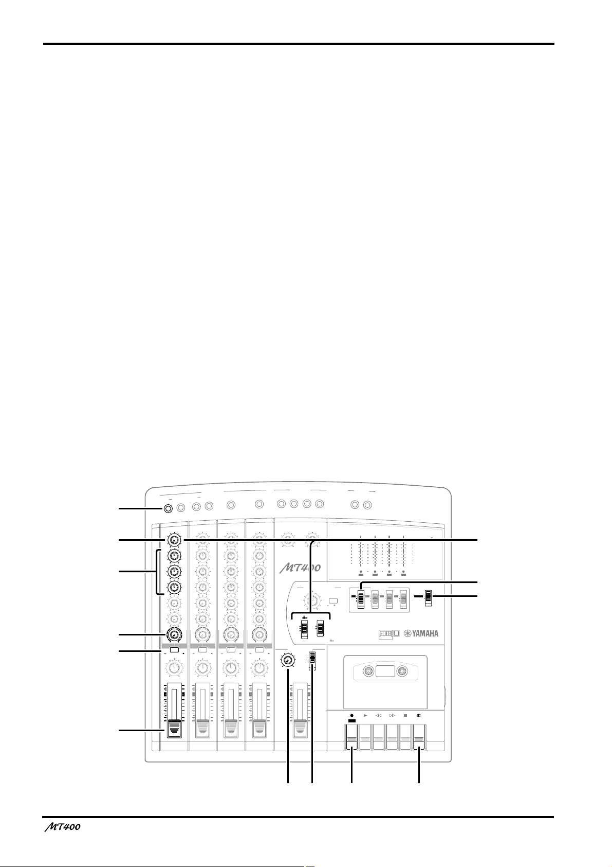
Input Channels
A
GAIN control
This rotary control adjusts the sensitivity of the MIC/LINE
INPUT jack
so that both microphone and line-level (such
d
as a synthesizer) signals can be handled with ease.
B
EQ control
These rotary controls are used to adjust a tonal quality of the
high, middle, and low frequency bands independently. They
boost (amplify) and cut (attenuate) the corresponding basic
frequency in the range of
±
12 dB. A flat setting (i.e., no boost
or cut) can be set quickly using the control’s center detentes.
15
10
5
0
–5
Response (dB)
–10
–15
50
Frequency (Hz)
10k 20k1k10020
5k2k500200
HIGH: Basic frequency 12 kHz (shelving type)
MID: Basic frequency 1 kHz (peaking type)
LOW: Basic frequency 80 Hz (shelving type)
1
2
3
4
5
6
7
GAIN
LINE MIC
HIGH
–12 +12
MID
–12 +12
LOW
–12 +12
AUX
1
010
AUX
2
010
MIX CUE
010
MIC/LINE
to L
TAPE
PAN
10
9
8
7
6
5
4
3
2
1
0
TAPE
MIC/
LINE
INPUT-FLIP
LR
1
C
AUX controls
These rotary controls are used to send the input channel (1–4) signal to the AUX SEND 1 and
2 outputs. They are commonly used to adjust the level of signal sent to external effects
processors.
Note: The AUX controls handle post-fader signals (signals that have passed through the
faders
7
). If the faders are lowered all the way, the AUX control settings will not be effective.
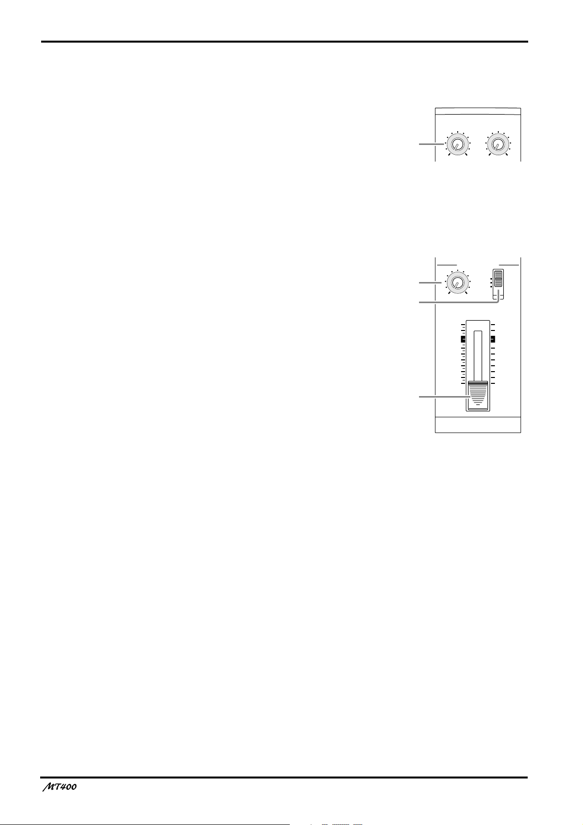
D
CUE control
This control is used to adjust the level of Track (1–4) input signal and playback signal that will
be sent to the cue bus. The CUE bus signals are output from the PHONES jack or the
MONITOR OUT jack for monitoring.The CUE signal source depends on the [INPUT-FLIP]
switch
—Owner’s Manual
5
INPUT-FLIP
TAPE
MIC/
LINE
GAIN
HIGH
LINE MIC
–12 +12
MID
–12 +12
LOW
–12 +12
MIX CUE
010
INPUT-FLIP
TAPE
MIC/
LINE
GAIN
HIGH
LINE MIC
–12 +12
MID
–12 +12
LOW
–12 +12
MIX CUE
010
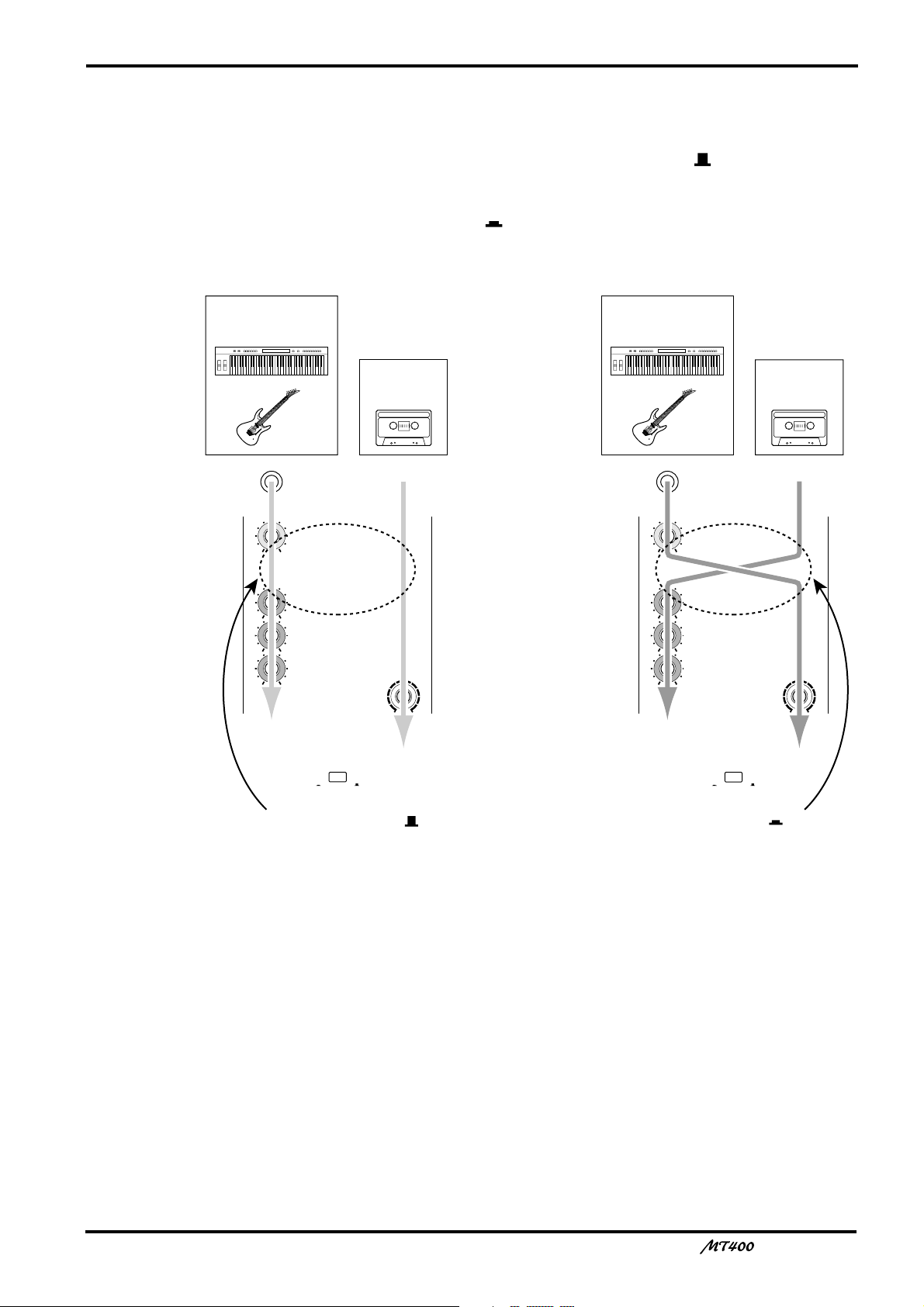
To CUE bus To ST bus
To ST bus
and tape
To ST bus
and tape
MT400 tape
signal
Musical instrument
signal input from
MIC/LINE INPUT jack
Musical instrument
signal input from
MIC/LINE INPUT jack
MT400 tape
signal
When INPUT-FLIP
switch is MIC/LINE ( )
When INPUT-FLIP
switch is TAPE ( )
E
INPUT-FLIP switch
This switch is used to select the destination of the signal input from the MIC/LINE INPUT
jacks and the tape signal. With the switch in the MIC/LINE position ( ), the MIC/LINE
input signal is fed to the ST bus via the input channel and the tape signal is fed to the CUE
bus.
With the switch in the TAPE position ( ), the MIC/LINE input 1, 3 (2, 4) signal is fed to the
ST L (ST R) bus and the tape signal is fed to the ST bus via the input channel.
7
F
PAN control
This rotary control is used to adjust the stereo position (left or right) of input channel signal
that will be sent to the Stereo bus. For recording via the Stereo bus (See page 22), turn this
control all the way to the left to assign the signal to odd tracks (1, 3), and all the way to the
right to assign the signal to even tracks (2, 4). For mixdown you can use it to pan the playback
signal in the stereo mix.
G
Fader
For recording ([INPUT-FLIP] switch: MIC/LINE), use the fader to adjust the level of the
input channel signal that is recorded to a track. For mixdown ([INPUT-FLIP] switch: TAPE),
use it to adjust the playback level of each track. Unity gain is obtained when the fader is
positioned about the 7–8 mark.
Unity gain : The condition where the output signal and input signal are at the same level,
with signal-to-noise ratio and distortion set to optimum.
—Owner’s Manual
8
Stereo Inputs
H
LEVEL controls
These rotary controls are used to adjust the level of the
stereo input signals that are input at the STEREO
INPUT jacks 5 and 6 or 7 and 8. These signals are
usually sent to the Stereo bus for mixing with Input
Channel 1–4 signals and tape signals.
Monitor/Master Section
I
MONITOR LEVEL control
This rotary control adjusts the level of the monitor
signal that is sent to the MONITOR OUT
PHONES
J
Monitor select switch
h
jacks.
This switch is used to select the signal source for the
MONITOR OUT
STEREO
... This position selects the Stereo bus and
m
and PHONES
allows you to monitor the STEREO
OUT signal.
ST+CUE
.... This position selects the Stereo bus and
the CUE bus as the monitor source.
CUE
........... This position selects the CUE bus as the
monitor source.
h
m
and
.
LEVEL
5L–6R
LEVEL
7L–8R
8
010
MONITOR/PHONES
STEREO
ST+CUE
CUE
9
010
LEVEL
MIN MAX
J
STEREO
10
9
8
7
6
5
4
3
2
1
0
K
K
STEREO fader
Use this fader to adjust the level of the stereo signal
that is sent to the STEREO OUT jacks. Unity gain is
obtained when the fader is positioned about the 7–8
mark.
Unity gain : See
7
Fader.
—Owner’s Manual
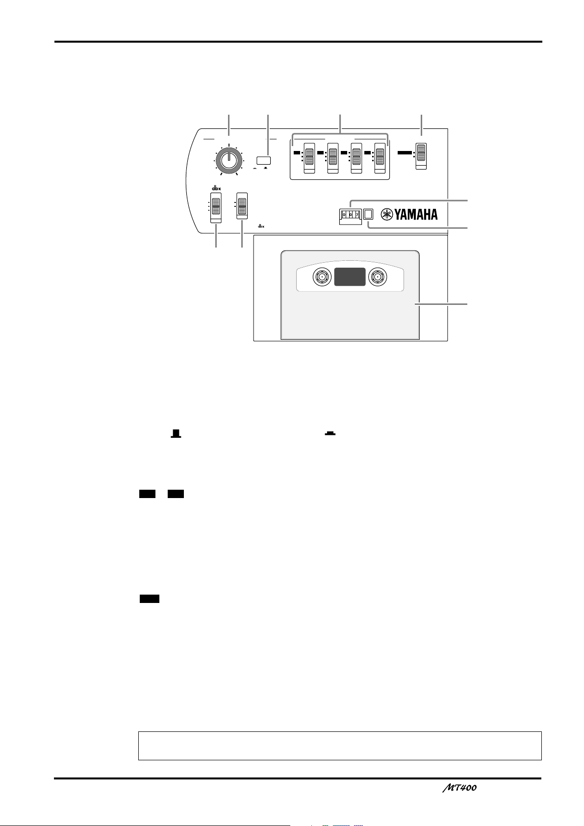
Recorder Section
4TR4
STEREO
METER SELECTREC SELECT
ZERO STOP
PITCH
NOISE REDUCTION SYSTEM
TAPE SPEED CONTROL
OFF
R
3
OFF
L
2
OFF
R
1
OFF
L
ON
OFF
ON
OFF
SYNC
4.8/ 9.5
– +
ONLM
QP
R
S
T
9
L
PITCH control
This rotary control adjusts the tape speed in the range of
M
Tape speed switch
This switch is used to select 4.8 cm/second or 9.5 cm/second for the tape speed. Set the switch
to 9.5 ( ) for normal recording, and 4.8 ( ) for playback of a tape recorded with a normal
cassette tape recorder.
N
REC SELECT switches
These switches are used to select recording sources for tracks.
1 4
OFF
L/R
O
METER SELECT switch
This switch selects the signal level to be displayed on the level meters
4TR
STEREO
P dbx switch
Use this switch to turn on and off the dbx noise reduction system.
ON...............The dbx noise reduction system is turned on for all tracks.
OFF.............The dbx noise reduction system is turned off for all tracks.
SYNC .........The dbx noise reduction system is turned off only for Track 4.
±
10%.
– ...Input channel (1–4) signals are routed directly to the corresponding tracks for
recording (direct recording).
.............The corresponding tracks are disabled for recording.
..............The corresponding tracks are ready for recording and receive L channel (Tracks 1
and 3) or R channel (Tracks 2 and 4) signals.
a
.
............The level meters display the track input signal levels during recording and the
track output signal levels during playback.
....The level meters display the Stereo bus signal levels (signal output from the
STEREO OUT jacks).
Note: The SYNC setting is used for a special application in which Track 4 is used for
synchronization. See page 41 for more information.
—Owner’s Manual
10
Q ZERO STOP switch
Use this switch to turn on and off the Zero Stop function. With this switch set to on (ON), the
tape rewind automatically stops when the tape counter returns to just before “000”.
R Tape counter
This 3-digit tape counter indicates the tape position.
S Counter reset button
This button resets the tape counter value to “000”.
T Cassette compartment
Insert a cassette tape here.
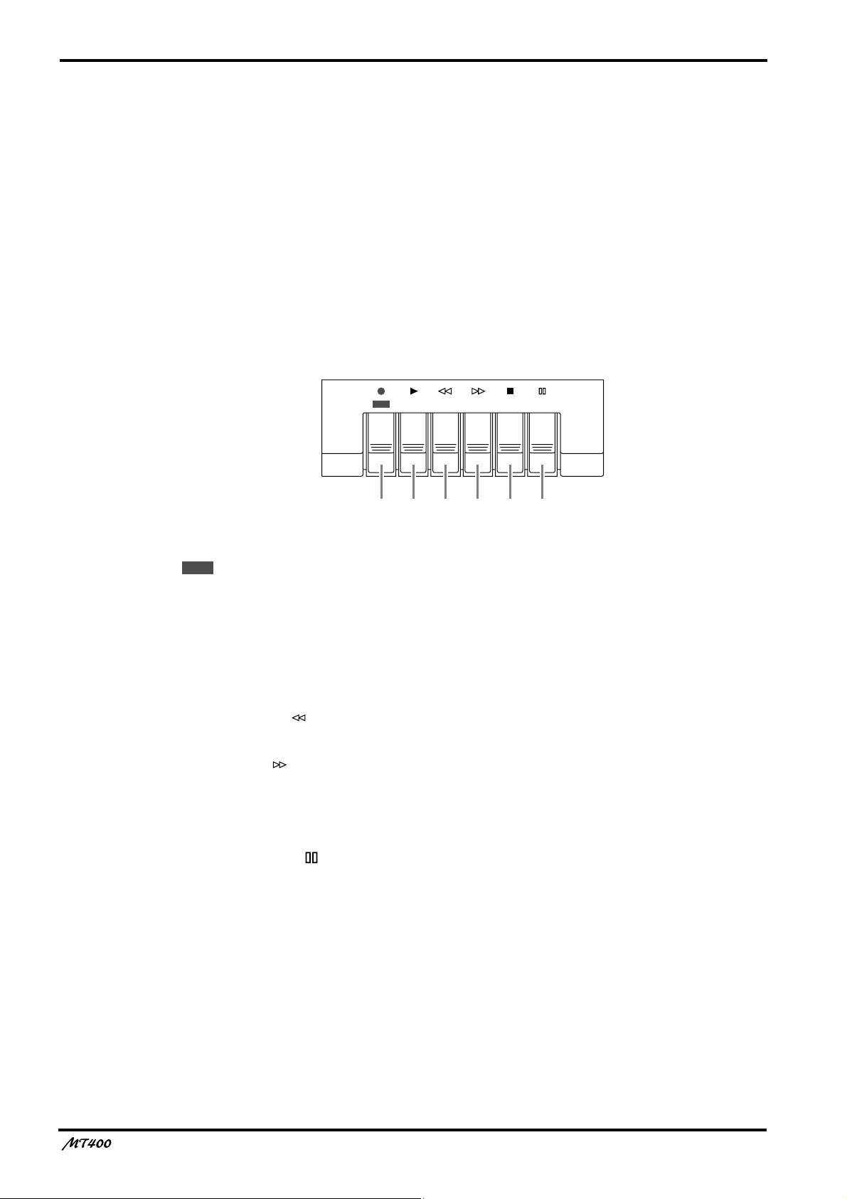
Transport Section
REC PLAY REW FF STOP PAUSE
UVWXYZ
REC
U button (
Pressing this button turns the PLAY button V on and starts recording on the currently
available tracks. When you press this button during playback, recording starts from the point
you press the button. This button is disabled if a tape is not set or write-protect tubs on the
tape are broken.
V PLAY button (
Use this button to start playback of the tracks.
●)
®®®®)
W REW button ( )
Use this button to rewind the tape.
X FF button ( )
Use this button to fast forward the tape.
Y STOP button (■)
Use this button to stop the tape transport.
Z PAUSE button ( )
Use this button to pause recording or playback. Pressing this button to stop recording or
playback and pressing it again will resume recording or playback.
—Owner’s Manual
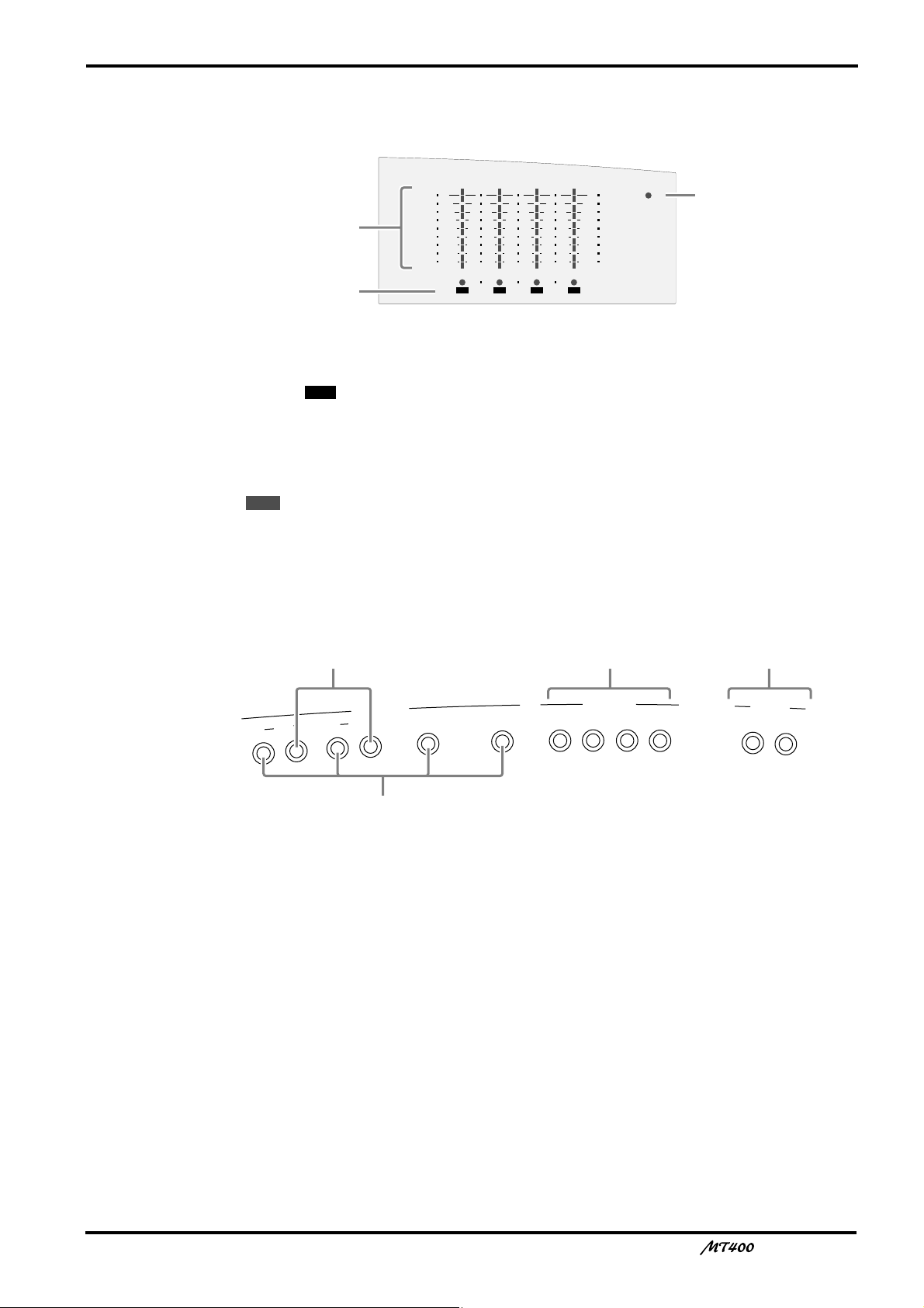
Meter Section
4
+6
+3
0
–5
–10
+6
+3
0
–5
–10
POWER
321
RL
REC
a
b
c
AU
X S
EN
D
STEREO INPUT
M
IC
/L
IN
E IN
P
U
T
IN
SE
R
T I/O
IN
S
ER
T I/O
1
2
1
2
3
4
5L 6R 8R7L
ge
d
f
a Level meters
These meters show the signal levels from –10 dB to +6 dB. When the METER SELECT switch
O is set to “ ”, they show the track signal levels during recording and playback. When the
METER SELECT switch is set to “STEREO”, they show the STEREO OUT signal levels.
b REC SELECT indicator
These indicators show which tracks are selected for recording. They flash when you select
recording sources by the REC SELECT switches
REC
the button to start recording.
4TR
N, and light up continuously when you press
11
c POWER indicator
This indicator lights up when you turn on the power to the unit.
Input/Output Section
d MIC/LINE INPUTs 1–4
Use these 1/4" TRS phone jacks to connect microphones and electronic musical instruments
such as a synthesizer to the MT400.
e INSERT I/O
Use these TRS phone jacks to output, then input channels 1 and 2 signals. Typically, signal
processors, such as compressors, limiters, and noise gates are connected to these jacks. Signals
output from the mixer section are processed on the effects processor and returned to the
mixer via these jacks. (See page 28)
f STEREO INPUTs
Use these 1/4" phone jacks to connect line-level sound sources that have stereo outputs, such
as a synthesizer and a CD player. They can also be used to return the processed stereo signals
from external effects processors, such as a reverb unit. (See page 29)
g AUX SEND
Use these 1/4" phone jacks to output the channel signals adjusted by the AUX controls 3. You
can use these as effect sends by connecting to the effects processors’ inputs. (See page 29)
—Owner’s Manual
12
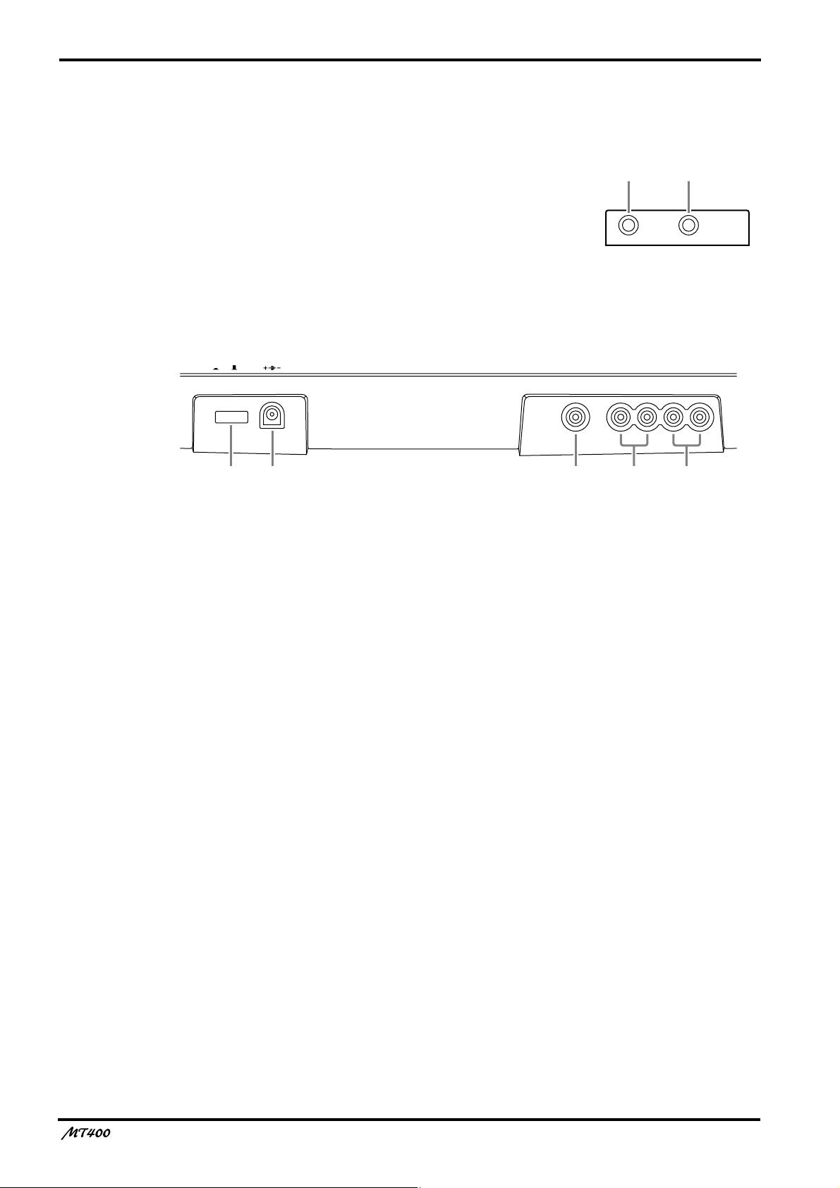
Front Panel
h PHONES
A pair of stereo headphones can be connected here for
monitoring. The headphone signal is the same as the
MONITOR OUT signal.
hi
i PUNCH I/O
An optional footswitch, such as the Yamaha FC5, can be
connected here for foot-controlled punch in/out.
Rear Panel
DC 12VPOWER
ON/ OFF
j POWER ON/OFF switch
Use this switch to turn on and off the MT400.
k DC 12V
Connect the AC adapter here.
Use a 12 V AC adapter of at least 650 mA.
PHONES PUNCH I/O
SYNC OUT MONITOR OUT STEREO OUT
lkj
RLRL
nm
l SYNC OUT
Use this phono jack to individually output FSK and SMPTE synchronization signals recorded
on the sync track (Track 4).
m MONITOR OUTs
Use these phono jacks to send the monitor signals. Connect your hi-fi system or powered
speakers.
n STEREO OUTs
Use these phono jacks to output Stereo bus signal adjusted by the STEREO fader. Connect
them to your master recorder’s stereo inputs for mixdown.
—Owner’s Manual
The First Session
4
4TR4
STEREO
+6
+3
0
–5
–10
+6
+3
0
–5
–10
POWER
AUX
SE
ND
STEREO INPUT
METER SELECTREC SELECT
MONITOR/PHONES
ZERO STOP
PITCH
NOISE REDUCTION SYSTEM
TAPE SPEED CONTROL
321
RL
REC
REC PLAY REW FF STOP PAUSE
OFF
R
3
OFF
L
2
OFF
R
1
OFF
L
ON
OFFONOFF
SYNC
STEREO
ST+CUE
CUE
MULTITRACK CASSETTE RECORDER
MIC/L
INE IN
P
U
T
INSERT
I/O
INSERT I/O
1
2
1
2
3
4
5L 6R 8R7L
4.8/ 9.5
– +
LEVEL
STEREO
7L–8R
010
LEVEL
5L–6R
010
LEVEL
MIN MAX
10
9
8
7
6
5
4
3
2
1
0
GAIN
HIGH
10
9
8
7
6
5
4
3
2
1
0
LINE MIC
–12 +12
MID
–12 +12
LOW
–12 +12
AUX
1
010
AUX
2
MIX CUE
MIX CUE MIX CUE MIX CUE
010
010
PAN
INPUT-FLIP
TAPE
TAPE
MIC/
LINE
MIC/LINE
to L
LR
1
GAIN
HIGH
10
9
8
7
6
5
4
3
2
1
0
LINE MIC
–12 +12
MID
–12 +12
LOW
–12 +12
AUX
1
010
AUX
2
010
010
PAN
INPUT-FLIP
TAPE
TAPE
MIC/
LINE
MIC/LINE
to R
LR
2
GAIN
HIGH
10
9
8
7
6
5
4
3
2
1
0
LINE MIC
–12 +12
MID
–12 +12
LOW
–12 +12
AUX
1
010
AUX
2
010
010
PAN
INPUT-FLIP
TAPE
TAPE
MIC/
LINE
MIC/LINE
to L
LR
3
GAIN
HIGH
10
9
8
7
6
5
4
3
2
1
0
LINE MIC
–12 +12
MID
–12 +12
LOW
–12 +12
AUX
1
010
AUX
2
010
010
PAN
INPUT-FLIP
TAPE
TAPE
MIC/
LINE
MIC/LINE
to R
LR
4
PHONES PUNCH I/O
SYNC OUT MONITOR OUT STEREO OUT
RLRL
DC 12VPOWER
ON/ OFF
YAMAHA YAMAHA
YAMAHA
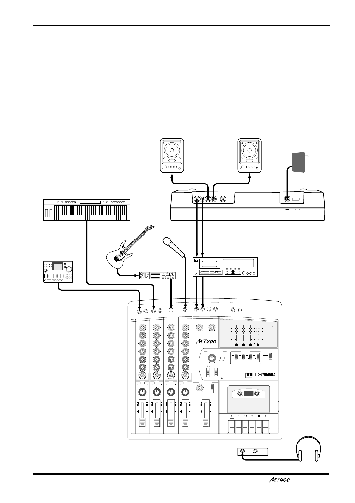
AC adapter
Master recorder
Powered speakers /
Hi-fi stereo system
Headphones
Rhythm machine
Microphone
Guitar
Keyboard
Guitar effects
processor
This chapter explains how to record four tracks individually and mix your first MT400 session
onto a master recorder.
Preparation
Quick-Start System
13
—Owner’s Manual
14
Turning On the MT400
1. Make sure that the plug of the supplied AC
adapter is securely connected to the DC12V
jack on the rear of the MT400.
2. Plug the other end of the AC adapter into a
suitable AC outlet.
3. Press the POWER switch on the rear panel of
the MT400. The POWER indicator in the
meter section lights up.
Loading a Cassette Tape
Before loading a cassette tape, make sure the tape is
not slack inside the cassette. Also, make sure the write-
Recording the First Track
The MT400 allows signals input at MIC/LINE INPUT 1–4 to be directly recorded on Tracks
1–4 respectively (this is called “direct recording”). Connecting a sound source to MIC/LINE
INPUT 1 will automatically select Track 1 for recording, and connecting another sound
source to MIC/LINE INPUT 3 will automatically select Track 3 for recording. This is
convenient for recording one sound source at a time.
This section explains how to record the first sound source in Track 1.
protect tabs are not broken. If they are broken, you
cannot record on the tape.
1. Open the cassette compartment cover.
2. Load the cassette into the compartment with
the A side facing up.
3. Close the cassette compartment cover.
If it is a new tape, fast forward and rewind it once to
prevent binding, which may occur due to the tape
being tightly wound during manufacturing.
4. Press the [PLAY] button to start playback, and
stop after about 20 seconds.
It is best not to use the first and last 20 seconds of a
tape, as the splice between the leader and tape can
cause distortion.
Preparation Before Recording
UT
P
E IN
/LIN
1
7
C
A
2
8
MIC
INSERT I/O
2
INSERT I/O
1
1
GAIN
GAIN
LINE MIC
LINE MIC
HIGH
HIGH
–12 +12
MID
LOW
AUX
1
AUX
2
MIX CUE
PAN
10
9
8
7
6
5
4
3
2
1
0
–12 +12
MID
–12 +12
–12 +12
LOW
–12 +12
–12 +12
AUX
1
010
010
AUX
2
010
010
MIX CUE MIX CUE MIX CUE
010
010
TAPE
MIC/LINE
MIC/LINE
to L
to R
MIC/
TAPE
TAPE
LINE
INPUT-FLIP
INPUT-FLIP
PAN
LR
LR
10
9
8
7
6
5
4
3
2
1
0
2
TAPE
MIC/
LINE
GAIN
LINE MIC
HIGH
–12 +12
MID
–12 +12
LOW
–12 +12
AUX
1
010
AUX
2
010
010
MIC/LINE
to L
TAPE
INPUT-FLIP
PAN
LR
10
9
8
7
6
5
4
3
2
1
0
4
3
3
GAIN
LINE MIC
HIGH
–12 +12
MID
–12 +12
LOW
–12 +12
AUX
1
010
AUX
2
010
010
TAPE
MIC/LINE
to R
MIC/
TAPE
LINE
INPUT-FLIP
PAN
LR
10
9
8
7
6
5
4
3
2
1
0
4
TAPE
MIC/
LINE
5L 6R 8R7L
LEVEL
LEVEL
MIN MAX
STEREO INPUT
5L–6R
7L–8R
LEVEL
010
010
MULTITRACK CASSETTE RECORDER
TAPE SPEED CONTROL
PITCH
– +
SYNC
MONITOR/PHONES
STEREO
ST+CUE
CUE
STEREO
10
9
8
7
6
5
4
3
2
1
0
ZERO STOP
ON
OFFONOFF
4.8/ 9.5
NOISE REDUCTION SYSTEM
AUX SEND
1
+6
+3
0
–5
–10
REC
L
PLAY REW FF STOP
REC
2
+6
POWER
+3
0
–5
–10
4321
RL
METER SELECTREC SELECT
431 4TR2
STEREO
OFFROFFLOFFROFF
PAUSE
9
3
4
—Owner’s Manual
B 0
6
5

15
Selecting a recording track
1 Connect a sound source to MIC/LINE INPUT
1.
It is best to record a rhythm instrument, such as a
rhythm machine, drums, or a rhythm guitar, first.
2 Set the [INPUT-FLIP] switch on Input Channel
1 to “MIC/LINE ( )”.
This switch setting sends the MIC/LINE INPUT signal
to the corresponding input channel.
3 Set Track 1 [REC SELECT] switch to “ ”.
The [REC SELECT] switches enable you to select a
recording source for each track. With Track 1 [REC
SELECT] switch set to “ ”, Track 1 is ready for
recording, and the signal on Input Channel 1 is sent to
Track 1. Also, the Track 1 REC SELECT indicator
flashes.
1
1
Checking the recording level
It is essential to set an appropriate recording level to
achieve the best sound quality. Be sure to adjust the
recording level before each recording session.
4 Set the [METER SELECT] switch to “ ”.
The [METER SELECT] switch is used to select a signal
monitored on the level meters. With the “ ”
setting, you can monitor the input level of the
recording source on the recording/recording-pause
tracks, and the tape signal level on the playback tracks.
4TR
4TR
Monitoring a track recording signal
0 Set the monitor select switch to “CUE”.
The monitor select switch enables you to select a
monitoring source. The “CUE” setting sends the CUE
bus signal (monaural) to the connected audio system
or headphones for monitoring via the PHONES and
MONITOR OUT jacks.
A Set the CUE control on Input Channel 1
midway around noon.
The CUE controls on Input Channels 1–4 adjust the
level of the signals (recording source signals on the
recording/recording-pause tracks, and tape signals on
the playback tracks) that are sent from Tracks 1–4 to
the CUE bus.
B While monitoring the signal through the
headphones or the audio system, use the
MONITOR LEVEL control to adjust the
monitoring sound to the desired level.
C If necessary, use the EQ controls to adjust
tonal quality.
Adjusting the EQ controls will change the recording
level as well. After you adjust the EQ controls, adjust
the GAIN control for the recording level again, if
necessary.
5 Press the [PAUSE] button.
6 Press the button.
The Track 1 REC SELECT indicator stops flashing and
lights up continuously, and the MT400 enters
recording pause mode. Since you pressed the [PAUSE]
button, recording does not start.
REC
7 Turn the GAIN control on Input Channel 1 all
the way to LINE.
8 Raise the fader on Input Channel 1 up to
between marks 7 and 8.
9 Play the sound source, and turn the GAIN
control while checking the level meter to
adjust the recording level. Set the [dbx]
switch and the [ZERO STOP] switch to “ON”.
Adjust the GAIN control so that the +3 segment of the
level meter lights up momentarily on the loudest
sounds if dbx has been turned off, and the +6 segment
of the level meter lights up momentarily if dbx has
been turned on.
If the recording level is very high even when the GAIN
control is turned all the way to LINE, lower the output
level on the sound source.
—Owner’s Manual
 Loading...