

Yamaha Audio DVD-S1200 (Europe) User Manual
NATURALSOUND DVD AUDIO / VIDEO PLAYERDVD-S1200
STANDBY
PHONES
LEVEL
STANDBY
/ON
010
VIDEO OFF
AUDIO/VIDEO
GB
GROUP
AUDIO
PO
/
VIDEO
WER
Í
/I
1 2
567
9
0
SET U
P
VIDE
O
O
F
F
GROU
P
T
O
P M
E
N
U
O
N
S
C
R
EE
E
N
N
T
E
PL
R
E
P
E
SKIP
D
VD
V
7562
60
R
A
Y M
O
D
E
SU
B
T
IT
L
E
A
UDIO ANG
A
T
A
-
B
H
P
-V
.S
.S
.
S
P
-V
.S
.S
SLOW
/
SEARCH
STO
P
PA
USE
PLA
Y
OPEN/CLOSE
34
8
CA
S
N
10
C
E
L
M
A
R
K
E
R
PAGE
MEN
U
R
ET
U
R
N
LE
.
Before connecting, operating or adjusting this product, please read these instructions completely.
Please keep this manual for future reference.
DVD AUDIO/VIDEO PLAYER
Owners manual
AUDIO/VIDEO
Dear customer
Thank you for purchasing this product.
For optimum performance and safety, please read these instructions
carefully.
Operations in these instructions are described mainly
with the remote control, but you can do the operations on
the main unit if the controls are the same.
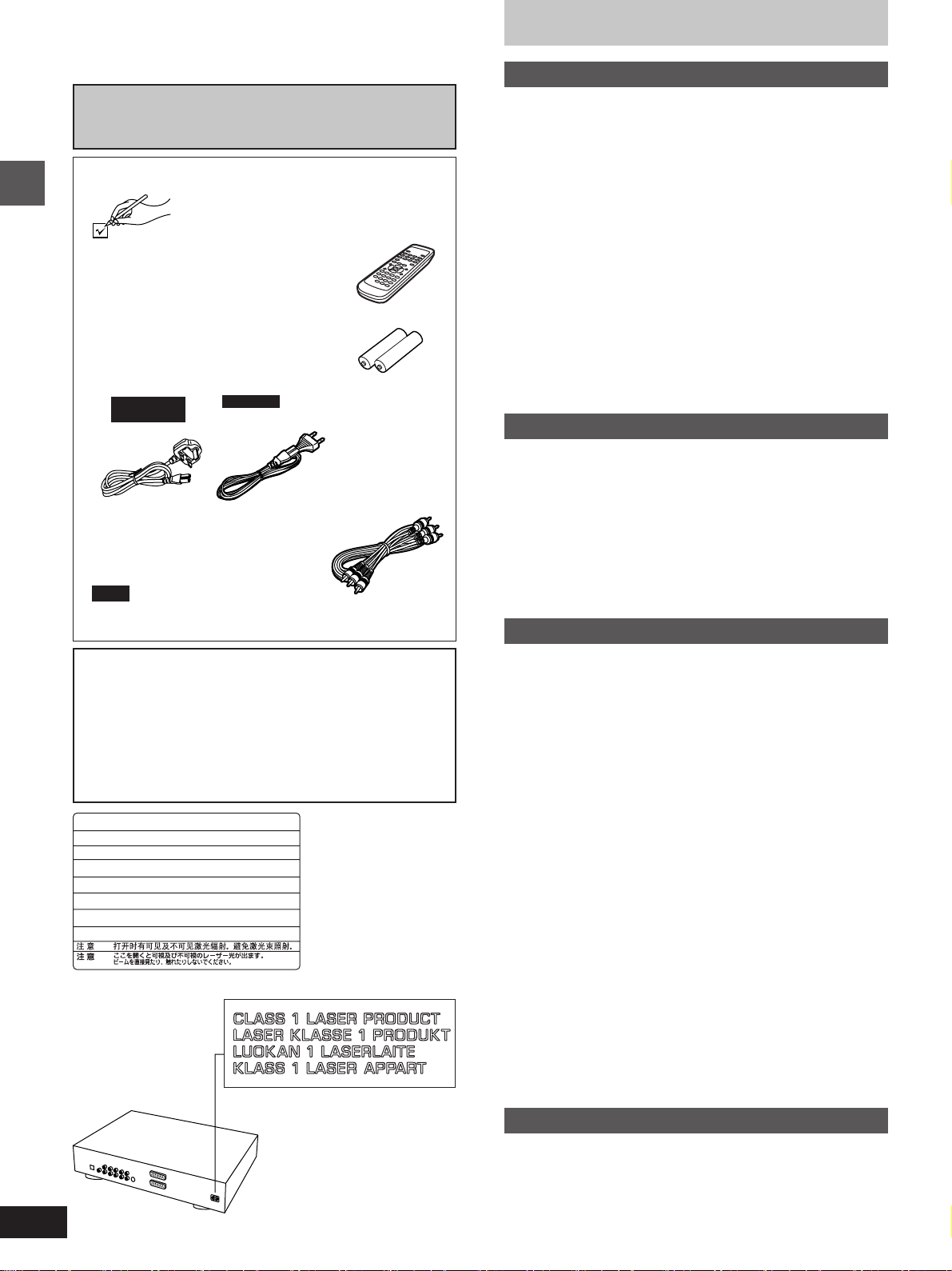
Accessories
Please check and identify the supplied
accessories.
¸ Remote control . . . . . . . . . . . . . . 1
Getting started
¸ Batteries . . . . . . . . . . . . . . . . . . . . 2
for remote control
¸ AC mains lead . . . . . . . . . . . . . . . 1
For the United
Kingdom
¸ Audio/video cable . . . . . . . . . . . . 1
Note
The included AC mains lead is for use with this unit only. Be
sure to use the included AC power supply cord with this unit.
CAUTION!
THIS PRODUCT UTILIZES A LASER.
USE OF CONTROLS OR ADJUSTMENTS OR PERFORMANCE OF PROCEDURES OTHER THAN THOSE SPECIFIED HEREIN MAY RESULT IN HAZARDOUS RADIATION
EXPOSURE.
DO NOT OPEN COVERS AND DO NOT REPAIR
YOURSELF. REFER SERVICING TO QUALIFIED
PERSONNEL.
-
VISIBLE AND INVISIBLE LASER RADIATION WHEN OPEN.
DANGER
AVOID DIRECT EXPOSURE TO BEAM.
-
VISIBLE AND INVISIBLE LASER RADIATION WHEN OPEN.
CAUTION
AVOID EXPOSURE TO BEAM.
-
RAY ONNEMENT LASER VISIBLE ET INVISIBLE EN CAS D’OUVERTURE.
ATTENTION
EXPOSITION DANGEREUSE AU FAISCEAU.
-
SYNLIG OG USYNLIG LASERSTRÅLING VED ÅBNING.
ADVARSEL
UNDGÅ UDSÆTTELSE FOR STRÅLING.
-
AVATTAESSA OLET ALTTIINA NÄKYVÄÄ JA NÄKYMÄTÖN
VARO !
LASERSÄTEILYLLE. ÄLÄ KATSO SÄTEESEEN.
-
SYNLIG OCH OSYNLIG LASERSTRÅLNING NÄR DENNA DEL
VARNING
ÄR ÖPPNAD. BETRAKT A EJ STRÅLEN.
-
SYNLIG OG USYNLIG LASERSTRÅLING NÅR DEKSEL ÅPNES.
ADVARSEL
UNNGÅ EKSPONERING FOR STRÅLEN.
-
SICHTBARE UND UNSICHTBARE LASERSTRAHLUNG, WENN ABDECKUNG
VORSICHT
GEÖFFNET. NICHT DEM STRAHL AUSSETZEN.
-
-
For others
(FDA 21 CFR)
(IEC60825-1)
RQLS0233
(Inside of unit)
Table of contents
Getting started
Accessories . . . . . . . . . . . . . . . . . . . . . . . . . . . . . 02
Caution for AC Mains Lead. . . . . . . . . . . . . . . . .
Safety precautions . . . . . . . . . . . . . . . . . . . . . . .
The remote control . . . . . . . . . . . . . . . . . . . . . . .
Disc information . . . . . . . . . . . . . . . . . . . . . . . . .
Connection. . . . . . . . . . . . . . . . . . . . . . . . . . . . . .
Connecting an AV amplifier with a built-in decoder. . . . . . . . . .
Connection to digital audio equipment without a
decoder . . . . . . . . . . . . . . . . . . . . . . . . . . . . . . . . . . . . . . . . .
Connecting an AV amplifier with 5.1-channel audio input
terminals . . . . . . . . . . . . . . . . . . . . . . . . . . . . . . . . . . . . . . . .
Analog connection to a 2-channel amplifier or system
component . . . . . . . . . . . . . . . . . . . . . . . . . . . . . . . . . . . . . . .
Connections using the S video terminal . . . . . . . . . . . . . . . . . .
Connecting to a television and a video cassette recorder
with 21-pin SCART terminal . . . . . . . . . . . . . . . . . . . . . . . . .
Recording to MDs or cassette tapes. . . . . . . . . . . . . . . . . . . . .
Control reference guide . . . . . . . . . . . . . . . . . . . 10
Basic operations
Basic play . . . . . . . . . . . . . . . . . . . . . . . . . . . . . . 11
Resume function . . . . . . . . . . . . . . . . . . . . . . . . . . . . . . . . . . . . 12
Starting play from a selected title or track. . . . . . . . . . . . . . . . . 12
Skipping chapters or tracks. . . . . . . . . . . . . . . . . . . . . . . . . . . . 13
Frame-by-frame viewing . . . . . . . . . . . . . . . . . . . . . . . . . . . . . . 13
Fast forward and rewind–SEARCH . . . . . . . . . . . . . . . . . . . . . 13
Slow-motion play. . . . . . . . . . . . . . . . . . . . . . . . . . . . . . . . . . . . 13
Selecting still pictures–Page Skip . . . . . . . . . . . . . . . . . . . . . . . 14
Selecting groups to play . . . . . . . . . . . . . . . . . . . . . . . . . . . . . . 14
To enjoy even higher quality sound–VIDEO OFF . . . . . . . . . . 14
Advanced operations
Marking places to play again–MARKER . . . . . . 15
Changing soundtracks, subtitle languages and
angles . . . . . . . . . . . . . . . . . . . . . . . . . . . . . . . . 15
Changing the play sequence . . . . . . . . . . . . . . . 16
Program play . . . . . . . . . . . . . . . . . . . . . . . . . . . . . . . . . . . . . . . 16
All group play/Random play . . . . . . . . . . . . . . . . . . . . . . . . . . . 17
Repeat play . . . . . . . . . . . . . . . . . . . . . . . . . . . . . 18
Repeat play . . . . . . . . . . . . . . . . . . . . . . . . . . . . . . . . . . . . . . . . 18
A-B repeat play . . . . . . . . . . . . . . . . . . . . . . . . . . . . . . . . . . . . . 18
Increasing your enjoyment of movies and
music . . . . . . . . . . . . . . . . . . . . . . . . . . . . . . . . . 19
Enjoying virtual surround effects with 2 speakers or
headphones (VIRTUAL SURROUND (V.S.S.)). . . . . . . . . . . 19
Using headphones . . . . . . . . . . . . . . . . . . . . . . . 19
Using GUI screens . . . . . . . . . . . . . . . . . . . . . . . 20
Common procedures. . . . . . . . . . . . . . . . . . . . . . . . . . . . . . . . . 20
Screen for disc information . . . . . . . . . . . . . . . . . . . . . . . . . . . . 21
Shuttle screen . . . . . . . . . . . . . . . . . . . . . . . . . . . . . . . . . . . . . . 21
Screen for unit information . . . . . . . . . . . . . . . . . . . . . . . . . . . . 22
Changing settings . . . . . . . . . . . . . . . . . . . . . . . . 23
Common procedures. . . . . . . . . . . . . . . . . . . . . . . . . . . . . . . . . 23
Summary of settings . . . . . . . . . . . . . . . . . . . . . . . . . . . . . . . . . 24
Television settings. . . . . . . . . . . . . . . . . . . . . . . . . . . . . . . . . . . 26
Speaker setting . . . . . . . . . . . . . . . . . . . . . . . . . . . . . . . . . . . . . 27
Digital output . . . . . . . . . . . . . . . . . . . . . . . . . . . . . . . . . . . . . . . 28
Entering a password . . . . . . . . . . . . . . . . . . . . . . . . . . . . . . . . . 28
03
04
04
05
06
07
07
08
08
09
09
09
(Back of unit)
2
Reference
Glossary . . . . . . . . . . . . . . . . . . . . . . . . . . . . . . . . 29
Disc handling. . . . . . . . . . . . . . . . . . . . . . . . . . . . 29
Troubleshooting guide . . . . . . . . . . . . . . . . . . . . 30
Maintenance. . . . . . . . . . . . . . . . . . . . . . . . . . . . . 31
Specifications . . . . . . . . . . . . . . . . . . . . Back cover
Caution for AC Mains Lead
(For United Kingdom)
(U.K. model only)
For your safety, please read the following text
carefully.
This appliance is supplied with a moulded three pin
mains plug for your safety and convenience.
A 5-ampere fuse is fitted in this plug.
Should the fuse need to be replaced please ensure
that the replacement fuse has a rating of 5-ampere and
that it is approved by ASTA or BSI to BS1362.
Check for the ASTA mark m or the BSI mark o on the
body of the fuse.
If the plug contains a removable fuse cover you must
ensure that it is refitted when the fuse is replaced.
If you lose the fuse cover the plug must not be used
until a replacement cover is obtained.
A replacement fuse cover can be purchased from your
local dealer.
CAUTION!
IF THE FITTED MOULDED PLUG IS UNSUITABLE FOR THE SOCKET OUTLET IN YOUR
HOME THEN THE FUSE SHOULD BE REMOVED AND THE PLUG CUT OFF AND DISPOSED OF SAFELY.
THERE IS A DANGER OF SEVERE ELECTRICAL SHOCK IF THE CUT OFF PLUG IS INSERTED INTO ANY 13-AMPERE SOCKET.
WARNING: DO NOT CONNECT EITHER WIRE TO
THE EARTH TERMINAL WHICH IS MARKED WITH
THE LETTER E, BY THE EARTH SYMBOL n OR
COLOURED GREEN OR GREEN/YELLOW.
THIS PLUG IS NOT WATERPROOF—KEEP DRY.
Before use
Remove the connector cover.
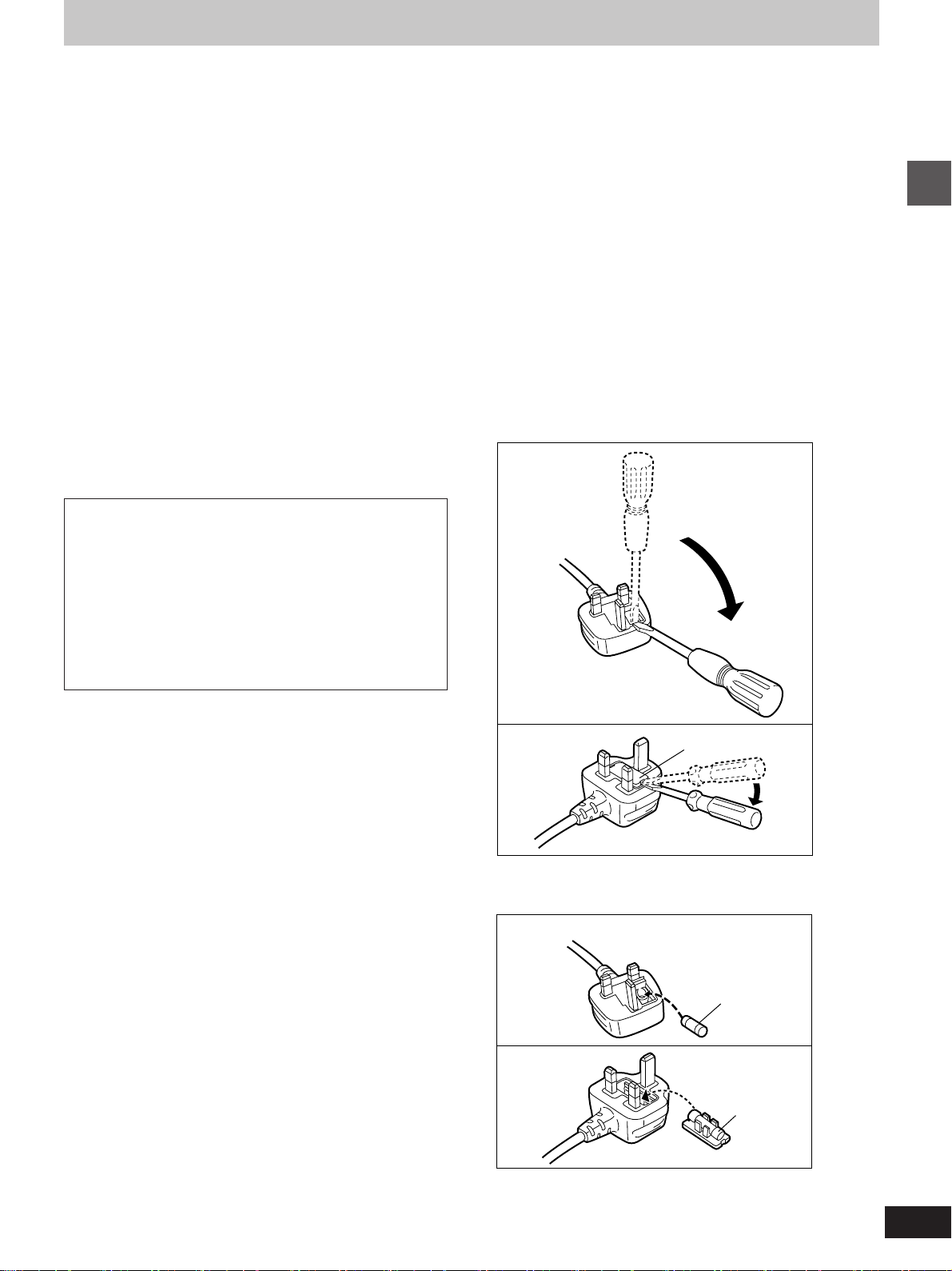
How to replace the fuse
The location of the fuse differ according to the type of
AC mains plug (figures A and B). Confirm the AC
mains plug fitted and follow the instructions below.
Illustrations may differ from actual AC mains plug.
1. Open the fuse cover with a screwdriver.
Figure A
Getting started
If a new plug is to be fitted please observe the wiring
code as stated below.
If in any doubt please consult a qualified electrician.
IMPORTANT
The wires in this mains lead are coloured in accordance with the following code:
Blue: Neutral, Brown: Live.
As these colours may not correspond with the coloured
markings identifying the terminals in your plug, proceed as follows:
The wire which is coloured Blue must be connected to
the terminal which is marked with the letter N or coloured Black or Blue.
The wire which is coloured Brown must be connected
to the terminal which is marked with the letter L or coloured Brown or Red.
Figure B
2. Replace the fuse and close or attach the fuse
cover.
Figure A
Figure B
Fuse cover
Fuse
(5 ampere)
Fuse
(5 ampere)
3
Safety precautions
The remote control
Placement
Set the unit up on an even surface away from direct sunlight, high
temperatures, high humidity, and excessive vibration. These conditions can damage the cabinet and other components, thereby shortening the unit’s service life.
Do not place heavy items on the unit.
Voltage
Do not use high voltage power sources. This can overload the unit
and cause a fire.
Do not use a DC power source. Check the source carefully when
setting the unit up on a ship or other place where DC is used.
Getting started
AC mains lead protection
Ensure the AC mains lead is connected correctly and not damaged. Poor connection and lead damage can cause fire or electric
shock. Do not pull, bend, or place heavy items on the lead.
Grasp the plug firmly when unplugging the lead. Pulling the AC
mains lead can cause electric shock.
Do not handle the plug with wet hands. This can cause electric
shock.
Foreign matter
Do not let metal objects fall inside the unit. This can cause electric
shock or malfunction.
Do not let liquids get into the unit. This can cause electric shock or
malfunction. If this occurs, immediately disconnect the unit from the
power supply and contact your dealer.
Do not spray insecticides onto or into the unit. They contain flammable gases which can ignite if sprayed into the unit.
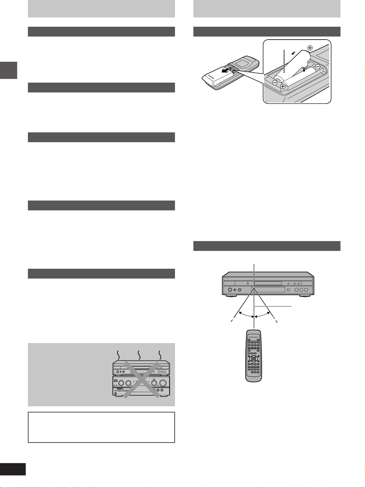
Batteries
R6, AA
1
2
³Insert so the poles (i and j) match those in the remote control.
³Do not use rechargeable type batteries.
Do not;
³mix old and new batteries.
³use different types at the same time.
³heat or expose to flame.
³take apart or short circuit.
³attempt to recharge alkaline or manganese batteries.
³use batteries if the covering has been peeled off.
Mishandling of batteries can cause electrolyte leakage which can
damage items the fluid contacts and may cause a fire.
If electrolyte leaks from the batteries, consult your dealer.
Wash thoroughly with water if electrolyte comes in contact with any
part of your body.
Remove if the remote control is not going to be used for a long period
of time. Store in a cool, dark place.
Replace if the unit does not respond to the remote control even when
held close to the front panel.
Use
Remote control signal sensor
Service
Do not attempt to repair this unit by yourself. If sound is interrupted,
indicators fail to light, smoke appears, or any other problem that is not
covered in these instructions occurs, disconnect the AC mains lead
and contact your dealer or an authorized service center. Electric
shock or damage to the unit can occur if the unit is repaired, disassembled or reconstructed by unqualified persons.
Extend operating life by disconnecting the unit from the power
source if it is not to be used for a long time.
Do not place the unit
on amplifiers or equipment that may become
hot.
The heat can damage the unit.
WARNING:
TO REDUCE THE RISK OF FIRE, ELECTRIC SHOCK OR
PRODUCT DAMAGE, DO NOT EXPOSE THIS APPLIANCE
TO RAIN, SPLASHING, DRIPPING OR MOISTURE.
7 m
30°30°
Aim at the sensor, avoiding obstacles, at a maximum range of 7 m
directly in front of the unit.
³Keep the transmission window and the unit’s sensor free from dust.
³Operation can be affected by strong light sources, such as direct
sunlight, and the glass doors on cabinets.
Do not;
³put heavy objects on the remote control.
³take the remote control apart.
³spill liquids onto the remote control.
4
A
a
Disc information
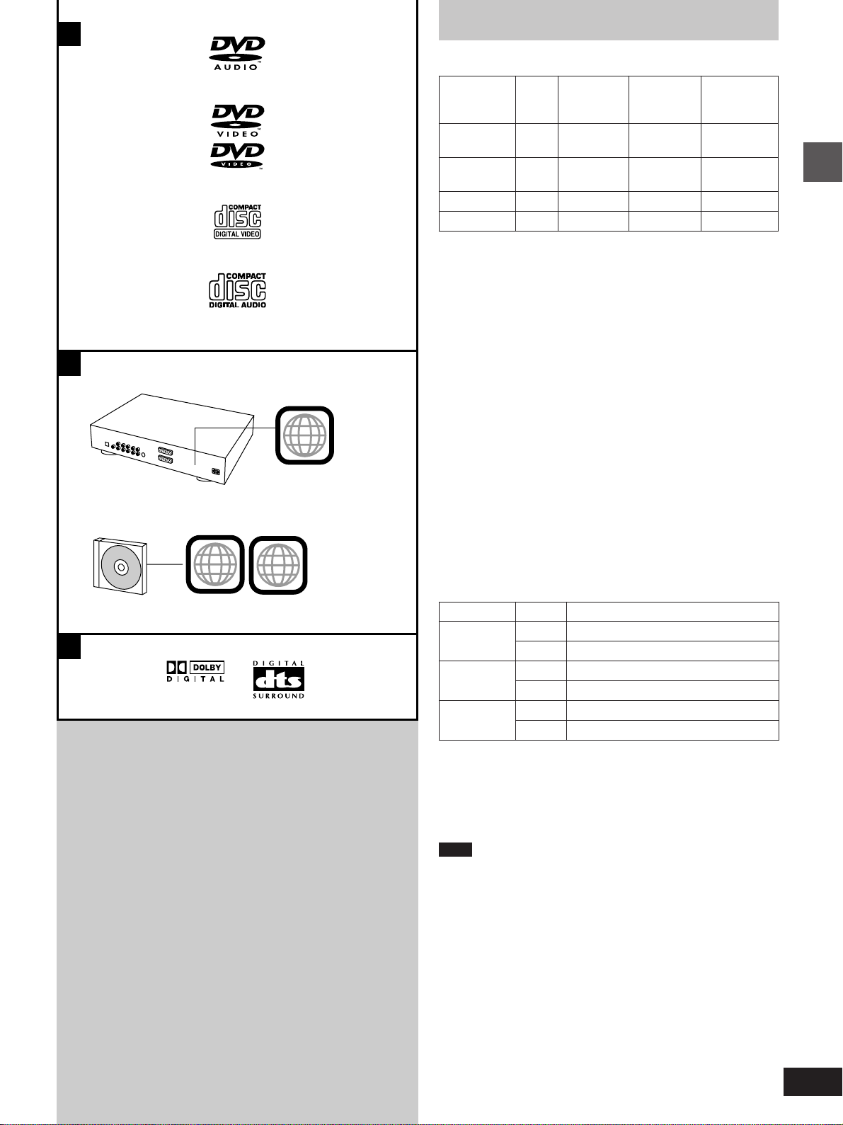
º Discs that can be played [A]
B
b
c
d
2
ALL
2
Region
Disc type
DVD-
¤
Audio
DVD-
¤
Video
Video CD
Audio CD
¤
See the table below for details on how video appears when playing
DVD-Video, Video CD and DVD-Audio. You can still enjoy the audio
on DVD-Audio irrespective of any differences in video systems.
Some DVD-R and DVD-RW can be played.
Logo
number
=
>
¤
?
@
–
See below
–
–
Video
system
PAL/NTSC
PAL/NTSC
PAL/NTSC
–
Indication
used in
instructions
[DVD-A]
[DVD-V]
[VCD]
[CD]
º Region Management Information (DVD-Video
only) [B]
Region numbers are allocated to DVD players and software according to where they are sold.
The region number of this unit is “2”.
DVD-Video can be played on this unit if their region number is the
same or includes the same number, or if the DVD is marked “ALL”.
Confirm the region number for this unit before choosing discs. The
number for this unit is indicated on the rear panel of the unit.
º Discs that cannot be played
DVD-ROM, DVD-R/DVD-RAM, CD-ROM, VSD, CDV, CD-G, +RW,
DVD-RW, CVD, SVCD, SACD, Divx Video Discs and Photo CD.
º DVDs that can be played [C]
This unit has a Dolby Digital decoder and a DTS decoder so you can
play DVDs with these marks.
º Type of disc for the type of connected TV
DVDs and Video CDs are recorded using either PAL or NTSC.
Refer to this table when selecting discs.
Getting started
C
TV type
Multi-
system TV
NTSC TV
PAL TV
¤1
If you select “NTSC” in “NTSC Disc Output” (á page 24), the
picture may be clearer.
¤2
The factory preset for “NTSC Disc Output” is “PAL60”, so no
changes to the settings are necessary.
(If your television is not equipped to handle PAL 525/60 signals the
picture will not be shown correctly.)
Note
When a disc which does not comply with Video CD standard is
played, the bottom part of the picture may disappear.
Disc
PAL
NTSC
PAL
NTSC
PAL
NTSC
TV Monitor
Y
¤1
Y
t
t
Y
¤2
Y
º Playing DVDs and Video CDs
The producer of the material can control how these discs are played.
This means that you may not be able to control play of a disc with
some operations described in these operating instructions. Read the
disc’s instructions carefully.
5
Connection
As this unit has built-in Dolby Digital and DTS decoders (á page 29), you can enjoy discs recorded with these systems by connecting this unit to the
6-channel input terminals on an AV amplifier (connection [B] below). However, to enjoy the special sound effects available with AV amplifiers that
can make you feel like you were in a cinema or hall, connect this unit digitally to the AV amplifier (connection [A] below).
Use analog connection [B] to enjoy the high quality audio (sampling frequencies of 192 kHz and 96 kHz) and multi-channel audio found
on DVD-Audio. If the disc is copyright-protected, the audio can only be output through the digital output terminal if it is converted to
48 kHz.
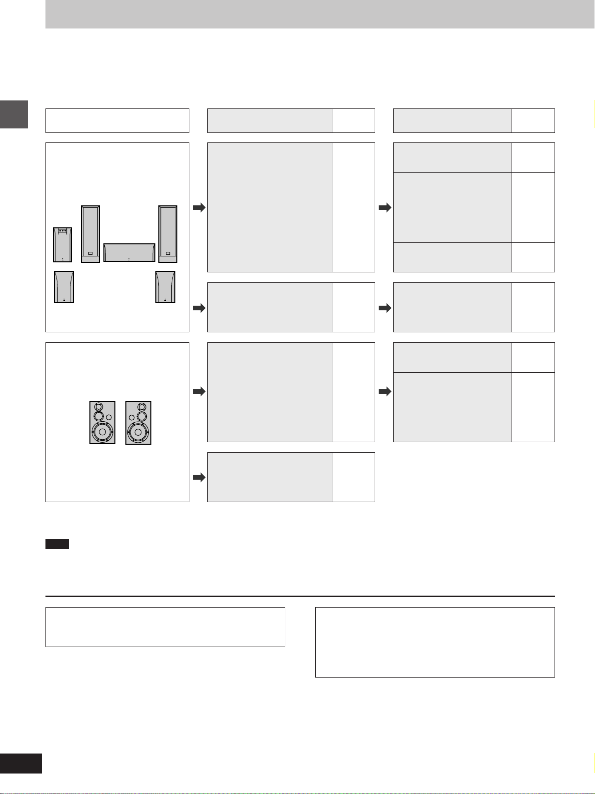
What you want to do
To enjoy 5.1-channel surround
sound
Getting started
To enjoy stereo
How to do it
[Digital\connection]
Connect to an amplifier with a
built-in decoder or a separate
decoder-amplifier combination.
[Analog\connection]
Connect to an amplifier with
5.1-channel audio input
terminals.
Connect to an amplifier with a
digital input terminal.
Reference
page
7 [A]
8 [B]
7 [C][Digital\connection]
Settings
Digital Audio Output
Select “On”.
PCM Down Conversion
Dolby Digital
DTS Digital Surround
MPEG
Settings depend on your
decoding equipment.
Make the speaker settings on
the amplifier.
Speaker Setting
Select “Multi-channel”.
Digital Audio Output
Select “On”.
PCM Down Conversion
Select “Yes”.
Dolby Digital/DTS Digital
Surround/MPEG
Select “PCM”.
Reference
page
24
28
–
27
24
28
[Analog\connection]
Connect to an amplifier or
system component with analog
input terminals.
8 [D]
º Other uses
Recording to MDs or cassette tapes (á page 9).
Note
³The equipment connections described are examples.
³Peripheral equipment and optional cables sold separately unless otherwise indicated.
³Before connection, turn off all equipment and read the appropriate operating instructions.
Manufactured under license from Dolby Laboratories.
“Dolby”, “Pro Logic” and the double-D symbol are trademarks
of Dolby Laboratories.
Manufactured under license from Digital Theater Systems,
Inc. US Pat. No.5,451,942, 5,956,674, 5,974,380, 5,978,762
and other world-wide patents issued and pending. “DTS” and
“DTS Digital Surround” are registered trademarks of Digital
Theater Systems, Inc. + 1996, 2000 Digital Theater Systems,
Inc. All rights reserved.
6
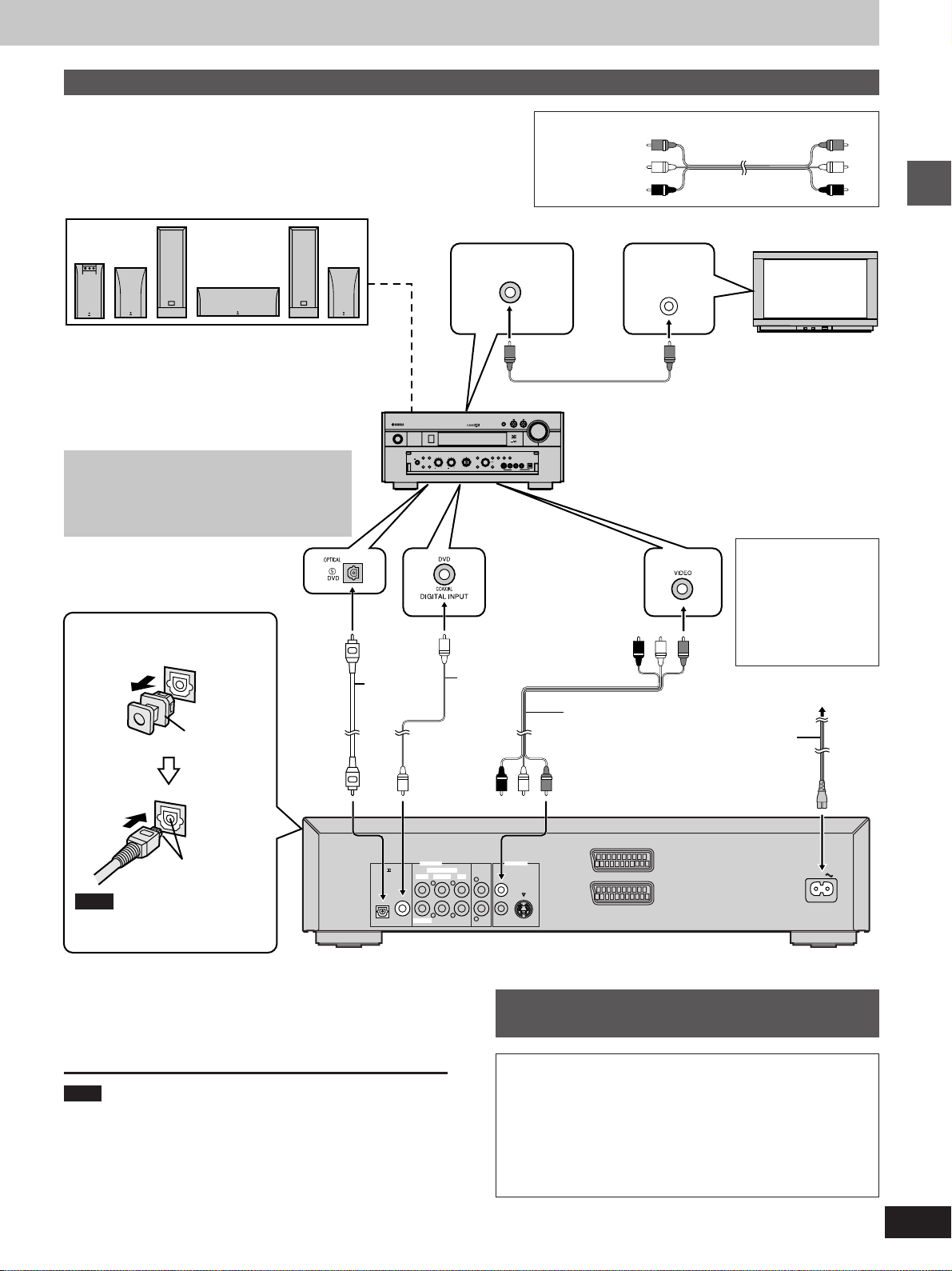
A
Connecting an AV amplifier with a built-in decoder
»
Before connection
³Do not connect the AC mains lead until all other connections are complete.
³Refer to the amplifier’s operating instructions.
MONITOR OUT
terminal
Speakers
³You can enjoy surround sound by connecting from
three to six speakers.
Example: Six speakers
³If you do not connect a subwoofer, it is advisable to
connect main speakers (L/R) capable of producing
bass of less than 100 Hz.
Do not connect the unit’s video output
through a video cassette recorder
STANDBY
/ON
NATURAL SOUND AV RECEIVER RX–V3000
SPEAKERS
A
SILENT
BASS
EXTENSION
PHONES
B
PROCESSOR
DIRECT
BASS TREBLE REC OUT/ZONE 2
SOURCE
EFFECT
/REMOTE
DVD
MD/TAPE
CD-R
D-TV/LD
TUNER
CABLE
SAT
CD
6CH
VCR 1
PHONO
INPUT
VCR 2/DVR
VIDEO AUX
The video from this unit may not be played correctly
due to copy-guards if you connect a video cassette
recorder between the unit and your television.
DIGITAL INPUT
(OPTICAL) terminal
Note when connecting the
optical digital audio cable
Optical
digital
audio cable
Do not bend
when
Coaxial
cable
connecting.
Remove the
dust cap
OR
Audio/video cable (included)
Yellow (VIDEO)
White (L)
Red (R)
VOLUME
INPUT
INPUT MODE
PRESET
TUNING
/TUNING
MODE
FM/AM
MEMORY
MAN'L/AUTO FM AUTO/NAN'L MONO
EDIT
S VIDEO VIDEO L R OPTICALAUDIO
DSP
PROGRAM
VIDEO AUX
AV amplifier
DIGITAL INPUT
(COAXIAL) terminal
VIDEO INPUT
terminal
Audio/video cable
(included)
Television
VIDEO
IN
Getting started
Video cable
FOR UNITED KINGDOM ONLY
READ THE CAUTION FOR THE AC
MAINS LEAD ON
PAGE 3 BEFORE
CONNECTION.
To household mains socket
(AC 220–240 V, 50 Hz)
AC mains lead
(included)
Align the plug with
the terminal
Note
Keep the dust cap and reattach
when not using the terminal.
Change PCM Down Conversion, Dolby Digital, DTS
Digital Surround, and MPEG to suit the equipment
(á pages 24 and 28).
Note
You cannot use DTS Digital Surround decoders not suited to DVDVideo.
PCM / DIGITAL
DTS
COAXIALOPTICAL
SUBWOOFER
6CH DISCRETE
SURROUND MAINCENTER
AV1
VIDEO OUTAUDIO OUT
VIDEO
MIXED 2CH
1L
LL
RR
S VIDEO
2
R
AV2
AC IN
Back of the unit
Connection to digital audio
C
»
equipment without a decoder
You can still enjoy audio using the connections described
above. Make the following settings (á pages 24 and 28).
Digital Audio Output
Select “On”
PCM Down Conversion
Select “Yes”.
Dolby Digital/DTS Digital Surround/MPEG
Select “PCM”.
7
S VIDEO
AV1
AV2
VIDEO
MIXED 2CH
COAXIALOPTICAL
PCM / DIGITAL
DTS
1L
2
VIDEO OUTAUDIO OUT
6CH DISCRETE
SURROUND MAINCENTER
SUBWOOFER
R
RR
LL
Connection
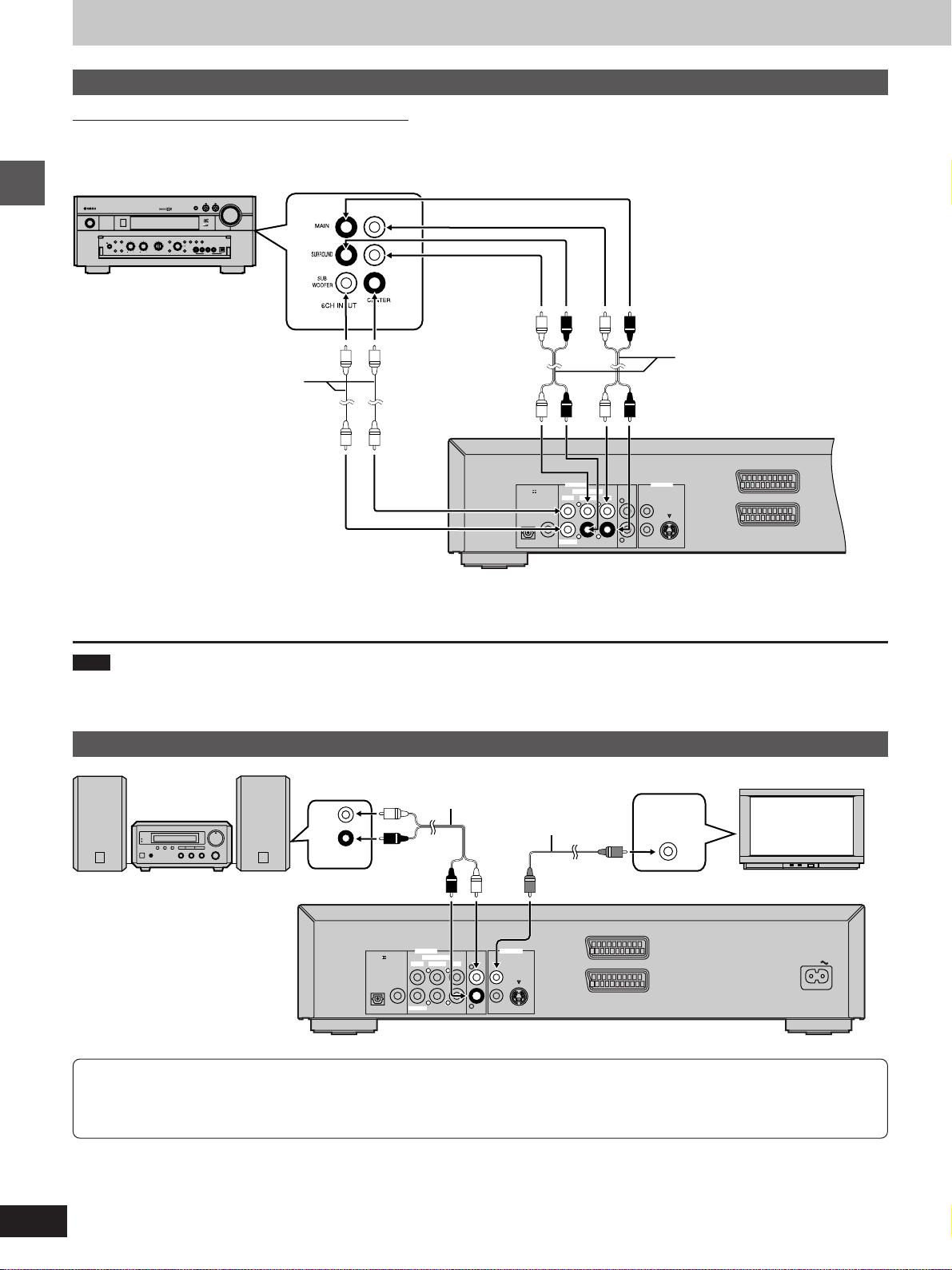
B
Connecting an AV amplifier with 5.1-channel audio input terminals
»
Be sure to switch the amplifier to ANALOG input.
³Speaker connections (á page 7)
³Television connections (á pages 7 and 9)
AV amplifier
VOLUME
INPUT
INPUT MODE
PRESET
TUNING
SOURCE
EFFECT
/TUNING
MODE
FM/AM
MEMORY
/REMOTE
DVD
MD/TAPE
CD-R
D-TV/LD
MAN'L/AUTO FM AUTO/NAN'L MONO
EDIT
TUNER
CABLE
S VIDEO VIDEO L R OPTICALAUDIO
SAT
CD
6CH
DSP
VCR 1
PHONO
INPUT
PROGRAM
VCR 2/DVR
VIDEO AUX
VIDEO AUX
RL
STANDBY
/ON
NATURAL SOUND AV RECEIVER RX–V3000
SPEAKERS
A
SILENT
BASS
EXTENSION
PHONES
B
PROCESSOR
DIRECT
BASS TREBLE REC OUT/ZONE 2
Getting started
Audio cable
6CH INPUT
terminals
Audio cable
Back of the unit
Select “Multi-channel” and adjust the settings to suit the speakers you have connected (á page 27).
Note
Turn Virtual Surround off (á page 19) if you have connected a center speaker, rear speakers or a subwoofer, as well as the main speakers. Sound
will not come from the other speakers if Virtual Surround is on.
D
Analog connection to a 2-channel amplifier or system component
»
Television
Audio cable
L
Video cable
R
VIDEO
IN
AUX IN
2-channel amplifier or system component
Back of the unit
Select “2-channel”
(á page 24, Audio–Speaker
Setting).
PCM / DIGITAL
DTS
COAXIALOPTICAL
SUBWOOFER
6CH DISCRETE
SURROUND MAINCENTER
VIDEO OUTAUDIO OUT
MIXED 2CH
VIDEO
1L
LL
RR
S VIDEO
R
2
AV1
AV2
AC IN
To enjoy Dolby Pro Logic
³If you connect an amplifier that can decode Dolby Pro Logic, you will also need to connect center and rear speakers to enjoy surround
sound. Read the instructions for the equipment for connection details.
³Turn Virtual Surround off (á page 19). Dolby Pro Logic will not function correctly if Virtual Surround is on.
8
S VIDEO
AV1
AV2
VIDEO
MIXED 2CH
COAXIALOPTICAL
PCM / DIGITAL
DTS
1L
2
VIDEO OUTAUDIO OUT
6CH DISCRETE
SURROUND MAINCENTER
SUBWOOFER
R
RR
LL
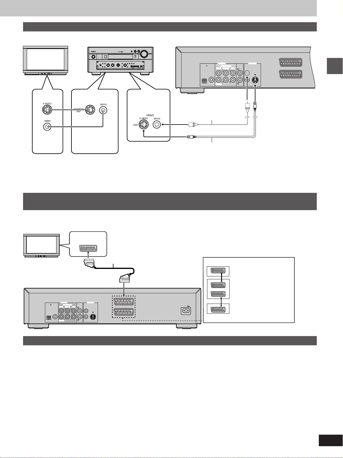
Connections using the S video terminal
Audio connections (á pages 7 and 8)
Television
STANDBY
/ON
NATURAL SOUND AV RECEIVER RX–V3000
SILENT
PHONES
AV amplifier
SPEAKERS
SOURCE
/REMOTE
A
B
DVD
D-TV/LD
CABLE
SAT
BASS
PROCESSOR
VCR 1
EXTENSION
DIRECT
VCR 2/DVR
VIDEO AUX
BASS TREBLE REC OUT/ZONE 2
INPUT MODE
TUNING
PRESET
EFFECT
MODE
/TUNING
MEMORY
FM/AM
MD/TAPE
CD-R
MAN'L/AUTO FM AUTO/NAN'L MONO
EDIT
TUNER
S VIDEO VIDEO L R OPTICALAUDIO
CD
6CH
DSP
PHONO
INPUT
PROGRAM
VIDEO AUX
VIDEO or S video
input terminal
VOLUME
Back of the unit
INPUT
Video cable
VIDEO
INPUT
terminal
MONITOR OUT
terminal
S video cable
The S-VIDEO terminal achieves a
more vivid picture than the VIDEO terminal by separating the chrominance
(C) and luminance (Y) signals. (Actual
results depend on the television.)
Connecting to a television and a video cassette recorder with a 21-pin SCART terminal
To improve picture quality, you can change the video signal output from the AV1
terminal from “Video” to either “S-Video” or “RGB” to suit the type of television you
are using (á page 24, Video—AV 1 Output).
SCART terminal
VCR
PCM / DIGITAL
DTS
COAXIALOPTICAL
SUBWOOFER
6CH DISCRETE
SURROUND MAINCENTER
21-pin SCART cable
AV1
VIDEO OUTAUDIO OUT
MIXED 2CH
VIDEO
1L
LL
RR
S VIDEO
R
2
AV2
AC IN
Example
VCR
AV1
AV2
AV1
Television
This unit
Video cassette
recorder
Getting started
Recording to MDs or cassette tapes
º Analog recording
You can record to an MD or cassette deck. Using analog connection
means sound will be unaffected by the copy guards found on DVDs.
To make an analog recording
Connect the recording equipment with an audio cable (á [D] page 8).
º Digital recording
You can record the digital signal directly onto an MD.
The signals on DVDs will be converted to 48 kHz/16 bit linear PCM.
Ensure the following conditions are met.
³There is no copy guard recorded on the disc.
³The recording equipment can handle a sampling frequency of
48 kHz/16 bit.
To make a digital recording
1. Connect the recording equipment with an optical or coaxial digital
audio cable (á [A] page 7).
2. When recording DVDs, change the digital audio output settings
(á page 24 and 28).
PCM Down Conversion: Yes
Dolby Digital/DTS Digital Surround: PCM
MPEG: PCM
Digital Audio Output: On (á page 24)
VIRTUAL SURROUND (V.S.S.): OFF (á page 19)
9
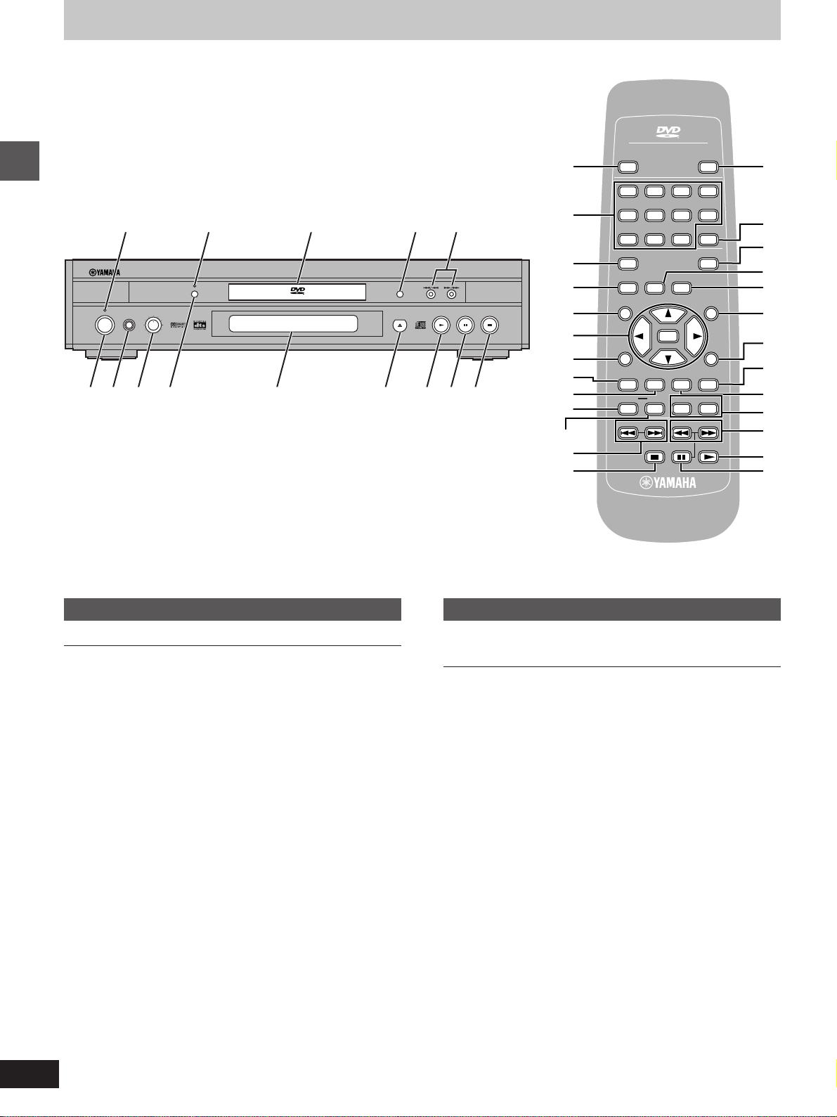
Control reference guide
>
AUDIO/VIDEO
POWER
Í
/I
1234
OPEN/CLOSE
9
1 2 3 4 5
NATURALSOUND DVD AUDIO / VIDEO PLAYERDVD-S1200
Getting started
STANDBY
PHONES
STANDBY
/ON
Main unit
LEVEL
010
VIDEO OFF
AUDIO/VIDEO
?
@
GROUP
;
A
B
C
D
6789:;<=>
E
F
G
H
6
5678
90
SET UP
VIDEO OFF
TOP MENU
ON SCREEN RETURN
SUBTITLE
PLAY MODE
REPEATA-BHP-V.S.S. SP-V.S.S.
SKIP
DVD
V756260
S
10
PAGEGROUP
ENTER
AUDIO ANGLE
SLOW/SEARCH
CANCEL
MARKER
MENU
PLAYPAUSESTOP
I
J
4
K
L
M
N
O
P
Q
8
7
Remote control
Page
1 Standby indicator (STANDBY)
When the unit is connected to the AC mains supply, this indicator
lights up in standby mode and goes out when the unit is turned on.
2 VIDEO OFF indicator . . . . . . . . . . . . . . . . . . . . . . . . . . . . . . . 14
3 Disc tray . . . . . . . . . . . . . . . . . . . . . . . . . . . . . . . . . . . . . . . . . 11
4 GROUP button (GROUP) . . . . . . . . . . . . . . . . . . . . . . . . . . . 14
5 Skip/Search buttons (:/6, 5/9) . . . . . . . . . . . . . 13
6 Stop button (º) . . . . . . . . . . . . . . . . . . . . . . . . . . . . . . . . . . . 11
7 Pause button (;) . . . . . . . . . . . . . . . . . . . . . . . . . . . . . . . . . . 11
8 Play button (1) . . . . . . . . . . . . . . . . . . . . . . . . . . . . . . . . . . . 11
9 Disc tray open/close button (<) . . . . . . . . . . . . . . . . . . . . . 11
: Display
; VIDEO OFF button (VIDEO OFF) . . . . . . . . . . . . . . . . . . . . . 14
< Headphone level control (LEVEL) . . . . . . . . . . . . . . . . . . . . 19
= Headphone jack (PHONES) . . . . . . . . . . . . . . . . . . . . . . . . . 19
> Standby/on switch (STANDBY/ON) . . . . . . . . . . . . . . . . . . . 11
Press to switch the unit from on to standby mode or vice versa. In
standby mode, the unit is still consuming a small amount of
power.
Buttons such as " function the same as the controls on the unit.
Page
? Numeric buttons (1–9, 0, S10) . . . . . . . . . . . . . . . . . . . . . . . 11
@ Setup button (SET UP) . . . . . . . . . . . . . . . . . . . . . . . . . . . . . 23
A Top menu button (TOP MENU) . . . . . . . . . . . . . . . . . . . . . . 11
B Cursor buttons (3, 4, 2, 1)/Enter button (ENTER) . . . . 11
C ON SCREEN button (ON SCREEN) . . . . . . . . . . . . . . . . . . . 20
D Play mode button (PLAY MODE) . . . . . . . . . . . . . . . . . . . . . 16
E Subtitle button (SUBTITLE) . . . . . . . . . . . . . . . . . . . . . . . . . 15
F Repeat mode button (REPEAT) . . . . . . . . . . . . . . . . . . . . . . 18
G A-B repeat button (A-B) . . . . . . . . . . . . . . . . . . . . . . . . . . . . 18
H Skip buttons (:, 9 SKIP) . . . . . . . . . . . . . . . . . . . . . . . 13
I Cancel button (CANCEL) . . . . . . . . . . . . . . . . . . . . . . . . . . . 14
J Marker button (MARKER) . . . . . . . . . . . . . . . . . . . . . . . . . . . 15
K Page button (PAGE) . . . . . . . . . . . . . . . . . . . . . . . . . . . . . . . 14
L Menu button (MENU) . . . . . . . . . . . . . . . . . . . . . . . . . . . . . . . 11
M Return button (RETURN) . . . . . . . . . . . . . . . . . . . . . . . . . . . 11
N Angle button (ANGLE) . . . . . . . . . . . . . . . . . . . . . . . . . . . . . 15
O Audio button (AUDIO) . . . . . . . . . . . . . . . . . . . . . . . . . . . . . . 15
P Headphone and Speaker V.S.S. buttons
(HP-V.S.S./SP-V.S.S.) . . . . . . . . . . . . . . . . . . . . . . . . . . . . . . 19
Q Slow/Search buttons (6, 5 SLOW/SEARCH) . . . . . . . 13
10
 Loading...