

Page 1

DRUM
TRIGGER
MODULE
OWNER’S MANUAL
ENDING
CLICKCLICK
KICK/MISC.
ACCOMPACCOMP
SNARE/CYMBAL
AUX INAUX IN
MIN
MIN
MAX
MAX
MASTER VOL.
MASTER VOL.
MUTE
MUTE
MUTE
MUTE
MAIN A MAIN B FILL AB FILL BA INTRO ENDING
3
OFF
DRUM
KIT
CHAIN
PATTERN SONG
MIS
C.
SNA
RE
KIC
K
CYM
BA
L
TEMPO
BEAT
MEASURE
INPUT
QUANT.
CLICK
DRUMDRUM
KIT
KIT
BASS
BASS
TMP TR
CHORDCHORD
CHO TR
R
H
YTH
M
RHYTHM
PAT TR
VOICEVOICE
UTILITY
UTILITY
STORE
STORE
P
ATTE
R
N
TTERN
SONGSONG
CHAIN
CHAIN
CLICK
PAGE
AGE
ERASE
SHIFTSHIFT
SOLO
SOLO
TR1
TR1
TR2
TR2
+
1/YES
1/YES
-
1/NO
1/NO
TEMPO
TEMPO
CYMBAL
MISC.
SNARE
MAIN B
FILL BA
MAIN A
FILL AB
INTRO
KICK
PAGE
AGE
TR
IG
G
E
R
TRIGGER
DRUM TRIGGER MODULE
Version 2.0
DRUM TRIGGER MODULE
Ve
rs
io
n
2.0
Page 2
FCC INFORMATION (U.S.A)
1. IMPORTANT NOTICE: DO NOT MODIFY THIS UNIT!
This product, when installed as indicated in the instructions contained in this manual, meets FCC requirements. Modifications not expressly
approved by Yamaha may void your authority, granted by the FCC, to use the product.
2. IMPORTANT: When connecting this product to accessories and/or another product use only high quality shielded cables.
Cable/s supplied with this product MUST be used. Follow all installation instructions. Failure to follow instructions could void your FCC
authorization to use this product in the USA.
3. NOTE: This product has been tested and found to comply with the requirements listed in FCC Regulations, Part 15 for Class "B" digital devices.
Compliance with these requirements provides a reasonable level of assurance that your use of this product in a residential environment will not
result in harmful interference with other electronic devices. This equipment generates/uses radio frequencies and, if not installed and used
according to the instructions found in the user's manual, may cause interference harmful to the operation of other electronic devices. Compliance
with FCC regulations does not guarantee that interference will not occur in all installations. If this product is found to be the source of interference,
which can be determined by turning the unit "OFF" and "ON", please try to eliminate the problem by using one of the following measures :
Relocate either this product or the device that is being affected by the interference.
Utilize power outlets that are on different branch (circuit breaker or fuse) circuits or install AC line filter/s.
In the case of radio or TV interference, relocate/reorient the antenna.
If the antenna lead-in is 300 ohm ribbon lead, change the lead-in to co-axial type cable.
If these corrective measures do not produce satisfactory results, please contact the your local retailer authorized to distribute this type of product.
If you can not locate the appropriate retailer, please contact Yamaha Corporation of America, Electronic Service Division, 6600 Orangethorpe
Ave, Buena Park, CA 90620
The above statements apply ONLY to those products distributed by Yamaha Corporation of America or its subsidiaries.
ADVARSEL!
Lithiumbatteri—Eksplosionsfare ved fejiatig håndtering.
Udskiftning må kun ske med batteri af samme fabrikat og type.
Levér det brugte batteri tilbage til leverandoren.
VARNING
Explosionsfara vid felaktigt batteribyte. Använd samma batterityp
eller en ekvivalent typ som rekommenderas av
apparattillverkaren. Kassera använt batteri enligt fabrikantens
instruktion.
VAROITUS
Paristo voi räjähtää, jos se on virheellisesti asennttu. Vaihda
paristo ainoastaan laitevalmistajan suosittelemaan tyyppiin.
Hävitä käytetty paristo valmistajan ohjeiden mukaisesti.
Caution
Always use the supplied Yamaha AC Adaptor to power DTX. The
use of an incompatible adaptor may pose a serious shock hazard.
Page 3

SPECIAL MESSAGE SECTION (USA)
This product utilizes batteries or an external power supply (adapter).
DO NOT connect this product to any power supply or adapter other
than one described in the manual, on the name plate, or specifically
recommended by Yamaha.
WARNING: Do not place this product in a position where anyone
could walk on, trip over, or roll anything over power or connecting
cords of any kind. The use of an extension cord is not recommended!
IF you must use an extension cord, the minimum wire size for a 25'
cord (or less) is 18 AWG. NOTE: The smaller the AWG number, the
larger the current handling capacity. For longer extension cords, consult a local electrician.
This Product should be used only with the components supplied or; a
cart, rack, or stand that is recommended by Yamaha. If a cart, etc., is
used, please observe all safety markings and instructions that accompany the accessory product.
SPECIFICATIONS SUBJECT TO CHANGE:
The information contained in this manual is believed to be correct at
the time of printing. However, Yamaha reserves the right to change or
modify any of the specifications without notice or obligation to update
existing units.
This product, either alone or in combination with an amplifier and
headphones or speaker/s, may be capable of producing sound levels
that could cause permanent hearing loss. DO NOT operate for long
periods of time at a high volume level or at a level that is uncomfortable. If you experience any hearing loss or ringing in the ears, you
should consult an audiologist. IMPORTANT: The louder the sound,
the shorter the time period before damage occurs.
ENVIRONMENTAL ISSUES:
Yamaha strives to produce products that are both user safe and environmentally friendly. We sincerely believe that our products and the
production methods used to produce them, meet these goals.
In keeping with both the letter and the spirit of the law, we want you to
be aware of the following:
Battery Notice:
This product MAY contain a small non-rechargeable battery which (if
applicable) is soldered in place. The average life span of this type of
battery is approximately five years. When replacement becomes necessary, contact a qualified service representative to perform the replacement.
This Product may also use "household" type batteries. Some of these
may be rechargeable. Make sure that the battery being charged is a
rechargeable type and that the charger is intended for the battery
being charged.
When installing batteries, do not mix old batteries with new, or with
batteries of a different type. Batteries MUST be installed correctly.
Mismatches or incorrect installation may result in overheating and
battery case rupture.
Warning:
Do not attempt to disassemble, or incinerate any battery. Keep all
batteries away from children. Dispose of used batteries promptly and
as regulated by the laws in your area.
Note: Check with any retailer of household type batteries in your area
for battery disposal information.
Some Yamaha products may have benches and/or accessory mounting fixtures that are either supplied with the product or as optional
accessories. Some of these items are designed to be dealer assembled or installed. Please make sure that benches are stable and
any optional fixtures (where applicable) are well secured BEFORE
using.
Benches supplied by Yamaha are designed for seating only. No other
uses are recommended.
NOTICE:
Service charges incurred due to lack of knowledge relating to how a
function or effect works (when the unit is operating as designed) are
not covered by the manufacturer's warranty, and are therefore the
owners responsibility. Please study this manual carefully and consult
your dealer before requesting service.
PLEASE KEEP THIS MANUAL
92-BP
Disposal Notice:
Should this Product become damaged beyond repair, or for some
reason its useful life is considered to be at an end, please observe all
local, state, and federal regulations that relate to the disposal of products that contain lead, batteries, plastics, etc. If your dealer is unable
to assist you, Please contact Yamaha directly.
NAME PLATE LOCATION:
The name Plate is located on the bottom of the product. The model
number, serial number, power requirements, etc., are located on this
plate. You should record the model number, serial number, and the
date of purchase in the spaces provided below and retain this manual
as a permanent record of your purchase.
Model
Serial No.
Purchase Date
Page 4

Page 5
Your DTX will give you years of reliable service if you follow the simple rules given below:
Location
Do not expose the instrument to the following
conditions, to avoid deformation, discoloration,
or more serious damage.
Direct sunlight, such as near a window.
High temperatures, for example, near a heat
source, outdoors, or in a car during the daytime.
Excessive humidity.
Excessive dust.
Strong vibrations.
Power Supply
Always use the supplied Yamaha AC Adaptor
(PA-1207, PA-3B or an equivalent) to power your
DTX. Other adaptors may cause damage to the
DTX. Also, make sure that the adaptor you have
is appropriate for the AC mains supply voltage in
the area where you intend to use the DTX.
Turn the power OFF and unplug the AC adaptor
when the instrument is not in use.
Unplug the AC adaptor during electrical storms.
Avoid plugging the AC adaptor used with the
DTX into the same AC mains outlet as appliances
with high power consumption, such as electric
heaters or ovens. Also avoid using multi-plug
adaptors since these can result in reduced sound
quality and possibly damage.
Turn off the power before making or breaking
connections.
To avoid damage to the instrument and other
devices to which it is connected (a sound system,
for example), always turn the power switches of
all related devices OFF before connecting or
disconnecting audio and MIDI cables.
Electrical Interference
The DTX contains digital circuitry and may cause
interference or noise if placed too close to TV
sets, radios, or similar equipment. If such a
problem does occur, move the DTX further away
from the affected equipment.
Memory Back-up
The DTX contains a special long-life battery that
retains the contents of its internal RAM memory
even when the power is turned OFF. The backup battery should last for several years. When the
back-up battery needs to be replaced, the
message “ERR-Low battery” will momentarily
appear on the display when you turn the power
ON. When this happens, have the back-up
battery replaced by qualified Yamaha service
personnel.
DO NOT ATTEMPT TO REPLACE THE BACKUP BATTERY YOURSELF.
Transfer important data from your DTX to a
MIDI data recorder such as the Yamaha MDF2
MIDI Data Filer for safe long-term storage.
Yamaha cannot be held responsible for data loss
caused by battery failure or improper operation
of the DTX.
Service and Modification
The DTX contains no user-serviceable parts.
Opening the case and/or tampering with the
internal circuitry can lead to irreparable damage
and will void the warranty. Refer all maintenance
to qualified Yamaha service personnel.
Handling and Transport
Never apply excessive force to the controls,
connectors, or other parts of the instrument.
Always plug and unplug any cables by gripping
the connector, not the cord itself. Disconnect all
cables before moving the instrument.
Dropping the DTX or otherwise subjecting it to
strong physical shocks can damage it. Handle it
with care.
Cleaning
Clean the cabinet and panel with a soft dry cloth.
A slightly damp cloth may be used to remove
stubborn grime and dirt.
Do not use solvents such alcohol, benzine, or
thinner to clean the cabinet or panel.
Avoid placing vinyl objects on top of the
instrument. Vinyl can stick to and discolor the
surface.
Third-party Software
Yamaha cannot take any responsibility for
software produced for this product by third-party
manufacturers. Please direct any comments about
such software to the manufacturer or their
agents.
Yamaha is NOT responsible for damage caused by
improper handling or operation.
1
Page 6
INTRODUCTION
○○○○○○○○○○○○○○○○○○○○○○○○○○○○○○○○○○○○○○○○○○○○○○○○○○○○○○○○○○○○○○○○○
Welcome to the Yamaha DRUM TRIGGER MODULE DTX—this is a COMPLETELY NEW type of drum
trigger module with Yamaha’s high quality AWM (Advanced Wave Memory) tone generation system and
sequencer functions. It is equipped with the features and capability required for professional recordings,
rehearsals, and practice sessions as well as live performances.
In order to take full advantage of the DTX, please read this manual carefully and try out all of the
examples set forth. Also, always keep this manual in a safe place for further reference.
ABOUT THIS MANUAL
○○○○○○○○○○○○○○○○○○○○○○○○○○○○○○○○○○○○○○○○○○○○○○○○○○○○○○○○○○○○○○○○○
This manual consists of 2 sections: Getting Started and Feature Reference.
Getting Started
This section describes the basic steps you need to quickly plug and play with a set up using the DTX. A
general explanation of the DTX is also available in the “Overall Structure and Modes” section (P.18) .
Feature Reference
This section describes each function in detail. You can use it as a dictionary to look up functions or
answers to your questions. The Table of Contents (P.4) or the Index (P.140) will help you look up words,
features and functions.
Page references are also made throughout this section for your quick reference.
DESCRIPTIONS
○○○○○○○○○○○○○○○○○○○○○○○○○○○○○○○○○○○○○○○○○○○○○○○○○○○○○○○○○○○○○○○○○
The following icons are used throughout this manual to draw attention to important points and
information where necessary.
A—This icon indicates more detailed information of a feature or function.
C—This icon warns of possible hardware damage, software malfunction, or any other serious
problem that may occur due to improper operation or set up.
INSIDE THIS PACKAGE
○○○○○○○○○○○○○○○○○○○○○○○○○○○○○○○○○○○○○○○○○○○○○○○○○○○○○○○○○○○○○○○○○
●The DTX Owner’s Manual (This book)
●Quick Guide
●Yamaha AC Power Adaptor PA-1207 or PA-3B
2
Page 7

What is a DTX?
In addition to the conventional drum trigger functions, the DTX is a multi-function digital instrument
with an AWM 2 tone generator which is compatible with the GM standard providing high quality sounds,
rhythm machine functions with many rhythm styles, and sequencer fucntions enabling you to create an
entire song. You can use the DTX in many situations such as studio production, live performances and
rhythm practice.
Rhythm machine
function
Sequencer
function
The Main Features of the DTX
○○○○○○○○○○○○○○○○○○○○○○○○○○○○○○○○○○○○○○○○○○○○○○○○○○○○○○○○○○○○○○○○○
Drum trigger
function
AWM2 tone
generator
● Drum trigger functions allow you to designate detailed edits to each of the 12 input jacks for live
performances and other purposes.
● 32 practical preset drum kits as well as memory space for 32 user drum kits to assign your original set of
voices to.
● 928 high quality drum voices and an AWM tone generator (triggering up to 32 voices at one time) with
128 keyboard sounds that comply to the GM System Level 1.
● Edit functions to edit the effect, volume and pitch of each drum voice.
● Complete sequencer functions to create or record the rhythm and backing patterns of your preference
(pattern record) using a pad or a MIDI keyboard as well as to easily create an entire song using patterns or
preset styles (song record).
● Chain functions to conveniently conduct live performances and rhythm practice effectively.
● Large LCD and LED displays, transport buttons and a Data scroll wheel that makes programming faster
and easier.
● 4 volume sliders to control the volume of the entire system as well as each rhythm or accompaniment part.
● Groove checking functions to check the difference (percentage: %)in timing or “groove” feel.
● Various MIDI functions to enhance the DTX system by connecting to MIDI devices or computers.
● As a high quality drum voice module.
● To practice rhythm by playing to the patterns.
● As a rhythm machine.
● To conduct a solo live performance by creating an accompaniment in advance.
● As a 16-part GM tone generator for computer music and create or edit songs any way you want by using
the pattern or song functions.
● ...or in any other way you choose! The DTX is a talented reliable partner for all musicians.
3
Page 8
Contents
○○○○○○○○○○○○○○○○○○○○○○○○○○○○○○○
Controls and Functions ............................................................ 6
Setting Up ................................................................................. 9
Getting Started
Getting Started ........................................................................ 14
Overall Structure and Modes .................................................. 18
Drum or Percussion Sounds and Drum Kits ....................................... 18
Pattern and Song ................................................................................ 19
Triggering .......................................................................................... 20
The Modes of the DTX ....................................................................... 21
Basic Operation ....................................................................... 22
Entering a mode ................................................................................. 22
Tips on the LCD ................................................................................ 25
PAGE¡ and PAGE⁄ Buttons ............................................................. 26
QCursor Buttons .................................................................. 26
Data Scroll Wheel .............................................................................. 27
+1/YES and -1/NO Buttons ................................................................ 27
Transport Buttons .............................................................................. 27
Feature Reference
Drum Kit Play Mode ............................................................... 30
Entering Drum Kit Play Mode ............................................................ 30
Selecting a Drum Kit .......................................................................... 30
Drum Kit Trigger Edit Mode ................................................... 32
Entering the Drum Kit Trigger Edit Mode .......................................... 32
Drum Kit Trigger Edit mode (Page structure and operation) .............. 33
1 Kit name ................................................................................ 35
2 PAD Type (pad type) .............................................................. 35
3 Auto Set ................................................................................. 36
4 PAD Gain ............................................................................... 36
6 VelRange (velocity range) ....................................................... 37
7 VelCurve (velocity curve) ....................................................... 38
8 Self Rej (self rejection) ............................................................ 39
9 Reject (rejection) .................................................................... 39
10 Spec Rej (specific rejection) .................................................... 40
11 Note= (note numbers settings) ............................................... 40
12 Note= (gate time) ................................................................... 42
13 Note= (MIDI channel) ............................................................ 42
14 KeyOn.................................................................................... 43
15 VelXFade (velocity cross-fade) ............................................... 44
16 RIMKeyOn ............................................................................. 44
17 RIM Vel (RIM velocity) ........................................................... 45
18 PAD Func (pad function) ....................................................... 45
19 FS Func (FS function) ............................................................ 46
20 FS MIDI (FS MIDI channel) ................................................... 47
21 FS HHcls (FS hi-hat control) .................................................. 47
22 FC Func (hi-hat control function) .......................................... 47
23 FC MIDI (hi-hat control channel) .......................................... 47
24 FC Sens (hi-hat control sensitivity) ........................................ 48
25 HH Ctrl (hi-hat control) ......................................................... 48
26 In 9 to 10 (Input 9 to 10) ....................................................... 48
27 In 11 to 12 (Input 11 to 12) ................................................... 48
28 Copy INP (copy input) ........................................................... 48
29 Copy TRG (copy trigger) ........................................................ 49
30 Edit (edit recall) ..................................................................... 49
31 SetChord= (setting the note number by chord) ...................... 49
Drum Kit Voice Edit Mode ..................................................... 50
Entering Drum Kit Voice Edit Mode .................................................. 51
Drum Kit Voice Edit Mode (Page structure and operation) ................. 51
1 VCE (voice) ............................................................................ 53
2 Volume .................................................................................. 53
3 Pan ......................................................................................... 54
4 Pitch ...................................................................................... 54
5 Rev send (send reverb) ........................................................... 55
6 Modify ................................................................................... 55
7 Filter ...................................................................................... 56
8 Decay ..................................................................................... 56
9 Key mode ............................................................................... 57
10 AlterGrp (alternate group) ...................................................... 57
11 Key Off .................................................................................. 58
12 Out Port ................................................................................. 58
13 REV Rtn (reverb return) ......................................................... 58
14 REV Type (reverb type) .......................................................... 59
15 REV Time (reverb time) ......................................................... 59
16 PC Ch= (transmit program change) ........................................ 59
17 BK CH= (transmit bank select) ............................................... 60
18 CC Ch= (transmit control change: volume) ............................ 60
19 CC Ch= (transmit control change: pan) .................................. 61
20 CC Ch= (transmit control change) ......................................... 61
21 Root Note ............................................................................... 62
Chain Play Mode ..................................................................... 63
Entering the Chain Play Mode ............................................................ 63
Selecting a Chain ............................................................................... 64
Switching the Steps ............................................................................ 64
Chain Edit Mode ..................................................................... 65
Entering the Chain Mode ................................................................... 65
The Chain Edit Mode (Page structure and operation) ......................... 66
1 Name (chain name) .................................................................. 67
2 Chain create or revise ............................................................... 67
3 Edit recall ................................................................................. 68
Store Mode .............................................................................. 69
Entering Store Mode .......................................................................... 69
Drum Kit Store Mode .................................................................. 69
Chain Store Mode ....................................................................... 69
Storing ............................................................................................... 70
Copying the Drum Kit or Chain ......................................................... 70
Pattern Play Mode ................................................................... 71
The Concept of “pattern” ................................................................... 71
Types of Patterns ......................................................................... 71
Style ............................................................................................ 71
Section ........................................................................................ 71
User Patterns ............................................................................... 72
Entering Pattern Play Mode ................................................................ 72
Selecting a Pattern .............................................................................. 72
Playing a Pattern ................................................................................ 74
Volume Adjustment ........................................................................... 75
Adjusting the Tempo ......................................................................... 76
Click (metronome) ............................................................................. 76
Muting or Soloing Each Track ............................................................ 77
Selecting the Chords .......................................................................... 78
Pattern Record Mode .............................................................. 80
Recording .................................................................................... 80
Pattern Job Mode .................................................................... 88
Entering Pattern Job Mode ................................................................. 88
The Pattern Job Mode (page structure and operation) ........................ 88
1 Copy (Pat/Dest): pattern copy ................................................. 90
2 Quantize (quantization) ........................................................... 91
3 CrTrNote (clear specific note) .................................................. 91
4 ClrTrack (clears a track) ........................................................... 92
5 ClearPat (clear pattern) ............................................................ 92
6 Pgm=
(selects the voices of a chord, bass or rhythm track) ...................
7 Pat Name (pattern name) ......................................................... 92
92
Song Play Mode ....................................................................... 93
The Concept of “song” ....................................................................... 93
Track Structure ........................................................................... 93
Sequence Track ........................................................................... 93
Backing Track ............................................................................. 93
Types of Songs ............................................................................ 93
Entering Song Play Mode ................................................................... 94
Selecting a Song ................................................................................. 94
Playing a Song .................................................................................... 95
Volume Adjustment ........................................................................... 96
Adjusting the Tempo ......................................................................... 96
Click (metronome) ............................................................................. 96
The Mute/Solo Function .................................................................... 97
Groove Check Function ..................................................................... 97
Song Record Mode .................................................................. 99
Recording .................................................................................... 99
Song Job Mode ...................................................................... 107
Entering Song Job Mode .................................................................. 107
The Song Job Mode (page structure and operation) ......................... 107
1 Copy (Song/Dest): pattern copy .......................................... 108
2 Quantize (quantization) ....................................................... 109
4
Page 9
3 ClrTrack (clear track) ........................................................... 109
4 Clr Song (clear song) ............................................................ 109
5 PgmCh (select the voices of each channel) ........................... 110
6 VolCh (channel volume) ...................................................... 110
7 PanCh (channel pan) ........................................................... 110
8 PlayMode ............................................................................. 110
9 B Lnr TR (bass linear track mode) ........................................ 111
10 Pat Mute (pattern track mute mode) .................................... 111
11 SongName ............................................................................ 111
Utility Mode .......................................................................... 112
Entering Utility Mode ...................................................................... 112
The Utility Mode (page structure and operation) .............................. 112
1 SYSTEM ............................................................................... 114
2 EditMode ............................................................................. 114
3 LinkMode ............................................................................ 115
4 Lrn Mode (learn mode) ........................................................ 115
5 SldrMode (slider mode) ....................................................... 116
6 Bypass .................................................................................. 116
7 JumpRcnt (jump to recent page) .......................................... 116
8 FC offset .............................................................................. 117
9 Ma to Aux (main output to auxiliary output) ....................... 117
10 Inc Func (increase function) ................................................ 117
11 Dec Func (decrease function) ............................................... 117
12 MIDI .................................................................................... 117
13 DeviceNo (device number) ................................................... 117
14 Receive SysX (receiving system exclusive data) ..................... 117
15 Receive PC (receiving program change data) ........................ 118
16 RecvCh10 All (receiving channel message through MIDI data from channel 10) . 118
17 RecvCh10 PC (receive program change through channel 10) 118
18 SendHH (send hi-hat control change) .................................. 118
19 LocalClt (local control) ......................................................... 118
20 DumpTime ........................................................................... 119
21 MergeOut ............................................................................. 119
22 Dump Out (bulk data send) ................................................. 119
23 P/C->KIT (program change table) ....................................... 120
24 EQ (equalizer) ...................................................................... 120
25Lo Mi Hi (gain) ..................................................................... 121
26 Lo Freq (low frequency) ....................................................... 121
27 Mid Freq (mid frequency) .................................................... 121
28 Hi Freq (high frequency) ...................................................... 121
29 SEQ (sequencer) .................................................................. 122
30 Click Hi ............................................................................... 122
31 Click Mid ............................................................................. 122
32 Click Lo ............................................................................... 122
33 Click Out ............................................................................. 123
34 PlyClick (play click) ............................................................. 123
35 Tempo ................................................................................. 123
36 Count ................................................................................... 123
37 GrvCheck (groove check) ..................................................... 124
38 Break TB (break top/bottom) ................................................ 124
39 MIDIctrl (MIDI control) ....................................................... 125
40 SyncMode (synchronization mode) ...................................... 125
41 MULTI (multi-timbre) .......................................................... 126
42 MastTune (master tune) ....................................................... 126
43 Program ............................................................................... 126
44 Volume ................................................................................ 127
45 Pan ....................................................................................... 127
46 Pitch .................................................................................... 128
47 RevSend (Reverb Send) ........................................................ 128
Getting Started
Feature
Reference
Drum Kit Play Mode
Drum Kit
Trigger Edit Mode
Drum Kit
Voice Edit Mode
Chain Play Mode
Chain Edit Mode
Store Mode
Pattern Play Mode
Pattern
Record Mode
Pattern Job Mode
Song Play Mode
Song Record Mode
Appendix
MIDI ...................................................................................... 129
MIDI Data Format ............................................................................ 134
Troubleshooting ............................................................................... 136
Error Messages ................................................................................. 138
Specifications ................................................................................... 139
Index ............................................................................................... 140
Drum Voice List ............................................................................... 143
GM Keyboard Voice List .................................................................. 147
Drum Kit List ................................................................................... 148
Preset Style List ................................................................................ 165
Preset Song List ................................................................................ 165
Drum Kit Trigger Edit Parameter (Blank Chart) ............................... 166
Drum Kit Voice Edit Parameter (Blank Chart) .................................. 166
MIDI Implementation Chart ............................................................ 168
Song Job Mode
Utility Mode
Appendix
5
Page 10

Controls and Functions
DRUM
KIT
BASS
TMP TR
CHORD
CHO TR
PAT TR
VOICE
UTILITY
STORE
SONG
CHAIN
CLICK
KICK/MISC.
AGE
ERASE
SHIFT
SOLO
TR1
TR2
1/YES
1/NO
TEMPO
CYMBAL
MISC.
SNARE
MAIN B
FILL BA
ENDING
MAIN A
FILL AB
INTRO
KICK
AGE
ACCOMP
SNARE/CYMBAL
AUX IN
MIN
MAX
MASTER VOL.
Top Panel
○○○○○○○○○○○○○○○○○○○○○○○○○○○○○○○○○○○○○○○○○○○○○○○○○○○○○○○○○○○○○○○○○
AUX IN
TEMPO BEAT
MEASURE
INPUT
ACCOMP
SNARE/CYMBAL
QUANT.
CLICK
OFF
CHAIN
DRUM KIT
PATTERN SONG
MISC.
CYMBAL
SNARE
KICK
MAIN A MAIN B FILL AB FILL BA INTRO ENDING
MAX
MIN
MASTER VOL.
! LCD (Liquid Crystal Display) (P.25)
The large multi-function LCD panel shows all the
prompts and parameters needed to operate the DTX
easily and efficiently.
Each screen of parameters is called a display “page.”
The various pages of each mode can be picked using the
+1/YES and -1/NO buttons.
Within a page, there is a blinking letter, word, number,
or symbol referred to as the “cursor”. A “focus area”
refers to the parameter you can adjust. Use the
Q cursor buttons to move the cursor to the
focus area.
" LED (Light Emitting Diode) Display (P.31)
The large two-digit LED display shows the selected
drum kit number so you can be sure of your selection
especially during live performances with poor stage
lighting.
# MASTER Volume Slider (P.31)
This volume control slider adjusts the total volume of
sound output from the PHONES jack, the OUTPUT (L/
MONO and R) jacks.
$ AUX IN Volume Slider (P.11)
This volume control slider adjusts the volume of the
6
incoming signals of the AUX IN jack (CD player, tape
recorder, etc.)
3
MUTE
MUTE
MUTE
MUTE
CLICK
KICK/MISC.
DRUM
KIT
CHAIN
SONG
PATTERN
TRIGGER
VOICE
UTILITY
STORE
PAGE
ERASE
MAIN A
FILL AB
−
1/NO
INTRO
TEMPO
PAGE
MAIN B
FILL BA
+
1/YES
ENDING
SHIFT
TR1
MISC.
BASS
TMP TR
SNARE
CHORD
CHO TR
TR2
CYMBAL
RHYTHM
PAT TR
KICK
SOLO
CLICK
Version
DRUM TRIGGER MODULE
2.0
% ACCOMP SNARE/CYMBAL Volume Slider (P.31)
This volume control slider adjusts the volume of the
accompaniment, snare drum, or cymbals of a song or
pattern.
& CLICK KICK/MISC. Volume Slider (P.31)
This volume control adjusts the volume of the
metronome click sound, kick, or other musical
instruments.
' DRUM KIT Button (P.30)
Press this button to put the DTX into Drum Kit Play
mode.
( CHAIN Button (P.63)
Press this button once to put the DTX into Chain mode.
Press twice this button to put the DTX into Chain Edit
mode.
) SONG Button (P.94)
Press this button once to put the DTX into Song mode.
Press twice this button to put the DTX into Song Job
mode.
* PATTERN Button (P.72)
Press this button once to put the DTX into Pattern
mode. Press twice this button to put the DTX into
Pattern Job mode.
Page 11

+ TRIGGER Button (P.32)
Press this button to put the DTX into Drum Kit Trigger
Edit mode.
, VOICE Button (P.51)
Press this button to put the DTX into Drum Kit Voice
Edit mode. This button also acts as an “audition” button
which allows you to listen to a voice without actually
changing it while you are editing.
9 BASS TMP TR (SNARE) Button (P.77)
This button turns the Bass Track or Tempo Track of the
song ON or OFF. Press this button while holding, the
SHIFT button, to mute the SNARE part of the rhythm.
: RHYTHM PAT TR (KICK) Button (P.77)
This button turns the Rhythm Track or Pattern Track of
the song ON or OFF. Press this button while holding,
the SHIFT button, to mute the KICK part of the rhythm.
- UTILITY Button (P.112)
Press this button to put the DTX into Utility mode.
. STORE Button (P.69)
Press this button to put the DTX into Drum Kit Store
mode or Chain Store mode.
/ PAGE¡/ERASE (MAIN A) Button (P.26, 73)
This button selects the previous page. In Pattern mode,
press this button while holding the SHIFT button to
select the MAIN A pattern. In recording mode, press
this button to erase data.
0 PAGE⁄ (MAIN B) Button (P.26, 73)
This button selects the next page. In Pattern mode,
press this button while holding the SHIFT button to
select the MAIN B pattern.
1 ‡(FILL AB) Button (P.26, 73)
This button allows you to move backward among the
focus areas in a page. In Pattern mode, press this button
while holding the SHIFT button to select the FILL AB
Pattern.
2 ¶(FILL BA) Button (P.26, 73)
This button allows you to move forward among the
focus areas in a page. In Pattern mode, press this button
while holding the SHIFT button to select the FILL BA
Pattern.
3 -1/NO (INTRO) Button (P.27, 73)
This button decreases the value of a parameter. In
Pattern mode, press this button while holding the SHIFT
button to select the INTRO Pattern.
4 +1/YES (ENDING) Button (P.27, 73)
This button increases the value of a parameter. In
Pattern mode, press this button while holding the SHIFT
button to select the ENDING Pattern.
; CHORD CHO TR Button (P.77)
This button turns the Chord Track of the song ON or
OFF.
< SOLO Button (P.78)
Press the rhythm part buttons while holding this button
to listen to the soling of a rhythm part.
= CLICK Button (P.76)
This button turns the metronome ON or OFF.
> PAUSE Button (P.74, 95)
This button pauses the song. The song will start where
it was stopped when the button is pressed again.
? REWIND Button (P.74, 95)
This button moves the location indicator backward by a
measure. Press continuously to rapidly rewind.
@ START/STOP Button (P.74, 95)
This button starts or stops playback or recording.
A FORWARD Button (P.74, 95)
This button steps the indicator forward by a measure.
Press continuously to fast forward.
B RECORD Button (P.81)
This button switches the DTX into Record-ready (standby) mode.
C Data Scroll Wheel (P.27)
The Data Scroll Wheel allows rapid control over the
parameters of the focus area.
For fine single-step adjustments, you may want to use
the +1/YES and -1/NO buttons described above.
5 TEMPO Button (P.76)
This button directly selects the TEMPO focus area.
6 SHIFT Button (P.73, 77)
This button sets a secondary function, for example
selecting a section or muting part of a rhythm, by
pressing another specific button while holding this
buttn.
7 TR1 (MISC.) Button (P.77)
This button turns TR1 (Track 1) of the song ON or OFF.
Press this button while holding, the SHIFT button, to
mute the MISC. (other instruments) part of the rhythm.
8 TR2 (CYMBAL) Button (P.77)
This button turns TR2 (Track 2) of the song ON or OFF.
Press this button while holding, the SHIFT button, to
mute the CYM (cymbal) part of the rhythm.
7
Page 12

Rear Panel
12/11
INPUT ATTENUATION
10/9 KICK
AUX OUT
8 H.HAT
7 CRASH
6 RIDE
5 TOM4
4 TOM3
3 TOM2
2 TOM1
1 SNARE
DC IN 12V
POWER
L/MONO
PHONES
AUX IN
FOOT SW
H.HAT
CONTROL
OUTPUT
MIDI
CONTRAST
OUT
IN
○○○○○○○○○○○○○○○○○○○○○○○○○○○○○○○○○○○○○○○○○○○○○○○○○○○○○○○○○○○○○○○○○
INPUT ATTENUATION
12/11
10/9 KICK
8 H.HAT
7 CRASH
6 RIDE
5 TOM4
4 TOM3
3 TOM2
2 TOM1
1 SNARE
POWER
DC IN 12V
R L R L/MONO
AUX OUT
! POWER Switch (P.12)
Press this button to turn the DTX ON or OFF.
" INPUT ATTENUATION Switches
These switches adjust the input level when pads of
varying output levels are connected. The input level
increases when the switch is lowered. Try this when the
volume does not respond to the pad played or when a
double-triggering occurs to one tap.
# DC IN Jack (P.12)
Connect the AC adapter (Yamaha PA-1207, PA-3B or an
equivalent) included in this package.
A
The Yamaha PA-3 CANNOT be connected.
$ 12/11 Input (P.9)
Connects with an optional pad. If you use a stereo phone
plug to connect the DTX and two pads, two triggers can
be input. If you use monaural phone plugs, only 11 is
available to use.
OUTPUT
PHONES
AUX IN
FOOT SW
H.HAT
CONTROL
CONTRAST
OUT
( OUTPUT L/MONO and R Jacks (P.10)
Use these jacks to connect to external amplifiers or mixers
using a monaural phone plug. For monaural playback,
connect to L/MONO. For stereo playback, connect to
both L/MONO and R.
) PHONES Jack (P.9)
Connect a stereo headphone to this jack to monitor the
DTX.
* AUX IN Jack (P.11)
Use this jack to input data from an external audio device
using a miniature stereo phone plug. This is convenient
when you are playing to music from a CD or cassette
tape.
+ FOOT SW Jack (P.9)
Connect a footswitch (Yamaha FS50 or FC5) to this plug.
Select the footswitch function you want to use from the
19th FS Function page in Drum Kit Trigger Edit mode (P.
46).
MIDI
IN
% 10/9 KICK Input (P.9)
Connects with an optional pad. If you use a stereo phone
plug to connect the DTX and two pads, two triggers can
be input. If you use monaural phone plugs, only 9 is
available to use.
& 1 SNARE to 8 H.HAT Inputs (P.9)
Connect stereo phone plugs to input from trigger or
switch type pads (Yamaha TP80S or PCY80S). Use a
monaural phone plug for plain trigger input.
A
Plugging a monaural phone plug when the power is ON
may cause a reversed phase and the switch may malfunction. In
this case, turn the power OFF, reconnect the plug and turn the
power ON again.
' AUX OUT L and R Jacks
This jack is used to separately output specific sound(s)
such as the kick and snare. To assign a sound to these
output jacks, select the Output Port on the 12th page in
Drum Kit Voice Edit mode (P.12). To assign a
metronome click to these output jacks, set the SEQ
ClickOut on the 27th page in Utility mode (P. 58).
8
, H.HAT CONTROL Jack (P.9)
Connect the hi-hat foot controller (Yamaha HH80 or
FC7) to this plug. You can use this as a MIDI controller
by changing the parameter on the 22nd Hi-hat Control
Function page in Drum Kit Trigger Edit mode (P. 47).
- CONTRAST Knob
This knob adjusts the contrast of the LCD.
. MIDI IN/OUT (P.9)
Use these connectors to send or receive MIDI data to or
from an external MIDI device. You can create a large
scale MIDI system by connecting the DTX to an external
MIDI tone generator or sequencer.
Page 13
Setting Up
INPUT ATTENUATION
10/9 KICK
AUX OUT
8 H.HAT
7 CRASH
6 RIDE
5 TOM4
4 TOM3
3 TOM2
2 TOM1
1 SNARE
DC IN 12V
POWER
L/MONO
PHONES
AUX IN
FOOT SW
H.HAT
CONTROL
OUTPUT
MIDI
CONTRAST
OUT
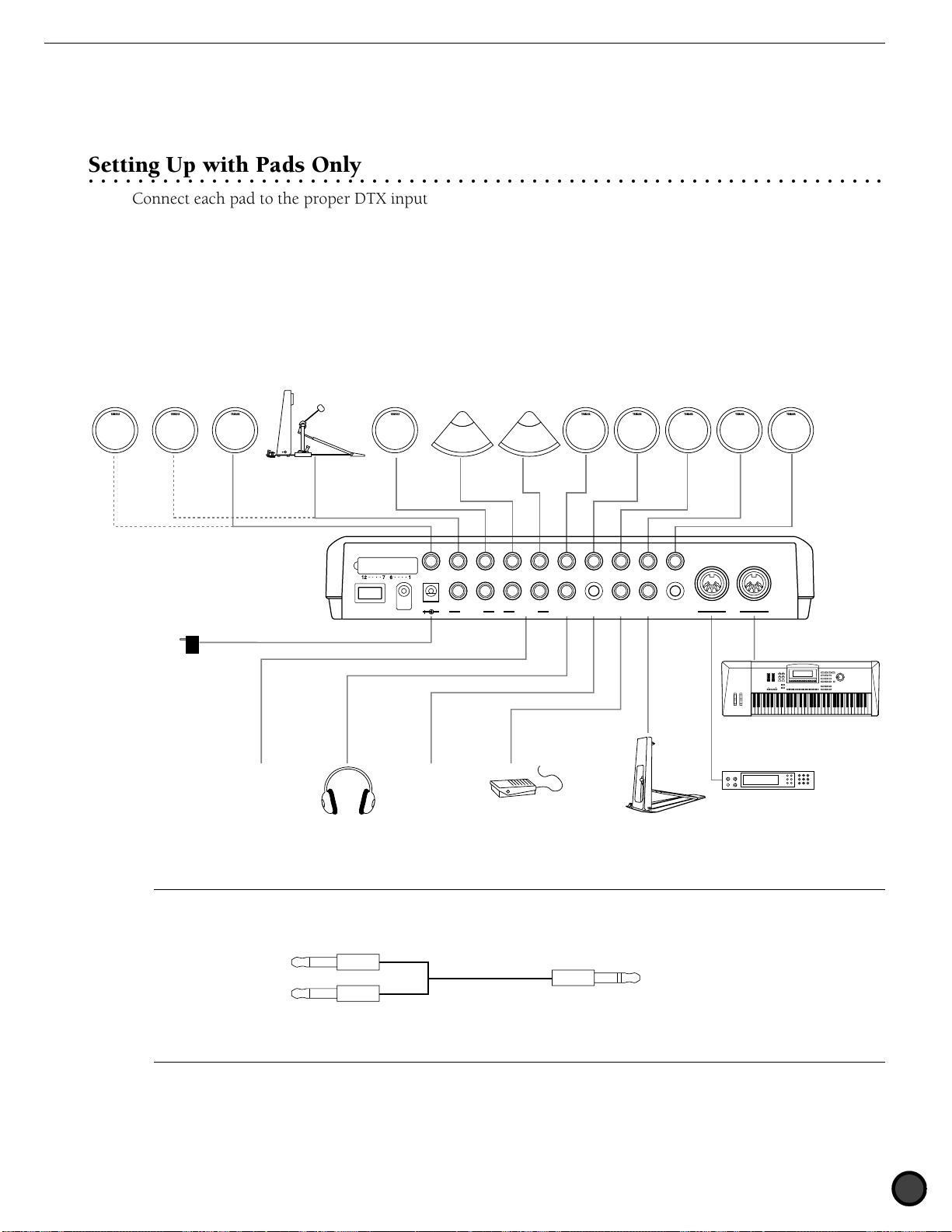
Setting Up with Pads Only
○○○○○○○○○○○○○○○○○○○○○○○○○○○○○○○○○○○○○○○○○○○○○○○○○○○○○○○○○○○○○○○○○
Connect each pad to the proper DTX input jack as shown below:
(This illustration is an example of the pads, triggers and devices that can be connected to the DTX. Refer to
P.8 for the types of pads or triggers that can be connected to each input jack.)
KP80,etc.TP80,etc.Additional Pads PCY80,etc. PCY80,etc. TP80,etc.TP80,etc. TP80,etc. TP80,etc. TP80,etc. TP80,etc.
INPUT ATTENUATION
12/11
10/9 KICK
8 H.HAT
7 CRASH
6 RIDE
5 TOM4
4 TOM3
3 TOM2
2 TOM1
1 SNARE
POWER
DC IN 12V
R L R L/MONO
AUX OUT
OUTPUT
PHONES
AUX IN
FOOT SW
H.HAT
CONTROL
CONTRAST
OUT
IN
MIDI
AC Power Adaptor
–
MIDIkeyboard,etc.
Audio output
Headphones
A
To further add a pad, use a conversion cable (which separates the stereo plug to two monaural plugs) for INPUT 10/9 and 12/11 which enables
you to enter two different trigger signals. For most preset drum kits, a cupped cymbal voice is set to INPUT 10 and asuitable percussion voice for
each preset drum kit is set to INPUT 11 and 12.
Two monaural plugs Stereo plug
CD Player,etc.
FS-50,etc.
HH80,etc.
MIDI tone generator,etc.
To the DTX Input 10/9 or 12/11To the pads
Conversion cable
9
Page 14
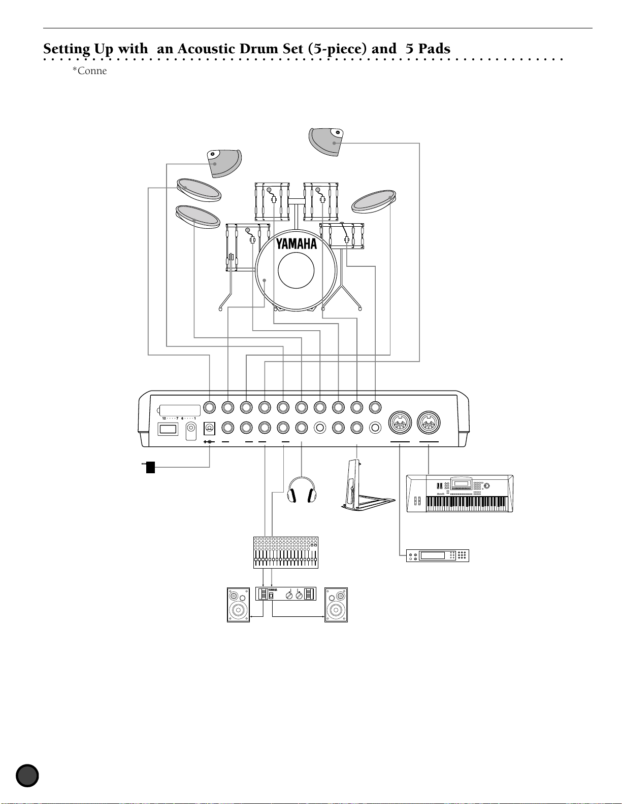
Setting Up with an Acoustic Drum Set (5-piece) and 5 Pads
12/11
INPUT ATTENUATION
10/9 KICK
AUX OUT
8 H.HAT
7 CRASH
6 RIDE
5 TOM4
4 TOM3
3 TOM2
2 TOM1
1 SNARE
DC IN 12V
POWER
L/MONO
PHONES
AUX IN
FOOT SW
H.HAT
CONTROL
OUTPUT
MIDI
CONTRAST
OUT
IN
○○○○○○○○○○○○○○○○○○○○○○○○○○○○○○○○○○○○○○○○○○○○○○○○○○○○○○○○○○○○○○○○○
*Connect each acoustic drum piece to a drum trigger pick-up (Yamaha DT10—not included) in advance.
(P.11)
Connect each drum trigger pick-up to the proper input jack as shown below:
AC Power Adaptor
INPUT ATTENUATION
POWER
12/11
10/9 KICK
8 H.HAT
7 CRASH
6 RIDE
DC IN 12V
R L R L/MONO
AUX OUT
OUTPUT
Headphones
Ch. 2Ch. 1
Mixer
Amplifier
Speaker Speaker
5 TOM4
PHONES
4 TOM3
3 TOM2
2 TOM1
1 SNARE
AUX IN
FOOT SW
H.HAT
CONTRAST
CONTROL
HH80
OUT
IN
MIDI
MIDI keyboard or other devices
MIDI tone generator/keyboard
or other devices
—
10
Page 15
Using the AUX IN jack
CLICK
KICK/MISC.
ACCOMP
SNARE/CYMBAL
AUX IN
MIN
MAX
MASTER VOL.
5 TOM4
4 TOM3
3 TOM2
PHONES
AUX IN
FOOT SW
The AUX IN jack (stereo mini jack) is located on the near panel. You can enter a sound source from a CD or cassette player
through this jack, mix it with the DTX sounds and send it out through the output jacks on the rear panel. This is convenient
when you practice a rhythm by playing to a tune or hold a band session. It is also posible to independently control the output
volume of the sound source coming in from the external device by using the AUX IN volume slider. By doing so you can
adjust the balance between the drum kits of the DTX and the external sound.
MAX
5 TOM4
4 TOM3
3 TOM2
PHONES
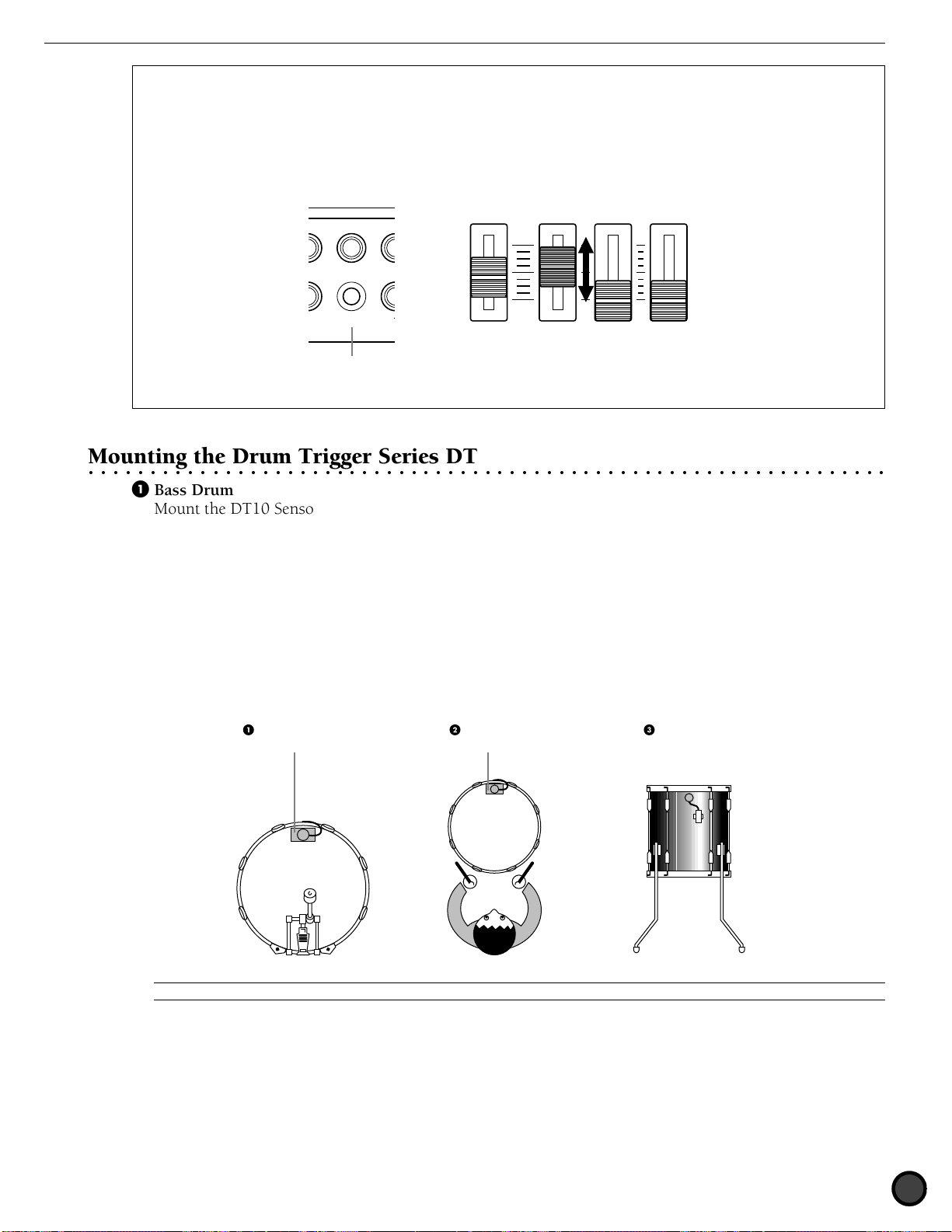
Mounting the Drum Trigger Series DT
○○○○○○○○○○○○○○○○○○○○○○○○○○○○○○○○○○○○○○○○○○○○○○○○○○○○○○○○○○○○○○○○○
AUX IN
AUX IN jack
FOOT SW
MASTER VOL.
MIN
AUX IN
ACCOMP
SNARE/CYMBAL
CLICK
KICK/MISC.
! Bass Drum
Mount the DT10 Sensor (trigger) on the batterhead of the bass drum close to, yet not touching the edge of
the rim.
" Snare
Mount the DT10 Sensor (trigger) on the batterhead of the snare close to, yet not touching the edge of the
rim across the player.
# Toms
Mount the DT10 Sensor (trigger) on the shell, close to, yet not touching the rim. Place the triggers away
from the influence of other drums (snare or toms), hi-hat, and cowbells.
Sticky tape Sticky tape
C
Be sure to connect the audio devices before turning all the related devices ON.
11
Page 16
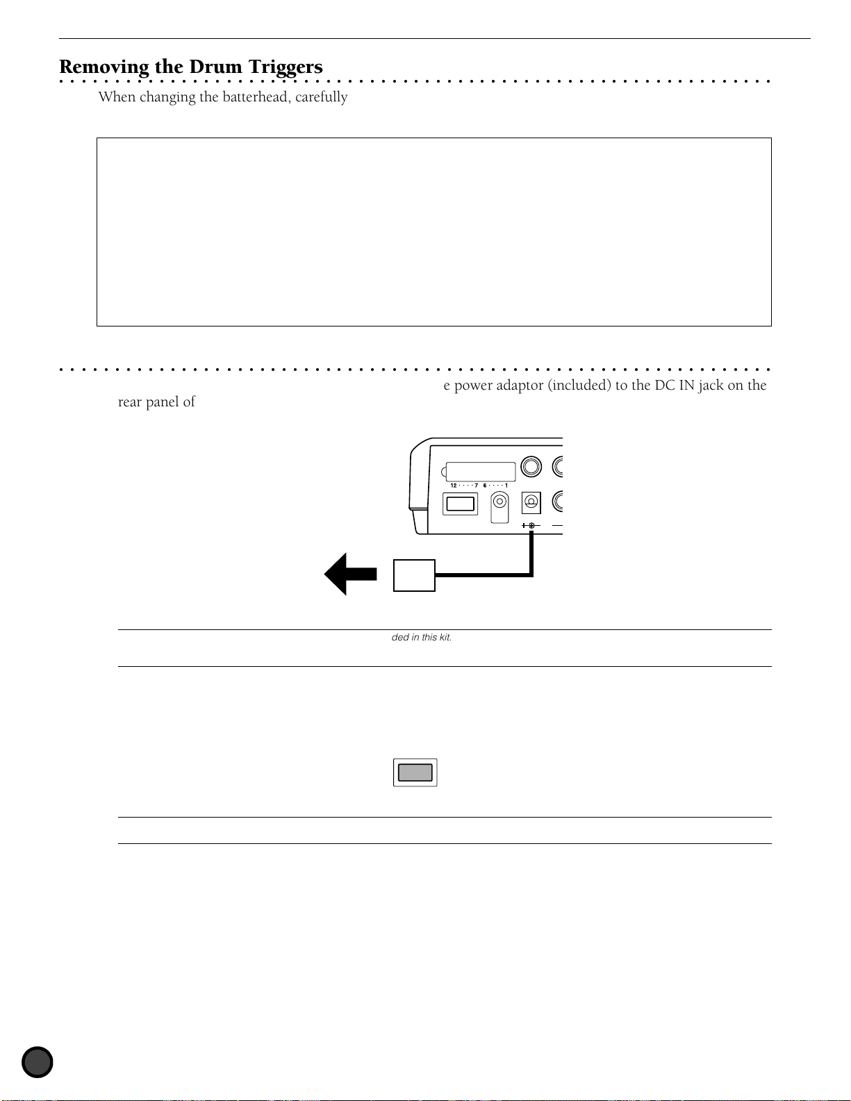
Removing the Drum Triggers
INPUT ATTENUATION
AUX OUT
DC IN 12V
POWER
POWER
○○○○○○○○○○○○○○○○○○○○○○○○○○○○○○○○○○○○○○○○○○○○○○○○○○○○○○○○○○○○○○○○○
When changing the batterhead, carefully remove the trigger sensor with a sharp object before loosening the
head. Take care not to pull the cord when you are removing the trigger.
ATTENTION
Make sure the surface of the batterhead or the shell where the trigger is mounted is free from dirt or grind. Clean the surface
with alcohol in advance.
To prevent broken trigger cords caused by the vibration of the drum rim, cover and fix the triggers and cords onto the
batterhead with sticky tape.
Irregular vibration and sustained resonance on the batterhead or the shell may cause double-triggering. This can be prevented
by applying a mute (such as the Yamaha Ring Mute) to the batterhead and controlling the excessive vibration.
Once you have removed the drum trigger and want to mount it again, be sure to completely remove the used sticky tape and
apply new sticky tape. Using used sticky tape may cause bad pick-up response or double-triggering.
The Power Supply
○○○○○○○○○○○○○○○○○○○○○○○○○○○○○○○○○○○○○○○○○○○○○○○○○○○○○○○○○○○○○○○○○
! Make sure the POWER switch is OFF and connect the power adaptor (included) to the DC IN jack on the
rear panel of the DTX, then plug the adaptor into a convenient wall AC outlet.
INPUT ATTENUATION
12/11
10/9 KICK
POWER
Wall AC outlet
AC power adaptor
C
DTX, and might pose a serious shock hazard. Also, unplug the power adaptor from the electric outlet when the DTX is not in use for long periods of
time.
Be sure to use PA-1207, PA-3B or an equivalent included in this kit. Using an improper power adaptor may cause irreparable damage to the
DC IN 12V
R
AUX OUT
" Make sure all the devices such as the pads, external devices, or audio systems are connected correctly and
turn the POWER switch on the rear panel of the DTX, ON. When the power is turned on, the DTX
analyses the connections and optimizes the settings.
POWER
C
turning the system off, simply reverse the process.
To avoid speaker damage, make it a rule to turn the power on in the order of 1) the DTX, 2) mixers and amplifiers, 3) audio devices. When
12
Page 17

CHAPTER
1
Getting Started
This chapter describes the basic operations of the DTX.
Use this to get an overall image of the DTX and master the basic uses.
Getting Started ....................................................................................................... (P.14)
Overall Structure and Modes ................................................................................. (P.18)
Basic Operation ...................................................................................................... (P.22)
Page 18
Getting Started
KICK/MISC.
SNARE/CYMBAL
X
T
Y
D
A
M
A
H
A
D
R
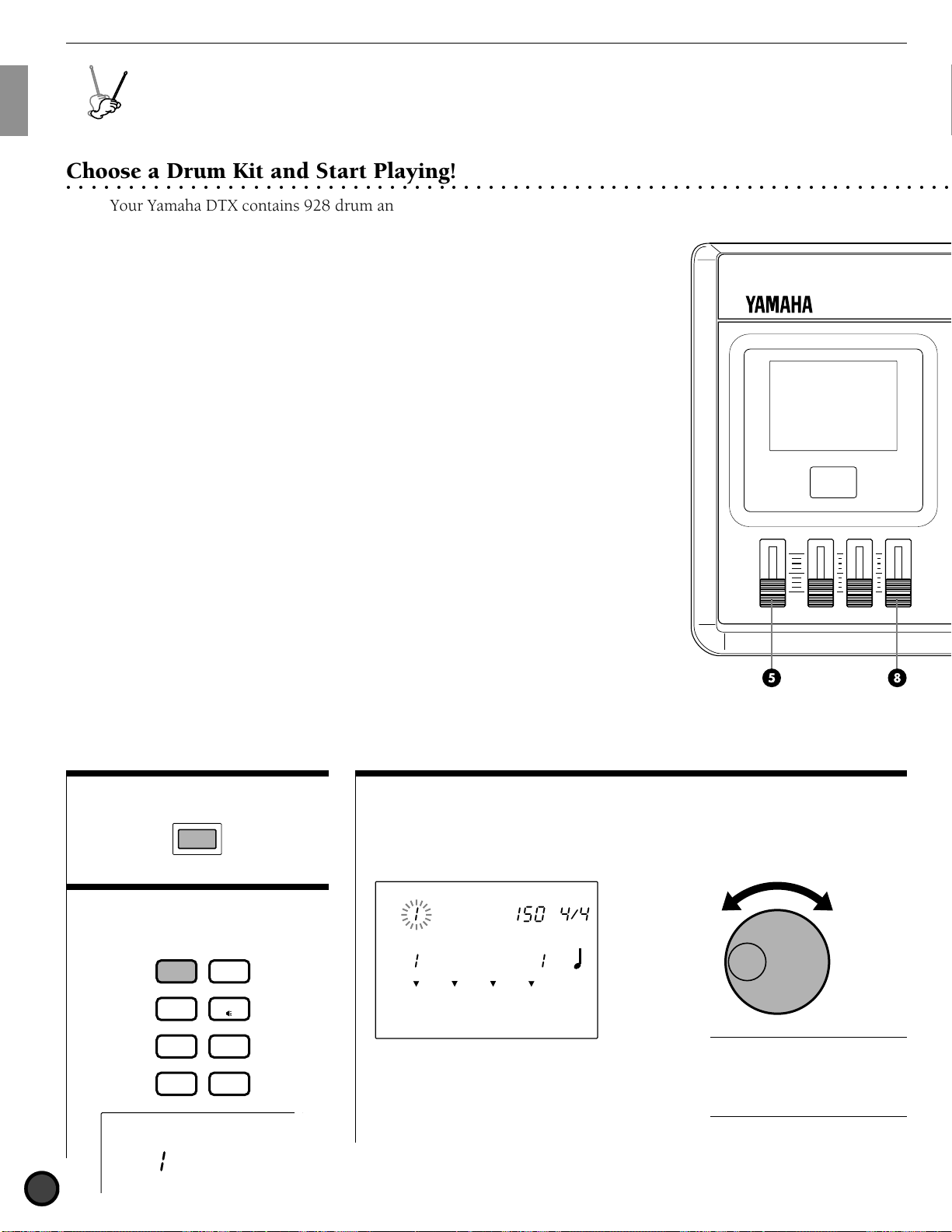
Choose a Drum Kit and Start Playing!
○○○○○○○○○○○○○○○○○○○○○○○○○○○○○○○○○○○○○○○○○○○○○○○○○○○○○○○○○○○○○○○○○○○○○○○○
E
L
U
D
O
Getting Started
M
U
R
M
E
G
T
R
G
I
Your Yamaha DTX contains 928 drum and percussion sounds. Drum
and percussion sounds make up a drum kit (drum voice) and the drum
kits are categorized by musical style. There are 64 drum kits: 32
preset drum kits and 32 user drum kits which enable you to enjoy
performances of various musical styles just by selecting a kit. You can
create your own drum kit (user drum kit) from scratch. (P.32)
The LCD illustrations in this manual are just examples used for the purpose of
A
explanation. The display is subject to change depending on the operation, mode, settings or
usage.
! Turn the power ON.
POWER
" Enter Drum Kit Play mode
by pressing the DRUM KIT
button.
DRUM
CHAIN
KIT
TRIGGER
VOICE
# Select a drum kit.
Press the Q cursor buttons
and move the cursor to the drum kit
number.
DRUM KIT
TEMPO BEAT
Acoustkt
SONG
MEASURE
CityDogs
MISC.
CYMBAL
SNARE
KICK
CLICK
MAX
MIN
MASTER VOL.
AUX IN
ACCOMP
SNARE/CYMBAL
KICK/MISC.
Rotate the Data Scroll Wheel to select
the drum kit you want to use.
CLICK
SONG
PATTERN
UTILITY
STORE
DRUM KIT
Acoustkt
14
A
The drum kit number is also
displayed on the LED. No. 1 to No. 32
are the user drum kits, and No. 33 to
No. 64 are the preset drum kits. The
user drum kits No. 1 to No. 32 contain
readily usable drumsounds.
Page 19
Getting Started
CLICK
ACCOMP
AUX IN
MIN
MAX
MASTER VOL.
CLICK
CLICK
KICK/MISC.
ACCOMP
SNARE/CYMBAL
AUX IN
MIN
MAX
MASTER VOL.
TMP TR
CHO TR
RHYTHM
PAT TR
CLICK
ERASE
CYMBAL
MISC.
SNARE
MAIN B
FILL BA
ENDING
MAIN A
FILL AB
INTRO
KICK
○○○○○○○○○○○○○○○○○○○○○○○○○○○○○○○○○○○○○○○○○○○○○○○○○○○○○○○○○○○○○○○○○○○○○○○○
DRUM
KIT
CHAIN
SONG
PATTERN
CLICK
TRIGGER
UTILITY
STORE
VOICE
PAGE
ERASE
MAIN A
FILL AB
−
1/NO
INTRO
TEMPO
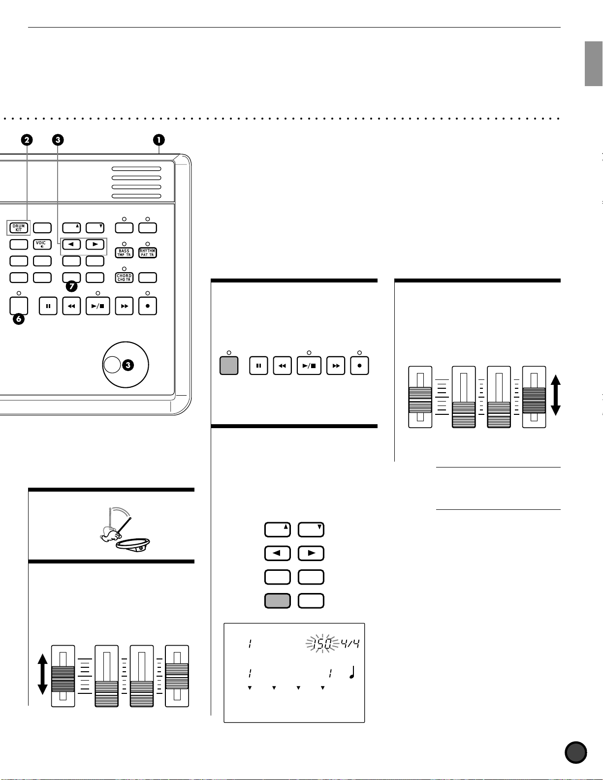
$ Play the pads
PAGE
MAIN B
FILL BA
+
1/YES
ENDING
SHIFT SOLO
TR1 TR2
MISC.
BASS
TMP TR
SNARE
CHORD
CHO TR
CYMBAL
RHYTHM
PAT TR
KICK
& Play to the Click
Press the CLICK button to start the
metronome. Press the CLICK button
again to stop the metronome.
CLICK
( Change the Volume of the
Click
Use the CLICK volume slider to adjust
the volume of the metronome click.
MAX
MIN
' Change the Tempo of the
MASTER VOL.
AUX IN
ACCOMP
SNARE/CYMBAL
CLICK
KICK/MISC.
Click
Press the TEMPO button to move the
cursor to TEMPO on the LCD. Rotate
the Data Scroll Wheel or use the +1/
YES and -1/NO buttons to set the
click tempo between [=30 to 299.
A
You can also adjust the beat or
quantization by moving the cursor to the
BEAT or CLICK focus area and using
the Data Scroll Wheel or the +1/YES and
-1/NO buttons.
% Adjust the volume
Use the MASTER Volume Slider to
adjust the volume of the entire drum
kit.
DRUM KIT
MASTER VOL.
MAX
MIN
AUX IN
ACCOMP
SNARE/CYMBAL
CLICK
KICK/MISC.
MISC.
CYMBAL
SNARE
KICK
PAGE
ERASE
MAIN A
FILL AB
−
INTRO
TEMPO
1/NO
PAGE
MAIN B
FILL BA
+
1/YES
ENDING
SHIFT
TEMPO BEAT
Acoustic
SONG
MEASURE
CityDogs
CLICK
15
Page 20

Getting Started
CLICK
KICK/MISC.
ACCOMP
SNARE/CYMBAL
AUX IN
MIN
MAX
MASTER VOL.
CLICK
KICK/MISC.KICK/MISC.
ACCOMPACCOMP
SNARE/CYMBALSNARE/CYMBAL
AUX IN
MIN
MAX
MASTER VOL.
Play to a Pattern!
○○○○○○○○○○○○○○○○○○○○○○○○○○○○○○○○○○○○○○○○○○○○○○○○○○○○○○○○○○○○○○○○○○○○○○○○
Your Yamaha DTX features rhythm machine functions containing 660
preset patterns (110 styles x 6 sections) and 100 user patterns. One
pattern consists of rhythm part, bass part and chord part. Each preset
style contains 6 sections (MAIN A, MAIN B, FILL AB, FILL BA, INTRO,
and ENDING).
Try out the various patterns.
! Enter Pattern Play mode.
Press the PATTERN button to enter
Pattern Play mode.
DRUM KIT
TEMPO BEAT
Acoustic
PATTERN
MEASURE
CLICK
RP Hop
MISC.
MISC.
CYMBAL
CYMBAL
SNARE
SNARE
KICK
KICK
MAIN A
A
The Drum Kit Play mode and the
Pattern Play mode will appear on the
same display.
" Select a style or pattern.
After making sure the cursor is located
on the style or pattern number, rotate
the Data Scroll Wheel to select a style
or pattern number.
DRUM KIT
TEMPO BEAT
GM jazz
PATTERN
MEASURE
CLICK
RP Candy
MISC.
CYMBAL
SNARE
KICK
MAIN A
A
The style or pattern number
focus area is automatically selected and
blinks when you enter Pattern Play
mode.
# Start to play the pattern.
Press the START/STOP button to play
a pattern. You can play the pads to
the pattern.
CLICK
A
It is possible to change to
another style or pattern while a pattern
or style is playing.
$ Adjust the tempo.
Press the TEMPO button to move the
cursor to TEMPO on the LCD.
Rotate the Data Scroll Wheel to
change the tempo of the pattern
between a range of [ =30 to 299.
DRUM KIT
PAGE
ERASE
MAIN A
FILL AB
−
INTRO
TEMPO
1/NO
PAGE
MAIN B
FILL BA
+
1/YES
ENDING
SHIFT
TEMPO BEAT
GM jazz
PATTERN
MEASURE
CLICK
CMaj7 ___ _
MISC.
CYMBAL
SNARE
KICK
MAIN A
% Adjust the volume of the
pattern.
Use the MASTER volume slider to
adjust the volume of the entire
system. Also, use the ACCOMP
volume slider to adjust the volume of
the accompaniment of the pattern.
This is convenient when you want to
listen only to the rhythm.
MAX
MIN
MASTER VOL.
AUX IN
ACCOMP
SNARE/CYMBAL
KICK/MISC.
CLICK
16
A
Each style has a default tempo
value. Therefore, even if you change
the tempo, once you stop playing and
select a different style, the tempo will
return to the default value of the newly
selected style. However, when you
select a different style in the middle of a
pattern playback, the tempo will not
change.
Page 21
Getting Started
BASS
TMP TR
CHORD
CHO TR
PAT TR
SOLO
TR1
TR2
CYMBAL
MISC.
SNARE
KICK
BASS
TMP TR
CHORD
CHO TR
PAT TR
SOLO
TR1
TR2
CYMBAL
MISC.
SNARE
KICK
RHYTHM
BASS
TMP TR
CHORD
CHO TR
PAT TR
SOLO
TR1
TR2
CYMBAL
MISC.
SNARE
KICK
AGE
ERASE
SHIFT
1/YES
1/NO
TEMPO
MAIN B
FILL BA
ENDING
MAIN A
FILL AB
INTRO
AGE
TMP TR
CHO TR
RHYTHM
PAT TR
TRIGGER
TTERN
CLICK
ERASE
CYMBAL
MISC.
SNARE
MAIN B
ENDING
MAIN A
INTRO
KICK
○○○○○○○○○○○○○○○○○○○○○○○○○○○○○○○○○○○○○○○○○○○○○○○○○○○○○○○○○○○○○○○○○○○○○○○○
DRUM
KIT
CHAIN
SONG
PATTERN
CLICK
TRIGGER
VOICE
UTILITY
STORE
PAGE
ERASE
MAIN A
FILL AB
−
1/NO
INTRO
TEMPO
& Switch sections.
Press the MAIN A, MAIN B, FILL AB,
FILL BA, INTRO, or ENDING buttons
while holding the SHIFT button to
change the sections of the currently
selected style. The name of the
section currently playing is displayed
on the bottom level of the LCD.
PAGE
MAIN B
FILL BA
+
1/YES
ENDING
SHIFT SOLO
TR1 TR2
MISC.
BASS
TMP TR
SNARE
CHORD
CHO TR
CYMBAL
RHYTHM
PAT TR
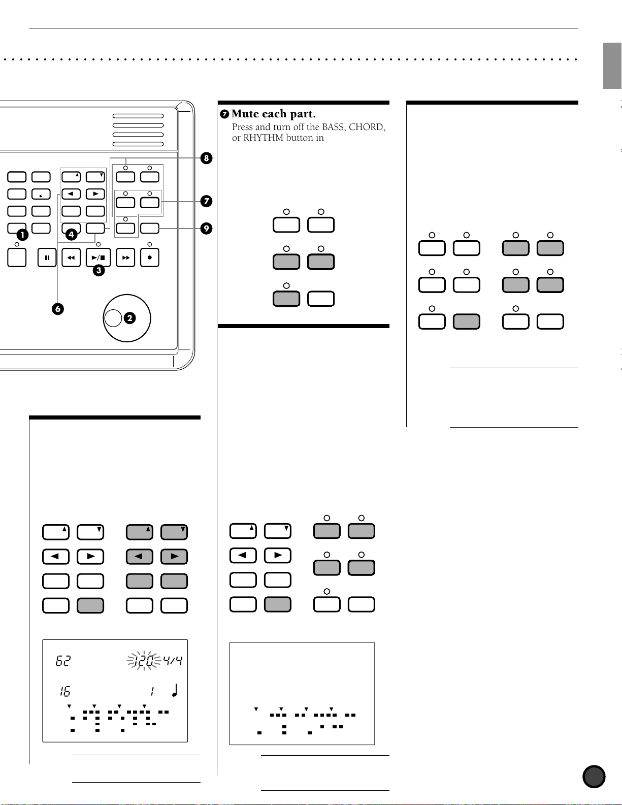
' Mute each part.
Press and turn off the BASS, CHORD,
or RHYTHM button individually to
mute each part. You can mute parts
which are not necessary when you
practice. To cancel the mute, press
the same button again. The LED
above each button will light up when
the part is ON.
KICK
TR1 TR2
CYMBALMISC.
BASS
TMP TR
SNARE KICK
CHORD
CHO TR
RHYTHM
PAT TR
SOLO
( Mute each rhythm track.
The rhythm part consists of KICK,
) Soloing each part.
You can play each part of the rhythm
solely and mute the other parts in one
step. This is convenient when you
want to audition each rhythm part or
voice. Play each rhythm part solely by
pressing the SNARE, KICK, CYMBAL,
or MISC. button while holding SOLO.
To cancel the solo function, press the
SOLO button again.
+
TR1
MISC.
BASS
TMP TR
SNARE
CHORD
CHO TR
CYMBAL
RHYTHM
TR1
MISC.
BASS
TMP TR
SNARE
CHORD
CHO TR
TR2
CYMBAL
RHYTHM
PAT TR
KICK
SOLO
While holding
the SOLO button ...
TR2
PAT TR
KICK
SOLO
SNARE, CYMBAL, and MISC. (other
instruments) tracks. You can mute
each track. Press the SNARE, KICK,
CYMBAL, or MISC. button while
holding SHIFT to mute each track.
Use this to practice a particular part
such as the snare or kick part by
A
The DTX is factory preset to
automatically switch the drum kit to its
most appropriate pattern each time the
pattern is changed. To keep the drum
kit from switching to its preset pattern,
turn the PC function of the RecvCh 10
PC in Utility Mode off.
muting the part and substitute it by
playing the snare or kick pad by
yourself. The LCD will hide the
“Data” indicators of the muted track
and “MUTE” will appear on the right
side of the rhythm track. To cancel,
press the same button while holding
SHIFT.
PAGE
ERASE
MAIN A
FILL AB
−
INTRO
TEMPO
MISC.
CYMBAL
SNARE
KICK
+
FILL AB
PAGE
ERASE
MAIN A
FILL AB
−
1/NO
INTRO
TEMPO
TEMPO BEAT
MEASURE
ERASE
MAIN A
FILL AB
−
INTRO
TEMPO
DRUM KIT
PATTERN
MISC.
CYMBAL
SNARE
KICK
PAGE
MAIN B
FILL BA
+
1/NO
1/YES
ENDING
SHIFT
While holding
the SHIFT button ...
GM jazz
CMaj7 _ _
A
Each style contains 6 sections
which have a variety of usage. Refer to
P.71for details.
PAGE PAGE
MAIN B
FILL BA
+
1/YES
ENDING
SHIFT
CLICK
PAGE
MAIN B
FILL BA
+
1/NO
1/YES
ENDING
SHIFT
While holding
the SHIFT button ...
FILL AB
A
The lower part of the LCD
displays the data indicators of each
+
TR1
MISC.
BASS
TMP TR
SNARE
CHORD
CHO TR
rhythm track in a 16-beat format. Refer
to P.19, 77 for details.
TR2
CYMBAL
RHYTHM
PAT TR
KICK
SOLO
MUTE
17
Page 22

Getting Started
X
T
Y
D
A
M
A
H
A
D
R
E
L
U
D
O
M
U
M
T
R
G
I
Overall Structure and Modes
R
E
G
The following describes how the DTX works in detail.
Drum or Percussion Sounds and Drum Kits
○○○○○○○○○○○○○○○○○○○○○○○○○○○○○○○○○○○○○○○○○○○○○○○○○○○○○○○○○○○○○○○○○
Your DTX has a total of 928 drum voices (drum and percussion sounds). These drum and percussion sounds
are categorized and called “drum kits.” Drum kits consist of drum voices which are stored in correspondense
to MIDI note numbers (P.41) There are 29 user drum kits and 32 preset drum kits which are frequently used,
each categorized by music style. You can assign drum and percussion sounds to register 32 user drum kits.
Each drum and percussion sound can be edited in many ways such as changing the pitch, adding a reverb,
etc. You can use the chain function to set drum kits in the order of your preference and play them back in
this order. This function is useful for live performances.
Your DTX also contains 128 normal keyboard voices. These voices are used to add bass or chord parts to the
DTX rhythm pattern. It is also possible to play a melody or obbligato by changing a part (MIDI channel).
The tone generator section complies to the GM standard level 1 and can be used to play back the
commercially available Standard MIDI Files by an external sequencer.
928 drum voices
Kick
Cymbal
Hi-hat
Snare
Drum Kit Voice Edit
128 normal keyboard voices
MIDI note numbers
13 to 84
Preset drum kits (33 to 64)
User drum kits (1 to 32)
Drum Kit
Trigger Edit
Pattern or song
MIDI file playback
Tone generator
Parts and Voices
Part
1
Melody
2
and others
3
4
5
Chord
6
Bass
7
8
Melody
and others
9
Drum (rhythm)
10
11
12
Melody
13
and others
14
15
16
MIDI
channel
10
11
12
13
14
15
16
1
2
3
4
5
6
7
8
9
Voices
to use
Keyboard
voice
Drum voice
Keyboard
voice
Piano
Organ
Guitar
18
Bass part
Chord part
Melody part
Page 23
Getting Started
Pattern and Song
○○○○○○○○○○○○○○○○○○○○○○○○○○○○○○○○○○○○○○○○○○○○○○○○○○○○○○○○○○○○○○○○○
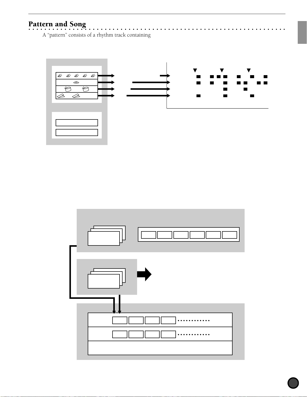
A “pattern” consists of a rhythm track containing various drum voices and a backing track containing the
chords and bass line which accompanies the rhythm. The rhythm pattern is displayed on the LCD in 4 parts:
KICK, SNARE, CYMBAL and MISC. (other instruments) enabling you to visually check the rhythm structure.
LCD display
Pattern
Rhythm pattern
MISC. (other instruments)
CYMBAL
SNARE
KICK
MISC.
CYMBAL
SNARE
KICK
MAIN A
+
Backing pattern
Chord
Bass
Your DTX contains 660 preset patterns (110 styles x 6 sections) with matching preset backings. 100 original
user patterns can be created and stored within the DTX. In the same manner as the drum kit, the patterns
can also be played back in a specified order using the chain function.
These patterns arranged in a specific order and combind with suitable chord progression create a “song”.
Chords can be established by combining each root note with 25 chord types.
A maximum of 30 original songs can be created using preset or user patterns. You can also actualy play a
melody, obligato or drum part and store it as a song.
It is also possible to play a drum kit to a particular pattern or song.
660 preset patterns
110 styles
6 sections
×
100 user patterns
Store
Song
Style or
pattern
Chord
progression
Recording of the actual playing of a melody, obbligato or drum
Pattern1Pattern2Pattern3Pattern
4
CGFC
ENDINGFILL BAFILL ABMAIN BMAIN AINTRO
19
Page 24
Getting Started
Creating a Song
You can create a song on the DTX by following the steps below:
! Audition the preset patterns in a preset style and find the pattern of your preference (P.71).
" If you do not find a pattern of your preference, create your original pattern in the order of drum, bass, and
chord and store it as a user pattern (P.80).
# Place the pattern and chord on the backing track of the song in the order according to the structure of the
song (P.99). It is also possible to enter the tempo changes.
$ Audit the backing track and record the necessary brass refrains, string obligatos, and melody to the
sequence track (TR 1 or TR2) (P.105).
% To complete the song, adjust the tones, volume balance and pan position of each part.
Triggering
○○○○○○○○○○○○○○○○○○○○○○○○○○○○○○○○○○○○○○○○○○○○○○○○○○○○○○○○○○○○○○○○○
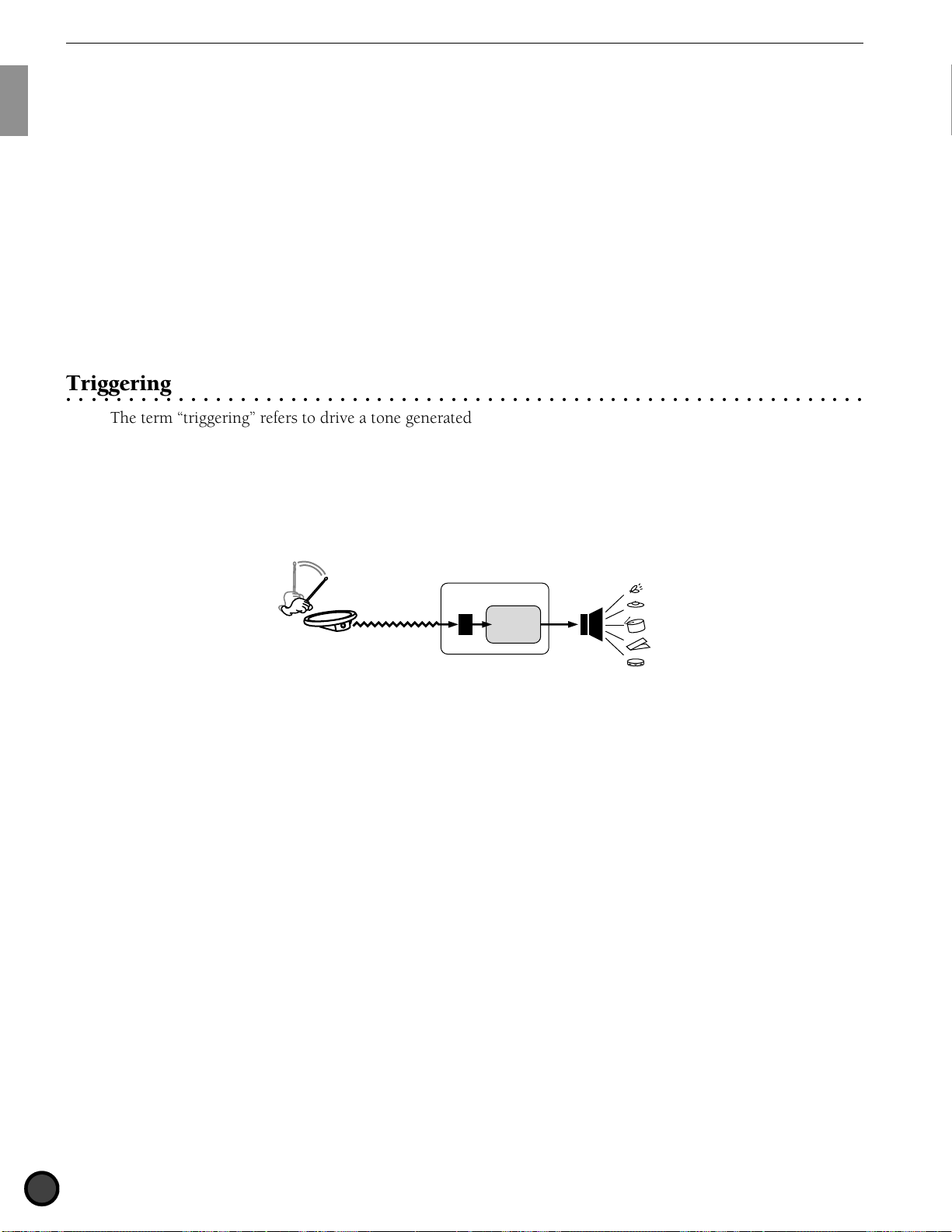
The term “triggering” refers to drive a tone generated from the DTX. The DTX is designed to produce a
trigger signal when a pad or a drum with a trigger sensor connected to the DTX is hit. By assigning up to 5
types of voices of your preference you can produce them at one time by triggering a single signal from a drum
pad. This can be used to perform various effects.
DTX
Tone
generator
20
Page 25
Getting Started
TRIGGER
Modes of the DTX
○○○○○○○○○○○○○○○○○○○○○○○○○○○○○○○○○○○○○○○○○○○○○○○○○○○○○○○○○○○○○○○○○
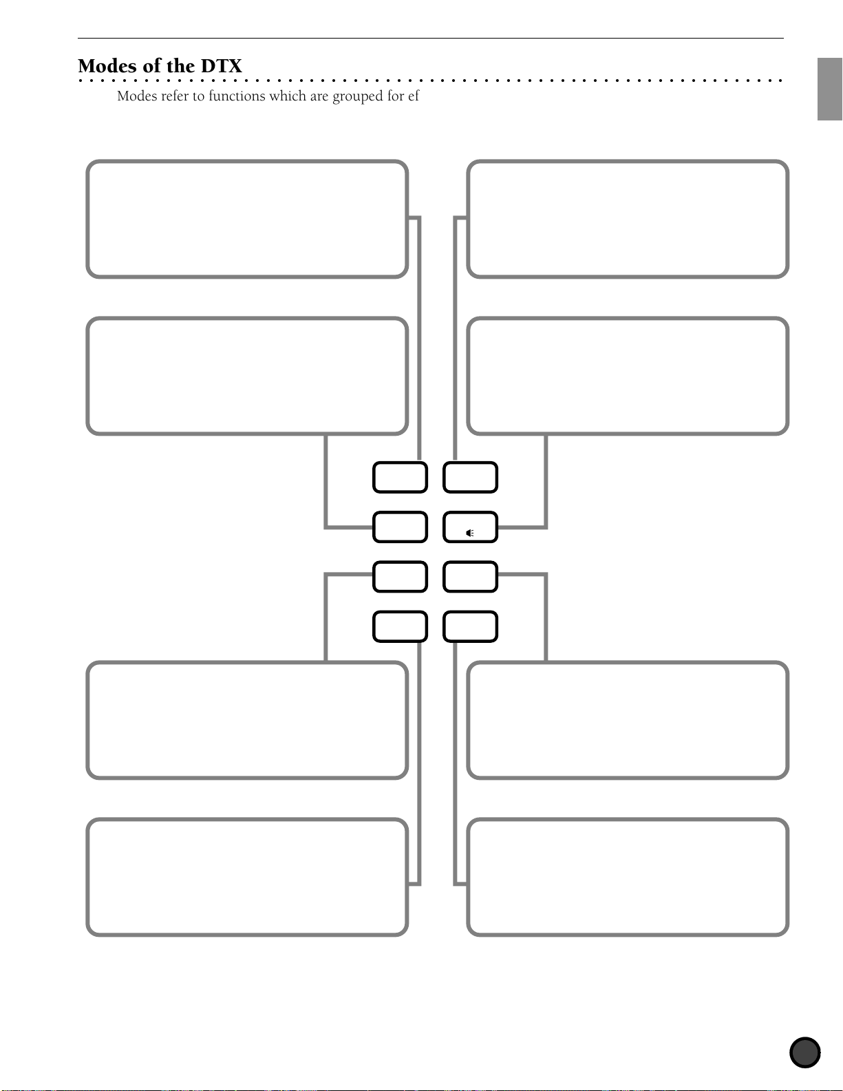
Modes refer to functions which are grouped for efficient operation. The following 8 types of modes are
available.
Drum Kit Play mode (P.30): To select and
play a drum kit.
Chain Play mode (P.63): To play a preset
chain (drum kits or patterns set in a specific
order).
Chain Edit mode (P.65): To create or edit a
chain.
DRUM
KIT
CHAIN
SONG
Drum Kit Trigger Edit mode (P.32): To edit
trigger input levels such as sensitivity.
Drum Kit Voice Edit mode (P.50): To edit
various drum and percussion sound settings.
TRIGGER
VOICE
UTILITY
PATTERN
Song Play mode (P.93): To select and play a
song.
Song Record mode (P.99): To record a song.
Song Job mode (P.107): To edit a song.
Pattern Play mode (P.71): To select and play
a pattern.
Pattern Record mode (P.80): To record a
pattern.
Pattern Job mode (P.88): To edit a pattern.
STORE
Utility mode (P.112): To change the settings
of the entire system such as MIDI, reverb,
equalizer, sequencer and multi-timbre tone
generators.
Store mode (P.69): To store the drum kit or
chain settings.
21
Page 26
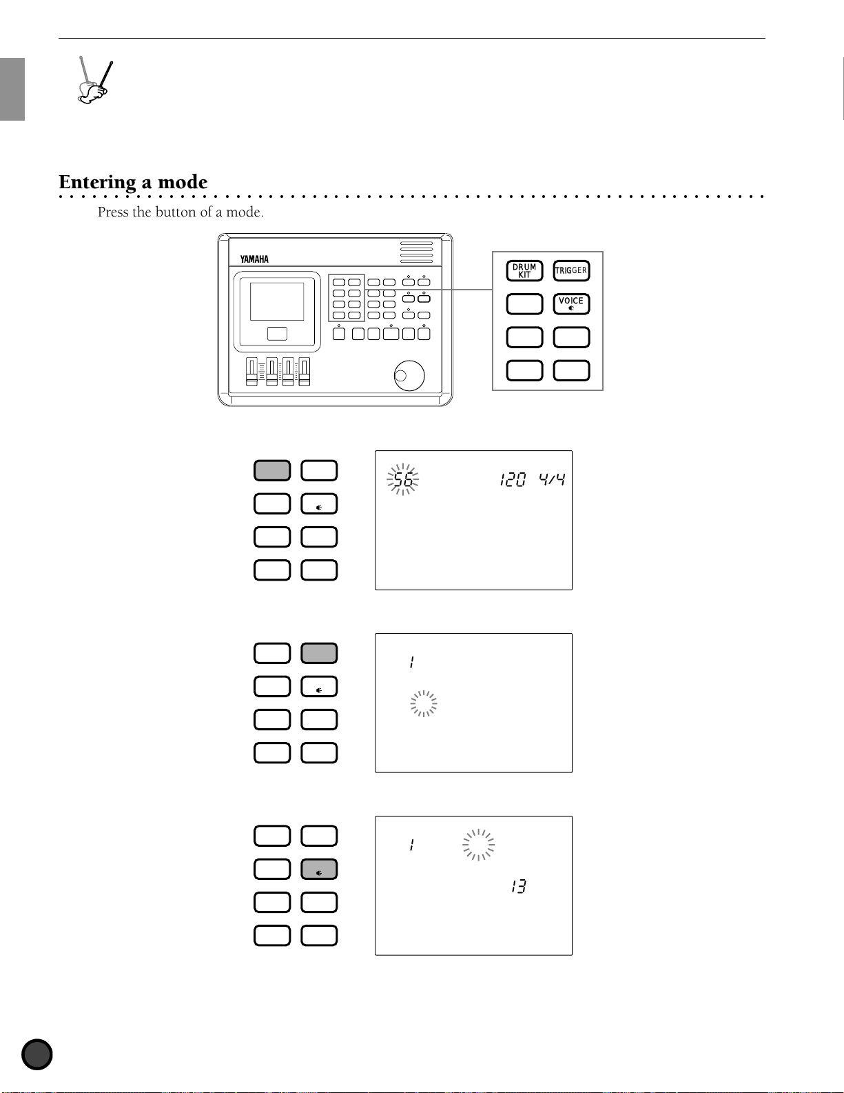
Getting Started
TRIGGER
TTERN
X
T
Y
D
A
M
A
H
A
D
R
E
L
U
D
O
M
U
M
T
R
G
I
Basic Operation
R
E
G
The following describes the basic operation.
Entering a mode
○○○○○○○○○○○○○○○○○○○○○○○○○○○○○○○○○○○○○○○○○○○○○○○○○○○○○○○○○○○○○○○○○
Press the button of a mode.
■Drum Kit Play mode: Press the DRUM KIT button.
DRUM
KIT
CHAIN
SONG
PATTERN
TRIGGER
VOICE
UTILITY
STORE
DRUM KIT
GM std 1
■Drum Kit Trigger Edit mode: Press the TRIGGER button.
DRUM
CHAIN
KIT
TRIGGER
Kit Name
VOICE
GM std 1
SONG
PATTERN
UTILITY
STORE
MISC.
CYMBAL
SNARE
KICK
DRUM
KIT
CHAIN
SONG
PATTERN
TEMPO BEAT
TRIGGER
VOICE
UTILITY
STORE
■Drum Kit Voice Edit mode: Press the VOICE button.
DRUM
CHAIN
SONG
PATTERN
22
KIT
TRIGGER
VOICE
UTILITY
STORE
VCE P 52
P SurdoM
MISC.
CYMBAL
SNARE
KICK
Page 27
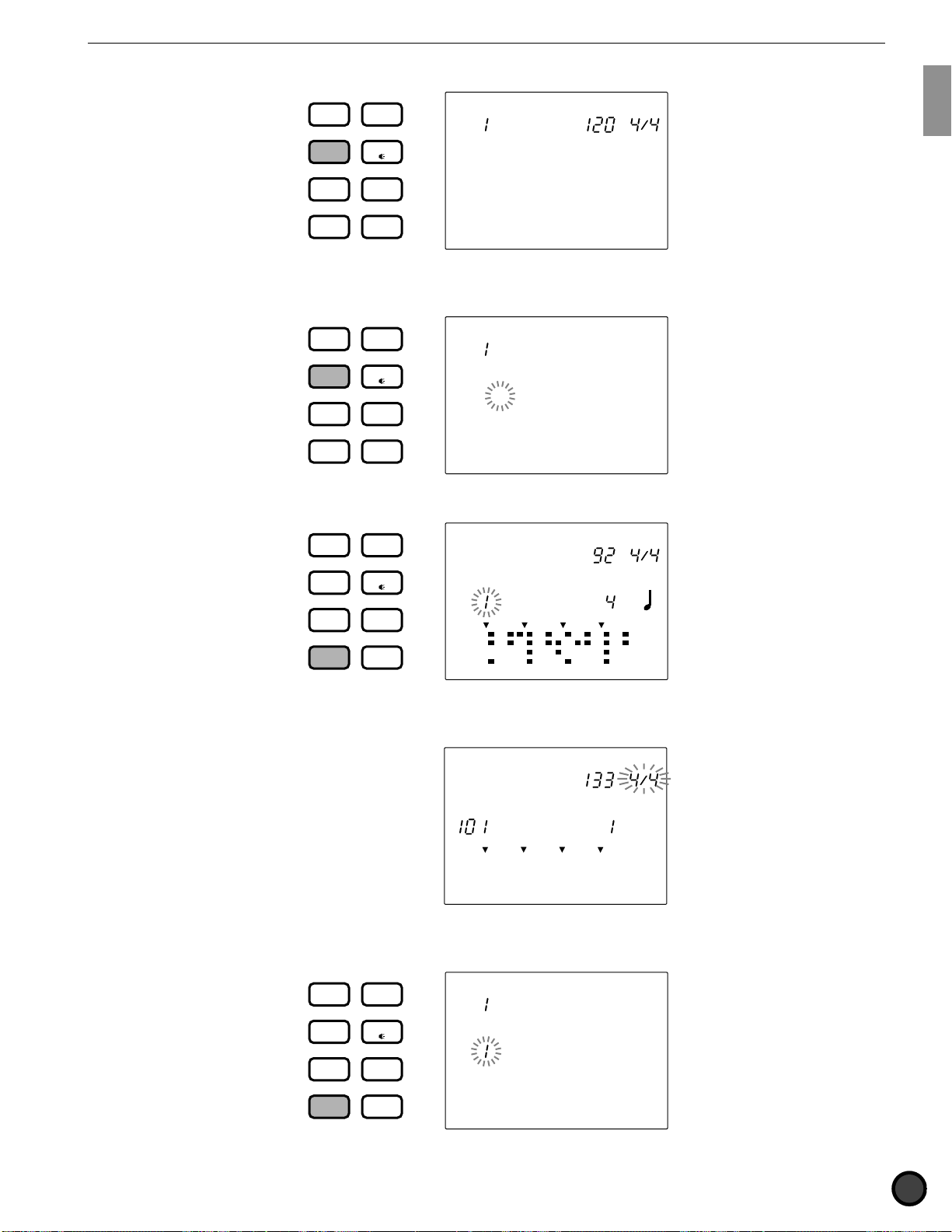
■Chain Play mode: Press the CHAIN button.
Getting Started
DRUM
KIT
CHAIN
SONG
PATTERN
TRIGGER
VOICE
UTILITY
STORE
CHAIN
Chain 1
TEMPO BEAT
■Chain Edit mode: Press the CHAIN button twice or press the CHAIN button once while in Chain Play
mode.
DRUM
CHAIN
KIT
TRIGGER
Name =
VOICE
Chain 1
KIT
UTILITY
STORE
TRIGGER
MISC.
CYMBAL
SNARE
KICK
TEMPO BEAT
SONG
PATTERN
■Pattern Play mode: Press the PATTERN button.
DRUM
CHAIN
VOICE
PATTERN
MEASURE
CLICK
RP Hop
details.
UTILITY
STORE
MISC.
CYMBAL
SNARE
KICK
MAIN A
TEMPO BEAT
SONG
PATTERN
■Pattern Record mode: Enter this mode by taking several steps in Pattern Play mode. Refer to P.80 for
Realtime
PATTERN
REC Mode
MISC.
CYMBAL
SNARE
KICK
■Pattern Job mode: To enter this mode, press the PATTERN button twice or press the PATTERN button
once while in Pattern Play mode.
DRUM
CHAIN
KIT
TRIGGER
VOICE
Copy Pat
PATTERN
MEASURE QUANT.
OFF
RP Hop
SONG
PATTERN
UTILITY
STORE
MISC.
CYMBAL
SNARE
KICK
MAIN A
23
Page 28
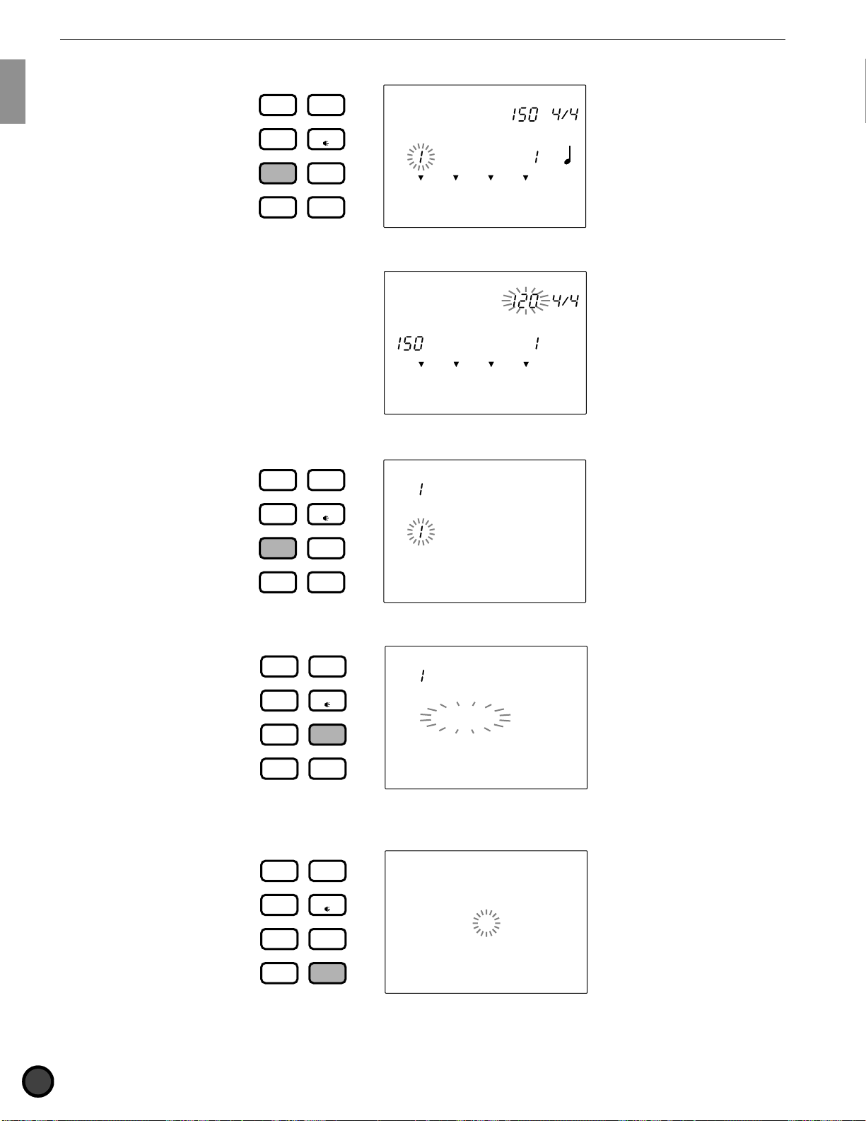
Getting Started
■Song Play mode: Press the SONG button.
DRUM
KIT
CHAIN
TRIGGER
VOICE
SONG
TEMPO BEAT
MEASURE
CLICK
CityDogs
SONG
PATTERN
■Song Record mode: Enter this mode by taking several steps in Song Play mode. Refer to P.99 for details.
UTILITY
STORE
MISC.
CYMBAL
SNARE
KICK
TEMPO BEAT
STEP REC
SONG
REC Mode
MISC.
CYMBAL
SNARE
KICK
■Song Job mode: Press the SONG button twice or press the SONG button once while in Song Play mode.
DRUM
CHAIN
KIT
TRIGGER
VOICE
CopySong
SONG
MEASURE QUANT.
OFF
CityDogs
SONG
PATTERN
UTILITY
STORE
MISC.
CYMBAL
SNARE
KICK
■Utility mode: Press the UTILITY button.
DRUM
CHAIN
KIT
TRIGGER
UTILITY
VOICE
[SYSTEM]
KIT
UTILITY
STORE
TRIGGER
VOICE
MISC.
CYMBAL
SNARE
KICK
DRUM KIT
Store DK
SONG
PATTERN
■Store mode: Press the STORE button while in Drum Kit Play, Trigger Edit or Voice Edit mode to enter
Drum Kit Store mode.
DRUM
CHAIN
to 1
SONG
PATTERN
UTILITY
STORE
MISC.
CYMBAL
SNARE
KICK
24
Page 29

Getting Started
Press the STORE button while in Chain Play mode, Chain mode or Edit mode to enter Chain Store mode.
DRUM
KIT
CHAIN
TRIGGER
VOICE
CHAIN
Store CH
to 1
SONG
PATTERN
Tips on the LCD
○○○○○○○○○○○○○○○○○○○○○○○○○○○○○○○○○○○○○○○○○○○○○○○○○○○○○○○○○○○○○○○○○
The Drum Kit Play mode and Chain Play mode share a common display focus area as shown in the
illustration. The currently selected mode name is displayed on top of the focus area.
UTILITY
STORE
Drum kit or chain
number
MISC.
CYMBAL
SNARE
KICK
Mode Drum kit or chain name
DRUM KIT
PATTERN SONG
CHAIN
MEASURE
MISC.
CYMBAL
SNARE
KICK
MAIN A MAIN B FILL AB FILL BA INTRO ENDING
TEMPO BEAT
QUANT.
INPUT
CLICK
OFF
MUTE
MUTE
MUTE
MUTE
3
The Pattern Play mode and Song Play mode also share the common display focus area.
Style or song name
Mode
PATTERN SONG
MEASURE
CLICK
Style or song
number
MISC.
CYMBAL
SNARE
KICK
Two Play modes can be displayed on the LCD at one time. For example, the Drum Kit Play mode or Chain
Play mode can be displayed at the same time with either the Pattern Play mode or Song Play mode. Other
modes are displayed one at a time.
Drum Kit Play mode display
Example 1 Example 2
DRUM KIT
PATTERN
MISC.
CYMBAL
SNARE
KICK
MAIN A MAIN B FILL AB FILL BA INTRO ENDING
TEMPO BEAT
MEASURE
INPUT
QUANT.
OFF
CLICK
MUTE
MUTE
MUTE
MUTE
3
Chain Play mode display
CHAIN
SONG
MISC.
CYMBAL
SNARE
KICK
MAIN A MAIN B FILL AB FILL BA INTRO ENDING
TEMPO BEAT
MEASURE
INPUT
QUANT.
OFF
CLICK
MUTE
MUTE
MUTE
MUTE
3
Song Play mode displayPattern Play mode display
25
Page 30
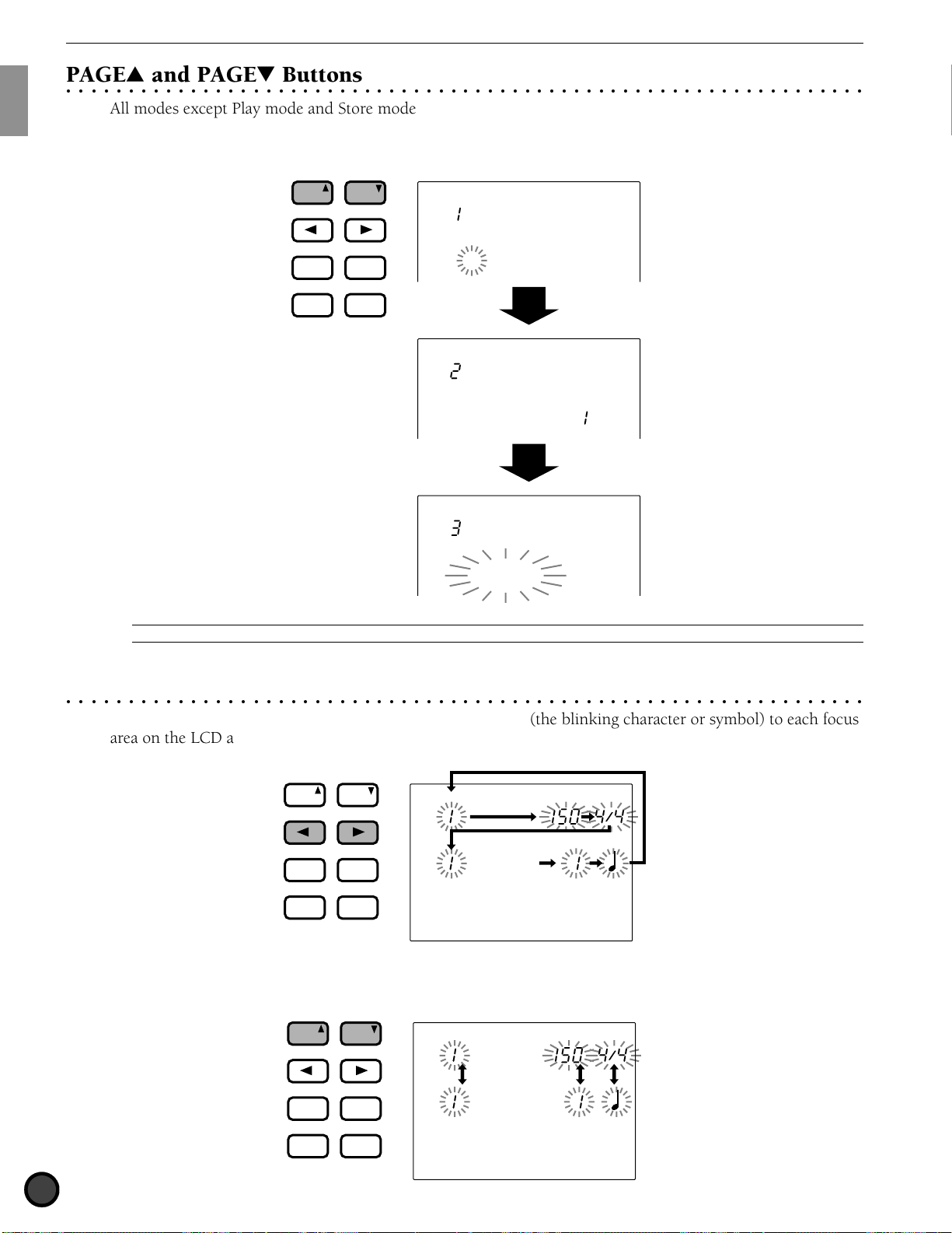
Getting Started
AGE
ERASE
SHIFT
1/YES
1/NO
TEMPO
MAIN B
FILL BA
ENDING
MAIN A
FILL AB
INTRO
AGE
AGE
SHIFT
1/YES
1/NO
TEMPO
AGE
AGE
ERASE
1/YES
1/NO
TEMPO
MAIN B
ENDING
MAIN A
FILL AB
INTRO
AGE
PAGE¡ and PAGE⁄ Buttons
○○○○○○○○○○○○○○○○○○○○○○○○○○○○○○○○○○○○○○○○○○○○○○○○○○○○○○○○○○○○○○○○○
All modes except Play mode and Store mode have multiple display pages. Use the PAGE¡ or PAGE⁄
buttons to select the page. For example, in Chain Edit mode, each time you press the PAGE¡ button the
previous page is selected and each time you press the PAGE⁄ button the next page is selected.
PAGE
ERASE
MAIN A
FILL AB
−
INTRO
TEMPO
1/NO
PAGE
MAIN B
FILL BA
+
1/YES
ENDING
SHIFT
Name =
Chain 1
=DrumKit
num= 1
Edit
recall ?
A
You can also turn the display pages back and forth rotating the Data Scroll Wheel while holding the SHIFT button.
QCursor Buttons
○○○○○○○○○○○○○○○○○○○○○○○○○○○○○○○○○○○○○○○○○○○○○○○○○○○○○○○○○○○○○○○○○
The Q cursor buttons allow you to move the cursor (the blinking character or symbol) to each focus
area on the LCD and the parameters.
PAGE
ERASE
MAIN A
FILL AB
−
INTRO
TEMPO
1/NO
PAGE
MAIN B
FILL BA
+
1/YES
ENDING
SHIFT
DRUM KIT
SONG
CityDogs
MISC.
CYMBAL
SNARE
KICK
TEMPO BEAT
MEASURE
CLICK
Use the PAGE¡ or PAGE⁄ buttons in Play mode to move up and down the display between the modes (e.g.
Drum Kit mode and Pattern mode).
26
PAGE
ERASE
MAIN A
FILL AB
−
INTRO
TEMPO
1/NO
PAGE
MAIN B
FILL BA
+
1/YES
ENDING
SHIFT
DRUM KIT
SONG
CityDogs
MISC.
CYMBAL
SNARE
KICK
TEMPO BEAT
MEASURE
CLICK
Page 31

Getting Started
ERASE
MAIN B
FILL BA
ENDING
MAIN A
FILL AB
INTRO
CLICK
Data Scroll Wheel
○○○○○○○○○○○○○○○○○○○○○○○○○○○○○○○○○○○○○○○○○○○○○○○○○○○○○○○○○○○○○○○○○
The Data Scroll Wheel is used to rapidly change the value of the focus area. Use this to select a drum kit
number or pattern number, or to change the value of various settings.
+1/YES and -1/NO Buttons
○○○○○○○○○○○○○○○○○○○○○○○○○○○○○○○○○○○○○○○○○○○○○○○○○○○○○○○○○○○○○○○○○
The +1/YES and -1/NO buttons change the parameter of the focus area. Use these buttons for fine single-step
selections or adjustments. The parameter will continue to change if you continue to press one of these
buttons. This buttons are also used to answer the “yes/no” question when you are storing data on the DTX.
PAGE
ERASE
MAIN A
FILL AB
−
INTRO
TEMPO
Transport Buttons
○○○○○○○○○○○○○○○○○○○○○○○○○○○○○○○○○○○○○○○○○○○○○○○○○○○○○○○○○○○○○○○○○
1/NO
PAGE
MAIN B
FILL BA
+
1/YES
ENDING
SHIFT
The START/STOP button controls the playback of a pattern or song. The RECORD button puts the DTX into
Record-ready mode. The CLICK button is used to switch the metronome ON and OFF. Refer to P.74, 76,
81, for details.
CLICK
Initializing Process
○○○○○○○○○○○○○○○○○○○○○○○○○○○○○○○○○○○○○○○○○○○○○○○○○○○○○○○○○○○○○○○○○
Problems due to program conflict may occur when internal settings have been changed while you are using
the DTX. It is possible to initialize your DTX if you need to set all of the settings back to factory preset
conditions in one procedure for this reason or other.
C
Once the initialization is executed, the factory preset settings will replace the current contents. Please take precautions to avoid losing your
important data. It is also recommended to store the settings you need to save in advance to external devices such as the Yamaha MIDI Data Filer
(MDF2). (See P.199)
The following changes will occur when the initialization is executed.
● The contents of the preset drum kit will be copied to the user drum kit.
● All of the chain data will be deleted.
● All of user songs and user patterns will be deleted.
● All of the parameter values that can be changed will be set to their standard values.
Turn the power switch on while holding the DRUMKIT, PAGE ¡, and PAGE ⁄ buttons all at the same time.
27
Page 32

Getting Started
28
Page 33

CHAPTER
2
Feature Reference
This chapter describes the functions of each mode.
Use this as a dictionary to look up items or the details and
get to know the various ways to use a function.
Drum Kit Play mode ............................................................................................. (P.30)
Drum Kit Trigger Edit mode ................................................................................ (P.32)
Drum Kit Voice Edit mode ................................................................................... (P.50)
Chain Play mode .................................................................................................. (P.63)
Chain Edit mode .................................................................................................. (P.65)
Store mode ........................................................................................................... (P.69)
Pattern Play mode ................................................................................................ (P.71)
Pattern Record mode ............................................................................................ (P.80)
Pattern Job mode .................................................................................................. (P.88)
Song Play mode .................................................................................................... (P.93)
Song Record mode................................................................................................ (P.99)
Song Job mode...................................................................................................... (P.107)
Utility mode ......................................................................................................... (P.112)
Page 34

Feature Reference — Drum Kit Play Mode
ERASE
MAIN B
FILL BA
ENDING
MAIN A
FILL AB
INTRO
X
T
Y
D
A
M
A
H
A
D
R
E
L
U
D
O
M
U
M
T
R
G
I
Drum Kit Play Mode
R
E
G
This mode enables you to play the DTX drum voices from connected pads and triggers. You can choose
from 64 drum kits.
Entering Drum Kit Play Mode
○○○○○○○○○○○○○○○○○○○○○○○○○○○○○○○○○○○○○○○○○○○○○○○○○○○○○○○○○○○○○○○○○
Press the DRUM KIT button.
DRUM
CHAIN
SONG
PATTERN
A
The Drum Kit Play mode is displayed in the same format as the Pattern Play mode (or Song Play mode).
Selecting a Drum Kit
○○○○○○○○○○○○○○○○○○○○○○○○○○○○○○○○○○○○○○○○○○○○○○○○○○○○○○○○○○○○○○○○○
KIT
TRIGGER
VOICE
UTILITY
STORE
DRUM KIT
Acoustic
PATTERN
MISC.
CYMBAL
SNARE
KICK
TEMPO BEAT
MEASURE
CLICK
! Use the Q cursor buttons to select the drum kit number.
Drum kit nameDrum kit number
PAGE
ERASE
MAIN A
FILL AB
−
1/NO
INTRO
TEMPO
PAGE
MAIN B
FILL BA
+
1/YES
ENDING
SHIFT
DRUM KIT
Acoustic
PATTERN
MISC.
CYMBAL
SNARE
KICK
TEMPO BEAT
MEASURE
CLICK
A
The drum kit number is automatically selected and blinks when you enter Drum Kit Play mode.
30
Page 35

Feature Reference — Drum Kit Play Mode
CLICK
ACCOMP
AUX IN
MIN
MAX
MASTER VOL.
+
CLICKCLICK
KICK/MISC.
ACCOMPACCOMP
SNARE/CYMBAL
AUX INAUX IN
MIN
MIN
MAX
MAX
MASTER VOL.
MASTER VOL.
PAGE AGE
ERASE
SHIFTSHIFT
+
1/YES
−
1/NO1/NO
TEMPOTEMPO
MAIN B
FILL BA
ENDING
MAIN A
FILL AB
INTRO
PAGE AGE
" Rotate the Data Scroll Wheel to choose the drum kit number you want to use. The drum kit number is
also displayed on the LED.
DRUM KIT
TEMPO BEAT
Rock 1
PATTERN
MISC.
CYMBAL
SNARE
KICK
A
You can also change the drum kit number using the +1/YES and -1/NO buttons.
Drum Kit Numbers
User drum kit: 1 to 32
Preset drum kit: 33 to 64
Adjusting the Volume
Use the MASTER volume slider to control the volume of the entire drum kit.
MEASURE
CLICK
MAX
MIN
MASTER VOL.
AUX IN
ACCOMP
SNARE/CYMBAL
CLICK
KICK/MISC.
Individually Adjusting the Volume of Snare and Kick
The volume of the snare and kick can be adjusted independently from other voices.
Move the ACCOMP (SNARE/CYMBAL) volume slider or CLICK (KICK/MISC.) volume slider while holding
SHIFT to adjust the volume of the SNARE voice or KICK voice separately from other voices. This is very
handy at live performances where you can directly control the volume of SNARE, KICK.
A
These volume sliders are originally programmed to function as volume adjustment sliders for an accompaniment part of a pattern (ACCOMP) or
metronome click (CLICK) when the SHIFT button is not pressed. You can change the slider assignment between ACCOMP and SNARE, CLICK and
KICK by changing the parameters in Slider Mode on the 5th page (P.116) in Utility mode. This enables you to use these volume sliders to directly
control the volume of the SNARE and KICK.
A
When playing the pads to a pattern or song, you can balance the volume of the drum voices you are triggering with the pads and the pattern or
song, as well as adjust the volume of each part of the accompaniment or rhythm independently. Refer to P.75 for details.
31
Page 36

Feature Reference — Drum Kit Trigger Edit Mode
X
T
Y
D
A
M
A
H
A
D
R
E
L
U
D
O
M
U
M
T
R
G
I
Drum Kit Trigger Edit Mode
R
E
G
This mode contains various settings to adjust the sensitivity or velocity of the inputs from pads and
triggers or assigning drum and percussion sounds to each pad (input).
You can create a new drum kit from scratch or by modifying preset drum kits or existing user drum kits.
These new drum kits can be stored in the user drum kit area (No. 1 to 32).
A
No. 1 to 29 include drum kits entered in advance. To edit the drum kit for these numbers, it is recommended to copy a user kit between No. 30
to 32 and use it at a later stage. If you have written over No. 1 to 29 , turn the power on while holding down the DRUM KIT, PAGE up and PAGE down
keys at the same time to reset it to its original factory settings. When you do so, all the data will be erased. Save the data you have edited to an
external device such as the Yamaha MIDI Data Filer MDF2 before you reset.
A
You cannot edit a preset drum kit. The changes made to the preset drum kit are temporary. If you want to keep the edited data, select a user
drum kit and save the changes to the user drum kit.
A
Use the blank chart provided at the end of this manual (P.166) to memo the editing contents of the user drum kit.
Editing Procedures
! Choose the drum kit you want to edit in Drum Kit Play mode.
" Enter Drum Kit Trigger Edit mode.
# Name the drum kit if necessary.
$ Turn the page and set the necessary parameters.
A
It is necessary to choose the input jack number (between 1 and 12) before setting the parameter on the 2nd to 18th and 26th pages in this
mode.
% Enter Store mode to store the drum kit to any one of the user drum kit numbers 1 through 32.
Entering the Drum Kit Trigger Edit Mode
○○○○○○○○○○○○○○○○○○○○○○○○○○○○○○○○○○○○○○○○○○○○○○○○○○○○○○○○○○○○○○○○○
Press the TRIGGER button.
DRUM
CHAIN
KIT
TRIGGER
Kit Name
VOICE
GM std 1
SONG
PATTERN
A
Choose the drum kit you want to edit in Drum Kit Play mode before entering this mode. The LED display will show the drum kit number you
have chosen even after you have entered Drum Kit Trigger Edit mode.
A
When the “JumpRcnt (jump to recent page)” parameter on the 7th page in Utility mode is “on”, the DTX will display the page you selected the
last time you edited. Your DTX will display the 1st page when the “JumpRcnt (jump to recent page)” parameter is “off”. See P.116 for details
regarding the “JumpRcnt (jump to recent page)” parameter.
UTILITY
STORE
MISC.
CYMBAL
SNARE
KICK
32
Page 37

Feature Reference — Drum Kit Trigger Edit Mode
Drum Kit Trigger Edit Mode (Page structure and operation)
○○○○○○○○○○○○○○○○○○○○○○○○○○○○○○○○○○○○○○○○○○○○○○○○○○○○○○○○○○○○○○○○○
The Drum Kit Trigger Edit modes consists of 31 display pages of various functions as the drum kit trigger
modules. However, by setting the Edit mode on the 2nd page in Utility mode to “easy”, some of the pages
which are seldomly used will not appear. Change the Edit mode to "advance" to display all 31 pages.
A
The following page shows the list of the 28 display pages. The display pages with asterisks (*) will not appear when the Edit mode in Utility
mode is set to “easy”.
Function name
Page number
Parameter
Input level
Output MIDI
velocity
Hi-hat control
Level
Kit Name
GM std 1
MISC.
CYMBAL
SNARE
KICK
! Select the page using the PAGE¡ or PAGE⁄ buttons.
A
Jump some of the display pages by pressing the DRUM KIT or TRIGGER button while holding SHIFT.
" Select the parameter using the Q cursor buttons.
# Select the input jack number for each of the input numbers 1 to 12. It is necessary to choose the input
jack number before changing the parameters for the 2nd through 18th and the 30th pages. As a short cut,
set the Learn mode on the 4th page in Utility mode to “always”. The input jack number will automatically
be selected by playing a pad connected to the appropriate input (P.115).
$ Set the value by rotating the Data Scroll Wheel or using the +1/YES and -1/NO buttons.
A
In this mode, the input level and the output velocity of the pad you play will appear next to the MISC. and CYMBAL, respectively, as a kind of
VU meter. The Hi-hat control level will also appear on the kick bar chart. This is convenient in editing the sensitivity or velocity.
A
Once you have edited in this mode, a small dot lights on the lower right-hand corner of the drum kit number displayed on the LED to indicate
that the edit results have not been stored. Refer to P.69 on how to store your edit. The dot disappears when you go to Drum Kit Play mode or Chain
mode during an edit to select a different drum kit. The edited settings will return back to the default settings, but you can recall the edited data using
the Recall function (P.49).
Indicates you have not saved
the edited settings.
33
Page 38

Feature Reference — Drum Kit Trigger Edit Mode
Functions of Each Display Page
○○○○○○○○○○○○○○○○○○○○○○○○○○○○○○○○○○○○○○○○○○○○○○○○○○○○○○○○○○○○○○○○
1 Kit Name (drum kit name) ..................................................................................... (P.35)
2 PAD Type (pad type).............................................................................................. (P.35)
3 Auto Set .................................................................................................................. (P.36)
4 PAD Gain................................................................................................................ (P.36)
5 LevelRng (level range) ............................................................................................ (P.37)
6 VelRange (velocity range)....................................................................................... (P.37)
7 VelCurve (velocity curve)....................................................................................... (P.38)
8 Self Rej (self rejection) ........................................................................................... (P.39)
9 Reject (rejection) .................................................................................................... (P.39)
10 Spec Rej (specific rejection) ................................................................................... (P.40)
11 Note= (note numbers 1 to 5) .................................................................................. (P.40)
*12 Note= (gate time) ................................................................................................... (P.42)
*13 Note= (MIDI channel) ............................................................................................ (P.42)
*14 Key On.................................................................................................................... (P.43)
*15 velXFade (velocity cross fade)................................................................................ (P.44)
*16 RIMKeyOn .............................................................................................................. (P.44)
*17 RIM Vel (RIM velocity) .......................................................................................... (P.45)
*18 PAD Func (pad function) ....................................................................................... (P.45)
*19 FS Func (FS function) ............................................................................................ (P.46)
*20 FS MIDI (FS MIDI channel) ................................................................................... (P.47)
*21 FS HHcls (FS hi-hat control) .................................................................................. (P.47)
*22 FC Func (hi-hat control function) .......................................................................... (P.47)
*23 FC MIDI (hi-hat control channel) .......................................................................... (P.47)
*24 FC Sens (hi-hat control sensitivity) ....................................................................... (P.48)
25 HH Ctrl (FS hi-hat control) .................................................................................... (P.48)
*26 In 9 to 10 (input 9 to 10) ....................................................................................... (P.48)
*27 In 11 to 12 (input 11 to 12) ................................................................................... (P.48)
28 Copy INP (copy input) ........................................................................................... (P.48)
29 Copy TRG (copy trigger)........................................................................................ (P.49)
30 Edit (edit recall) ..................................................................................................... (P.49)
*31 SetChord= (setting the note number by chord) ..................................................... (P.49)
A
The "26 In 9 to 10 (input 9 to 10)" and "27 In 11 to 12 (input 11 to 12)" are additional features of DTX version 2.0. Please refer to the System
Upgrade Information Guide (included in this package) for details.
34
Page 39

Feature Reference — Drum Kit Trigger Edit Mode
1 Kit Name (drum kit name)
Use up to 8 letters to name your original user
drum kit.
! Use the Q cursor buttons to go to the
first letter of the drum kit name and choose the
necessary alphabet, number, or symbol by
rotating the Data Scroll Wheel or using the +1/
YES and -1/NO buttons.
" Move to the right and choose the necessary letter.
# Repeat steps ! and " above and name your
drum kit using a maximum of 8 letters.
Kit Name
GM std 1
MISC.
CYMBAL
SNARE
KICK
The available letters to choose from are:
2 PAD Type
Set the type of the pad or drum connected to
each input jack. To ensure stable performance,
be sure to select the proper pad type. Pad1 has
the quickest response and kick2 has the longest
response.
! Move the cursor to the INPUT focus area
and rotate the Data Scroll Wheel or use the
+1/YES and -1/NO buttons to select the
input jack number.
As a short cut, set the Learn mode on the 4th
page in Utility mode to ALWAYS. The input
jack number will automatically change to the
connected input jack by playing a pad,
(P.115).
" Move the cursor to the PAD TYPE parameter
and rotate the Data Scroll Wheel or use the
+1/YES and -1/NO buttons to select the pad
type that suits the pad or drum connected to
the input jack number.
# Repeat steps ! and " to set the proper pad
type for each input jack number.
(Space)
PAD Type
INPUT
= pad2
MISC.
CYMBAL
SNARE
KICK
Settings:
The following parameters are available for input
numbers 1 to 12.
pad1/pad2: Select this when you have connected an
optional pad. Choose the response time for each
connected pad. Pad2 responds faster than pad1.
snare: Select this when you have connected the
Yamaha DT10 to a snare.
hi tom: Select this when you have connected the
Yamaha DT10 or DT20 to a hi tom (smaller tom).
lo tom: Select this when you have connected the
Yamaha DT10 or DT20 to a low tom (larger tom).
kick1/kick2: Select this when you have connected the
Yamaha DT 10 to the kick (bass drum). Kick2
responds faster than kick1.DT10 and DT20 are drum
trigger sensors. Refer to P.11.
35
Page 40

Feature Reference — Drum Kit Trigger Edit Mode
3 Auto Set
This automatically sets the input gain
(sensitivity) of each input jack number.
A
The appropriate input gains are preset as a setting
example so that you can start to play without any input
adjustment. However, you are required to adjust the input gain
for each pad either here or in the next PAD gain section for your
own drum settings.
! Move the cursor to the INPUT focus area
and rotate the Data Scroll Wheel or use the
+1/YES and -1/NO buttons to choose the
input jack number.
You can also enable the Learn mode (P.115)
to automatically select the input jack number
by hitting each pad or drum, then select the
input gain.
" Move the cursor to the focus area and press
the +1/YES button. The display will change
to “HIT2ff”.
4 PAD Gain
This manually sets the input gain (sensitivity) of
each input jack number.
! Move the cursor to INPUT and rotate the
Data Scroll Wheel or use the +1/YES and -1/
NO buttons to choose the input jack
number.
You can also enable the Learn mode (P.115)
to automatically select the input jack number
by hitting each pad or drum, then select the
input gain.
" Move the cursor to the gain focus area and
rotate the Data Scroll Wheel or use the +1/
YES and -1/NO buttons to set the Gain. Play
the pad or drum connected to the selected
input jack number hard (ff=fortissimo) and
adjust the Gain level to approximately 90%
of the Input level.
# Repeat steps ! and " and set the input
Gain for each input jack number.
Auto Set
INPUT
= Off
MISC.
CYMBAL
SNARE
KICK
" Slowly beat the pad or drum connected to
the input jack hard (ff=fortissimo) twice.
The first beat changes the display to HIT1 ff
and the second beat changes the display to
“Off” quitting the automatic setting.
# Repeat steps !, ", and # to set the input
gain for each input jack number.
PAD Gain
Gain
Input level
B
The input gain can be set faster and more efficiently if
you use the Auto Set first to automatically set the levels and
then make fine adjustments here.
Settings:
The following parameters can be set for input numbers
1 to 12.
Gain: 0 to 63.
A
The Input level display here is operated differently from
other displays and cannot be set by moving the cursor to the
focus area. Set the Input level by following step 2 above.
=32(00%)
MISC.
CYMBAL
SNARE
KICK
INPUT
36
Page 41

Feature Reference — Drum Kit Trigger Edit Mode
MISC.
SNARE
KICK
CYMBAL
INPUT
VelRange
32to127
Minimum
velocity
Maximum
velocity
5 LevelRng (level range)
Set the Maximum and Minimum input levels of
each input jack number. The levels are
determined in proportion to the value set here.
A
Refer to P.38 for further details regarding the relation
between input level and velocity.
! Move the cursor to INPUT and Rotate the
Data Scroll Wheel or use the +1/YES and -1/
NO buttons to choose the input jack
number.
You can also enable the Learn mode (P.115)
to automatically select the input jack number
by hitting each pad or drum.
" Move the cursor to the Maximum or
Minimum level focus area and rotate the
Data Scroll Wheel or use the +1/YES and -1/
NO buttons to set the level.
# Repeat steps ! and " to set the Maximum
and Minimum levels for each input jack
number.
6 VelRange (velocity range)
Set the Maximum and Minimum velocity of
each input jack number. This responds to the
maximum and minimum input levels set on the
5th page and delivers each sound within the
velocity range set in this step.
A
Refer to P.38 for further details regarding the relation
between input level and velocity.
! Move the cursor to the INPUT focus area
and rotate the Data Scroll Wheel or use the
+1/YES and -1/NO buttons to choose the
input jack number.
You can also enable the Learn mode (P.115)
to automatically select the input jack number
by hitting each pad or drum.
" Move the cursor to the Minimum Velocity or
Maximum Velocity focus areas and rotate the
Data Scroll Wheel or use the +1/YES and -1/
NO buttons to set the velocity.
# Repeat steps ! and " to set the Maximum
and Minimum Velocity levels for each input
jack number.
LevelRng
Minimum
level
Maximum
level
A
No sound will be produced if the input signal is below
the minimum level. If the input signal is above the maximum
level, the sound produced will be at the maximum velocity set
on the Velocity Range display page (the 6th page of this
mode).
Settings:
The following parameters can be set for input numbers
1 to 12.
Minimum level: 0 to 98
Maximum level: 1 to 99
10%to99%
MISC.
CYMBAL
SNARE
KICK
INPUT
Settings:
The following parameters can be set for input numbers
1 to 12.
Minimum velocity: 1 to 126
Maximum velocity: 2 to 127
37
Page 42

Feature Reference — Drum Kit Trigger Edit Mode
Velocity
Input level
Velocity
Input level
7 VelCurve (velocity curve)
Set the velocity curve for each input jack
number. This velocity curve defines the relation
between the level range set on the 5th page and
the velocity range set on the 6th page.
! Move the cursor to the INPUT focus area
and rotate the Data Scroll Wheel or use the
+1/YES and -1/NO buttons to choose the
input jack number.
You can also enable the Learn mode (P.115)
to automatically select the input jack number
by hitting each pad or drum.
" Move the cursor to the Velocity Curve focus
area and rotate the Data Scroll Wheel or use
the +1/YES and -1/NO buttons to select the
type.
# Repeat steps ! and " to set the Velocity
Curve of each input jack number.
VelCurve
INPUT
= normal
MISC.
CYMBAL
SNARE
KICK
VelCurve: loud 1
VelCurve: loud 2
Relationship between input level and velocity.
Case 1
This figure shows that the velocity will be output at
an input level range of 12% to 99%. The velocity
value is 001 when the input level is 12% and 127
when the input level is 99%. (In this case, the
velocity range is 1 to 127.)
Velocity
127
Settings:
The following velocity curves can be set for input numbers
1 to 12.
VelCurve: normal
Velocity
Input level
VelCurve: hard 1
Velocity
Input level
VelCurve: hard 2
Velocity
001
Input level
99%12%
Case 2
This figure shows that the velocity range is set
between 064 and 127, and the velocity triggers at
an input level of 50% to 99%. The velocity value
is 064 when the input level is 50% and 127 when
the input level is 99%. No sound will be produced
when the input level is between 0% and 49%.
Velocity
127
064
001
0〜 49%
No sound
Input level
99%50%
38
Input level
Page 43

Feature Reference — Drum Kit Trigger Edit Mode
8 Self Rej (self rejection)
This function prevents double triggering. When
2 sounds have been played at the same time, the
second sounds will be automatically muted for a
certain length of time. The larger the value the
longer the time. Set the length for each input
jack number.
! Move the cursor to the INPUT focus area
and rotate the Data Scroll Wheel or use the
+1/YES and -1/NO buttons to choose the
input jack number.
You can also enable the Learn mode (P.115)
to automatically select the input jack number
by hitting each pad or drum.
" Move the cursor to the 8 Self Rej (self
rejection) focus area and rotate the Data
Scroll Wheel or use the +1/YES and -1/NO
buttons to set the level.
# Repeat steps ! and " to set the time length
for each input jack number.
9 Reject (rejection)
This function prevents cross talk (mixed
sounds) and double triggering among the pads
or drums connected to other input jacks. When
a sound is triggered shortly after another, the
voice will not be delivered if the input level is
lower than the level set here. Set the level for
each input jack number.
! Move the cursor to the INPUT focus area
and rotate the Data Scroll Wheel or use the
+1/YES and -1/NO buttons to choose the
input jack number.
You can also enable the Learn mode (P.115)
to automatically select the input jack number
by hitting each pad or drum.
" Move the cursor to the 9 Reject (rejection)
focus area and rotate the Data Scroll Wheel
or use the +1/YES and -1/NO buttons to set
the level.
# Repeat steps ! and " to set the level for
each input jack number.
Self Rej
INPUT
= 0
MISC.
CYMBAL
SNARE
KICK
Settings:
The following parameters can be set for input numbers
1 to 12.
0 (self rejection function disabled) to 9
Reject
INPUT
= 0
MISC.
CYMBAL
SNARE
KICK
Settings:
The following parameters can be set for input jack
numbers 1 to 12.
0 (rejection function disabled) to 9
39
Page 44

Feature Reference — Drum Kit Trigger Edit Mode
10 Spec Rej (specific rejection)
This function prevents cross talk (mixed
sounds) among the pads or drums connected to
specific input jacks. When a sound is triggered
shortly after a specific sound, the sound will not
be delivered if the level is lower than the level
set here. Set the level for each input jack
number.
! Move the cursor to the INPUT focus area
and rotate the Data Scroll Wheel or use the
+1/YES and -1/NO buttons to choose the
input jack number.
You can also enable the Learn mode (P.115)
to automatically select the input jack number
by hitting each pad or drum.
" Move the cursor to the specific input focus
area and rotate the Data Scroll Wheel or use
the +1/YES and -1/NO buttons to select the
input jack number.
# Move the cursor to the level focus area and
rotate the Data Scroll Wheel or use the +1/
YES and -1/NO buttons to set the level.
11 Note= (note numbers settings)
This function assigns note numbers to each
input. You can assign up to 7 MIDI note
numbers to each input jack. When a trigger
signal is sent to the input jack, the MIDI note
number assigned to that input jack is sent to the
internal tone generator, which delivers the
sound assigned to that number. This enables
you to play 1 pad and deliver multiple (up to 5)
drum sounds. The order of the 5 drum sounds
to sound can be designated.
By setting the Key On Mode (P.43), the sounds
can be delivered simultaneously, or one by one.
This feature can be applied to a wide range of
ideas and enhance the efficiency of your
performance.
The MIDI note number can also be transmitted
from the MIDI OUT jack on the rear panel of
the DTX to an external device. This means you
can play a pad and control an external MIDI
tone generator or sequencer.
Various drum and percussion sounds can be
assigned to each note number in Drum Kit
Voice Edit mode (P.50). Refer to P.41 for
further information on note numbers.
$ Repeat steps !, ", and # to select and set
the level of each input jack number.
Spec Rej
Specific input
focus area
Level focus area
Settings:
The following parameters can be set for input jack numbers
1 to 12.
Specific input: 1 to 12
0 (rejection function disabled) to 9
from 1=0
MISC.
CYMBAL
SNARE
KICK
INPUT
!
Move the cursor to the INPUT focus area and
rotate the Data Scroll Wheel or use the +1/YES
and -1/NO buttons to choose the input jack
number.
You can also enable the Learn mode (P.115) to
automatically select the input jack number by
hitting each pad or drum.
" Move the cursor to the Note=*** focus area and
rotate the Data Scroll Wheel or use the +1/YES
and -1/NO buttons to select the parameter (type)
from the 5 numbers (1st to 5th), mut (mute), and
rim for a MIDI note number.
A
Select mut (mute) when designating the note number for
the sound delivered when the pad is played while holding down
the pad rim switch. The other 5 sounds will be muted when the
pad is played while holding down the rim switch.
A
Select rim to set the note number of the sound delivered
when the rim is played.
A
when or an input number is assigned to a hi-hat
controller (the default setting is input 8), the focus area will
display the following 5 parameters.
Opn:
Delivered when the pad is played with the hi-hat opened
Cls:
Hi-hat closed
FCl:
Foot closed
FOp:
Foot opened
rim:
Pad rim is held
40
Page 45

Feature Reference — Drum Kit Trigger Edit Mode
# Move the cursor to the MIDI note number
focus area and rotate the Data Scroll Wheel
or use the +1/YES and -1/NO buttons to
select the note number of the drum voice.
A
Assign a MIDI note number the drum voice to in Drum
Kit Voice Edit mode (P.50).
A
The right side of the MIDI note number focus area shows
the note name. The MIDI note number corresponds to each
key on the keyboard. You can move the cursor to each focus
area and set the note number using the note name. This is
convenient when you are planning to play a scale on an
external tone generator.
The relationship between note numbers and names.
MIDI defines the note “C” in the center of the keyboard as note
number 60. Yamaha defines the note by putting a number that
symbolizes the octave, and the “C” in the center of the
keyboard is regarded as “C3”.
C3C2C1C0 C4 C5 C6
MIDI
note
number
A
Skip (skp) can be selected when the Key On Mode
on the 14th page of the Key On screen (P.43) is set to
"alter" or "alterMN." This enables you to skip the notes set
in Skip (skp) when you are playing each sound in
sequence by playing the pads.
604836240 728496C7108 127
Using chord names to set the MIDI note number
Press the CHORD button while holding SHIFT to
display the 31th page or SetChord (chord settings).
This display is used to set the chords played by
hitting a pad. By selecting a chord from the 12
roots and 25 types available, a MIDI note number
representing the chord is automatically set to one
of the 1st to 4th notes.
! Move the cursor to the INPUT focus area and
rotate the Data Scroll Wheel or use the +1/YES
and -1/NO buttons to choose the input jack
number.
You can also enable the Learn mode (P.115) to
automatically select the input jack number by
hitting each pad or drum.
" Move the cursor to the ROOT focus area of the
CHORD and rotate the Data Scroll Wheel or
use the +1/YES and -1/NO buttons to choose
the ROOT type.
# Repeat steps ! and " and set the CHORD for
each INPUT number.
$ To go back to the first page of this mode (the
note number settings on the 11th page), press
the PAGE¡ or PAGE⁄ buttons.
$ Repeat steps " and # to assign the other
MIDI note numbers and select the parameter
(type). After you have completed setting the
MIDI note numbers, go to step ! and set
the parameters for the MIDI note numbers of
the other input numbers.
Note
Note=1st
MIDI note
number
Note name
= 36 C 1
MISC.
CYMBAL
SNARE
KICK
Settings:
The following parameters can be set for input numbers 1
to 12.
Note:1st, 2nd, 3rd, 4th, 5th, mut, rim (or Opn, Cls,
FCl, FOp, rim)
MIDI note number: off, 13 to 84.
INPUT
SetChord
INPUT
Root
Type
Settings:
The following parameters can be set for input
numbers 1 to 12.
Root: C, CG, D, DG, E, F, FG, G, GG, A, AG, B
Type: Maj7, Maj, 6th, M7(11), Maj9, add9,
min, min6, min7, m7(a5), mM7, min9, m
add9, 7th, 7(G5), 7(a9), 7th9, 7(G9), 7G(11),
7(a13), 7(13), 7sus4, sus4, dim, aug
A
Refer to the chord type list on P.79 for details of
each chord.
MISC.
CYMBAL
SNARE
KICK
CMaj7
41
Page 46

Feature Reference — Drum Kit Trigger Edit Mode
12 Note= (gate time)
Sets the gate time (length) of the pad you play.
The gate time applies to 5 note numbers at one
time and can be set for each input jack number.
As for input 8 (hi-hat) or an input number
assigned to a hi-hat controller, you can set a
different gate time to ; Open, Cls, FCl, FOp and
rim.
! Move the cursor to the INPUT focus area
and rotate the Data Scroll Wheel or use the
+1/YES and -1/NO buttons to choose the
input jack number.
You can also enable the Learn mode (P.115)
to automatically select the input jack number
by hitting each pad or drum.
" Move the cursor to the Note focus area and
rotate the Data Scroll Wheel or use the +1/
YES and -1/NO buttons to select the 1st
note. The gate time for all 5 notes are set
just by selecting the 1st note.
A
If you select a note other than the 1st, the gate time
focus area will display “--” and you will not be able to set the
gate time.
A
When an input number assigned to a hi-hat controller is
selected (the default setting is input 8), you can select from
Open, Cls, FCl, FOp and rim.
A
When the Key On Mode on the 14th page of the Key On
screen (P.43) is set to anything besides "hold," you can set
different gate times to each of the five notes.
Opn .............. Settings simular to an open hi-hat sound.
Cls ................ Settings simular to a close hi-hat sound.
FCl ............... Settings simular to a closeing hi-hat sound.
FOP .............. Settings simular to an opening hi-hat sound.
13 Note= (MIDI channel)
Sets the 1st to 5th MIDI transmitting channels
to the MIDI note number of each input jack
number. You can set an external device to
trigger a keyboard (normal) voice using the
DTX internal tone generator if you have the
input jack number set to a MIDI note number
that triggers a chord or bass voice in the DTX.
! Move the cursor to the INPUT focus area
and rotate the Data Scroll Wheel or use the
+1/YES and -1/NO buttons to choose the
input jack number.
You can also enable the Learn mode (P.115)
to automatically select the input jack number
by hitting each pad or drum.
" Move the cursor to the Note focus area and
rotate the Data Scroll Wheel or use the +1/
YES and -1/NO buttons to select 1st to 5th
mut (mute) to a MIDI channel.
A
When an input number assigned to a hi-hat controller is
selected (the default setting is input 8), you can select from
Open, Cls, FCl, FOp and rim. Refer to 12 Note=(gate time)for
details.
# Move the cursor to the Channel focus area
and set the MIDI channels.
A
To select the same MIDI channel for all 5 notes, first set
the MIDI channel for the 1st note, then select MIDI channel 1
and repeat this procedure for the rest of the notes. This will
indicate that you will be using the same channel as the 1st.
A
You can also trigger a keyboard voice by designating a
MIDI channel (other than 10 for the drum voice).
42
# Move the cursor to the Gate Time focus area
and rotate the Data Scroll Wheel or use the
+1/YES and -1/NO buttons to set the gate
time.
$ Repeat steps !, ", and # to set the Gate
Time for each input jack number.
Note=1st
Note
INPUT
GT= 3.0s
Gate time
Settings:
The following parameters can be set for input numbers
1 to 12.
Note: 1st, 2nd, 3rd, 4th, 5th, mut, rim or (Opn, Cls,
FCl, FOp)
Gate time: off, 0.0 to 10.0 seconds (settings by 1/10
seconds).
MISC.
CYMBAL
SNARE
KICK
A
Select bas or cho for inputs which trigger a bass or
chord. This indicates that you will be using the same MIDI
channel as a BASS track and CHORD track used to play a
pattern or song, and the keyboard voices to be triggered.
When you have chosen bas or cho, the 1st to 5th note numbers
will change according to the chord progression of the pattern
or song.
$ Repeat steps !, ", and # to set the MIDI
channel for each input jack number.
Note=1st
Note
INPUT
Chan= 10
MIDI channel
Settings:
The following parameters can be set for input numbers
1 to 12.
Note: 1st, 2nd, 3rd, 4th, 5th, mut, rim (or Opn, Cls,
FCl, FOp)
MIDI channels: 1 to 16, cho, bas
MISC.
CYMBAL
SNARE
KICK
Page 47

Feature Reference — Drum Kit Trigger Edit Mode
14 Key On
Sets the key on mode for each input.
The Key on mode defines how multiple notes
(up to of 5) which are set to each INPUT
number should be triggered. There are 5 key
on modes which enable you to trigger all notes
at the same time or in a specific order. This
function is convenient when you want to layer
multiple voices or produce an effect using the
keyboard voice.
! Move the cursor to the INPUT focus area
and rotate the Data Scroll Wheel or use the
+1/YES and -1/NO buttons to choose the
input jack number.
You can also enable the Learn mode (P.115)
to automatically select the input jack number
by hitting each pad or drum.
" Move the cursor to the Key on mode focus
area and rotate the Data Scroll Wheel or use
the +1/YES and -1/NO buttons to select the
key on mode from the following:
# Repeat steps ! and " to set the key on
mode for each input jack number.
Key On
INPUT
= stack
MISC.
CYMBAL
SNARE
KICK
Settings:
The following parameters can be set for input numbers
1 to 12.
Key on mode: stack, alter, stackMN, alterMN, hold
stack ............. Triggers the 1st to 5th notes (P.40)
alter .............. Triggers the 1st to 5th notes one by one
stackMN ....... Triggers the 1st to 5th notes
alterMN ........ Alternately triggers the 1st to 5th notes in
hold .............. Triggers and maintains the 1st to 5th notes
A
(Yamaha TP80S or PCY80S pads) note set by mut (mute) is
enabled and the 1st to 5th notes are disabled. Therefore the
trigger types of stack and alter, stackMN and alterMN become
the same.
A
memory space by excluding overlapping voices when
recording to an external sequencer.
simultaneously.
each time the pad is played.
simultaneously, but truncates the
preceding sound when the pad is played.
order, but truncates the preceding sound
when the pad is played.
simultaneously when the pad is played
once, and stops when the pad is played
again.
When the pad is played while holding the Rim Switch
By using the stackMN or alterMN function you can save
43
Page 48

Feature Reference — Drum Kit Trigger Edit Mode
15 VelXFade (velocity cross-fade)
This function sets the velocity cross-fade for
each input jack number on or off.
When several MIDI note numbers are assigned
on the 11th Note Number page and this
function is on, the softer you play the pad, the
1st note is louder and the last note the smallest.
The same applies to the opposite action: the
harder you play the pad, the last note is louder
and the first note the smallest.
Output velocity
120
100
80
60
40
20
1st
0
0 20406080100120
Case of 1 5th
5th
4th
3rd
2nd
16 RIMKeyOn
This function sets the rim key on mode to
define how the voice is triggered when the rim
of the pad is played. The “single” mode is used
for the usual rim shot voice and the Hold mode
is used to maintain the sound.
! Move the cursor to the INPUT focus area
and rotate the Data Scroll Wheel or use the
+1/YES and -1/NO buttons to choose the
input jack number.
You can also enable the Learn mode (P.115)
to automatically select the input jack number
by hitting each pad or drum.
" Move the cursor to the mode focus area and
rotate the Data Scroll Wheel or use the +1/
YES and -1/NO buttons to select the rim key
on mode from the following 2 modes:
single ............ Normal triggering of a rim shot
hold .............. The first shot maintains the voice and the
second shot stops the voice.
A
This function applies only when the key on mode on the
14th page is set to stack, stackMN, or hold.
A
This function is valid only when more than 2 MIDI note
numbers are assigned to note numbers 1 to 5 on the 11th
display page.
! Move the cursor to the INPUT focus area
and rotate the Data Scroll Wheel or use the
+1/YES and -1/NO buttons to choose the
input jack number.
You can also enable the Learn mode (P.115)
to automatically select the input jack number
by hitting each pad or drum.
" Move the cursor to the VelXFadefocus area
and rotate the Data Scroll Wheel or use the
+1/YES and -1/NO buttons to turn the
function “on”or “off”.
VelXFade
INPUT
= off
MISC.
CYMBAL
SNARE
KICK
withPad ........ When the rim is hit, the sound set to the
Rim and the sound set to the pad will play
at the same time.
# Repeat steps ! and " for each input jack
number.
RIMKeyOn
INPUT
= single
MISC.
CYMBAL
SNARE
KICK
Settings:
The following parameters can be set for input numbers
1 to 8.
RIM Key On mode: single, hold, withPad
Settings:
The following parameters can be set for input numbers
1 to 12.
VelXFade: on, off
44
Page 49

Feature Reference — Drum Kit Trigger Edit Mode
17 RIM Vel (RIM velocity)
This function sets the velocity of the trigger
when the rim of the pad is played. There are 2
types of settings: one where the velocity is
always the same level, and the other where the
velocity changes according to the impact of the
attack.
! Move the cursor to the INPUT focus area
and rotate the Data Scroll Wheel or use the
+1/YES and -1/NO buttons to choose the
input jack number.
You can also enable the Learn mode (P.115)
to automatically select the input jack number
by hitting each pad or drum.
" Move the cursor to the Velocity focus area
and rotate the Data Scroll Wheel or use the
+1/YES and -1/NO buttons to select the
velocity. The settings vary as follows:
mute Hi ....... The velocity changes according to the strength of
the attack on the rim. In the same manner as the
pad velocity, the velocity is automatically
calculated based on the level range, velocity range
and velocity curve on the 5th, 6th, and 7th
display pages. The difference
between“variabl”described below is that pad will
be muted if the DTX receives a trigger lower than
the minimum level set for level range on the 5th
display page. This is convenient when you are
using cymbal pads.
mute Lo ....... The setting is simular to “mute Hi” above, but
enables you to set the velocity at a lower level Use
“mute Hi” when you are using the mute more
than the rim, and “mute Lo” when you are
playing the rim more than using the mute.
variabl ......... The velocity changes according to the strength of
the attack on the rim. In the same manner as the
pad velocity, the velocity is automatically
calculated based on the level range, velocity range
and velocity curve on the 5th, 6th, and 7th
display pages.
18 PAD Func (pad function)
This function sets the function of each pad
connected to INPUT. Besides acting as a regular
drum pad, various pad functions are available.
For example, in Chain mode, you can move a
chain step forward or backward, start or stop a
pattern or song, or assign the pad to act as a
switch for other types of functions.
! Move the cursor to the INPUT focus area
and rotate the Data Scroll Wheel or use the
+1/YES and -1/NO buttons to choose the
input jack number.
You can also enable the Learn mode (P.115)
to automatically select the input jack number
by hitting each pad or drum.
" Move the cursor to the parameter and rotate
the Data Scroll Wheel or use the +1/YES and
-1/NO buttons to select the function. The
following functions are available:
normal .......... The regular setting which triggers the MIDI
signal when the pad is played.
click .............. Turns the click ON or OFF.
inc ................ Selects the next drum kit number in Drum
Kit mode or step in Chain mode.
dec ................ Selects the previous drum kit number in
Drum Kit mode or step in Chain mode.
bypass .......... Cuts the voices of all other pads except the
one selected, ON or OFF.
strtStp .......... Starts or stops the style pattern or song.
pause ............ Pauses the style pattern or song.
do FILL ......... Changes the section to FILL.
MAIN A ........ Changes the section to MAIN A.
fix1 to fix127 .....
The velocity set here remains the same regardless
of the strength of the attack on the rim. The
mute function cannot be used if values are set to
this function. The voice trigger is faster
compared to mute Hi and mute Lo.
# Repeat steps ! and " to set the velocity of
each input jack number.
RIM Vel
INPUT
=mute Hi
MISC.
CYMBAL
SNARE
KICK
Settings:
The following parameters can be set for input numbers
1 to 8.
Rim Vel mode: mute Hi, mute Lo, variabl, fix1 to
fix127.
MAIN B ........ Changes the section to MAIN B.
FILL AB ........ Changes the section to FILL AB.
FILL BA ........ Changes the section to FILL BA.
INTRO .......... Changes the section to INTRO.
ENDING ....... Changes the section to ENDING.
45
Page 50

Feature Reference — Drum Kit Trigger Edit Mode
# Repeat steps ! and " to set each input jack
number.
PAD Func
INPUT
= normal
MISC.
CYMBAL
SNARE
KICK
Settings:
The following parameters can be set for input numbers
1 to 12.
normal, click, inc, dec, bypass, strtStp, pause, do Fill,
MAIN A, MAIN B, FILL AB, FILL BA, INTRO,
ENDING
19 FS Func (FS function)
This sets the function of the footswitch
connected to the FOOT SW jack on the rear
panel. Different assignments can be made for
each drum kit.
! Move the cursor to the function focus area
and rotate the Data Scroll Wheel or use the
+1/YES and -1/NO buttons to set the
function of the footswitch.
HH ctrl ......... Hi-hat controller (switches between open
and closed).
click .............. Switches the click sound ON or OFF.
inc ................ Selects the next drum kit number in Drum
Kit mode or step in Chain mode.
dec ................ Selects the previous drum kit number in
Drum Kit mode or step in Chain mode.
bypass .......... Truncates the voices of all other pads
except the one selected when ON.
statStp .......... Starts or stops the style pattern or song.
pause ............ Pauses the style pattern or song.
do FILL ......... Changes the section to FILL.
MAIN A ........ Changes the section to MAIN A.
MAIN B ........ Changes the section to MAIN B.
FILL AB ........ Changes the section to FILL AB.
FILL BA ........ Changes the section to FILL BA.
INTRO .......... Changes the section to INTRO.
ENDING ....... Changes the section to ENDING.
MIDI ............. Outputs the MIDI Channel Messages
(control change messages).
FS Func
=HH ctrl
MISC.
CYMBAL
SNARE
KICK
46
Settings:
HH ctrl, click, inc, dec, bypass, strtStp, pause, do Fill,
MAIN A, MAIN B, FILL AB, FILL BA, INTRO,
ENDING, MIDI
Page 51

Feature Reference — Drum Kit Trigger Edit Mode
MISC.
SNARE
KICK
CYMBAL
FC MIDI
Ch10C 4
MIDI channel
Type
20 FS MIDI (FS MIDI channel)
You can choose this page only when the
function on the 19th page (FS Func display)
is set to MIDI.
Move the cursor to the MIDI Channel focus area
and Control Change number focus area, and
rotate the Data Scroll Wheel or use the +1/YES
and -1/NO buttons to select the MIDI channel
and control change number, respectively.
FS MIDI
MIDI channel
Control change
number
Settings:
MIDI Channel: 1 to 16.
Control Change number: C1 to C121.
Ch10C 1
MISC.
CYMBAL
SNARE
KICK
22 FC Func (hi-hat control function)
This sets the function of the Foot Controller
connected to the H.HAT CONTROL jack on the
rear panel. Different assignments can be made
to each drum kit.
Choose the function by rotating the Data Scroll
Wheel or using the +1/YES and -1/NO buttons.
The following 2 functions are available.
HH ctrl ......... Functions as a hi-hat and a MIDI channel
MIDI ............. Functions only as a MIDI Channel Message
message transmitting controller
(continuous).
transmitting controller (continuous).
FC Func
=HH ctrl
MISC.
CYMBAL
SNARE
KICK
21 FS HHcls (FS hi-hat control)
You can choose this page only when the
function on the 19th page (FS Func display)
is set to HH ctrl.
Set the MIDI velocity output when the
footswitch is closing the hi-hat (or you are
stepping on the footswitch) when you use the
footswitch as a hi-hat controller.
Rotate the Data Scroll Wheel or use the +1/YES
and -1/NO buttons to set the velocity.
FS HHcls
Vel= 85
MISC.
CYMBAL
SNARE
KICK
Settings:
1 to 127
Settings:
HH ctrl, MIDI
23 FC MIDI (hi-hat control channel)
This sets the MIDI channel and type of the
MIDI messages to be transmitted using the foot
controller connected to the H.HAT CONTROL
jack on the rear panel.
Move the cursor to the MIDI channel focus area
and type focus area of the MIDI Channel and
rotate the Data Scroll Wheel or the +1/YES and 1/NO buttons to select the channel and type,
respectively.
Settings:
MIDI Channel: 1 to 16
Types: C1 to C119 (control change numbers 1 to
119), A/T (after touch), PBup (pitch bend up), PBdw
(pitch bend down).
47
Page 52

Feature Reference — Drum Kit Trigger Edit Mode
24 FC Sens (hi-hat control sensitivity)
This adjusts the sensitivity of the foot controller
connected to the H.HAT CONTROL jack on the
rear panel.
Rotate the Data Scroll Wheel or use the +1/YES
and -1/NO buttons to set the sensitivity. The
larger the value, the more sensitive the response
of the internal tone generator.
FC Sens
= 8
MISC.
CYMBAL
SNARE
KICK
Settings:
1 to 16
25 HH Ctrl (hi-hat control)
This sets the input level to execute the hi-hat
effect using the foot switch or foot controller
only when the function on the 19th page (FS
function display) or the 22nd page (hi-hat
control function display) is set to HH ctrl (hihat control).
28 Copy INP (copy input)
This copies the input data settings of any
drumkit input currently being edited to another
drumkit input number. This is convenient in
creating similar input settings.
! Move the cursor to the Input Copy Source
focus area and rotate the Data Scroll Wheel
or use the +1/YES and -1/NO buttons to
choose the (source) input jack number
between 1 to 12.
You can also enable the Learn mode (P.115)
to automatically select the (source) input
jack number by hitting each pad or drum.
" Move the cursor to the Drum Kit Copy
Destination focus area and rotate the Data
Scroll Wheel or use the +1/YES and -1/NO
buttons to select the drum kit (destination)
input jack number.
Copy INP
Drum kit copy
destination
Input copy source
toD 2I 1
MISC.
CYMBAL
SNARE
KICK
INPUT
Rotate the Data Scroll Wheel or use the +1/YES
and -1/NO buttons to select the input level.
HH Ctrl
input= 8
MISC.
CYMBAL
SNARE
KICK
Settings:
INPUT number: 1 to 12
26 In 9 to 10 (input 9 to 10)
This is an additional feature of DTX version 2.0.
Please refer to the System Upgrade Information
Guide (included in this package).
27 In 11 to 12 (input 11 to 12)
This is an additional feature of DTX version 2.0.
Please refer to the System Upgrade Information
Guide (included in this package).
Settings:
Drum kit copy destination: D1 to D32, --(current
drum kit)
Input copy source: 1 to 12
# Press the START/STOP button and the LCD
will display “Sure? y/n.”
Copy INP
INPUT
Sure?y/n
MISC.
CYMBAL
SNARE
KICK
$ Press the +1/YES button to copy. “complete”
will flash on the LCD momentarily and the
display will return to the original display.
Press the -1/NO button to cancel.
48
Page 53

Feature Reference — Drum Kit Trigger Edit Mode
29 Copy TRG (copy trigger)
This copies the trigger data of the drum kit
currently edited to another drum kit. This is
convenient in creating similar drum kits.
! Rotate the Data Scroll Wheel or use the +1/
YES and -1/NO buttons to choose the user
drum kit (1 to 32) to copy.
Copy TRG
to 1
MISC.
CYMBAL
SNARE
KICK
" Press the START/STOP button and the LCD
will display “Sure? y/n.”
Copy TRG
Sure?y/n
MISC.
CYMBAL
SNARE
KICK
30 Edit (edit recall)
While you are editing the drum kit, if you go to
Drum Kit Play mode or Chain mode and select
other drum kits, the edited settings will return
to the default settings. However, the edited data
is still stored in the edit buffer. By using this
Edit Recall function, you can recall the data
stored in the edit buffer and continue to edit.
This function is convenient in comparing the
edited data with the original data.
A
This function is also effective in editing the voice in Drum
Kit Voice Edit mode.
! Choose the following Edit Recall display
after choosing another drum kit in Drum Kit
Play mode or Chain mode, and back to the
drum kit you have edited.
Edit
recall ?
MISC.
CYMBAL
SNARE
KICK
" Press the START/STOP button and the LCD
will display “Sure? y/n.”
# Press the +1/YES button to execute the paste.
“complete” will flash on the LCD
momentarily and the display will return to
the original display.
Press the -1/NO button to cancel.
Recall
Sure?y/n
MISC.
CYMBAL
SNARE
KICK
# Press the +1/YES button to execute Edit
Recall . “complete” will flash on the LCD
momentarily and the display will return to
the Edit Recall display.
Press the -1/NO button to cancel.
31 SetChord= (setting the note number by
chord)
Refer to P.41 above.
49
Page 54

Feature Reference — Drum Kit Voice Edit Mode
X
T
Y
D
A
M
A
H
A
D
R
E
L
U
D
O
M
U
M
T
R
G
I
Drum Kit Voice Edit Mode
R
E
G
This mode helps you create your own drum kit by assigning various voices (drum and percussion sounds)
to the note numbers. Choose different settings, change the volume and pitch, or add a reverb effect to
each voice to complete your own drum kit. The following illustrates the relation between drum kit, MIDI
note numbers, drum voices, and parameters.
Drum kit
MIDI
note number
13 to 84
Drum voice or
keyboard voice
Edit parameter
INPUT 1〜12
15 16 19 21 23
13 15 17 18 20 22 24
Filter
75 76 79 81 83
73 75 77 78 80 82 84
Decay
Reverb
A
You can create different voices for each note number of each drum kit by changing the parameters of the same drum voice.
A
A blank chart is provided at the end of this Manual (P.167) to memo the editing contents you have created.
A
When you are assigning more than 2 pads (input jacks) to the same MIDI note number, an asterisk “ ✽” will appear on the right side of the
letters “VCE” on upper level of the LCD.
Editing Procedures
! Select the drum kit you want to edit in Drum Kit Play mode.
" Enter Drum Kit Voice Edit mode.
# Turn to the necessary pages and change the contents to your requirement.
$ Enter Store mode to store your drum kit to user number 1 to 32.
50
Page 55

Feature Reference — Drum Kit Voice Edit Mode
Entering Drum Kit Voice Edit mode
○○○○○○○○○○○○○○○○○○○○○○○○○○○○○○○○○○○○○○○○○○○○○○○○○○○○○○○○○○○○○○○○○
Press the VOICE button
DRUM
CHAIN
KIT
TRIGGER
VCE P 52
VOICE
P SurdoM
SONG
PATTERN
A
First select the drum kit you want to edit in Drum Kit Play mode. The LED will display the drum kit number currently selected when you have
entered Drum Kit Voice Edit mode.
A
When the “JumpRcnt (jump to recent page)” parameter on the 7th page of the System Items in Utility mode is “on”, the DTX will display the
page you selected the last time you edited. Your DTX will display the 1st page when the “JumpRcnt (jump to recent page)” parameter is “off”. See
P.116 for details regarding the “JumpRcnt (jump to recent page)”
Drum Kit Voice Edit Mode (Page structure and operation)
○○○○○○○○○○○○○○○○○○○○○○○○○○○○○○○○○○○○○○○○○○○○○○○○○○○○○○○○○○○○○○○○○
The Drum Kit Voice Edit mode consists of 21 display pages of various functions as the drum kit trigger
modules. However, by setting the Edit mode on the 2nd page in Utility mode to “easy”, some of the pages
which are seldomly used will not appear. Change the Edit mode to “advance” to display all 21 pages (P.114).
A
The following is a list of the 21 pages. The pages with asterisks (*) will not appear when the Edit mode in Utility mode is set to “easy”.
UTILITY
STORE
MISC.
CYMBAL
SNARE
KICK
Page number
Function name
Volume
= 110
Parameter
! Select the page using the PAGE¡ or PAGE⁄ buttons.
" Select the parameter using the Q cursor buttons.
# Set the value by rotating the Data Scroll Wheel or using the +1/YES and -1/NO buttons.
A
Depending on the voice you use, the sound may not stop when the Key Off parameter (P.58) is set to “disable.” In such a case, press the
SHIFT button and the VOICE button at the same time and force the sound to stop.
A
As a short cut, set the Learn mode on the 4th page in Utility mode to “always”. Just by hitting a pad, the input jack number will change to the
input connected (P.115).
A
Press the VOICE button to audition a voice when the DTX is in Edit mode.
A
Once you have edited in this mode, a small dot lights on the lower right-hand corner of the drum kit number displayed on the LED to indicate
that the edit results have not been stored. Refer to P.69 on how to store your edit.
The dot disappears when you go to Drum Kit Play mode or Chain mode during an edit to select a different drum kit. The edited settings will return
back to the default settings, but you can recall the edited data using the recall function (P.49).
MISC.
CYMBAL
SNARE
KICK
Indicates you have not
saved the edited settings.
51
Page 56

Feature Reference — Drum Kit Voice Edit Mode
Functions of Each Display Page
○○○○○○○○○○○○○○○○○○○○○○○○○○○○○○○○○○○○○○○○○○○○○○○○○○○○○○○○○○○○○○○○○
1 VCE (voice) ............................................................................................................ (P.53)
2 Volume ................................................................................................................... (P.53)
3 Pan.......................................................................................................................... (P.54)
4 Pitch ....................................................................................................................... (P.54)
5 Rev Send (send reverb) .......................................................................................... (P.55)
6 Modify .................................................................................................................... (P.55)
7 Filter ....................................................................................................................... (P.56)
8 Decay ...................................................................................................................... (P.56)
*9 Key Mode ............................................................................................................... (P.57)
10 AlterGrp (alternate group) ..................................................................................... (P.57)
11 Key Off ................................................................................................................... (P.58)
*12 Out Port.................................................................................................................. (P.58)
13 REV Rtn (reverb return) ......................................................................................... (P.58)
14 REV Type (reverb type).......................................................................................... (P.59)
15 REV Time (reverb time) ......................................................................................... (P.59)
*16 PC Ch= (transmit program change) ....................................................................... (P.59)
*17 BK Ch= (transmit bank select) ............................................................................... (P.60)
*18 CC Ch= (transmit control change: volume) ........................................................... (P.60)
*19 CC Ch= (transmit control change: pan) ................................................................. (P.61)
*20 CC Ch= (transmit control change) ......................................................................... (P.61)
*21 Root Note ............................................................................................................... (P.62)
52
Page 57

Feature Reference — Drum Kit Voice Edit Mode
MISC.
SNARE
KICK
CYMBAL
Volume
= 110
Volume
MIDI note
number
1 VCE (voice)
This assigns a drum voice (drum or percussion
sound) to each MIDI note number. Each voice
is grouped by category for easy handling as
follows:
K ................... Kick
S ................... Snare
T ................... Tom
C ................... Cymbal
P ................... Percussion
E ................... Effect
k ................... Keyboard
s .................... Strings
b ................... Bass
H ................... Hi-hat
! Move the cursor to the MIDI note number
focus area and rotate the Data Scroll Wheel
or use the +1/YES and -1/NO buttons to
choose the desired note number.
You can also enable the Learn mode (P.115)
to automatically select the MIDI note
number by hitting each pad or drum.
2 Volume
This adjusts the volume of each voice assigned
to each MIDI note number. You can change the
balance among the voices in the drum kit.
! Move the cursor to the MIDI note number
focus area and rotate the Data Scroll Wheel
or use the +1/YES and -1/NO buttons to
choose the MIDI note number.
You can also enable the Learn mode (P.115)
to automatically select the MIDI note
number by hitting each pad or drum.
" Move the cursor to the Volume focus area
and rotate the Data Scroll Wheel or use the
+1/YES and -1/NO buttons to adjust the
volume. Press the VOICE button to audition
the volume.
! Repeat steps ! and " and set the volume
for each note number.
" Move the cursor to the group focus area or
voice number focus area and rotate the Data
Scroll Wheel or use the +1/YES and -1/NO
buttons to set the parameter. You can also
select by moving the cursor to the voice
name focus area and rotate the Data Scroll
Wheel or press the +1/YES or -1/NO
buttons. Check and audition the voice by
pressing the VOICE button.
# Repeat steps ! and " to set the voice for
each note number.
Group
VCE P 52
Voice number
Voice name
MIDI note
number
Settings:
The following group and voice numbers can be
selected for MIDI note numbers 13 to 84.
Group and voice number: off, K1 to 119: Kick, S1 to
250: Snare, T1 to 176: Tom, C1 to 105: Cymbal, P1 to
103: Percussion, E1 to 115: Effect, k1 to 21: Keyboard,
s1 to 8: Strings, b1 to 19: Bass., H1 to 12: (additional
hi-hat in V2) , Voice name: BD DRY1 to Sy Bass 3H
Refer to P.143 “Drum Voice List” for details on voice
name and voice number.
A
When you are assigning more than 2 pads (input jacks)
to the same MIDI note number, an asterisk “
the right side of the letters “VCE” on upper level of the LCD.
P SurdoM
MISC.
CYMBAL
SNARE
KICK
✻
” will appear on
Settings:
The following parameter can be set for MIDI note
numbers 13 to 84.
Volume: 0 to 127
53
Page 58

Feature Reference — Drum Kit Voice Edit Mode
3 Pan
This sets the Pan (stereo pan position of the
sound) for each voice assigned to each MIDI
note number. This defines pan position of the
voice between the left and right.
! Move the cursor to the MIDI note number
focus area and rotate the Data Scroll Wheel
or use the +1/YES and -1/NO buttons to
choose the MIDI note number.
You can also enable the Learn mode (P.115)
to automatically select the number by hitting
each pad or drum.
" Move the cursor to the Pan focus area and
rotate the Data Scroll Wheel or use the +1/
YES and -1/NO buttons to set the pan
position. Press the VOICE button to
audition the position of the sound.
# Repeat steps ! and " to set the panning for
each note number.
4 Pitch
This sets the pitch for each voice assigned to
each MIDI note number. Tune the pitch either
by semitone or by approximately 1.2 cent
increments or decrements.
! Move the cursor to the MIDI note number
focus area and rotate the Data Scroll Wheel
or use the +1/YES and -1/NO buttons to
choose the MIDI note number.
You can also enable the Learn mode (P.115)
to automatically select the MIDI note
number by hitting each pad or drum.
" Move the cursor to the Coarse Tune focus
area or Fine Tune focus area and rotate the
Data Scroll Wheel or use the +1/YES and -1/
NO buttons to set the tuning. Press the
VOICE button to audition the sound.
# Repeat steps ! and " to set the pitch for
each note number.
Fine tune
Pan
Pan
MIDI note
number
Settings:
The following pan positioning can be set for MIDI note
numbers 13 to 84.
L7 (=far left) to center (=center) to R7 (=far right)
= R2
MISC.
CYMBAL
SNARE
KICK
Pitch
Coarse tune
C+ 2F 0
MIDI note number
Settings:
The following parameters can be set for MIDI note
numbers 13 to 84.
C (coarse tune)[unit=semitone]: -64 to 0 (normal
pitch) to +63
F (fine tune)[unit= ca. 1.2]: -64 to 0 (normal pitch)
to +63
•1 cent=1/100th of a semitone
MISC.
CYMBAL
SNARE
KICK
54
Page 59

Feature Reference — Drum Kit Voice Edit Mode
MISC.
SNARE
KICK
CYMBAL
Modify
Modify level
MIDI note number
= ---
5 Rev send (send reverb)
This sets the Reverb Send level for each voice
assigned to each MIDI note number. Set the
level here to adjust the amount of reverb.
A
The actual reverb send level will be determined by
multipling the value set here and the Reverb Send level set in
the MULTI items (MIDI Channel 10) in Utility mode.
! Move the cursor to the MIDI note number
focus area and rotate the Data Scroll Wheel
or use the +1/YES and -1/NO buttons to
choose the MIDI note number.
You can also enable the Learn mode (P.115)
to automatically select the MIDI note
number by hitting each pad or drum.
" Move the cursor to the Reverb Send level
focus area and rotate the Data Scroll Wheel
or use the +1/YES and -1/NO buttons to set
the level. The larger the value, the larger the
send level. Press the VOICE button to
audition the sound.
# Repeat steps ! and " to set the Reverb
Send level for each note number.
Rev Send
Reverb send level
MIDI note number
= 0
MISC.
CYMBAL
SNARE
KICK
6 Modify
This sets the Modify level for each voice
assigned to each MIDI note number. The
Modify level defines the volume balance
between the 2 waves that make the voice. You
can change the quality of the voice by setting
the Modify level.
! Move the cursor to the MIDI note number
focus area and rotate the Data Scroll Wheel
or use the +1/YES and -1/NO buttons to
choose the MIDI note number.
You can also enable the Learn mode (P.115)
to automatically select the MIDI note
number by hitting each pad or drum.
" Move the cursor to the Modify level focus
area and rotate the Data Scroll Wheel or use
the +1/YES and -1/NO buttons to select the
MIDI note number and audition to confirm
the voice by pressing the VOICE button.
By setting the Modify level to a plus level,
the volume of one of the waves will increase.
When the Modify level is set to a minus
level, the volume of the other wave pattern
will increase. The volume of both wave
patterns will be the same when the level is
“0”.
A
Since the wave patterns and volume change differ for
each voice, you may not notice a difference in the change for
some voices. For voices which Modify function is inactive , the
Modfy focus area shows “--”.
# Repeat steps ! and " to set the Modify
level for each note number.
Settings:
The following parameters can be set for MIDI note
numbers 13 to 84.
Rev Send: 0 to 127
Settings:
The following parameter can be set for MIDI note
numbers 13 to 84.
-64 to 0 (even volume balance) to +63
55
Page 60

Feature Reference — Drum Kit Voice Edit Mode
7 Filter
This sets the Filter of each voice assigned to
each MIDI note number. The filter affects the
sound by passing a specific frequency
bandwidth and eliminating the others. The
filter you set will sharpen or muffle the sound.
! Move the cursor to the MIDI note number
focus area and rotate the Data Scroll Wheel
or use the +1/YES and -1/NO buttons to
choose the MIDI note number.
You can also enable the Learn mode (P.115)
to automatically select the MIDI note
number by hitting each pad or drum.
" Move the cursor to the Filter focus area and
rotate the Data Scroll Wheel or use the +1/
YES and -1/NO buttons to set the filter.
Press the VOICE button to audition the
sound. The Filter function is a low-pass type
which eliminates the bandwidth higher than
the cut-off point.
# Repeat steps ! and " to set the filter for
each note number.
8 Decay
This sets the decay of each voice assigned to
each MIDI note number. The decay function
controls the fading of a voice wave pattern. You
can increase or decrease the fading effect of a
voice. For example, increase the decay value if
you want to extend the lingering sound of a
cymbal.
! Move the cursor to the MIDI note number
and select the MIDI note number using the
Data Scroll Wheel or the +1/YES and -1/NO
buttons.
You can also enable the Learn mode (P.115)
to automatically select the input jack number
by hitting each pad or drum connected to
the DTX.
" Move the cursor to the Decay focus area and
set the decay by using the Data Scroll Wheel
or the +1/YES and -1/NO buttons. Press the
VOICE button the audition the sound. The
fading effect is longer when the value (either
negative or positive) is increased.
# Repeat steps ! and " and set the decay for
each note number.
Filter
Filter
MIDI note number
Settings:
The following parameters can be set for MIDI note
numbers 13 to 84.
-64 to 0 (standard) to +63
= 0
MISC.
CYMBAL
SNARE
KICK
Decay
Decay
MIDI note number
Settings:
The following parameter can be set for MIDI note
numbers 13 to 84.
-64 to 0 (standard) to +63
= 0
MISC.
CYMBAL
SNARE
KICK
56
Page 61

Feature Reference — Drum Kit Voice Edit Mode
MISC.
SNARE
KICK
CYMBAL
AlterGrp
= 3
Alternate group
MIDI note number
9 Key mode
This sets the Key mode to the voices assigned to
each MIDI note number. This mode defines the
sound output rules when the same voices are
used.
! Move the cursor to the MIDI note number
focus area and rotate the Data Scroll Wheel
or use the +1/YES and -1/NO buttons to
choose the MIDI note number.
You can also enable the Learn mode (P.115)
to automatically select the MIDI note
number by hitting each pad or drum.
" Move the cursor to the Key mode focus area
and rotate the Data Scroll Wheel or use the
+1/YES and -1/NO buttons to select one of
the following modes:
poly .............. There are no limits to the number of voices
delivered at once.
semi(2) ......... Up to 2 voices for this note number can be
produced at one time. When a 3rd voice is
triggered, this function truncates one of the
first 2 voices and delivers the 3rd voice.
mono ............ One voice can be delivered at one time.
When a 2nd voice is triggered, this
function truncates the first voice and
delivers the 2nd voice.
hi mono ........ Truncates the previous voice and produces
only one voice at a time. However, the
note number selected in this mode
overrules the other voices. For example,
the note number selected here will not be
truncated even if the number of voices
produced at one time exceeds the
maximum number of 32 voices.
10 AlterGrp (alternate group)
This sets the Alternate Group for each voice
assigned to each MIDI note number. The
Alternate Group is a group of voices which
should not be delivered at the same time. For
example, by assigning an open hi-hat with a
closed hi-hat in the same Alternate Group, the
open hi-hat sound will be canceled once the
closed hi-hat sound is delivered. This will help
you create a more realistic feel featuring acoustic
drum-like actions.
! Move the cursor to the MIDI note number
focus area and rotate the Data Scroll Wheel
or use the +1/YES and -1/NO buttons to
choose the MIDI note number.
You can also enable the Learn mode (P.115)
to automatically select the MIDI note
number by hitting each pad or drum.
" Move the cursor to the Alternate Group
number focus area and rotate the Data Scroll
Wheel or use the +1/YES and -1/NO buttons
to set the numbers.
A
A voice assigned in the same Alternate Group is always
dominated by the following voice and only one voice will be
delivered at a time.
A
When a voice with a long release such as the cymbal is
set to “mono”, 2 hits with short intervals may cause an unnatural
feel since the first sound is abruptly truncated.
# Repeat steps ! and " to set the Key mode
for each note number.
Key Mode
Key mode
MIDI note number
Settings:
The following parameters can be set for MIDI note
number 13 to 84.
poly, semi(2), mono, hi mono
= poly
MISC.
CYMBAL
SNARE
KICK
Settings:
The following parameters can be set for MIDI note
number 13 to 84.
off, 1 to 127
57
Page 62

Feature Reference — Drum Kit Voice Edit Mode
11 Key Off
When a voice with a long release is in use,
sometimes a MIDI note off signal may cut the
sound in an unnatural way. To prevent that, set
this mode so that the DTX does not receive
MIDI note off signals. Set the MIDI note off
settings for each voice assigned to each MIDI
note number.
! Move the cursor to the MIDI note number
focus area and rotate the Data Scroll Wheel
or use the +1/YES and -1/NO buttons to
choose the MIDI note number.
You can also enable the Learn mode (P.115)
to automatically select the MIDI note
number by hitting each pad or drum.
" Move the cursor to the Key Off focus area
and rotate the Data Scroll Wheel or use the
+1/YES and -1/NO buttons.
Key Off
Key off
MIDI note number
=disable
MISC.
CYMBAL
SNARE
KICK
12 Out Port
This sets the output of each voice assigned to
each MIDI note number either to the main
output or auxiliary output. This is convenient
when you want to output specific voice(s) to an
external mixing device.
! Move the cursor to the MIDI note number
focus area and rotate the Data Scroll Wheel
or use the +1/YES and -1/NO buttons to
choose the MIDI note number.
You can also enable the Learn mode (P.115)
to automatically select the MIDI note
number by hitting each pad or drum.
" Move the cursor to the Out Port focus area
and rotate the Data Scroll Wheel or use the
+1/YES and -1/NO buttons to set the focus
area.
Normally select “main” and the voices are
delivered through the OUTPUT jack on the
rear panel. Choose aux (auxiliary) to output
a specific voice such as SNARE or KICK
separately, and the voices will be delivered
through the AUX OUT jacks on the rear
panel.
Out Port
Settings:
The following parameters can be set for MIDI note
number 13 to 84.
disable (will not receive MIDI note), enable (will
receive MIDI note)
A
Some sounds may have an extremely long release when
the Key Off functionis disabled. In such case, press the VOICE
button while holding SHIFT to temporarily stop the sound.
Out port
MIDI note number
Settings:
The following parameters can be set for MIDI note
number 13 to 84.
main, aux
= main
MISC.
CYMBAL
SNARE
KICK
13 REV Rtn (reverb return)
This sets the Reverb Return Level. By setting the
level, you can adjust the reverb effect of the
entire DTX system. The level can be set for each
drum kit.
Set the level by rotating the Data Scroll Wheel
or using the +1/YES and -1/NO buttons.
REV Rtn
LVL= 127
MISC.
CYMBAL
SNARE
KICK
58
Settings:
0 to 127
Page 63

Feature Reference — Drum Kit Voice Edit Mode
14 REV Type (reverb type)
Various reverbs from hall to room are available
to add dimension to the voice. The Reverb
Type can be set for each drum kit.
Assign one of the reverb types by rotating the
Data Scroll Wheel or using the +1/YES and -1/
NO buttons. The following reverb types are
available:
none.............. No effect (dry sound).
hall 1 ............ Small hall.
hall 2 ............ Large hall.
room 1 .......... Small room.
room 2 .......... Large room.
room 3 .......... Room with a high ceiling.
stage 1 .......... Large stage.
stage 2 .......... Small stage.
plate ............. Steel plate reverb.
white ............ A special short reverb effect.
tunnel ........... A reverb effect similar to playing in a
tunnel.
canyon .......... A fantastic reverb effect similar to playing
in a canyon.
basemnt ........ A reverb effect similar to playing in the
basement with short reflection.
REV Type
15 REV Time (reverb time)
This determines the reverb length for each
drum kit.
Set the time by rotating the Data Scroll Wheel
or using the +1/YES and -1/NO buttons. The
larger the value, the longer the reverb time.
REV Time
= 18
MISC.
CYMBAL
SNARE
KICK
Settings:
0 to 69
16 PC Ch= (transmit program change)
This sets the MIDI program change number to
be transmitted when the drum kit is changed.
You can specify different program change
numbers to channels 1 to 16. For example,
change the drum kit on the DTX to an external
synthesizer by selecting the voices on an
external tone generator. This can be set for each
drum kit.
= hall 1
MISC.
CYMBAL
SNARE
KICK
Settings:
none, hall 1, hall 2, room 1, room 2, room 3, stage 1,
stage 2, plate, white, tunnel, canyon, basemnt
(basement)
! Move the cursor to the Program Change
Transmission Channel focus area and select
the transmission channel by rotating the
Data Scroll Wheel or using the +1/YES and 1/NO buttons.
" Move the cursor to the PC= (program
change) focus area and rotate the Data Scroll
Wheel or use the +1/YES and -1/NO buttons
to set the program change number.
# Repeat steps ! and " to set the program
change for each of the 16 channels.
Program change transmission channel
PC Ch= 1
PC= off
Program
change
Settings:
Program change transmission channel: 1 to 16.
Program change: off, 1 to 128.
MISC.
CYMBAL
SNARE
KICK
59
Page 64

Feature Reference — Drum Kit Voice Edit Mode
17 BK Ch= (transmit bank select)
This selects the bank (MIDI Control Change) to
be transmitted when the drum kit is changed.
You can set the bank individually to channels 1
through 16. By switching the DTX drum kit,
you can change the bank of an external tone
generator voice. By using this with the MIDI
Program Change function mentioned above,
you can effectively choose from many sounds
available in the tone generator. This can be set
for each drum kit.
! Move the cursor to the Bank Select
Transmission Channel focus area and rotate
the Data Scroll Wheel or use the +1/YES and
-1/NO buttons to select the transmission
channel.
" Move the cursor to Bank Select MSB focus
area and rotate the Data Scroll Wheel or use
the +1/YES and -1/NO buttons to select the
MSB.
# Move the cursor to Bank Select LSB focus
area and rotate the Data Scroll Wheel or use
the +1/YES and -1/NO buttons to select the
LSB.
$ Repeat steps !, ", and # to set the bank
select for each of the 16 channels.
Bank select transmission channel
BK Ch= 1
Bank select MSB
M 0L 0
Bank select LSB
MISC.
CYMBAL
SNARE
KICK
18 CC Ch= (transmit control change: volume)
This sets the volume of the MIDI control change
sent when the drum kit is switched. It is
possible to set the volume value for each of the
channels 1 to 16. For example, by switching
the drum kit of the DTX, you can set the
volume of a voice of an external synthesizer to a
specific value. These parameters can be set for
each drum kit.
! Move the cursor to the Control Change
Transmission Channel and select the
Transmission channel using the Data Scroll
Wheel or the +1/YES and -1/NO buttons.
" Move the cursor to the Volume focus area
and set the value using the Data Scroll Wheel
or the +1/YES and -1/NO buttons.
# Repeat steps ! and " and set the volume
for each of the 16 channels.
Control change transmission channel
CC Ch= 1
Vol= off
Volume
Settings:
Control change Send channel: 1 to 16
Volume: off, 0 to 127
MISC.
CYMBAL
SNARE
KICK
Settings:
Bank Select Transmission Channel: 1 to 16
Bank Select MSB: 0 to 127
Bank Select LSB: 0 to 127
60
Page 65

Feature Reference — Drum Kit Voice Edit Mode
19 CC Ch= (transmit control change: pan)
This sets the pan position (of a stereo image) of
the MIDI control change sent when the drum
kit is switched. It is possible to set the volume
value for each of the channels 1 to 16. For
example, by switching the drum kit of the DTX,
you can set the pan position of a voice of an
external synthesizer to a specific value. These
parameters can be set for each drum kit.
! Move the cursor to the Control Change
Transmission Channel and select the
transmission channel using the Data Scroll
Wheel or the +1/YES and -1/NO buttons.
" Move the cursor to the Pan and set the value
using the Data Scroll Wheel or the +1/YES
and -1/NO buttons.
# Repeat steps ! and " and set the pan
position for each of the 16 channels.
Control change transmission channel
CC Ch= 1
20 CC Ch= (transmit control change)
This sets the type (control change number) and
value of the MIDI control change data
transmitted when a drum kit is switched. It is
possible to set control change numbers
individually to each of the channels 1 to 16.
For example, by switching a drum kit, you can
set the sound parameters of external
synthesizers connected to the DTX. The data
can be set for each drum kit.
A
Also refer to P.131 for further details regarding control
change data.
! Move the cursor to the Control Change
Transmission Channel focus area and select
the transmission channel by rotating the
Data Scroll Wheel or using the +1/YES and
-1/NO buttons.
" Move the cursor to the control change
number and select the number by rotating
the Data Scroll Wheel or using the +1/YES
and -1/NO buttons. This step selects the
type of control change data to transmit.
Pan
Settings:
Control change transmission channel: 1 to 16
Pan: off, 0 (far left in a stereo image) to 127 (far right
in a stereo image)
MISC.
CYMBAL
SNARE
KICK
Pan= off
# Move the cursor to the data focus area and
set the parameter by rotating the Data Scroll
Wheel or using the +1/YES and -1/NO
buttons.
$ Repeat steps ! to # to set the control
change numbers and data parameters for
each of the 16 channels.
Control change transmission channel
Control
Change
Number
Data
Settings:
Control change transmission channel: 1 to 16
Control change number: 0 to 119
Data: off, 0 to 127
CC Ch= 1
C 0=off
MISC.
CYMBAL
SNARE
KICK
61
Page 66

Feature Reference — Drum Kit Voice Edit Mode
21 RootNote
This determines the minimum value of the
MIDI note number of the voice. The DTX has a
keyboard range of 71 keys and the default
settings assign MIDI note numbers 13 to 84.
For example, by changing the minimum value
from 13 to 10, the valid note numbers become
10 to 81. This setting is possible for each drum
kit.
Set the Root note by rotating the Data Scroll
Wheel or using the +1/YES and -1/NO buttons.
RootNote
= 13
MISC.
CYMBAL
SNARE
KICK
Settings:
0 to 56
62
Page 67

Feature Reference — Chain Play Mode
CHAIN
MISC.
SNARE
KICK
CYMBAL
TEMPO BEAT
MEASURE
CLICK
Chain 1
CityDogs
DRUM
KIT
VOICE
TRIGGER
UTILITY
STORE
PATTERN
SONG
CHAIN
SONG
X
T
Y
D
A
M
A
H
A
D
R
E
L
U
D
O
U
M
Chain Play Mode
R
M
E
G
T
R
G
I
Chains are used to organize the drum kits (or patterns) in a user-programmed order, making it quick and
easy to select the drum kit (or patterns) you need.
For example, you can use the chain function to quickly change your drum kit configuration according to
the line-up of tunes at a live performance, or practice the rhythm of a specific line of patterns. A
maximum of 16 chains can be set.
A
If you want to use the Chain function, you are required to build the chains in Chain Edit mode.
Step 1 Step 2 Step 3 Step 32
Chain 1
Chain 2
Drum kit1Drum kit
Pattern
1
5
Pattern
10
Drum kit
10
Pattern
20
END
END
Chain 16
Entering the Chain Play Mode
○○○○○○○○○○○○○○○○○○○○○○○○○○○○○○○○○○○○○○○○○○○○○○○○○○○○○○○○○○○○○○○○○
Drum kit
3
Pattern
50
END
Press the CHAIN button.
A
The Chain Play mode display is configured in the same way as Pattern Play mode (or Song Play mode).
Press the PATTERN button and enter Pattern Play mode to use a chain of patterns.
63
Page 68

Feature Reference — Chain Play Mode
AGE
SHIFT
1/YES
1/NO
TEMPO
AGE
Selecting a Chain
○○○○○○○○○○○○○○○○○○○○○○○○○○○○○○○○○○○○○○○○○○○○○○○○○○○○○○○○○○○○○○○○○
! Use the Q cursor buttons to move the cursor to the chain number focus area.
Chain nameChain number
PAGE
ERASE
MAIN A
FILL AB
−
INTRO
TEMPO
A
It is also possible to move up or down the LCD using the PAGE¡ and PAGE⁄ buttons.
1/NO
PAGE
MAIN B
FILL BA
+
1/YES
ENDING
SHIFT
MISC.
CHAIN
Chain 1
SONG
CityDogs
CYMBAL
SNARE
KICK
" Select the chain number rotating the Data Scroll Wheel.
A
The LED display will show either the drum kit number set to the chain number, or the drum kit number that was chosen previous to entering the
Chain mode.
CHAIN
Chain 1
SONG
CityDogs
MISC.
CYMBAL
SNARE
KICK
MEASURE
Chain nameChain number
MEASURE
TEMPO BEAT
CLICK
TEMPO BEAT
CLICK
A
You can also use the +1/YES and -1/NO buttons to change the chain number.
Settings:
The following chain numbers can be selected
1 to 16
Switching the Steps
○○○○○○○○○○○○○○○○○○○○○○○○○○○○○○○○○○○○○○○○○○○○○○○○○○○○○○○○○○○○○○○○○
Each time you press the TRIGGER button or the DRUM KIT button while holding SHIFT, you can move the
chain 1 step forward or backward, respectively.
Move 1 step forward.Move 1 step backward.
1/NO
PAGE
MAIN B
FILL BA
+
1/YES
ENDING
SHIFT
+
DRUM
KIT
CHAIN
SONG
PATTERN
TRIGGER
VOICE
UTILITY
STORE
PAGE
ERASE
MAIN A
FILL AB
−
INTRO
TEMPO
A
In order to quickly switch steps during live performances, it is recommended to use any 2 pad functions as a step-up/down switch (P.45). You
can also use the footswitch as a step-up/down switch (P.46).
64
Page 69

Feature Reference — Chain Edit Mode
X
T
Y
D
A
M
A
H
A
D
R
E
L
U
D
O
M
U
M
T
R
G
I
Chain Edit Mode
R
E
G
This used to create a chain of necessary drum kits or patterns. You can store up to 16 chains consisting
of a maximum of 32 steps (drum kits).
A
Use the blank chart provided at the end of this manual (P.116) to memo the editing contents of the new chain.
Creating a Chain
! Select the chain number to create or edit a chain in Chain Play mode.
" Enter Chain Edit mode.
# Name the chain (if necessary).
$ Select the drum kit (or pattern) and set the 1st step.
% Move to the 2nd step and set the drum kit (or pattern).
& Continue this procedure for the 3rd step on to set the drum kit (or pattern) for the necessary number of
chain steps.
' Enter Store mode and store the chain you have created.
A
Refer to P.69 for details on how to store a chain.
Entering the Chain Edit Mode
○○○○○○○○○○○○○○○○○○○○○○○○○○○○○○○○○○○○○○○○○○○○○○○○○○○○○○○○○○○○○○○○○
Press the CHAIN button twice or press the CHAIN button once if you are in Chain Play mode.
DRUM
CHAIN
KIT
TRIGGER
Name =
VOICE
Chain 2
SONG
PATTERN
A
Select the chain you want to edit in Chain Play mode before entering this mode.
A
When the “JumpRcnt (jump to recent page)” parameter on the 7th page of the System Items in Utility mode is “on”, the DTX will display the
page you selected the last time you edited. Your DTX will display the 1st page when the “JumpRcnt (jump to recent page)” parameter is “off”. See
P.116 for details regarding the “JJumpRcnt (jump to recent page)” parameter.
UTILITY
STORE
MISC.
CYMBAL
SNARE
KICK
65
Page 70

Feature Reference — Chain Edit Mode
The Chain Edit Mode (Page structure and operation)
○○○○○○○○○○○○○○○○○○○○○○○○○○○○○○○○○○○○○○○○○○○○○○○○○○○○○○○○○○○○○○○○○
The Chain Edit mode consists of the following 3 display pages:
Example:
1st display page
Function namePage number
Name =
Parameter
! Select the page using the PAGE¡ or PAGE⁄ buttons.
" Select the parameter using the Q cursor buttons.
# Set the value by rotating the Data Scroll Wheel or using the +1/YES and -1/NO buttons.
A
Once you have edited in this mode, a small dot lights on the lower right-hand corner of the drum kit number displayed on the LED to indicate
that the edit results have not been stored. See P.69 on how to store your edit. The dot disappears when you go to Chain Play mode during an edit to
select a different chain. The edited settings will return back to the default settings, but you can recall the edited data using the Recall function (P.68).
Chain 2
MISC.
CYMBAL
SNARE
KICK
Indicates you have not saved
the edited settings.
Functions of Each Page
○○○○○○○○○○○○○○○○○○○○○○○○○○○○○○○○○○○○○○○○○○○○○○○○○○○○○○○○○○○○○○○○○
1 Name (chain name) ................................................................................................ (P.67)
2 Chain create or revise............................................................................................. (P.67)
3 Edit recall ............................................................................................................... (P.68)
66
Page 71

Feature Reference — Chain Edit Mode
1 Name (chain name)
Use up to 8 letters to name the chain.
Refer to the Drum Kit Name section (P.35) for
details on which letters can be used and how to
enter them.
2 Chain create or revise
This function is used to create or revise a chain.
! Move the cursor to the chain step number
focus area and rotate the Data Scroll Wheel
or use the +1/YES and -1/NO buttons to
select the 1st chain step.
If you are revising an existing chain, select
the Step number you want to change.
Chain step number
=DrumKit
num= 1
MISC.
CYMBAL
SNARE
KICK
Drum Kit:
Select from drum kit numbers 1 to 64 for each
chain step.
=DrumKit
Drum kit number
Pattern:
1) Select from style or pattern numbers 1 to
110 for each chain step.
2) If you have selected from the preset styles
(pattern styles 1 to 110), move the cursor to
the section focus area and specify a section.
A
User patterns do not have sections. Therefore, if you
have selected from the user patterns (style number 111 on), the
display will show “--” on the section focus area and you will not
be able to select a section. See P.71for further details on
section.
num= 1
MISC.
CYMBAL
SNARE
KICK
A
You can also select the next or previous chain step
number by pressing the TRIGGER or DRUM KIT button or by
pressing the PAGE
even if the cursor is not in the chain step number focus area.
¡
or PAGE⁄ buttons while holding SHIFT,
" Move the cursor to the drum kit or pattern
focus area and rotate the Data Scroll Wheel
or use the +1/YES and -1/NO buttons to
select the drum kit or pattern for this chain
step.
Drum kit or pattern focus area
=DrumKit
num= 1
MISC.
CYMBAL
SNARE
KICK
# Move the cursor to the drum kit or pattern
number focus area and select the necessary
number.
=Pattern
Style (pattern)
number
Section
$ Repeat steps !, ", and # to specify the
drum kit or pattern for the necessary chain
steps (up to 32 chain steps).
A
You can mix a drum-kit-specified chain step and a
pattern-specified chain step within one chain.
% Upon editing the necessary steps of the
chain, move the cursor to the drum kit or
pattern focus area and rotate the Data Scroll
Wheel or use the +1/YES and -1/NO buttons
to display END to end the chain at the
current chain step number.
A
If you forward the chain step during Chain Play mode,
the chain step will end at the END setting.
= 1 MA
MISC.
CYMBAL
SNARE
KICK
67
Page 72

Feature Reference — Chain Edit Mode
3 Edit recall
= END
MISC.
CYMBAL
SNARE
KICK
Settings:
Chain step number: 1 to 32
Drum kit or pattern: DrumKit, pattern, END (sets the
last chain step)
Drum kit or pattern number: 1 to 64 (drum kits), 1
to 220 (patterns)
Section focus area (only when the selected pattern
is between 1 and 110): IN (intro), MA (Main A), MB
(Main B), FA (Fill AB), FB (Fill BA), EN (Ending)
While you are editing the drum kit, if you enter
Chain Play mode and select other drum kits the
DTX will return to its original data. However,
by using the Edit Recall function, you can recall
the edited data and continue to edit.
! Select Edit Recall after selecting another
chain in Chain Play mode.
Edit
recall ?
MISC.
CYMBAL
SNARE
KICK
" Press the START/STOP button and the LCD
will display “Sure? y/n.”
Recall
Sure?y/n
MISC.
CYMBAL
SNARE
KICK
# Press the +1/YES button to execute Edit
Recall . “complete” will flash on the LCD
momentarily and the display will return to
the Edit Recall display.
Press the -1/NO button to cancel.
68
Page 73

Feature Reference — Store Mode
X
T
Y
D
A
M
A
H
A
D
R
E
L
U
D
O
M
U
M
T
R
G
I
Store Mode
R
E
G
After you have created a chain of drum kits and edited voices, it is necessary to store the data into the
DTX. Store the drum kit data in Drum Kit Store mode and chain data in Chain Store mode.
Entering Store Mode
○○○○○○○○○○○○○○○○○○○○○○○○○○○○○○○○○○○○○○○○○○○○○○○○○○○○○○○○○○○○○○○○○
Drum Kit Store Mode
Enter the Drum Kit Store mode by pressing the STORE button while editing in Drum Kit Trigger mode or
Drum Kit Voice Edit mode or from Drum Kit Play mode.
DRUM
KIT
CHAIN
TRIGGER
VOICE
DRUM KIT
Store DK
to 1
KIT
UTILITY
STORE
TRIGGER
VOICE
MISC.
CYMBAL
SNARE
KICK
CHAIN
Store CH
SONG
PATTERN
A
The storage method differs dependig on the settings in Link mode (P.115) on the 3rd display page in Utility mode.
Link mode = global ...........
Link mode = indiv .............
Stores the edited drum kit both to the specified destination and drum kit number 1.
Stores the edited drum kit only to the specified destination.
Chain Store Mode
Enter the Chain Store mode by pressing the STORE button while editing in Chain Edit mode or from Chain
Play mode.
DRUM
CHAIN
to 1
SONG
PATTERN
UTILITY
STORE
MISC.
CYMBAL
SNARE
KICK
69
Page 74

Feature Reference — Store Mode
Storing Procedures
○○○○○○○○○○○○○○○○○○○○○○○○○○○○○○○○○○○○○○○○○○○○○○○○○○○○○○○○○○○○○○○○○
The steps to store data apply for both the drum kit and chain. Here the drum kit display will be used as an
example.
! Choose the drum kit (or chain) number for the destination by rotating the Data Scroll Wheel or using the
+1/YES and -1/NO buttons.
DRUM KIT
Store DK
to 10
MISC.
CYMBAL
SNARE
KICK
" Press the START/STOP button and the LCD will display “Sure? y/n.”
DRUM KIT
Store DK
CLICK
Sure?y/n
MISC.
CYMBAL
SNARE
KICK
# Press the +1/YES button to store the drum kit (or chain) to the specified destination drum kit (or chain
number). The LCD will flash “complete” momentarily and the display will return to the Drum Kit (or
Chain) Play mode.
Press the -1/NO button to cancel. The display will return to the Drum Kit (or Chain) Play mode.
A
To enter a different mode without storing the data, simply press the DRUM KIT, CHAIN, SONG, or PATTERN buttons.
Copying the Drum Kit or Chain
○○○○○○○○○○○○○○○○○○○○○○○○○○○○○○○○○○○○○○○○○○○○○○○○○○○○○○○○○○○○○○○○○
Use the store function to copy a drum kit or chain to a different number. This is convenient in creating a
new drum kit or chain based on an existing drum kit or chain.
! Select the drum kit (or chain) number of the copy source in Drum Kit Play (or Chain Play) mode.
" Press the STORE button to enter Store mode.
# Select the number (copy destination) and execute the store operation. This will copy the drum kit (or
chain).
70
Page 75

Feature Reference — Pattern Play Mode
X
T
Y
D
A
M
A
H
A
D
R
E
L
U
D
O
M
U
M
T
R
G
I
Pattern Play Mode
R
E
G
In this mode, there are 660 preset patterns (110 styles x 6 sections) and 100 user patterns to choose from.
Change the tempo or chord, adjust the volume of each part, switch sections--a variety of patterns are
available for any kind of performance you like. You can practice rhythm by playing the pads to a pattern.
You can also mute parts that are not necessary. This mode can be applied in thousands of ways.
The Concept of “pattern”
○○○○○○○○○○○○○○○○○○○○○○○○○○○○○○○○○○○○○○○○○○○○○○○○○○○○○○○○○○○○○○○○○
Track Structure
Each pattern consists of 3 tracks: chord, bass, and rhythm.
Chord
Bass
Rhythm
Types of Patterns
Your DTX contains 660 preset patterns (110 styles x 6 sections) and 100 user patterns.
Style
Style refers to the music category of the pattern. There are 110 different styles and 6 sections for each style.
Select a section for a style to make a preset pattern.
Section
6 sections are available for each style. A section is a music component combined to create a music piece.
The preset patterns have the following six sections programmed:
MAIN A ........ This is the default section. It can be used for the basic verse and chorus structure of a pattern.
MAIN B ........ This is the alternative section. It can be used to bridge patterns.
The following 2 transmission sections play immediately when selected:
FILL AB ........ Used to make the transition between the verse/chorus section and the bridge section. This section continues to MAIN B.
FILL BA ........ Used to make the transition back to the verse/chorus section. This section continues to MAIN A.
INTRO .......... Used for the introduction of the pattern. This section continues to MAIN A.
ENDING ....... Ends the pattern play when completed.
A
Drum kits are programmed to change in a present pattern. To keep the drum kits from changing automatically. Set the parameter “RecvCh10
PC” on the 17th display page in Utility mode (P.118) to “off”.
71
Page 76

Feature Reference — Pattern Play Mode
AGE
ERASE
SHIFT
1/YES
1/NO
TEMPO
MAIN B
FILL BA
ENDING
MAIN A
FILL AB
INTRO
AGE
User Patterns
User patterns refer to empty memory space (111 to 210) where you can create your own pattern. User
patterns do not have sections as the preset styles or patterns do, but you can specify any user pattern as a
section (INTRO, FILL, etc.).
660 preset patterns
110 styles
100 user patterns
Entering Pattern Play Mode
○○○○○○○○○○○○○○○○○○○○○○○○○○○○○○○○○○○○○○○○○○○○○○○○○○○○○○○○○○○○○○○○○
×
6 sections
ENDINGFILL BAFILL ABMAIN BMAIN AINTRO
Selected pattern
store within the DTX
Press the PATTERN button.
DRUM
CHAIN
SONG
PATTERN
A
You may inadvertently enter the Pattern Job mode if you press the PATTERN button 2 times. If this should happen, press the PATTERN button
KIT
TRIGGER
VOICE
UTILITY
STORE
again. This button switches between Pattern Play mode and Pattern Job mode.
A
The Pattern Play mode is displayed in the same format as Drum Kit Play mode (or Chain Play mode).
Selecting a Pattern
○○○○○○○○○○○○○○○○○○○○○○○○○○○○○○○○○○○○○○○○○○○○○○○○○○○○○○○○○○○○○○○○○
Select a preset pattern by choosing a combination of one style and one section from the 110 styles and 6
sections. It is possible to combine the styles and sections of the preset pattern in 660 ways. User patterns do
not have sections as preset patterns do.
! Move the cursor to the style or pattern number focus area using the Q cursor buttons.
PAGE
ERASE
MAIN A
FILL AB
−
INTRO
TEMPO
72
A
The style number is automatically selected and blinks in Pattern Play mode.
A
It is also possible to move up or down the LCD using the PAGE¡ and Page⁄ buttons.
1/NO
PAGE
MAIN B
FILL BA
+
1/YES
ENDING
SHIFT
DRUM KIT
Acoustic
PATTERN
RP Hop
MISC.
CYMBAL
SNARE
KICK
MAIN A
DRUM KIT
Acoustic
PATTERN
RP Hop
MISC.
CYMBAL
SNARE
KICK
MAIN A
TEMPO BEAT
MEASURE
TEMPO BEAT
MEASURE
CLICK
CLICK
Page 77

" Rotate the Data Scroll Wheel to select the style number.
AGE
ERASE
SHIFT
1/YES
1/NO
TEMPO
MAIN B
FILL BA
ENDING
MAIN A
FILL AB
INTRO
AGE
ERASE
SHIFT
1/YES
1/NO
TEMPO
MAIN B
FILL BA
ENDING
MAIN A
FILL AB
INTRO
AGE
AGE
Style nameStyle number Tempo
Feature Reference — Pattern Play Mode
DRUM KIT
GM std 1
PATTERN
RP Hop
MISC.
CYMBAL
SNARE
KICK
MAIN A
A
You can also switch the style number using the +1/YES and -1/NO buttons.
TEMPO BEAT
MEASURE
Beat
Measure
CLICK
Click
Data focus area
Section
The style you have selected will automatically be set to the default tempo that matches the style when the
Tempo mode in Utility mode is set to “pattern” (P.123).
The data display (lower part of the LCD) shows the configuration of the currently selected rhythm.
Style (and user pattern) numbers:
Preset style: 1 to 110
User pattern: 111 to 210
# Select the section after you have selected a preset style.
Press the MAIN A, MAIN B, FILL AB, FILL BA, INTRO, or ENDING buttons while holding SHIFT to
select the section. The selected section will appear on the far bottom of the LCD.
A
The user pattern does not have a section. Therefore, the section will not appear if you have selected user pattern.
DRUM KIT
+
PAGE
ERASE
MAIN A
FILL AB
−
1/NO
INTRO
TEMPO
PAGE
MAIN B
FILL BA
+
1/YES
ENDING
SHIFT
PATTERN
MISC.
CYMBAL
SNARE
KICK
PAGE
ERASE
MAIN A
FILL AB
−
1/NO
INTRO
TEMPO
PAGE
MAIN B
FILL BA
+
1/YES
ENDING
SHIFT
While holding
the SHIFT button...
A
The Pattern Play mode automatically selects the MAIN A section. However, if you have entered Pattern Play mode from Song Play mode, the
styles and sections used in the song you used in Song Play mode will be selected.
Selections
Sections: MAIN A, MAIN B, FILL AB, FILL BA, INTRO, or ENDING
TEMPO BEAT
GM std 1
MEASURE
DA RaveQ
MAIN B
CLICK
73
Page 78

Feature Reference — Pattern Play Mode
CLICK
CLICK
CLICK
Playing a Pattern
○○○○○○○○○○○○○○○○○○○○○○○○○○○○○○○○○○○○○○○○○○○○○○○○○○○○○○○○○○○○○○○○○
! Press the START/STOP button to play a pattern.
The green LED above the START/STOP button will flash to the tempo of the pattern that is playing.
CLICK
A
When the "Count" parameter on the 36th page of the Count screen (P. 123) in Utility mode is "on," the metronome sound of the click will also
play.
" Press the START/STOP button again to stop playing the pattern. The DTX will automatically return to the
beginning of the pattern.
LCD Display (during performance)
The beat indicator will flash to the tempo as shown below.
The chord focus area will show the chord name of the pattern currently playing.
The measure number focus area will indicate the measure number currently playing. If a one-measure pattern is playing, this
focus area will not change from “1”.
Chord focus area
roottypeon-bass
DRUM KIT
TEMPO BEAT
GM std 1
PATTERN
MEASURE
CLICK
Measure number
focus area
Cmin7 _ _
Beat indicator
A
You can switch to a different pattern while a pattern is playing. Switch the style or section to the beginning of a new pattern. The tempo will not
change.
A
The number of measures of differ for each pattern.
A
“C” is the root that is preset to the chord of each pattern.
MISC.
CYMBAL
SNARE
KICK
PAUSE Button
Press the PAUSE button to pause the playing of a pattern. The LED above the START/STOP button turns off.
The playing resumes from where it took off when the PAUSE button is pressed again.
1st beat
2nd beat
3rd beat
4th beat
CLICK
FAST FORWARD and REWIND Buttons
The FAST FORWARD and REWIND buttons steps the indicator forward or backward by a measure when the
pattern is stopped and is not playing. Press continuously to fast forward or rewind rapidly.
CLICK
74
Page 79

Feature Reference — Pattern Play Mode
CLICK
KICK/MISC.
ACCOMP
SNARE/CYMBAL
AUX IN
MIN
MAX
MASTER VOL.
CLICK
KICK/MISC.
ACCOMP
SNARE/CYMBAL
AUX IN
MIN
MAX
MASTER VOL.
+
CLICKCLICK
KICK/MISC.KICK/MISC.
ACCOMPACCOMP
SNARE/CYMBALSNARE/CYMBAL
AUX INAUX IN
MIN
MIN
MAX
MAX
MASTER VOL.
MASTER VOL.
PAGE AGE
ERASEERASE
SHIFTSHIFT
+
1/YES
1/YES
−
1/NO
1/NO
TEMPOTEMPO
MAIN BMAIN B
FILL BA
FILL BA
ENDING
ENDING
MAIN AMAIN A
FILL AB
FILL AB
INTRO
INTRO
PAGE AGE
+
CLICKCLICK
KICK/MISC.
KICK/MISC.
ACCOMPACCOMP
SNARE/CYMBAL
SNARE/CYMBAL
AUX IN
AUX IN
MIN
MIN
MAX
MAX
MASTER VOL.
MASTER VOL.
PAGE AGE
ERASE
ERASE
SHIFTSHIFT
+
1/YES
1/YES
−
1/NO
1/NO
TEMPOTEMPO
MAIN BMAIN B
FILL BA
FILL BA
ENDING
ENDING
MAIN A
MAIN A
FILL AB
FILL AB
INTRO
INTRO
PAGE AGE
Volume Adjustment
○○○○○○○○○○○○○○○○○○○○○○○○○○○○○○○○○○○○○○○○○○○○○○○○○○○○○○○○○○○○○○○○○
Master Volume Adjustment
The MASTER VOLUME slider adjusts the volume of the entire pattern.
A
The MASTER VOLUME slider also controls the sound of the drum kit input from the pads.
MAX
MIN
MASTER VOL.
AUX IN
ACCOMP
SNARE/CYMBAL
CLICK
KICK/MISC.
Adjusting the Volume of Each Part
Adjust the volume of the accompaniment (chord and bass), click, or rhythm. You can also balance the
volume between the pattern and the drum kit input from the pads when you are practicing to a pattern.
Use the ACCOMP (SNARE/CYMBAL) volume slider or the CLICK (KICK/MISC.) volume slider on the front
panel to adjust the volume. Be aware that the functions and operation of these sliders will differ according to
the Slider mode settings of the system items in Utility mode (P.116). The default Slider mode is set to
practice (practice mode). The slider settings of this mode are as follows:
Accompaniment (chord and bass):
Use the ACCOMP (SNARE/CYMBAL) volume slider to control the accompaniment.
MAX
MASTER VOL.
MIN
AUX IN
ACCOMP
SNARE/CYMBAL
CLICK
KICK/MISC.
Click:
Use the CLICK (KICK/MISC.) volume slider to control the metronome click. See above.
MAX
MASTER VOL.
MIN
AUX IN
ACCOMP
SNARE/CYMBAL
CLICK
KICK/MISC.
Snare:
Use the ACCOMP (SNARE/CYMBAL) volume slider while holding SHIFT to control the snare (including snare sounds input
from pads).
Kick:
Use the CLICK (KICK/MISC.) volume slider while holding SHIFT to control the kick (including kick sounds input from pads)
of the rhythm.
A
By setting the Slider mode in Utility mode to live (live mode), you can control the volume of the CYMBAL and MISC. (other instruments) parts
(P.116).
75
Page 80

Feature Reference — Pattern Play Mode
CLICK
Adjusting the Tempo
○○○○○○○○○○○○○○○○○○○○○○○○○○○○○○○○○○○○○○○○○○○○○○○○○○○○○○○○○○○○○○○○○
Regardless of whether the pattern is playing or not, you can change the tempo. Move the cursor to the tempo
focus area and rotate the Data Scroll Wheel or use the +1/YES and -1/NO buttons.
TEMPO BEAT
td 1
MEASURE
CLICK
aveQ
Settings:
[= 30 to 299
A
Each pattern has a default tempo value. Therefore, even if you change the tempo, once you select a different pattern, the tempo will return to
the default value of the newly selected pattern. By setting the Tempo mode in the SEQ sub-mode of Utility mode to “global”, the tempo will remain the
same while selecting different patterns. Refer to P.123 for details on this function.
Click (metronome)
○○○○○○○○○○○○○○○○○○○○○○○○○○○○○○○○○○○○○○○○○○○○○○○○○○○○○○○○○○○○○○○○○
Regardless of whether the pattern is playing or not, you can turn the click sound of the metronome ON or
OFF by pressing the CLICK button.
! Press the CLICK button to start the metronome. The LED above the CLICK button will flash to the
current tempo.
CLICK
" Press the CLICK button again to stop the metronome.
A
If you press the CLICK button while a pattern is playing, the metronome will automatically synchronize to the tempo of the pattern.
Adjusting the Volume (click)
Use the CLICK (KICK/MISC.) volume slider to control the volume of the click. Refer to P.75 above for details.
Adjusting the Tempo (click)
Regardless of whether the click is playing or not, you can control the tempo in the same way as in adjusting the tempo of a
pattern. Refer to “Adjusting the Tempo” above.
Setting the Beat of the Click
Regardless of whether the click is playing or not, you can control the beat of the click.
Move the cursor to the BEAT focus area and rotate the Data Scroll Wheel or use the +1/YES and -1/NO buttons to set the beat.
TEMPO BEAT
1
MEASURE
CLICK
Q
Settings:
1/4 to 8/4, 1/8 to 16/8, 1/F (1/16) to 16/F (16/16)
76
Page 81

Feature Reference — Pattern Play Mode
BASS
TMP TR
CHORD
CHO TR
RHYTHM
PAT TR
SOLO
TR1
TR2
CYMBAL
MISC.
SNARE
KICK
BASS
TMP TR
CHORD
CHO TR
PAT TR
SOLO
TR1
TR2
CYMBAL
MISC.
SNARE
KICK
AGE
ERASE
SHIFT
1/YES
1/NO
TEMPO
MAIN B
FILL BA
ENDING
MAIN A
FILL AB
INTRO
AGE
Setting the Quantization
Regardless of whether the click is playing or not, you can change the quantization of the click.
Move the cursor to the CLICK focus area and rotate the Data Scroll Wheel or use the +1/YES and -1/NO buttons.
TEMPO BEAT
1
MEASURE
CLICK
Q
Settings:
quarter note, 3quarter note triplet, eighth note, 3eighth note triplet, 16th note, 316th note triplet
Muting or Soloing Each Track
○○○○○○○○○○○○○○○○○○○○○○○○○○○○○○○○○○○○○○○○○○○○○○○○○○○○○○○○○○○○○○○○○
This function enables you to mute each part of a pattern, rhythm, chord, or bass. In the opposite manner,
you can also listen to each solo (individual part) using this function.
Muting
By pressing the BASS, CHORD, or RHYTHM buttons, you can mute each part and the LED above each
button turns off. You can mute the parts you do not need during rhythm practice. By pressing the same
button again, the mute is cancelled and the LED above each button lights up.
Muting each Rhythm Part
A
You can also mute the RHYTHM, KICK, SNARE, CYMBAL, or MISC. (other instruments). This is convenient especially during rhythm practice
where you can mute a snare or kick part and play your pad instead.
Press the SNARE, KICK, CYMBAL, or MISC. (other instruments) buttons while holding SHIFT to mute each
rhythm part. The LCD will hide the “Data” indicators (rhythm track) in the data focus area and “MUTE” will
appear on the right side of the rhythm track. To cancel, press the same button while holding SHIFT.
A
Refer to P.19, 87 for details on the data focus area.
The snare is muted.
TR1
MISC.
BASS
TMP TR
SNARE
CHORD
CHO TR
PAGE
ERASE
MAIN A
FILL AB
DRUM KIT
−
1/NO
INTRO
TEMPO
PATTERN SONG
MISC.
CYMBAL
SNARE
KICK
MAIN A
TR2
CYMBAL
RHYTHM
PAT TR
KICK
SOLO
PAGE
MAIN B
FILL BA
+
1/YES
ENDING
SHIFT
+
CHAIN
ROCK1
RBMotrCC
TR1
MISC.
BASS
TMP TR
TEMPO BEAT
SNARE
CHORD
MEASURE
CHO TR
INPUT
QUANT.
CLICK
OFF
MUTE
TR2
CYMBAL
RHYTHM
PAT TR
KICK
SOLO
3
77
Page 82

Feature Reference — Pattern Play Mode
TMP TR
CHORD
RHYTHM
SOLO
CYMBAL
MISC.
TMP TR
RHYTHM
MISC.
Solo
Solo refers to the function that plays a single part and mutes the others. You can play each part of the rhythm
solo to check a voice or rhythm configuration.
Press the SNARE, KICK, CYM, or MISC. button while holding SOLO to mute the other parts. The LCD will
hide the “Data” indicators (rhythm track) in the data focus area and “MUTE” will appear on the right side of
the rhythm track. To cancel the solo, press SOLO again and the DTX will return to Pattern Play mode.
TR1 TR2
CYMBALMISC.
BASS
TMP TR
SNARE KICK
RHYTHM
DRUM KIT
PAT TR
CHAIN
+
TR1 TR2
MISC.
BASS
TMP TR
TEMPO BEAT
SNARE KICK
CYMBAL
RHYTHM
PAT TR
ROCK1
CHORD
CHO TR
SOLO
PATTERN SONG
RBMotrCC
MISC.
CYMBAL
Selecting the Chords
○○○○○○○○○○○○○○○○○○○○○○○○○○○○○○○○○○○○○○○○○○○○○○○○○○○○○○○○○○○○○○○○○
You can select the chords of the accompaniment while playing a pattern.
! Move the cursor to the root focus area using the Q cursor buttons.
PAGE
ERASE
MAIN A
FILL AB
−
INTRO
TEMPO
1/NO
PAGE
MAIN B
FILL BA
+
1/YES
ENDING
SHIFT
SNARE
KICK
PATTERN
MISC.
CYMBAL
SNARE
KICK
MAIN A
Root
Cmin7 _ _
Chord
type
CHORD
MEASURE
CHO TR
INPUT
On-bass
MEASURE
QUANT.
SOLO
CLICK
OFF
MUTE
MUTE
MUTE
CLICK
3
A
“C” is the root that is preset to the chord of each pattern.
" Rotate the Data Scroll Wheel or use the +1/YES and -1/NO buttons to select the root of the chord.
# Move the cursor to the chord type focus area and select a chord type.
$ Move the cursor to the on-bass focus area and select a bass note to play with the chord (if necessary).
Settings:
Root: C, CG, D, DG, E, F, FG, G, GG, A, AG, B
Chord type: There are 26 types of chords. Refer to P.79 for details on chord types.
On-bass: C, CG, D, DG, E, F, FG, G, GG, A, AG, B
78
Page 83

Chords
The chords are abreviated as listed below. The DTX enables you to specify a chord to the current pattern simply by
selecting the root and type. An on-bass note can be used when necessary.
Root ................ The bass note of the chord.
Chord type ..... The type (e.g. major, minor, etc.) of the chord.
On-bass ........... The low bass note to use when you want to produce a chord with a bass note other than the root.
Chord List (root=C)
Name on the LCD
Feature Reference — Pattern Play Mode
Maj7
Major seventh
add9
Added ninth
mM7
Minor major
seventh
7 ♭9
Seventh flatted
ninth
Maj
Major
min
Minor
min9
Minor ninth
7th9
Seventh ninth
6th
Sixth
min6
Minor sixth
mad9
Minor added
ninth
7 ♯9
Seventh sharp
ninth
m711
Major seventh
added eleventh
min7
Minor seventh
7th
Seventh
7♯11
Seventh added
sharp eleventh
Maj9
Major ninnth
m7 ♭5
Minor seventh
flatted fifth
7 ♯5
Seventh
augmented
7♭13
Seventh added
flatted thirteenth
7 13
Seventh added
thirteenth
7su4
Seventh
suspended fourth
sus4
Suspended fourth
dim
Diminished
aug
Augmented
––––
The chord
recorded to a user
pattern is played
back.
79
Page 84

Feature Reference — Pattern Record Mode
X
T
Y
D
A
M
A
H
A
D
R
E
L
U
D
O
M
U
M
T
R
G
I
Pattern Record Mode
R
E
G
You can records original patterns to user pattern numbers 111 to 210. Each pattern consists of 3 tracks:
rhythm, chord, and bass (P.71). You can create patterns by real-time recording: hitting connected pads or
playing a connected MIDI keyboard, or step recording: inputting notes one after another one step at a
time. Step recording makes it possible to input rather complex beats which would be difficult to play in
real time.
Recording
! Getting prepared: (P.81)
Select the user pattern number to record your original pattern in Pattern Play mode.
A
It is also necessary to select the drum kit (normal) and keyboard voice you want to use before you record.
" Standby: (P.81)
Enter the Pattern Record mode (Record-ready).
# Select a recording track: (P.81)
Select the track (chord/bass/rhythm) you want to record.
$ Select the type of recording: (P.82)
Select the type of recording (real-time or step recording) when you are using a rhythm track.
A
This step is not required if you are only recording the chord or bass track where you can only record in real-time.
% Set the tempo: (P.82)
Set the tempo of the pattern you are going to record.
& Set the beat (time signature): (P.83)
Set the beat of the pattern you are going to record.
' Set the number of measures: (P.83)
Set the number of measures of the pattern you are going to record.
( Set the quantization: (P.84)
Set the quantization value.
) Record in real-time: (P.84)
Record your performance from an external MIDI keyboard or pad.
A
If you choose step recording to record a rhythm track, you can input the data for each step while checking the LCD of the DTX (P.85).
80
Page 85

Feature Reference — Pattern Record Mode
TMP TR
CHO TR
PAT TR
CYMBAL
MISC.
SNARE
KICK
1. Getting Ready to Record
○○○○○○○○○○○○○○○○○○○○○○○○○○○○○○○○○○○○○○○○○○○○○○○○○○○○○○○○○○○○○○○○○
Select a user pattern number (111 to 210) in Pattern Play mode before entering Pattern Record mode (P.72).
The MIDI Channel and Recorded Voices
Select a drum kit you want to record on the 6th page in Pattern Job mode before entering Pattern Record mode and recording
to the rhythm track. Refer to (P.92)for details on how to select the drum kit. If you are using a MIDI keyboard, you can
record to the rhythm track by connecting the MIDI keyboard to channel 10.
Select a keyboard voice voice from 128 types in the 6th display page in Pattern Job mode before entering Pattern Record
mode and recording the voice to a chord or bass track. Refer to P.92 for details on how to select a voice. A chord track is
recorded through MIDI channel 5 and a bass track through MIDI channel 7.
2. Stand-by
○○○○○○○○○○○○○○○○○○○○○○○○○○○○○○○○○○○○○○○○○○○○○○○○○○○○○○○○○○○○○○○○○
By pressing the RECORD button, you will enter Pattern Record mode and the DTX will stand by for
recording. The red LED above the RECORD button will light up.
TEMPO BEAT
Realtime
MEASURE QUANT.
OFF
CLICK
PATTERN
REC Mode
MISC.
CYMBAL
SNARE
KICK
A
An empty user pattern will automatically be selected even when a preset pattern is selected and the Record Button is pressed.
A
You can erase all of the data in the currently selected user pattern just by pressing the RECORD button while holding SHIFT. The DTX will go
into record-ready mode. This is convenient when you want to create a pattern from scratch.
3. Selecting a Track
○○○○○○○○○○○○○○○○○○○○○○○○○○○○○○○○○○○○○○○○○○○○○○○○○○○○○○○○○○○○○○○○○
Select a track for recording.
Press the CHORD, BASS, or RHYTHM button to choose the track for recording and the LED above the button
will light up.
TR1 TR2
MISC.
BASS
TMP TR
SNARE
CHORD
CHO TR
CYMBAL
RHYTHM
PAT TR
KICK
SOLO
81
Page 86

Feature Reference — Pattern Record Mode
4. Selecting the Type of Recording
○○○○○○○○○○○○○○○○○○○○○○○○○○○○○○○○○○○○○○○○○○○○○○○○○○○○○○○○○○○○○○○○○
*This step is not necessary if you have chosen a chord track or bass track to record. Skip this step and move
on to step 5.
If you have chosen the rhythm track to record, you can choose the type of recording.
Move the cursor to the type of recording focus area and choose the type by rotating the Data Scroll Wheel or
using the +1/YES and -1/NO buttons. You can choose from the following:
Real-time: A recording to record the input from pads or drums connected to the DTX. This method is the
same as recording a chord track or bass track.
Step Rec (step recording): A type of recording where you specify each drum voice to a beat one at a time
while checking the data focus area on the LCD.
Recording method
TEMPO BEAT
Realtime
PATTERN
REC Mode
MISC.
CYMBAL
SNARE
KICK
MEASURE QUANT.
OFF
The following operations are necessary for real-time recording. If you have selected step recording, skip to
P.85.
5. Setting the Tempo
○○○○○○○○○○○○○○○○○○○○○○○○○○○○○○○○○○○○○○○○○○○○○○○○○○○○○○○○○○○○○○○○○
Set the tempo for real-time recording.
! Press the TEMPO button or use the Q cursor buttons to move the cursor to the tempo focus area.
" Rotate the Data Scroll Wheel or use the +1/YES and -/NO buttons to set the tempo.
TEMPO BEAT
Realtime
MEASURE QUANT.
OFF
Settings:
Tempo: [ = 30 to 299
PATTERN
REC Mode
MISC.
CYMBAL
SNARE
KICK
A
You can only set the tempo of a pattern that does not contain any data.
82
Page 87

Feature Reference — Pattern Record Mode
6. Setting the Beat (time signature)
○○○○○○○○○○○○○○○○○○○○○○○○○○○○○○○○○○○○○○○○○○○○○○○○○○○○○○○○○○○○○○○○○
Set the beat of the pattern you are recording.
Move the cursor to the BEAT focus area and rotate the Data Scroll Wheel or use the +1/YES and -1/NO
buttons to set the beat.
TEMPO BEAT
Realtime
PATTERN
MEASURE QUANT.
REC Mode
MISC.
CYMBAL
SNARE
KICK
Settings:
1/F (1/16) to 16/F (16/16), 1/8 to 16/8, 1/4 to 8/4
A
You can only set or record the beat of a pattern that does not contain any data.
7. Setting the Number of Measures
○○○○○○○○○○○○○○○○○○○○○○○○○○○○○○○○○○○○○○○○○○○○○○○○○○○○○○○○○○○○○○○○○
Set the length of the recorded pattern using measures as units.
Move the cursor to the MEASURE focus area and rotate the Data Scroll Wheel or use the +1/YES and -1/NO
buttons to set the number of measures.
TEMPO BEAT
Realtime
MEASURE QUANT.
OFF
Settings:
1 to 8
A
PATTERN
REC Mode
MISC.
CYMBAL
SNARE
KICK
You can only set the number of measures of a pattern that does not contain any data.
83
Page 88

Feature Reference — Pattern Record Mode
8. Setting the Quantization
○○○○○○○○○○○○○○○○○○○○○○○○○○○○○○○○○○○○○○○○○○○○○○○○○○○○○○○○○○○○○○○○○
Set the quantization values for the recording. Quantization helps to produce a “tight” recording by
automatically aligning notes to the nearest specified beat as you record. For example, if you want to record
directly from a hi-hat on the eighth note, you can record your hi-hat sound precisely to the eighth note by
setting the quantization value to the eighth note.
The quantization set here will be the minimum unit of the recording data. Pick the shortest quantization in
the piece used for the phrase or rhythm you are recording.
The performance will be recorded exactly as played if the quantization is OFF. You can also assign the
quantization afterwards (P.91).
Move the cursor to the QUANT. focus area and rotate the Data Scroll Wheel or use the +1/YES and -1/NO
buttons to set the quantization.
TEMPO BEAT
Realtime
PATTERN
REC Mode
MISC.
CYMBAL
SNARE
KICK
Settings:
OFF, quarter note, 3quarter note triplet, eighth note, 3eighth note triplet, 16th note, 316th note triplet
A
The finest level of quantization is when quantization is OFF, which resolves to 96 clocks per quarter note.
9. Real-time Recording
○○○○○○○○○○○○○○○○○○○○○○○○○○○○○○○○○○○○○○○○○○○○○○○○○○○○○○○○○○○○○○○○○
Real-time recording allows you to record a pattern as you play the external MIDI keyboards or drum pads in
real-time.
! Press the START/STOP button and the LED above the button will flash once, and the DTX will countdown
two measures before beginning to record.
MEASURE QUANT.
OFF
CLICK
84
Record..
PATTERN
REC Mode
MISC.
CYMBAL
SNARE
KICK
TEMPO BEAT
MEASURE QUANT.
OFF
Page 89

Feature Reference — Pattern Record Mode
A
The LED above the CLICK button will flash in time with the current tempo setting during the countdown. The LED above the CLICK button and
the START/STOP button will flash in time with the current tempo setting during the recording.
A
The recording to the chord track is executed through MIDI channel 5, the bass track through MIDI channel 7, and the rhythm track through
MIDI channel 10.
Once the DTX has looped back to the beginning of the first measure, you can record the snare drum, hi-hat,
or other parts onto the track while checking the measure number.
A
The data of each part (KICK, SNARE, CYMBAL, MISC.) you have played will appear in the data focus area of the LCD after recording a rhythm
track. Refer to P.19, 87 for further details on the data focus area.
" By pressing the START/STOP button, the LCD will display “Wait...” and the recording will end. The DTX
will return to Pattern Play mode.
Step Recording (for rhythm track only)
○○○○○○○○○○○○○○○○○○○○○○○○○○○○○○○○○○○○○○○○○○○○○○○○○○○○○○○○○○○○○○○○○
Step recording can be used to record the rhythm track. This allows you to input each beat one step at a time
while checking the structure in the data focus area.
! Follow steps 1. Getting Ready to Record (P. 81) and 4. Selecting the Type of Recording (P.82) and press
the START/STOP button. The LED above the button will light up and the DTX will enter Step Recording
mode.
Pattern number Drum voice name
TEMPO BEAT
Beat
Measure number
Quantization
Pattern number
Beat Indicator
Location pointer
0-0-00
PATTERN
--------
MISC.
CYMBAL
SNARE
KICK
Data focus area
MEASURE QUANT.
OFF
Measure/Beat/Clock .. Indicates the present position.
Pattern number ........ Indicates the number of the user pattern currently designated for recording.
Drum voice name ..... Displays the voice name currently being used. If there is no voice recorded at this location, the display shows
“--------”.
Measure number ...... Indicates the number of the present measure.
Quantization............. Indicates the quantization value (note length).
Data focus area ......... Displays the input data with dots.
Beat Indicator ........... Indicates the current beat.
Location pointer ....... Indicates the present position of drum voice to input or clear. The cursor can be moved by a quantization
value at a time.
85
Page 90

Feature Reference — Pattern Record Mode
" Move the cursor to the quantization focus area using the Q cursor buttons and select the
quantization (note length) of the drum voice by rotating the Data Scroll Wheel or using the +1/YES and 1/NO buttons. Hereafter, you can move the cursor by the quantization value you have selected.
TEMPO BEAT
0-0-00
PATTERN
--------
Settings:
OFF, quarter note, 3quarter note triplet, eighth note, 3eighth note triplet, 16th note, 316th note triplet
A
The finest level of quantization is when quantization is OFF, which resolves to 96 clocks per quarter note.
A
The location of the beat indicator will change depending on the quantization level you have selected.
# Move the location pointer to the location where you want to input a drum voice using the FORWARD or
REWIND button. You can also move the location pointer a measure at a time by moving the cursor to the
MEASURE focus area and rotating the Data Scroll Wheel or using the +1/YES and -1/NO buttons.
The quantization is set to the eighth note.
MEASURE QUANT.
OFF
MISC.
CYMBAL
SNARE
KICK
The quantization is set to the quater note.
MISC.
CYMBAL
SNARE
KICK
A
The cursor can also be moved by a quantization value at a time.
$ Play the pad or MIDI keyboard corresponding to the drum voice you want to input. The voice name of
the input will appear and the data will appear in the data focus area in the form of a small square dot.
MISC.
CYMBAL
SNARE
KICK
A
The drum voice appears on the LCD categorized in 4 tracks: KICK, SNARE, CYMBAL, and MISC. (other instruments).
A
The MIDI keyboard will be recorded through MIDI channel 10.
Erasing a Mistake
To erase a voice you have entered by mistake, take the following steps:
1 Use the FORWARD or REWIND button to move the location pointer to the position above the dot (note indicator)
position of the drum voice you want to erase.
2 Press the ERASE button. And the mistake will be erased.
86
Page 91

Feature Reference — Pattern Record Mode
% Repeat steps " to $ and continue to enter the necessary drum voices in the appropriate positions.
& Press the START/STOP button to exit Step recording and the display will return to Pattern Play mode.
Sample: 8-beat drum pattern
When an 8-beat drum pattern is entered, the LCD will display:
1st beat
Hi-hat
Snare
Kick
C
Turning the power OFF while recording, erasing, or copying, may cause irretrievable loss to ALL of the user data.
MISC.
CYMBAL
SNARE
KICK
2nd beat 3rd beat 4th beat
87
Page 92

Feature Reference — Pattern Job Mode
X
T
Y
D
A
M
A
H
A
D
R
E
L
U
D
O
M
U
M
T
R
G
I
Pattern Job Mode
R
E
G
This mode has various supporting functions to create a pattern: name a recorded pattern, quantize, copy,
or clear a pattern.
Entering Pattern Job Mode
○○○○○○○○○○○○○○○○○○○○○○○○○○○○○○○○○○○○○○○○○○○○○○○○○○○○○○○○○○○○○○○○○
Press the PATTERN button twice or press the PATTERN button once while in Pattern Play mode.
DRUM
CHAIN
KIT
TRIGGER
VOICE
Copy Pat
PATTERN
RP Hop
SONG
PATTERN
A
Select the user pattern in Pattern Play mode before entering Pattern Job mode.
A
When the “JumpRcnt(jump to recent page)” parameter on the 7th page in Utility mode is “on”, the DTX will display the page you selected the
last time you edited. Your DTX will display the 1st page when the “JumpRcnt(jump to recent page)” parameter is “off”. Refer to P.116 for details
regarding the “JumpRcnt(jump to recent page)” parameter.
The Pattern Job Mode (page structure and operation)
○○○○○○○○○○○○○○○○○○○○○○○○○○○○○○○○○○○○○○○○○○○○○○○○○○○○○○○○○○○○○○○○○
The Pattern Job mode consists of 7 display pages.
UTILITY
STORE
MISC.
CYMBAL
SNARE
KICK
MAIN A
Page number Function name
Copy Pat
PATTERN
RP Hop
MISC.
CYMBAL
SNARE
KICK
MAIN A
! Select the page: Use the PAGE¡ or PAGE⁄ buttons.
" Select the parameter: Use the Q cursor buttons.
# Set the value: Rotate the Data Scroll Wheel or use the +1/YES and -1/NO buttons.
$ Execute the function: Execute quantization or copy.
A
Some display pages may not require step 4.
88
Page 93

Feature Reference — Pattern Job Mode
Functions of Each Page
○○○○○○○○○○○○○○○○○○○○○○○○○○○○○○○○○○○○○○○○○○○○○○○○○○○○○○○○○○○○○○○○○
1 Copy (Pat/Dest): Pattern copy ............................................................................... (P.90)
2 Quantize: Quantization ......................................................................................... (P.91)
3 CrTrNote: Clears a specific note ........................................................................... (P.91)
4 ClrTrack: Clears a track ......................................................................................... (P.92)
5 ClearPat: Clears a pattern ...................................................................................... (P.92)
6 Ch/Ba/Ry Voice: Selects the voices of a chord, bass or rhythm track..................... (P.92)
7 Pat Name: Pattern name ........................................................................................ (P.92)
89
Page 94

Feature Reference — Pattern Job Mode
1 Copy (Pat/Dest): pattern copy
This copies a specific preset or user pattern to a
different user pattern number.
This is convenient in creating a new pattern
based on an existing pattern.
! Choose the preset style or user pattern by
rotating the Data Scroll Wheel or using the
+1/YES and -1/NO buttons.
A
It is necessary to specify the section (P.73) before
selecting a preset style to copy.
Copy Pat
PATTERN
RP FunkS
MISC.
CYMBAL
SNARE
KICK
" Press the START/STOP button to select the
CopyDest (copy destination) of the user
pattern.
$ Press the START/STOP button and the LCD
will display “Sure? y/n.”
Copy Pat
PATTERN
Sure?y/n
MISC.
CYMBAL
SNARE
KICK
% Press the +1/YES button to copy. The
display will return to the original (Copy Pat
display page).
Press the -1/NO button to cancel a copy and
the display will return to the first page.
Copy Pat
PATTERN
RP FunkS
MISC.
CYMBAL
SNARE
KICK
CopyDest
PATTERN
Init Pat
MISC.
CYMBAL
SNARE
KICK
# Rotate the Data Scroll Wheel or use the +1/
YES and -1/NO buttons to choose the
number of the user pattern.
Settings:
Copy source: preset style (1 to 110) x 6 sections, user
pattern (111 to 210).
Copy destination: user pattern (111 to 210).
90
Page 95

Feature Reference — Pattern Job Mode
BASS
TMP TR
CHORD
CHO TR
PAT TR
SOLO
TR1
TR2
CYMBAL
MISC.
SNARE
KICK
2 Quantize (quantization)
This function quantizes each track of the
currently selected pattern. As described on
P.84, the quantization function automatically
aligns a note to the nearest specified beat.
! Press the CHORD, BASS, or RHYTHM
button of the track you want to quantize and
the LED above will light up.
TR1
MISC.
BASS
TMP TR
SNARE
CHORD
CHO TR
TR2
CYMBAL
RHYTHM
PAT TR
KICK
SOLO
" Rotate the Data Scroll Wheel or use the +1/
YES and -1/NO buttons to set the
quantization.
Quantize
PATTERN
QUANT.
Tr&Value
MISC.
CYMBAL
SNARE
KICK
# Press the START/STOP button and the LCD
will display “Sure? y/n.”
3 CrTrNote (clear specific note)
This clears the specific note from an entire
track.
! Press the CHORD, BASS, or RHYTHM
button of the track containing the note you
want to clear and the LED above will light
up.
" By hitting the connected pad or playing the
note on the connected MIDI keyboard, the
LCD will display the specific note number
and note name of the note that will be
cleared.
A
You can also move the cursor to the note number, note
name or octave number. Rotate the Data Scroll Wheel or use
the +1/YES and -1/NO buttons to select the note you want to
clear.
CrTrNote
Note number
Note name
Octave number
# Press the START/STOP button and the LCD
will display “Sure? y/n.”
$ Press the +1/YES button to clear and the
display will return to the original CrTrNote
display page.
Press the -1/NO button to cancel clear.
PATTERN
= 60 C 3
MISC.
CYMBAL
SNARE
KICK
$ Press the +1/YES button to quantize and the
display will return to the original Quantize
display page.
Press the -1/NO button to cancel the
quantize.
Settings:
Quantize: OFF,
eighth note, 3eighth note triplet, 16th note,
16th note triplet
3
A
Once you quantize the track, the data is revised and is
irretrievable.
quarter note, 3quarter note triplet,
91
Page 96

Feature Reference — Pattern Job Mode
4 ClrTrack (clears a track)
This clears all the data on the specified track
within the currently selected pattern.
! Press the CHORD, BASS, or RHYTHM
button of the track you want to clear and the
LED above will light up.
ClrTrack
PATTERN
SetTrack
MISC.
CYMBAL
SNARE
KICK
" Press the START/STOP button and the LCD
will display “Sure? y/n.”
# Press the +1/YES button to clear the track
and the display will return to the original
ClrTrack page.
Press the -1/NO button to cancel clear.
6 Pgm= (selects the voices of a chord, bass or
rhythm track)
This selects the voices of a chord, bass or
rhythm track for the currently selected pattern.
! Move the cursor to the track display and
select the track of the voice you want to set
with the Data Scroll Wheel or use the +/YES
or -1/NO buttons.
Chord track voice selecting
Track
Pgm= cho
Program
Change Number
Voice Name
Track
PATTERN
Ocarina
Bass track voice selecting
Pgm=bass
Profgram
Change Number
Voice Name
PATTERN
SlapBas2
5 ClearPat (clear pattern)
This clears all the data within the currently
selected user pattern.
! Rotate the Data Scroll Wheel or use the +1/
YES and -1/NO buttons to select a user
pattern or “Clear All”.
ClearPat
PATTERN
Init Pat
MISC.
CYMBAL
SNARE
KICK
A
The “ClearAll” command is located after user pattern
number 220. You can clear all the user patterns by selecting
“ClearAll”.
" Press the START/STOP button and the LCD
will display “Sure? y/n.”
# Press the +1/YES button to clear and the
display will return to the original ClearPat
page.
Press the -1/NO button to cancel clear.
Rhythm track voice selecting
Track
Pgm= rhy
Program
Change Number
Drum Kit Name
" Move the cursor to the Program Change
Number and rotate the Data Scroll Wheel or
use the +1/YES and -1/NO buttons to select
the voice or drum kit you want to use for the
track.
Settings:
Track: cho, bass, rhy
Program change numbers: 0 to 128
A
A
change number of each drum kit.
7 Pat Name (pattern name)
Use up to 8 letters to name the pattern
The alphabet, number, or symbol to use is the
same as naming the drum kit. Refer to P.35 for
details.
PATTERN
GM std 1
Refer to P.143 for details about the voice list.
Refer to P.120 “9 P/C→KIT” for details about the program
92
C
copying, may cause irretrievable loss to ALL of the user data.
Turning the power OFF while recording, erasing, or
Page 97

Feature Reference — Song Play Mode
X
T
Y
D
A
M
A
H
A
D
R
E
L
U
D
O
M
U
M
T
R
G
I
Song Play Mode
R
E
G
Use this mode to select and play from 100 preset songs and 30 user songs. By using the mute function
you can easily create a minus-one playback and practice a drum or keyboard part to your original song
previously created as well as synchronize with other connected digital devices at a live performance.
The Concept of “song”
○○○○○○○○○○○○○○○○○○○○○○○○○○○○○○○○○○○○○○○○○○○○○○○○○○○○○○○○○○○○○○○○○
Track Structure
The song consists of 5 tracks: 2 sequence tracks (TR1 and TR2) and 3 backing tracks (pattern, chord, and
tempo).
Sequence track
TR1 (track 1)
(Record melody lines
or obligatos using a
MIDI keyboard)
Backing track
TR2 (track 2)
Pattern track
Chord track
(Chord progression)
Pattern 1
Chord
Bass
Rhythm
Pattern 2 Pattern 3
Chord
Bass
Rhythm
Chord
Bass
Rhythm
CGF
Tempo track
Sequence Tracks
You can record a melody or obligato to each sequence track in real-time just as you would record a track on a
sequencer.
Backing Tracks
The backing consists of 3 tracks: pattern (PAT TR), chord (CHO TR), and tempo (TMP TR). Create backing
tracks by setting the pattern, chord, and tempo changes in sequential order.
It is easy to create a song with an irregular beats or a song with ritardando or accelerando settings.
Types of Songs
You can create a total of 30 songs (No.101 to 130). The DTX also comes with 100 preset songs (No.1 to
100).
A
The preset song contains drum kits which are set in advance and generate appropriate sounds. To keep the drum kit from automatically
switching, change the settings on the 17th display page (RecvCh 10PC) in Utility mode (P.118).
93
Page 98

Feature Reference — Song Play Mode
DRUM
KIT
VOICE
TRIGGER
UTILITY
STORE
TTERN
SONG
CHAIN
AGE
SHIFT
1/YES
1/NO
TEMPO
AGE
r
Entering Song Play Mode
○○○○○○○○○○○○○○○○○○○○○○○○○○○○○○○○○○○○○○○○○○○○○○○○○○○○○○○○○○○○○○○○○
Press the SONG button.
DRUM
KIT
CHAIN
TRIGGER
VOICE
DRUM KIT
GM std 1
SONG
TEMPO BEAT
MEASURE
CLICK
CityDogs
1/NO
INTRO
UTILITY
STORE
PAGE
MAIN B
FILL BA
+
1/YES
ENDING
SHIFT
MISC.
CYMBAL
SNARE
KICK
Song number
DRUM KIT
MISC.
CYMBAL
SNARE
KICK
Song name
TEMPO BEAT
GM std 1
SONG
MEASURE
CityDogs
CLICK
SONG
PATTERN
A
You may inadvertently enter Song Job mode if you press the SONG button twice. Press the SONG button again to return to Song Play mode.
The modes will change alternately each time you press this button.
A
The Song Play mode is displayed in the same format as the Drum Kit Play mode (or Chain Play mode).
Selecting a Song
○○○○○○○○○○○○○○○○○○○○○○○○○○○○○○○○○○○○○○○○○○○○○○○○○○○○○○○○○○○○○○○○○
! Use the Q cursor buttons to move the cursor to the song number focus area.
PAGE
ERASE
MAIN A
FILL AB
−
TEMPO
A
The song number focus area automatically blinks in Song Play mode.
A
It is also possible to move up and down the LCD using the PAGE¡ or PAGE⁄ buttons.
" Rotate the Data Scroll Wheel or use the +1/YES and -1/NO buttons to select the song number.
Song number Tempo
The selected song will be set to a preset tempo.
The rhythm data of the current measure will appear in the form of small square dots on the LCD data focus
area. Refer to P.19, 87 for further details about the data focus area.
94
Selections:
Preset song: 1 to 100
User song: 101 to 130
A
The section name of the current measure will appear on the far bottom of the LCD. If a user pattern is used in the current measure, the section
will not appear on the LCD.
Song name
DRUM KIT
GM std 1
SONG
CityDogs
MISC.
CYMBAL
SNARE
KICK
TEMPO BEAT
Beat
MEASURE
CLICK
Measure numbe
Click
Data focus area
Section
Page 99

Feature Reference — Song Play Mode
CLICK
CLICK
r
Playing a Song
○○○○○○○○○○○○○○○○○○○○○○○○○○○○○○○○○○○○○○○○○○○○○○○○○○○○○○○○○○○○○○○○○
! Press the START/STOP button to play a song.
The green LED above the START/STOP button will flash to the tempo of the song that is playing.
CLICK
A
When the "Count" parameter on the 36th page of the Count screen (P. 123) in Utility mode is "on," the metronome sound of the click will also
play.
" Press the START/STOP button again to stop playing the song. The song will automatically return to the
beginning of the song.
A
The “Beat” indicator will flash to the tempo (P.74) while the song is playing. The MEASURE focus area will show the measure number currently
playing.
PAUSE button
Press the PAUSE button to pause the song. The LED above the START/STOP button will turn off. The song
will start where it stopped when the PAUSE or the START/STOP button is pressed again.
CLICK
FORWARD and REWIND Buttons
The FORWARD and REWIND buttons move the cursor to the measure where you want to start the song.
The FORWARD and REWIND buttons move the indicator forward or backward by a measure when the song
is not playing . The LCD will show the style, section, and tempo of the first measure.
Song number Song name Tempo
DRUM KIT
TEMPO BEAT
GM std 1
Measure numbe
Data focus area
Section
CLICK
A
You can also change the measure number by moving the cursor to the MEASURE focus area and by rotating the Data Scroll Wheel or using the
+1/YES and -1/NO buttons.
SONG
CityDogs
MISC.
CYMBAL
SNARE
KICK
MAIN A
MEASURE
CLICK
95
Page 100

Feature Reference — Song Play Mode
ERASE
MAIN B
FILL BA
ENDING
MAIN A
FILL AB
INTRO
Volume Adjustment
○○○○○○○○○○○○○○○○○○○○○○○○○○○○○○○○○○○○○○○○○○○○○○○○○○○○○○○○○○○○○○○○○
Master Volume Adjustment
The MASTER VOLUME slider adjusts the volume of the entire song.
A
The MASTER VOLUME slider also controls the sound of the drum kit played and input from the pads.
MAX
MIN
MASTER VOL.
AUX IN
ACCOMP
SNARE/CYMBAL
CLICK
KICK/MISC.
Volume Adjustment of Each Part
Adjust the volume of the accompaniment (chord and bass), click, or rhythm independently. You can also
balance the volume between the song and the drum kit input from the pads when you are practicing to a
song.
Adjust the volume in the same manner as in Pattern Play mode. Refer to P.75 for details.
Adjusting the Tempo
○○○○○○○○○○○○○○○○○○○○○○○○○○○○○○○○○○○○○○○○○○○○○○○○○○○○○○○○○○○○○○○○○
Regardless of whether the song is playing or not, you can change the tempo.
Press the TEMPO button or use the Q cursor buttons to move the cursor to the tempo focus area
and rotate the Data Scroll Wheel or use the +1/YES and -1/NO buttons.
PAGE
ERASE
MAIN A
FILL AB
−
1/NO
INTRO
TEMPO
PAGE
MAIN B
FILL BA
+
1/YES
ENDING
SHIFT
DRUM KIT
GM std 1
SONG
CityDogs
MISC.
MISC.
CYMBAL
CYMBAL
SNARE
SNARE
KICK
KICK
MAIN A
Settings:
Tempo: [ = 30 to 299
A
The tempo adjustment is temporary. When you select a different song, the tempo will restore the default tempo.
Click (metronome)
○○○○○○○○○○○○○○○○○○○○○○○○○○○○○○○○○○○○○○○○○○○○○○○○○○○○○○○○○○○○○○○○○
TEMPO BEAT
MEASURE
CLICK
Regardless of whether the song is playing or not, you can turn the click sound of the metronome ON or OFF
by pressing the CLICK button. The steps to set the volume, tempo, or beat of the click are the same as in
Pattern Play mode. Refer to P.76 for details.
96
 Loading...