

Page 1
OWNER’S MANUAL
Page 2

SPECIAL MESSAGE SECTION
This product utilizes batteries or an external power supply (adapter). DO NOT
connect this product to any power supply or adapter other than one
described in the manual, on the name plate, or specifically recommended by
Yamaha.
WARNING:
Do not place this product in a position where anyone could walk on, trip over,
or roll anything over power or connecting cords of any kind. The use of an
extension cord is not recommended! IF you must use an extension cord, the
minimum wire size for a 25' cord (or less) is 18 AWG. NOTE: The smaller the
AWG number, the larger the current handling capacity. For longer extension
cords, consult a local electrician.
This product should be used only with the components supplied or; a cart,
rack, or stand that is recommended by Yamaha. If a cart, etc., is used, please
observe all safety markings and instructions that accompany the accessory
product.
SPECIFICATIONS SUBJECT TO CHANGE:
The information contained in this manual is believed to be correct at the time
of printing. However, Yamaha reserves the right to change or modify any of
the specifications without notice or obligation to update existing units.
This product, either alone or in combination with an amplifier and headphones
or speaker/s, may be capable of producing sound levels that could cause
permanent hearing loss. DO NOT operate for long periods of time at a high
volume level or at a level that is uncomfortable. If you experience any hearing
loss or ringing in the ears, you should consult an audiologist.
IMPORTANT: The louder the sound, the shorter the time period before
damage occurs.
Some Yamaha products may have benches and / or accessory mounting
fixtures that are either supplied with the product or as optional accessories.
Some of these items are designed to be dealer assembled or installed. Please
make sure that benches are stable and any optional fixtures (where
applicable) are well secured BEFORE using.
Benches supplied by Yamaha are designed for seating only. No other uses
are recommended.
NOTICE:
Service charges incurred due to a lack of knowledge relating to how a
function or effect works (when the unit is operating as designed) are not
covered by the manufacturer’s warranty, and are therefore the owners
responsibility. Please study this manual carefully and consult your dealer
before requesting service.
ENVIRONMENTAL ISSUES:
Yamaha strives to produce products that are both user safe and
environmentally friendly. We sincerely believe that our products and the
production methods used to produce them, meet these goals. In keeping with
both the letter and the spirit of the law, we want you to be aware of the
following:
Battery Notice:
This product MAY contain a small non-rechargeable battery which (if
applicable) is soldered in place. The average life span of this type of battery
is approximately five years. When replacement becomes necessary, contact a
qualified service representative to perform the replacement.
This product may also use “household” type batteries. Some of these may be
rechargeable. Make sure that the battery being charged is a rechargeable
type and that the charger is intended for the battery being charged.
When installing batteries, do not mix batteries with new, or with batteries of a
different type. Batteries MUST be installed correctly. Mismatches or incorrect
installation may result in overheating and battery case rupture.
Warning:
Do not attempt to disassemble, or incinerate any battery. Keep all batteries
away from children. Dispose of used batteries promptly and as regulated by
the laws in your area. Note: Check with any retailer of household type
batteries in your area for battery disposal information.
Disposal Notice:
Should this product become damaged beyond repair, or for some reason its
useful life is considered to be at an end, please observe all local, state, and
federal regulations that relate to the disposal of products that contain lead,
batteries, plastics, etc. If your dealer is unable to assist you, please contact
Yamaha directly.
NAME PLATE LOCATION:
The name plate is located on the bottom panel of the product. The name plate
lists the product’s model number, power requirements, and other information.
The serial number is located on the bottom panel. Please record the model
number, serial number, and date of purchase in the spaces provided below,
and keep this manual as a permanent record of your purchase.
Model
Serial No.
Purchase Date
92-BP (others)
PLEASE KEEP THIS MANUAL
Page 3
FCC INFORMATION (U.S.A.)
1. IMPORTANT NOTICE: DO NOT MODIFY THIS UNIT!
This product, when installed as indicated in the instructions contained in
this manual, meets FCC requirements. Modifications not expressly
approved by Yamaha may void your authority, granted by the FCC, to use
the product.
2. IMPORTANT:
When connecting this product to accessories and/or another product use
only high quality shielded cables. Cable/s supplied with this product MUST
be used. Follow all installation instructions. Failure to follow instructions
could void your FCC authorization to use this product in the USA.
3. NOTE:
This product has been tested and found to comply with the requirements
listed in FCC Regulations, Part 15 for Class “B” digital devices. Compliance
with these requirements provides a reasonable level of assurance that your
use of this product in a residential environment will not result in harmful
interference with other electronic devices. This equipment generates/uses
radio frequencies and, if not installed and used according to the
instructions found in the users manual, may cause interference harmful to
the operation of other electronic devices. Compliance with FCC regulations
does not guarantee that interference will not occur in all installations. If this
* This applies only to products distributed by YAMAHA CORPORATION OF AMERICA. (class B)
NEDERLAND / THE NETHERLANDS
• Dit apparaat bevat een lithium batterij voor geheugen back-up.
• This apparatus contains a lithium battery for memory back-up.
• Raadpleeg uw leverancier over de verwijdering van de batterij op het
moment dat u het apparaat ann het einde van de levensduur afdankt of
de volgende Yamaha Service Afdeiing:
Yamaha Music Nederland Service Afdeiing
Kanaalweg 18-G, 3526 KL UTRECHT
Tel. 030-2828425
• For the removal of the battery at the moment of the disposal at the end of
the service life please consult your retailer or Yamaha Service Center as
follows:
Yamaha Music Nederland Service Center
Address : Kanaalweg 18-G, 3526 KL UTRECHT
Te l: 030-2828425
• Gooi de batterij niet weg, maar lever hem in als KCA.
• Do not throw away the battery. Instead, hand it in as small chemical
waste.
(lithium disposal)
product is found to be the source of interference, which can be determined
by turning the unit “OFF” and “ON”, please try to eliminate the problem by
using one of the following measures:
Relocate either this product or the device that is being affected by the
interference.
Utilize power outlets that are on different branch (circuit breaker or fuse)
circuits or install AC line filter/s.
In the case of radio or TV interference, relocate/reorient the antenna. If the
antenna lead-in is 300 ohm ribbon lead, change the lead-in to co-axial type
cable.
If these corrective measures do not produce satisfactory results, please
contact the local retailer authorized to distribute this type of product. If you
can not locate the appropriate retailer, please contact Yamaha Corporation
of America, Electronic Service Division, 6600 Orangethorpe Ave, Buena
Park, CA90620
The above statements apply ONLY to those products distributed by
Yamaha Corporation of America or its subsidiaries.
ADVARSEL!
Lithiumbatteri—Eksplosionsfare ved fejlagtig håndtering. Udskiftning må
kun ske med batteri af samme fabrikat og type. Levér det brugte batteri
tilbage til leverandoren.
VARNING
Explosionsfara vid felaktigt batteribyte. Använd samma batterityp eller en
ekvivalent typ som rekommenderas av apparattillverkaren. Kassera använt
batteri enligt fabrikantens instruktion.
VAR OITUS
Paristo voi räjähtää, jos se on virheellisesti asennettu. Vaihda paristo
ainoastaan laitevalmistajan suosittelemaan tyyppiin. Hävitä käytetty paristo
valmistajan ohjeiden mukaisesti.
(lithium caution)
Caution
Always use the supplied Yamaha AC Adaptor to power DTXTREME.
The use of an incompatible adaptor may cause a serious shock hazard.
Page 4
PRECAUTIONS
PLEASE READ CAREFULLY BEFORE PROCEEDING
* Please keep this manual in a safe place for future reference.
WARNING
Always follow the basic precautions listed below to avoid the possibility of serious injury or even death from electrical
shock, short-circuiting, damages, fire or other hazards. These precautions include, but are not limited to, the following:
Power supply/AC power adaptor
• Only use the voltage specified as correct for the instrument. The required
voltage is printed on the name plate of the instrument.
• Use the specified adaptor (PA-5C or PA-5D or an equivalent recommended by
Yamaha) only. Using the wrong adaptor can result in damage to the instrument
or overheating.
• Check the electric plug periodically and remove any dirt or dust which may have
accumulated on it.
• Do not place the AC adaptor cord near heat sources such as heaters or radiators,
and do not excessively bend or otherwise damage the cord, place heavy objects
on it, or place it in a position where anyone could walk on, trip over, or roll
anything over it.
Do not open
• Do not open the instrument or attempt to disassemble the internal parts or
modify them in any way. The instrument contains no user-serviceable parts. If it
should appear to be malfunctioning, discontinue use immediately and have it
inspected by qualified Yamaha service personnel.
Water warning
• Do not expose the instrument to rain, use it near water or in damp or wet
conditions, or place containers on it containing liquids which might spill into
any openings.
• Never insert or remove an electric plug with wet hands.
Fire warning
• Do not put burning items, such as candles, on the unit.
A burning item may fall over and cause a fire.
If you notice any abnormality
• If the AC adaptor cord or plug becomes frayed or damaged, or if there is a
sudden loss of sound during use of the instrument, or if any unusual smells or
smoke should appear to be caused by it, immediately turn off the power switch,
disconnect the adaptor plug from the outlet, and have the instrument inspected
by qualified Yamaha service personnel.
CAUTION
Always follow the basic precautions listed below to avoid the possibility of physical injury to you or others, or damage
to the instrument or other property. These precautions include, but are not limited to, the following:
Power supply/AC power adaptor Location
• When removing the electric plug from the instrument or an outlet, always hold
the plug itself and not the cord.
• Unplug the AC power adaptor when not using the instrument, or during
electrical storms.
• Do not connect the instrument to an electrical outlet using a multiple-connector.
Doing so can result in lower sound quality, or possibly cause overheating in the
outlet.
• Do not expose the instrument to excessive dust or vibrations, or extreme cold or
heat (such as in direct sunlight, near a heater, or in a car during the day) to
prevent the possibility of panel disfiguration or damage to the internal
components.
• Do not use the instrument in the vicinity of a TV, radio, stereo equipment,
mobile phone, or other electric devices. Otherwise, the instrument, TV, or radio
may generate noise.
• Do not place the instrument in an unstable position where it might accidentally
fall over.
• Before moving the instrument, remove all connected adaptor and other cables.
• Use only the rack stand specified for the instrument. When attaching the stand
or rack, use the provided screws only. Failure to do so could cause damage to
the internal components or result in the instrument falling over.
• Do not place objects in front of the instrument's air vent, since this may prevent
adequate ventilation of the internal components, and possibly result in the
instrument overheating.
1/2
(3)-7
Page 5
Connections
• Before connecting the instrument to other electronic components, turn off the
power for all components. Before turning the power on or off for all
components, set all volume levels to minimum. Also, be sure to set the volumes
of all components at their minimum levels and gradually raise the volume
controls while playing the instrument to set the desired listening level.
Maintenance
• When cleaning the instrument, use a soft, dry cloth. Do not use paint thinners,
solvents, cleaning fluids, or chemical-impregnated wiping cloths.
Handling caution
• Never insert or drop paper, metallic, or other objects into the gaps on the panel.
If this happens, turn off the power immediately and unplug the power cord from
the AC outlet. Then have the instrument inspected by qualified Yamaha service
personnel.
• Do not place vinyl, plastic or rubber objects on the instrument, since this might
discolor the panel.
• Do not rest your weight on, or place heavy objects on the instrument, and do not
use excessive force on the buttons, switches or connectors.
• Do not operate the instrument for a long period of time at a high or
uncomfortable volume level, since this can cause permanent hearing loss. If you
experience any hearing loss or ringing in the ears, consult a physician.
Backup battery
• This instrument has a built-in lithium backup battery. When you unplug the
power cord from the AC outlet, the internal data is retained. However, if the
backup battery fully discharges, this data will be lost. When the backup battery
is running low, the LCD indicates “Battery voltage is low.” In this case,
immediately save the data to a Memory Card (SmartMedia)/external media such
as the Yamaha MDF3 MIDI data filer, then have qualified Yamaha service
personnel replace the backup battery.
Saving data
Saving and backing up your data
• DRAM data is lost when you turn off the power to the instrument. Save the data
to a Memory Card (SmartMedia)/external media such as the Yamaha MDF3
MIDI data filer.
Backing up the Memory Card (SmartMedia)/external media
•To protect against data loss through media damage, we recommend that you
save your important data onto two Memory Cards (SmartMedia)/external media.
Yamaha cannot be held responsible for damage caused by improper use or modifications to the instrument, or data that is lost or destroyed.
Always turn the power off when the instrument is not in use.
Even when the power switch is in the “STANDBY” position, electricity is still flowing to the instrument at the minimum level. When you are not using the instrument for a long
time, make sure you unplug the AC power adaptor from the wall AC outlet.
Make sure to discard used batteries according to local regulations.
(3)-7
2/2
Page 6
6
Introduction
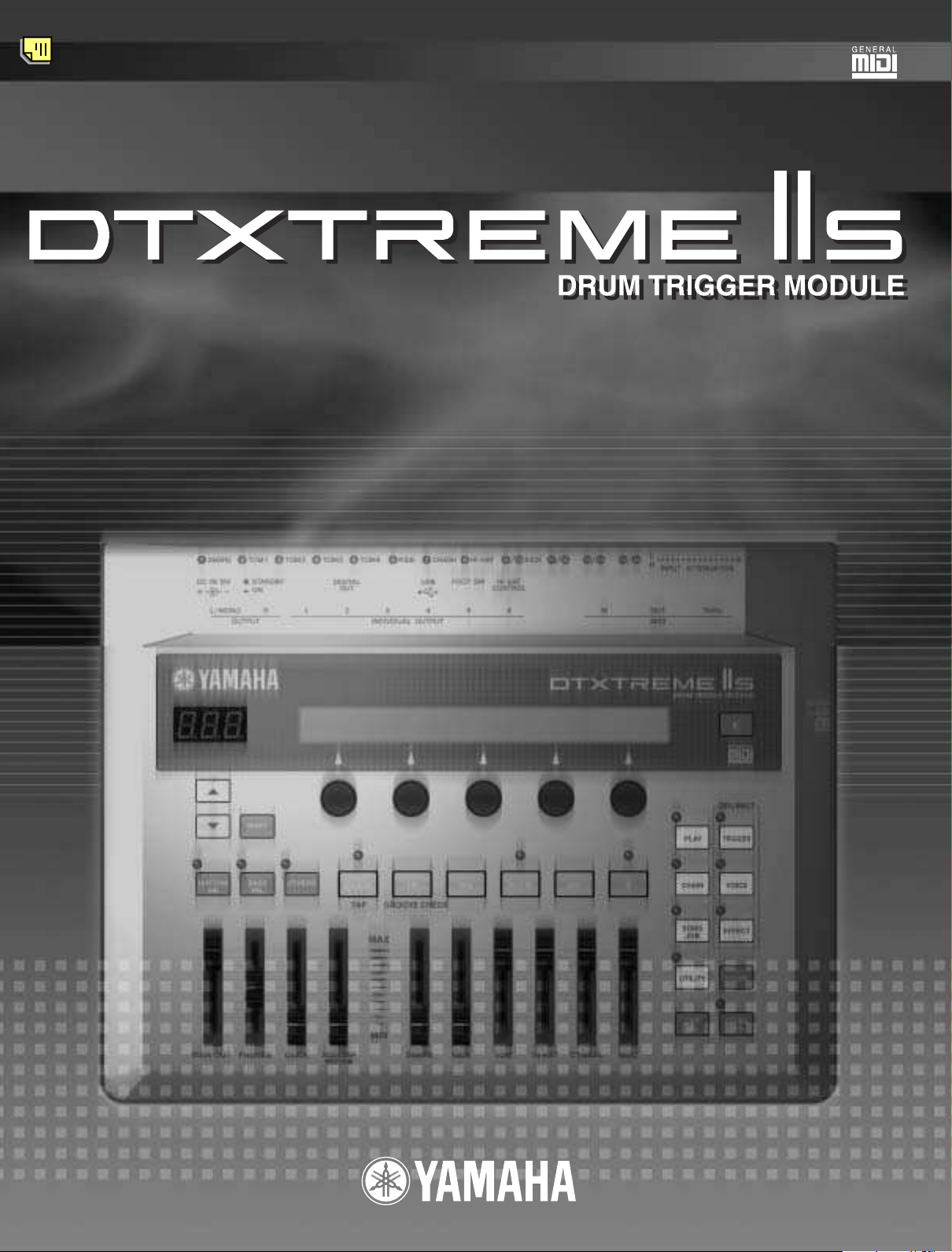
Thank you for purchasing the Yamaha DTXTREME IIs Drum Trigger Module.
The new DTXTREME IIs incorporates the highly acclaimed AWM2 tone generator and music
sequencer. In addition to the functions of its predecessor, DTXTREME IIs provides full support of the
current Yamaha trigger products and also sports a new USB port for MIDI connections (in addition to
traditional MIDI ports) — and has a built-in sampling feature that allows you to create your own drum
voices. With all these features, DTXTREME IIs makes an ideal trigger-based music system, offering the
drummer one of the best solutions for practicing at home, rehearsing in the studio, and performing on
stage. To fully enjoy your new instrument, please read this manual thoroughly. Also, keep this manual
in a convenient location for future reference.
How to Use This Manual
This manual describes all features and aspects of the DTXTREME IIs — for Playing (page 22), Editing
(page 33), and global, or Utility functions (page 73). To familiarize yourself with the Instrument, refer
to the following:
• Table of Contents (page 9) — for searching topics and features
• Panel Map (page 10) — for understanding each function on the panels at a glance
•
Index (page 97) — for looking up a specific feature using keywords and parameter names
• Cross-references throughout the text — for related information on specific topics
In addition, the following Icons are used to indicate specific types of Important information:
n Describes additional detailed information on a topic.
Indicates special cautions and Information to avoid loss of data, damage to the instrument, etc.
Contents of the Package
❏ DTXTREME IIs
❏ AC power adapter (PA-5C or PA-5D)
❏ Owner’s Manual
❏ Data List
❏ DTXTREME IIs Installation Guide
❏ USB-MIDI driver (CD-ROM)
Page 7

Features
The DTXTREME IIs is designed for professional drummers and has a comprehensive variety of flexible
drum-triggering features, a 64-note polyphonic tone generator compatible with the GM System Level 1
standard, as well as a built-in music sequencer that enables recording and playback of rhythm or
accompaniment patterns, and even lets you create an entire song. The instrument is ideal for virtually
any application — live performance, rhythm training, music creation and studio recording.
Drum Triggering
•Flexible external controls via 16 trigger inputs (total of 12 jacks), hi-hat controller jack, and footswitch
jack. These jacks can connect to any Yamaha triggering gear including traditional DTX/DTXPRESS
drum pads, DT-series trigger pickups, and the latest drum pads.
•Combined with the latest drum pads, DTXTREME IIs enables manual control of the drum voice tone
with a built-in knob.
•Freely adjustable trigger inputs. Each trigger input can be edited to suit the input device (type)
connected to the jack, letting you determine the sensitivity and other settings.
•Freely assignable voices. Using MIDI note numbers, each trigger input can be assigned a specific voice
from the internal tone generator. A set of trigger-to-voice configurations can be stored as a drum kit.
DTXTREME IIs stores up to 40 drum kits internally and up to 99 externally on convenient memory
cards. Also, DTXTREME IIs comes with 90 preset drum kits.
• Each trigger input can be set to play several MIDI note numbers simultaneously or sequentially,
enabling the playing of chords or melodic phrases, or even entire drum patterns with a single pad.
Tone Generator
•A variety of high-quality sounds (voices) in a 64-note polyphonic AWM2 (PCM) tone generator
compatible with the GM System Level 1 standard.
•Preset voices include 2,174 drum or percussion sounds and 128 keyboard sounds. DTXTREME IIs
offers dynamic drum voices, including high-quality Yamaha drum sounds, plus the latest samples and
looped sounds — guaranteed to inspire you as you play and create.
• An all-new sampling feature that lets you easily add your own samples to the drum kit. DTXTREME
IIs can also import samples (audio files) from the computer using memory cards.
• Each drum voice can be edited using various parameters for effects, volume, pan, pitch, and so on.
Effects
•High-quality digital reverb and chorus are provided as System effects. A versatile pair of separate
Insertion effects is also provided with 44 effect types.
• The Localizer provides a three-dimensional (3D) stereo effect that simulates natural sound when
monitored with stereo headphones.
7
Page 8

Music Sequencer
•A wide variety of Preset songs. Also, the DTXTREME IIs has internal memory space for up to
32 User songs.
•Song playback. In addition to a main song that is controlled by the panel transport buttons or external
MIDI events, DTXTREME IIs can play up to four pad-controlled songs assigned to a drum kit (pad
songs). These songs can be freely selected from the Preset and User songs.
•Groove check feature that measures timing accuracy when hitting the pads. This is especially useful for
practicing and learning purposes.
•Click feature for playing with the sequencer. You can choose a click sound separately from the drum
kit settings.
•Simple and easy two-track sequencer that can be used for real-time recording of your performances or
for recording external sequence data as User songs. Each track can contain several MIDI channels
(1 to 16). Since the DTXTREME IIs can sync with an external sequencer, you can start recording by
simply hitting a drum pad or Start button on the top panel or an external sequencer. The sequencer
also offers step recording so that you can manually create or edit a song step-by-step, using the
DTXTREME IIs LCD display.
•Selective playback feature. Since you can simply mute the drum or any other part in a song while
controlling the volume of each part, this is ideal for “minus-one” practice and so on.
Easy Operations and Useful Controls
•Backlit LCD display and LED display that provide clear visual information in any performing and
editing situation.
•Data entry knobs. These five knobs on the top panel provide easy accessibility to parameters shown in
the LCD display.
•Chain play feature that can play drum kits and songs in a specified order.
•Built-in mixing features. Top-panel volume slider controls let you easily adjust the volume balance
between instruments or parts (drum kit, accompaniment, and click). These slider controls can even
adjust the reverb return level for an entire drum kit, as well as the reverb send level for each instrument
in the kit. This simplifies the process of adjusting the reverb settings to suit the acoustics of your
surroundings. Two more dedicated slider controls are also provided for adjusting headphones and
click (metronome) volumes.
Interfaces and Expandability
•MIDI (IN, OUT, THRU) and USB ports offer connectivity between the DTXTREME IIs and
external MIDI devices — such as a computer or sequencer — for advanced recording and data storage
applications.
•Versatile sound outputs. In addition to the stereo outputs, there are six individual outputs for
separately sending specific sounds (snare drum, bass drum, tom, etc.) to an external mixer for further
processing. Also, the new digital output (S/PDIF) is useful to transfer the DTXTREME IIs stereo
sounds with digital quality.
•External sound input. Use the AUX IN stereo jack to connect an audio player (CD, MD, tape, etc.)
— and play the drum kit along with playback of your favorite songs. This jack can also be used for
sampling from the connected audio source.
•External storage using the memory card (SmartMedia). You can use the memory card to store and read
data including drum kits, songs, and chains. The memory card can also be used to supply a waveform
sample (audio file) for sound expansion.
8
Page 9
Table of Contents
Introduction . . . . . . . . . . . . . . . . . . . . . . . 6
How to Use This Manual . . . . . . . . . . . . . 6
Contents of the Package . . . . . . . . . . . . . 6
Features . . . . . . . . . . . . . . . . . . . . . . . . . . 7
Panel Map . . . . . . . . . . . . . . . . . 10
Top Panel . . . . . . . . . . . . . . . . . . . . . . . . 10
Rear Panel . . . . . . . . . . . . . . . . . . . . . . . 12
Setup . . . . . . . . . . . . . . . . . . . . 14
Pads and Triggers . . . . . . . . . . . . . . . . . 14
Compatible Products . . . . . . . . . . . . . . . 14
Peripherals . . . . . . . . . . . . . . . . . . . . . . . 17
MIDI Connections . . . . . . . . . . . . . . . . . 18
Power . . . . . . . . . . . . . . . . . . . . . . . . . . . 19
Connecting to a Power Source . . . . . . . 19
Power-On Sequence . . . . . . . . . . . . . . . 19
Basic Operations . . . . . . . . . . . . 20
Matching Trigger Inputs
with Connected Pads . . . . . . . . . . . . . . 21
Edit Section . . . . . . . . . . . . . . . . 33
DTXTREME IIs as Drum System . . . . . . 33
From Trigger Input to Sound Output . . . 33
Memory, Buffer, and Store Operation . 35
Trigger Settings . . . . . . . . . . . . . . . . . . . 36
Edit Pages and Basic Operations . . . . . 36
Voice Settings . . . . . . . . . . . . . . . . . . . . . 48
Edit Pages and Basic Operations . . . . . 48
Effect Settings . . . . . . . . . . . . . . . . . . . . 55
Reverb . . . . . . . . . . . . . . . . . . . . . . . . . . 55
Chorus . . . . . . . . . . . . . . . . . . . . . . . . . . 55
Insertion Effects 1 and 2 . . . . . . . . . . . . 55
Localizer . . . . . . . . . . . . . . . . . . . . . . . . . 55
Song Recording and Editing . . . . . 60
Features of the Two-track Sequencer . 60
Preparation for Recording . . . . . . . . . . . 60
Recording Operations . . . . . . . . . . . . . . 62
Song Job Features . . . . . . . . . . . . . . . . . 65
Edit Pages and Basic Operations . . . . . 65
Panel Map
Setup
Basic
Operations
Play Section
Edit Section
Song Recording
and Editing
Utility Features
Appendix
Play Section . . . . . . . . . . . . . . . 22
Basic Items . . . . . . . . . . . . . . . . . . . . . . . 23
Playback Controls . . . . . . . . . . . . . . . . . 24
Click Playback . . . . . . . . . . . . . . . . . . . . 24
Song Playback . . . . . . . . . . . . . . . . . . . . 24
Slider Controls . . . . . . . . . . . . . . . . . . . . 26
Tap Tempo Feature . . . . . . . . . . . . . . . . 28
Groove Check Feature . . . . . . . . . . . . . . 29
Chain Feature . . . . . . . . . . . . . . . . . . . . . 30
Switching the Chain Display . . . . . . . . . 30
Creating or Editing a Chain . . . . . . . . . . 30
Playing a Chain . . . . . . . . . . . . . . . . . . . 32
Utility Features . . . . . . . . . . . . . . 73
Edit Pages and Basic Operations . . . . . 73
Sampling Feature . . . . . . . . . . . . . . . . . . 82
Memory Card Feature . . . . . . . . . . . . . . 85
Appendix . . . . . . . . . . . . . . . . . . 90
Handling the Memory Card
(SmartMedia™*) . . . . . . . . . . . . . . . . . . . 90
Troubleshooting . . . . . . . . . . . . . . . . . . . 91
Error Messages . . . . . . . . . . . . . . . . . . . 94
Specifications . . . . . . . . . . . . . . . . . . . . . 96
Index . . . . . . . . . . . . . . . . . . . . . 97
The illustrations and LCD screens as shown in this Owner’s Manual are for instructional purposes only, and may appear
somewhat different from those on your instrument.
9
Page 10
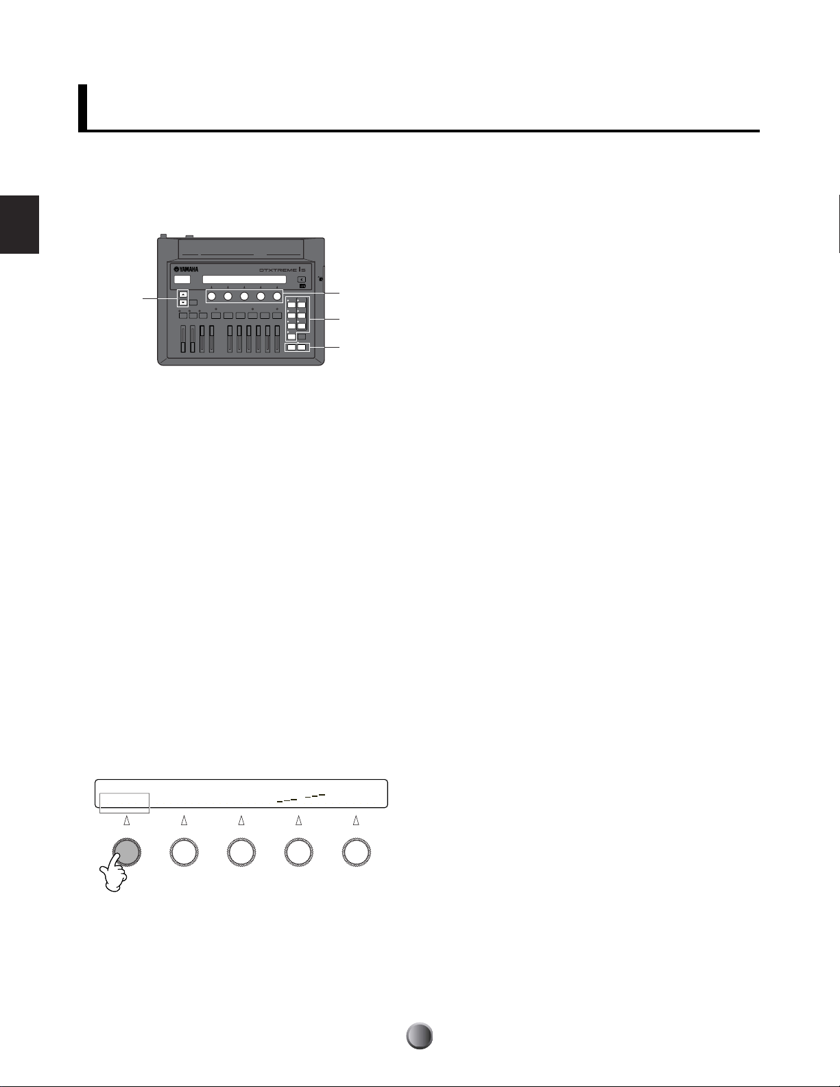
PANEL MAP
PHONES AUX IN AUX IN VOL
Panel Map
Panel Map
Top Panel
Selecting Playback Parts
6
RHYTHM/INS button
During song playback, pressing this
button activates or cancels playback of
the rhythm part. During step recording,
it is used to insert data at the cursor
point.
7
BASS/DEL button
During song playback, pressing this
button activates or cancels playback of
the bass part. During step recording, it
is used to delete data at the cursor
point.
Transport Controls
)
Reset button ( )
Pressing this button while the song is
stopped moves the playback point to
the beginning of a song (unavailable
during song playback).
By simultaneously holding down the
SHIFT button and pressing this button,
you can use the Groove Check feature
(page 29).
!
Rewind button (
Pressing this button moves the
playback point to the previous measure
(unavailable during song playback).
G
▼
▲
Basic Operations
3
2
1
SHIFT button
Use this button to modify the
original function of specific panel
controls (button, knob, and slider).
8
OTHERS button
During song playback, pressing this
button activates or cancels playback of
parts other than the rhythm and bass
parts.
9
CLICK button
Pressing this button activates or
cancels playback of the click
(metronome) sound. By simultaneously
holding down the SHIFT button and
pressing this button, you can use the
Tap Tempo feature (page 28).
@
Start/Stop button ( )
Pressing this button starts or stops
playback or recording of a song.
Pressing this button during song
playback pauses playback. Pressing
the button a second time resumes song
playback from the stopped point.
#
Forward button (H)
)
Pressing this button moves the
playback point to the next measure
(unavailable during song playback).
$
Record button (●)
Pressing this button enables recording
standby.
Page buttons ( ▲ / ▼ )
While editing each function, use
these buttons to go to the next
page (
) or the previous page ( ▲ ).
Hold down either button to scroll
forward or backward between
pages. By simultaneously holding
down the SHIFT button and
pressing each button, you can
move to the first (
page very quickly.
) or last ( ▼ )
+
MAIN OUT PHONES CLICK ACCOMP
Displays
The LCD shows information and
data for various DTXTREME IIs
operations, and the LED display
indicates the current drum kit or
tempo value.
FOOT SWDC IN 12V
USB
564
L MONO
OUTPUT
STANDBY
ON
R
DIGITAL
OUT
12
3
INDIVIDUAL OUTPUT
3
2
1
SHIFT
6
78 ) !
RHYTHM
BASS
INS
DEL
OTHERS
9
CLICK
TAP
%^&* (º
REVERB
5
GROOVE CHECK
MAX
MIN
SNARE KICK
fi fl ‡
Front Panel
CCCC PHONES jack
Connect headphones here to monitor the
stereo mix of the DTXTREME IIs sounds.
DDDD AUX IN jack
Connect the line output from an external
audio device here. You can play along with
an external audio source (page 17), as well
as record external audio as a waveform sample (page 83).
EEEE AUX IN VOL control
Adjusts the input level of an audio source connected to the AUX IN jack.
fi fl ‡
Master Volume Controls
% MAIN OUT slider
Adjusts the output volume of the stereo
mix from the OUTPUT L/MONO and R
jacks.
^ PHONES slider
Adjusts the output volume of the stereo
mix from the PHONES jack. This is
independent from the MAIN OUT slider
setting.
10
& CLICK slider
Adjusts the output volume of the click
sound from the specified output jack
(page 81).
* ACCOMP/REVERB slider
Adjusts the output volume except for
rhythm sounds (MIDI channel 10).
Moving this slider while holding down
the SHIFT button lets you control the
entire return level of the reverb effect.
Page 11
Side Panel
4 Audition button
Press this button to audition a
target voice while editing a drum
kit, just like hitting a pad for that
voice. Pressing this button while
holding down the SHIFT button
can stop playback of a looped
voice or a pad song.
L
116
H
IN OUT
$
INPUT ATTENUATION
MIDI
DRUM TRIGGER MODULE
∞
PLAY
§
CHAIN
¶
SONG
JOB
•
UTILITY
‹
EXITNOEXIT
NO
HI-HAT
CONTROL
@
#
¡™£¢
TOM HI-HAT CYMBAL MISC
5 Data entry knob
Use each knob to set the
corresponding parameter value
shown above it in the LCD. By
simultaneously holding down the
SHIFT button and turning the knob,
you can increase or decrease the
value in large jumps.
THRU
°
4
DRUMKIT
ª
TRIGGER
‚
VOICE
⁄
EFFECT
¤
STORE
›
ENTER
YES
CARD
3.3V
°
CARD slot
Insert an optional SmartMedia (3.3V) here for use as a memory card (page 90).
Function Modes
∞ PLAY button
Press this button to select and play a
drum kit or song (basic operation
mode).
§ CHAIN button
Press this button to play different drum
kits and songs sequentially in a chain.
¶ UTILITY button
Press this button for system settings,
sampling feature, and memory card
functions.
• SONG JOB button
Press this button to edit a User song.
ª TRIGGER button
Press this button to edit trigger
parameters for a drum kit.
‚ VOICE button
Press this button to edit voice
parameters for a drum kit.
⁄ EFFECT button
Press this button to edit effect
parameters for a drum kit.
Other Operations
¤ STORE button
Press this button to store a drum kit or
a chain.
‹ EXIT/NO button
Press this button to exit from each
function mode, or to cancel an
operation when a confirmation
message is shown in the LCD.
› ENTER/YES button
Press this button to determine a
parameter value, or execute an
operation when a confirmation
message is shown in the LCD.
Panel Map
Volume Controls of Rhythm & Drum Instruments
( SNARE slider
Adjusts the snare drum volume.
º KICK slider
Adjusts the bass drum volume.
¡ TOM slider
Adjusts the volume of the toms.
™ HI-HAT slider
Adjusts the hi-hat volume.
£ CYMBAL slider
Adjusts the cymbal volume.
¢ MISC slider
Adjusts the volume of miscellaneous
rhythm or percussion sounds —
other than snare and bass drums,
toms, hi-hats, and ride and crash
cymbals.
n By simultaneously holding down
the SHIFT button and moving
the slider controls ( to ¢, you
can adjust the reverb send level
or the output level from the
INDIVIDUAL OUTPUT jack for
the corresponding instrument
(page 27).
11
Page 12
PANEL MAP
Panel Map
Panel Map
Rear Panel
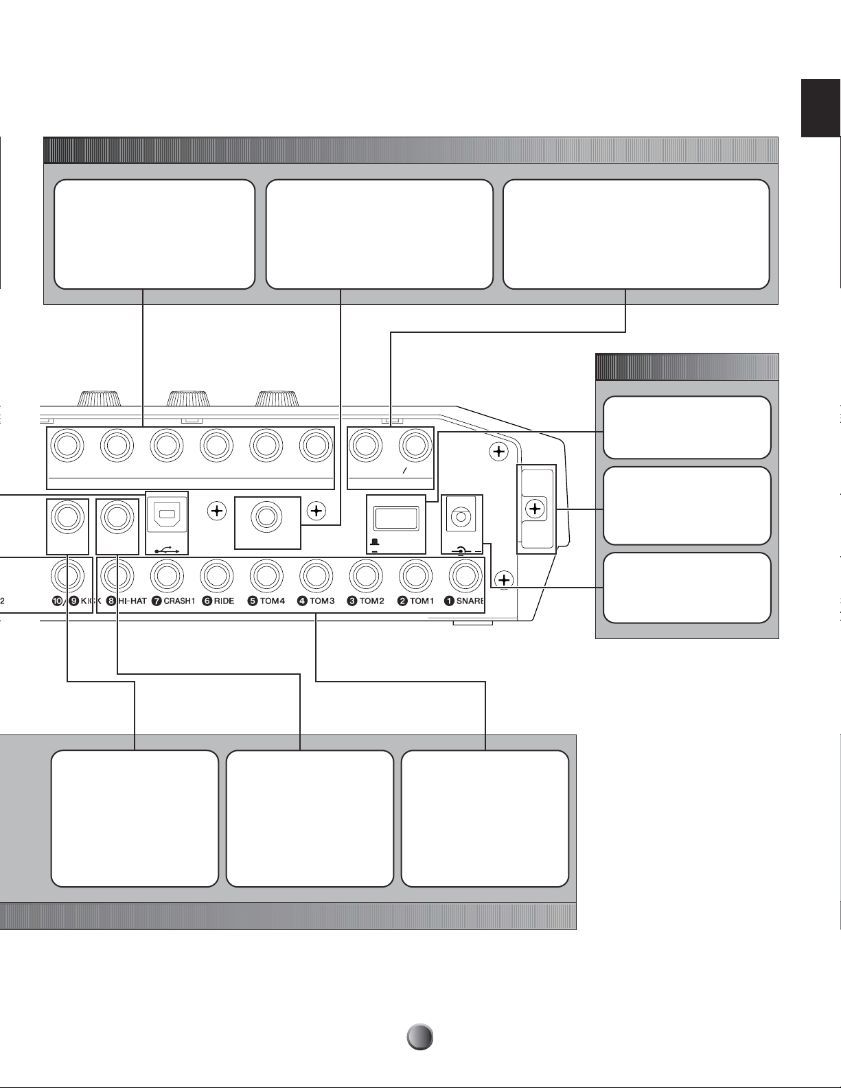
MIDI I/O
MIDI IN, OUT, and THRU terminals
Use the MIDI terminals to transfer MIDI events between
the DTXTREME IIs and an external device such as
sequencer or tone generator, for an extended MIDI
system (page 18).
USB port
By simply connecting the DTXTREME IIs to a
computer with a single USB cable, you can transfer
MIDI events between these two devices. You do not
need additional MIDI cables, MIDI interface, or a
serial port on the computer (page 18).
THRU
MIDI
INOUT
INPUT ATTENUATION
switches
Each DIP switch corresponds to a
trigger input jack and adjusts its
sensitivity. This is useful when
connecting pads and trigger
sensors with a lower trigger signal.
Set the DIP switch to the H position
to boost (increase) the trigger
signal level.
Trigger Inputs
H
L
16
9
INPUT ATTENUATION
18
9/) KICK to %/^
Each of these trigger input jacks is designed to accept two separate
trigger signals from two mono (single) pad connected using a Y-shaped
cable with a stereo phone plug at the trigger input end and two mono
plugs at the pads’ ends. If connected using a mono cable (a shielded
cable with a mono phone plug at each end), the trigger signal will be
routed only to odd-numbered trigger inputs (9, !, #, or %).
See “Compatible Products” (page 14) for a recommended pad product
for each trigger input.
12
Page 13
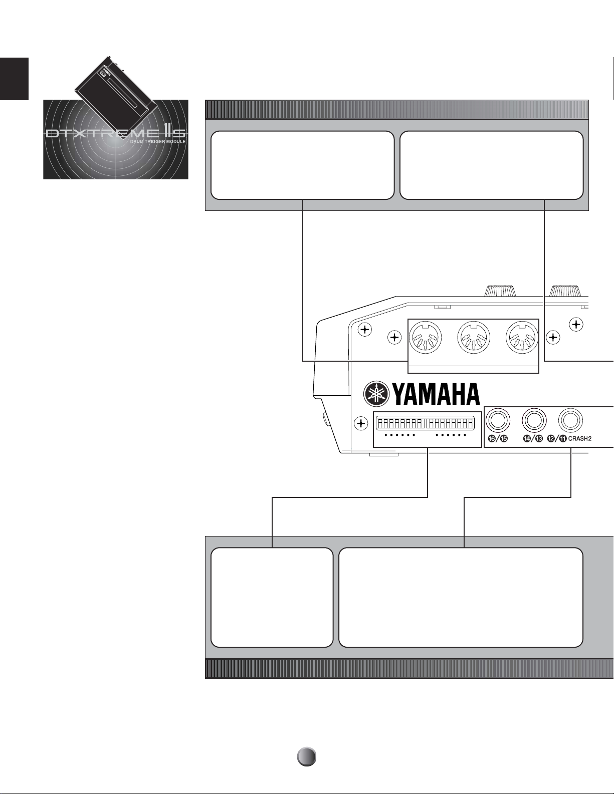
Audio Outputs
Panel Map
INDIVIDUAL OUTPUT 1 to 6 jacks
Each of these jacks can separately output
any specified drum voice (page 53) or click
sound (page 81) —useful for sending each
instrument signal to an external mixer for live
performance or recording session.
6
HI-HAT
CONTROL
54
INDIVIDUAL OUTPUT
FOOT SW
USB
3
DIGITAL OUTPUT jack
Connect to a coaxial digital input (S/P DIF) on
an external audio device. This jack digitally
outputs stereo audio signals identical to those
from the OUTPUT L/MONO and R jacks, but not
affected with the MAIN OUT
setting (the digital jack always outputs audio
signals at a maximum volume level).
12
DIGITAL OUT
R
OUTPUT
STANDBY
ON
% volume slider
L MONO
DC IN 12V
+
OUTPUT L/MONO and R jacks
Outputs line level stereo-mixed audio signals from the
DTXTREME IIs to other audio equipment (amp, mixer, etc.).
Use a pair of shielded cables with a 1/4-inch phone plug
on one or both ends. Connect those cables to both
L/MONO and R jacks if you want to output in stereo.
Connect only to the L/MONO jack if you want to output
in mono.
Power
STANDBY/ON switch
Tur ns the DTXTREME IIs on or off.
Cable hook
Fix the DC power cord of the
supplied AC power adapter here to
ensure the plug will not come
loose.
DC IN jack
Connect the supplied AC power
adapter (PA-5C or PA-5D) here.
HI-HAT CONTROL jack
Connect a foot controller for
hi-hats (Yamaha HH series) here.
You can also use this controller as
a MIDI controller (page 45).
FOOT SW jack
Connect a foot switch (Yamaha
FC4 or FC5) here. You can assign
various functions to the foot switch
(page 46).
1 SNARE to 8 HI-HAT
Each of these trigger input jacks
is designed to accept two
separate trigger signals from a
stereo (dual) pad connected
using a stereo cable (a shielded
cable with a stereo phone plug at
each end). If you connect a mono
pad, only the head-generated
trigger signal can be used.
13
Page 14
Setup
Setup
Pads and Triggers
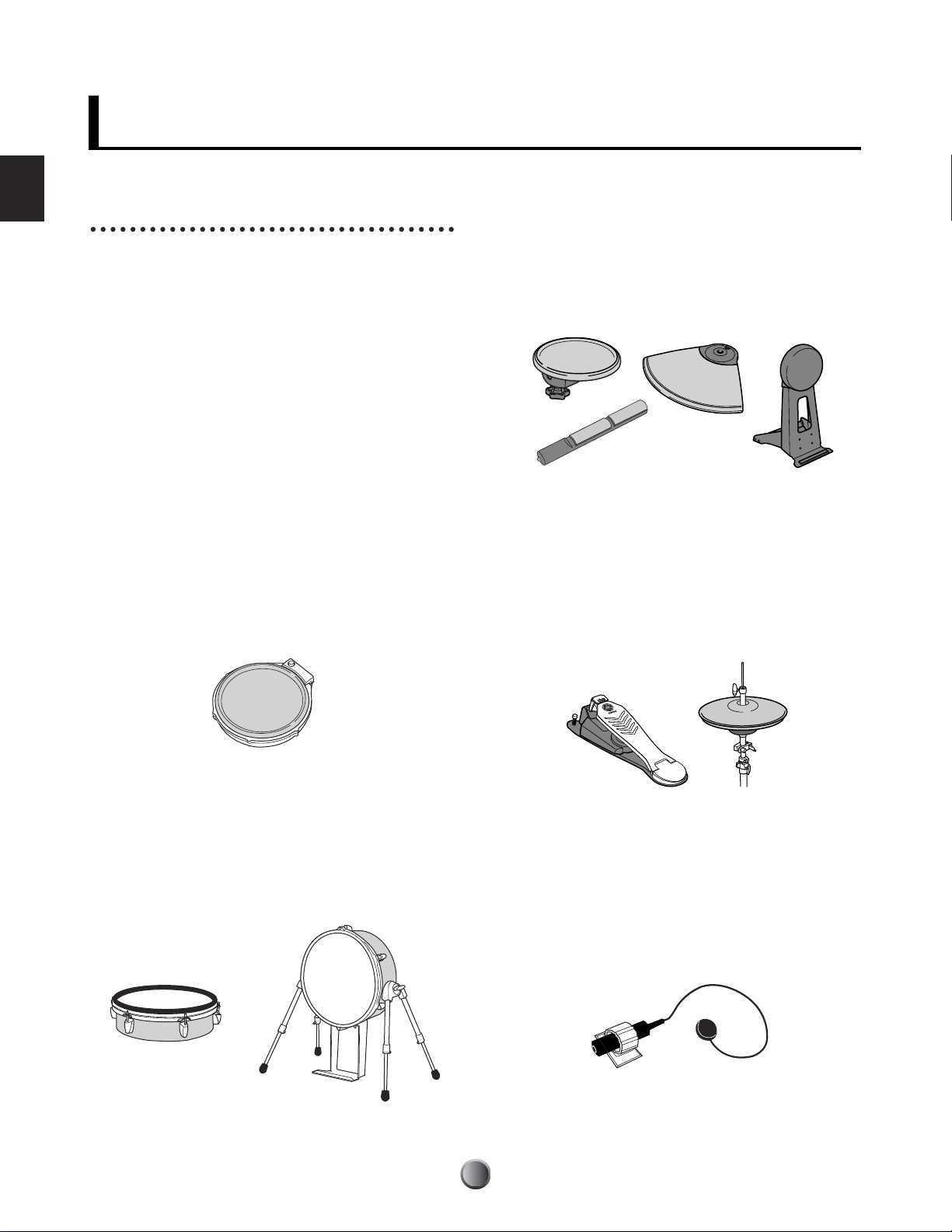
Compatible Products
You can use the DTXTREME IIs with any currently available
Yamaha pad products. Since each pad is designed for a
specific purpose and has its own specifications, you’ll need to
check which product is most suitable for connecting to a
specific DTXTREME IIs trigger input. When you purchase
additional pads for your kit, refer to the following table for
optimum compatibility.
n For detailed information on Yamaha pad products, refer to the
DTXTREME IIs product brochure or your local Yamaha website.
Drum Pad (TP100/TP120SD)
A new series of drum pads that adopt a newly developed
rubber head. When used for the snare drum and toms, these
pads can produce real continuous tone change by three-zone
position sensing. These pads also employ a new pad controller
for adjusting the snare or tom tone (such as tuning) while
playing the kit.
Rubber Pad (TP/PCY/KP/BP series)
Standard lineup of drum and trigger pads made of rubber
material. In addition to traditional dual and single trigger
pads (dual pads have a rim switch), several new pads with
three-zone position sensing feature are also available. These
pads are convenient for triggering pad songs or switching a
drum kit or song in chain play.
Hi-hat Controller (HH/RHH series)
Indispensable for subtle hi-hat work with a DTXTREME IIs
drum kit. Choose your favorite combination of the hi-hat
"pedal and cymbals," such as HH-series controller and TPseries pad. You can even choose a real hi-hat stand (such as
Yamaha HS series) and an RHH130 pad with two zone
position sensing.
Real Head Pad (RHP/KP series)
These pads feature a wooden drum shell made of plied birch
and mahogany, and a real drum head — just as on acoustic
drums. This series include three different pads for bass drum,
snare drum, and toms and designed especially for use with
Yamaha System Drums.
Drum Trigger (DT series)
These trigger pickups are designed for attaching to acoustic
drums, making them ideal for expanding the capabilities of
your acoustic drum kit with the DTXTREME IIs electronic
sounds. Each pickup can produce a single trigger. Keep in
mind that attaching two drum triggers to a single snare drum
will not produce the same effect as using a dual trigger pad.
14
Page 15
Attaching a Drum Trigger
To use an acoustic drum as a triggering device, you
will need to attach a Yamaha DT-series drum trigger.
Observe the following precautions and attach the
trigger properly as described in the diagrams below.
Attaching to a Tom
Attach the sensor portion of the trigger near the rim
on the shell. Ensure that the sensor does not touch the
rim or other parts in the drum kit (snare drum, other
toms, percussion instruments, etc.).
• First remove dust or oily dirt from the batter head or
drum shell to which you will apply the sensor using a
cloth dampened with water or a alcohol (use no
chemical solvents), then apply the sensor.
• Cover the sensor and cord with tape to avoid
accidental disconnection that may be caused by
drum vibrations.
• Double triggering may occur if the drum head
produces a sustained sound or irregular vibrations.
If this is the case, change the tuning or mute the
head to avoid unnecessary vibrations. It is
recommended to use the ring mute.
Attaching to a Bass Drum
Attach the sensor portion of the trigger near the rim
on the batter head. Ensure that the sensor does not
touch the rim.
Sticky tape
Setup
Detaching a Drum Trigger
Yo u’ll need to detach the trigger when replacing the
drum head. Before removing the head, remove the
sensor portion of the trigger carefully using a knife or
similar object. Be careful not to pull the cord.
n When replacing the sensor, remove any remnants of the
old tape completely and then re-attach it using new tape.
Such remnants may cause problems regarding trigger
sensitivity (poor or no triggering, double triggering, etc.).
Attaching to a Snare Drum
Attach the sensor portion of the trigger near the rim at
the opposite end to the player, on the batter head.
Ensure that the sensor does not touch the rim.
Sticky tape
15
Page 16
Setup
Trigger Connections
Referring to the following table, connect each pad to the appropriate trigger input jack on the DTXTREME IIs
rear panel. Appropriate names are printed beside each jack, making it easy to make the relevant pad connections.
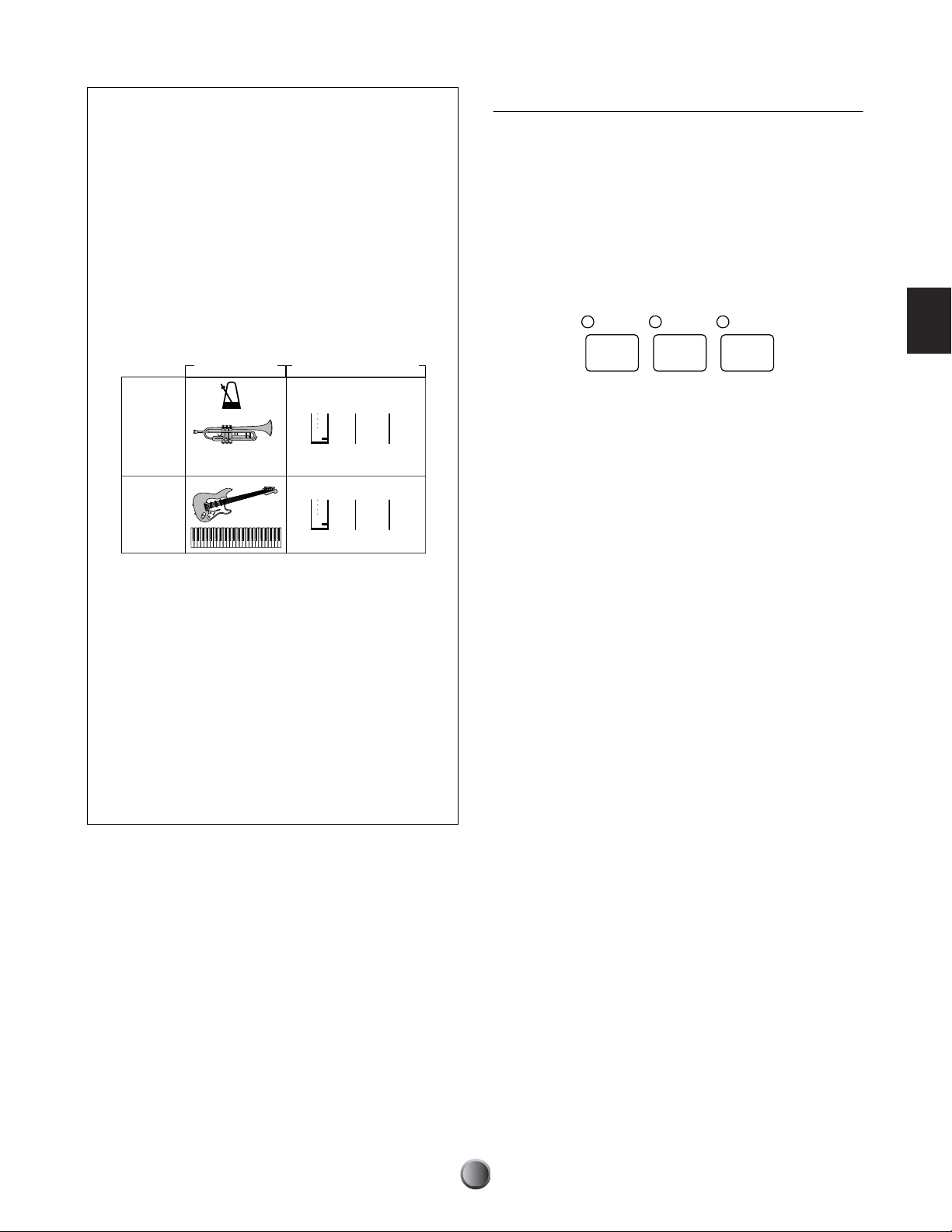
Pad-to-Input Matching Chart
Y=Yes, N=No
Trigger input
Rim configurations
3-zone detection YYYYNN
Pad controller compatibility
New Model No. Model Name 1 2, 3, 4, 5 6, 7 8 9/10
TP60 Tom Pad ▲▲(▲) ▲ (▲) ▲
TP65 Tom Pad ●●(●) ● (▲) ▲
TP65S Tom Pad ●●(●) ● (▲) ▲
TP80 Tom Pad ▲▲(▲) ▲ (▲) ▲
TP80S Tom Pad ■■(■) ■ (▲) ▲
✓ TP100 Tom Pad ●●(●)(●)(▲) ▲
✓ TP120SD Snare Pad ●●(●)(●)(▲) ▲
RHP80 Real Head Pad ■■(▲) ▲ (■) ■
RHP100 Real Head Pad ■■(▲) ▲ (■) ■
RHP120 Real Head Pad ■■(▲) ▲ (■) ■
RHP120SD Real Head Pad ■■(▲) ▲ (■) ■
✓ RHH130 Hi-hat Pad (■)(■)(■) ● (▲)(▲)
PCY10 Cymbal Cap Pad (▲)(▲) ▲ (▲)(▲) ▲
PCY60 Cymbal Pad (▲)(▲) ▲ (▲)(▲) ▲
PCY65 Cymbal Pad (▲)(▲) ▲ (▲)(▲) ▲
PCY65S Cymbal Pad (■)(■) ■ (■)(▲) ▲
PCY80 Cymbal Pad (▲)(▲) ▲ (▲)(▲) ▲
PCY80S Cymbal Pad (■)(■) ■ (■)(▲) ▲
✓ PCY130 Cymbal Pad (▲)(▲) ▲ (▲)(▲) ▲
✓ PCY130S Cymbal Pad (■)(■) ■ (■)(▲) ▲
✓ PCY150S Cymbal Pad (●)(●) ● (●)(▲) ▲
KP60 Kick Pad (▲)(▲)(▲)(▲)(▲) ▲
KP65 Kick Pad (▲)(▲)(▲)(▲) ▲▲
KP80 Kick Pad (▲)(▲)(▲)(▲) ▲▲
KP80S Kick Pad (▲)(▲)(▲)(▲) ▲▲
KP120 Real Kick Head Pad (▲)(▲)(▲)(▲) ▲▲
BP80 Bar Pad (▲)(▲)(▲)(▲)(■) ■
DT10 Drum Trigger ▲▲▲▲▲ ▲
DT20 Drum Trigger ▲▲▲▲▲ ▲
DT30 Drum Trigger ▲▲▲▲▲ ▲
HH80A Hi-hat Controller
HH60 Hi-hat Controller
HH65 Hi-hat Controller
● .......... Three voices available from pad, rim 1 and rim 2.
■ .......... Two voices available from pad and rim.
▲.......... One voice available from pad.
* Bracketed combinations indicate that they do not match the preset voice.
n An HH-series hi-hat controller connected to the FOOT SW jack can be used as a second kick pedal (page 46).
n For trigger input jacks connected with drum triggers, set their INPUT ATTENUATION switches to the H position (otherwise, set to
the L position) and set their trigger sensitivity for the drum trigger (page 36).
1
Snare
switch &
piezo
YYNNNN
2, 3, 4, 5
Tom
switch &
simple piezo
6, 7
Cymbal
switch only switch only piezo only piezo only
8
Hi-Hat
9/10
Kick
11/12 to 15/16
Cymbal &
11/12 to 15/16
others
16
Page 17
Peripherals
In addition to the built-in triggering system, DTXTREME IIs also features a built-in MIDI tone generator, builtin music sequencer, and mixing functions with various effects. This all-in-one self-contained system makes it
possible to play the DTXTREME IIs system right out of the box — once you finish pad connections and turn the
system on. What’s more, the system can easily be expanded with other peripheral devices since the instrument
supports various types of connections. Here we’ll show you some typical audio and MIDI connections so that you
can learn how to fit the DTXTREME IIs system into your own working environment.
Audio Connections
When recording your performance on a DTXTREME IIs drum kit or sending its sounds to a mixer, connect your
equipment as follows (Yamaha AW4416 works in both situations as mixer and recorder):
Setup
AW4416
LINE IN
INDIVIDUAL
OUTPUT
CD player MD recorder
AUX OUT
LINEOUT
AUX IN
DTXTREME IIs
DRUMTRIGGERMODULE
DIGITAL
OUT
DIGITAL
IN
The OUTPUT (L/MONO and R) and INDIVIDUAL OUTPUT (1 to 6) jacks produce line level audio signals
regardless of whether headphones are connected or not. These jacks are mono phone type. To make audio
connections via these jacks, use cables with a mono phone plug for the DTXTREME IIs and an appropriate plug
for the other device.
Use both of OUTPUT jacks (L/MONO and R) for stereo output. If the other device has a mono input,
use the L/MONO jack only.
Connect a set of headphones to the PHONES jack for monitoring the stereo output (identical to that of the
OUTPUT jacks). The sounds output from the INDIVIDUAL OUTPUT jacks cannot be heard from the
headphones connected to the PHONES jack.
The DIGITAL OUTPUT terminal allows you to output the stereo signal as digital audio to an audio device that
has a coaxial-type digital input (S/PDIF). The stereo output from the DIGITAL OUTPUT jack is identical to that
output from the OUTPUT jacks.
External audio signals input to AUX IN can be monitored together with the DTXTREME IIs sounds via
headphones connected to the PHONES jack (page 75), and can be recorded as a waveform sample for an
additional drum voice (page 83). In either case, you can adjust the AUX IN input level using the AUX IN VOL
control.
17
Page 18
MIDI Connections
DTXTREME IIs has USB and MIDI (IN/OUT/THRU) ports, and you can use these to transfer MIDI events to/
from external MIDI-equipped devices.
USB
Setup
DRUMTRIGGERMODULE
Computer
DTXTREME IIs
The USB port allows bi-directional transfer of MIDI events between the DTXTREME IIs and a personal
computer with a single USB cable. With a USB connection, you can record your performance on the drum kit —
and even the song playback of the Instrument — with MIDI sequencer software on your computer. You can also
play the internal tone generator of the DTXTREME IIs with a MIDI sequence from the computer or capture it to
the Instrument as a DTXTREME IIs song.
MIDI
MIDI
OUT
IN
SU200 AN200
MIDI
OUT
DTXTREME IIs
MIDI
IN
MIDI THRU
DRUMTRIGGERMODULE
The MIDI ports offer one-way transfer of MIDI events. Use MIDI OUT to play an external sound module with a
DTXTREME IIs drum kit or song. Use MIDI IN to control the internal tone generator from an external device.
You can use MIDI THRU to connect an additional external sound module, controlling it from a MIDI controller
connected to MIDI IN. If you want to share an external sound module with DTXTREME IIs and an external
controller, connect the controller to MIDI IN, connect the module to MIDI OUT, and use the MIDI merge
function (page 79).
n You cannot use USB and MIDI ports simultaneously. When you connect a USB cable to the DTXTREME IIs, the MIDI ports are
automatically disabled. If you make MIDI and USB connections at the same time, external devices connected to any MIDI port will
not function. However, if you want to make a temporary USB connection to a computer for some reason, you can keep the MIDI
devices connected to the DTXTREME IIs, since the USB connection does not affect or harm the MIDI devices at all.
18
Page 19
Power
Connecting to a Power Source
Make sure that the STANDBY/ON switch is in the STANDBY position. Plug the supplied AC power adapter to
the DC IN jack on the DTXTREME IIs rear panel. Fix the power cord to the cable hook, ensuring that the
adapter plug does not come loose. Connect the adapter to an AC outlet.
L MONO
R
OUTPUT
DC IN 12V
STANDBY
ON
+
SNARETOM1TOM2
123
Always use the supplied AC power adapter (PA-5C or PA-5D). Use of a power adapter other than the type specified may cause a
malfunction or result in damage to the DTXTREME IIs. Also, unplug the power adapter from the AC outlet if the DTXTREME IIs
is not used for an extended period of time.
Setup
Cable fook
To AC outlet
AC power adapter
Power-On Sequence
After you’ve made all necessary connections (trigger, audio, MIDI), turn down all volume controls of the
DTXTREME IIs and other audio equipment. Turn on your system in the order of the audio signal flow (first the
mixer, then the amplifier or powered speakers).
MIDI master devices
The DTXTREME IIs displays a splash screen, and then shows PLAY mode screen. Now you can start playing.
If you are ready, see the next page for detailed explanations on how to use the DTXTREME IIs system.
n When turning off your system, first turn down all volume controls for the audio equipment, then turn off devices in the reverse order
of the audio signal flow.
DRUMTRIGGERMODULE
DTXTREME IIs
KIT=P1 SONG=P1 TEMPO BEAT CLICK
Kit name Songname =107 4/4
Audio equipment (first mixer, then amplifier)
19
Page 20
Basic Operations
All of the DTXTREME IIs operations are done using the
various panel controls and the two displays. In this section,
we’ll explain how to use these controls.
Basic Operations
1 The DTXTREME IIs has seven function modes. You can
2 Use the Page buttons (▲/▼) to switch among the
DRUMTRIGGERMODULE
2
3
1
4
select each mode by simply pressing the corresponding
mode button. An indicator light shows which mode you
are currently working in. When you turn the unit on or
exit from the other six modes, the DTXTREME IIs will
go into PLAY mode and the PLAY indicator will light
(you cannot exit from this basic mode).
available setting pages (LCD screens).
4 If you are working in a specific page or performing a
specific operation, and the ENTER/YES indicator flashes,
this is a prompt indicating you should answer YES or NO.
Simply press the ENTER/YES button to execute the
operation, or press the EXIT/NO button to cancel it.
Pressing the STORE button to save edited data also causes
the ENTER/YES indicator to flash. In this case, press the
ENTER/YES button to save the data, or press the EXIT/
NO button to cancel the store operation.
n Since most settings are automatically stored into the memory of
the DTXTREME IIs, you do not need to execute the store
operation unless prompted.
Basically, this is all you need to know to start working with
and playing your DTXTREME IIs. Any crucial operations
are preceded by a confirmation display that allows you to
cancel the operation as needed. However, you must first
complete one very important setting before actually playing
with the DTXTREME IIs. Here is a chance to put into
practice some of the things you’ve just learned...
3 There are five knobs beneath the LCD display. Each knob
corresponds to a parameter shown above in the LCD
screen and can be used to set the value. To advance
rapidly or jump through the available values,
simultaneously hold down the SHIFT button and turn
the appropriate knob.
When you are editing a drum kit and want to set the same
parameters for different targets (trigger inputs 1 to 16,
etc.), you can use the leftmost knob to conveniently
switch the target without changing the screen you are
working in.
[TrgSens1] Type Gain Curve PadCtrl
Input=1 RHP 32 3 - pitch
20
Page 21
Matching Trigger Inputs with
Trigger Set
Connected Pads
Since each drum pad has its own characteristics, you need to
appropriately set the trigger inputs to make most of the
connected pads. The DTXTREME IIs features six different
trigger sets for typical combinations of pads. Select the set
that best matches your drum kit.
1. Press the UTILITY button. Then press the Page button
(▼) several times until the [UT 6] SYSTEM TRIGGER
page appears.
2. Select a trigger set (TrgSet) from the six presets. If you
purchased DTXTREME IIs with a recommended pad set,
one of the six presets (type1 to type6) will perfectly match
your setup.
Tr igger Set
[UT 6] TrgLink TrgByps TrgSet EdgeAdj
SYSTEM indiv off type1 +20
Trigger
Input Jack
SNARE 1
TOM1 2
TOM2 3
TOM3 4
TOM4 5
RIDE 6
CRASH1 7
HI-HAT 8
KICK 9
(reserved)
CRASH2 11
(reserved) 12 any TP
Type1 Type2 Type3 Type4 Type5 Type6
TP
120SDTP120SD
TP
100TP65S
TP
100TP65S
TP
100TP65S
TP
100TP65S
PCY
150S
any
PCY
RHH
130
anyKPanyKPKP
anyKPanyKPKP
10
any
PCY
150S
RHH
PCY
any
PCY
130
any
PCY
any
RHP
any
RHP
any
RHP
any
RHP
any
RHP
PCY
150S
any
PCY
RHH
130
120KP120
120KP120
any
PCY
any
RHPTP65S
anyTPanyTPany
anyTPanyTPany
anyTPanyTPany
anyTPanyTPany
any
PCY
PCY
any
PCY
PCY
anyTPanyTPany
any
PCY
PCY
any
any
any
PCY
any
any
PCY
anyKPany
anyKPany
any
any
PCY
TP
TP
TP
TP
TP
TP
KP
KP
Basic Operations
(reserved) 13 any PCY
(reserved) 14 any TP
(reserved) 15 any TP
(reserved) 16 any TP
n “Any” specified pad will not always produce all sounds available.
For more information, refer to “Trigger Connections” (page 16).
3. When you complete the setting, press the EXIT/NO
button and return to PLAY mode.
Now you are ready to start playing with the DTXTREME IIs
drum kit. Go to the Play Section to learn some of the
performance functions of the DTXTREME IIs.
n Preset trigger sets (type1 to type6) are used for the Preset kits (P1 to
P90). When you play one of the User kits (U1 to U40 or C1 to
C99), use your own trigger set copied from a preset or created from
scratch. For details, refer to Trigger Settings (page 36).
21
Page 22

Play Section
Play Section
The DTXTREME IIs conveniently always enters the Play mode when it is turned on. The Play mode is where you
can start working and playing with the DTXTREME IIs — simply select a drum kit and song to play (or edit in
other modes). Other features related to performance are also accessible in Play mode.
You can play any drum kit chosen from 90 Preset kits (P1 to P90) and 40 User kits (U1 to U40) that you can create
and store in the DTXTREME IIs memory. You can also select a main song from a variety of Preset songs (song
numbers starting with P, Q and R) and 32 User songs that can be recorded into the DTXTREME IIs memory
(page 60). By using an optional memory card to store your User kits (C1 to C99), you can have a virtually
unlimited number of drum kits at your disposal.
Use any combination of a drum kit and a song for rehearsals, jam sessions, etc. You can even create a complex
drum solo by controlling playback of up to four songs using the pads (see Pad song, page 25).
In this section, we’ll introduce you to some of the Play mode features, such as:
• Basic items
• Playback controls
• Click playback
• Song playback
• Slider control
• Tap tempo
• Groove check
• Chain
22
Page 23
Basic Items
From this default screen, you can select and set basic
parameters such as drum kit, song, tempo, beat, and click
count. These parameters can be freely changed while you are
playing the drum kit, click, or song.
KIT=P1 SONG=P1 TEMPO BEAT CLICK
Kit name Songname =107 4/4
12345
1 KIT
Selects a drum kit. The name and number of the drum kit is
displayed. P1 to P90 are Preset kits, and U1 to U40 are User
kits. C1 to C99 are User kits stored to memory card. (These
are available only when an appropriate card is inserted in the
CARD slot; otherwise “No Card” will be shown for these
numbers.)
❏ Settings: P1~P90, U1~U40, C1~C99
2 SONG
Selects the desired main song for playing with the current
drum kit. The name and number of the song is displayed.
Song numbers starting with the letter, P, Q, and R are Preset
songs. P songs are demo, Q songs are suitable for practice,
R songs are suitable for pad songs, and U1 to U32 are User
songs. C1 to C99 are User songs stored to memory card.
(These are available only when an appropriate card is inserted
in the CARD slot; otherwise “No Card” will be shown for
these numbers.)
❏ Settings: Preset or User song
4 BEAT
Sets the time signature of the song or click.
❏ Settings: 1/4~16/4, 1/8~16/8, 1/16~16/16
n If your beat setting is different from the song-native one, the click
count specified with CLICK 5 will not match at every first beat of
the measure. This is not a malfunction, but is a useful technique for
counting into a difficult phrase — for example, using a 3/8 count to
lead into a 4/4 song. The click count and beat will sync together
when you reset the playback position to the song beginning, or
when the song-native beat setting is changed during playback.
5 CLICK
Sets the beat of the metronome (click count).
❏ Settings: For a BEAT 4 setting of 3/8, 6/8, 9/8, 12/8, 15/8:
Dotted quarter note, 8th note, 16th note
For other BEAT 4 settings:
Quarter note, quarter note triplet, 8th note, 8th note
triplet, 16th note, 16th note triplet
n You can specify the click tone and its output jack (page 81).
Play Section
3 TEMPO
Sets the playback tempo of the song or click.
❏ Settings: 30~300
n TEMPO is not adjustable when “ =ext” is displayed, or in other
words, when DTXTREME IIs is synchronized to an external clock
(page 82).
n Since every song contains information about the playback tempo,
your tempo setting might be overwritten when you start or select a
song or reset the playback position to the song beginning. If this is
inconvenient, you can set to ignore the song-native tempo, giving
priority to your custom tempo setting (page 82).
23
Page 24
Playback Controls
SONG=P1 Songname M001-01 =107 4/4
|- | Tr1=play Tr2=none
Song number
Song name
Tempo
Time signature
Shows current measure number/beat
12
While the song is stopped, you can use the following
transport buttons to move the playback point:
Play Section
Use the transport control for playback of the song or click.
CLICK
TAP
GROOVE CHECK
123456
Click Playback
You can play the metronome click sound solo, or in sync with
the current song.
1. Press the CLICK button 1 to start click playback at the
current tempo. The Click indicator will also blink at this
tempo.
CLICK
Blinks in red on first beat of measure
Blinks in green for remaining beats of measure
TAP
2. Press the CLICK button again to stop the metronome
click.
n If you press the CLICK button during song playback, the click
will sound in time with the song. If you start song playback
while playing the click, the click will start in sync with song
playback.
Song Playback
In addition to the basic start/stop control of the song, the
DTXTREME IIs lets control how the song is played, which
part is played, and so on.
Transport Control
2 Reset — to the beginning of the song.
3 Rewind — to the first beat of the previous measure.
4 Forward — to the first beat of the next measure.
n You can use the Record button 6 when you start recording a User
song (page 60).
Song Settings
For specific song settings, you can switch to the song setting
display from the default display by pressing the Page button
(▼). Here you can specify how you want to play each track,
and check other song-related information.
n Song-related information is shown in the upper row of the display.
Tempo and beat settings are contained in the song. You can
temporarily change them from the default screen.
1 Playback Method
Determines how the song plays back. In normal playback,
the song plays from beginning to end and stops automatically.
Repeated playback repeats song playback from beginning to
end until you stop it manually.
❏ Settings: (normal playback), (repeated playback)
2 TRACK 1 & TRACK 2
Determines whether specific tracks of the song of the song are
played or muted. If a track is empty, “none” is displayed and
the setting cannot be changed.
❏ Settings: play, mute
1. Press the Start/Stop button 4 to start playback of the
current song. The Start/Stop indicator will also light up.
2. Press the Start/Stop button again to stop song playback.
The Start/Stop indicator will turn off. If you press the
Start/Stop button once more, playback will resume from
the stopped point.
24
Page 25
About Songs
123
RHYTHM
INS
BASS
DEL
OTHERS
A song consists of two sequence tracks (Tracks 1 and
2) and header data. The header data at the beginning
of the song contains general song information such as
tempo and time signature, as well as program change
and volume data for each MIDI channel. The data is
automatically loaded when you select a song. Each
sequence track can contain performance information
for MIDI channels 1 to 16, just as with conventional
MIDI sequencers. When song playback is started, this
data is sent to the built-in tone generator for the
sounds to be played back.
Playback Parts
Part selection buttons allows you to enable or disable playback
of a specific part (MIDI channel) in the song. For example,
you could mute the rhythm part to play rhythms yourself
using the pads, or you could play along with just the bass part
sounding, or you could jam with an actual bass player with all
other accompaniment parts enabled. Indicators for the
following buttons show that the corresponding part is enabled
(lit) or disabled (unlit). The part is alternately enabled or
disabled each time you press the corresponding button.
Data
(MIDI channels 1 to 16)Header data
TR1
(Tracks 1)
TR2
(Tracks 2)
tempo
program
etc...
...
...
Each song can be played back as a main song or pad
song. A main song is a song selected in the default
screen and played back with the transport control
buttons. A pad song is a song assigned to a trigger
input and started or stopped when you hit a pad that
is set specifically for that control. Each drum kit can
contain pad songs as part of the sound program
(page 40), and some Preset kits are provided with pad
songs. Since the DTXTREME IIs can play one main
song and up to four pad songs at a time, you can play
a guitar phrase or a chorded brass hit by hitting pads
while playing the drum kit along with the main song.
Play Section
1 RHYTHM/INS button
Enables or disables playback of the rhythm part (MIDI
channel 10) in track 1 of the song. The rhythm part in track
2 is unaffected.
2 BASS/DEL button
Enables or disables playback of the bass part (MIDI channel
3) in the song.
3 OTHERS button
Enables or disables playback of parts other than rhythm and
bass parts.
n DTXTREME IIs uses MIDI channel 10 for the rhythm part,
channel 3 for the bass part, and the rest (channels 1, 2, 4 to 9, 11 to
16) for other parts. When the part selection buttons are used to
disable the parts, performance data on the corresponding MIDI
channels (including data from MIDI IN or USB port) will not be
sent to the built-in tone generator.
25
Page 26
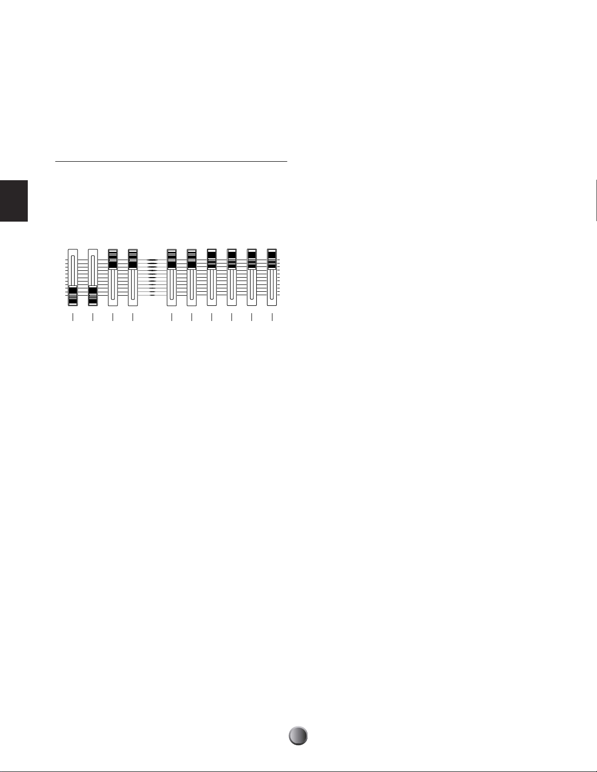
Slider Controls
DTXTREME IIs incorporates a simple but powerful mixer.
There are ten sliders on the top panel for adjusting the
volume balance, reverb effect, and the levels of the Individual
Outputs.
5 SNARE slider
Adjusts the output volume of the snare drum.
6 KICK slider
Adjusts the output volume of the bass drum.
Play Section
Adjusting the Volume Balance
The following sliders let you control the volume balance
between rhythm instruments in the drum kit, and control the
volume balance among the drum kit, accompaniment, and
click sounds. You can also adjust the output volume of the
stereo-mixed sounds independently for the OUTPUT jacks
and headphones.
MAX
MAIN OUT PHONES CLICK ACCOMP
1234 56789 )
MIN
SNARE KICK
1 MAIN OUT slider
Adjusts the output volume of the stereo-mixed sounds for the
OUTPUT (L/MONO & R) and DIGITAL OUT jacks.
2 PHONES slider
Adjusts the output volume of the stereo-mixed sounds for the
PHONES jack. The identical stereo signal can be adjusted
independently from the MAIN OUT slider 1.
TOM HI-HAT CYMBAL MISC
7 TOM slider
Adjusts the output volume of the toms.
8 HI-HAT slider
Adjusts the output volume of the hi-hat cymbals.
9 CYMBAL slider
Adjusts the output volume of other cymbals (ride, crash, etc.).
) MISC slider
Adjusts the output volume of rhythm sounds other than those
listed above.
n Each slider control on the top panel works like the fader on a mixer.
You can specifically adjust the volume of each accompaniment part
as song data (page 72), and the volume of each drum or percussion
sound as drum voice data (page 49). You can use the ACCOMP
and MISC sliders then to adjust the overall volume for the rest of
the parts, while maintaining the volume balance specified in the
song and drum kit.
3 CLICK slider
Adjusts the output volume of click sounds from the specified
output jack (page 81).
4 ACCOMP slider
Adjusts the output volume of the accompaniment parts (other
than MIDI channel 10) in the song. This allows you to adjust
the volume balance between the drum kit and
accompaniment parts when you play the drum kit along with
song playback.
26
Page 27
Adjusting the Reverb Effect
123456
MAX
MIN
ACCOMP
SNARE KICK
TOM HI-HAT CYMBAL MISC
SHIFT
Adjusting the Individual Output levels
You can control the amount of reverb (system effect) applied
to a rhythm instrument by moving the associated volume
slider while holding down the SHIFT button. The relevant
sliders must be set appropriately to control reverb beforehand
(page 75).
SHIFT
MAX
ACCOMP
MIN
SNARE KICK
TOM HI-HAT CYMBAL MISC
1234567
1 SHIFT button + ACCOMP/REVERB slider
Adjusts the master return level of the reverb effect.
2 SHIFT button + SNARE slider
Adjusts the reverb send level for the snare drum.
You can control the output level from INDIVIDUAL
OUTPUT (1 to 6) jacks by simultaneously holding down the
SHIFT button and moving the appropriate volume slider.
The relevant sliders must be set appropriately to control
individual output levels beforehand (page 53).
n Drum sounds routed to the Individual Outputs are excluded from
the stereo mix, and thus are not output from any of the stereo
outputs (PHONES, OUTPUT L&R, DIGITAL OUT).
Play Section
1 SHIFT button + SNARE slider
Adjusts the output level for INDIVIDUAL OUTPUT 1.
3 SHIFT button + KICK slider
Adjusts the reverb send level for the bass drum.
4 SHIFT button + TOM slider
Adjusts the reverb send level for the toms.
5 SHIFT button + HI-HAT slider
Adjusts the reverb send level for the hi-hat cymbals.
6 SHIFT button + CYMBAL slider
Adjusts the reverb send level for other cymbals (ride, crash,
etc.).
7 SHIFT button + MISC slider
Adjusts the reverb send level for rhythm sounds other than
those listed above.
n Keep in mind that the various settings described above are
interdependent; changing a setting may not have the expected
effect. For example, there may be little or no reverb sound if you set
too small a value for one of the drum voice reverb send level settings
(page 53), or if the master send or return level to the system reverb
(page 57) is set too low.
2 SHIFT button + KICK slider
Adjusts the output level for INDIVIDUAL OUTPUT 2.
3 SHIFT button + TOM slider
Adjusts the output level for INDIVIDUAL OUTPUT 3.
4 SHIFT button + HI-HAT slider
Adjusts the output level for INDIVIDUAL OUTPUT 4.
5 SHIFT button + CYMBAL slider
Adjusts the output level for INDIVIDUAL OUTPUT 5.
6 SHIFT button + MISC slider
Adjusts the output level for INDIVIDUAL OUTPUT 6.
n Since each drum instrument can be freely assigned to any output
(page 75), you can adjust the master output level for multiple
instruments with a single slider. For example, the CYMBAL slider
can become the master fader for all cymbals including hi-hats or
only for the snare drum, depending on their output settings.
27
Page 28
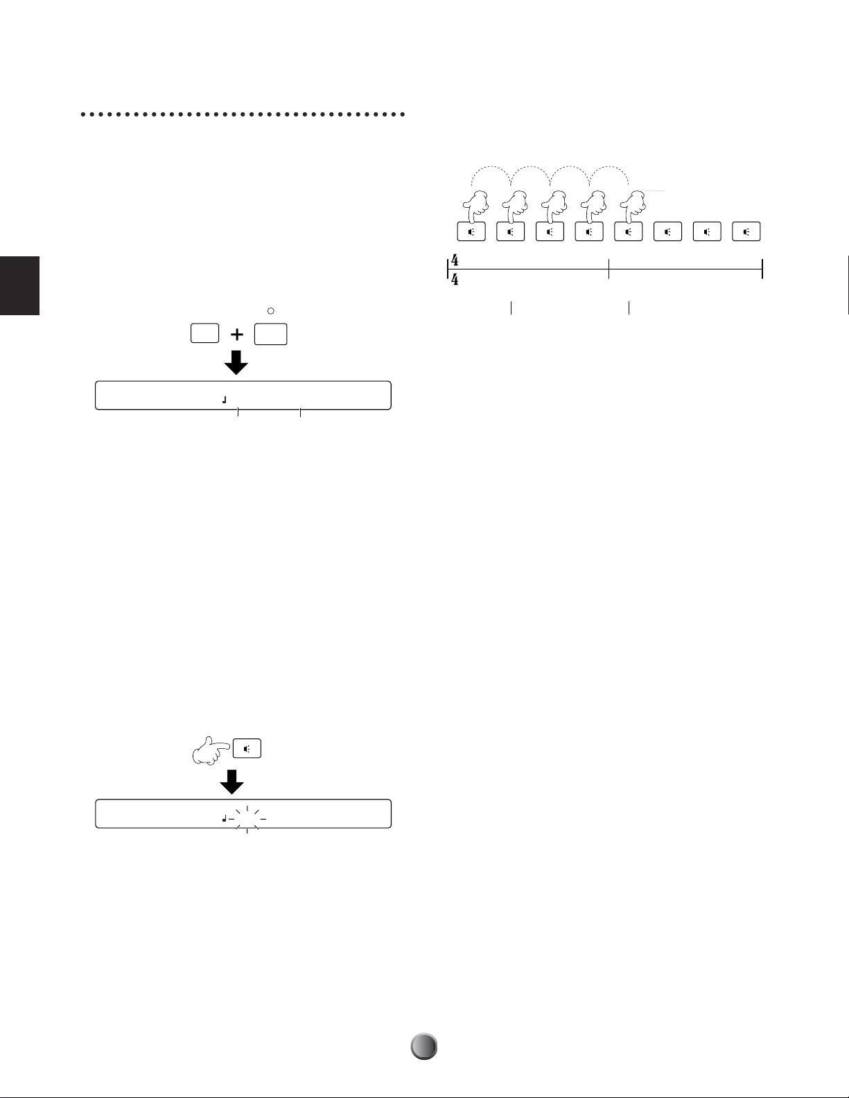
Tap Tempo Feature
1
2
(1)
Detection start
3
(2)
4
(3)
1
(4)
2
3
4
Hit at a steady tempo
Detection end
This convenient function lets you automatically set the tempo
by tapping out the beats on a pad or the Audition button.
This is especially useful when you want to intuitively set the
tempo by “feel” during song playback or click playback.
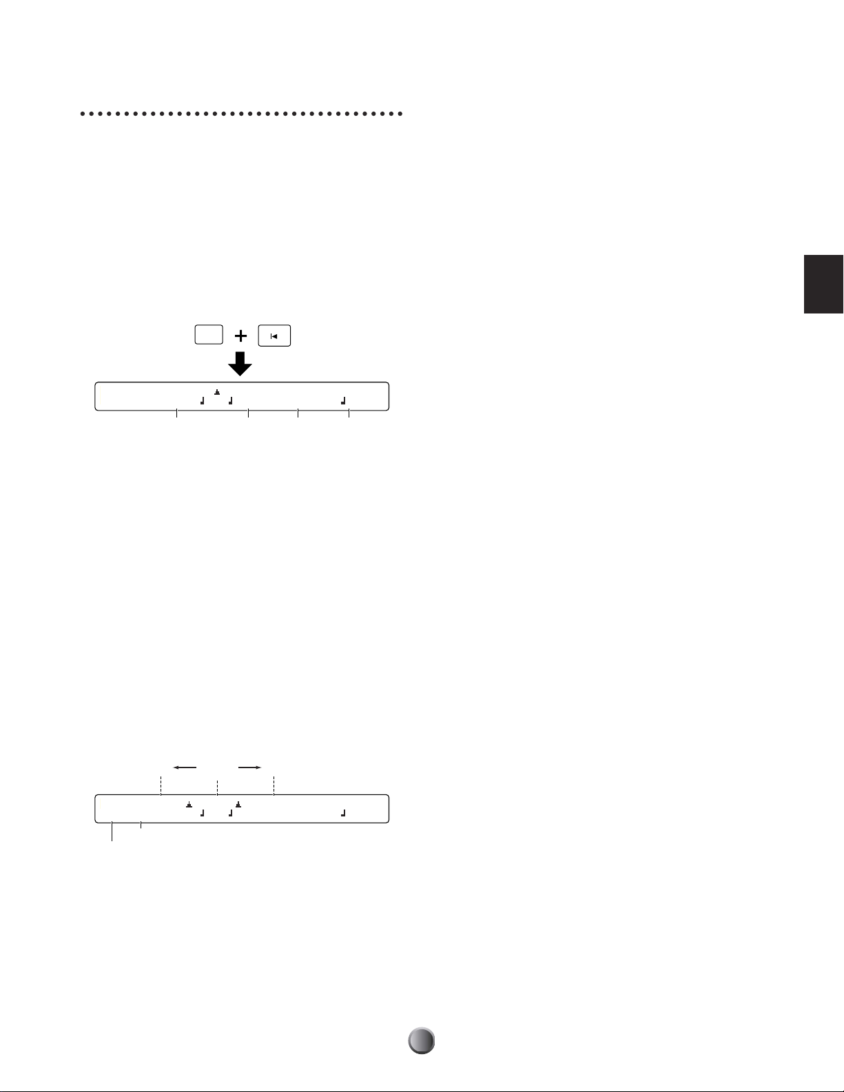
1. Open the Tap Tempo screen by simultaneously holding
down the SHIFT button and pressing the TAP (CLICK)
button. While using the Tap tempo feature, the current
tempo value is shown in the LED display.
Tempo detection is done between every other beat to the
1st beat of the next measure. In this way, if you continue
tapping, the tempo is determined on every 1st beat of the
measure in the 2nd pass and after.
Play Section
SHIFT
[TAP TEMPO] TEMPO BEAT
=138 4/4
Current tempo Current time signature
CLICK
TAP
2. Use the knob under the BEAT parameter to set the time
signature of a measure. The tempo will be detected for
one measure of the time signature specified here.
❏ Settings: 1/4~16/4, 1/8~16/8, 1/16~16/16
3. Count the beat by hitting a pad or the Audition button at
a steady tempo, for one measure.
If you set a tempo for a 4/4 measure, hit a pad 5 times to
count 1st to 4th beat, plus 1st beat of the next measure.
Similarly, for a 3/4 measure, hit 4 times to count 1st to
3rd beat, plus 1st beat of the next measure.
The tempo is detected from the timing at which you hit
the pad, and is shown in the LED display and indicated as
a TEMPO value (blinks) in the LCD screen.
n If you do not hit the pad for a certain period, the tempo count
is reset. In this case, start counting from scratch (hit 5 times for
a 4/4 measure).
4. Press the ENTER/YES button to apply the calculated
tempo. The TEMPO value will stop blinking and remain
lit.
5. Repeat steps 2 to 4 if you want to restart tempo detection.
6. Press the EXIT/NO button to finish the tempo setting
and return to the Play mode display.
n The Tap Tempo feature cannot be used during recording or in
recording standby.
[TAP TEMPO] TEMPO BEAT
=115 4/4
❏ Recognized Tempo Range: 30-300
28
Page 29
Groove Check Feature
When playing the drum kit or tapping the Audition button
along with a song or click, you can check how far off your
timing is. Specify the length of the note — this is used as the
basis for measuring the timing accuracy of your play, to a
resolution of 1/96 quarter note.
n The Groove Check feature functions only during playback of the
song or click.
1. Open the Groove Check display by simultaneously
holding down the SHIFT button and pressing the
GROOVE CHECK (Reset) button.
SHIFT
GROOVE CHECK
Timing difference for each hit: The difference in timing
accuracy each time you hit a pad or drum is displayed as a
number in the range of –48 to +48 (slower to faster).
A negative value means you are playing slower than the
song tempo, and a positive value means you are playing
faster. A value of zero means you are playing exactly on
time. This is useful to measure the timing tightness of a
specific instrument such as the snare or bass drum.
Average: The difference in timing accuracy is measured as
an average and displayed as a number in the range of –48
to +48 (slower to faster). A negative value means you are
playing slower than the song tempo, and a positive value
means you are playing faster. A value of zero means you
are playing exactly on time. This is useful for checking the
overall tightness of your drumming.
Play Section
[Groove]|------- -------| BEAT CLICK
0/ 0 Quant= =100 4/4 3
Quantization
Tempo
signature
Time
Metronome
2. Set the desired quantize resolution (expressed as a note
length) for the basis of the Groove Check timing. Possible
settings are same as the CLICK beat (page 23).
n You can check the accuracy of your phrase with complicated
subdivisions by setting a different note length from the CLICK
beat.
3. If necessary, set the TEMPO, BEAT and CLICK values as
in the default display (page 23).
4. Play the drum kit or hit the Audition button in time with
song playback or click count. The timing difference for
each hit is displayed both graphically and as a numerical
value.
Exactly
on time
FasterSlower
5. Press the EXIT/NO button to finish groove checking and
return to the Play mode display.
[Groove]|--- ---+-- ----| BEAT CLICK
- 9/+ 3 Quant= =100 4/4 3
Average
Timing difference for each hit
29
Page 30
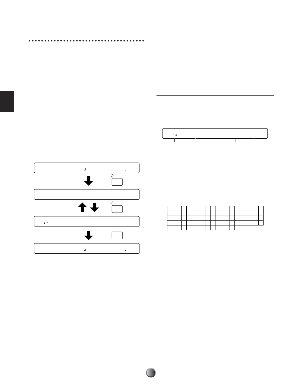
Play Section
[CHAIN]"IniChain" Step Type Num=U1
<GHIJK> 1 kit Initkit
1234
!"#$%&’ ( ) * , . / 0123
456789 : ; < >?@ABCDEFG
HIJKLMNOPQRSTUV XYZ [
¥]^_
` a bcde f gh i j k lmno
pqr s t uvwxyz{|}→←
=
W
+-
Chain Feature
A Chain is a series of drum kits and songs arranged in the
order you want. For example, you can arrange different drum
kits to be selected in a specific order — for example, to match
that of a set list in a live performance, or to use with a series of
practice songs arranged in order of difficulty.
The DTXTREME IIs can memorize up to 32 chains for
instant recall them whenever you want them.
Switching the Chain Display
When pressing the CHAIN button, the Chain Play display
appears first, allowing you to play existing chains. Pressing
the CHAIN button again calls up the Chain Edit display,
from which you can create a new chain or edit an existing
one. Every press of the CHAIN button toggles between these
two displays. When you finish using this feature, simply press
the EXIT/NO button to return to the default display.
KIT=P1 SONG=P1 TEMPO BEAT CLICK
Kit name Songname =107 4/4
Chain Play display
CHAIN=32 Step=01 Kit=U1 Kit Name
ChainNam
CHAIN
Creating or Editing a Chain
The first step in using chains is to create one. You can also
freely edit an existing chain at any time. Once you create or
edit a chain, you’ll need to store it BEFORE you start
working with another chain.
n Select a target chain in the Chain Play screen beforehand (page 32).
Chain Edit Screen
Here you can arrange drum kits or songs one by one to each
step in a chain. A chain can contain up to 32 steps, and you
can link a chain to another if you want a long chain that
exceeds 32 steps or a looped chain that repeats a specific series.
1 Chain Name
Enter the desired name for the current chain, using up to
eight characters. Use the leftmost knob to move the entry
position (cursor) for each character. Then, use the second-toleft knob to enter a character at that position. Repeat this step
and specify the chain name (maximum of eight characters).
❏ Available characters:
Chain Edit display
[CHAIN]"ChanName" Step Type Num=U1
<90abc> 32 kit kit name
KIT=P1 SONG=P1 TEMPO BEAT CLICK
Kit name Songname =107 4/4
CHAIN
EXITNOEXIT
NO
2 Step
Select a step number (1 to 32) to which a drum kit or song is
to be assigned. You can set up to 32 steps for a chain.
30
Page 31

3 Type
Store Current Chain to chain
10 My Chain
Store Current Chain to chain
Are You Sure ? [Yes/No]
Specify what you want to assign to the currently selected step
(in Step 2 above). Available settings are: drum kit (kit), song
(song), linking to another chain (jump), and end mark at this
step (END).
❏ Settings: song, kit, jump, END
n If you make a chain with a jump point on the way to the final step,
the chain will not play the steps after the jump point.
n If you specify neither jump or END within a chain, it will continue
playing to the 32nd step. To effectively use the chain, set jump or
END at the final step.
Procedure
Create or edit a chain referring to above explanations
concerning each item in the edit screen.
n In the Chain Edit screen, a dot appears in the LED display. This
means you have edited the chain but not yet stored it. If, while
editing, you switch to Chain Play display and select another chain,
your edits will be lost (the LED dot will go out). Be sure to save
necessary edits before selecting another chain.
1. Use the two left knobs to specify the chain name.
4 Num=
Specify the item according to the Type 3 setting made above.
Select a drum kit for kit, a song for song, or a destination
chain for jump. You can view the number in the upper row
and the name in the lower row. If you set the current chain
for the destination, you will have a looped chain. You do not
need set anything for END, since the display shows “---” (no
setting).
❏ Settings: When Type 3 is set to song: Preset or User song
When Type 3 is set to kit: Preset or User drum kit
When Type 3 is set to jump: 1~32 (chain)
n If you select a drum kit or a song on the memory card (C1-C99 for
each), you'll need the appropriate memory card containing the
relevant drum kit or song data for correct playback of the chain.
Otherwise, “No Card” is shown in the display.
2. Use the center knob to select a step, and then use the two
right knobs to set the type and number for the step.
3. Specify other steps in the same manner.
4. Press the STORE button to save this chain.
5. Use the second-to-right knob to select a chain number
(1 to 32), to which the current chain you’ve created or
edited will be stored.
6. Press the ENTER/YES button. A confirmation message
will appear in the display.
Play Section
7. Press the ENTER/YES button again to execute the store
operation, or press the EXIT/NO button to cancel.
8. When the chain is successfully stored, the display shows
“Done.” for a second and returns to the Chain Play
display. When the store operation is cancelled by using
the EXIT/NO button, you can continue editing if you
want.
31
Page 32

Playing a Chain
To play back a chain, simply turn the knob to select each step.
You can also select a step while playing the drum kit by
increasing/decreasing the step number with a pad (page 77) or
a foot switch (page 46).
Procedure
In addition to the panel knob, you can assign increment and
decrement functions respectively to two different switching
devices — pads (page 77), foot switches (page 46), or a
combination of pad and foot switch, making it possible to
select each step in the chain even while playing the drum kit.
Play Section
Chain Play Screen
Once you create a chain, play it from the Chain Play display.
CHAIN=1 Step=1 Kit=U1 Init Name
IniChain
1 CHAIN=
Select the desired chain.
❏ Settings: 1~32
2 Step=
Select a step number for the current chain 1, which calls up
the drum kit or song assigned to that step (the name and
number appears at the right).
Kit=xxx xxx, Song=xxx xxx.
❏ Settings: 1~32 (depending on each chain)
1. Use the leftmost knob to select the chain you want to use.
2. Use the left-to-second knob, pad, or foot switch to select a
step and recall a drum kit or song.
n If the selected step is a jump point, it calls up the drum kit or
song assigned to the first step of the linked chain.
3. Play the drum kit or song that is recalled.
4. As desired, select the next step in the same manner and
call up another drum kit or song for playing.
32
Page 33

Edit Section
DTXTREME IIs as Drum System
Because of their quick decay and non-pitched nature, drum and percussion instruments are ideal for electronic
music. Rhythm machines and samplers make it easy to use actual instrument sounds and assemble the rhythms in
authentic, dynamic ways. However, programming of drum sounds to realistically reproduce the natural energy,
feel, groove and dynamics of the original is very difficult to do. Most musicians feel that there is nothing like
“pounding out” the rhythm on a set of drums to get the proper quality of “comfortable randomness.” Hit and
sound, and repeat this to create a rhythm — this primitively simple process produces a very humanized
performance. Our research and development was focused on that point — a entirely new fusion of acoustic and
electronic instruments. The answer is DTXTREME IIs. Converting what a player intends to represent through
drumming into trigger signals, and linking them to MIDI, an industry standard for electronic musical instruments,
DTXTREME IIs enables a creative rhythm-oriented musical performance beyond what you can expect from
traditional acoustic drums.
From Trigger Input to Sound Output
Before getting deep inside the DTXTREME IIs system, let’s take a look at its mechanism, structure, and basic
ideas.
Edit Section
1 Trigger input using pad
Drum kit
Preset 1-59
User 1-20
2 Trigger settings
3 Voice settings
4 Effects settings
5 Sound output
13C#-1 96A#5
Settings for
external devices
P1
U40
Computer
or
MIDI device
Save
Memory card
Load
33
Page 34

Edit Section
1 Send trigger signals to the DTXTREME IIs by hitting drum pads (or drums attached with a trigger pickup) connected to the
trigger input jacks 1 to 16 and the HI-HAT CONTROL and FOOT SW jacks.
2 Set each trigger input properly so that DTXTREME IIs can receive the trigger signals, and also assign a specific function to
each trigger input. You can assign songs (pad song) or note numbers other than those of MIDI channel 10 (rhythm and drum
part) for a variety of performances.
3 Assign a drum voice to each note number of MIDI channel 10 (rhythm and drum part) so that you can play a drum voice by
hitting a drum pad. You can also specify how each drum voice will sound (volume, pan, etc.) in the kit. Optionally, you can
activate MIDI settings for other parts when you choose the drum kit.
4 Set system effects applied to the entire drum kit, and insertion effects applied to specific drum voices.
5 Sound out drum and other voices as audio signals, according to the above settings 2 to 4.
The above settings 2 to 4 in combination are referred to as a drum kit — just as is indicated on the panel, with the three
buttons TRIGGER, VOICE, and EFFECT outlined by DRUMKIT. When you press one of these buttons, you can start editing
that part of the current drum kit. Your drum kits can be stored as up to 40 User kits (U1 to U40) in the DTXTREME IIs
memory, or up to 99 User kits (C1 to C99) to an external memory card.
34
Page 35

Memory, Buffer, and
To save the current drum kit data, execute the store operation
by pressing the STORE button.
Store Operation
When editing a drum kit, you need to be aware of the
relationship between the storage memory and the working
buffer. Every time you select (recall) a Preset kit or a User kit
from the DTXTREME IIs internal memory or an external
memory card, the drum kit data is copied to the working
buffer.
Internal memory
External
Preset kit
(ROM)
n Because of the working buffer, you can select and edit any drum kit
memory
card
even when it is a Preset kit (read-only data). When creating your
original drum kit, first select an existing Preset or User kit, edit it,
and then store as a new User kit.
Drum kit data in the buffer will be used for everything — for
your performance or for editing. Once you edit any data
(change the data from its stored status), the rightmost dot in
the LED display will light.
n The LED display may show the current tempo (page 76).
If you select another drum kit at this point, the dot will go
out. This means other drum kit data is newly copied to the
working buffer, overwriting the drum data you were working
with. If you wish to save what you edited, make sure to do so
BEFORE selecting another drum kit.
2. Copy to buffer
User kit
(RAM)
1. Select a kit
Dot lit
Working buffer
3. Editing/Playing
DRUMTRIGGERMODULE
STORE
Store Current Drumkit to Kit
C001 Initkit
When the above screen is shown, select the destination User
kit number (U1 to U40, or C1 to C99) where your current
data is stored. You do not need to select a new destination if
you edit an existing User kit and overwrite it with edited data.
However, if you edit one of Preset kits (P1 to P90) and want
to store a new drum kit, you need to specify a User kit
number in the internal memory (U1 to U40) or on the
memory card (C1 to C99). After selecting the destination,
press the ENTER/YES button. The following confirmation
message will appear in the display.
ENTER
ENTER
YES
YES
Store Current Drumkit to Kit
Are You Sure ? [Yes/No]
n If you select C1 to C99 with no memory card inserted to the CARD
slot, “No Card” will be shown and the store operation cannot be
continued. Insert a proper memory card (page 85) or store the data
to internal memory.
Press the ENTER/YES button again to execute the store
operation. When complete, “Done.” will be shown briefly.
Press the EXIT/NO button to cancel the operation. In either
case, the display will return to the default Play mode screen.
Note that the dot in the LED display goes out after you
execute the store operation.
You can store the current drum kit any time during editing.
Save your edits often — frequent updates ensure that your
important data is maintained.
Edit Section
35
Page 36

Tr igger Settings
[FootCtl1] Func Sens
HiHat 16
[FootCtl2] HHInput MIDI Type
IN8 10ch Ctl 4
[FootSw1] Func Velocity MIDI Type
HiHat 111 10ch Ctl127
[FootSw2]OnValue OffValue
127 127
[COMMON1] Volume WaveDir
127 No card
[COMMON2] Song Tempo 9to10 11to12
P1 200 off off
[KitName] Name "Acoustic"
<90abc>
[TrgSens1] Type Gain Curve PadCtrl
Input=1 RHP 32 3 - pitch
Press the TRIGGER button on the top panel, designated by
DRUMKIT, to start editing trigger settings for the drum kit
you are working with.
n Trigger settings are the most important part for your drum kit to
sound various voices properly. If necessary, first copy existing trigger
settings (page 44) from a Preset kit that are similar to what you
want, then edit them for your original kit.
TRIGGER
[TrgSens1] Type Gain Curve PadCtrl
Input=1 RHP 32 3 - pitch
Edit Section
n The first page that appears (the one last called up) may be different
from the display shown above (page 76).
Edit Pages and Basic Operations
Trigger settings are available in the following seventeen pages,
categorized by purpose and function.
Page name
[TrgSens1] Type Gain Curve PadCtrl
Input=1 RHP 32 3 - pitch
[TrgSens2] Level(100%) Velocity(127)
Input=16 20% to 100% 32 to 127
[TrgSens3] SelfRej Rej Spec Rej
Input=16 6ms 4 9 from IN16
[TrgFunc] Func Song Repeat Mode
Input=16 padsong P1 off cutoff
[TrgMIDI1] Mode TrgAltG RimVel
Input=16 stkmono 16 --------
[TrgMIDI2] Note Note# GateTime Channel
Input=16 4th *88 E5 0.3s 10
In the first seven pages you can set up each trigger input on
the DTXTREME IIs rear panel. This means you actually
have seven pages for each of the sixteen inputs. However, you
can easily switch to other inputs by turning the leftmost knob,
while staying in the same page. This is also useful for
comparing settings of the current input with others.
n You can also select the target input by hitting the corresponding pad
(page 76), which is more convenient if you make fine tuning
settings of your drum kit while playing.
Also, refer to “Basic Operations” on page 20.
[TrgMIDI3] Note VelXFade
Input=16 1st 1
[TrgCopy1]Input Kit Input
from 16 to current 16
[TrgCopy2]Copy Current Trigger to Kit
U1
[MIDI EG] Curve Time MIDI Type
3 - 32 10ch Ctl 16
36
Page 37

[TrgSens1] & [TrgSens2] Trigger Basics
TP120SD/
TP100
Rim 1
Rim 2
TP65S
Rim 1 Rim 2
These two pages contain settings to set how your playing
strength (trigger signal level) is converted into velocity for
MIDI Note On events. In general, hitting the pad hard
produces a large velocity value, and the resulting voices sound
loudly.
[TrgSens1] Type Gain Curve PadCtrl
Input=1 RHP 32 3 - pitch
14532
[TrgSens2] Level(100%) Velocity(127)
Input=16 20% to 100% 32 to 127
67
1 Input=
Select a target trigger input (1 to 16).
2 Type
Select the pad type for the target input 1. The list below
shows the pad types that can be set for the connected pads or
trigger pickups.
❏ Settings: Refer to the following table.
DTXTREME IIs Pad Types
KP KP65/60/80S/80
TP-1/Snr TP120SD/100 (*1)
TP-1/Tom TP120SD/100 (*1)
TP-2/Snr TP65S (*1)
TP-2/Tom TP65S (*1)
TP-3 TP80S/80/65/60 (*2)
RHP RHP120SD/120/100/80
RHP Kick KP120
PCY-1 PCY150S
PCY-2 PCY130S/130/65S/65/80S/80
PCY-3 PCY80S/80/65S/65/60/10
RHH RHH130 (*3)
BP BP80
DT Snare DT10/20 drum trigger for snare drum
DT HiTom DT10/20 drum trigger for high toms
DT LoTom DT10/20 drum trigger for low toms
DT Kick DT10/20 drum trigger for bass drum
TRG Snr Generic trigger pickup for snare drum
TRG HTom Generic trigger pickup for high toms
TRG LTom Generic trigger pickup for low toms
TRG Kick Generic trigger pickup for bass drum
*1 “TP-1/Snr” and “TP-2/Snr” set more sensitivity to the rim 2 for easy
closed rimshot play.
“TP-1/Tom” and “TP-2/Tom” set the same sensitivity to both rims 1
and 2.
*2 “TP-3” will produce a voice assigned to the rim 1 when the pad rim is
hit.
*3 “RHH” also supports the TP65S pad.
3 Gain
Set the input gain for the pad type 2. The larger the value,
the more sensitive the pad becomes.
❏ Settings: 0~63
4 Curve
Set the velocity curve for the change of trigger signal levels.
For larger values, the pad must be hit harder to produce the
loudest sound.
❏ Settings: 1~5
5 PadCtl
When using a TP120SD or TP100 pad for the snare drum or
tom (connected to trigger inputs 1 to 6), you can use the pad
controller to adjust the drum tone. Specify a voice parameter
(page 48) adjusted by the pad controller. Select a value that
ends with an “R” letter, for simultaneous control for both pad
and rim 1 voices.
❏ Settings: off (no effect), pitch (R) (Tuning), volume (R), voice
(R), pan (R), layer (R), filter (R), Q (R), attack (R),
decay (R), decay R+ (see note), wave 1 (Layer 1 voice)*,
wave 2*, XSfilter*, XSdecay*, balance*
* Controllable when Type=XtrSnr is selected in voice settings.
n The decay+R value can continuously adjust the voice decay rate and
switch to another specific voice (strainer-off tone for the snare
drum, for example) at a minimum setting.
n You can select any parameter here, but actual effect by the pad
controller depends on the drum voice selected in the voice settings.
Edit Section
37
Page 38

Edit Section
Velocity
Velocity
curve 1-5
1
5
127
001
99%12%
127
064
001
99%50%
0-49%
No sound is output
1
5
Velocity
Velocity
curve 1-5
6 Level
Set the range of trigger levels for the target input 1, as
minimum and maximum values. Trigger levels within the
specified range are accordingly converted into velocity values.
If the trigger signal is below the minimum level, no sound is
output. If the trigger signal exceeds the maximum level, it
will be converted into the maximum velocity, specified with
the Velocity 7 parameter. When you hit the pad, the trigger
level is displayed as a percentage to the right of Level.
❏ Settings: Minimum level: 0~99, Maximum level: 1~100
7 Velocity
Set the range of velocity values that corresponds to the Level
range 6, as minimum and maximum values. The drum
voice will sound in the specified velocity range. When you hit
the pad, the converted velocity value is displayed to the right
of Velocity.
❏ Settings: Minimum velocity: 0~126, Maximum velocity: 1~127
n Setting a high minimum velocity will produce a loud sound when
you hit the pad lightly. However, this will narrow the dynamic
range and reduce the amount of expressive control you have over the
volume change.
Relationship between Trigger
Level and Velocity
Ex. 1
In this illustration, velocity values are output for
trigger levels between 12% and 99%. For a trigger
level of 12%, the velocity is 001. For a trigger level of
99%, the velocity is 127.
Ex. 2
In this illustration, velocity values are output for
trigger levels between 50% and 99%. For a trigger
level of 50%, the velocity is 064. For a trigger level of
99%, the velocity is 127. No sound is produced
(velocity value of zero) for trigger levels between 0%
and 49%.
n This “trigger level to velocity” conversion is also applied to
the rim velocity (velocity output from the pad rim; page
41). When you use a pad rim for cymbal muting, the
trigger level generated by holding the rim will be converted
to a velocity value of zero.
38
Page 39

[TrgSens3] Rejection
[TrgFunc] Func Song Repeat Mode
Input=16 padsong P1 off cutoff
21453
[TrgFunc] Trigger Function
This page contains three different settings to prevent “false
hits” — such as double triggering caused by stick rebound, or
crosstalk caused by pad vibration or interference between
trigger inputs. Trigger signals detected as such false hits do
not produce any sounds.
[TrgSens3] SelfRej Rej Spec Rej
Input=16 6ms 4 9 from IN16
1
2
34
1 Input=
Select a target trigger input (1 to 16).
2 SelfRej
Use this to avoid double triggering caused by the target input
1 itself, produced by stick rebound. If there are 2 trigger
signals is generated at the input 1 within the specified period
here, the second signal is detected as double triggering.
❏ Settings: 5ms (milliseconds) ~10.0s (seconds)
3 Rej
Use this to avoid crosstalk caused by vibrations while playing
the drum kit. If a trigger signal is generated at the target
input 1 and its level is lower than specified here, that trigger
signal is detected as crosstalk.
❏ Settings: 0 (no rejection) ~9
4 Spec Rej
Use this to avoid crosstalk caused when hitting a specific
(interfering) pad. If a trigger signal at the target input 1 is
generated with a level lower than specified here, after the
trigger signal at the interfering input specified here, the trigger
signal at the input 1 is detected as crosstalk.
❏ Settings: Level: 0 (no rejection) ~9, Input: IN1~IN16
n Use the two right knobs for setting the level and interfering trigger
input.
Besides triggering a drum voice, drum pads connected to the
trigger inputs can be used for various controls. Since this
control function can also be assigned to the pad rim, you can
play the head of the pad normally while using the rim to
control a parameter or function. Keep in mind that a pad rim
or head that is assigned to a control function cannot also be
used to trigger a drum sound.
1 Input=
Select a target trigger input (1 to 16). For trigger inputs 1 to
8, you can select from two rims (1R1, 1R2, ..., 8R1, 8R2).
n Rim settings are effective with a dual trigger pad. In the Pad-to-
Input Matching Chart (page 16), for combinations indicated by “A
(Best)” or “B (Good),” you can use up to two rims. You cannot use
the pad rim for “C (Fair)” combinations.
2 Func
Select the function of the target input 1. This specifies what
you can trigger by hitting the drum pad or rim.
❏ Settings:
• normal: Plays a drum voice and outputs MIDI events.
• padsong: Controls a pad song. Specify a song with the
parameters 3~5.
• click: Enables or disables the click.
• inc: Increment — selects the next drum kit in the Play mode
display, or selects the next step in the Chain Play display.
• dec: Decrement — selects the previous drum kit in the Play
mode display, or selects the previous step in the Chain Play
display.
•bypass: Temporarily disables trigger inputs other than the target
input 1 (page 37).
• strt/stp: Controls playback of the main song (same as Start/Stop
in the transport control).
• MIDI EG: Outputs Control Change data continuously (page
44).
Edit Section
39
Page 40

Edit Section
[TrgMIDI1] Mode TrgAltG RimVel
Input=16 stkmono 16 --------
1432
Setting a Pad Song
You can play up to four pad songs from one drum kit. If you
have already specified four pad songs for other trigger inputs,
the following parameters 3~5 cannot be set and “---” is
shown in the display.
3 Song
Select a song for the pad song. You cannot choose a song
from the memory card.
❏ Settings: Preset or User song
4 Repeat
Enable or disable repeated playback of the pad song.
❏ Settings: on (enabled), off (disabled)
5 Mode
Specify how you want the pad song to play back.
❏ Settings:
• play: Song playback will start or stop each time you hit the pad.
Song will always play from the beginning.
• chase: Each time you hit the pad, the song will play one measure
and automatically stop. If you hit the pad during playback, the
song will resume playback from the next measure.
• cutoff: Song playback will start or stop each time you hit the
pad. If you start a different pad song during playback, the
current song will stop.
n When you play multiple songs (main song and pad songs) with one
drum kit, keep in mind the MIDI channel assignments for those
songs. You may get unexpected and confusing results if different
data in two or more songs share the same MIDI channel.
[TrgMIDI1] Key On Mode
In this page you can specify how MIDI Note On events will
be triggered when a pad is hit. Triggering by hitting a pad can
be associated with pressing a key on the keyboard, and a
triggered note will sound according to a specific rule. This
rule is called the Key On mode.
1 Input=
Select a target trigger input (1 to 16). For trigger inputs 1 to
8, you can select from two rims (1R1, 1R2, ..., 8R1, 8R2).
n Rim settings are effective with a dual trigger pad. In the Pad-to-
Input Matching Chart (page 16), for combinations indicated by “A
(Best)” or “B (Good),” you can use up to two rims. You cannot use
the pad rim for “C (Fair)” combinations.
2 Mode
Specify the Key On mode for note numbers (page 42)
assigned to the target input 1.
Each of the trigger inputs 1 to 16 (except for rims) can be
assigned to play up to six notes simultaneously (stack mode),
or up to nine different notes played in turns (alternate mode).
Each of these has two different modes, mono and multi. In
mono mode, previously triggered notes will be muted by
newly triggered ones.
❏ Settings for other than rims (R1 and R2):
• stack: Stack & multi mode.
• alter: Alternate & multi mode.
• stkmono: Stack & mono mode.
• altmono: Alternate & mono mode.
• hold: A variation of stack & mono mode, letting notes triggered
by hitting the pad continue sounding until you hit it a second
time.
n If you only trigger a drum voice by hitting a pad, and do not play
either a chord (stacked notes) or a phrase (alternate notes), select a
multi mode (stack or alter) here. If you select a mono mode, it will
cut off notes triggered continuously, producing unnatural sounds.
There are three Key On modes for rims: Single mode, which
is suitable for closed rimshots (cross sticking); hold mode,
which is for sounding a rim voice as long as you want; and
withpad mode, which is suitable for open rimshots.
❏ Settings for rims (R1 and R2 only):
• single: Plays a drum voice assigned to the rim of the target input
1.
• hold: A variation of single mode, letting a rim voice triggered by
hitting the rim continue sounding until you hit it again.
• withpad: Simultaneously plays a drum voice (and other stacked
or alternate notes) and a rim voice for the target input 1 each
time you hit the rim.
40
Page 41

n Withpad mode does not demand that you play a real open rimshot
[TrgMIDI2] Note Note# GateTime Channel
Input=16 4th *88 E5 0.3s 10
14532
(hitting the pad rim and head at the same time). It lets you play
both the pad and rim sounds by only hitting the rim.
3 TrgAltG
Specify the trigger alternate group number to which the target
input 1 belongs. If multiple trigger inputs are grouped with
the same number assigned, only one input from that group is
enabled at a time. As a result, hitting a pad from that group
will mute notes triggered by other pads in the same group.
This is useful to prevent an unnecessary stacking of notes.
❏ Settings: off (not grouped, default), 1~32
n This function works in conjunction with the RvKeyOff setting
(page 52) for a drum voice associated with the trigger input (by
MIDI note number). When a trigger input is enabled from a trigger
alternate group, other trigger inputs from the same group
respectively generate a MIDI note off event for the corresponding
MIDI note number. This note off event is then sent to the internal
tone generator and is used to mute a drum voice assigned to that
MIDI note number. If this voice is set to receive the Note Off event
(RvKeyOff=on), you can successfully mute its sound by the trigger
alternate group setting. Otherwise (RvKeyOff=off), you cannot
mute it even though the Note Off event is generated and sent to the
tone generator.
4 RimVel
This parameter is available only when a rim (1R1 to 8R2) is
selected for the target input 1, and determines how to
output the rim velocity. The “trigger level to velocity”
conversion (page 37) for the target input 1 is applied to all
settings other than the fix settings.
❏ Settings:
• mute hi: Outputs a velocity value according to how hard you hit
the rim. When you hit (hold) the rim with strength below a
certain level, a velocity value of zero is output and produces the
muting effect. Select this if you connect a cymbal pad to the
target input 1.
• mute lo: Same as mute hi, but the muting sensitivity is lowered.
If you cannot easily get the muting effect with mute hi, select
this setting.
• variable: Outputs a velocity value according to how hard you hit
the rim. Select this if you connect a drum pad to the target input
1.
• fix1~fix127: Outputs a fixed velocity value regardless of how
hard you hit the pad. However, you cannot use the muting
effect with one of these fixed values.
n If you connect and specify an RHP-series real head pad to the target
input 1, mute hi or mute lo for the rim velocity 4 will be shown
in brackets. This means the trigger input and the pad type do not
match, therefore the muting effect is disabled.
[TrgMIDI2] Note On Event
After you’ve specified how the trigger signal is converted into
a velocity value (page 38), and how to produce a triggered
sound (page 40), now go on to this page and specify the note
for that sound with its pitch and length (note number and
gate time), as well as the MIDI channel assignment. This
determines a specific MIDI Note On event (consisting of
channel, note number, and velocity) output when you hit a
pad. Again, in this page, you can specify up to nine notes
(including the basic note for a drum voice) according to the
specified Key On mode, up to two notes for rims, and an
optional note for muting respectively, by note number, gate
time, and MIDI channel.
Edit Section
1 Input=
Select a target trigger input (1 to 16).
2 Note
Select a target note (1st to 9th for an alternate mode, 1st to
6th for the stack mode), rim notes (rim1, rim2), or a mute
note.
When selecting the trigger input 1 for hi-hats (page 45), five
notes are available for hi-hats instead of the 1st to 9th notes:
• open: For an open hi-hat sound by hitting the pad.
• clse: For a closed hi-hat sound by hitting the pad.
• fcls: For a foot-closed hi-hat sound.
• spls: For a foot-splashed hi-hat sound.
• clsRim: For a rim sound by hitting the pad while the hi-hat
pedal is depressed.
• opRim1: For a rim1 sound by hitting the pad while the hihat pedal is released.
• opRim2: For a rim2 sound by hitting the pad while the hihat pedal is released.
n The mute note setting is a powerful performance feature that lets
you mute the sound played by the pad, simply by touching/hitting
the edge or rim. More than that, it also lets you play a second
sound. For example, you could perform a cymbal “choke” by
grabbing the edge of a cymbal pad — and at the same time have a
reverse cymbal or other sound play.
41
Page 42

Edit Section
240
MIDI note number
C036C148C260C372C484C596C6
108 127
C7
[Chord] ChordName
C Maj7
Root Type
SHIFT
3 Note#
Assign a note number for the note 2 of the target input 1.
Since the note number is shown with its note name (key and
octave), both will change accordingly as you turn the
associated knob. Also refer to the column below for more
about the note number.
❏ Settings:
• off: Use this as end mark for the phrase. If you play a six-note
phrase by setting to an alternate mode, set the 7th note to off.
This enables you repeat the phrase by continuously hitting the
pad. For stack modes, this setting has no effect.
• note number: Note numbers below 13 (C#-1) or above 94
(A#5) are shown in brackets. This means they will be output as
MIDI events, but will not play sounds from the built-in tone
generator.
• skip: Available only for alternate modes. Use this as a rest mark
for the phrase. This enables you play a phrase containing rests
by repeatedly hitting the pad.
n An asterisk (*) displayed to the left of a note number means that the
same note number for MIDI channel 10 has been assigned
elsewhere, warning you that the same drum voice would be
triggered from multiple pads. For your information, copying trigger
settings from a Preset kit (page 44) ensures that the 1st note for each
trigger input will sound a proper drum voice (e.g., bass drum for
KICK, etc.).
4 GateTime
Set a gate time (note length) for the note number 3 to match
the note length with the drumming or main song tempo, or
to naturally sound a phrase containing rests. For the note on
the channel 10 5 (drum voice), its note length is determined
in conjunction with the voice settings (page 52).
❏ Settings: 0.0s~9.9s (in 0.1s increments), =1st
n For triggering a chord (multiple notes in a stack mode), you can
easily set the same gate time to all notes. Set any necessary gate time
to the 1st note, then set the same value to the rest of the notes.
5 Channel
Set a MIDI channel for the note number 3. This channel
will be used for both transmission and reception. You can use
this channel for playing the built-in tone generator from an
external MIDI controller, as well as sending the Note On
event to an external sound module by hitting the pad.
❏ Settings: 1~16, =1st (same as GateTime, convenient for triggering
a chord or a phrase)
Setting the Note Numbers
MIDI note numbers are used to specify the pitch of a
sound. Middle C, for example, is note number 60. In
general, each note is indicated by its name and octave,
such as C3 for middle C. So the note an octave above
C3 is C4, and the note number is 72.
This standardization makes things easier when playing
notes on an external sound module.
You can easily set multiple note numbers for a chord
or a phrase in the [TrgMIDI2] page (only available in
this screen).
Using a Chord Name
To call up the following page, simultaneously hold
down the SHIFT button and press the Rewind
button.
Use the second-to-left and center knobs to specify a
chord by its root and type. Also, you can
automatically set the chord to the current trigger
input, using up to five note numbers.
❏ Settings:
• Root: C, C#, D, D#, E, F, F#, G, G#, A, A#, B
• Type: Maj7, Maj, 6th, m7(11), Maj9, add9, min, min6,
min7, m7(b5), mM7, min9, madd9, 7th, 7(#5), 7(b9),
7th9, 7(#9), 7(#11), 7(b13), 7(13), 7sus4, sus4, dim, aug
After you’ve selected a chord, press the ENTER/YES
button. An “Are You Sure?” confirmation message will
appear in the display. Press the ENTER/YES button
again to actually set the note numbers. Press the
EXIT/NO button to cancel the operation. When you
return to the previous page, try hitting the pad. You
can play the chord in a stack mode, or arpeggio in an
alternate mode.
42
Page 43

Using an External MIDI Keyboard
You can assign a note or multiple notes such as a chord
using an external MIDI keyboard connected to MIDI
IN on the rear panel. Select the 1st note 2 and then
play the desired chord on the MIDI keyboard. The
chord you play is automatically divided and
programmed into individual numbered notes in
played order (1st to 6th for stack modes, 1st to 9th for
alternate modes).
n If you select a note other than 1st, only the first note (of a
chord) you play will be assigned to that note.
2 Note
Select a target note (1st to 6th).
❏ Settings: 1st, 2nd, 3rd, 4th, 5th, 6th
n You can select other notes, but cannot set the velocity crossfade
value 3 when “----” is shown.
3 VelXFade
Set a velocity curve (volume curve) for the note 2, to the pad
playing strength (softly to hard). For example, you could set
Curve 2 to the 1st note and Curve 3 to the 2nd. In this case,
the 1st note will sound louder when you play more softly, and
2nd note will sound louder when you play harder.
Viewing the Current Assignments
Press the SHIFT and TRIGGER buttons
simultaneously to call up the following page,
SHIFT
I=10 1.C#-2 2.D-1 3.E0 4.--- 5.--altm 6.--- 7.--- 8.--- 9.--- m.E#0
TRIGGER
Use the leftmost knob to specify the trigger input.
Now you can view the Key mode setting (page 38)
under the specified input, and note numbers for "1" to
"9" and "m" (1st to 9th, mute) positions, by its name
and octave.
[TrgMIDI3] Velocity Crossfade
We’ve seen earlier how to convert the trigger signal into a
specific velocity value, and you can guess that setting when
applied to chords results in each note of the chord sounding
with the same volume. In this page, you can set a velocity
crossfade curve for each note triggered, applying a kind of
natural randomness to the velocity of the notes in the chord.
Volume
1st
2nd
0
Velocity
❏ Settings: 1~10
12
Volume
0
34
Volume
0
56
Volume
0
78
Volume
Velocity
Velocity
Velocity
Volume
0
Volume
0
Volume
0
Volume
Velocity
Velocity
Velocity
Edit Section
[TrgMIDI3] Note VelXFade
Input=16 1st 1
132
n For above reasons, settings in this page are enabled when the trigger
input is set to the stack mode (page 40). In the alternate mode, each
note can be triggered in turn with a different velocity value.
1 Input=
Select a target trigger input (1 to 16).
0
910
Volume
0
Velocity
Velocity
0
Volume
0
43
Velocity
Velocity
Page 44

[TrgCopy1] & [TrgCopy2] Trigger Copy
[MIDIEG] MIDI Envelope Generator
Edit Section
You can copy trigger settings to create a drum kit for a similar
configuration of pads. Use the [TrgCopy1] page to copy
settings from a specific trigger input. Use the [TrgCopy2]
page to copy setting from the drum kit you are currently
working (editing) with. Either copy operation is done simply
by selecting a target and pressing the ENTER/YES button.
Copying from a Trigger Input
[TrgCopy1]Input Kit Input
from 16 to current 16
132
1 (from) Input
Select the source trigger input.
❏ Settings: 1~16
2 (to) Kit
Select the destination drum kit. Select current when copying
to the current drum kit.
❏ Settings: current, U1~U40
3 (to) Input
Select the destination trigger input of the drum kit 2.
❏ Settings: 1~16
Copying from the Current Drum Kit
[TrgCopy2]Copy Current Trigger to Kit
U1
1
1 (to) Kit
Select the destination drum kit.
❏ Settings: U1~U40
In this page, you can create a MIDI-controlled EG, triggered
from a pad head or rim (page 39). This is a function that
outputs the specified Control Change data values
continuously and controls them transitionally in an envelope
curve. You can use this, for example, for real-time control of
the stereo panning or volume level of sustained sounds from
an external synthesizer or the built-in tone generator.
[MIDIEG] Curve Time MIDI Type
3 -- 32 1ch Ctl 16
1342
Example: Curve 3
Control Change value
0
Time
1 Curve
Select from 8 different envelope curves. As shown in the
diagram above, different Control Change values will be
output in a transition time 2 in the envelope curve specified
here.
❏ Settings: 1~8
2 Time
Determines the transition time when the envelope curve 1
comes into effect. The larger the value, the longer the elapsed
time.
❏ Settings: 0~127
3 MIDI
Determines the MIDI channel used to output the Control
Change data.
❏ Settings: 1ch~16ch
Copy Operation
When you select the source and destination, press the
ENTER/YES button. An “Are You Sure?” confirmation
message will appear in the display. Press the ENTER/YES
button again to actually execute the copy operation. Press the
EXIT/NO button to cancel. When you return to the copy
page, continue copying if desired, or resume making trigger
settings.
4 Type
Determines the Controller number used to output the
Control Change data.
❏ Settings: Ctl0~Ctl119
n For more information on available controller numbers, refer to the
Controller Number List in the separate Data List.
44
Page 45

[FootCtrl1] & [FootCtrl2]
HH Controller Function
These two pages let you specify the function of a hi-hat
controller (Yamaha HH series), connected to the HI-HAT
CONTROL jack on the rear panel.
[FootCtl1] Func Sens
HiHat 16
12
[FootCtl2] HHInput MIDI Type
IN8 10ch Ctl 4
354
n You may not have hi-hat sounds or lose control of them if you
inadvertently change parameter values in these two pages, when
using normal hi-hat settings of the hi-hat pad to the trigger input 8
(HI-HAT).
1 Func
Set the hi-hat controller function.
❏ Settings:
• HiHatSP: Used as hi-hat controller. You can control tone
changes of your drum kit by applying pressure on the pedal
(default).
• HiHat: Used only as hi-hat controller.
• MIDI: Used only as MIDI continuous controller.
4 MIDI
Set the MIDI channel to output MIDI data 5 from the
hi-hat controller. The default is channel 10 for the drum kit.
❏ Settings: 1ch~16ch (default: 10ch)
5 Type
Set the type of MIDI data output from the hi-hat controller.
❏ Settings:
• Ctl0~Ctl119: Controller number (default: 4)
• A/T: Aftertouch
• P/B up: Pitch Bend Up
• P/Bdwn: Pitch Bend Down
n For more information on available controller numbers, refer to the
Controller Number List in the separate Data List.
Edit Section
2 Sens
Adjust the sensitivity of the hi-hat controller. The larger the
value, the greater the sensitivity of the controller.
❏ Settings: 0~63
3 HHInput
Select the trigger input that connects the hi-hat pad. This
setting internally links the hi-hat controller and the hi-hat pad
when you select HiHatSP or HiHat 1 for the controller
function. If you select none here, trigger inputs 1 to 16 will
become identical in trigger settings (page 40) — this drum kit
will not have hi-hats. In addition, you can use a foot switch
for hi-hat control (page 46).
❏ Settings: none, IN1~IN16 (default: IN8)
n Normally, the trigger input 8 is used for hi-hats (as designated on
the rear panel). This parameter lets you specify any trigger input
(1 to 16) for hi-hats if you want to create a custom drum kit
completely from scratch.
45
Page 46

Edit Section
[FootSw1] & [FootSw2]
Foot Switch Function
These two pages let you specify the function of a foot switch
(Yamaha FC4 or FC5) that is connected to the FOOT SW
jack on the rear panel.
[FootSw1] Func Velocity MIDI Type
HiHat 111 ---- ------
1432
[FootSw2]OnValue OffValue
127 127
56
1 Func
Select the foot switch function.
❏ Settings:
• HiHat: Acts as a hi-hat controller (switching between open and
closed sounds). Make sure to set an appropriate velocity value
2 when selecting this.
• click: Enables or disables the click.
• inc: Increment — selects the next drum kit in the Play mode
display, or selects the next step in the Chain Play display.
• dec: Decrement — selects the previous drum kit in the Play
mode display, or selects the previous step in the Chain Play
display.
• bypass: Temporarily disables trigger inputs (page 76).
• SStop: Controls playback of the main song (same as Start/Stop
in the transport control).
• MIDI: Outputs Control Change data. Make sure to set the
related detailed parameters 3~6 when selecting this.
• HH➝BD: Generates a trigger signal for trigger input 9 (KICK)
when the foot switch is pressed. Make sure to set an appropriate
velocity value 2 when selecting this.
4 Type
Determines the Controller number output from the foot
switch when MIDI is selected for the function 1.
❏ Settings: Ctl0~Ctl119 (controller number)
n For more information on available controller numbers, refer to the
Controller Number List in the separate Data List.
5 OnValue
Determines the control value output when pressing the foot
switch, when MIDI is selected for the function 1.
❏ Settings: 0~127
6 OffValue
Determines the control value output when releasing the foot
switch, when MIDI is selected for the function 1.
❏ Settings: 0~127
2 Velocity
Determines the velocity value output from the foot switch
when HiHat or HH➝BD is selected for the function 1.
❏ Settings: 1~127
3 MIDI
Determines the MIDI channel for the Control Change data
4 output from the foot switch when MIDI is selected for the
function 1.
❏ Settings: 1ch~16ch
46
Page 47

[COMMON1] & [COMMON2]
Kit Common Settings
These two pages let you make basic settings for the drum kit
you are currently working (editing) with. For this reason,
some parameters are not directly related to trigger settings.
[COMMON1] Volume WaveDir
127 No Card
12
5 9to10
If you set this parameter to on, trigger signals generated at
trigger input 9 (KICK) will be shared with trigger input 10.
Then, set trigger input 10 to play notes in an alternate mode
(for example, from a footswitch; no pad required). When you
play the bass drum in this case, you can have the phrase
automatically synchronized to a bass drum pattern assigned to
input 9.
❏ Settings: off, on
[COMMON2] Song Tempo 9to10 11to12
P1 off off off
3654
1 Volume
Determines the overall volume of the rhythm part including
the drum kit (MIDI channel 10).
❏ Settings: 0~127
n This is the same as the volume setting for MIDI channel 10 (page
54).
2 WaveDir
This determines the directory on the memory card (page 86),
where wave samples or user voice data used together with this
drum kit are stored. The next time you select this drum kit,
those files will automatically be loaded. Make sure to insert
the appropriate memory card into the CARD slot; otherwise,
“No card” will be shown.
❏ Settings: Directory name on a memory card
3 Song
This determines the song that is automatically called up when
you select this drum kit. Specify off to disable the automatic
selection of a song.
❏ Settings: off, Preset or User song
4 Tempo
This determines the tempo that is automatically set when you
select this drum kit. Specify off to disable the automatic
tempo setting.
❏ Settings: off, 30~300
6 11to12
If you set this parameter to on, trigger signals generated at
trigger input 11 will be shared with trigger input 12. (This is
used in the same way as 5 above.)
❏ Settings: off, on
n Trigger inputs 9/10 and 11/12 jacks are stereo pairs. However, you
can use them as four separate mono inputs if you connect four
mono pads using two Y-shaped cables and setting the above two
parameters 5 & 6 to off.
[KitName] Drum Kit Name
You can enter a name of up to 8 characters for the drum kit
you are now editing.
[KitName] Name "Acoustic"
<90abc>
Use the second-to-left knob to move the entry position
(cursor) for each character. Then, use the center knob to
enter a character at that position. Repeat this step and specify
the drum kit name (maximum of eight characters).
❏ Available characters:
!"#$%&’ ( ) * , . / 0123
456789 : ; < >?@ABCDEFG
HIJKLMNOPQRSTUV XYZ [
¥]^_
pqr s t uvwxyz{|}
` a bcde f gh i j k lmno
+-
=
W
→←
Edit Section
47
Once you’ve finished making the desired trigger
settings, store this drum kit (page 35).
Page 48

Voice Settings
Press the VOICE button on the top panel, designated by
DRUMKIT, to start editing voice settings for the drum kit
you are currently working with.
VOICE
In the first six pages you can assign a drum voice for each note
number contained in the rhythm and drum part (MIDI
channel 10) and set up how that voice will sound. Turn the
leftmost knob, and note the huge amount of target note
numbers available — 82 in all (13~94). This is the total of
usable notes for the rhythm and drum part, and provides
more than enough to choose from in setting up a simple kit.
You may also need to make adjustments to a Preset kit to suit
you’re applications, but such settings are always minimal. In
the rest of the pages, you can copy settings and make setups
for other MIDI parts for playing together with a drum kit.
Edit Section
[Voice1] Type Voice 42* Volume Tuning
38 D1 AcSnr1 MCA55 110 - 1.00
n The first page that appears (the one last called up) may be different
from the display shown above (page 76).
Edit Pages and Basic Operations
Voice settings are available in the following ten pages,
categorized by purpose and function.
[Voice1] Type Voice 2* Volume Tuning
49C#2 XtrSnr rim 127 + 0.00
Wave1 Wave2 XSfilter XSdecay Balance
Mapl1370 warm type1 32 0
[Voice3] Pan Layer Filter Q
49C#2 R13 +63 +63 +63
[Voice4] Attack Decay
49C#2 0 0
[Voice5] KeyMode AltGrp RvKeyOn RvKeyOff
49C#2 semi2 127 off off
Settings changes
[Voice1] Type Voice 2* Volume Tuning
49C#2 XtrSnr rim 127 + 0.00
n You can also select the target input by hitting the corresponding pad
(page 76), conveniently letting you fine-tune your drum kit settings
while playing.
Also, refer to Basic Operations on page 20.
[Voice6] Output RevSend ChoSend
49C#2 stereo 127 127
[VoiceCopy] Note Kit Note
from 49C#2 to current 49C#2
[MIDI1] Transmit PC# BankMSB BankLSB
Ch=10 off 001 000 000
[MIDI2] Volume Pan Ctrl# / Value
Ch=10 127 R63 127 127
[MIDI3] RevSend ChoSend
Ch=10 127 127
48
Page 49

[Voice1] Voice Basics
This page lets you assign a basic drum voice and adjust its
output volume and pitch. Voices are categorized by types so
that you can choose them easily, while viewing the
information about the voice such as whether it is two-layered,
looped, and so on.
4 Volume
Determines the output volume of the specified voice 3.
By specifically adjusting the volume for each voice, you can
balance the various instruments in the drum kit.
❏ Settings: 0~127
[Voice1] Type Voice 2* Volume Tuning
49C#2 XtrSnr rim 127 + 0.00
12345
1 Note Number & Name
Determines the target note number (13~94: C#-1~A#5).
Each note number is shown with a specific note name.
2 Type
Determines the voice category. You can select a voice 3 from
the category specified here. Select Wave if you want to load a
wave sample or audio file from a memory card. Select XtrSnr
if you want an extra snare drum that can be customized in the
next screen.
❏ Settings: AcKick, ElKick, AcSnr1~2, EleSnr, OtrSnr, XtrSnr,
AcTom1~3, EleTom, Cymbal, HiHat, Percs1~2,
Efect1~3, Loop, Voice, Melody, Wave, UsrVce
n UsrVce is a voice created using external System Exclusive parameter
change data. Such voices cannot be created on the DTXTREME
IIs itself, and explanations of how to use System Exclusive here are
outside the scope of this manual.
5 Tuning
Adjusts the pitch of the specified voice 3 by approximately
one cent (1/100 semitone).
❏ Settings: –24.00~+24.00
Edit Section
3 Voice
Determines the voice from the specified category 2.
Your selection will be shown with a number in the upper row
and name in the lower row. A two-layered voice is indicated
by an asterisk (*) at the end of its number. A voice shown
with a mark at the end of its name is looped, which you
can play repeatedly with a single shot (page 52). Press the
Audition button while holding down the SHIFT button to
stop looped playback during audition.
❏ Settings: For more information on each voice, refer to the Voice
List in the separate Data List.
n If you always use a specific pad only to trigger an external sound, set
NoAssign to that pad (note number) 3. However, if you normally
play a voice 3 from the built-in tone generator, and sometimes
replace it with an external sound, it is more convenient to
temporarily mute the internal voice by disabling a specific Note On
event sent to the built-in tone generator (page 80), which saves you
the trouble of re-assigning NoAssign every time you need to replace
a sound.
49
Page 50

Edit Section
Setting an Extra Snare Drum
Extra Snare is a special snare drum voice that you can
select when you specify XtrSnr for the voice category.
Moreover, you can customize the snare drum using the
following parameters. (These cannot be set with other
voices, and “----” is shown in the display.)
Wave1 Wave2 XSfilter XSdecay Balance
Mapl1370 warm type1 32 0
14532
Special snare drum is a two-layered composite voice,
which is created by combining two different drum
voices, adjusting the volume balance between these
voices, and modifying the composite voice tone using
the Filter and Decay parameters. If you use a
TP120SD or TP100 pad for the snare drum, you can
also use the pad controller to dynamically adjust one
of the following parameters for a dynamic tone change
(page 37).
[Voice3] Pan & Tone
This page lets you adjust the stereo panning and filter of the
voice assigned to the note number. If you selected a twolayered voice, you can also specify the volume balance
between the layers.
[Voice3] Pan Layer Filter Q
49C#2 R13 +63 +63 +63
14532
1 Note Number & Name
Determines a target note number (13~94: C#-1~A#5). Each
note number is shown with a specific note name.
2 Pan
Determines the pan setting for the voice assigned to the note
number 1. This setting determines the stereo position of the
voice.
❏ Settings: L64~C~R63 (left to center to right)
1 Wave1
Select a drum voice for the layer 1.
❏ Settings: Mapl1370, MCAbs55, MCVint55, Beech55,
Maple55, Alumin55, Brass35, Brass55, Brass65,
Steel65, Bamboo, FRPSnr
2 Wave2
Select a drum voice for the layer 2.
❏ Settings: warm, crisp, cool, short, punchy, BS, silky, bright,
old, VOX1, VOX2, VOX3, roll, trash
3 XSfilter
Specifies the filter effect.
❏ Settings: thru (no effect), type1, type2
4 XSdecay
Adjusts the duration of your snare drum.
❏ Settings: off (no effect), 1~32
5 Balance
Adjusts the volume balance between the layer 1 and 2
sounds.
❏ Settings: –64~0~+63
3 Layer
Specify the volume balance between layers if you selected a
two-layered voice for the note number 1. If the voice is not
two-layered, the parameter cannot be set and “---” is shown in
the display.
❏ Settings: –64~0~+63 (100:0~50:50~0:100)
4 Filter
Determines the filter setting for the voice assigned to the note
number 1. This is a low-pass filter that cuts the frequencies
higher than the cutoff point specified here and passes the rest,
as shown in the diagram below.
❏ Settings: –64~+63
5 Q
Adjust the Q (bandwidth) factor for the filter 4. Boosting
the frequencies around the cutoff point as shown in the
diagram below makes the filter peak sharper and more
pronounced.
❏ Settings: –64~+63
Low-pass filter and frequencies
Level
Level
Q (Q curves)
Q max.
Q min.
50
Frequencies
passed by the filter
FrequencyCutoff point
Blocked frequencies
Frequency
Page 51

[Voice4] Envelope
[Voice5] Polyphony
This page lets you adjust the volume envelope of the voice
assigned to the note number. Every musical instrument has a
unique volume envelope that helps distinguish what kind of
instrument it is. For drum or percussion instruments, their
unique characteristics come from the attack and decay rates
(speeds) in the volume envelope. Adjusting these two factors
lets you create a variety of tonal nuances in the voice.
[Voice4] Attack Decay
49C#2 0 0
132
Level
Peak
DecayAttack
Time
1 Note Number & Name
Determines a target note number (13~94: C#-1~A#5). Each
note number is shown with a specific note name.
2 Attack
Determines the attack rate of the current voice. The larger
the positive value, the faster the attack rate. The larger the
negative value, the slower the attack rate. Keep in mind that
if the voice originally has a fast attack rate, specifying higher
values cannot make the rate faster past a certain point.
❏ Settings: –64~+63 (slower to faster)
3 Decay
Determines the decay rate of the current voice. The larger the
negative value, the slower the decay rate. The larger the
positive value, the faster the decay rate. If you want a cymbal
with a long release, set its decay rate to a large negative value.
A large positive value may cause the sound to cut off
unnaturally.
❏ Settings: –64~+63 (slower to faster)
This page lets you set how many polyphonic voices are
allowed for the specified note number. The built-in tone
generator can play up to 64 polyphonic notes at a time.
However, there may be times when this may not be enough
— particularly if you play along with many parts in a song or
play the drum kit with a large number of short notes. You can
prevent this by limiting the polyphony for each drum voice.
[Voice5] KeyMode AltGrp RvKeyOn RvKeyOff
49C#2 semi2 125 off off
14532
1 Note Number & Name
Determines a target note number (13~94: C#-1~A#5). Each
note number is shown with a specific note name.
2 KeyMode
Determines how the same voice is played in response to
multiple notes.
❏ Settings:
• poly: No limitation until the DTXTREME IIs tone generator
reaches maximum polyphony.
• semi8: Up to eight polyphonic notes — every initial note will be
muted to play the 9th note.
• semi4: Up to four polyphonic notes — every initial note will be
muted to play the 5th note.
• semi3: Up to three polyphonic notes — every initial note will be
muted to play the 4th note.
• semi2: Up to two polyphonic notes — every initial note will be
muted to play the 3rd note.
• mono: Only a single note — each note will be muted by the
subsequently played note.
• himono: Same as mono, but excluded from the last-note
priority rule — notes are never muted by other notes.
n If a note number (drum pad) is set to mono and assigned with a
voice with a long release (such as cymbal), hitting that pad
continuously will cut off the previous sound unnaturally. However,
setting every note number to poly to prevent this situation is not a
good idea, since this may “steal” polyphony from other important
parts.
Edit Section
51
Page 52

Edit Section
3 AltGrp
You can put multiple note numbers 1 in a specific alternate
group. By including several note numbers in the same
numbered group here, prevents them from playing
simultaneously. For realistic hi-hat sounds using several
voices, assign HHpedal to the foot-closed voice and HHpad
to other hi-hat voices triggered by the hi-hat pad and rims.
This enables the foot-closed sound to mute any other hi-hat
sounds when depressing the hi-hat pedal controller (HHpedal
has priority over HHpad).
❏ Settings: off (not grouped), HHpedal, HHpad, 1~125 (group
number)
n Only a single note can play at a time from one alternate group, in
the last-note priority manner.
4 RvKeyOn
Determines whether the built-in tone generator receives Note
On events for the note number 1. This is useful when you
want to output them from MIDI OUT on the rear panel,
without routing to the built-in tone generator, for the purpose
of triggering only external sounds. Set this to on if you want
to play voices from the built-in tone generator.
❏ Settings: off, on
5 RvKeyOff
Determines whether the built-in tone generator receives Note
Off events for the note number 1. Set this to off if you want
to ensure that a cymbal voice or a one-shot wave sample plays
to its full duration.
❏ Settings: off, on
Using Note Off with Looped Voices
Most drum voices are one-shot samples and
automatically stop playing at the end of the wave data
without receiving a Note Off event (RvKeyOff = off).
If you set these voices to receive Note Off events
(RvKeyOff = on), adjust the gate time (page 42)
properly to match their release time, otherwise
playback of the sound will be cut off in the middle.
On the other hand, the built-in tone generator also
features looped voices, and these need to be set for
receiving Note Off events (RvKeyOff = on), otherwise
they will not stop playback. Because of this, Note Off
is crucial to effectively using looped voices. To
properly use a looped voice, set its note number to
generate Note Off events (RvKeyOff = on) in
conjunction with the gate time setting. For example,
you can hit the pad every second measure to play a
looped voice endlessly if the gate time is adjusted to
match two measures in the performance tempo. You
may also need to limit its polyphony to a single note
(KeyMode = mono).
Voice portion longer than
the specified gate time
will play with RvKeyOff=off
One-shot voice
Looped voice
One phrase
Gate time
RvKeyOff=on
52
Page 53

[Voice6] Output Routing
[VoiceCopy] Voice Copy
This page lets you set an output routing for the voice assigned
to the note number. Though your basic options are one of
the INDIVIDUAL OUTPUT (1 to 6) jacks for parallel
output or a pair of OUTPUT jacks for stereo output, you can
use them for more variations in conjunction with effect
settings (page 55).
[Voice6] Output RevSend ChoSend
49C#2 stereo 127 127
1432
1 Note Number & Name
Determines a target note number (13~94: C#-1~A#5). Each
note number is shown with a specific note name.
2 Output
Determines the output for the voice assigned to the note
number 1. When routed to an Individual Output, the voice
cannot be monitored using headphones.
❏ Settings:
• stereo: Routed to OUTPUT (L/MONO and R).
• InsFx1, InsFx2: Routed to the specified insertion effect (1 or 2).
You cannot select these when the Localizer is enabled.
• thru: Routed to OUTPUT (L/MONO and R) bypassing the
Localizer. You can select this only when the Localizer is enabled.
• IND1&2, 3&4, 5&6: Routed to the specified pair of Individual
Outputs (in stereo).
• IND1, 2, ... 6: Routed to the specified Individual Output (in
mono).
n If you select either insertion effect (InsFX1 or InsFX2), the final
output is determined by the insertion effect settings.
You can copy voice settings for a specific note number (MIDI
channel 10) to the drum kit you are editing, letting you set up
an editing template for creating drum kits with similar
settings.
[VoiceCopy] Note Kit Note
from 49C#2 to current 49C#2
132
1 (from) Note
Determines the source note name (of the current drum kit).
❏ Settings: 13C#-1~94A#5
2 (to) Kit
Determines the destination drum kit. Select current when
copying to the current drum kit.
❏ Settings: current, U1~U40
3 (to) Note
Determines the destination note name of the drum kit 2.
❏ Settings: 13C#-1~94A#5
Copy Operation
After selecting the source and destination, press the ENTER/
YES button. An “Are You Sure?” confirmation message
appears in the display. Press the ENTER/YES button again to
actually execute the copy operation. Press the EXIT/NO
button to cancel. When you return to the copy page,
continue copying if desired, or resume making voice settings.
Edit Section
3 RevSend
Determines the send level to the reverb effect (system effect)
for the voice assigned to the note number 1.
❏ Settings: 0~127
4 ChoSend
Determines the send level to the chorus effect (system effect)
for the voice assigned to the note number 1.
❏ Settings: 0~127
n Actual amounts of the reverb and chorus effects for each drum voice
are determined by the master send levels for the entire drum kit
(page 58).
53
Page 54

Edit Section
[MIDI1], [MIDI2] & [MIDI3] MIDI Setup
Use these three pages to make settings for a MIDI ensemble
using the built-in tone generator or external sound modules.
The setting data will be sent to MIDI parts internally or
externally (via MIDI OUT or USB) when you recall and play
the drum kit you are currently editing.
[MIDI1] Transmit PC# BankMSB BankLSB
Ch=10 on 001 000 000
1432
[MIDI2] Volume Pan Ctrl# / Value
Ch=10 127 R63 127 127
765
[MIDI3] RevSend ChoSend
Ch=10 127 127
98
1 Ch=
Determines the target MIDI channel (1 to 16).
2 Transmit
Determines the MIDI events that will be sent out over the
target channel 1.
❏ Settings:
• off: Sends no MIDI events. All following parameters cannot be
set and “---” is shown in the display.
• all: Sends both Program Change and Control Change, and all
following parameters become accessible.
• PC: Sends only Program Change, and parameters related to
Program Change become accessible. Parameters related to
Control Change (in the 2nd and 3rd screens) are disabled.
n When sending and setting only Program Change (Transmit=PC),
you can also use Bank Select (a Control Change event).
3 PC#
Determines the program number to be transmitted. If used
for the built-in tone generator, this specifies a GM voice.
❏ Settings: 001~128
n If you set a program number for channel 10 (Ch = 10), it will be
only sent out externally via MIDI OUT or USB. Since it is not sent
to the built-in tone generator, your drum kit will not be affected.
4 BankMSB & BankLSB
If you use an external sound module that has multiple sound
banks, you can use these two events for selecting a bank. In
combination with the program number parameter 3, you
can select a specific sound program. However, you do not
need to use these two events for the built-in tone generator
since it has no banks.
❏ Settings: 000~127 (for both MSB and LSB)
5 Volume
Determines the value for the controller number 007
(volume). If used for the built-in tone generator, this affects
the volume of each part.
❏ Settings: 000~127
6 Pan
Determines the value for the controller number 010 (pan).
If used for the built-in tone generator, this affects the stereo
panning of each part.
❏ Settings: 000~064~127 (left to center to right)
7 Ctrl# & Value
Control Change is MIDI information used to control the
performance of a MIDI device. You can control a variety of
functions pre-defined as controller numbers and their control
values. These two parameters let you create a specific Control
Change event by setting the controller number (Ctrl#) and
control value (Value).
❏ Settings: ---, 000~127 (Ctrl#), 000~127 (Value)
n Selecting “---” for Ctrl# will automatically set “---” for Value,
disabling this feature.
8 RevSend
Determines the value for the controller number 091 (effect
depth). If used for the built-in tone generator, this specifies
the master send level to the reverb effect (system effect) for
each part.
❏ Settings: 000~127
9 ChoSend
Determines the value for the controller number 093 (effect
depth). If used for the built-in tone generator, this specifies
the master send level to the chorus effect (system effect) for
each part.
❏ Settings: 000~127
n If you set a Control Change event 7 that duplicates the Volume 5,
Pan 6, RevSend 8, or ChoSend 9 setting, the Control Change
event 7 will take priority.
Once you’ve finished making the desired voice
settings, store this drum kit (page 35).
54
Page 55

Effect Settings
DTXTREME IIs provides reverb and chorus as system
effects, as well as two different insertion effects, and a threedimensional Localizer effect.
Reverb
This system effect includes 12 reverb types that let you
recreate the ambience of a performance space — from a small
room to a large concert hall. In the voice settings (page 53),
you can specify the amount of reverb applied to each drum
voice in the drum kit. This is useful, for example, if you want
more reverb for the snare drum, but less for the bass drum.
Chorus
This system effect includes 13 chorus types of soft to hard
modulations (chorus, flanger, jet effect, and so on). In the
voice settings (page 53), you can specify the amount of chorus
applied to each drum voice in the drum kit. This is useful, for
example, if you want unique flanging sounds for hi-hats and
other cymbals.
Sound Mixing that Fully
Utilizes Effects
Slider controls on the top panel let you easily mix the
instrument sounds of the DTXTREME IIs. However,
you can also create more complex and more flexible
mixing schemes in conjunction with the output
routing for each drum voice (page 53) and effect
settings explained here. First, take a look at the
following diagram. It shows possible output routings
for each drum voice with several parameter settings.
Drum Voice Output
stereoInsFX1InsFX2IND
Thru
onon
Localizer
Cho
Send
Rev
Send
Ins FX2
ThruonThru
Ins FX1
off
Chorus
Edit Section
Insertion Effects 1 and 2
These additional effects give you tools to further enhance the
sound — or even completely change the sonic character of a
voice. Each effect block has a wide variety of 44 types
(chorus, flanger, distortion, wah, etc.). These two insertion
effects are arranged in parallel so that you can selectively apply
the effects to specific drum voices in your drum kit.
Localizer
This effect is optimized for headphone monitoring and
creates a realistic 3D sound image of your drum kit — placing
each instrument in a specific “virtual” space in the 3D
ambience, so that each sound appears to come from a
different direction. This 3D effect can be specified separately
for your drum kit and other instruments in the song, and
gives you the feeling of playing drums in a realistic ensemble.
This 3D effect is intended for headphones and cannot be
heard well if played from normal speakers.
n Both insertion effects and the system chorus effect are automatically
disabled when the Localizer effect is active.
Reverb
Individual
Output
Stereo
Output
Stereo
Phones
The actual effect settings include the output routing
after drum voices are applied with an effect, and this is
closely associated with the output setting of each drum
voice. In other words, specifying the output of a drum
voice also determines which effect can be applied to
that voice. In the left part of the diagram, you can see
four basic output options — stereo, InsFX1, InsFX2,
IND — provided for each drum voice. Also, thru is
added to the options when you enable the Localizer.
55
(Continued to next page)
Page 56

Edit Section
(Continued from previous page)
4 Completely Separate Effects
If you specifically set the output of each drum voice,
system effects and two insertion effects can be used as
four completely separate effects. Here is a example of
applying four different effects to four separate drum
voices and sending the signals to the stereo OUTPUT
jacks:
Settings in the [Voice6] page...
•For drum voice 1: Output = stereo, RevSend = (other
than zero), ChoSend = 0
•For drum voice 2: Output = stereo, RevSend = 0,
ChoSend = (other than zero)
•For drum voice 3: Output = InsFX1
•For drum voice 4: Output = InsFX2
Effect settings:
•In the [Effect] page (master send levels to system reverb
and chorus effects): Localizer = off, RevSend = (other
than zero), ChoSend = (other than zero)
•In the [Reverb] page (master return level from system
reverb effect): RevRetrn = (other than zero)
•In the [Chorus] page (master return level from system
chorus effect): Cho➝Rev = 0, ChoRetrn = (other than
zero)
•In the [InsFX] pages: Type = (other than THRU) for FX
= 1, and RevSend = 0 (zero), ChoSend = 0, Output =
stereo
•In the [InsFX] pages: Type = (other than THRU) for FX
= 2, and RevSend = 0, ChoSend = 0, Output = stereo
If you make four one-on-one routes (from voice to
effect) and select a different effect (also different from
system reverb and chorus effects) for each insertion
effect, you can output each drum voice in stereo, each
with a different effect applied.
Effect settings:
•In the [Effect] page (master send levels to system reverb
and chorus effects): Localizer = off, RevSend = (other
than zero), ChoSend = (other than zero)
•In the [Reverb] page (master return level from system
reverb effect): RevRetrn = (other than zero)
•In the [Chorus] page (master return level from system
chorus effect): Cho➝Rev = (any value), ChoRetrn =
(other than zero)
•In the [InsFX] pages: Type = 2BandEQ for FX = 1, and
RevSend = 0, ChoSend = 0, Output = IND1
•In the [InsFX] pages: Type = COMP for FX = 2, and
RevSend = 0, ChoSend = 0, Output = IND2
With these settings, you can obtain the following
results. Note that you can even count and use the
stereo OUTPUT jacks as a pair of INDIVIDUAL
OUTPUT jacks.
•Snare drum: Mono output from INDIVIDUAL
OUTPUT 1 without system reverb and chorus effects,
after processing with two-band equalizer from insertion
effect 1.
•Bass drum: Mono output from INDIVIDUAL
OUTPUT 2, after processing with compressor from
insertion effect 2.
•Toms 1 and 2: Stereo output from INDIVIDUAL
OUTPUT 3 and 4 without any effects applied.
•Toms 3 and 4: Stereo output from INDIVIDUAL
OUTPUT 5 and 6 without any effects applied.
•Cymbals: Stereo output from OUTPUT (L/MONO and
R) with system reverb and chorus effects applied.
In these examples, the output signal routing and effect
settings are closely associated. Try out other signal
routings for your specific applications and
requirements.
Parallel Outputs with Effects
You can easily send a drum voice to the
INDIVIDUAL OUTPUT jacks if you set Output to
IND (in stereo pair or mono) in the voice settings.
However, these settings only allow dry outputs of
drum voices without any effects applied. You can also
utilize insertion effects for parallel outputs of drum
voices while applying your favorite effects.
Settings in the [Voice6] page...
•Output = InsFX1 — for snare drum
•Output = InsFX2 — for bass drum
•Output = IND3&4 — for tom 1
•Output = IND3&4 — for tom 2
•Output = IND5&6 — for tom 3
•Output = IND5&6 — for tom 4
•Output = stereo, RevSend = (any value), ChoSend = (any
value) — for cymbals
56
Page 57

[Effect] Effect Basics
[Reverb] System Reverb Effect
Press the EFFECT button on the top panel, designated by
DRUMKIT, to start editing effect settings for the drum kit
you are currently working with.
EFFECT
Category Parameter
[Effect]Localizer RevSend ChoSend
off 40 40
123
n The first page that appears (the one last called up) may be different
from the display shown above (page 76).
1 Localizer
Enable (on) or disable (off) the Localizer.
❏ Settings: on, off
n When the Localizer is enabled, you can use only the system reverb
effect for other effects. Since you cannot use system chorus and
insertion effects, their respective edit pages will not appear. If the
Localizer is disabled, its edit pages will not appear instead.
Configure the system reverb effect. This setting data will be
sent to the built-in tone generator when you recall and play
the drum kit you are currently editing. This setting data is
shared not only with each drum voice (MIDI channel 10),
but also with all other parts from the built-in tone generator.
[Reverb] Type Time Diffusion InitDlay
HALL1 2.1 10 12.7
1
1 Type
Select a reverb type. For system reverb, you can choose from
the following 12 types. Select NONE if you want to
temporarily disable the system reverb.
❏ Settings: NONE, HALL1~2, ROOM1~3, STAGE1~2, PLATE,
WHITEROOM, TUNNEL, CANYON, BASEMENT
For detailed explanations of the other parameters, refer to the
Effect Type List in the separate Data List. Note that the same
parameter name may not always represent an identical
function.
n System reverb effect offers a single reverb effect specified here to all
parts from the built-in tone generator. Use an insertion effect if you
want to apply a different reverb effect to a drum voice.
Edit Section
2 RevSend
Determines the send level to the system reverb effect for the
entire drum kit. This works as a master level to reverb send
levels for the drum voices (page 53).
❏ Settings: 0~127
3 ChoSend
Determines the send level to the system chorus effect for the
entire drum kit. This works as a master level to chorus send
levels for the drum voices (page 53).
❏ Settings: --- (disabled when the Localizer is enabled), 0~127
n RevSend 2 and ChoSend 3 only work for rhythm part (MIDI
channel 10) from the built-in tone generator. These are equivalent
to the reverb send and chorus send levels (page 54) available when
transmission to MIDI channel 10 is enabled.
57
Page 58

[Chorus] System Chorus Effect
[InsFX] Insertion Effects
Edit Section
Configure the system chorus effect. This setting data will be
sent to the built-in tone generator when you recall and play
the drum kit you are currently editing. This setting data is
shared not only with each drum voice (MIDI channel 10),
but also with all other parts from the built-in tone generator.
[Chorus] Type LFO Depth FBLeval
CHORUS1 0.25Hz 54 +13
1
n You cannot configure the system chorus effect when the Localizer is
enabled (page 57).
1 Type
Select a chorus type. For system chorus, you can choose from
the following 14 types. Select NONE if you want to
temporarily disable the system chorus.
❏ Settings: NONE, CHORUS1~4, CELESTE1~4,
FLANGER1~3, SYMPHNIC, ENSEMBLE, PHASER
For detailed explanation for any other parameters, refer to the
Effect Type List in the separate Data List. Note that the same
parameter name may not always suggest an identical function.
n System chorus effect offers a single chorus effect specified here to all
parts from the built-in tone generator. Use an insertion effect if you
want to apply a different chorus effect to a drum voice.
Configure each of 2 insertion effects. Besides the system
effects, you can use these to apply a variety of effects to drum
voices, or to make an advanced internal mix by DTXTREME
IIs itself.
[InsFX] Type Dry/Wet L>RDlay R>LDlay
FX=1 CrossDlay (D=W) 170.0 170.0
12
n You cannot configure the system chorus effect when the Localizer is
enabled (page 57).
1 FX=
Select the target insertion effect (1 or 2) using the leftmost
knob.
❏ Settings: 1, 2
2 Type
Select an effect type to assign. You can assign any of 44 types
for each insertion effect.
❏ Settings: THRU, HALL1~2, ROOM1~3, STAGE1~2, PLATE,
DelayLCR, DelayLR, ECHO, CrossDlay,
KARAOKE1~3, CHORUS1~4, CELESTE1~4,
FLANGER1~3, SYMPHONIC, ENSEMBLE,
ROTARY, TREMOLO, AUTOPAN, PHASER,
DISTORTION, OVERDRIVE, AMPSIM, 3BandEQ,
2BandEQ, FILTER, AUTOWAH, TOUCHWAH1~2,
ENHANCER, COMP, NOISEGATE
For detailed explanations of the other parameters, refer to the
Effect Type List in the separate Data List. Note that the same
parameter name may not always represent an identical
function.
[Loclizr] Localizer
Configure the 3D effects from the Localizer. These effects are
only effective when monitored through stereo headphones.
When monitored through speakers, instruments to which the
Localizer effect is applied may sound strange.
[Loclizr] Type DrSens AcpSens HRTF
NORNAL 16 16 15
1432
[Loclizr]Rotation Dist Angle
120 10.0 30
567
58
Page 59

1 Type
Determines the stereophonic effect from 5 preset types.
The following diagrams show how each stereophonic effect
(virtual stereo speakers) is monitored using the headphones.
❏ Settings: THRU, NORMAL, NEAR, FAR, WIDE, POINT
NORMAL
60 degrees
0.5m
Left and right speakers positioned
0.5 meter ahead of the listener, at
the angle of 60 degrees.
FAR
NEAR
60 degrees
0.3m
Left and right speakers positioned
0.3 meter ahead of the listener, at
the angle of 60 degrees.
WIDE
3 AcpSens
Determines the stereophonic position of the accompaniment
instruments (other than the drum kit). The larger the value,
the greater the degree of the 3D positioning. The smaller the
value, the more the normal stereo panning is emphasized, as
specified for each part in the voice settings (page 54). For a
value of zero, the Localizer is bypassed and no 3D effect is
applied.
❏ Settings: 0~16
4 HRTF (Head Related Transfer Function)
Perception of the sound image is different from person to
person. An audible effect that one person cannot perceive
may give an extreme effect (sound modulation) to another.
This parameter can compensate for such personal differences
in perception.
❏ Settings: 0~20
Edit Section
60 degrees
Left and right speakers positioned
2 meters ahead of the listener, at
the angle of 60 degrees.
POINT
0.5m
A speaker positioned 0.5 meter
ahead of the listener.
2m
Left and right speakers positioned
0.5 meter ahead of the listener, at
the angle of 120 degrees.
120 degrees
0.5m
2 DrSens
Determines the stereophonic position of the drum kit. The
larger the value, the greater the degree of the 3D positioning.
The smaller the value, the more the normal stereo panning is
emphasized, as specified for each drum voice in the voice
settings (page 50). For a value of zero, the Localizer is
bypassed and no 3D effect is applied.
❏ Settings: 0~16
5 Rotation
Determines the position (angle) of all instruments available
on the DTXTREME IIs. This is a virtual position perceived
when monitored with headphones. As a larger positive value
is set, all instruments including the drum kit will accordingly
rotate clockwise from the listener’s front (center) to back (0 to
180 degrees). As a larger negative value is set, all instruments
including the drum kit will accordingly rotate
counterclockwise from the listener’s front (center) to back (0
to 180 degrees).
❏ Settings: –180~0~180 (back to front to back, unit: degree)
6 Dist
Determines the distance of all instruments available on
DTXTREME IIs. This is a virtual distance perceived when
monitored with headphones. The larger the value, the greater
the virtual distance of all instruments, including the drum kit.
❏ Settings: 0.3~10.0 (meter)
7 Angle
Determines the amount of stereo width (left to right) of the
sounds of the DTXTREME IIs. With the center at zero, the
sounds will expand to a maximum width of 180 degrees.
❏ Settings: 0~180 (center to left and right, unit: degree)
59
Once you’ve finished making the desired effect
settings, store this drum kit (page 35).
Page 60

Song Recording and Editing
As you may have already found out by listening to the Preset
songs, the DTXTREME IIs has a built-in MIDI sequencer.
This sequencer lets you not only play the drum kit along with
playback of Preset songs, but also easily record your
performance on the drum kit or MIDI keyboard as a User
song (U1~U32). You can play a User song as main song or
pad song (page 25).
Features of the Two-track Sequencer
Before you start your recording session, take a look below at
Song Recording and Editing
some of the things you can do with the built-in sequencer.
• Three Recording Modes
You can record a song in any of 3 recording modes —
Replace, OverDub, Step (page 61). In Replace and OverDub
modes, you can record your performance in real time. Within
a specified number of measures, Replace mode offers one-way
recording and OverDub mode offers repeated recording.
With the Step mode, you can record MIDI events manually,
one-by-one into the timeline (data entry area). You can also
use Step mode for editing MIDI events you’ve recorded in
Replace or OverDub mode.
• MIDI I/O to External Device
With real-time recording, you can use the built-in sequencer
to capture a MIDI sequence played on an external sequencer
or a personal computer. For this application, connect the
DTXTREME IIs to the appropriate device to transfer MIDI
data (page 18). You can also set the built-in sequencer to
work in sync with an external MIDI device or to be controlled
from that device.
• Using Preset songs
Preset songs are provided for playback only. However, you
can copy a favorite song to a User song in the DTXTREME
IIs memory — then mute the original drum track and play it
yourself, or add your own phrases with an external MIDI
keyboard in OverDub mode.
Preparation for Recording
Before you start recording a song, set up the DTXTREME IIs
as described below.
n You can start recording a song even while editing a drum kit or
using other function modes. When you finish or cancel recording,
you can resume working from the previous display.
• 2-Track Structure
The built-in sequencer offers 2 sequence tracks (Tr1 and Tr2)
to each song, and you can use them for both recording and
playback. Each track can contain any event on any MIDI
channel (1 to 16). This means you can connect a keyboard to
the DTXTREME IIs MIDI IN and (with the help of a
keyboard playing friend) record both the keyboard
performance and your drum kit playing in real time onto
separate tracks. If you are a multi-instrumentalist, you can
conveniently use OverDub mode to record several different
parts, one at a time. Even after recording a part in Replace
mode, you can switch to OverDub mode to record other parts
onto the same track. Since you can merge contents on both
tracks into one and free up a track (page 68), you can use one
track only for a specific part to separately be recorded. The
built-in sequencer is very simple to use, yet gives you a full set
of comprehensive, flexible tools to manage your recordings.
1. Select the desired User song (U1~U32) for recording in
the default Play mode display (page 23). If you select a
new song, its default name (EmptySng) will appear as the
song name. Set the desired tempo, beat, and click. You
can change the tempo later when playing the recorded
song.
KIT=P1 SONG=P1 TEMPO BEAT CLICK
Kit name Songname =120 4/4
Tu rn knob
KIT=P1 SONG=U1 TEMPO BEAT CLICK
Kit name EmptySng =120 4/4
n The beat (time signature) cannot be changed after recording. Also,
the tempo need not be set when recording in Step mode.
60
Page 61

2. Set any of the following as desired, using the utility
features.
•
Two-measure count before actual recording (page 82):
By default, you can lead into the recording with a twomeasure click count.
• Click count during recording (page 81): By default,
you can have the click count play throughout recording
at the tempo and beat specified in step1.
• Sync settings to external devices (page 82): You can
control the built-in sequencer from an external
sequencer, and sync to that device's tempo.
3. Press the Record button. The indicator will light up in
red, indicating that the built-in sequencer is set to
recording standby. If you want to cancel recording, press
the Record button again or press the EXIT/NO button
(to return to the default display).
CLICK
TAP
GROOVE CHECK
2 Track
Determines the target track for recording.
❏ Settings: 1, 2
3 MeasLen
Determines the number of measures for real-time recording.
Specify this when recording in Replace or OverDub mode.
❏ Settings: 1~999
n If there is recorded data in the song, the measure length is already
determined and cannot be exceeded. You can extend the song
length before recording (page 70) if necessary, which is also helpful
for editing in Step mode.
4 Quantize
Determines the shortest note length to be recorded. The off
setting is only available for real-time recording. Refer to the
column below for information on quantizing.
❏ Settings: off, quarter note, quarter note triplet, 8th note, 8th note
triplet, 16th note, 16th note triplet
Song Recording and Editing
n When you skip step 1 and instantly press the Record button,
the first empty song is automatically selected and named “no
name” (shown in the display). If there is no empty song, you
cannot select a User song by pressing the Record button.
[RECORD] Track MeasLen Quantize Free 99%
Replace 1 1 off
1 2 3 4 5
In this screen, you can select items such as recording mode,
target track, etc. Once you finish specifying these, you can
start recording (page 62).
1 Recording mode
Determines the recording mode.
❏ Settings:
• Replace: Real-time one-way recording. Recording stops when
the specified number of measures is over or when you press the
Start/Stop button.
• OverDub: Real-time repeated recording. Recording repeats
within the specified number of measures until you press the
Start/Stop button.
• Step: Step recording. Enter the desired MIDI data into the
timeline display, according to the specified note resolution 4.
5 Free Memory
Shows the amount of available free memory. This gives you
an idea of how much more data you can record.
61
Page 62

Resolution and Quantize
If you set Quantize 4 to some value other than off
(determining the shortest note for real-time
recording), your performance will be auto-corrected
while recording according to the selected timing
(resolution). If you set it to off, your performance will
be recorded exactly as you perform it (actually at the
resolution of 1/96 quarter notes).
Original Data
Recording Operations
Now you can start recording according to the recording mode
specified (page 60).
Real-time Recording
1. Press the Start/Stop button. Actual recording will begin
after a two-measure click count if it is enabled (page 82).
Your performance is recorded as MIDI data whenever you
hit pads or play a connected MIDI keyboard.
Quantization
n Setting the shortest note for added recording in OverDub
Song Recording and Editing
You can conveniently use the Quantize setting in step
recording. If you record (enter) an 8th-note phrase
with grace notes, you can first record only the main
phrase in the 8th-note resolution. Then, set an
appropriate resolution for the grace notes to ensure
their entries in correct positions.
mode may also correct the timing of existing data, if it is
larger than the newly specified one. You can correct the
overall timing of the recorded data after recording (page
67).
Song number Song name
SONG=U1 no name M001-04 =100 4/4
Now Recording ...
n When recording in OverDub mode, you can delete all Note On
data associated to the pad by simultaneously holding down the
BASS/DELETE button and hitting the pad. Similarly, you can
delete Note On data from the MIDI keyboard by
simultaneously holding down the BASS/DELETE button and
pressing the corresponding keys, one at a time.
Show current measure number/beat
Tempo Time signature
2. Press the Start/Stop button again to end recording. You
can edit the recorded data using the song job features
(page 65) or switch to Step mode to manually correct or
edit the data.
n If you switch the power off during recording, you may lose all
your User song data.
62
Page 63

Step Recording
1. Press the Start/Stop button to call up the timeline display.
The following blank timeline appears if no MIDI data has
been recorded previously.
3. Enter, add, change, or delete MIDI events as necessary
(see below).
4. Press the Start/Stop button again to end recording.
1
M001-01-16|----|----|----|----|----|--- Empty
3
n A dot (•) in the display indicates that MIDI data already exists
at the location.
4
2
1 Measure/Beat/Clock
Shows the current entry (cursor) position.
2 Data Area
Each measure is separated by a vertical line, where entered
data is represented by a dot. The displayed resolution will
vary according to the specified Quantize setting.
3 Cursor
You can enter a MIDI event at the cursor position. You can
also edit or delete an existing event by moving the cursor to a
dot position.
4 Empty
This will be shown indicating there is no data at the current
position, instead of each MIDI event.
2. Move the cursor to a position where you want to enter a
MIDI event or where there is a MIDI event you want to
edit. You can move the cursor in any of the following
manners:
• Leftmost knob: Moves the cursor in the specified
resolution (shortest note length).
•Forward button: Moves the cursor to the beginning of
the next measure.
•Rewind button: Moves the cursor to the beginning of
the previous measure.
•Reset button: Moves the cursor to the beginning of the
timeline (song).
n If you move the cursor to a position where multiple MIDI
events exist, turning the knob will alternately show each event.
In this case, the cursor does not move to the next position until
the last event at the current position has been reached.
Entering or Adding a MIDI Event
Press the RHYTHM/INSERT button. One of the MIDI
event options will flash at the current cursor position. Enter
the desired event, referring to the section Available MIDI
Events in Step Recording below.
M001-01-16|----|----|----|----|----|--- Ch=10 NoteOn ff C#4
1 2
n Use a song job feature (page 70) if you want to set a new beat (time
signature).
Specify a MIDI channel (1 to 16) 1, event type, and other
parameters 2 for the MIDI event being entered, using the
corresponding knob. When you press the ENTER/YES
button to determine the event, it will be added to the current
cursor position and displayed as a dot (•) in the timeline.
Changing or Deleting a MIDI Event
To change parameter values for an existing event:
Move the cursor to display the target event. Change the value
using the corresponding knob. When the value flashes in the
display, press the ENTER/YES button to actually enter it (the
value stays lit).
To delete an existing event:
Move the cursor to display the target event. Press the BASS/
DELETE button to delete it.
n You cannot change the event type of existing data to another type.
Instead, just delete it, and enter the desired event as a new one.
Song Recording and Editing
63
Page 64

Available MIDI Events in Step Recording
You can record the following MIDI events in step recording.
Note On
Specify a Note On event with note number and a
combination of velocity and note length.
M001-01-16| ---| ---| ---| ---| ---|--- Ch=10 NoteOn ff C#4
Note On
Velocity and note length
Note number
Control Change
Control Change numbers are powerful tools that give you
expressive control over the sound. You can select a different
function from pre-defined controller numbers and set the
amount of control with a value from 0 to 127.
M001-01-16|----|----|----|----|----|--- Ch=10 CC Num=127 Val=127
Control Change
Controller number
Controller number: Set the controller number.
❏ Settings: 0~127
Control value
Velocity and note length: Select from 72 available
combinations
❏ Settings:
•Six velocity values: pp (pianissimo), p (piano), mp (mezzo
piano), mf (mezzo forte), f (forte), ff (fortissimo)
•Twelve note length values: full note, half note, dotted quarter
note, quarter note, quarter note triplet, dotted 8th note, 8th
Song Recording and Editing
note, 8th note triplet, dotted 16th note, 16th note, 16th note
triplet, 32nd note
Note number: Middle C (C3) on a standard piano
corresponds to note number 60 (page 42).
❏ Settings: C-2~C3~G8 (0~60~127)
Program Change
Set this if you want to switch to another sound (voice)
program in the middle of the song.
M001-01-16|----|----|----|----|----|--- Ch=10 PC Num=127
n You can also enter a Program Change event as stored data for each
part, at the beginning of a song (page 72).
Program number: Set the program number.
❏ Settings: 1~128
Program Change
Program number
Control value: Set the selected controller’s value.
❏ Settings: 0~127
n By setting the two Bank Select Control Change events (page 72)
before a Program Change event, you can select a sound program
from a specific bank of an external tone generator.
Pitch Bend
Set this to control the pitch of a sound. This information is
identical to that generated when you move the pitch bend
wheel on a synthesizer or so on.
M001-01-16|----|----|----|----|----|--- Ch=10 PBend Val=-5000
Pitch Bend Amount
Amount: Set the amount of pitch change (how much the
pitch bend wheel is moved).
❏ Settings: –8192~0~8191 (zero: normal pitch)
Channel Aftertouch
This is another expressive performance control. This
information is identical to that generated when you apply
pressure to a key before releasing it, and can be set to change
the tonal qualities of the sound.
M001-01-16|----|----|----|----|----|--- Ch=10 ChAfter Val=127
Channel Aftertouch
Amount: Set the amount of channel aftertouch.
❏ Settings: 0~127
64
Amount
Page 65

Tempo Change
Set this if you want to change the tempo in the middle of the
song.
M001-01-16|---_---:-------:-------:---- Tempo =100
Tempo change Tempo value
n You can set the initial tempo as song setting data at the beginning of
a song (page 67).
Te mpo value: Set the desired tempo, as a value of beats
(quarter notes) per minute.
❏ Settings: 30~300 bpm
Polyphonic Key Pressure
This is another expressive performance control. This
information is identical to that generated when you apply
pressure to a key before releasing it. However, unlike with
Channel Aftertouch explained earlier, the pressure on each
key can generate a different value.
M001-01-16|----|----|----|----|----|--- Ch=10 PolyKey Num=127 Val=127
Polyphonic Key Pressure
Note number Amount
Song Job Features
Press the SONG JOB button on the top panel to start editing
the currently selected User song (U1 to U32).
n Preset songs or User songs on memory card cannot be edited, so
pressing the SONG JOB button for a memory card has no effect.
SONG
JOB
[Song1] Copy From Song
SONG P1 Horizon
n The first page that appears (the one last called up) may be different
from the display shown above (page 76).
Edit Pages and Basic Operations
Song job features are available in the following fourteen pages,
divided into general editing categories — SONG, TRACK,
MEASURE, and VOICE.
Song Recording and Editing
Note number: Set the note number that generates a
Polyphonic Key Pressure event.
❏ Settings: 0~127
Amount: Set the amount of pressure generated by the
specified note number.
❏ Settings: 0~127
n The built-in tone generator does not recognize or respond to
Polyphonic Key pressure or Channel Aftertouch events (no effect).
When using such events with an external tone generator, make sure
the device responds to the events.
Pad Song Event
Program this event in the song, so that the song can “hit the
pad” and initiate playback of a pad song. Then, triggered Pad
song will play out based on its settings for the corresponding
trigger input (page 40).
M001-01-16|----|----|----|----|----|--- PadSong Val= 1
Pad song event Pad song number
Pad song number: Specify a pad song with the corresponding
number (see note).
❏ Settings: 1~4
n Pad song numbers respectively correspond to four trigger inputs in
ascending order. If you assign a song to each of trigger inputs 11,
12, 15 and 16, Pad song number “3” will specify the song assigned
to the trigger input 15.
[Song1] Copy From Song
SONG P100 FeelNite
[Song2] Clear Current Song
SONG
[Song3] Name "FeelNite" Tempo Repeat
SONG <90abc> 128 |- |
[Song4] Quantize Track Value
TRACK 1
[Song5] Mix Track1 + Track2 Track
TRACK 1
[Song6] Copy from Song / Track to Track
TRACK P100 1 2
[Song7] Clear Track
TRACK 1
[Song8] Copy from Track Measure
MEASURE Song=C100 1 001 004
[Song9] Create Track Beat Measure
MEASURE 001 x ( 1 16/16 ) 111
[Song10] Delete Track Measure
MEASURE 2 001 004
[Song11] Erase Track Measure
MEASURE 2 001 004
65
Page 66

[Song12] Ch Transmit Volume Pan
VOICE 16 on 100 064
[Song13] Ch PC# BankMSB BankLSB
VOICE 16 001 000 000
[Song14] Ch Filter RevSend ChoSend
VOICE 16 127 127 127
[Song1] Song Copy
This lets you copy a Preset or User song to the current User
song.
[Song1] Copy From Song
SONG P1 Horizon
1
Use the leftmost knob to jump to the first page of each
category, then immediately open the desired page by scrolling
up or down with the Page buttons.
[Song1] Copy From Song
SONG P1 Horizon
Song Recording and Editing
Also, refer to Basic Operations on page 20.
1 Copy From Song
Select the source song using the center knob (song name also
appears).
❏ Settings: Preset or User song (songs cannot be copied from the
memory card)
Copy Operation
After selecting the source song, press the ENTER/YES
button. An “Are You Sure?” confirmation message appears in
the display. Press the ENTER/YES button again to actually
execute the copy operation. Press the EXIT/NO button to
cancel.
n If the current song is not empty and you attempt copying, you will
see the “Sequence data is not empty” message. In this case, just
press the ENTER/YES button, then press the EXIT/NO button to
cancel the operation. Select an empty User song and redo the
operation, or try copying track data from the source song (page 68).
[Song2] Song Clear
You can clear all data recorded in the current User song.
[Song2] Clear Current Song
SONG
n You can choose a track to clear all data recorded on it (page 68).
Clear Operation
Press the ENTER/YES button. An “Are You Sure?”
confirmation message appears in the display. Press the
ENTER/YES button again to actually execute the clear
operation. Press the EXIT/NO button to cancel.
66
Page 67

[Song3] Song Set
[Song4] Quantize Track
This page allows you to make basic settings for the current
User song.
Song name
1
[Song3] Name "no name " Tempo Repeat
SONG < !"> 120 |- |
Cursor movement
Cursor
32
1 Name
As shown in the above diagram, use the second-to-left knob
to move the cursor to the entry position, then use the center
knob to enter a character at that position. Repeat this as
needed to specify the song name (maximum of eight
characters).
❏ Available characters:
!"#$%&’ ( ) * , . / 0123
456789 : ; < >?@ABCDEFG
HIJKLMNOPQRSTUV XYZ [
¥]^_
pqr s t uvwxyz{|}
` a bcde f gh i j k lmno
+-
=
W
→←
2 Tempo
Determines the initial song tempo.
❏ Settings: 30~300
n Playback tempo can also be set for each drum kit (page 47), along
with the song used with the kit. When you select a kit, the system
tempo (in the default screen) will be reset to the specified tempo of
the kit. If you then select a song with an initial tempo specified
here, the system tempo will be reset to the tempo of the song. If this
is inconvenient, you can temporarily disable all tempo settings
contained or recorded in the song (page 82).
This lets you quantize the recorded data (page 62) on either
track 1 or 2 of the current User song.
[Song4] Quantize Track Value
TRACK 1
12
n You may lose the groove of the recorded performance after
quantization. Be sure that operation cannot be undone.
1 Track
Determines the target track to be quantized.
❏ Settings: 1, 2
2 Value
Determines the smallest note length (resolution) used for
quantizing.
❏ Settings: Quarter note, quarter note triplet, 8th note, 8th note
triplet, 16th note, 16th note triplet
Quantize Operation
After selecting the target track, press the ENTER/YES
button. An “Are You Sure?” confirmation message appears in
the display. Press the ENTER/YES button again to actually
execute the quantize operation. Press the EXIT/NO button
to cancel.
Song Recording and Editing
3 Repeat
Sets repeated song playback (the song plays from beginning to
end and repeats). Set to icon so that song playback stops
automatically at the end of the song.
❏ Settings: (normal playback), (repeated playback)
67
Page 68

[Song5] Mix Track
This lets you merge all data on both tracks in the current song
into either track 1 or 2.
[Song5] Mix Track1 + Track2 Track
TRACK 1
1 Track
Specify the track to which the mixed data will be written.
Any track not selected here becomes empty after the mix
operation.
❏ Settings: 1, 2
Mix Operation
After selecting the target track, press the ENTER/YES
button. An “Are You Sure?” confirmation message appears in
the display. Press the ENTER/YES button again to actually
execute the mix operation. Press the EXIT/NO button to
Song Recording and Editing
cancel.
1
Copy Operation
After selecting the source song and track as well as the
destination track of the current song, press the ENTER/YES
button. An “Are You Sure?” confirmation message appears in
the display. Press the ENTER/YES button again to actually
execute the copy operation. Press the EXIT/NO button to
cancel.
[Song7] Clear Track
You can clear all data on the specified track in the current
User song.
[Song7] Clear Track
TRACK 1
1
1 Track
Select the track you want to clear.
❏ Settings: 1, 2
[Song6] Copy Track
This lets you copy a track from a Preset or User song to the
specified track in the current User song. Any data that exists
on the destination track will be overwritten and erased by the
copied data.
[Song6] Copy from Song / Track to Track
TRACK P1 1 2
12
1 Copy from Song / Track
Select the source song using the center knob, and select the
source track using the second-to-right knob.
❏ Settings:
•Song number: Preset or User song (cannot be copied from a song
on the memory card)
•Track number: 1, 2
2 to Track
Select the destination track of the current song.
❏ Settings: 1, 2
Clear Operation
After selecting the target track, press the ENTER/YES
button. An “Are You Sure?” confirmation message appears in
the display. Press the ENTER/YES button again to actually
execute the clear operation. Press the EXIT/NO button to
cancel.
68
Page 69

[Song8] Copy Measure
This allows you to copy data from the specified measures in a
track of a Preset or User song to a specified measure (and
beyond) in a track of the current song. Any data in the
destination measures will be overwritten and erased by the
copied data.
n This feature has two displays: one for source settings and the other
for destination settings. You can specify the source in the first
display, and the destination in the second display. Press the
ENTER/YES button to move from the first to second display. Press
the ENTER/YES button in the second display to start the copy
operation. You can press the EXIT/NO button in the second
display to return to the first display.
[Song8] Copy from Track Measure
MEASURE Song=P1 1 001
1432
[Song8] Copy to Track Measure
MEASURE 1 001
56
1 Copy from
Determines the source song.
❏ Settings: Preset or User song (cannot be copied from a song on
the memory card)
004
6 Measure
Determines the first measure of the destination track in the
current song. Data from the source song will be copied
starting from the beginning of the measure specified here, and
overwriting data in the current song (if any).
❏ Settings: 001~999
Copy Operation
After selecting the source (song, track, and measure range) in
the first display, press the ENTER/YES button. Next, select
the destination track and first measure for the current song
(destination) in the second display. You can press the EXIT/
NO button to move back to the first display for re-selecting
the source. Press the ENTER/YES button. An “Are You
Sure?” confirmation message appears in the display. Press the
ENTER/YES button again to actually execute the copy
operation, or press the EXIT/NO button to cancel. You can
press the EXIT/NO button at any time above to cancel the
operation.
n The song may not play back as expected after the copy operation if
you have overwritten measures containing Program Change events
or other continuous MIDI data such as Control Change, Pitch
Bend Change, and so on.
Song Recording and Editing
2 Track
Determines the source track of the source song.
❏ Settings: 1, 2
3 Measure (from)
Determines the first measure of the track in the source song.
❏ Settings: 001~999
4 Measure (to)
Determines the last measure of the track in the source song.
❏ Settings: 001~999
5 Copy to Track
Determines the destination track number of the current User
song.
❏ Settings: 1, 2
69
Page 70

[Song9] Create Measure
[Song10] Delete Measure
This allows you to insert an empty measure of the specified
time signature at any point in the specified track of the
current User song.
[Song9] Create Track Beat Measure
MEASURE 001 x ( 1 16/16 ) 111
1 Create
Determines the number of empty measures to be inserted.
❏ Settings: 001~999
2 Track
Determines the track where the empty measures will be
inserted.
❏ Settings: 1+2, 1, 2
n Choosing a single track (1 or 2) will make it longer than the other
Song Recording and Editing
track after inserting measures, causing the lengthened track to play
behind. Choose both tracks (1+2) for a matched track length.
3 Beat
Determines the time signature of the measures to be inserted.
❏ Settings: 1/4~16/4, 1/8~16/8, 1/16~16/16
1432
This lets you delete measures (including recorded data) in the
specified track in the current song. The remaining measures
after the deleted portion will automatically be moved to fill
the gap.
[Song10] Delete Track Measure
MEASURE 2 001
132
004
1 Track
Determines the target track.
❏ Settings: 1+2, 1, 2
n Choosing a single track (1 or 2) will make it shorter than the other
track after deleting measures, causing the shortened track to play
ahead. Choose both tracks (1+2) for a matched track length.
2 Measure (from)
Determines the first measure to be deleted.
❏ Settings: 001~999
3 Measure (to)
Determines the last measure to be deleted.
❏ Settings: 001~999
4 Measure
Determines the starting point of the measures to be inserted.
The specified number of empty measures will be inserted
from this point onward.
❏ Settings: 001~999
Insert Operation
After selecting the number of measures and time signature as
well as first measure and target track, press the ENTER/YES
button. An “Are You Sure?” confirmation message appears in
the display. Press the ENTER/YES button again to actually
execute the insert operation. Press the EXIT/NO button to
cancel.
n If you specify a different time signature from that in existing
measures, the display shows an event indicating a time signature in
the timeline used in step recording. For example, if you insert
6/4-beat measures in the middle of 4/4-beat measures, the display
shows “TimeSig 6/4” at the beginning of the first inserted measure
and “TimeSig 4/4” immediately after the last inserted measure.
Delete Operation
After selecting the target track and measure range, press the
ENTER/YES button. An “Are You Sure?” confirmation
message appears in the display. Press the ENTER/YES button
again to actually delete the measures. Press the EXIT/NO
button to cancel.
n The song may not play back as expected after the delete operation if
the deleted measures contained Program Change events or other
continuous MIDI data such as Control Change, Pitch Bend
Change, and so on.
70
Page 71

[Song11] Erase Measure
This lets you erase all data within the specified measures in a
track of the current song. Since this deletes only the data, the
target measures will become empty after the operation, and
the measures after the erased portion will not be moved.
[Song11] Erase Track Measure
MEASURE 2 001 004
132
1 Track
Determines the target track.
❏ Settings: 1, 2
2 Measure (from)
Determines the first measure to be erased.
❏ Settings: 001~999
[Song12], [Song13] & [Song14]
Part Setup
Use these three pages to make settings for a custom MIDI
ensemble using the built-in tone generator or external sound
modules. The settings you make here are sent to MIDI parts
internally or externally (via MIDI OUT or USB) the next
time you call up and play the User song.
[Song12] Ch Transmit Volume Pan
VOICE 16 on 100 064
1432
[Song13] Ch PC# BankMSB BankLSB
VOICE 16 001 000 000
1
[Song14] Ch Filter RevSend ChoSend
VOICE 16 0 040 000
1987
65
3 Measure (to)
Determines the last measure to be erased.
❏ Settings: 001~999
Erase Operation
After selecting the target track and measure range, press the
ENTER/YES button. An “Are You Sure?” confirmation
message appears in the display. Press the ENTER/YES button
again to actually erase the data. Press the EXIT/NO button
to cancel.
n The song may not play back as expected after the erase operation if
the erased measures contained Program Change events or other
continuous MIDI data such as Control Change, Pitch Bend
Change, and so on.
n Similar MIDI part settings also exist for the User kits (page 54).
If you enable both MIDI part settings, settings for your MIDI parts
will change, both on the DTXTREME IIs’ built-in tone generator
and the connected external sound modules — every time you select
a User song or a User kit. Meanwhile, if you select a Preset kit or a
User kit for which MIDI part settings are disabled, there is a chance
that the recalled drum kit will not sound correctly or as expected.
This will happen if the last recalled User song has changed settings
for MIDI channel 10 (drum part). To play the recalled drum kit
with the standard settings, simply select a Preset song. The current
settings for MIDI channel 10 will automatically be changed to the
standard default settings.
1 Ch
Determines the target MIDI channel (1 to 16).
❏ Settings: 1~16
2 Transmit
Enables (on) or disables (off) transmission of the MIDI
events specified by 3 to 9 below, over the target channel 1.
When this is set to off, you cannot set values for 3 to 9 for
the target channel 1, and “---” is shown in the display.
❏ Settings: on, off
Song Recording and Editing
71
Page 72

3 Volume
Determines the value for controller number 007 (volume).
If used for the built-in tone generator, this determines the
volume of each part.
❏ Settings: 000~127
7 Filter
Determines the value for controller number 074 (brightness
or cut-off frequency). If used for the built-in tone generator,
this affects the filter effect for each part.
❏ Settings: -64~0~+63
4 Pan
Determines the value for controller number 010 (pan).
If used for the built-in tone generator, this determines the
stereo panning of each part.
❏ Settings: 000~064~127 (left to center to right)
5 PC#
Determines the program number you want to transmit.
If used for the built-in tone generator, this specifies a GM
voice.
❏ Settings: 001~128
n If you want to effectively use the part selection buttons during song
Song Recording and Editing
playback, use MIDI channel 3 for the bass part. The rhythm part
including the drum kit is fixed to channel 10.
6 BankMSB & BankLSB
If you use an external sound module that has multiple sound
banks, you can use these two events to select the desired bank.
Use these in combination with the program number 5
parameter to select a specific sound program (voice).
❏ Settings: 000~127 (for both MSB and LSB)
n The built-in tone generator has no sound banks. However, you can
use the two bank select events to specify where your favorite drum
kit is stored: Preset bank (MSB=125, LSB=0), User bank
(MSB=125, LSB=1), or Card bank (MSB=125, LSB=2). Specify
any Preset kit, User kit, or User kit on the memory card used with
the current song.
8 RevSend
Determines the value for controller number 091 (effect
depth). If used for the built-in tone generator, this
determines the master send level to the reverb effect (system
effect) for each part.
❏ Settings: 000~127
9 ChoSend
Determines the value for controller number 093 (effect
depth). If used for the built-in tone generator, this
determines the master send level to the chorus effect (system
effect) for each part.
❏ Settings: 000~127
72
Page 73

Utility Features
Utility features include overall settings of the DTXTREME
IIs system, waveform sampling using the AUX IN jack on the
front panel, and memory card functions. Press the UTILITY
button on the top panel to access these features.
UTILITY
[UT 1] Low(Freq Gain) Mid(Freq Gain)
EQ 100Hz + 0 800Hz 0
n The first page that appears (the one last called up) may be different
from the display shown above (page 76).
Edit Pages and Basic Operations
Utility features are available in the following twenty-eight
pages, divided into general editing categories — EQ, TG,
SYSTEM, MIDI, CLICK, WAVE, and CARD.
[UT 1] Low(Freq Gain) Mid(Freq Gain)
EQ 100Hz + 0 800Hz 0
[UT 2] High(Freq Gain)
EQ 2.0kHz 0
[UT 3] MasterTune Vol SwapL/R RevBypas
TG +000.0 127 off on
[UT 4] IndivOut Slider AuxIn
TG manual Revsend st+ph
[UT 5] LCDcont LEDdisp Learn JumpRecent
SYSTEM 32 drumkit always off
[UT 6] TrgLink TrgByps TrgSet
SYSTEM global on type1
[UT 7] FCoffset FCspt IncFunc DecFunc
SYSTEM +32 32 IN16 IN16
[UT 8] Factory Set
SYSTEM
[UT 9] Transmit Bulk Data
MIDI all data
[UT 10] Dev.No DumpIntrvl MIDImode Merge
MIDI all 150 native off
[UT 11] Receive10 PC PC10 SysEx
MIDI on off off on
[UT 12] Local SendHH
MIDI on on
[UT 13] VoiceSet Output Mode MIDIOut
CLICK CowBell phones play&rec off
[UT 14] Type Voice[High] Vol Tuning
CLICK Percs1 11 Bell 127 +10.25
[UT 15] Type Voice[Mid] Vol Tuning
CLICK Percs1 21 Clvs 127 +10.25
[UT 16] Type Voice[Low] Vol Tuning
CLICK Percs1 110 WoodBloc 127 +10.25
[UT 17] MIDICtl SyncMode
SEQ off internal
[UT 18] UseTempo PlayCount RecCount
SEQ song off on
[UT 19] Start LpStart End
WAVE x100k 0000256 0000512 0001024
[UT 20] TrigLevel Source FreeMemory
WAVE manual left 4193792(95.0s)
[UT 21] Delete All Waves
WAVE
[UT 22] Load FileName
CARD allChain "DTXSET01"
[UT 23] Save FileName Volume
CARD all kit "INITWAVE"
[UT 24] Delete FileName Volume
CARD all data "DTXSONG1"
[UT 25] Rename FromFile Volume
CARD all kit "INIT-SYS"
[UT 26] MoveWave FromFile ToVolume
CARD "VOLUME01 /NEW-FILE" VOLUME02
Utility Features
73
[UT 27] Create VolumeName
CARD VOLUME "UNTITLED"
[UT 28] Format Smart Media
CARD
Page 74

Use the leftmost knob to jump to the first page of each
category, then immediately open the desired page by scrolling
up or down with the Page buttons.
[UT 1] Low(Freq Gain) Mid(Freq Gain)
EQ 100Hz + 0 800Hz 0
[UT 1] & [UT 2] EQ
The EQ pages let you set the master equalizers that will be
applied to the entire stereo output from the built-in tone
generator. These EQ settings offer a parametric equalizer for
the midrange, and a pair of shelving equalizers for the low and
high frequencies.
[UT 1] Low(Freq Gain) Mid(Freq Gain)
EQ 100Hz +0 800Hz +0
123 4
Utility Features
Also, refer to Basic Operations on page 20.
[UT 2] High(Freq Gain)
EQ 2.0kHz +0
56
1 Low Freq
Determines the center frequency for the low frequency band.
❏ Settings: 32Hz~2.0kHz
2 Low Gain
Determines the gain or level for the low frequency band.
❏ Settings: –12~+12 (dB)
3 Mid Freq
Determines the center frequency for the mid frequency band.
❏ Settings: 100Hz~10.0kHz
4 Mid Gain
Determines the gain or level for the mid frequency band.
❏ Settings: –12~+12 (dB)
5 High Freq
Determines the center frequency for the high frequency band.
❏ Settings: 500Hz~16.0kHz
6 High Gain
Determines the gain or level for the high frequency band.
❏ Settings: –12~+12 (dB)
n These three-band equalizers affect only the audio signals of the
OUTPUT and PHONES jacks. They do not affect the audio of the
INDIVIDUAL OUTPUT jacks.
74
Page 75

[UT 3] & [UT 4] Tone Generator
The Tone Generator pages determine the output settings for
the sounds of the built-in tone generator.
[UT 3] MasterTune Vol SwapL/R RevBypas
TG +000.0 127 off on
1234
[UT 4] IndivOut Slider AuxIn
TG manual RevSend st+ph
567
1 MasterTune
Determines the master pitch for the tone generator in
0.1-cent increments.
❏ Settings: –102.4~+102.4
2 Vol
Determines the master volume for the tone generator.
❏ Settings: 0~127
n If the value here is set too low, the overall volume may be too low —
even when setting the top panel sliders to the maximum position.
5 IndivOut
Temporarily route the stereo-output drum voices to the
INDIVIDUAL OUTPUT jacks. This setting is related to the
output routing of each drum voice (page 53).
❏ Settings:
• manual: Normal output routings as specified for the drum
voices.
• auto: Drum voices routed to the stereo OUTPUT are grouped
into snare drum, bass drum, toms, hi-hats, cymbals, and other
instruments and respectively sent to INDIVIDUAL OUTPUT
jacks 1 to 6. Drum voices routed to InsFX go to insertion
effects, and are then sent to the outputs specified for insertion
effects.
6 Slider
Determines the control assignments for the panel sliders
(SNARE, KICK, TOM, HI-HAT, CYMBAL or MISC) while
the SHIFT button is held down.
❏ Settings:
• RevSend: Reverb send level for each drum voice.
• indiv: Output volume for each INDIVIDUAL OUTPUT 1 to
6.
n If you’ve routed each drum voice to the stereo OUTPUT, there is no
reason to set Slider to indiv.
Utility Features
3 SwapL/R
Reverses the left and right positions of the drum voices. This
setting is related to the panning position of each drum voice
(page 50).
❏ Settings:
• off: Normal panning positions as specified for the drum voices.
• on: Reverse panning positions (the panning parameter for each
drum voice also works in reverse).
4 RevBypas
Temporarily enable or disable the system effects (both reverb
and chorus).
❏ Settings:
• off: System effects are enabled (normal).
• on: System effects are disabled.
7 AuxIn
Determines the output routing of the audio signals coming in
from the AUX IN jack on the front panel.
❏ Settings:
• stereo: Sends to OUTPUT jack.
• phones: Sends to the PHONES jack.
• st+ph: Sends to both OUTPUT and PHONES jacks.
75
Page 76

[UT 5] System Utility
[UT 6] & [UT 7] System Trigger
Utility Features
The System Utility page contains a variety of convenient
system preference settings for easily and efficiently using the
DTXTREME IIs system.
[UT 5] LCDcont LEDdisp Learn JumpRecent
SYSTEM 32 drumkit always off
1234
1 LCDcont
Determines the brightness and contrast of the LCD display.
❏ Settings: 0~63 (bright to dark; lower to higher contrast)
2 LEDdisp
Determines the LED display contents.
❏ Settings:
• drumkit: Shows the current drum kit number.
• tempo: Shows the current tempo.
3 Learn
This function allows you to have the note number associated
with a particular trigger input automatically selected simply
by hitting the corresponding pad. This is especially
convenient when making trigger or voice settings.
❏ Settings:
• off: Disables the function.
• w/shift: Enables the function when the SHIFT button is held
down.
• always: Enables the function at any time while editing trigger or
voice settings.
4 JumpRecnt
This function allows you to automatically return to the last
selected display page for each of the function modes. This is a
time-saving convenience when editing a variety of parameters,
since it lets you go back to recent pages quickly.
❏ Settings:
• off: Always shows the first page in each mode.
• on: Shows the last opened page in each mode.
The System Trigger pages offer overall settings for the trigger
inputs.
[UT 6] TrgLink TrgByps TrgSet
SYSTEM global on type1
123
[UT 7] FCoffset FCspt IncFunc DecFunc
SYSTEM +00 32 IN16 IN16
45 6
1 TrgLink
Trigger link is a function that shares trigger settings of the
User kit 1 (U1) with all other drum kits. With this function
enabled, you can change the pad combinations for your
system without having to change the trigger settings for each
drum kit all over again.
❏ Settings:
• global: Enables shared trigger sets (including settings made in
the [TrgSens1] to [TrgSes3] pages for the U1 kit).
• indiv: Enables a different trigger set for each drum kit.
n The Trigger Link function lets you share the basic trigger-to-velocity
conversion settings of the U1 kit. If you want identical settings
from a specific trigger input, use the trigger copy function (page
44).
2 TrgByps
Trigger bypass is a function that temporarily disables the
trigger inputs — useful for keeping your drum kit silent
between sets in a performance, for example. Enabling this
function (on) prevents pad hits from triggering/playing
sounds and generating MIDI events. For normal
performance, disable this function (off).
❏ Settings: off, on
n You can also assign this function to a pad (page 37) or foot switch
(page 46).
76
Page 77

3 TrgSet
Determines the trigger settings for preset drum kits (page 21).
Select one of the six different presets that is most suitable for
your pad configuration.
❏ Settings: type1~type6
Trigger Set
Trigger Input
Jack
SNARE 1
TOM1 2
TOM2 3
TOM3 4
TOM4 5
RIDE 6
CRASH1 7
HI-HAT 8
KICK
(reserved) 10
CRASH2 11
(reserved) 12 any TP
(reserved) 13 any PCY
(reserved) 14 any TP
(reserved) 15 any TP
(reserved) 16 any TP
n Refer to the Trigger Settings (page 37) for details of pad types in the
above table.
n This function will be disabled if you enable the trigger link function
in the same page.
Type1 Type2 Type3 Type4 Type5 Type6
TP
120SDTP120SD
TP
100TP65S
TP
100TP65S
TP
100TP65S
TP
100TP65S
PCY
150S
any
PCY
RHH
130
anyKPanyKPKP
9
anyKPanyKPKP
any
PCY
150S
PCY
any
PCY
RHH
130
any
PCY
any
any
RHP
RHPTP65S
any
anyTPanyTPany
RHP
any
anyTPanyTPany
RHP
any
anyTPanyTPany
RHP
any
anyTPanyTPany
RHP
PCY
150S
any
PCY
any
any
PCY
PCY
RHH
anyTPanyTPany
130
120KP120
120KP120
any
any
PCY
PCY
any
PCY
any
PCY
anyKPany
anyKPany
any
PCY
any
TP
TP
TP
TP
TP
any
PCY
any
PCY
TP
KP
KP
any
PCY
4 FCoffset
Determines the precise pedal position at which the open hihat sound changes to a closed hi-hat sound, when using the
hi-hat controller pedal. This function simulates the physical
adjustment of the hi-hat opening (the space between the top
and bottom cymbals). The smaller the value, the more
narrow the “virtual” opening.
❏ Settings: –32~0~+32
6 IncFunc, DecFunc
A pad connected to the trigger input specified here can act as
increment (IncFunc) or decrement (DecFunc) switch,
regardless of its trigger function setting (page 37). You can
enable its original trigger function by disabling the function
here (off).
❏ Settings: off, IN1~IN16
n If you specify the same trigger input for both IncFunc and
DecFunc, the connected pad will work only as an increment switch.
[UT 8] Factory Set
This page allows for restoring the factory-set data into the
DTXTREME IIs memory.
[UT 8] Factory Set
SYSTEM
When you restore the factory settings, all current
settings will be overwritten and lost.
It is recommended that you back up important
data to the memory card or other external storage
media beforehand.
Restoring Factory Set
When the display above is shown, press the ENTER/YES
button. An “Are You Sure?” confirmation message appears in
the display. Press the ENTER/YES button again to actually
execute the factory set operation. The DTXTREME IIs will
automatically reboot and restore itself to the status it was in
when you turned it on for the first time. Press the EXIT/NO
button to cancel the operation.
Utility Features
5 FCspt
Determines the length of time for a foot-splashed hi-hat
sound played with the hi-hat controller (open hi-hat sound
played only by the pedal). For larger values, you can play the
foot-splashed sound more easily; however, slight movements
of the pedal may trigger the sound inadvertently.
❏ Settings: 0~127
77
Page 78

[UT 9] MIDI Bulk Dump
This is the first MIDI page in this section, and allows you to
transmit the memory contents of the DTXTREME IIs as
bulk data (System Exclusive data). You can record that data
to an external device such as Yamaha MDF3 MIDI Data Filer
or a MIDI sequencer that is capable of recording System
Exclusive messages.
Receiving Bulk Data
Once you set the DTXTREME IIs to receive incoming bulk
data (page 80), you can transmit it from the external device at
any time. When the DTXTREME IIs starts receiving
incoming bulk data, the following display appears.
Receiving Bulk data. in progress.
Utility Features
[UT 9] Transmit Bulk Data
MIDI all data
1
1 Transmit Bulk Data
Determines the data type for transmission.
❏ Settings:
• all data: Includes all data in the settings below.
• system: Includes all Utility and System settings.
• cur DKIT: Current drum kit (in the working buffer).
• all DKIT: Data for all User kits.
• curCHAIN: Data for the last selected chain (that is shown in
the chain play display).
• allCHAIN: Data for all chains.
• cur SONG: Data for the current User song (not transmitted if a
Preset song is selected).
• all SONG: Data for all User songs.
Sending Bulk Data
First, you’ll need to set up the external device used to receive
the bulk data. Next, on the DTXTREME IIs, select the type
of bulk data in the above display, and press the ENTER/YES
button. An “Are You Sure?” confirmation message appears in
the display. Press the ENTER/YES button again to actually
execute the operation. When the bulk dump operation is
finished, the previous display will be shown. Press the EXIT/
NO button at any time to cancel the operation.
n For proper reception on the external device, you may need to set the
dump interval time.
When the bulk loading process is finished, the display below
appears briefly for a few seconds, and returns to the previous
display.
Receiving Bulk data. completed.
n When using one DTXTREME IIs unit to send bulk data to another
DTXTREME IIs, make sure that the device number of both devices
is set to the same value.
78
Page 79

[UT 10] MIDI I/O
The MIDI I/O page lets you specify how to send and receive
MIDI data including bulk data and other standard MIDI
events.
[UT 10] Dev.No DumpIntrvl MIDImode Merge
MIDI all 150 native off
12 3 4
1 Dev.No
Determines the device number. When the same device
number (1 to 16) is assigned, the DTXTREME IIs and
another device can successfully exchange System Exclusive
data (such as bulk data or parameter changes). The
DTXTREME IIs can receive exclusive data all the time
regardless of the device number, if you set this number to all.
❏ Settings: all, 1~16
n The device number is contained in System Exclusive data
transmitted from the DTXTREME IIs. For this reason, you do not
need to set the device number to a value other than all, so long as
the setting data stored on another device is used only for a single
DTXTREME IIs. However, if you use two or more DTXTREME
IIs units together (and each have different settings), you’ll need to be
careful about the device number assignments for each unit.
4 Merge
This allows you to mix incoming MIDI data (received at
MIDI IN) with MIDI data generated on the DTXTREME
IIs, and output them together from MIDI OUT. Merge is
enabled when this is set to on.
❏ Settings: off, on
n The Merge function is useful when you have an external MIDI
controller and want to use both it and the DTXTREME IIs to
control a connected tone generator.
Utility Features
2 DumpIntrvl
Determines the interval time between packets sent out during
bulk dump. Set a larger value if sending bulk data to older or
slower devices.
❏ Settings: 50, 100, 150, 200, 250, 300 (milliseconds)
3 MIDImode
Specify how the DTXTREME IIs responds to incoming
Program Change data on MIDI channel 10. You’ll also need
to set the DTXTREME IIs to receive Program Change data
on MIDI channel 10.
❏ Settings:
• native: Selects regular drum kits.
• GM: Selects drum kits that correspond to GM program list
(cannot select all kits).
Program number Kit name
1 GM std 1
2 GM std 2
9 GM Room
17 GM Rock
25 GM Elec
26 GM Analg
33 GM Jazz
41 GM Brush
49 GM Clasc
79
Page 80

[UT 11] MIDI Receive
[UT 12] MIDI Send
Utility Features
The MIDI Receive page lets you set how the built-in tone
generator is controlled via MIDI. MIDI control includes
external MIDI events and song playback from the built-in
sequencer.
[UT 11] Receive10 PC PC10 SysEx
MIDI on on on on
1234
h When disabling MIDI control of the built-in tone generator, you
can control (play) it only from the drum pads.
1 Receive10
Enable or disable reception of MIDI events incoming via
channel 10 (channel messages). Set this to off if you want to
play the built-in tone generator only from the pads and the
Audition button.
❏ Settings: off, on
n Channel messages include Note On, Program Change, Control
Change, Pitch Bend Change, and so on.
2 PC
Enable or disable reception of Program Change data. Set this
to on if you want to select a voice program for each part using
song settings or incoming Program Change data. Set this to
off to select a voice program for other parts using the settings
that have been programmed to the drum kit.
❏ Settings: off, on
3 PC10
Enable or disable reception of Program Change data on
channel 10. Set this parameter and PC 2 both to on if you
want to select a drum kit using song settings or incoming
Program Change data.
❏ Settings: off, on
The MIDI Send page lets you set how the built-in controllers
affect the instrument. MIDI controllers include triggering
using pads and song playback from the built-in sequencer.
[UT 12] Local SendHH
MIDI on on
12
1 Local
Enable or disable the built-in controllers. Set this to off if you
want to play the built-in tone generator only with external
MIDI events from MIDI IN or USB.
❏ Settings:
• off: MIDI events generated by pad play and song playback will
only be sent out from MIDI OUT or USB, and not routed to
the built-in tone generator.
• on: The built-in tone generator will sound by pad play and song
playback (normal operation).
n Since the built-in tone generator operates as a separate sound
module when you set local control to off, it will become completely
silent if you disable (set to off) all parameters found in the previous
MIDI Receive page and shut out incoming MIDI events.
2 SendHH
Enable (on) or disable (off) transmitting of MIDI data
generated by the hi-hat controller, from MIDI OUT or USB.
You can specify the type of MIDI data in trigger settings
(page 45).
❏ Settings: off, on (default)
n Continuous data from the hi-hat controller is always sent to the
built-in tone generator, regardless of this setting.
4 SysEx
Enable or disable reception of System Exclusive data. Set this
to off if you do not want the DTXTREME IIs to receive bulk
data or parameter change messages.
❏ Settings: off, on
80
Page 81

[UT 13] Click Basics
[UT 14], [UT 15] & [UT 16] Click Voice
The Click Basics page lets you determine under what
circumstances the click is played and what sound it uses.
[UT 13] VoiceSet Output Mode MIDIOut
CLICK CowBell phones play&rec off
12 34
1 VoiceSet
Allows you to select from nine preset click sounds, or your
favorite voice. When you select user voice, you can specify it
in the next Click Voice page.
❏ Settings: Metronom, Cowbell, Claves, Stick, Man, FootStep,
Count, Count+Sk, user vce
2 Output
Determines the output for the click sound. You can choose
from stereo (OUTPUT), phones (PHONES), st+ph
(OUTPUT and PHONE), indiv1 to indiv6 (one of the
Individual Outputs), and ph+ind1 to ph+ind6 (PHONES
and one of INDIVIDUAL OUTPUT).
❏ Settings: stereo, phones, st+ph, indiv1~indiv6, ph+ind1~ph+ind6
The Click Voice pages features settings of the user click voice
when it is selected in the previous Click Basics page. If you
select a preset click sound, you cannot change the parameters
below (“---” is shown in the display).
[UT 14] Type Voice[High] Vol Tuning
CLICK Percs1 11 Bell 127 +10.25
1234
[UT 15] Type Voice[Mid] Vol Tuning
CLICK Percs1 110 WoodBloc 127 +10.25
12 34
[UT 16] Type Voice[Low] Vol Tuning
CLICK Percs1 110 WoodBloc 80 +10.25
12 34
Each page offers the same parameters. Using any drum voice
you like, you can set the accent beat sound (played on the first
beat) in the [UT 14] page, on-beat sound (played on every
beat other than the first) in the [UT 15] page, and off-beat
sound (played between every beat) in the [UT 16] page,
making a click pattern that clearly indicates each measure in
any beat.
Utility Features
3 Mode
Select how and under what circumstances the click is played.
You can start or stop the click at any time. Also, the click can
be set to automatically start or stop in sync with song
playback and recording.
❏ Settings:
• manual: Manually start or stop using the CLICK button.
• play: Sync to start or stop of song playback.
• rec: Sync to start or stop of song recording.
• play&rec: Sync to start or stop of song playback and recording.
4 MIDIOut
Select on if you want to send out the click count as MIDI
events (Note On on MIDI channel 10).
❏ Settings: off, on
1 Type
Determines the voice category for the click sound.
❏ Settings: Same as in voice settings (page 48).
2 Voice (High/Mid/Low)
Determines the voice from the specified category 1.
❏ Settings: Drum voice number and name
3 Vol
Determines the volume of the specified drum voice 2.
❏ Settings: 0~127
4 Tuning
Determines the pitch of the specified drum voice 2.
❏ Settings: –24.00~+24.00
81
Page 82

[UT 17] & [UT 18] Sequencer
The SEQ pages let you specify how to operate the built-in
sequencer.
[UT 17] MIDICtl SyncMode
SEQ off internal
12
Sampling Feature
You can use the front panel AUX IN jack to input line level
audio signals from a CD player or other devices, and you can
record these signals digitally as waveform samples. Once a
sample is captured, you can edit it simply to use as original
drum voice. This sampling function is available from the
WAVE pages in the utility features.
Utility Features
[UT 18] UseTempo PlayCount RecCount
SEQ song off on
34 5
1 MIDICtl
Enable (on) or disable (off) sending and receiving MIDI
System Real-time messages (Start, Stop, and Continue).
❏ Settings: off, on
2 SyncMode
Enable or disable synchronization of the built-in sequencer.
❏ Settings:
• internal: The built-in sequencer runs in sync to the
DTXTREME IIs internal clock.
• external: The built-in sequencer runs in sync to MIDI timing
clock (F8) received via MIDI IN or USB.
n If you want DTXTREME IIs to completely sync to an external
device, set MIDICtl 1 to on and SyncMode 2 to external. The
built-in sequencer will start or stop in sync to an external rhythm
machine or sequencer, while running at that device's tempo.
3 UseTempo
Enable or disable using the tempo information assigned to a
song or drum kit.
❏ Settings:
• song: Enables the tempo information set in the song or a drum
kit.
• global: Disables the tempo information set in the song or a
drum kit and enables the tempo that is manually adjusted.
n Yo u’ll need to specify the tempo on the connected external device if
you set SyncMode 2 to external.
[UT 19] Start LpStart End
WAVE x100k 0000256 0000512 0001024
[UT 20] TrigLevel Source FreeMemory
WAVE manual left 4193792(95.0s)
[UT 21] Delete All Waves
WAVE
n If you want to use a captured sample as drum voice, first save it to
the memory card after editing. Since the captured sample will be
lost when you turn DTXTREME IIs off, make sure prepare a
memory card before you start sampling.
4 PlayCount
Enable or disable a two-measure click count before actual
song playback after you press the Start/Stop button.
❏ Settings: off, on
5 RecCount
Enable or disable a two-measure click count before actual
song recording after you press the Start/Stop button.
❏ Settings: off, on
82
Page 83

[UT 20] Sampling Setup
Connect an audio source to the AUX IN jack on the front
panel, and adjust the input level using the AUX VOL control.
Open the second WAVE page ([UT 20]) and set the following
parameters.
[UT 20] TrigLevel Source FreeMemory
WAVE manual left 4193792(95.0s)
12 3
1 TrgLevel
Determines how sample recording is started.
❏ Settings:
• manual: Select this if you start recording manually while
monitoring the audio source (default).
• 1%~99%: Set the threshold input level if you want to
automatically start recording when the input level exceeds the
specified level.
2 Source
Determines the audio channel you want to record. If the
connected audio source is mono, you can select any value.
❏ Settings: left, right, L/Rmix (Left+Right)
3 FreeMemory
Available memory for sample recording will be shown in both
memory size (in bytes) and time length (in seconds). You can
record a mono sample of up to 95 seconds in length. If you
already loaded waveform data, available sampling time will be
shortened accordingly.
n Sample data and waveform data, which is loaded from the memory
card, share the same internal memory space. If the waveform data
loaded for a User kit is occupying memory space, you’ll need to
delete it beforehand (page 84).
Recording a Sample
Once you’ve set up the DTXTREME IIs for sampling, start
recording.
n If you attempt a series of recording, the second recording will be
done by erasing the sample from the first recording. If you use the
sample for waveform data, save it to the memory card (page 87)
before the second recording.
1. Press the Record button in the transport control. The
following display will appear. When you set the threshold
level, the display shows the threshold setting as a bar, and
recording automatically starts when the audio source
(reaching to that level) is played.
Manual start:
SAMPLING |======== |
waiting trigger
Auto start:
Recording starts when the input level
exceeds the specified level.
SAMPLING |======== | |
Now Recording ...
You can visually monitor the input level of the audio
source in either display. For manual recording, if
necessary, you can adjust the level using the AUX IN VOL
control.
n You can start sample recording from any WAVE page when
pressing the Record button to call up one of the above displays.
2. Start playback of the audio source. In automatic
recording, sampling will start when the input level exceeds
the specified level. In manual recording, press the Start/
Stop button in the transport control.
Utility Features
3. Press the Start/Stop button to finish recording. Recording
will automatically stop if the memory is full.
When displaying a WAVE page, you can play the captured
sample by pressing the Start/Stop button or the Audition
button. (The captured sample can also be played by hitting
any pad.) To stop the sample playback, simply press the Start/
Stop button, or the Audition button while holding down the
SHIFT button. If necessary, edit the captured sample.
83
Page 84

[UT 19] Editing a Sample
[UT 21] Deleting a Sample
Utility Features
You can go back to the first WAVE page ([UT 19]) to adjust
the start and end addresses of the captured sample for better
playback timing or a smoother loop setting. Note that you
need to save the sample to a memory card to use it as a drum
voice.
[UT 19] Start LpStart End
WAVE x100K 0000256 0000512 0001024
12 34
n Sample editing functions in the WAVE page work only for a
captured sample. You cannot use it for editing waveform data
loaded from the memory card.
1 Editing step
Specify the editing step to increase or decrease a sample
address turning the knob. For coarse adjustment, use a large
step value. For fine adjustment, use a small step value.
❏ Settings: x1, x10, x1k, x10k, x100k (k=1,000 bytes)
2 Start
Specify the start point for playback. You can cut off any
unnecessary portion at the beginning by setting a value
greater than zero (or turning the corresponding knob
clockwise).
You can use the third WAVE page ([UT 21]) to delete all
waveform data and sample data currently residing in the
DTXTREME IIs memory. This helps free up additional
memory for sample recording.
[UT 21] Delete All Waves
WAVE
When the above display is shown, press the ENTER/YES
button. An “Are You Sure?” confirmation message appears in
the display. Press the ENTER/YES button again to actually
execute the sample delete operation. Press the EXIT/NO
button to cancel.
3 LpStart
Specify the loop point. Select loopOff for a one-shot voice.
If you set an address value, the sample becomes looped.
Setting the same address as the start point, the sample repeats
the start point to the end point. Setting an address larger than
the start point, the sample first plays from the start point to
the end point, and then repeats the loop point to the end
point.
4 End
Specify the end point for playback. You can cut off any
unnecessary portion at the end by setting a value smaller than
the original address (or turning the corresponding knob
counter-clockwise).
n Address settings for start, loop, and end points are represented as
start point loop point end point. While editing, you can
audition the sample using the Start/Stop button.
84
Page 85

Memory Card Feature
You can store up to 40 drum kits (U1 to U40), up to 32 songs
(U1 to U32), and 32 chains in the DTXTREME IIs internal
memory. Moreover, an external memory card (SmartMedia)
allows for storing many more kits, songs, and chains — as
many as you want. The memory card is also useful for storing
waveform samples captured on the DTXTREME IIs and for
transfer of other audio files from a computer — so you can
use them for additional drum voices. Various memory card
functions are available from the CARD pages in the utility
features.
[UT 22] Load FileName
CARD allChain "DTXSET01"
[UT 28] Formatting a Memory Card
Your new memory card must be formatted before use. You
can format it in the last WAVE page.
[UT 28] Format Smart Media
CARD
n DTXTREME IIs formats a memory card in MS-DOS (with the
FAT16 file system), generally used for PC disk media. As a result,
the formatted memory card can also be used with a computer, if you
use a compatible card reader/writer. You can also format the
memory card on the computer; however, for best results and to
avoid read/write errors, always use cards that have been formatted
on the DTXTREME IIs.
[UT 23] Save FileName Volume
CARD all kit "INITWAVE"
[UT 24] Delete FileName Volume
CARD all data "DTXSONG1"
[UT 25] Rename FromFile Volume
CARD all kit "INIT-SYS"
[UT 26] MoveWave FromFile ToVolume
CARD "VOLUME01 /NEW-FILE" VOLUME02
[UT 27] Create VolumeName
CARD VOLUME "UNTITLED"
[UT 28] Format Smart Media
CARD
n For more details and precautions on using memory cards with the
DTXTREME IIs, refer to the section “Handling the Memory Card”
in the Appendix.
Format Operation
Hold the memory card so that its connector portion (gold) is
facing up, insert it into the Card slot, and then press the
ENTER/YES button. An “Are You Sure?” confirmation
message will appear in the display. Press the ENTER/YES
button to start formatting the card. Press the EXIT/NO
button to cancel the operation. The display will show “Now
executing, Please wait.” during formatting, and will show
“Done.” when the operation is complete, before returning to
the previous display.
If data is already saved on the memory card, be careful not to format
it. If you format the memory card, all the previously recorded data
will be deleted.
Utility Features
85
Page 86

Utility Features
Directory Structure and Stored
Data Type
A properly formatted memory card has the following
directory tree. Each operation in the CARD pages
(read, write, rename, delete, and so on) is performed
to a specific directory in the tree, depending on the
type of data that is selected.
ALLDATA
YAM AHA
XXXX.MID
SMF
DTXTREME
@
SYSTEM
ONEKIT
ALLKIT
ONECHAIN
ALLCHAIN
ONESONG
ALLSONG
ALLVOICE
AUTOLOAD
VOLUME
1 The ALLDATA directory stores a file that contains all
setting data for DTXTREME IIs. This directory is
used when you select all data for the target data type
in each CARD operation.
2 The SYSTEM directory stores a file that contains
settings available in SYSTEM pages in utility
features. This directory is used when you select
system for the target data type in each CARD
operation.
3 The ONEKIT directory stores a file that contains
settings for the current drum kit (in the working
buffer). This directory is used when you select one
kit for the target data type in each CARD operation.
4 The ALLKIT directory stores a file that contains
settings for all User kits (U1 to U40). This directory
is used when you select all kit for the target data type
in each CARD operation.
5 The ONECHAIN directory stores a file that contains
settings for the current chain (in the working buffer).
This directory is used when you select oneChain for
the target data type in each CARD operation.
6 The ALLCHAIN directory stores a file that contains
settings for all chains (1 to 32). This directory is used
when you select allChain for the target data type in
each CARD operation.
7 The ONESONG directory stores a file that contains
settings for the current User song. This directory is
used when you select oneSong for the target data type
in each CARD operation.
1
2
3
4
5
6
7
8
9
)
!
8 The ALLSONG directory stores a file that contains
settings for all User songs (U1 to U32). This
directory is used when you select all song for the
target data type in each CARD operation.
9 The ALLVOICE directory stores a file that contains
settings for all user voices. This directory is used
when you select allVoice for the target data type in
each CARD operation.
n User voices are created using external System Exclusive
parameter change data. Since they cannot be created on
the DTXTREME IIs itself, you will not normally select
allVoice.
) The AUTOLOAD directory is used to load sample
files. If you store an AIFF or WAV audio file in this
directory on the computer, the DTXTREME IIs will
automatically load that file when it is turned on. You
can use the auto-loaded sample as an original drum
voice. For your information, an auto-loaded sample
must have an eight-character name beginning with a
two-digit number (01 to 99), followed by a character
that specifies which slider can control the volume level
of that audio file (drum voice). The character must be
C, H, K, M, S or T—CYMBAL, HI-HAT, KICK,
MISC, SNARE or TOM. Plus, you need to end the
name with a three-character extension. Names such as
“01SFAT.AIF” (No.01 Fat Snare) or
“32CSWISH.WAV” (No.32 Swish Cymbal) enable to
control the sample volume with an appropriate slider.
n The AUTOLOAD directory is used only in association
with a computer. You cannot use it with CARD
operations.
! The VOLUME directory is a parent directory used to
store a waveform sample captured on the
DTXTREME IIs. If you create a volume (page 87),
it will be created as a subdirectory contained in the
VOLUME directory. You can use this subdirectory to
store your captured samples, and specify it as wave
directory (page 47) for your custom drum kit samples.
n You can use your computer to make a volume
(subdirectory) inside the VOLUME directory. Once you
make a volume, it can also be used to store all necessary
files — drum kits, songs, chains, waveform samples, and
even AIFF or WAV audio files created on the computer —
for specific situations, such as recording sessions or live
performances, for which you want to load all necessary files
with a single CARD operation. You need a computer to
transfer the necessary files to the subdirectory (they cannot
be transferred using the CARD operation).
@ When you want to play an SMF (Standard MIDI File
Type 0) MIDI file on the DTXTREME IIs, specify
its name with a eight-character name beginning with
a two-digit number (01 to 99) plus a “.MID”
extension (i.e., MYSONG.MID) and put it in the
root directory (where the YAMAHA directory
resides) of the memory card. You can select and play
the MIDI file when you specify a song from the card
(C1 to C99) with the appropriate card inserted in the
CARD slot.
86
(Continued to next page)
Page 87

(Continued from previous page)
[UT 23] Saving a Data File
Naming Rule
When you save your DTXTREME IIs data to a
memory card, you’ll need to follow the MS-DOS
naming conventions for file and volume names. You
can use the same characters as those for a User kit or
song (page 47), but the following characters will be
replaced with an underscore (_).
❏ Illegal characters are: (space), a~z (lowercase alphabet),
and other miscellaneous characters (" ' * + , . / : ; < = > ? ´
` |)
[UT 27] Creating a Volume
Before capturing a waveform sample on the DTXTREME IIs
and storing it, you’ll need to create a special volume on the
memory card.
[UT 27] Create VolumeName
CARD VOLUME "UNTITLED"
1
1 VolumeName
Enter the desired name for the new volume, using up to eight
characters. Use the second-to-right knob to move the entry
position (cursor) for each character. Then, use the center
knob to enter a character at that position. Repeat this step
and enter the chain name (maximum of eight characters).
Create Operation
When you finish all necessary settings, press the ENTER/YES
button. An “Are You Sure?” confirmation message will appear
in the display. Press the ENTER/YES button to create the
volume. Press the EXIT/NO button to cancel the operation.
The display will show “Now executing, Please wait.” during
the operation, and will show “Done.” when the volume has
been created, before returning to the previous display.
n If you enter a name that is the same as that of an existing volume
(subdirectory) in the same location, the create operation cannot be
executed. Specify another name for the new volume. In addition,
you cannot rename an existing volume on the DTXTREME IIs, but
you can do so on a computer.
You can save specific data in the DTXTREME IIs memory as
a file on the memory card.
[UT 23] Save FileName Volume
CARD all kit "INITWAVE"
1 32
1 Save
Determines the data type to be saved.
❏ Settings: all data, system, one kit, all kit, oneChain, allChain, one
song, all song, allVoice, wave
n When saving a waveform sample (wave), appropriately specify its
file name with up to eight characters beginning with a two-digit
number (00 to 99; used as voice number when loaded), followed by
the character that represents a slider for volume control (C, H, K,
M, S or T—representing CYMBAL, HI-HAT, KICK, MISC,
SNARE or TOM). Also, the file name must have a three-character
extension (AIF or WAV).
2 FileName
Enter the desired name for the new file, using up to eight
characters. Use the second-to-right knob to move the entry
position (cursor) for each character. Then, use the center
knob to enter a character at that position. Repeat this step
and enter the chain name (maximum of eight characters).
3 Volume
Specify the destination volume when you select wave for the
data type 1. If you see “no file” in the display, no volume has
been prepared for saving the waveform sample. First create a
volume and attempt the operation again.
n When saving a waveform sample (wave), appropriately specify its
file name with up to eight characters beginning with a two-digit
number (00 to 99; used as voice number when loaded), followed by
the character that represents a slider for volume control (C, H, K,
M, S or T—representing CYMBAL, HI-HAT, KICK, MISC,
SNARE or TOM). Also, the file name must have a three-character
extension (AIF or WAV).
Save Operation
When you finish all necessary settings, press the ENTER/YES
button. An “Are You Sure?” confirmation message will appear
in the display. Press the ENTER/YES button to save the file.
Press the EXIT/NO button to cancel the operation. The
display will show “Now executing, Please wait.” during the
operation, and will show “Done.” when the file has been
saved, before returning to the previous display.
n If you enter a name that is the same as that of an existing file in the
same location and press the ENTER/YES button, a “File exist.
Overwrite?” message appears. Press the ENTER/YES button again
to overwrite the file, or press the EXIT/NO button to cancel the
operation.
Utility Features
87
Page 88

[UT 22] Loading a Data File
[UT 24] Deleting a Data File
Utility Features
You can load a specific data file from the memory card.
[UT 22] Load FileName
CARD allChain "DTXSET01"
1 2
1 Load
Determines the data type to be loaded into the DTXTREME
IIs memory. If you select one data, it will be loaded in the
working buffer (page 35). If you select all data, it will be
loaded in the user memory (for drum kits or songs). If you
select VOLUME, all data files in the specified volume
(directory) will be loaded.
❏ Settings: all data, system, one kit, all kit, oneChain, allChain, one
song, all song, allVoice, SMF, VOLUME
2 FileName
Determines the file or volume to be loaded. If there is no file
for the specified data type 1, “no file” will be shown.
Load Operation
When you finish all necessary settings, press the ENTER/YES
button. An “Are You Sure?” confirmation message will appear
in the display. Press the ENTER/YES button to load the data
file. Press the EXIT/NO button to cancel the operation. The
display will show “Now executing, Please wait.” during the
operation, and will show “Done.” when the file has been
loaded, before returning to the previous display.
You can delete a specific data file on the memory card.
[UT 24] Delete FileName Volume
CARD all data "DTXSONG1"
1 2 3
1 Delete
Determines the data type.
❏ Settings: all data, system, one kit, all kit, oneChain, allChain, one
song, all song, allVoice, wave, volume
2 FileName
Determines the file or volume to be deleted. If there is no file
for the specified data type 1, “no file” will be shown.
3 Volume
Determines the destination volume when you select wave for
the data type 1 and specify the target file 2. If you see “no
file” in the display, you there is no target volume or file on the
memory card.
Delete Operation
When you finish all necessary settings, press the ENTER/YES
button. An “Are You Sure?” confirmation message will appear
in the display. Press the ENTER/YES button to delete the
file. Press the EXIT/NO button to cancel the operation. The
display will show “Now executing, Please wait.” during the
operation, and will show “Done.” when the file has been
deleted, before returning to the previous display.
n You can also delete an empty volume by specifying “volume” for the
data type 1 and the target volume 2. You may need to delete all
files in the specified volume beforehand.
88
Page 89

[UT 25] Renaming a Data File
[UT 26] Moving a Sample File
You can rename a specific data file on the memory card. This
operation will use two displays, one for specifying the target
file and the other for specifying a new file name.
[UT 25] Rename FromFile Volume
CARD all kit "INIT-SYS"
1 2 3
1 Rename
Determines the data type.
❏ Settings: all data, system, one kit, all kit, oneChain, allChain, one
song, all song, allVoice, wave
2 FromFile
Determines the file or volume to be renamed. If there is no
file for the specified data type 1, “no file” will be shown.
3 Volume
Determines the destination volume when you select wave for
the data type 1 and specify the target file 2. If you see “no
file” in the display, you have no target volume or file on the
memory card.
You can move a sample file between volumes (subdirectories
inside the VOLUME directory).
[UT 26] MoveWave FromFile ToVolume
CARD "VOLUME01 /NEW-FILE" VOLUME02
1 2
1 MoveWave / FromFile
Specify the source volume for FromFile, and then specify the
target file in that volume for MoveWave.
2 ToVolume
Specify the destination volume.
Move Operation
When you finish all necessary settings, press the ENTER/YES
button. An “Are You Sure?” confirmation message will appear
in the display. Press the ENTER/YES button to move the
sample file. Press the EXIT/NO button to cancel the
operation. The display will show “Now executing, Please
wait.” during the operation, and will show “Done.” when the
file has been moved, before returning to the first display.
Utility Features
When you specify the target file, press the ENTER/YES
button to move to the second display. Press the EXIT/NO
button to cancel the operation.
[UT 25] Rename ToFile
CARD all data "INIT-SYS"
4
4 ToFile
Enter the desired name for the new file, using up to eight
characters. Use the second-to-right knob to move the entry
position (cursor) for each character. Then, use the center
knob to enter a character at that position. Repeat this step
and enter the chain name (maximum of eight characters).
Rename Operation
When you finish all necessary settings, press the ENTER/YES
button. An “Are You Sure?” confirmation message will appear
in the display. Press the ENTER/YES button to rename the
file. Press the EXIT/NO button to cancel the operation. The
display will show “Now executing, Please wait.” during the
operation, and will show “Done.” when the file has been
renamed, before returning to the first display.
n If you do not specify a new name, you cannot execute the rename
operation. To cancel renaming, press the EXIT/NO button.
n If you specify the same volume for both FromFile 1 and ToVolume
2, the move operation cannot be executed.
89
Page 90

Appendix
Appendix
Handling the Memory Card (SmartMedia
Be sure to handle Memory Cards with care. Follow the important precautions below.
* SmartMedia is a trademark of Toshiba Corporation.
■ Compatible Memory Card Type
3.3V(3V) Memory Cards can be used. 5V type Memory
Cards are not compatible with this instrument.
■ Memory Capacity
There are five types of Memory Cards: 2MB/4MB/8MB/
16MB/32MB. A Memory Card with the memory capacity
exceeding 32MB can also be used if it conforms to the
standards of SSFDC (Solid State Floppy Disk Card: another
name of SmartMedia) Forum.
■ Inserting/Removing Memory Cards
• To insert a Memory Card:
Hold the Memory Card so that the connector section
(gold) of the Memory Card is facing upward and forward,
towards the Memory Card slot. Carefully insert the
Memory Card into the slot, slowly pushing it all the way
in until it is fitted in place.
Don’t insert the Memory Card in wrong direction.
Don’t insert anything other than a Memory Card in the
slot.
• To remove a Memory Card:
Before removing the Memory Card, be sure to confirm
that the Memory Card is not in use, or it is not being
accessed by the instrument. Then pull the Memory Card
out slowly by hand. If the Memory Card is being
accessed*, a message indicating that it is in use appears on
the instrument’s display.
* It includes saving, loading, formatting, deleting and making
directory. Also, be aware that the instrument will automatically
access the Memory Card to check the media type when it is
inserted while the instrument is turned on.
Never attempt to remove the Memory Card or turn the power off
during accessing. Doing so can damage the data on the
instrument/Memory Card and possibly the Memory Card itself.
■ Formatting Memory Cards
Before using a Memory Card with your instrument it must
first be formatted. Once it is formatted all data on it will be
erased. Be sure to check if the data is unnecessary for you or
not, beforehand.
n The Memory Cards formatted with this instrument may become
unusable with other instruments.
■ About the Memory Cards
• To handle Memory Cards with care:
There are times when static electricity affects Memory
Cards. Before you handle Memory Cards, to reduce the
possibility of static electricity, touch the metal parts such
as a door knob and aluminum sash.
Be sure to remove the Memory Card from the Memory
Card slot when it is not in use for a long time.
Do not expose the Memory Card to direct sunlight,
extremely high or low temperatures, or excessive humidity,
dust or liquids.
Do not place heavy objects on a Memory Card or bend or
apply pressure to the Memory Card in any way.
Do not touch the metal part (gold) of the Memory Card
or put any metallic plate onto the metal part.
Do not expose the Memory Card to magnetic fields, such
as those produced by televisions, speakers, motors, etc.,
since magnetic fields can partially or completely erase data
on the Memory Card, rendering it unreadable.
Do not attach anything other than the provided labels to a
Memory Card. Also make sure that labels are attached in
the proper location.
•To protect your data (Write-protect):
To prevent inadvertent erasure of important data, stick the
write-protect seal (provided in the Memory Card package)
onto the designated area (within a circle) of the Memory
Card.
Conversely speaking, to save data on the Memory Card,
make sure to remove the write-protect seal from the Card.
Do not reuse the seal that is peeled off.
■ Data Backup
For maximum data security Yamaha recommends that you
keep two copies of important data on separate Memory
Cards. This gives you a backup if one Memory Card is lost or
damaged.
™
*
)
90
Page 91

Troubleshooting
The DTXTREME IIs is Not Making a Sound or a Triggered Sound
● Make sure the pads and triggers are connected correctly to the input jacks of the DTXTREME IIs.
● Make sure the connectors from the DTXTREME IIs OUTPUT jack (and NOT the INDIV. OUT jack) are
plugged correctly to the input jacks of the amplifier or mixer.
● Raise the volume by using the volume slider.
● Make sure the input level is displayed on the LCD when you play the pad or drum with a trigger.
● Raise the minimum value of the level range.
● Make sure the outport settings of the voice is not “INDIV. OUT.”
● Make sure the Trigger Bypass switch in Utility mode is OFF .
● Check the Local Control in Utility mode. The Local Control should be “on.”
● Check the cables.
The External Tone Generator is Not Making a Sound
● Make sure the MIDI connectors are correctly connected.
● Make sure the MIDI channels match the input jack numbers of the connected external devices.
● Make sure the value of the MIDI note numbers are set correctly.
● Make sure the Trigger Bypass switch in Utility mode is “off.”
The Sound does not Match the Settings
● Make sure you have not plugged the monaural phone plug when the power is still ON. This sets the rim switch
ON on the DTXTREME IIs. Turn the power OFF and ON again.
● Make sure the output MIDI channel is set to Drum Voice (ch=10).
● Make sure the pad type is set correctly. If set incorrectly, the mute and egde functions will not work properly.
The Velocity (Sound) is Too Small
● Raise the gain setting.
● If the pads have an output or velocity control volume, adjust them (by raising them).
● Raise the velocity.
● Tr y a different velocity curve.
● Raise the volume of the voice.
● Make sure the input type is correct.
● Reset the INPUT ATTENUATION switch on the rear panel.
The Triggered Sound is Not Stable (When using acoustic drums)
● Make sure you have select the correct input type. Try a larger drum.
● Make sure the trigger pickup (DT series) is securely fastened with new sticky tape.
● Make sure the cable is securely inserted into the DT series jack.
Appendix
91
Page 92

Double-triggering
● If you are using a sensor made by other manufacturers, it may be sending a large signal causing doubletriggering.
● Make sure the head is not causing irregular vibration. If it is, it is necessary to mute the head.
● Make sure the sensor is fixed near the rim (above the bearing) and not near the center of the head.
● Make sure that nothing is touching the sensor.
● If the pads have an output or velocity control volume, adjust them (by lowering them).
● Raise the rejection parameter. Be careful not to set it too high or it may cause a sound to be muted when
another drum is played at the same time.
● Tr y switching the INPUT ATTENUATION switch on the rear panel.
You are Experiencing “Crosstalk”
● Replace the sensor away from the nearby drum.
● The minimum input level needs to be higher.
● Raise the gain setting.
● Raise the rejection parameter.
The Sounds are Cut when you Play Continuously
● If you are playing a rim shot, set the RIM Velocity parameter in Drum Kit Trigger Edit mode to a setting other
than “mute hi” and “mute lo.”
● Set the unnecessary 2nd notes on to “off” in Drum Kit Trigger Edit mode.
● Set the Key mode in Drum Kit Voice Edit mode to “semi2,” “semi3,” “semi4” and so on.
Appendix
Only 1 Sound is Heard when 2 Pads (Drums) are Played
● Raise the gain setting of the pad (drum) that is not making a sound.
● Lower the rejection parameter of the pad (drum) that is not making a sound.
● Make sure that the pads (drums) are not assigned to the same group in the Alternate Group settings in Drum
Kit Voice Edit mode.
The Sound is Too Loud (The Velocity is Permanently Too High)
● Lower the gain setting.
● Lower the minimum value of the velocity range.
● Tr y another velocity curve.
● If you are using a sensor made by other manufacturers, it may be sending a large signal.
● Reset the INPUT ATTENUATION switch on the rear panel.
92
Page 93

The Footswitch Works Oppositely
● Turn the power switch on again with the footswitch connected to the rear panel. The DTXTREME IIs will
automatically detect the polarity of the switch and enable regular operation. (If the power is currently ON,
turn it OFF once and then ON again).
● Make sure you are not stepping on the footswitch when you turn the power ON.
The Bass or Chord Patterns do Not Play in Pattern or Song Mode
● Make sure the tracks are not muted.
● Make sure the Tr parameter in Song Play mode is not set to “mute.”
The DTXTREME IIs does Not Receive any Switch or Trigger Data
● A data error has occurred. Turn the power OFF and then ON while holding the Play and Trigger buttons and
the DTXTREME IIs will reset to its initial settings. Beware that all the data will be lost. Frequent data backup storage to external MIDI devices such as the Yamaha MDF3 is recommended to prevent lost data.
The Sound will Not Stop
● Some sounds may have an extremely long release when the Rev Key Off function is enabled. In such a case,
press the Audition button while holding SHIFT to temporarily stop the sound.
Appendix
93
Page 94

Error Messages
Appendix
ERROR : MIDI input buffer full
push [ENTER]
MIDI buffer memory has become full by receiving too much
MIDI data at a time via MIDI IN or TO HOST. Reduce the
amount of data (data transfer rate) or increase the interval
between each transfer on the sending device.
ERROR : MIDI data error
push [ENTER]
An error has occurred while MIDI data was being received.
Check if the MIDI cable is properly connected and if the
MIDI data is appropriate.
WARNING: All data initialized
push [ENTER]
All setting data is initialized because the backup battery inside
the DTXTREME IIs may be running short. Consult your
nearest Yamaha dealer on replacing the battery.
WARNING : Battery voltage is low
push [ENTER]
The backup battery inside the DTXTREME IIs may be
running low. All setting data may be lost if the DTXTREME
IIs is turned off after this message is shown. First try to save
necessary data to a memory card or so on, then consult your
nearest Yamaha dealer on replacing the battery.
ERROR : MIDI Illegal data
push [ENTER]
Received bulk data contains illegal data. Check if the data is
not corrupted and appropriate for the DTXTREME IIs, and
then retry.
ERROR : Sequencer is Running
push [ENTER]
This message will be shown if you attempt an operation while
the internal sequencer is running. Stop the sequencer and
retry.
ERROR : Sequence data is not empty
push [ENTER]
This message will be shown if you attempt recording to
operation to the track that contains data. Retry recording to
an empty track.
ERROR : Memory full
push [ENTER]
User memory has become full. Save necessary user data to the
memory card and clear unnecessary data to release the
memory.
ERROR : Card is write protected
push [ENTER]
ERROR : MIDI check sum error
push [ENTER]
Checksum of the received bulk data is incorrect. Check if the
data is not corrupted and appropriate for the DTXTREME
IIs, and then retry.
This message will be shown if you attempt saving onto a
write-protected memory card. Cancel write-protection of the
memory card and retry.
94
Page 95

ERROR : Card read/write error
push [ENTER]
ERROR : Volume is not empty
push [ENTER]
An error has occurred while the DTXTREM IIs was reading
or writing a memory card. First re-format the memory card
and retry. If the message still appears when you attempt
reading writing on the re-formatted card, that memory card
may be broken. Replace the memory card. In any case, the
data stored on the troubled card may be corrupted.
ERROR : File is unknown format
push [ENTER]
The DTXTREME IIs cannot recognize the specified file (file
format). Check if the file is suitable for the DTXTREME IIs
and is not corrupted.
ERROR : Can't edit preset song
push [ENTER]
This message will be shown if you attempt to load a song
from the memory card or by receiving bulk data when a preset
song is selected (in Drum Kit Play mode). First select a user
song and then retry loading a song.
You attempted to delete a volume (directory) that contains a
file. First delete all files in the volume, then delete it.
ERROR : File already exists
push [ENTER]
You attempted to rename a file with a duplicate name.
Specify a unique file name
ERROR : Can't edit card song
push [ENTER]
This message will be shown if you attempt to load a song
from the memory card or by receiving bulk data when a card
song is selected (in Drum Kit Play mode). First select a card
song and then retry loading a song.
ERROR : Can't play SMF Type1
push [ENTER]
You attempted loading a MIDI file created in the SMF Type 1
format. Load the MIDI file after saving as a Type 0 file using
an external sequencer.
Appendix
95
Page 96

Specifications
Appendix
Tone Generator
16-bit AWM2 (PCM)
Wave Memory
DRAM: 16M bit x 4 (max 94 sec@44.1kHz)
Polyphony
Maximum of 64 notes
Multitimbres
16 parts
Voices
Drum and Percussion: 2,174 voices
GM Melody: 128 voices (GM Level 1)
System Effects
2 Blocks (Reverb, Chorus)
Effects for Drumkit
2 Insertion Effects
Sequencer
2 Tracks MIDI Sequencer
Modes
■ 8 modes
• Drumkit Play mode
• Drumkit Trigger Edit mode
• Drumkit Voice Edit mode
• Drumkit Effect Edit mode
• Chain Play mode
• Song Job mode
• Utility mode
• Store mode
Display
• 40 x 2 Characters Backlit LCD
• 3 digits 7 segments LED
• 14 Operation LEDs
Memory Card
SmartMedia™ 3.3V Card used only
Connectors
■ Rear Panel
• MIDI IN/OUT/THRU
• USB Connector
• FOOT SW (mono phone) — FC4, FC5, HH series
• HI-HAT CONTROL (stereo phone) — HH/RHH series
hi-hat controllers
• OUTPUT L/MONO (mono phone)
• OUTPUT R (mono phone)
• DIGITAL OUT (EIAJ cp1201, IEC60958, S/P DIF)
• INDIVIDUAL OUTPUT 1 - 6 (mono phone)
• Trigger Input 1 - 8 (stereo phone — L: trigger, R: sw)
• Trigger Input 9/10, 11/12, 13/14, 15/16 (stereo phone —
L, R: trigger)
• INPUT ATTENUATION switch 1 - 16 (DIP SW)
■ Side Panel
• Card Slot for Memory Card (SmartMedia™)
■ Front Panel
• PHONES (stereo phone)
• AUX IN (Stereo phone)
• AUX IN VOL
Power Requirements
DC 12V
Dimensions (W x D x H)
300mm x 229mm x 71mm
Controllers
■ Push Switches x 23
PAGE ▲, PAGE ▼, RHYTHM/INS, BASS/DEL, OTHERS,
CLICK, TOP, REW, PLAY/STOP, FF, REC, PLAY, CHAIN,
SONG JOB, UTILITY, EXIT/NO, SHIFT, TRIGGER,
VOICE, EFFECT, STORE, ENTER/YES, AUDITION
■ Slide Volumes x 10
MAIN OUT, PHONES, CLICK, ACCOMP/REVERB,
SNARE, KICK, TOM, HI-HAT, CYMBAL, MISC
■ Rotary Encorders x 5
Weight
2.2kg
Included Accessories
❏ AC Power Adaptor (PA-5C or PA-5D)
❏ Ownwer’s Manual
❏ Data List
❏ DTXTREME IIs Installation Guide
❏ Warranty card
❏ CD-ROM (USB-MIDI driver)
Specifications and descriptions in this product brochure are for information
purposes only. YAMAHA Corp. reserves the right to change or modify
products or specifications at any time without prior notice. Since
specifications, equipment or options may not be the same in every region,
please check with your YAMAHA dealer.
All trademarks and registered trademarks are property of their respective
owners.
96
Page 97

Index
Numerics
11to12 ............................................................. 47
9to10 ............................................................... 47
A
ACCOMP slider ..............................................26
ACCOMP/REVERB slider .............................10
AcpSens ...........................................................59
AltGrp .............................................................52
Angle ...............................................................59
Attack ..............................................................51
Audio Connections .......................................... 17
Audition button ...............................................11
AUX IN jack ...................................................10
AUX IN VOL control .....................................10
AuxIn ..............................................................75
B
Balance ............................................................ 50
BankMSB & BankLSB ..............................54, 72
BASS/DEL button .....................................10, 25
BEAT .............................................................. 23
Beat ................................................................. 70
Buffer ..............................................................35
Bulk Data
Receiving ................................................78
Sending ..................................................78
C
Cable hook ...................................................... 13
CARD slot .......................................................11
Ch ................................................................... 71
Ch= ................................................................. 54
Chain
Creating ..................................................30
Editing ...................................................30
Playing ....................................................32
Procedure, Creating or Editing ............... 31
Procedure, Playing ..................................32
Switching Display ................................... 30
CHAIN button ...............................................11
Chain Edit screen ............................................30
Chain Name ....................................................30
Chain Play screen ............................................32
CHAIN= .........................................................32
Channel ........................................................... 42
Channel Aftertouch ......................................... 64
Chord Name
Using ...................................................... 42
Chorus .......................................................55, 58
ChoSend ...................................... 53, 54, 57, 72
Clear Track ......................................................68
CLICK ............................................................ 23
Click Basics .....................................................81
CLICK button .................................................10
Click Playback .................................................24
CLICK slider .............................................10, 26
Click Voice ...................................................... 81
COMMON1 ..................................................47
COMMON2 ..................................................47
Connecting to a Power Source ......................... 19
Control Change .............................................. 64
Copy from ....................................................... 69
Copy from Song/Track ...................................68
Copy Measure ................................................. 69
Copy to Track ................................................. 69
Copy Track ..................................................... 68
Create .............................................................. 70
Create (volume) ............................................... 87
Create Measure ............................................... 70
Creating a Volume ..........................................87
Ctrl# & Value ................................................. 54
Cursor ............................................................. 63
Curve ........................................................37, 44
CYMBAL slider .........................................11, 26
D
Data Area ........................................................ 63
Data Backup ................................................... 90
Data entry knob .............................................. 11
DC IN jack ..................................................... 13
Decay .............................................................. 51
Delete .............................................................. 88
Delete (data file) .............................................. 88
Delete Measure ................................................ 70
Deleting a Data File ........................................88
Deleting a Sample ...........................................84
Dev.No ........................................................... 79
DIGITAL OUTPUT jack ............................... 13
Directory Structure ......................................... 86
Displays ........................................................... 10
Dist ................................................................. 59
DrSens ............................................................59
Drum Kit Name .............................................. 47
Drum Kit, current
Copying from ......................................... 44
Drum System .................................................. 33
Drum Trigger .................................................. 14
Attaching ................................................ 15
DumpIntrvl ..................................................... 79
E
Editing a Sample .............................................84
Editing step ..................................................... 84
Effect ............................................................... 57
Effect Basics ....................................................57
EFFECT button .............................................. 11
Effect Settings ................................................. 55
4 Completely Separate Effects ................56
Parallel Outputs with Effects .................. 56
Sound Mixing ........................................55
Empty ............................................................. 63
End ................................................................. 84
ENTER/YES button .......................................11
Envelope .........................................................51
EQ .................................................................. 74
Erase Measure ................................................. 71
EXIT/NO button ............................................ 11
External MIDI Keyboard
Using ...................................................... 43
Extra Snare Drum
Setting .................................................... 50
F
Factory Set ...................................................... 77
Restoring ................................................ 77
FCoffset .......................................................... 77
FCspt .............................................................. 77
FileName .................................................. 87, 88
Filter ......................................................... 50, 72
FOOT SW jack .............................................. 13
Foot Switch Function ..................................... 46
FootCtrl1 ........................................................ 45
FootCtrl2 ........................................................ 45
FootSw1 .......................................................... 46
FootSw2 .......................................................... 46
Format (Memory Card) .................................. 85
Forward button ............................................... 10
Free Memory .................................................. 61
FreeMemory ................................................... 83
FromFile ......................................................... 89
Func ....................................................39, 45, 46
FX= ................................................................. 58
G
Gain ................................................................ 37
GateTime ........................................................ 42
Groove Check ................................................. 29
H
HH Controller Function ................................. 45
HHInput ........................................................ 45
High Freq ....................................................... 74
High Gain ....................................................... 74
HI-HAT CONTROL jack ............................. 13
Hi-hat Controller ............................................ 14
HI-HAT slider .......................................... 11, 26
HRTF (Head Related Transfer Function) ....... 59
I
IncFunc, DecFunc .......................................... 77
INDIVIDUAL OUTPUT 1 - 6 jacks ............. 13
Individual Output levels
Adjusting ............................................... 27
IndivOut ......................................................... 75
INPUT ATTENUATION switches ............... 12
Input= .................................... 37, 39, 40, 41, 43
(from) Input .................................................... 44
(to) Input ........................................................ 44
Insertion Effects .............................................. 58
Insertion Effects 1/2 ........................................ 55
InsFX .............................................................. 58
J
JumpRecnt ...................................................... 76
97
Page 98

K
Key On Mode .................................................40
KeyMode ......................................................... 51
KICK slider ...............................................11, 26
KIT .................................................................23
Kit Common Settings ...................................... 47
KitName ..........................................................47
(to) Kit ......................................................44, 53
L
Layer ...............................................................50
LCDcont .........................................................76
Learn ............................................................... 76
LEDdisp ..........................................................76
Level ................................................................38
Load ................................................................ 88
Load (data file) ................................................88
Load operation ................................................88
Local ................................................................80
Localizer ............................................. 55, 57, 58
Loclizr .............................................................58
Low Freq ......................................................... 74
Low Gain ........................................................74
LpStart ............................................................84
M
MAIN OUT slider ....................................10, 26
MasterTune .....................................................75
MeasLen ..........................................................61
Measure .....................................................69, 70
Copy operation ....................................... 69
Delete operation ..................................... 70
Erase operation ....................................... 71
Insert operation ......................................70
Measure (from) ................................... 69, 70, 71
Measure (to) ....................................... 69, 70, 71
Measure/Beat/Clock ........................................ 63
Memory ...........................................................35
Memory Card
About .....................................................90
Capacity .................................................90
Compatible type ..................................... 90
Creating a Volume .................................87
Data Backup ........................................... 90
Deleting a Data File ................................88
Directory Structure ................................. 86
Format operation .................................... 85
Formatting .............................................85
Handling ................................................ 90
Inserting ................................................. 90
Loading a Data File ................................88
Naming Rule ..........................................87
Removing ............................................... 90
Renaming a Data File ............................. 89
Saving a Data File ................................... 87
Stored Data Type ...................................86
Merge .............................................................. 79
Mid Freq ......................................................... 74
Mid Gain .........................................................74
MIDI ................................................. 44, 45, 46
MIDI Bulk Dump ........................................... 78
MIDI Connections .......................................... 18
MIDI Envelope Generator ..............................44
MIDI Event
Adding ...................................................63
Chaniging ............................................... 63
Deleting ..................................................63
Entering .................................................63
MIDI I/O .......................................................79
MIDI IN/OUT/THRU terminals ................... 12
MIDI Receive .................................................. 80
MIDI Send ...................................................... 80
MIDI Setup ....................................................54
MIDI1 ............................................................ 54
MIDI2 ............................................................ 54
MIDI3 ............................................................ 54
MIDICtl .........................................................82
MIDIEG ......................................................... 44
MIDImode ...................................................... 79
MIDIOut ........................................................ 81
MISC slider ............................................... 11, 26
Mix operation ................................................. 68
Mix Track ....................................................... 68
Mode ........................................................40, 81
Move (sample file) ........................................... 89
Move Operation .............................................. 89
MoveWave / FromFile ....................................89
Moving a Sample File ...................................... 89
N
Name .............................................................. 67
Naming Rule ................................................... 87
Note .......................................................... 41, 43
Note Number & Name ................ 49, 50, 51, 53
Note Numbers
Setting .................................................... 42
Note Off
Using with Looped Voices ...................... 52
Note On .......................................................... 64
Note On Event ................................................ 41
Note# .............................................................. 42
(from) Note ..................................................... 53
(to) Note ......................................................... 53
Num= .............................................................31
O
OffValue .........................................................46
Operations
Basic ....................................................... 20
OTHERS button ......................................10, 25
Output ......................................................53, 81
OUTPUT L/MONO, R jacks ........................13
Output Routing ..............................................53
P
Pad Song
Setting .................................................... 40
PadCtl ............................................................. 37
Pad-to-Input Matching Chart .........................16
Page buttons .................................................... 10
Pan ......................................................50, 54, 72
Parallel Outputs with Effects ........................... 56
Part Setup ....................................................... 71
PC ................................................................... 80
PC# ........................................................... 54, 72
PC10 ............................................................... 80
Peripherals ....................................................... 17
PHONES jack ................................................. 10
PHONES slider ........................................10, 26
Pitch Bend ...................................................... 64
PLAY button ................................................... 11
Playback Controls ...........................................24
Playback Method ............................................ 24
Playback Part ................................................... 25
PlayCount ....................................................... 82
Polyphonic Key Pressure ................................. 65
Polyphony ....................................................... 51
Power Source
Connecting to ........................................ 19
Power-On Sequence ........................................ 19
Program Change ............................................. 64
Q
Q .................................................................... 50
Quantize ......................................................... 61
Resolution .............................................. 62
Quantize operation ......................................... 67
Quantize Track ............................................... 67
R
Real Head Pad ................................................ 14
Real-time Recording ....................................... 62
RecCount ........................................................ 82
Receive10 ........................................................ 80
Record button ................................................. 10
Recording mode .............................................. 61
Recording operations ...................................... 62
Rej .................................................................. 39
Rejection ......................................................... 39
Rename ........................................................... 89
Rename (data file) ........................................... 89
Rename operation ........................................... 89
Renaming a Data File ...................................... 89
Repeat ....................................................... 40, 67
Reset button .................................................... 10
Resolution and Quantize ................................. 62
Restoring Factory Set ...................................... 77
RevBypas ........................................................ 75
Reverb ....................................................... 55, 57
Reverb Effect
Adjusting ............................................... 27
RevSend ........................................53, 54, 57, 72
Rewind button ................................................ 10
RHYTHM/INS button ............................. 10, 25
RimVel ........................................................... 41
Rotation .......................................................... 59
Rubber Pad ..................................................... 14
RvKeyOff ........................................................ 52
RvKeyOn ........................................................ 52
S
Sample
Deleting ................................................. 84
Editing ................................................... 84
Recording .............................................. 83
Sample File
Moving .................................................. 89
Sampling Feature ............................................ 82
Sampling Setup ............................................... 83
Save ................................................................. 87
Naming Rule ......................................... 87
Save (data file) ................................................. 87
Save operation ................................................. 87
Saving a Data File ........................................... 87
SelfRej ............................................................. 39
SendHH ......................................................... 80
Sens ................................................................ 45
Sequencer ........................................................ 82
SHIFT button ........................................... 10, 27
Side Panel ....................................................... 11
Slider .............................................................. 75
98
Page 99

Slider Control .................................................. 26
SNARE slider ............................................11, 26
SONG ............................................................. 23
Song ..........................................................40, 47
About .....................................................25
Clear operation .......................................66
Copy operation ....................................... 66
Song Clear .......................................................66
Song Copy ....................................................... 66
Song Job ..........................................................65
Basic operations ......................................65
Edit pages ............................................... 65
SONG JOB button ......................................... 11
Song Playback .................................................24
Song Recording ............................................... 60
Preparation .............................................60
Real-time Recording ...............................62
Step Recording ....................................... 63
Song Set ..........................................................67
Song Settings ...................................................24
Song1 .............................................................. 66
Song2 .............................................................. 66
Song3 .............................................................. 67
Song4 .............................................................. 67
Song5 .............................................................. 68
Song6 .............................................................. 68
Song7 .............................................................. 68
Song8 .............................................................. 69
Song9 .............................................................. 70
Song10 ............................................................ 70
Song11 ............................................................ 71
Song12 ............................................................ 71
Song13 ............................................................ 71
Song14 ............................................................ 71
Sound Mixing that Fully Utilizes Effects ..........55
Source .............................................................83
Spec Rej ...........................................................39
STANDBY/ON switch ...................................13
Start .................................................................84
Start/Stop button .............................................10
Step ................................................................. 30
Step Recording ................................................ 63
Abailable MIDI events ............................ 64
Step= ............................................................... 32
STORE button ................................................ 11
Store Operation ...............................................35
Stored Data Type ............................................86
SwapL/R ..........................................................75
SyncMode .......................................................82
SysEx ...............................................................80
System Chorus Effect ......................................58
System Reverb Effect ....................................... 57
System Trigger .................................................76
System Utility .................................................. 76
T
Tap Tempo .....................................................28
TEMPO ..........................................................23
Tempo .......................................................47, 67
Tempo Change ................................................ 65
Time ................................................................44
to Track ........................................................... 68
ToFile ..............................................................89
TOM slider ...............................................11, 26
Tone ................................................................ 50
Tone Generator ...............................................75
ToVolume .......................................................89
Track ................................61, 67, 68, 69, 70, 71
Clear operation ....................................... 68
Copy operation ......................................68
Mix operation ........................................ 68
Quantize operation ................................. 67
TRACK 1 & TRACK 2 .................................. 24
Transmit ...................................................54, 71
Transmit Bulk Data ........................................78
Transport Control ........................................... 24
TrgAltG ..........................................................41
TrgByps .......................................................... 76
TrgCopy1 ....................................................... 44
TrgCopy2 ....................................................... 44
TrgFunc .......................................................... 39
TrgLevel .......................................................... 83
TrgLink ........................................................... 76
TrgMIDI1 ...................................................... 40
TrgMIDI2 ...................................................... 41
TrgMIDI3 ...................................................... 43
TrgSens ........................................................... 37
TrgSens2 ......................................................... 37
TrgSens3 ......................................................... 39
TrgSet ............................................................. 77
Trigger Basics .................................................. 37
TRIGGER button ........................................... 11
Trigger Connections ........................................ 16
Trigger Copy ................................................... 44
Trigger Function ............................................. 39
Trigger Input
Copying from ......................................... 44
Trigger Input to Sound Output ...................... 33
Trigger Inputs ................................................. 12
Matching with Connected Pads .............. 21
Trigger Level and Velocity, relationship ..........38
Trigger Settings ............................................... 36
Basic operations ...................................... 36
Copy operation ......................................44
Edit pages ............................................... 36
Tuning ......................................................49, 81
Two-track Sequencer
2-Track Structure ................................... 60
Features .................................................. 60
MIDI I/O to External Device ................. 60
Three Recording Modes ......................... 60
Using Preset songs .................................. 60
Type ........ 31, 37, 44, 45, 46, 49, 57, 58, 59, 81
U
USB port ......................................................... 12
UseTempo ...................................................... 82
UT 1 ............................................................... 74
UT 2 ............................................................... 74
UT 3 ............................................................... 75
UT 4 ............................................................... 75
UT 5 ............................................................... 76
UT 6 ............................................................... 76
UT 7 ............................................................... 76
UT 8 ............................................................... 77
UT 9 ............................................................... 78
UT 10 ............................................................. 79
UT 11 ............................................................. 80
UT 12 ............................................................. 80
UT 13 ............................................................. 81
UT 14 ............................................................. 81
UT 15 ............................................................. 81
UT 16 ............................................................. 81
UT 17 ............................................................. 82
UT 18 ............................................................. 82
UT 19 ............................................................. 84
UT 20 ............................................................. 83
UT 21 ............................................................. 84
UT 22 ....................................................... 85, 88
UT 23 ............................................................. 87
UT 24 ............................................................. 88
UT 25 ............................................................. 89
UT 26 ............................................................. 89
UT 27 ............................................................. 87
Utility ............................................................. 73
Basic operations ..................................... 73
Edit pages .............................................. 73
UTILITY button ............................................ 11
V
Value .............................................................. 67
Velocity ..................................................... 38, 46
Velocity Crossfade ........................................... 43
VelXFade ........................................................ 43
Voice ............................................................... 49
Copy operation ...................................... 53
Voice (High/Mid/Low) ................................... 81
Voice Basics .................................................... 49
VOICE button ................................................ 11
Voice Copy ..................................................... 53
Voice Settings ................................................. 48
Basic operations ..................................... 48
Edit pages .............................................. 48
Voice1 ............................................................. 49
Voice3 ............................................................. 50
Voice4 ............................................................. 51
Voice5 ............................................................. 51
Voice6 ............................................................. 53
VoiceCopy ...................................................... 53
VoiceSet .......................................................... 81
Vol ............................................................ 75, 81
Volume ...................... 47, 49, 54, 72, 87, 88, 89
Volume Balance
Adjusting ............................................... 26
VolumeName .................................................. 87
W
Wave1 ............................................................. 50
Wave2 ............................................................. 50
WaveDir ......................................................... 47
X
XSdecay .......................................................... 50
XSfilter ............................................................ 50
99
Page 100

For details of products, please contact your nearest
Yamaha or the authorized distributor listed below.
Pour plus de détails sur les produits, veuillez-vous
adresser à Yamaha ou au distributeur le plus proche
de vous figurant dans la liste suivante.
Die Einzelheiten zu Produkten sind bei Ihrer unten
aufgeführten Niederlassung und bei Yamaha
Vertragshändlern in den jeweiligen
Bestimmungsländern erhältlich.
Para detalles sobre productos, contacte su tienda
Yamaha más cercana o el distribuidor autorizado
que se lista debajo.
Per dettagli concernenti i prodotti, si prega di
contattare il vostro rappresentante Yamaha più
vicino o il distributore autorizzato indicato sotto.
Neem voor meer productinformatie contact op met
uw dichtstbijzijnde Yamaha-dealer of de
onderstaande officiële distributeur.
NORTH AMERICA
CANADA
Yamaha Canada Music Ltd.
135 Milner Avenue, Scarborough, Ontario,
M1S 3R1, Canada
Tel: 416-298-1311
U.S.A.
Yamaha Corporation of America
6600 Orangethorpe Ave., Buena Park, Calif. 90620,
U.S.A.
Tel: 714-522-9011
CENTRAL & SOUTH AMERICA
MEXICO
Yamaha de Mexico S.A. De C.V.,
Departamento de ventas
Javier Rojo Gomez No.1149, Col. Gpe Del
Moral, Deleg. Iztapalapa, 09300 Mexico, D.F.
Tel: 55-5804-0600
BRAZIL
Yamaha Musical do Brasil LTDA.
Av. Rebouças 2636, São Paulo, Brasil
Tel: 011-3085-1377
ARGENTINA
Yamaha Music Latin America, S.A.
Sucursal de Argentina
Viamonte 1145 Piso2-B 1053,
Buenos Aires, Argentina
Tel: 1-4371-7021
PAN AMA AND OTHER LATIN
AMERICAN COUNTRIES/
CARIBBEAN COUNTRIES
Yamaha Music Latin America, S.A.
Torre Banco General, Piso 7, Urbanización Marbella,
Calle 47 y Aquilino de la Guardia,
Ciudad de Panamá, Panamá
Tel: +507-269-5311
EUROPE
THE UNITED KINGDOM
Yamaha-Kemble Music (U.K.) Ltd.
Sherbourne Drive, Tilbrook, Milton Keynes,
MK7 8BL, England
Tel: 01908-366700
IRELAND
Danfay Ltd.
61D, Sallynoggin Road, Dun Laoghaire, Co. Dublin
Tel: 01-2859177
GERMANY
Yamaha Music Central Europe GmbH
Siemensstraße 22-34, 25462 Rellingen, Germany
Tel: 04101-3030
SWITZERLAND/LIECHTENSTEIN
Yamaha Music Central Europe GmbH,
Branch Switzerland
Seefeldstrasse 94, 8008 Zürich, Switzerland
Tel: 01-383 3990
AUSTRIA
Yamaha Music Central Europe GmbH,
Branch Austria
Schleiergasse 20, A-1100 Wien, Austria
Tel: 01-60203900
THE NETHERLANDS
Yamaha Music Central Europe,
Branch Nederland
Clarissenhof 5-b, 4133 AB Vianen, The Netherlands
Tel: 0347-358 040
SY33
BELGIUM/LUXEMBOURG
Yamaha Music Central Europe GmbH,
Branch Belgium
Rue de Geneve (Genevastraat) 10, 1140 - Brussels,
Belgium
Tel: 02-726 6032
FRANCE
Yamaha Musique France
BP 70-77312 Marne-la-Vallée Cedex 2, France
Tel: 01-64-61-4000
ITALY
Yamaha Musica Italia S.P.A.
Combo Division
Viale Italia 88, 20020 Lainate (Milano), Italy
Tel: 02-935-771
SPAIN/PORTUGAL
Yamaha-Hazen Música, S.A.
Ctra. de la Coruna km. 17, 200, 28230
Las Rozas (Madrid), Spain
Tel: 91-639-8888
GREECE
Philippos Nakas S.A. The Music House
147 Skiathou Street, 112-55 Athens, Greece
Tel: 01-228 2160
SWEDEN
Yamaha Scandinavia AB
J. A. Wettergrens Gata 1
Box 30053
S-400 43 Göteborg, Sweden
Tel: 031 89 34 00
DENMARK
YS Copenhagen Liaison Office
Generatorvej 8B
DK-2730 Herlev, Denmark
Tel: 44 92 49 00
FINLAND
F-Musiikki Oy
Kluuvikatu 6, P.O. Box 260,
SF-00101 Helsinki, Finland
Tel: 09 618511
NORWAY
Norsk filial av Yamaha Scandinavia AB
Grini Næringspark 1
N-1345 Østerås, Norway
Tel: 67 16 77 70
ICELAND
Skifan HF
Skeifan 17 P.O. Box 8120
IS-128 Reykjavik, Iceland
Tel: 525 5000
OTHER EUROPEAN COUNTRIES
Yamaha Music Central Europe GmbH
Siemensstraße 22-34, 25462 Rellingen, Germany
Tel: +49-4101-3030
AFRICA
Yamaha Corporation,
Asia-Pacific Music Marketing Group
Nakazawa-cho 10-1, Hamamatsu, Japan 430-8650
Tel: +81-53-460-2312
THE PEOPLE’S REPUBLIC OF CHINA
Yamaha Music & Electronics (China) Co.,Ltd.
25/F., United Plaza, 1468 Nanjing Road (West),
Jingan, Shanghai, China
Tel: 021-6247-2211
HONG KONG
Tom Lee Music Co., Ltd.
11/F., Silvercord Tower 1, 30 Canton Road,
Tsimshatsui, Kowloon, Hong Kong
Tel: 2737-7688
INDONESIA
PT. Yamaha Music Indonesia (Distributor)
PT. Nusantik
Gedung Yamaha Music Center, Jalan Jend. Gatot
Subroto Kav. 4, Jakarta 12930, Indonesia
Tel: 21-520-2577
KOREA
Yamaha Music Korea Ltd.
Tong-Yang Securities Bldg. 16F 23-8 Yoido-dong,
Youngdungpo-ku, Seoul, Korea
Tel: 02-3770-0660
MALAYSIA
Yamaha Music Malaysia, Sdn., Bhd.
Lot 8, Jalan Perbandaran, 47301 Kelana Jaya,
Petaling Jaya, Selangor, Malaysia
Tel: 3-78030900
PHILIPPINES
Yupangco Music Corporation
339 Gil J. Puyat Avenue, P.O. Box 885 MCPO,
Makati, Metro Manila, Philippines
Tel: 819-7551
SINGAPORE
Yamaha Music Asia Pte., Ltd.
No.11 Ubi Road 1, No.06-02,
Meiban Industrial Building, Singapore
Tel: 747-4374
TAIWAN
Yamaha KHS Music Co., Ltd.
3F, #6, Sec.2, Nan Jing E. Rd. Taipei.
Taiwan 104, R.O.C.
Tel: 02-2511-8688
THAILAND
Siam Music Yamaha Co., Ltd.
891/1 Siam Motors Building, 15-16 floor
Rama 1 road, Wangmai, Pathumwan
Bangkok 10330, Thailand
Tel: 02-215-2626
OTHER ASIAN COUNTRIES
Yamaha Corporation,
Asia-Pacific Music Marketing Group
Nakazawa-cho 10-1, Hamamatsu, Japan 430-8650
Tel: +81-53-460-2317
AUSTRALIA
Yamaha Music Australia Pty. Ltd.
Level 1, 99 Queensbridge Street, Southbank,
Victoria 3006, Australia
Tel: 3-9693-5111
NEW ZEALAND
MIDDLE EAST
TURKEY/CYPRUS
Yamaha Music Central Europe GmbH
Siemensstraße 22-34, 25462 Rellingen, Germany
Tel: 04101-3030
OTHER COUNTRIES
Yamaha Music Gulf FZE
LB21-128 Jebel Ali Freezone
P.O.Box 17328, Dubai, U.A.E.
Tel: +971-4-881-5868
Music Houses of N.Z. Ltd.
146/148 Captain Springs Road, Te Papapa,
Auckland, New Zealand
Tel: 9-634-0099
COUNTRIES AND TRUST
TERRITORIES IN PACIFIC OCEAN
Yamaha Corporation,
Asia-Pacific Music Marketing Group
Nakazawa-cho 10-1, Hamamatsu, Japan 430-8650
Tel: +81-53-460-2312
HEAD OFFICE Strings, Guitar & Percussion Division, Yamaha Corporation
Nakazawa-cho 10-1, Hamamatsu, Japan 430-8650
Tel: +81-53-460-2581
ASIA
OCEANIA
 Loading...