

Yamaha Audio DTXPRESS II User Manual
DRUM TRIGGER MODULE
Owner’s Manual / Basic Guide
Mode d’emploi / Guide de référence rapide
Bedienungsanleitung / Basishandbuch
Manual de instrucciones / Guía básica
Manuale dell’utente / Guida di base
Gebruikershandleiding / Basisgids
English
Français
Deutsch
Español
Italiano
Nederlandse
2
92-BP (others)
SPECIAL MESSAGE SECTION
This product utilizes batteries or an external power supply (adapter).
DO NOT connect this product to any power supply or adapter other than
one described in the manual, on the name plate, or specifically
recommended by Yamaha.
WARNING: Do not place this product in a position where anyone could
walk on, trip over ,or roll anything over power or connecting cords of any
kind. The use of an extension cord is not recommended! If you must use
an extension cord, the minimum wire size for a 25' cord (or less ) is 18
AWG. NOTE: The smaller the AWG number ,the larger the current
handling capacity. For longer extension cords, consult a local electrician.
This product should be used only with the components supplied or; a
cart, rack, or stand that is recommended by Yamaha. If a cart, etc., is
used, please observe all safety markings and instructions that accom-
pany the accessory product.
SPECIFICATIONS SUBJECT TO CHANGE:
The information contained in this manual is believed to be correct at the
time of printing. However, Yamaha reserves the right to change or
modify any of the specifications without notice or obligation to update
existing units.
This product, either alone or in combination with an amplifier and
headphones or speaker/s, may be capable of producing sound levels
that could cause permanent hearing loss. DO NOT operate for long
periods of time at a high volume level or at a level that is uncomfortable.
If you experience any hearing loss or ringing in the ears, you should
consult an audiologist.
IMPORTANT: The louder the sound, the shorter the time period before
damage occurs.
Some Yamaha products may have benches and / or accessory
mounting fixtures that are either supplied with the product or as optional
accessories. Some of these items are designed to be dealer assembled
or installed. Please make sure that benches are stable and any optional
fixtures (where applicable) are well secured BEFORE using.
NOTICE:
Service charges incurred due to a lack of knowledge relating to how a
function or effect works (when the unit is operating as designed) are not
covered by the manufacturer’s warranty, and are therefore the owners
responsibility. Please study this manual carefully and consult your dealer
before requesting service.
ENVIRONMENTAL ISSUES:
Yamaha strives to produce products that are both user safe and
environmentally friendly. We sincerely believe that our products and the
production methods used to produce them, meet these goals. In
keeping with both the letter and the spirit of the law, we want you to be
aware of the following:
Battery Notice:
This product MAY contain a small non-rechargeable battery which (if
applicable) is soldered in place. The average life span of this type of
battery is approximately five years. When replacement becomes necessary, contact a qualified service representative to perform the replacement.
This product may also use “household” type batteries. Some of these
may be rechargeable. Make sure that the battery being charged is a
rechargeable type and that the charger is intended for the battery being
charged.
When installing batteries, do not mix batteries with new, or with batteries
of a different type. Batteries MUST be installed correctly. Mismatches or
incorrect installation may result in overheating and battery case rupture.
Warning:
Do not attempt to disassemble, or incinerate any battery. Keep all batteries away from children. Dispose of used batteries promptly and as regulated by the laws in your area. Note: Check with any retailer of household
type batteries in your area for battery disposal information.
Disposal Notice:
Should this product become damaged beyond repair, or for some reason its useful life is considered to be at an end, please observe all local,
state, and federal regulations that relate to the disposal of products that
contain lead, batteries, plastics, etc. If your dealer is unable to assist
you, please contact Yamaha directly.
NAME PLATE LOCATION:
The name plate is located on the top panel of the product. The name
plate lists the product’s model number, power requirements, and other
information. The serial number is located on the rear panel. Please record
the model number, serial number, and date of purchase in the spaces
provided below, and keep this manual as a permanent record of your
purchase.
Model
Serial No.
Purchase Date
PLEASE KEEP THIS MANUAL
3
FCC INFORMATION (U.S.A.)
1. IMPORTANT NOTICE: DO NOT MODIFY THIS UNIT!
This product, when installed as indicated in the instructions contained in this manual, meets FCC requirements. Modifications not
expressly approved by Yamaha may void your authority, granted
by the FCC, to use the product.
2. IMPORTANT: When connecting this product to accessories and/
or another product use only high quality shielded cables. Cable/s
supplied with this product MUST be used. Follow all installation
instructions. Failure to follow instructions could void your FCC
authorization to use this product in the USA.
3. NOTE: This product has been tested and found to comply with
the requirements listed in FCC Regulations, Part 15 for Class “B”
digital devices. Compliance with these requirements provides a
reasonable level of assurance that your use of this product in a
residential environment will not result in harmful interference with
other electronic devices. This equipment generates/uses radio
frequencies and, if not installed and used according to the instructions found in the users manual, may cause interference harmful
to the operation of other electronic devices. Compliance with FCC
regulations does not guarantee that interference will not occur in
all installations. If this product is found to be the source of interference, which can be determined by turning the unit “OFF” and
“ON”, please try to eliminate the problem by using one of the
following measures:
Relocate either this product or the device that is being affected by
the interference.
Utilize power outlets that are on different branch (circuit breaker
or fuse) circuits or install AC line filter/s.
In the case of radio or TV interference, relocate/reorient the antenna. If the antenna lead-in is 300 ohm ribbon lead, change the
lead-in to co-axial type cable.
If these corrective measures do not produce satisfactory results,
please contact the local retailer authorized to distribute this type
of product. If you can not locate the appropriate retailer, please
contact Yamaha Corporation of America, Electronic Service Division, 6600 Orangethorpe Ave, Buena Park, CA90620
The above statements apply ONLY to those products distributed
by Yamaha Corporation of America or its subsidiaries.
* This applies only to products distributed by YAMAHA CORPORATION OF AMERICA.
(class B)
NEDERLAND / THE NETHERLANDS
• Dit apparaat bevat een lithium batterij voor geheugen back-up.
• This apparatus contains a lithium battery for memory back-up.
• Raadpleeg uw leverancier over de verwijdering van de batterij op
het moment dat u het apparaat ann het einde van de levensduur
afdankt of de volgende Yamaha Service Afdeiing:
Yamaha Music Nederland Service Afdeiing
Kanaalweg 18-G, 3526 KL UTRECHT
Tel. 030-2828425
• For the removal of the battery at the moment of the disposal at the
end of the service life please consult your retailer or Yamaha
Service Center as follows:
Yamaha Music Nederland Service Center
Address : Kanaalweg 18-G, 3526 KL UTRECHT
Tel : 030-2828425
• Gooi de batterij niet weg, maar lever hem in als KCA.
• Do not throw away the battery. Instead, hand it in as small chemical
waste.
(lithium disposal)
(lithium caution)
ADVARSEL!
Lithiumbatteri—Eksplosionsfare ved fejlagtig håndtering.
Udskiftning må kun ske med batteri af samme fabrikat og
type. Levér det brugte batteri tilbage til leverandoren.
VARNING
Explosionsfara vid felaktigt batteribyte. Använd samma
batterityp eller en ekvivalent typ som rekommenderas av
apparattillverkaren. Kassera använt batteri enlight
fabrikantens instruktion.
VAROITUS
Paristo voi räjähtää, jos se on virheellisesti asennettu. Vaihda
paristo ainoastaan laitevalmistajan suosittelemaan tyyppiin.
Hävitä käytetty paristo valmistajan ohjeiden mukaisesti.
Caution
Always use the supplied Yamaha AC Adaptor to power DTXPRESS II.
The use of an incompatible adaptor may cause a serious shock hazard.
4
• Use only the stand/rack specified for the instrument. When attaching the stand
or rack, use the provided screws only. Failure to do so could cause damage to
the internal components or result in the instrument falling over.
• Do not operate the instrument for a long period of time at a high or uncomfortable
volume level, since this can cause permanent hearing loss. If you experience
any hearing loss or ringing in the ears, consult a physician.
■ REPLACING THE BACKUP BATTERY
• This instrument contains a non rechargeable internal backup battery which
permits internal data to remain stored even when the power is off. When the
backup battery needs replacing, the message "Battery Low" will display in the
display. When this happens, immediately back up your data using an external
device such as the floppy disk-based Yamaha MIDI Data Filer MDF3, then
have qualified Yamaha service personnel replace the backup battery.
• Do not attempt to replace the backup battery yourself, in order to prevent the
possible serious hazards. Always have qualified Yamaha service personnel
replace the backup battery.
• Never place the backup battery in a location that a child can reach, since a child
might accidentally swallow the battery. If this should happen, consult a physician
immediately.
■ SAVING USER DATA
• Save all data to an external device such as the Yamaha MIDI Data Filer MDF3,
in order to help prevent the loss of important data due to a malfunction or user
operating error.
Yamaha cannot be held responsible for damage caused by improper use
or modifications to the instrument, or data that is lost or destroyed.
Always turn the power off when the instrument is not in use.
PRECAUTIONS
PLEASE READ CAREFULLY BEFORE PROCEEDING
* Please keep these precautions in a safe place for future reference.
WARNING
Always follow the basic precautions listed below to avoid the possibility of serious injury or even death from electrical shock,
short-circuiting, damages, fire or other hazards. These precautions include, but are not limited to, the following:
• Do not open the instrument or attempt to disassemble the internal parts or
modify them in any way. The instrument contains no user-serviceable parts. If
it should appear to be malfunctioning, discontinue use immediately and have it
inspected by qualified Yamaha service personnel.
• Do not expose the instrument to rain, use it near water or in damp or wet
conditions, or place containers on it containing liquids which might spill into
any openings.
• If the AC adaptor cord or plug becomes frayed or damaged, or if there is a
sudden loss of sound during use of the instrument, or if any unusual smells or
smoke should appear to be caused by it, immediately turn off the power switch,
disconnect the adaptor plug from the outlet, and have the instrument inspected
by qualified Yamaha service personnel.
• Use the specified adaptor (PA-3B or an equivalent recommended by Yamaha)
only. Using the wrong adaptor can result in damage to the instrument or
overheating.
• Before cleaning the instrument, always remove the electric plug from the outlet.
Never insert or remove an electric plug with wet hands.
• Check the electric plug periodically and remove any dirt or dust which may
have accumulated on it.
CAUTION
Always follow the basic precautions listed below to avoid the possibility of physical injury to you or others, or damage to the
instrument or other property. These precautions include, but are not limited to, the following:
• Do not place the AC adaptor cord near heat sources such as heaters or radiators,
and do not excessively bend or otherwise damage the cord, place heavy objects
on it, or place it in a position where anyone could walk on, trip over, or roll
anything over it.
• When removing the electric plug from the instrument or an outlet, always hold
the plug itself and not the cord.
• Do not connect the instrument to an electrical outlet using a multiple-connector.
Doing so can result in lower sound quality, or possibly cause overheating in
the outlet.
• Unplug the AC power adaptor when not using the instrument, or during electrical
storms.
• Before connecting the instrument to other electronic components, turn off the
power for all components. Before turning the power on or off for all components,
set all volume levels to minimum. Also, be sure to set the volumes of all
components at their minimum levels and gradually raise the volume controls
while playing the instrument to set the desired listening level.
• Do not expose the instrument to excessive dust or vibrations, or extreme cold
or heat (such as in direct sunlight, near a heater, or in a car during the day) to
prevent the possibility of panel disfiguration or damage to the internal
components.
• Do not use the instrument near other electrical products such as televisions,
radios, or speakers, since this might cause interference which can affect proper
operation of the other products.
• Do not place the instrument in an unstable position where it might accidentally
fall over.
• Before moving the instrument, remove all connected adaptor and other cables.
• When cleaning the instrument, use a soft, dry cloth. Do not use paint thinners,
solvents, cleaning fluids, or chemical-impregnated wiping cloths. Also, do not
place vinyl, plastic or rubber objects on the instrument, since this might discolor
the panel or keyboard.
• Do not rest your weight on, or place heavy objects on the instrument, and do
not use excessive force on the buttons, switches or connectors.
(3)-4
5
Thank you for purchasing the YAMAHA DTXPRESS II.
The DTXPRESS II is a compact drum trigger module that is equipped with
an AWM tone generator and sequencer functions.
To get the most out of your DTXPRESS II, please read this manual carefully.
Also, after reading, keep this manual in a safe place for future reference.
Inside this package
This package contains the following items. After opening the package, please check and makes sure that all the items In the
list are present.
• The DTXPRESS II
• Power Adaptor
• Owner’s Manual … Basic Guide (this book), Reference Guide
How to use the Manual
The DTXPRESS II Owner’s Manual is divided into the following two books.
● Basic Guide (this book)
Please read this book before using the DTXPRESS II.
This book contains cautions that must be followed for safe and proper use of the DTXPRESS II.
Also, control and function names, connecting the pads and how to play the DTXPRESS II, how to record and playback
songs, how to create original drum kits are all described in this book.
At the rear of this book you will find an appendix section with specifications and error messages.
● Reference Guide
This book describes in detail each of the DTXPRESS II’s functions.
At the rear of this book you will find an appendix section with drum voice, song, MIDI data format, etc.
About the descriptions
This manual describes buttons and explanations using the following rules.
• [DRUMKIT], [>/■], etc. The button on the front panel is indicated with [ ]. (brackets).
• [SHIFT]+[>/■], etc. Means hold the [SHIFT] button and press the [>/■] button.
•[PAGEs]/[PAGEt], etc. Means use the [PAGEs] button or [PAGEt] button.
•“Complete!”, etc. Words inside “ ” indicate the message shown on the display.
• m P. 10, etc. Indicates the reference page where further information can be found.
NOTE
The illustrations and LCD screens as shown in this owner’s manual are for instructional purposes only, and
may appear somewhat different from those on your instrument.
6
Along with the drum trigger function found in the DTXPRESS II’s compact half-rack 1U size body is a 32
voice polyphonic tone generator compatible with the GM System Level 1 standard and 2-track sequencer all
especially designed for drummers.
You can use the DTXPRESS II in many situations such as live performance, rhythm practice, original song
creation and recording.
DTXPRESS II Main Features
■ Drum Trigger Function
• 10 trigger input jacks and a hi-hat controller input jack are provided. Besides trigger pads you can also use Yamaha’s DT20
Drum Triggers, etc. The DTXPRESS II is compatible with both
switch type and 3-zone type pads.
• Setup data for the connected pads, such as trigger input types,
sensitivity, etc., consists of 5 preset patterns. A user area also
provides 4 patterns.
• 48 preset drum kits as well as memory space for 32 user drum
kits.
■ Tone Generator Section
• A high-quality 16-bit AWM2 (PCM) tone generator that complies with the GM System Level 1 standard. 32 voice polyphonic.
• A total of 928 drum and percussion voices as well as 128 keyboard voices that comply to the GM System Level 1.
• An internal digital reverb section that is the same as found in
Yamaha’s MU Series of GM/XG tone generators.
• User drum kits use a single drum map that can be edited freely.
■ Sequencer Section
• A 2-track sequencer for recording songs. Each track can contain data for MIDI channels 1-16.
• A total of 95 preset songs as well as a User Song Area that provides memory space for 32 original user songs.
• In addition to one main song that is controlled from the panel
and with MIDI, 3 pad songs can be individually controlled and
simultaneously played by trigger input from the pads.
• Pad songs can be played one measure at a time, each measure
triggered with a stroke on a pad.
• Record your performance in real-time along with sequencer data
from an external device.
• Easily mute the song’s drum part or a specified drum voice and
play along with the song.
• Playback in sync with an external sequencer is possible.
• Groove Check Function checks and provides instant feedback
on your rhythmic skills offering a great way to improve your
technique.
■ Interface
• Equipped with both MIDI IN/OUT jacks and a TO HOST jack.
Connect the DTXPRESS II to external MIDI devices or a computer to expand your system.
• The TO HOST jack and HOST SELECT switch provides direct
connection to a computer.
• Connect a CD or MD player, etc. to the AUX IN jack and play
along with your favorite recordings.
• Equipped with a headphone jack.
GM
“GM” (General MIDI) is a standard that provides common formats for tones to ease the transmission of MIDI song
data and provide the compatibility to playback the original tones when tone generators by different manufacturers
and of different types are used.

7
CONTENTS
PRECAUTIONS .............................................................................. 4
How to use the Manual ................................................................. 5
About the descriptions ................................................................. 5
Inside this package ....................................................................... 5
DTXPRESS II Main Features ........................................................ 6
Controls and Functions ................................................................ 8
Front Panel ........................................................................................... 8
Rear Panel............................................................................................ 9
Setting Up .................................................................................... 10
■ Connecting the pads ....................................................................... 10
Setting up with Acoustic Drums ................................................................ 11
■ Connecting a Mixer or Audio Equipment ........................................ 12
■ Connecting a MIDI Device .............................................................. 12
■ Connecting a Computer .................................................................. 12
■ Connecting a CD Player, etc. (AUX IN jack) ................................... 13
■ Connecting a Pair of Headphones (PHONES jack) ........................ 13
■ Connecting the Power Supply ......................................................... 13
The DTXPRESS II Quick Guide (Basic Functions List) ........... 14
Play the DTXPRESS II! ............................................................... 16
Play Along with the Metronome................................................. 17
Play Along with a Song .............................................................. 18
Record Your Performance........................................................... 20
Create Your Own Original Drum Kit ........................................... 22
Getting More Out of Your DTXPRESS II ...........................................
24
■ Factory Set ..................................................................................... 24
■ Functions related to connections and input source (pads) ............. 24
■ Set the Reverb ................................................................................ 24
■ Settings related to the Drum Voice ................................................. 24
■ Settings Related to the Tone Generator.......................................... 25
■ Settings Related to the Song .......................................................... 25
■ Other Functions .............................................................................. 25
■ Using MIDI ...................................................................................... 25
■ Connecting a Computer .................................................................. 26
Specifications .............................................................................. 27
Error Messages ........................................................................... 28
Trouble shooting ......................................................................... 29
Index ............................................................................................. 31
8
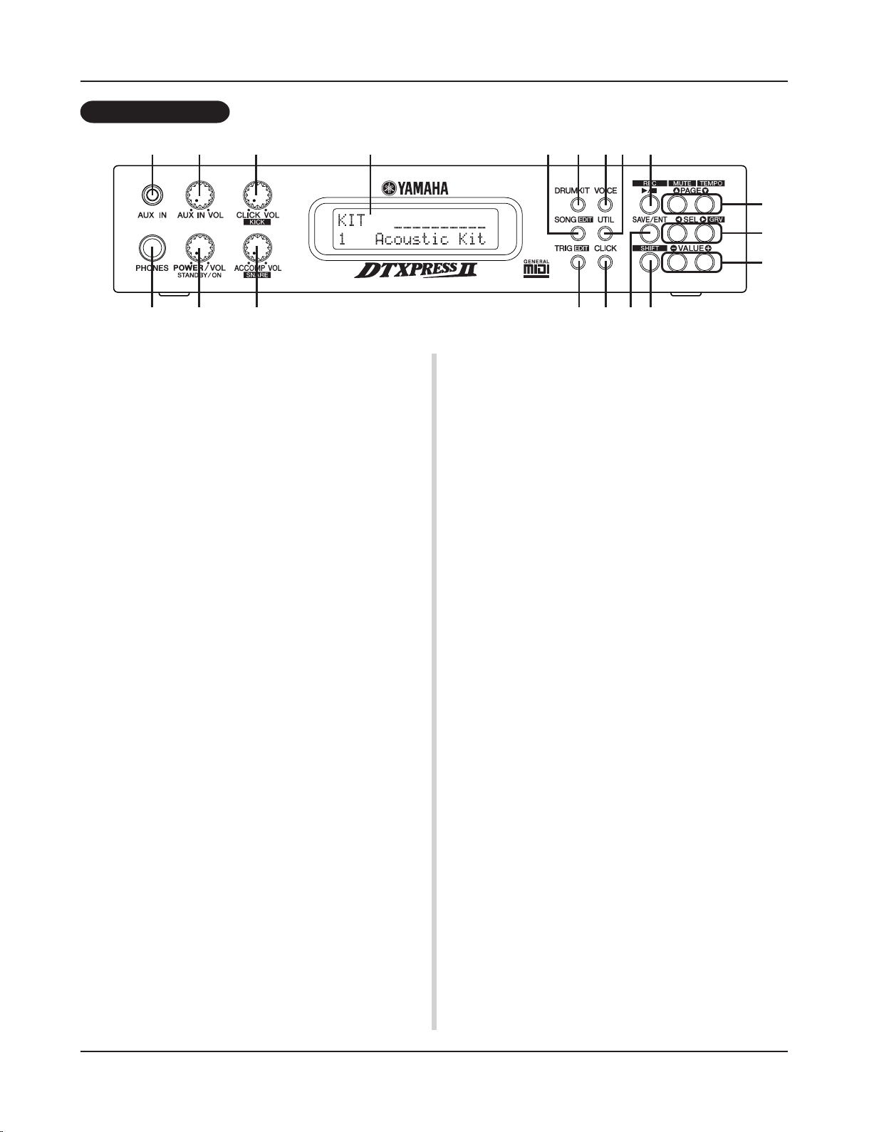
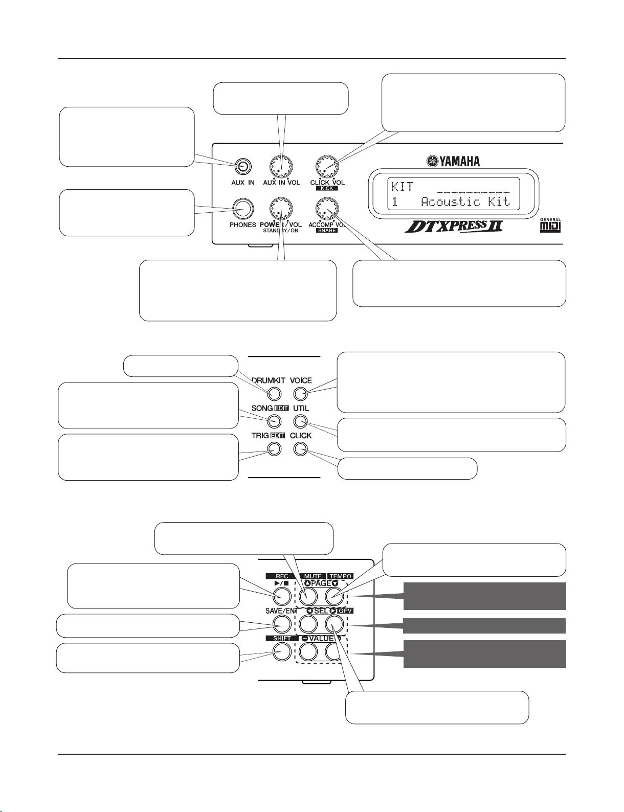
q AUX IN Jack
Connect the output of an external audio device, etc., to this jack
(stereo mini jack). (P. 13)
This is convenient for playing along with music from a CD or
cassette player.
w AUX IN Volume (AUX IN VOL)
This volume control adjusts the volume of a CD or cassette player
connected to the AUX IN jack q.
e Head Phone Jack (PHONES)
Connect a pair of headphones to this jack to monitor the
DTXPRESS II. (P. 13)
r Power Switch/Master Volume
(POWER/VOL)
Switches the power ON/OFF and controls the overall volume level
(output from the OUTPUT jacks and PHONES jack) of the
DTXPRESS II.
Rotate the knob clockwise to increase volume, counter-clockwise
to decrease volume. Push the button to switch the power ON/OFF.
t Click Volume (CLICK VOL)
This volume control adjusts the volume of the metronome’s click.
(P. 17)
Holding the [SHIFT] button and rotating the knob adjusts the volume of the bass drum.
y Accompaniment Volume (ACCOMP VOL)
This volume control adjusts the volume of the song’s accompaniment. (P. 18)
Holding the [SHIFT] button and rotating the knob adjusts the volume of the snare drum.
u LCD Display
The LCD Display shows information and data that is necessary to
operate the DTXPRESS II.
i Drum Kit Button (DRUMKIT)
Press the button to enter the DTXPRESS II’s Drum Kit Select
display.
o Song Button (SONG)
Press this button to enter the Song Select display.
Hold the [SHIFT] button and press the [SONG] button to enter the
Song Edit mode.
!0 Trigger Button (TRIG)
Press this button to enter the Trigger Setup Select display.
Hold the [SHIFT] button and press the [TRIG] button to enter the
Trigger Setup Edit mode.
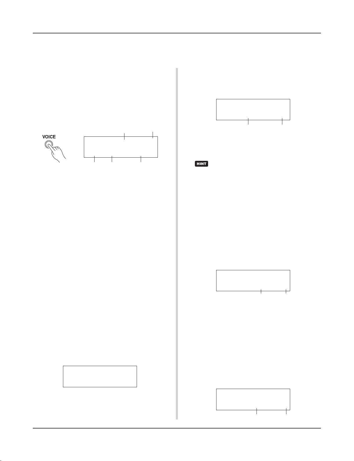
!1 Voice Button (VOICE)
Press this button to enter the Drum Kit Voice Edit Mode.
Press the button while in the Drum Kit Edit Mode allows you to
listen to the voice currently being set as if it where triggered from
the pad (audition function).
Hold the [SHIFT] button and press the [VOICE] button to mute audio output from the OUTPUT JACK @7 and PHONES JACK e.
!2 Utility Button (UTIL)
Press the button to enter the Utility Mode that contains basic settings for operation of the DTXPRESS II.
!3 Click Button (CLICK)
Press this button to start/stop the metronome (click sound). (P. 17)
!4 Start/Stop Button (>/■)
This button starts/stops playback or recording of the song.
Hold the [SHIFT] button and press [>/■] puts the DTXPRESS II
in recording standby mode.
!5 Save/Enter Button (SAVE/ENT)
Carries out (enter) the command or save operation.
!6 Shift Button (SHIFT)
Holding this button and pressing another specific button switches
the button to its secondary function.
!7 Page Button [PAGEs, PAGEt]
These buttons are used to navigate through the display pages. The
[PAGEs] button moves to the next page while the [PAGEt] button moves to the previous.
Controls and Functions
Front Panel
q w
e r
t u
y
i
!0
o !2
!3
!1 !4
!5 !6
!7
!8
!9
9
Hold the button to continuously move through the pages. Hold the
[SHIFT] button and press the [PAGEs] button to mute the drum
voice during playback (Rhythm Mute Function).
Hold the [SHIFT] button and press the [PAGEt] button to display the Song Tempo Setting (P. 18)
!8 Select Button [SEL<, SEL>]
Use these buttons to move the cursor.
Hold the [SHIFT] button and press the [SEL>] button to switch
to the “Groove Check Function”. (P. 17)
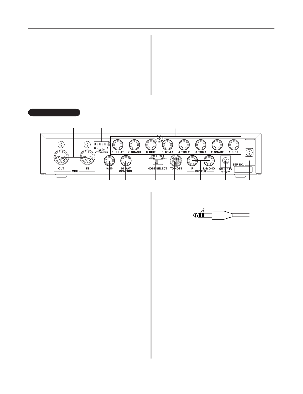
@0 MIDI IN/OUT Jack
These jacks are for the transmission and reception of MIDI data to
and from external MIDI devices.
Connecting external MIDI devices will expand the function of the
DTXPRESS II.
@1 Input Attenuation Switch
(INPUT ATTENUATION)
Sets the general Input Attenuation for each Trigger Input Jack (1
KICK-6 RIDE). Lowering the switch (L) lowers the attenuation.
Raising the switch (H) increases attenuation. This adjusts the input level to meet the specification of pads and trigger sensors connected to the DTXPRESS II. (P. 10)
@2 Trigger Input Jack (1 KICK-8HI HAT)
Connect pads and trigger sensors to these jacks. Connect pads according to the indication below each input. (P. 10)
Inputs 1-8 are compatible with switch type pads while inputs 2, 6,
and 7 are compatible with 3-zone type pads.
@3 Trigger Input Jack (9/10)
Used to connect a pad to the DTXPRESS II. The stereo jack’s L
corresponds to input 9, R corresponds to input 10. Using a stereo
phone plug to connect two pads makes two-trigger input possible.
If a monaural phone plug is used, only input 9 is available for use.
@4 Hi-Hat Controller Jack (HI HAT CONTROL)
This jack is used to connect a hi-hat controller (P. 10).
Rear Panel
* Use a cable with a stereo plug (shown below) when connecting a
Hi-hat controller.
!9 Value Button (VALUE–, VALUE+)
Changes the data value selected with the cursor.
Hold the button to continuously change the value.
Hold the [VALUE+] button and press the [VALUE–] button to
increase the value by 10 continuously.
Hold the [VALUE–] button and press the [VALUE+] button to
decrease the value by 10 continuously.
Controls and Functions
@0 @1
@3
@2
@4 @5 @6 @7 @8 @9
Double Insulator
@5 Host Select Switch
(HOST SELECT Mac/PC-1/PC-2/MIDI)
Set the switch according to the type of computer connected to the
TO HOST jack @6. If the MIDI jack is used set the switch to the
“MIDI” position. (P. 12, 26)
@6 TO HOST Jack
This jack is used to connect a computer to the DTXPRESS II with
a serial cable. Use a cable that is compatible with the type of computer you are using. (P. 26)
@7 Output Jacks (OUTPUT L/MONO, R)
These jacks are used to connect the DTXPRESS II to an external
amplifier, mixer, etc. For monaural playback use the L/MONO
jack. For stereo playback connect both L/R jacks.
@8 Power Supply Jack (DC IN 12V)
Connect an AC adaptor to this jack. To prevent the adaptor from
becoming unplugged, secure the cord to the cord hook @9.
@9 Cord Hook
Prevents the power cord from accidentally becoming unplugged.
(P. 13)
10
To prevent electric shock and damage to the devices, make sure the power is switched OFF on
the DTXPRESS II and all related devices before making any connections to the DTXPRESS II’s
input and output jacks.
Setting Up
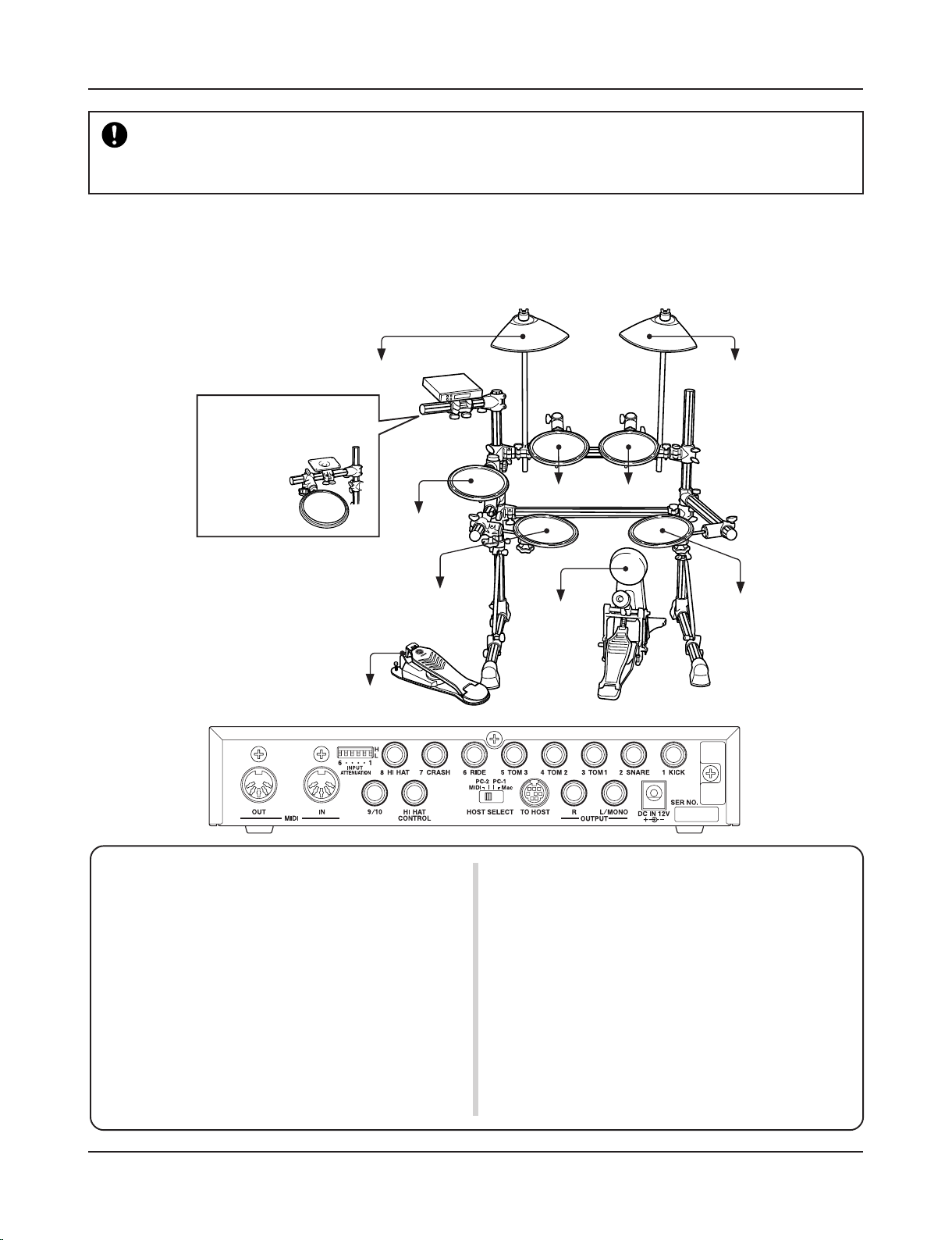
■ Connecting the pads
Referring to the illustration shown below, connect the output cable from each pad to each Trigger Input Jack located on the rear panel of the
DTXPRESS II.
The Trigger Input Jacks are all labeled (1 KICK, etc.) so make sure you connect each pad to its corresponding Trigger Input Jack.
• Trigger Input Jacks are all stereo input type jacks.
Pads equipped with trigger switches like the TP65S, PCY65S, etc.
can be connected to these jacks.
• It is possible to connect 3-zone type pads like the TP65S to Trigger
Input Jacks 2 SNARE, 6 RIDE, and 7 CRASH.
• When a pad corresponding to the labeled input jack (1 KICK, etc.)
is connected, the DTXPRESS II will automatically assign settings
suitable for the pads. However, when pads and drum triggers that
possess different characteristics are connected, it will be necessary
to assign suitable settings for parameters such as sensitivity, etc.
• Sensitivity is set in the Trigger Setup Edit mode’s [1-1. Pad Type]
(Reference Guide : P. 12).
• The input sensitivity switches (INPUT ATTENUATION) are sensitivity switches that correspond to Trigger Input Jacks 1 KICK-6 RIDE.
The switch’s L position corresponds to a low sensitivity for pads
like TP, KP, PCY, BP, etc. The H position corresponds to a high
sensitivity proper for use with the DT20 Drum Trigger, etc.
• It is possible to connect the TP65, TP65S, PCY65S, etc. pads to the
1 KICK jack. You can also use the Hi-Hat Controller HH series as a
kick pedal (Use [1-1. Pad Type] (Reference Guide : P. 12) to assign
settings.).
• In addition to the 1 KICK jack, the 9/10 jack can be used to connect
a second bass drum pedal to create a double-bass drum set.
• The 9/10 jacks correspond to a 2-trigger input that uses a stereo jack
for L (9) and R (10). We recommend the use of these jacks when
connecting the Yamaha Bar Pad (BP-80).
You can use an conversion cable plug (stereo plug m monaural plug
x2) to input two separate trigger signals.
to 6 RIDE
to 7 CRASH
to 3 TOM1 to 4 TOM2
to 2 SNARE
to 5 TOM3
to 8 HI HAT
to 1 KICK
to HI HAT CONTROL
Caution)
A cable equipped with a
stereo plug is required
when connecting the
Hi-Hat Controller.
The hi-hat drum pad clamp
can also be attached to
this arm.
11
■ Removing the Drum Triggers
When changing the batterhead, carefully remove the drum trigger sensors with a knife, etc. before loosening the head.
* Be careful not to pull the cord when removing the trigger.
Setting Up
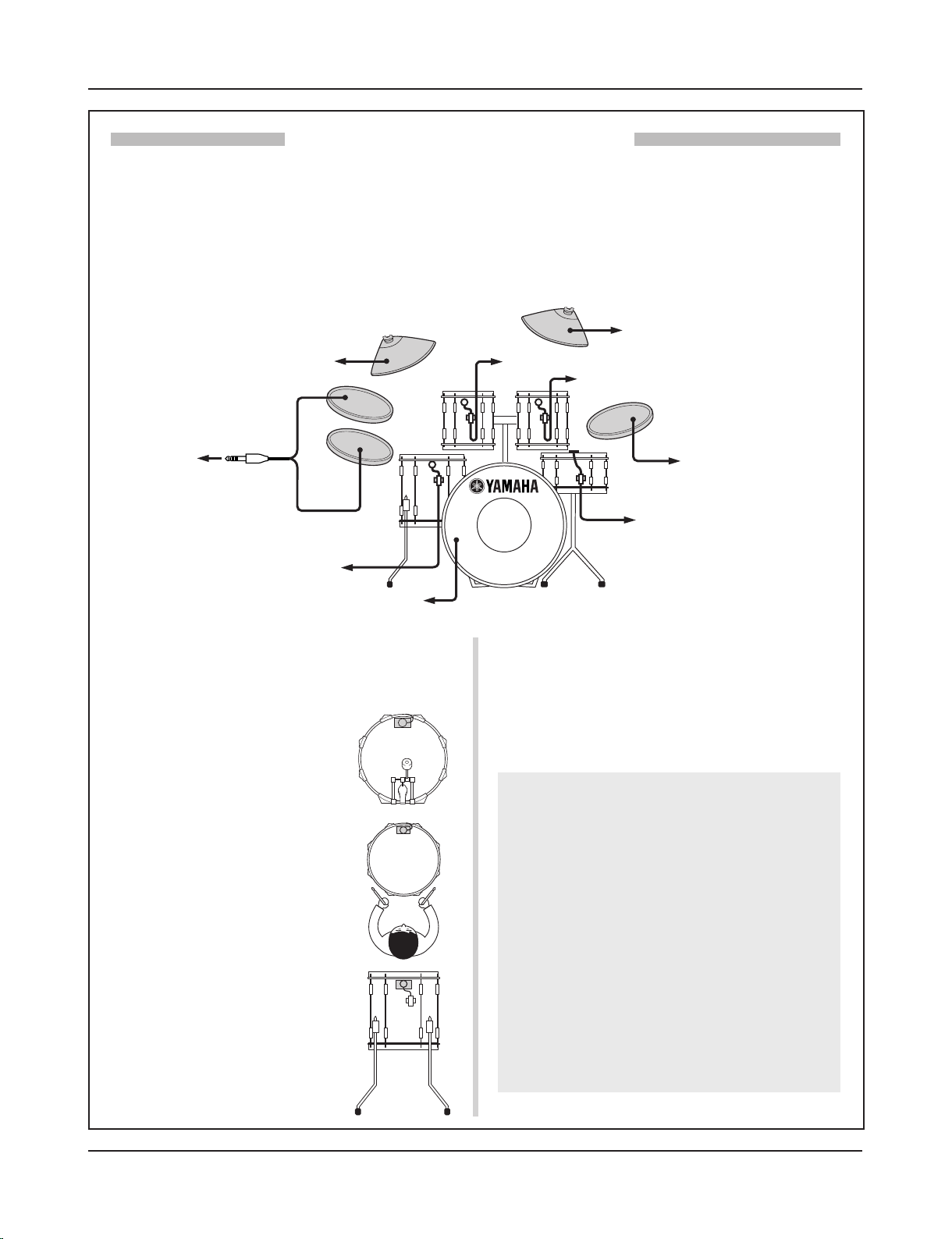
■ Attach the Drum Trigger
Use the following procedure to attach the drum trigger sensors to your
acoustic drums.
• Attach to the Bass Drum
Mount the drum trigger sensor on the
batterhead of the bass drum close to the
edge of the rim.
* Make sure the sensor does not come in
contact with the rim.
• Attach to the Snare Drum
Mount the drum trigger sensor on the
batterhead of the snare drum close to the
edge of the rim across player.
* Make sure the sensor does not come in
contact with the rim.
• Attach to the Toms
Mount the drum trigger sensor on the shell
close to the edge of the rim.
* Make sure the sensor does not come in
contact with the rim.
* Place the trigger in a position where other
instruments (drum or percussion) will not
influence it.
With the optional Yamaha DT20, etc. Drum Triggers attached to a set of acoustic drums, it is possible to connect
acoustic drums to the DTXPRESS II.
■ A setup example using both acoustic drums and drum pads.
Referring to the illustration shown below, connect the output cable from each pad and drum trigger to each Trigger Input Jack located on the rear
panel of the DTXPRESS II.
* When using the drum triggers, appoint suitable settings in the Trigger Setup Edit mode’s [1-1. Pad Type]. (Reference Guide : P. 12)
Setting up with Acoustic Drums
Taking Care of the Drum Triggers
• Make sure the surface of the batterhead or shell where
the trigger is to be mounted is free from dirt and grime.
Clean the surface with alcohol, etc. before attaching.
• To prevent broken trigger cords caused by the vibration
of the drum rim, secure the sensors and cords in place
with tape.
• Irregular vibration and sustained resonance on the
batterhead or shell may cause double-triggering. This
can be prevented by applying a mute to the batterhead
and controlling excessive vibration. We recommend the
use of the Yamaha Ring Mute.
• Once you have removed drum triggers and want to mount
them again, be sure completely remove the old tape and
apply new tape. Using used tape may cause problems
such as poor sensitivity, double-triggering, etc.
to 7 CRASH
to 3 TOM1
to 6 RIDE
to 4 TOM2
to 2 SNARE
to 5 TOM3
to 8 HI HAT
to 1 KICK
to 9/10
9
10
12
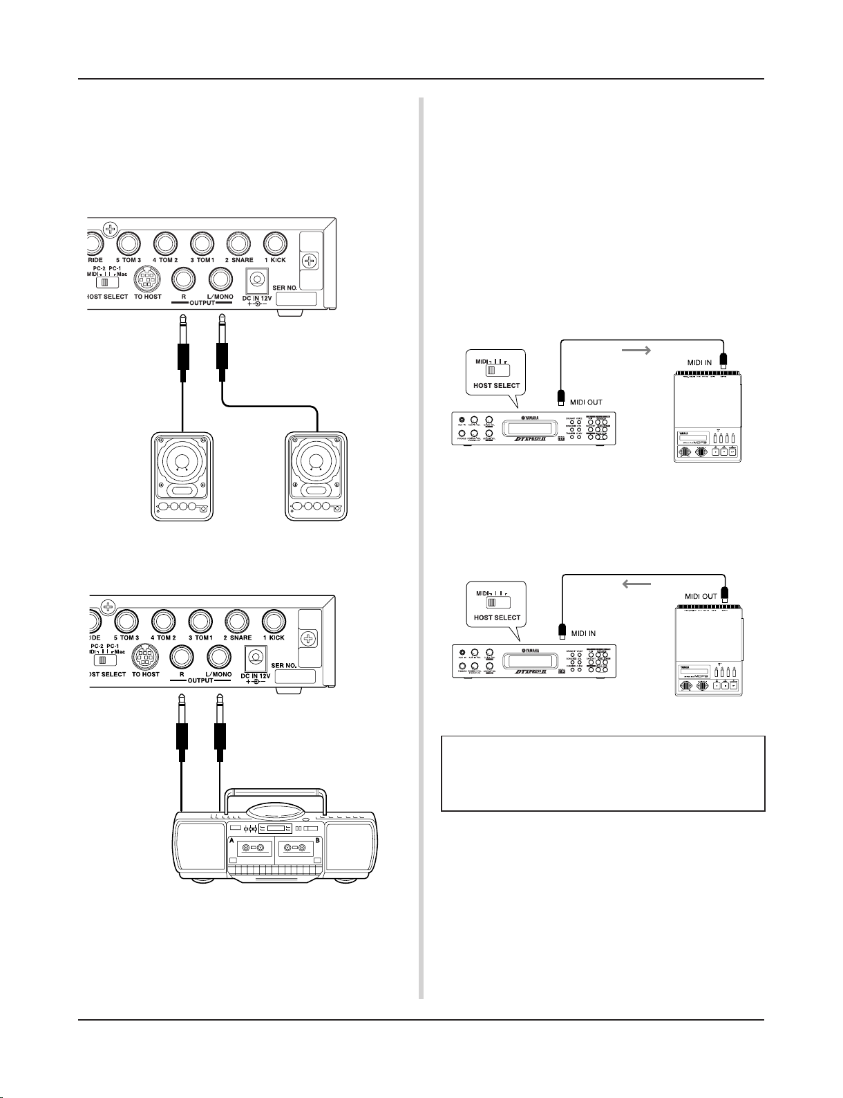
■ Connecting a Mixer or Audio Equipment
Connecting the OUTPUT L/MONO and R jacks on the rear of the
DTXPRESS II to a mixer or audio equipment allows for audio
reproduction through external speakers or the recording of your
performance.
• Using speakers with built-in amplifiers.
* The OUTPUT jack is a standard monaural type phone jack. Please
use a cable equipped with a plug that matches device.
* When connecting to a monaural input device, please use the OUT-
PUT L/MONO jack on the DTXPRESS II.
Setting Up
• Recording your performance with the DTXPRESS II to
a cassette tape deck.
■ Connecting a MIDI Device
Data in the DTXPRESS II can be stored (Bulk Dump) to a Yamaha
MIDI Data Filer MDF3, etc. or other MIDI device.
Also, an external sequencer can be used to drive the DTXPRESS
II’s Tone Generator.
Furthermore, the use of MIDI functions allows for a wide range of
possibilities with the DTXPRESS II.
Refer to the [Using MIDI] section (P. 25) on how to use MIDI
functions.
■ Connecting a Computer
The DTXPRESS II is equipped with a built-in MIDI interface that
allows the DTXPRESS II to be connected directly to a computer’s
serial board via the DTXPRESS II’s TO HOST jack.
Sequencer software installed in the computer can be used to drive
the keyboard voices of the DTXPRESS II and sequence data created in the DTXPRESS II can be edited in the computer.
Refer to the [Connecting a Computer] section (P. 26) for more
information.
• Transmit MIDI Data
Use a MIDI cable to connect the MIDI OUT jack on the DTXPRESS
II with the MIDI IN jack on the external MIDI device.
Set the HOST SELECT switch to the “MIDI” position.
MIDI Device
• Receive MIDI Data
Use a MIDI cable to connect the MIDI IN jack on the DTXPRESS
II with the MIDI OUT jack on the external MIDI device.
Set the HOST SELECT switch to the “MIDI” position.
Always use a standard MIDI cable when connecting devices. Also, use a MIDI cable that is more than 15m in
length. Using a longer cable may result in irregular operation and other problems.
Set to “MIDI”
MIDI Data
DTXPRESS II
MIDI Device
Set to “MIDI”
MIDI Data
DTXPRESS II
13
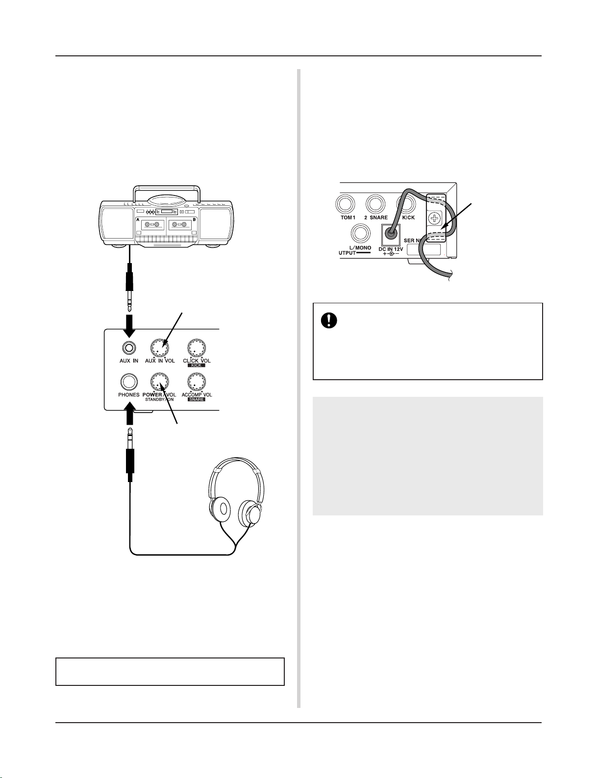
■ Connecting a CD Player, etc. (AUX IN jack)
The audio output from a CD player or cassette deck connected to
the AUX IN jack (stereo mini) on the front panel can be mixed
with the sound of the DTXPRESS II and transmitted via the output jacks on the rear panel.
This function is convenient when you want to play along with a
favorite song or enjoy performing with your friends.
The volume of the external signal is adjusted with the AUX IN
VOL knob.
■ Connecting the Power Supply
A special power source adaptor supplies power to the
DTXPRESS II.
Make sure the power is switched OFF and connect the supplied
power adaptor to the DC IN jack on the rear panel.
To prevent the cord from becoming unplugged, wrap the cord
around the cord hook and secure.
Setting Up
Adjusts the volume of the headphones.
Adjusts the volume of the AUX IN input jack.
■ Connecting a Pair of Headphones
(PHONES jack)
When you want to listen to the DTXPRESS II with a pair of headphones, connect the headphones to the PHONES jack (stereo standard) on the front panel.
The headphone volume is adjusted with the POWER/VOL knob.
When using the headphones, do not damage your hearing. Adjust the volume to a comfortable level.
Please use the supplied power adaptor. The use of
any other power source may cause irregular operation or damage to the device.
Also, when the DTXPRESS II is not to be used for
a long period of time, please unplug the power adaptor.
cord hook
Before switching the power ON.
• To protect the speakers, headphones and the
DTXPRESS II from damage, fully rotate the
POWER/VOL knob to the left (minimum volume)
before switching the power ON.
• Make sure the power is switched OFF on all external devices connected to the DTXPRESS II.
After the DTXPRESS II’s power is switched ON,
switch the other device’s power ON.
14
Select the drum kit.
Change the instrument voice for each pad in the drum kit
or add reverb. m Enters the Drum Kit Voice Edit mode.
Hold the [SHIFT] button and press the [VOICE] button to
stop audio output from the OUTPUT and PHONES jacks.
Hold the [SHIFT] button and press this
button to mute the song’s drum part.
Start/stop playback of the song!
Hold the [SHIFT] button and press this
button to start recording.
Save settings to the DTXPRESS II’s memory.
Set a secondary function for the buttons and
knobs.
Hold the [SHIFT] button and press this button to display the Tempo setting display!
Navigate through the setting display’s
pages.
Moves the cursor (flashing character).
Changes the value of the parameter
selected with the cursor.
Hold the [SHIFT] button and press this button to display the Groove Check display!
Select the song for playback or recording.
Hold the [SHIFT] button and press the
[SONG] button to enter the Song Edit mode.
Select the Trigger Setup you want to use.
Hold the [SHIFT] button and press the [TRIG]
button to enter the Trigger Setup Edit mode.
Set the basic settings and settings for MIDI and the sequencer of the DTXPRESS II. m Enters the Utility mode.
Starts/stops the metronome!
The DTXPRESS II Quick Guide (Basic Functions List)
Control the volume of a CD
or MD player with this knob.
Controls the volume of the metronome’s
click voice!
Hold the [SHIFT] button and rotate this knob
to change the volume of the bass drum!
Controls the volume of the song accompaniment!
Hold the [SHIFT] button and rotate this knob to
change the volume of the snare drum!
Press the knob to switch the power ON!
Rotate the knob to adjust the overall volume
(transmitted to the OUTPUT jack).
Also controls the headphone volume.
Play the DTXPRESS II along
with your favorite CD or MD!
(Connect the line out from a
CD or MD player here.)
Connect a pair of headphones here to monitor the
DTXPRESS II!
15
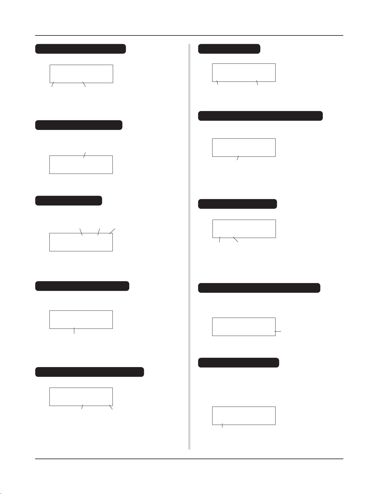
The DTXPRESS II Quick Guide (Basic Functions List)
SONG ƒ=110 4/4 ƒ
1
HighRise -ß
SONG ƒ=110 4/4 ƒ
1
HighRise -ß
TRIG IN= 1 ( 0%)
Gain=64
MVel= 32
KIT ´´´´´´´´´´
1
Acoustic Kit
KIT IN=kick V=Vol=
116 Pan= C
KIT IN=kick V==K/017
BDaftty1
KIT IN=kick
Reverb
send= 15
Store Drumkit
=49
User Kit
Listen to the Selected Song
1. Press the [SONG] button to open this display,
Song Number Song Name
2. Make sure the song number in the display is flashing.
3. Use the [VALUE–]/[VALUE+] buttons to select the song.
4. Press the [>/■] button to start playback!
Change the Song’s Tempo
1. Hold the [SHIFT] button and press the [PAGEt] button to
open this display,
2. Make sure the tempo value in the display is flashing.
3. Use the [VALUE–]/[VALUE+] buttons to set the tempo.
Set the Metronome
1. Hold the [SHIFT] button and press the [PAGEt] button to
open this display,
Tempo
Tempo Beat Note
2. Use the [SEL<]/[SEL>] buttons to flash the parameter you
want to set.
3. Use the [VALUE–]/[VALUE+] buttons to set the value.
Change the Pad’s Sensitivity
1. Hold the [SHIFT] button and press the [TRIG] button, then
press the [PAGEt] buttons to open this display,
Input Gain (Sensitivity)
2. Hit the pad that you want to edit (that pad will be selected).
3. Use the [SEL<]/[SEL>] and [VALUE–]/[VALUE+] buttons
to edit.
Change the Output Sound Quality
1. Press the [UTIL] button to open this display,
Bass Treble
UT TG MASTER
EQ
Lo=+ 6 Hi=+ 0
2. Use the [SEL<]/[SEL>] buttons to select either “Lo” (bass)
or “Hi” (treble),
3. Use the [SEL<]/[SEL>] and [VALUE–]/[VALUE+] buttons
to edit.
Drum Kit Number Drum Kit Name
2. Make sure the drum kit number in the display is flashing.
3. Use the [VALUE–]/[VALUE+] buttons to select a drum kit.
Change the Voice Volume For Each Pad
1. Press the [VOICE] button, then press the [PAGEt] button to
open this display,
2. Hit the pad whose volume you want to change (that pad will
be selected),
3. Use the [SEL<]/[SEL>] and [VALUE–]/[VALUE+] buttons
to edit.
Change the Pad’s Voice
1. Press the [VOICE] button to open this display,
2. Hit the pad whose voice you want to change (that pad will be
selected),
3. Use the [SEL<]/[SEL>] and [VALUE–]/[VALUE+] buttons
to select the voice category and voice number.
Change the Reverb for the Drum Voice
1. After selecting the drum kit you want to add reverb to, press
the [VOICE] button, use the [PAGEs]/[PAGEt] buttons to
open this display.
2. Use the [SEL<]/[SEL>] and [VALUE–]/[VALUE+] buttons
to edit the reverb send level.
Save the Edited Settings
1. Press either the [VOICE] or, hold the [SHIFT] button and press
the [TRIG] button to enter their respective edit mode displays
to edit settings.
2. Press the [SAVE/ENT] button,
3. Use the [VALUE–]/[VALUE+] buttons to set the save address.
Select a Drum Kit
1. Press the [DRUMKIT] button to open this display,
Volume Level
Voice Category
Voice Number
Reverb Send Level
Save Address
SONG ƒ=110 4/4 ƒ
1
HighRise -ß
4. Press the [SAVE/ENT] button, after the confirmation display
appears, press the [SAVE/ENT] button again.
16
KIT ´´´´´´´´´´
1
Acoustic Kit
KIT ´´´´´´´´´´
2
New Beat
Now that you have the DTXPRESS II properly connected, let’s make some music!
4. Change the instrument volume for each pad.
• Hold the [SHIFT] button and rotate the CLICK VOL knob to
adjust the volume of the Bass Drum.
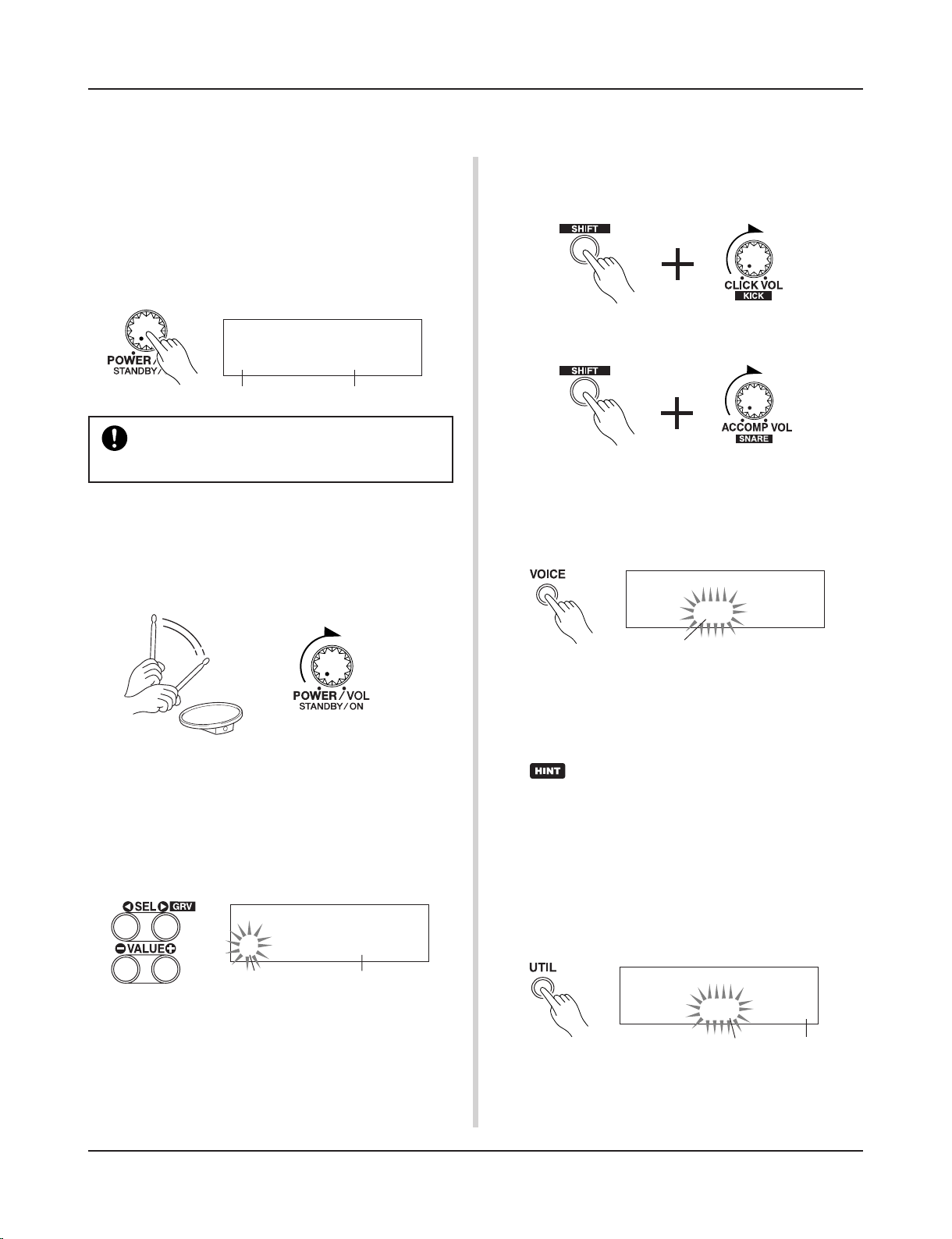
Play the DTXPRESS
II
!
1. Switch the power ON
After confirming that each of the devices, pads, external devices, etc. are all properly connected, push the POWER/VOL
knob on the front panel to switch the power ON.
The DTXPRESS II is ready to operate when the display, shown
below, for selecting the drum kit appears.
* The previously selected drum kit will be displayed.
To avoid damage to your speakers, first switch the
DTXPRESS II’s power ON then switch on Audio
Devices and the Mixer or Amplifier.
2. Hit a pad
While hitting a pad, rotate the POWER/VOL knob little by
little to the right until a comfortable volume level is reached.
The volume level is increased as the knob is rotated to the
right and decreased as it is rotated to the left.
3. Change the Drum Kit
Try out the voices for each of the kits.
Drum kit numbers 1-48 consist of 48 types of preset drum
kits that have been specially programmed by Yamaha. m [Preset Drum Kit List] (Reference Guide : P. 42)
Use the [VALUE–]/[VALUE+] buttons to select the drum kit.
Try out the different drum kits and select one drum kit you
like.
* Some drum kits have Pad Songs and Drum Loop Voices
that will start when the corresponding pad is hit.
• Hold the [SHIFT] button and rotate the ACCOMP. VOL knob
to adjust the volume of the Snare Drum.
* The Bass Drum and Snare Drum volume settings, described
above, will reset when the power is switched off.
• Press the [VOICE] button, then press the [PAGEt] button
to enter the volume setting display for the currently selected
pad (Input Source).
Hit the pad you want to adjust the volume of and use the
[VALUE–]/[VALUE+] buttons to adjust the volume.
* The same display can be used to adjust the pan (the posi-
tion of the voice within the stereo field) for each pad. (Reference Guide : P. 17)
According to the setting in the Utility mode’s [1-3.
Volume Mode] (Reference Guide : P. 28), the volume of the cymbal, drums and other instruments can
be adjusted using the knobs shown above.
5. Change the sound quality heard through
the monitor.
Press the [UTIL] button, the sound quality setting display for
the audio signal that is transmitted to the OUTPUT jacks and
PHONES jack will be displayed.
Volume
UT TG MASTER
EQ
Lo=+ 6 Hi=+ 0
Press the [SEL<]/[SEL>] buttons to move the flashing cursor to the Lo or Hi position, then use the [VALUE–]/[VALUE+]
buttons to adjust the sound quality.
Treble
Bass
Drum Kit NameDrum Kit Number
Drum Kit NameDrum Kit Number
KIT IN=snare V=Vol=
116 Pan= C
17
Play the DTXPRESS II along with the metronome.
Try out the Groove Check Function to check your rhythmic accuracy.
2. Use the Groove Check Function
As you play the pads, the DTXPRESS II’s Groove Check function will check your rhythmic accuracy and display the results.
Your timing is compared to the click of the metronome and
the accuracy is displayed.
2-1. Set the Metronome
Before you use the Groove Check Function, you will have to
select the tempo, beat and finer quantization that matches the
type of rhythm you want to practice.
2-2. Display the Groove Check Function
Hold the [SHIFT] button and press the [SEL>] button to display the Groove Check Function shown below.
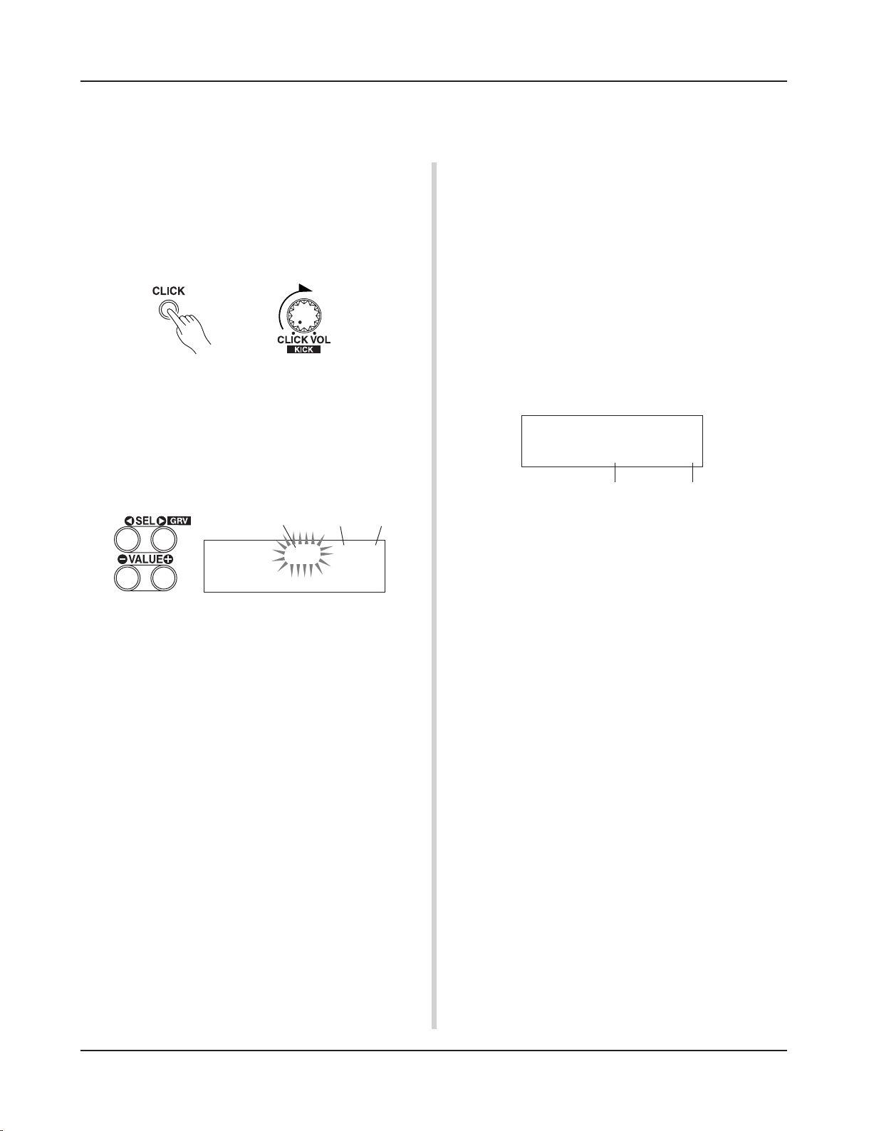
Play Along with the Metronome
1. Turn On the Metronome
Press the [CLICK] button to start the metronome.
The lamp in the [CLICK] button will light every beat of each
measure.
Press the [CLICK] button again to stop the metronome.
The click voice volume is adjusted with the CLICK VOL knob.
1-1. Set Metronome Tempo
Hold the [SHIFT] button and press the [PAGEt] button, the
tempo setting display will appear.
Use the [SEL<]/[SEL>] buttons to move the flashing cursor
to the tempo value, then use the [VALUE–]/[VALUE+] buttons to set the desired tempo.
The Tempo setting range is q=30-300.
Tempo Value
1-2. Set the Metronome Beat
In the setting display shown above, press the [SEL>] button
to move the flashing cursor to the beat value, then use the
[VALUE–]/[VALUE+] buttons to set the desired beat.
The Beat setting range is 1/4-8/4, 1/8-16/8, 1/16-16/16.
1-3. Set the Metronome Note Value
In the setting display shown above press the [SEL>] button to
move the flashing cursor to the note value, then use the
[VALUE–]/[VALUE+] buttons to set the click tempo (finer
quantization).
1-4. Set the Click Voice and Other Settings
The metronome produces three different click voices.
“hi” will sound at the top of the measure, “mid” will sound
on every quarter note and “lo” will sound on the beats of
finer quantization.
Each of the click voices can be set to any voice (drum instrument voices) and pitch you like.
In the next section [Play with the Song] we will explain how
to change the voices in detail.
Refer to the Utility mode’s [4. Sequencer Group] (Reference
Guide : P. 33) section for more information.
Note Value
2-3. Hit a Pad in Tempo with the Metronome
Press the [CLICK] button to start the metronome, then hit the
snare drum pad.
• The number that is displayed next to “Groov=” on the left
side of the display indicates the accuracy of each stroke on
the pad.
A “–” (minus) value is displayed when your timing is later
than that of the click voice (just timing) and a “+” (plus)
value is displayed when your timing is earlier than that of
the click voice.
• The number that is displayed next to “Avg=” on the right
side of the display indicates the overall accuracy or average of the values that are displayed next to “Groov=”. The
Groove Function can be used to check your accuracy on
the entire drum set or on an entire song.
The Groove Check Function can be used not only on the snare
drum, but on any of the DTXPRESS II’s pads. Also, you can
change the metronome’s pattern to a sixteenth or triplet note
feel. Try practicing with some of the other settings.
* Hold the [SHIFT] button and press the [SEL>] button twice
to reset the data.
GRV -----¨----Groov=+12Avg=+
6
Average accuracyAccuracy of each stroke
SONG ƒ=110 4/4 ƒ
1
HighRise -ß
Beat
18
SONG ƒ= 94 4/4 ƒ
2
Horizon -ß
The metronome (click voice) can be set to start/stop
when the song starts/stops. (m [4-8. Click Mode] Reference Guide : P. 35)
The DTXPRESS II has a total of 95 preset songs that are good for rhythm practice.
Try and play along with a song.
While setting the Rhythm Mute, a “˚” will be displayed at the
end of the song name.
Play Along with a Song
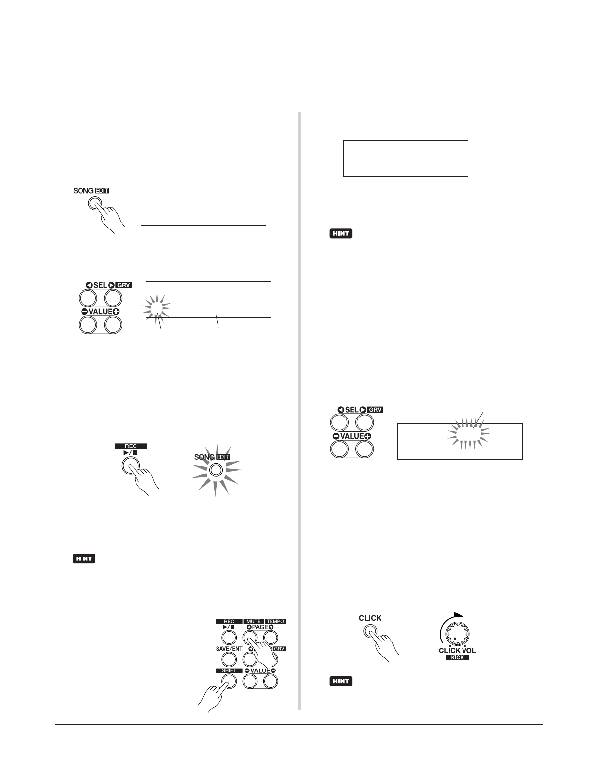
1. Select a Song
Select one of the DTXPRESS II’s songs and listen to it. Song
numbers 1-95 are preset songs that have been created by
Yamaha.
m [Preset Song List] (Reference Guide : P. 49)
Press the [SONG] button to display the Song select display.
Use the [SEL<]/[SEL>] buttons to move the flashing cursor
to the song number, then use the [VALUE–]/[VALUE+] buttons to select the song.
SONG ƒ=110 4/4 ƒ
1
HighRise -ß
* When a song is switched, the drum kit also changes to a kit
that is set for that song.
2. Listen to the Song
When the [>/■] button is pressed, the song will start playback from the beginning.
The [SONG] lamp in the button will blink on the first beat of
each measure.
Song Number
Song Name
The song will stop when it reaches the end.
You can stop the song during playback by pressing the [>/■]
button.
* Some songs repeat.
To cancel the Rhythm Mute, hold the [SHIFT] button and press
the [PAGEs] button again.
The mute function can be used during song playback.
4. Adjust the Song Volume
The song volume is adjusted with the ACCOMP VOL knob.
Use both the ACCOMP VOL knob and the POWER/VOL knob
(overall volume of song and pads) to adjust the balance between the song and your drum part.
5. Change the Song’s Tempo
Hold the [SHIFT] button and press the [PAGEt] button to
display the Tempo Setting display.
Make sure the Tempo value in the display is flashing, then use
the [VALUE–]/[VALUE+] buttons to set the desired tempo
(q=30-300).
SONG ƒ=110 4/4 ƒ
2
Horizon˚ -ß
Indicates the Rhythm Mute
SONG ƒ= 94 4/4 ƒ
2
Horizon -ß
Tempo Value
6. Play Along with the Click Voice
With the drum part muted, it may be a little difficult to keep
time. In this case, use the metronome along with the song.
Using the click voice as a reference will make it easier to play
along with the song.
Press the [CLICK] button to start the metronome. It will be in
tempo with the song. Press the [CLICK] button again to stop
the metronome.
The Click Voice’s volume can be adjusted using the CLICK
VOL knob.
Before song playback, you can have the metronome
give a two-measure count. (m Utility Mode [4-5.
Count Switch] Reference Guide : P. 34)
3. Mute a Drum Part
Try playing along with the song.
Hold the [SHIFT] button and press the
[PAGEs] button, then press the [>/
■] button to playback the song. A
drum part in the song will be muted
(does not produce the part) (Rhythm
Mute Function).
You will play the drum part.
19
KIT ´´´´´´´´´´
1
Acoustic Kit
7. Change the Click Voice
When the click voice resembles voices that are found in the
song it might be hard to hear. In this case it is a good idea to
change the click voice.
• We will use the factory set 4-beat click voice (a high
and low bell voice) as an example here.
Change voice that is heard on the first beat.
Slowly press the [UTIL] button four times and the following
display will appear.
8. Change the Drum Kit
When you want to use a different drum kit with a particular
song, press the [DRUMKIT] button to enter the Drum Kit select display, then select the drum kit you want to use.
7-1. First, use the [SEL<]/[SEL>] buttons to move the flash-
ing cursor to the Click Voice Type position, then use the
[VALUE–]/[VALUE+] buttons to assign the “hi” click
voice (the click voice heard on the first beat).
7-2. Next, use the [SEL<]/[SEL>] buttons to move the flash-
ing cursor to the Voice Category position, then use the
[VALUE–]/[VALUE+] buttons to assign the Drum Voice
Category that will be used for the Click Voice.
Each of the following characters indicates a drum voice
category.
K: Acoustic Kick
k: Electric Kick
S: Acoustic Snare
s: Electric Snare
T: Acoustic Tom
t: Electric Tom
C: Cymbal
H: Hi-hat
P: Percussion
E: Effect 1
e: Effect 2
L: Drum Loop
m: misc. voices
Here, select the misc. voices “m”.
7-3. After selecting the category, press the [SEL>] button to
move the flashing cursor to the Voice Number, then use
the [VALUE–]/[VALUE+] buttons to assign the drum
voice that will be used for the click voice.
Here, select “010
Marimba”.
Press the [CLICK] button to start the metronome and the
marimba voice will be delivered instead of the previously
assigned voice.
The same procedure can be used to change the other click
voices (“mid”, “lo”) to a voice you prefer.
Press the [SONG] button to return to the original display
(Song select display).
UT SEQ Click= hi
=P/053
MtBel
Click Voice Type
Voice Category Voice Number Voice Name
Play Along with a Song
Drum Kit Name
9. Change the Song but Not the Drum Kit
Normally, when the song is switched the drum kit will be automatically switched to the kit that is set in the song. However,
if the Rhythm Mute Function ([SHIFT]+[PAGEs]) is used,
the drum kit will not change when the song is switched.
* Also, in the Utility mode’s [3-2. Channel 10 Program Change/
Receive Channel Event] (Reference Guide : P. 31) set the
Channel 10 Program Change to not receive program
changes and then only the song will change.
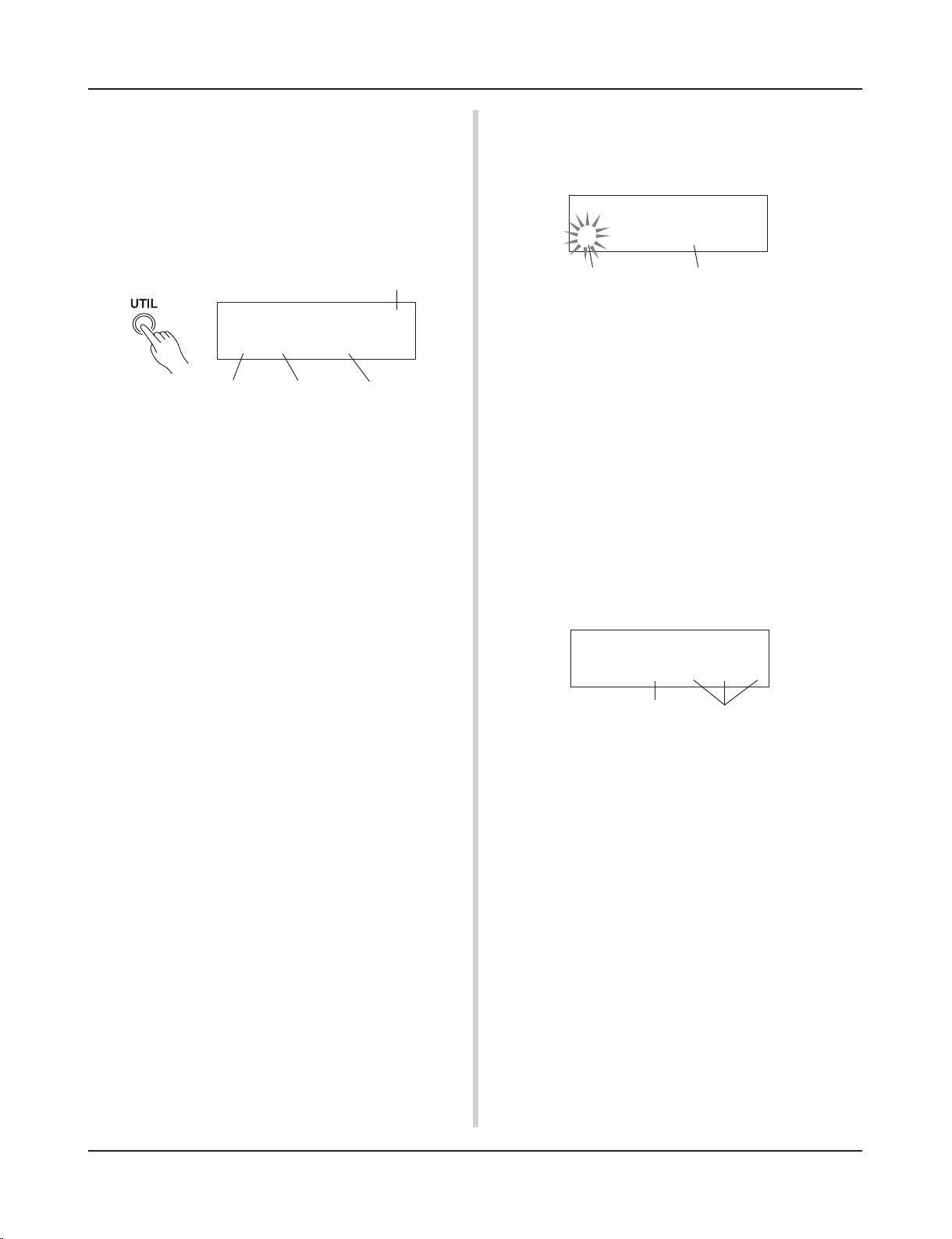
10. Mute Individual Drums
You can mute individual drums like the [Bass Drum], [Snare
Drum], [Cymbal], [Other Drum Instruments].
This function is convenient when you want to practice individual drum parts.
Press the [UTIL] button, then press the [PAGEt] button to
enter this display.
Drum Kit Number
Produces sound
Use the [SEL<]/[SEL>] buttons to select the drum instrument (K: Bass Drum, S: Snare Drum, C: Cymbal, M: others)
you want to mute, then press the [VALUE+] button to change
the speaker icon (®) to the mute icon (m).
To cancel the Mute Function, press the [VALUE–] button to
return to the speaker icon (®).
UT TG MASTER
MuteK=mS=®C=®M=®
Mute (Does not produce sound)
20
Next, let’s try recording your performance to the DTXPRESS II’s sequencer.
With song data you record you can switch drum kits, change the tempo and playback
in the same way as preset songs.
* When there is data in the other track, the number of mea-
sures in that track will determine the length of the song.
2-2. Select the Record Mode
Select the method for recording from the following record
modes.
Overwrite (Ovr): The record operation will be in a repeat
mode. When the song reaches the end of the last measure, it will automatically start again from the beginning
and new data will be added to the track’s previous data.
Replace (Rpl): When the song reaches the end of the as-
signed measure or the [>/■] button is pressed, record-
ing will stop (will not repeat).
2-3. Set the Track For Recording
Select either track 1 or 2 for recording.
2-4. Set the Metronome’s Tempo and Beat
Set the tempo and beat that will be used by the Metronome
when recording.
2-5. Set the Quantize Function
The Quantize function is used to align the timing of your performance with that of the nearest specified beat. The accuracy
of quantization is assigned with a note value. The quantize
function can be used when recording.
* If this function is set to “no”, the quantize function will not
operate.
* You can use the Quantize function after recording is com-
plete. (Reference Guide : P. 25)
Record Your Performance
■ Recording System
• Recording can be done in any of the user songs (No. 96-127)
that supplied for recording. You cannot record to preset songs
(No. 1-95).
• User songs contain 2 tracks that can be recorded to. Recording can be done one track at a time.
• The song records (memory) data that precisely relates to when
and how each pad was hit, and stores that information. This
is called sequence data. MIDI data from the MIDI IN/TO
HOST jacks can be recorded simultaneously.
• Sequence data can be freely used to change the tempo, select
the voice or drum kit during playback.
m Reference Guide : P. 24 [2. Program Change, Bank Select]
• Before recording, set the number of measures for the song
you want to record. Recording is done in real-time. When
the end of the assigned measure is reached, the record function can be set to act in one of two ways. (1) The song will
automatically stop (Replace) and recording will be complete.
(2) The song will repeat from its beginning and further data
can be added to the previously recorded data (Overwrite).
OK, Let’s Start Recording
1. Select the Song You Want To Record
Press the [SONG] button to display the Song select display,
select a User Song number (No. 96-127).
* User songs that already contain data in both tracks cannot
be recorded to.
* If a song is not selected when you start to record, the lowest
numbered empty user song will automatically be selected to
record. In the same manner, an empty user song will be selected if a preset song has been selected for recording.
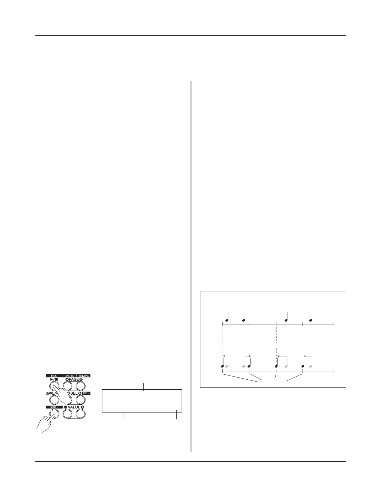
2. Set the Recording Conditions
Hold the [SHIFT] button and press the [>/■] button, the fol-
lowing Recording Conditions setting display will appear.
Use the [SEL<]/[SEL>] buttons to select the parameter you
want to set, then use the [VALUE–]/[VALUE+] buttons to set
each of the following recording conditions.
REC M= 32=Rp1†=1
ƒ=120
B= 4/4Q= ©
Quantize
Beat
Tempo
Track
Record Mode
Number of Measures for
Recording
2-1. Set the Number of Measures to be Recorded.
Determine the number of measures you want to record and set.
● How Quantize Works (an example)
• Recorded notes were not played in time.
Just Timing
3. Start Recording
Press the [>/■] button, after a two-measure count recording
will start. Record while listening to the metronome’s click
voice.
* When the track assigned for recording contains data and
the [>/■] button is pressed, the error message “Data
not
Empty” will appear and the recording operation will not be
carried out.
• The Quantize Function aligns the timing.
21
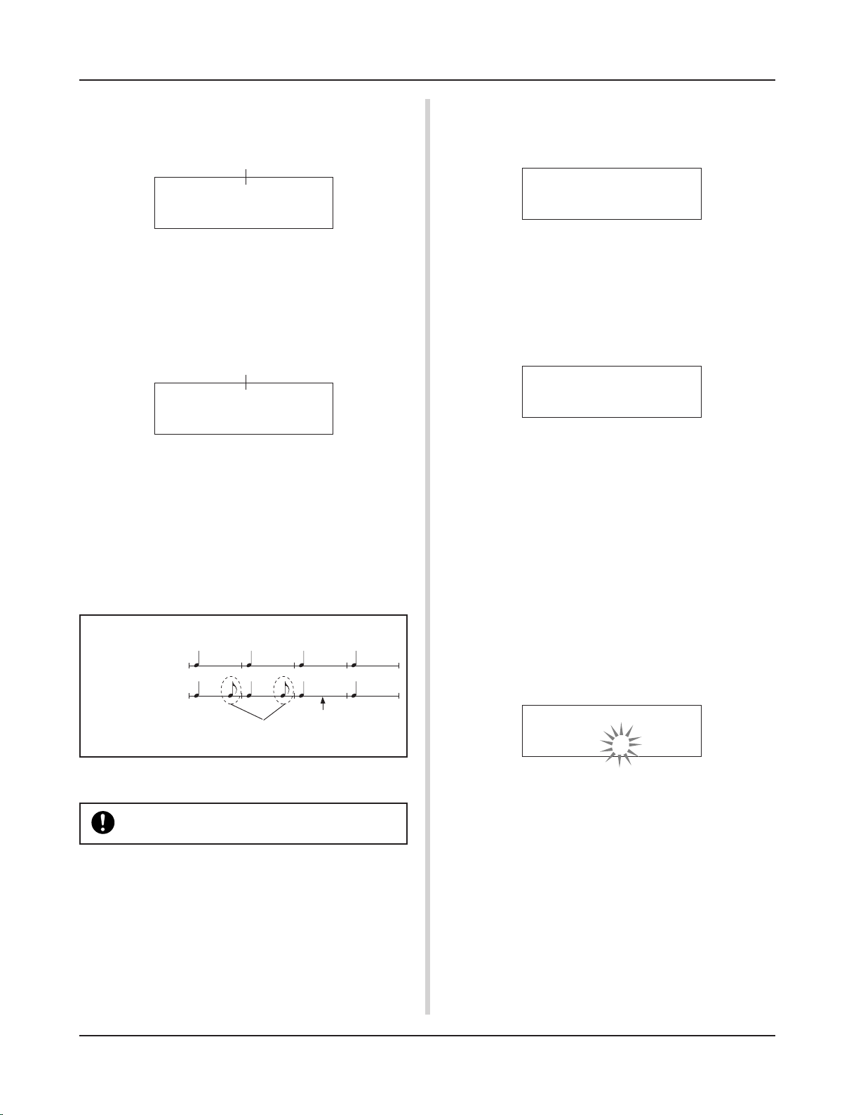
● When the Record Mode is set to Replace (“Rpl”).
The following display will appear while recording (only displayed, cannot be changed).
• To clear song data (both tracks 1 and 2).
Hold the [SHIFT] button and press the [SONG] button to enter the Song Edit mode. Then press the [PAGEt] button 7
times to enter the Clear Song display.
Record Your Performance
When the end of the assigned measure number is reached, recording will automatically stop, and the display will return to
the Song select display.
* You can also stop recording by pressing the [>/■] button.
● When the Record Mode is set to Overwrite (“Ovr”).
The following display will appear while recording (only displayed, cannot be changed).
REC M= 18=Rp1†=1
Now Recording.
The measure number currently being recorded.
The song being recorded will continuously repeat until the [>/
■] button is pressed.
When the song reaches the end of the last measure, it will
automatically start again from the beginning and new data will
be added to the track’s previous data.
When the record mode is set to Overwrite (“Ovr”), press the
[SAVE/ENT] button while recording to “undo” (do again) the
record operation. The data previously recorded from the beginning of the song, up until the [SAVE/ENT] button was
pressed, will revert to the data originally present.
The measure number currently being recorded.
REC M= 18=Ovr†=1
UNDO press ENT
Press the [>/■] button to stop recording, the display will re-
turn to the Song select display.
If the power is cut off during recording, all user song
data may be lost. Please use caution.
4. Listen to the Song
Press the [>/■] button, playback of the song you just recorded
will start from its beginning. You can also change the drum kit
and playback the song with a different kit.
m Reference Guide : P. 24 [2. Program Change, Bank Select]
5. Redo the Recording
To record again, use the following procedure to clear previously recorded data in the track, then try recording again.
● How the “Undo” Works (an example)
Data recorded
the first time.
Data recorded
the second time.
Pressing the [SAVE/ENT] button here, only the
data recorded the second time will be erased.
Press the [SAVE/ENT] button, all of the data in the currently
selected song will be cleared.
* To cancel the “Clear Song” operation, press the [VALUE–]
button.
• To clear data from one track.
Hold the [SHIFT] button and press the [SONG] button to enter the Song Edit mode. Then press the [PAGEt] button 5
times to enter the Clear Track display.
Use the [VALUE–]/[VALUE+] buttons to set the number of
the track you want to clear, then press the [SAVE/ENT] button, “Are
you sure ?” will appear in the display. Press
the [SAVE/ENT] button again, all of the data in the currently
assigned track of the selected song will be cleared.
* To cancel the “Clear Song” operation, press the [VALUE–]
button.
6. Record One More Track
In the same manner, one more track can be used to record.
However, the number of measures cannot be changed.
7. Give the Song a Name
On the display, “no
name” will appear for the song name.
Change the name to an original name.
Hold the [SHIFT] button and press the [SONG] button to enter the Song Edit mode. Then press the [PAGEt] button 8
times to enter the Song Name setting display.
Use the [SEL<]/[SEL>] buttons to move the flashing cursor
to the character you want to change, then use the [VALUE–]/
[VALUE+] buttons to select the desired character.
The available characters to choose from are listed below.
(in order)
Space
!"#$%&'()*+,-.0123456789:;<=>?@
ABCDEFGHIJKLMNOPQRSTUVWXYZ[\]^_`
abcdefghijklmnopqrstuvwxyz{|}ßå
A maximum of 8 characters can be used for the song name.
If the power is switched off, the completed
song will be stored.
SONG Clear Song
Are you sure ?
SONG Clear Track
Track=1
SONG
SngName=no
name
22
You can assign voices you like to each of the pads, and set the tuning (pitch), voice,
decay, reverb, etc. to create your own original drum kit.
2. Try Changing the Volume
Let’s change the volume of the drum voice that is delivered when
the pad is hit. Adjust the volume balance between the other pads.
Press the [PAGEt] button and the following display will appear.
Create Your Own Original Drum Kit
1. Select the Drum Voice
First, select a drum voice for the kit you want to create. Let’s
try assigning a snare drum voice.
It doesn’t matter what drum kit you select (the drum kit that is
created will be saved to a user drum kit (No. 49-80)).
1-1. Select a Snare Drum for the Input Source.
Press the [VOICE] button and the display for selecting the
Drum Voice will appear.
Input Source Layer Number
Use the [SEL<]/[SEL>] buttons to move the flashing cursor
to the input source position, then use the [VALUE–]/[VALUE+]
buttons to select “snare”. This means that the snare pad input that is connected to trigger input jack 2 SNARE is selected.
The value “V=1” indicates that the layer number=1. Two voices
can be delivered (2 layer) with one input source (trigger input). In this case, you will have to assign which voice will be
used here.
1-2. Select the Drum Voice Category.
Next, decide the drum voice category.
The drum voice category is the same category that was used in
the Metronome Click Voice (P. 19).
For this example, let’s select “s: Electric Snare”.
Use the [SEL<]/[SEL>] buttons to move the flashing cursor
to the voice category position, then use the [VALUE–]/
[VALUE+] buttons to select “s”.
A “*” mark will appear between “KIT” and “IN”. This is to
let you know that data in the currently selected drum kit has
changed.
1-3. Select the Drum Voice.
Next, let’s select a drum voice.
Using the same procedure you used when you changed the
metronome click voice (P. 19), press the [SEL>] button to
move the flashing cursor to the Voice Number position, then
use the [VALUE–]/[VALUE+] buttons to assign the drum
voice. For this example, let’s select “014
Dance01”.
KIT IN=kick V=1
=K/017
BDaftty1
Voice Category Voice Number Voice Name
With this, we have assigned a drum voice for the kit
you want to create.
Now, let’s try to edit this drum voice in several ways
and create your own original snare drum voice.
KIT IN=snare V=1
=s/014
Dance01
KIT*IN=snare V=Vol=
120 Pan= C
Volume Pan
Use the [SEL<]/[SEL>] buttons to move the flashing cursor
to the volume level position, then use the [VALUE–]/
[VALUE+] buttons to set the volume level.
*“V=-“ appears when the drum voice is not a 2 layer voice.
Press the [VOICE] button to monitor the voice just as
if the pad were hit.
3. Try Changing the Pan
Using the same display, you can change the pan setting for the
drum voice.
According to this setting you can move the position of the
currently selected drum voice within the stereo field as follows: “L64” (left side) – “C” (Center) – “R63” (right side).
Press the [SEL>] button to move the flashing cursor to the
pan level position, then use the [VALUE–]/[VALUE+] buttons to set the pan value.
4. Try Changing the Tuning (Pitch)
Let’s try and change the tuning (pitch) of the drum voice.
Press the [PAGEt] button and the following display will appear.
KIT*IN=snare V=Tune
C= 0 F= 0
Tuning in half-step increments
Use the [SEL<]/[SEL>] buttons to move the flashing cursor
to the “C” or “F” position, then use the [VALUE–]/[VALUE+]
buttons to set the pitch of the voice.
Tuning for “C=” is in increments of a half-step, tuning for
“F=” is in steps of approximately 1.17 cents.
5. Try Changing the Decay (the length of time
it takes for the voice to fade)
Let’s try and change the voice’s decay (the length of time it
takes for the voice to fade).
Press the [PAGEt] button twice and the following display
will appear.
Finer tuning
KIT*IN=snare V=Decay=+
8 Fc= 0
Decay
Filter Cutoff Frequency

23
Use the [SEL<]/[SEL>] buttons to move the flashing cursor
to the decay value position, then use the [VALUE–]/[VALUE+]
buttons to set the amount of decay.
A + (plus) value will produce a faster decay.
6. Try Changing the Character of the Voice
(Filter Setting).
Using the same display you can set the Filter Cutoff Frequency.
Try to change the character of the voice (the brightness of the
voice).
Press the [SEL>] button to move the flashing cursor to the
“Fc=” position, then use the [VALUE–]/[VALUE+] buttons
to set the value.
A + (plus) value will produce a brighter sound.
7. Try Adjusting the Volume Balance of the 2
Layer Voice.
If the selected drum voice is made with 2 layers (1 drum voice
made with 2 voice waves), the volume balance can be adjusted
between the 2 waves.
Press the [PAGEs] button and the following display will appear.
10. Save the Voice You Have Created
Let’s save the drum voice you created to the DTXPRESS II’s
memory. Drum kit numbers “49” – “80” (these are called user
drum kits) are used for saving individual drum kits.
Press the [SAVE/ENT] button, the following display will appear.
Create Your Own Original Drum Kit
Use the [SEL<]/[SEL>] and [VALUE–]/[VALUE+] buttons
to select the layer number.
* If the assigned voice is not made of 2 layers this setting is
not valid.
Press the [SEL>] button to move the flashing cursor to the
layer balance position, then use the [VALUE–]/[VALUE+]
buttons to set the layer balance value.
8. Adjust the Amount of Reverb.
Let’s try and adjust the amount of reverb effect that is applied
to the voice.
Use the [PAGEs]/[PAGEt] buttons to select the display
shown below.
KIT*IN=snare V=1
LayerBalance=+20
Layer Balance
Layer Number
Use the [SEL<]/[SEL>] buttons to move the flashing cursor
to the reverb send level position, then use the [VALUE–]/
[VALUE+] buttons to set the value.
Large values will increase the amount of reverb applied to the
voice, “0” will produce no reverb.
* This setting is the reverb level for each input source. The
overall reverb level for the drum kit is set in [5-2. Drum Reverb Send] (Reference Guide : P. 23)
9. Adjust the Balance Between Layer 1 and 2.
If you have used a 2 layer voice in the voice you just created,
adjust the balance between the voices by adjusting the volume
of each voice.
*
You can select the conversion curve for 2 voices. m
Drum Kit Edit Mode [2-1. Cross Fade] (Reference Guide : P. 19)
KIT*IN=snare
Reverb
send= 40
Reverb send level
Use the [VALUE–]/[VALUE+] buttons to set the drum kit number (“49” – “80”) for saving your drum kit to.
Press the [SAVE/ENT] button, “Are
you sure ?” will
appear on the display asking for confirmation.
* To cancel the save operation, press the [VALUE–] button.
Press the [SAVE/ENT] button again, the save operation will
be carried out, then “Complete!” will appear. After “Com-
plete!” appears, the display will return to the Drum Voice
select display.
11. Give Your Drum Kit a Name
The completed drum kit will still have the original drum kit’s
name.
Press the [VOICE] button to enter the Drum Kit Voice Edit
mode, then press the [PAGEt] button to display the Drum
Kit Name setting display shown below. With the same procedure you used when you made a Song, give your drum kit an
original name. (P. 21)
Store Drumkit
=49
User Kit
Now the drum kit with the original snare drum
you created is complete.
Use the same procedure to create drum voices
for the other pads (input source) and create a
complete drum kit that is all your own.
The DTXPRESS II also has keyboard voices that comply
with the GM System Level 1. So, not only drum voices, but
piano, guitar, bass, strings, brass, reeds, effect, etc. can be
delivered when the pad is struck.
To use keyboard voices with the pads first, change the pad’s
MIDI channel to any channel other than “10” (Reference
Guide : P. 18 [1-7. Channel, Gate Time]), then select the
MIDI note number of the voice you want to use in (Reference Guide : P. 18 [1-6. Note Number] )
* If the [2-5. Key Off Enable] (Reference Guide : P. 20) is set
to “disable”, some voices may sound continuously. In
this case, press the [SHIFT] + [VOICE] buttons to stop
voices sounding.
KIT Common
Kit=Acoustic
Kit
24
There is much more to the DTXPRESS II than what we have covered so far.
With a full understanding of these functions you can get the most out of the DTXPRESS II.
• Switch the signals between trigger input jacks 1 and 9/10
m Reference Guide : P. 14 [2-2. Input Exchange]
• Copy trigger setup data from one trigger input jack’s setup to
another
m Reference Guide : P. 13 [1-6. Trigger Setup Copy]
• Temporarily prohibit reception of trigger signals from all pads
connected to the DTXPRESS II
m Reference Guide : P. 29 [2-2. Trigger Bypass]
Switch the trigger bypass function (above) ON/OFF from a
pad.
m Reference Guide : P. 20 [2-6. Function]
■ Set the Reverb
The DTXPRESS II is equipped with a digital reverb section.
• Set the reverb type and reverb time for each drum kit
m Reference Guide : P. 21 [3-1. Reverb Type, Time]
• The following three methods can be used to set the amount of
reverb.
Adjust the reverb level for the voice delivered by the pad of each
input source,
m Reference Guide : P. 19 [2-2 Reverb Send]
Adjust the reverb send level for the entire drum kit,
m Reference Guide : P. 23 [5-2. Drum Reverb Send]
Adjust the DTXPRESS II’s overall reverb send level,
m Reference Guide : P. 21 [3-2. Reverb Master Return]
Adjust the amount of reverb for each drum kit in the user drum
map
m Reference Guide : P. 36 [5-6. Reverb Send]
• Bypass the reverb circuit (no reverb).
m Reference Guide : P. 28 [1-5. Reverb Bypass]
■ Settings related to the Drum Voice
• Set the cross fade between voice layers 1 and 2.
m Reference Guide : P. 19 [2-1. Cross Fade]
• Set the rim voice to simultaneously trigger the pad voice when
stereo pads are used.
m Reference Guide : P. 21 [2-8. Rim to Pad]
• Set the alternate group and key assign mode for voices that are
delivered simultaneously.
m Reference Guide : P. 19 [2-3. Alternate Group, Key Assign Mode]
• Set the key ON/OFF that is transmitted when the pad is hit.
m Reference Guide : P. 20 [2-4. Hold Mode]
• Set whether to recognize or not key off messages.
m Reference Guide : P. 20 [2-5. Key Off Enable]
Getting More Out of Your DTXPRESS
II
■ Factory Set
The internal settings of the DTXPRESS II will be returned to their
factory preset condition.
m Utility Mode [2-6. Factory Set] (Reference Guide : P. 30)
If the factory set operation is carried out, data for
the User Drum Kit, User Trigger Setups and User
Songs will be lost.
■ Functions related to connections and input
source (pads)
• Drum kits can be selected by hitting a pad. For example, with
an optional Yamaha Bar Pad BP80 connected to the trigger
input jack 9/10, you can hit the left bar pad to decrease the
value of the drum kit number by 1. Likewise, hitting the right
bar will increase the value of the drum kit number by 1.
When the function described above is used in any drum kit
m Reference Guide : P. 14 [2-1. Increment/Decrement]
When the function described above is used in a specified drum
kit.
m Reference Guide : P. 20 [2-6. Function]
• A hi-hat controller connected to the trigger input jack 1 KICK
can be used as a KICK pedal.
m Reference Guide : P. 12 [1-1. Pad Type]
• Several methods are available for adjusting the sensitivity of
pads and drum triggers.
To automatically set suitable settings for pads and drum triggers
connected to the DTXPRESS II
m Reference Guide : P. 12 [1-1. Pad Type]
To greatly modify the sensitivity,
m Change the INPUT ATTENUATION switch on the rear panel. (P.
10)
For minor adjustments to the sensitivity,
m Reference Guide : P. 12 [1-2. Gain, Minimum Velocity]
• Set the sensitivity of the hi-hat controller connected to the HI
HAT CONTROL jack.
m Reference Guide : P. 23 [5-3. Hi-hat Sensitivity]
• Set the point at which the hi-hat controller “closes” the hi-hat
and the amount of time it takes to detect a foot splash
m Reference Guide : P. 30 [2-5. Hi-Hat Offset]
• Eliminate cross-talk (mixed input signals between the jacks)
m Reference Guide : P. 13 [1-4. Self Rejection/Rejection]
m Reference Guide : P. 13 [1-5. Specified Rejection]
• Eliminate double-triggers (2 sounds played at the same time)
m Reference Guide : P. 13 [1-4. Self Rejection/Rejection]
• Set the velocity curve that determines the relationship between
the strength that the pad is hit and the volume that is produced
m Reference Guide : P. 13 [1-3. Velocity Curve]
25
■ Settings Related to the Tone Generator
• The following settings will have an effect over the entire tone
generator.
Equalizer (adjust the tone quality), Tuning, Volume, Reverb Bypass
m Reference Guide : P. 28 [1. TG (Tone Generator) Group]
■ Settings Related to the Song
• Automatically switch the main song when the drum kit is
switched.
m Reference Guide : P. 23 [5-4. Song Select]
• Control the simultaneous playback (start/stop) of up to 3 songs
by hitting the pad.
m Reference Guide : P. 20 [2-7. Pad Song]
• Edit the following parameters in song sequencer data
Tempo, Repeat Playback, Program Change, Bank Select, Volume, Pan, Song Copy, Quantize, Clear Track, Merge Track,
Clear Song and Song Name
m Reference Guide : P. 24 [Song Job Mode]
• Playback the song at the set tempo, even when the song is
switched.
m Reference Guide : P. 35 [4-7. Use Tempo]
■ Other Functions
• Along with triggering voices the pads can be used for a variety
of control functions.
Pad song playback/stop, metronome’s click voice ON/OFF, switch
drum kits, trigger bypass ON/OFF and playback/stop of the main song.
m Reference Guide : P. 20 [2-6. Function]
• Assign pads (trigger input source) in the Trigger Setup Edit
mode and Drum Kit Voice Edit mode simply by hitting the
pad.
m Reference Guide : P. 29 [2-1. Learn Mode]
• Adjust the volume of the cymbal, drum and other instruments
using the ACCOMP. VOL. knob and CLICK VOL. knob.
m Reference Guide : P. 29 [2-3. Volume Mode]
• Display the page that was previously used in the Trigger Setup
Edit mode and Drum Kit Voice Edit mode.
m Reference Guide : P. 29 [2-4. Jump to Recent Page]
■ Using MIDI
The DTXPRESS II is equipped with MIDI IN/OUT jacks and a
TO HOST jack. These jacks are used to exchange data between an
external MIDI device/computer and the DTXPRESS II. The MIDI
data format is used.
About MIDI
MIDI (Musical Instrument Digital Interface) is a world standard that provides a means to connect instruments and computers and allow them to transmit and receive performance
and other data. This standard allows computers and instruments of different makers and types to communicate.
Using MIDI the DTXPRESS II can perform the following operations. Refer to the [Connecting a MIDI Device] section (P. 12) for
more information on connecting external MIDI devices.
● Bulk Dump/Bulk In
Data for each of the settings in the DTXPRESS II can be transmitted to an external MIDI device or computer (Bulk Dump). When
connected to the DTXPRESS II, a device equipped with a “save”
function, such as the Yamaha MDF3, etc., can be used to backup
your data and create a library with.
Also, the data saved in an external device can be transmitted back
to the DTXPRESS II (Bulk In).
● Synchronized Playback with External MIDI
Devices
When two MIDI devices that use tempo information such as a
sequencer, etc. are connected, one device must play along with the
other (sync) using tempo information (clock) transmitted by the
master device.
Playback of an external sequencer’s data can be synchronized with
the DTXPRESS II’s song and metronome click. Also, playback of
the DTXPRESS II’s song can be synchronized to an external sequencer.
● Transmit and Receive MIDI Data
• The DTXPRESS II’s tone generator can be driven by MIDI
song data (sequence data) transmitted from an external MIDI
device. This song data can be recorded along with your performance on the DTXPRESS II.
• The DTXPRESS II’s drum kits can be switched and song playback can be controlled from an external MIDI device.
• Hi-hat controller information can be transmitted via MIDI.
A variety of other MIDI information can also be transmitted and
received.
Refer to the [Drum Kit Voice Edit Mode] (P. 15), [Utility Mode]
(P. 27), [MIDI Data Format], (P. 50) etc. in the “Reference Guide”
for more information.
Getting More Out of Your DTXPRESS
II
• Set the volume of the entire drum kit.
m Reference Guide : P. 23 [5-1. Volume]
• Create an original drum kit.
m Reference Guide : P. 35 [5. MAP (Drum Map Group)]
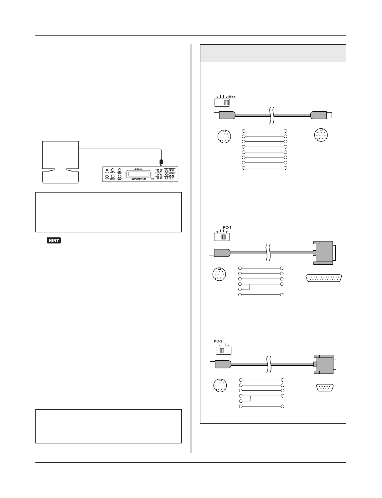
26
■ Connecting a Computer
The following two methods are available for connecting the
DTXPRESS II to a computer.
1. Directly connect the computer’s serial port to the
DTXPRESS II’s TO HOST jack.
2. Connect the DTXPRESS II’s MIDI IN jack to the computer through a MIDI interface.
1. Directly connect the serial port to the TO HOST jack.
The method used for connect and transferring signals between a
computer and the DTXPRESS II is basically the same, no matter
what type of computer is used.
Getting More Out of Your DTXPRESS
II
Use a cable to connect the devices and set the HOST SELECT SWITCH according to the type of computer serial
port and clock used. Carefully read the instructions on
the right side of this page and select an appropriate cable
for the type of computer you are using.
The input signal from the TO HOST jack will be transmitted to the DTXPRESS II’s tone generator and sequencer, and simultaneously transmitted to the
DTXPRESS II’s MIDI OUT jack. At this time, only
message for the port number that is set in the Utility
mode’s [3-10. Host Thru Port] (Reference Guide : P.
33) will be sent to the MIDI OUT jack.
The signal from the tone generator and sequencer is
merged with the signal from the MIDI IN jack and
output to the TO HOST jack.
2. Connect the MIDI IN Jack to a MIDI Interface
• If you are using a computer equipped with a MIDI interface,
connect the MIDI OUT jack on the computer to the MIDI IN
jack on the DTXPRESS II. Set the HOST SELECT switch to
the “MIDI” position.
• If you are using a Macintosh series computer with an external
MIDI interface, connect the MIDI interface to the computers
RS-422 jack (modem or printer port), connect the MIDI OUT
jack on the interface to the MIDI IN jack on the DTXPRESS
II. Set the HOST SELECT switch to the “MIDI’ position.
* When the HOST SELECT switch is set to the “MIDI” position, the
transmission and reception via the TO HOST jack is ignored.
Computer
Serial Port
Serial Cable
TO HOST
DTXPRESS II
Computer Connecting Cables
● Mac
Apple Macintosh Peripheral cable (M0197).
Maximum length 2 meters.
mini DIN 8-pin mini DIN 8-pin
2 (HSK i)1
1 (HSK o)2
5 (RxD _)3
4 (GND)4
3 (TxD _)5
8 (RxD +)6
7 (GP i)7
6 (TxD +)8
● PC-1
8-pin MINI DIN to D-SUB 25-pin cable.
If your PC-1 type computer has a 9-pin serial port, use the
PC-2 type cable. Maximum length 1.8 meters.
D-SUB 25-pin
mini DIN 8-pin
5 (CTS)1
4 (RTS)2
3 (RxD)3
7 (GND)4
8
2 (TxD)5
● PC-2
8-pin MINI DIN to D-SUB 9-pin cable.
Maximum length 1.8 meters.
8 (CTS)1
7 (RTS)2
2 (RxD)3
5 (GND)4
8
3 (TxD)5
mini DIN 8-pin
D-SUB 9-pin
If you are using a computer equipped with a USB port,
you can connect the DTXPRESS II to your computer via
a USB-MIDI interface such as the YAMAHA UX16/96/
256, etc.

27
Specifications
Tone Generator 16 bit AWM2
Maximum polyphony 32
Voices 928 drum, percussion voices and effects
128 keyboard voices (GM system level 1)
Drum kits 48 Preset
32 User memory locations
Trigger setups 5 Preset
4 User memory locations
Sequencer tracks 2 (TR1, TR2)
Song control
Main song Start/Stop, note chase
Pad song 3 songs can be played at the same time, Trigger Control
Other Sequencer Functions MIDI sync play, Quantize (while recording, in Song Edit job mode),
Mute (rhythm mute, drum instrument mute), Groove Check
Song 95 Preset
32 User memory locations
Record modes Real-time
Controls
LED buttons 6 (DRUMKIT, SONG, TRIG, VOICE, UTIL, CLICK)
Buttons 9 (START/STOP, SAVE/ENTER, SHIFT, PAGEs/t, SELECT </>, VALUE–/+
Knobs MASTER VOLUME/POWER SW (push), ACCOMP. VOLUME, AUX VOLUME,
CLICK VOLUME
Display 16 x 2 LCD display (w/Back light)
Connections
Front Panel Aux input (stereo mini jack)
Head phone (stereo phone jack)
Rear Panel MIDI input/output
Foot controller (stereo phone jack)
HOST SELECT SW
TO HOST (mini DIN jack)
Output L/MONO (mono phone jack)
Output R (mono phone jack)
Trigger Inputs 1 – 8 (stereo phone jackmL : trigger input, R : rim switch)
Trigger Input 9/10 (stereo phone jackmL, R : trigger input)
Trigger attenuation switch 1-6 (DIP SW)
Power supply DC 12V/AC adaptor (PA-3B or PA-3C)
Power Requirement 4.8 Watt
Dimensions (W x H x D) 220 x 240 x 44 mm (8-11/16” x 9-3/16” x 1-5/16”)
Weight 1.6 kg (3 lbs 8 oz)
Accessories Owner’s Manual (Basic, Reference)
AC adaptor
* Specifications and descriptions in this owner’s manual are for information purposes only.
Yamaha Corp. reserves the right to change or modify products or specifications at any time without prior notice. Since specifications, equipment or options
may not be the same in every locale, please check with your Yamaha dealer.
28
Error Messages
An Error Message will appear when incorrect settings or operation are detected, or abnormal operation occurs.
Check the Error Message below and make the appropriate corrections.
This message appears just after the power is switched on and the device can not
correctly read the data. The cause of the problem may be that the backup RAM data
has been damaged or the backup battery power is low. Contact the nearest Yamaha
Service Center or the dealer where you purchased the device.
The internal memory backup battery power is too low. User data may be deleted.
Contact the nearest Yamaha Service Center or the dealer where you purchased the
device.
Too much MIDI data is being received at one time and the device could not manage
the data. Reduce the amount of data being sent at one time and try again.
The computer connected to the device is either turned off or not correctly connected.
Check cable connections and the power and try again.
The check sum for the data received is incorrect. Check the check sum of the data
being transmitted.
An error occurred while data was being received. There may be abnormalities in the
data being sent. Check the data being transmitted.
This message is displayed when you try to edit preset song.
Preset song cannot be edited.
The operation can’t be performed while the sequencer is running. Stop the sequencer
and try again.
This message appears if you try to record to a track containing data. Select an empty
track and try recording again.
You have exceeded the memory capacity of the user song. Delete unwanted songs
to make more memory available and try recording again. At this time, use the bulk
dump function to move any songs you wish to keep to an external MIDI device.
ERROR
Data
Initialized
WARNING
Battery
Low
ERROR
MIDI
Buffer full
ERROR
HOST
is OffLine
ERROR
Check
Sum Error
ERROR
Illegal
Data
CAN'T EDIT
PRESET
SONG
ERROR
SEQ
is Running
ERROR
Data
not Empty
ERROR
Memory
Full

29
Trouble Shooting
The DTXPRESS II does not produce sound, and does not recognize trigger inputs.
● Is the pad or trigger sensor properly connected to the DTXPRESS II’s trigger input jack? (m P. 10)
● Is the volume knob on the front panel turned down? (m P. 8)
● Is the input level displayed when the pad is hit? (m Reference Guide : P. 12 [1-2. Gain, Minimum Velocity])
● Is the gain set too low? (m Reference Guide : P. 12 [1-2. Gain, Minimum Velocity])
● Is the Utility mode’s [2-2. Trigger Bypass] bypass switch set to “ON”? (m Reference Guide : P. 29)
● Is the Drum Kit Voice Edit mode’s [1-2. Volume, Pan] (m Reference Guide : P. 17) or [5-1. Volume] (m Reference
Guide : P. 23) volume set to “0”?
● Check the local control setting in the Utility mode. When the local control is set to “off” the DTXPRESS II will not
produce sound when the pads are hit. (m Reference Guide : P. 32 [3-6. Device Number, Local Control])
● Is the cable you are using OK?
The external tone generator does not produce sound.
● Is the MIDI cable (connector) properly connected? (m P. 12)
● Are the MIDI note number values proper? (m Reference Guide : P. 18 [1-7. Channel, Gate Time])
● Is the Utility mode’s [2-2. Trigger Bypass] bypass switch set to “ON”? (m Reference Guide : P. 29)
A voice other than the set voice is produced.
● Is the transmitting MIDI channel set to a channel that is not used for the drum voice (ch=10)? (m Reference Guide
: P. 18 [1-7. Channel, Gate Time])
● Is the Voice=2 parameter set for a 2 layer voice? (m Reference Guide : P. 17 [1-1. Voice])
Produces sound but the sensitivity is too low (volume is low).
● Is the gain set too low? (m Reference Guide : P. 12 [1-2. Gain, Minimum Velocity])
● Pads with output or sensitivity control volumes should be adjusted (increased).
● Is the minimum velocity set too low? (m Reference Guide : P. 12 [1-2. Gain, Minimum Velocity])
● Is a proper velocity curve being used? (m Reference Guide : P. 13 [1-3. Velocity Curve])
● Is the volume of the voice you want to use too low? (m Reference Guide : P. 17 [1-2. Volume, Pan])
● Is the drum head getting old?
● Change the INPUT ATTENUATION setting on the rear panel. (m P. 9 )
The trigger sound is not stable (for acoustic drums).
● Check the “Produces sound but the sensitivity is too low (volume is low).” list above.
● Is the proper pad type set? Select a larger pad type setting (DT snare m DT hi tom m DT lo tom m DT kick 1 m
DT kick 2) (m Reference Guide : P. 12 [1-1. Pad Type])
● Is the DT20 properly attached with sticky tape? (Is there any old sticky tape remaining on the head?) (m P. 11)
● Is the cable securely connected to the DT20 jack?

30
Trouble Shooting
Double-triggers (when 2 sounds are played at the same time) are produced.
● Are you using a sensor made by a manufacturer other than Yamaha? If the signal is too large, double-triggers may
be produced.
● Is the head causing irregular vibrations? It may be necessary to mute the head.
● Is the sensor attached close to the center of the head? Move the sensor closer to the rim (above the bearing).
(m P. 11)
● Is the sensor in contact with anything else?
● Pads with output or sensitivity control volumes should be adjusted (lowered).
● Try increasing the rejection parameter. However, a setting a value that is too high may cause the sound to be
muted when another drum is hit at the same time. (m Reference Guide : P. 13 [1-4. Self-Rejection, Rejection])
● Use the self-rejection. (m Reference Guide : P. 13 [1-4. Self-Rejection, Rejection])
● Change the INPUT ATTENUATION setting on the rear panel. (m P. 9)
Cross-talk (mixed signals from different inputs) is produced.
● Try placing the sensors (DT20, etc.) away from nearby drums.
● Is the gain set too high? (m Reference Guide : P. 12 [1-2. Gain, Minimum Velocity]).
● Try increasing the rejection parameter. However, a setting a value that is too high may cause the sound to be
muted when another drum is hit at the same time. (mReference Guide : P. 13 [1-4. Self-Rejection, Rejection])
● If cross-talk is produced with a specific trigger input, try using specific rejection. (m Reference Guide : P. 13 [1-5.
Specific Rejection])
Sounds are cut when you play continuously.
● The maximum polyphony of 32 voices might be exceeded. In the Drum Kit Voice Edit mode’s [2-3. Alternate
Group, Key Assign Mode] (m Reference Guide : P. 19) set the “Key” value to “semi” or “mono”.
When 2 pads (drums) are played only 1 sound is heard.
● Raise the gain setting of the pad (drum) that is not producing sound. (m Reference Guide : P. 12 [1-2. Gain,
Minimum Velocity])
● Lower the rejection setting of the pad that is not producing sound. (m Reference Guide : P. 13 [1-4. Self-Rejection,
Rejection])
● Are both pads assigned to the same group in the Drum Kit Voice Edit mode’s [2-3. Alternate Group, Key Assign
Mode] display (m Reference Guide : P. 19)?
The sound is always loud.
● Is the minimum velocities minimum value set too high? (m Reference Guide : P. 12 [1-2. Gain, Minimum Velocity])
● Are you using a proper velocity curve? (m Reference Guide : P. 13 [1-3. Velocity Curve])
● Are you using a sensor made by a manufacturer other than Yamaha? Depending upon the manufacturer output
levels might be too large.
● Change the INPUT ATTENUATION setting on the rear panel. (m P. 9)
The DTXPRESS II does not receive any switch or trigger signals.
● If you can access the Utility mode, do a factory reset. The DTXPRESS II will reset to its factory settings. (m
Reference Guide : P. 30 [2-6. Factory Set])
● Turn the [POWER SW] OFF then ON while holding the [PAGEs] and [PAGEt] buttons. The DTXPRESS II will
reset to its factory settings.
The sound will not stop.
● Some voices have very long release times when the [2-5. Key Off Enable] (m Reference Guide : P. 20) “key off”
parameter is set to “disable”. To temporarily stop the sound, hold the [SHIFT] button and press the [VOICE] button.
 Loading...