

DRUM TRIGGER MODULE
English
Français
Deutsch
Owner’s Manual / Reference Guide
Mode d’emploi / Guide de référence
Bedienungsanleitung / Referenzhandbuch
Manual de instrucciones / Guía de referencia
Español
CONTENTS
How to use the Manual
The DTXPRESS Owner’s Manual is divided into the following two books.
● Basic Guide
Please read this book before using the
DTXPRESS.
This book contains cautions that must be followed for
safe and proper use of the DTXPRESS.
Also, control and function names, connecting the pads
and how to play the DTXPRESS, how to record and
playback songs, how to create original drum kits are
all described in this book.
At the rear of this book you will find an appendix section with specifications and error messages.
● Reference Guide (this book)
This book describes in detail each of the DTXPRESS’
functions.
At the rear of this book you will find an appendix section with drum voice, song, MIDI data format, etc.
About the descriptions
This manual describes buttons and explanations using the
following rules.
• [PLAY], [START/S], etc.
The button on the front panel is indicated with
[ ]. (brackets).
• [SHIFT]+[START/S], etc.
Means hold the [SHIFT] button and press the [START/
S] button.
•[PAGEs]/[PAGEt], etc.
Means use the [PAGEs] button or [PAGEt] button.
•“Complete!”, etc.
Words inside “ ” indicate the message shown on the
display.
• m P. 10, etc.
Indicates the reference page where further information can be found.
NOTE
The illustrations and LCD screens as shown in this
owner’s manual are for instructional purposes only,
and may appear somewhat different from those on
your instrument.
DTXPRESS Internal Makeup ................ 4
Drum Kit Play Mode .............................. 6
1. Drum Kit & Song .......................................... 6
2. Trigger Setup & Tempo ................................. 6
3. Song & Mute ................................................. 7
Groove Check Function................................... 7
About the Song ..................................... 8
Song Playback.................................................. 8
Song Recording ............................................. 10
Trigger Setup Edit Mode ..................... 11
1. INPUT Parameters ...................................... 12
1-1. Pad Type ....................................................... 12
1-2. Gain, Minimum Velocity ................................ 12
1-3. Velocity Curve ............................................... 13
1-4. Self Rejection, Rejection .............................. 13
1-5. Specific Rejection ......................................... 13
1-6. Trigger Setup Copy ....................................... 13
2. COMMON PARAMETERS........................... 14
2-1. Increment/Decrement ................................... 14
2-2. Input Exchange............................................. 14
2-3. Trigger Setup Name ...................................... 14
Drum Kit Voice Edit Mode ................... 15
1. Voice Parameters ........................................ 16
1-1. Voice ............................................................. 17
1-2. Volume, Pan.................................................. 17
1-3. Tuning ........................................................... 17
1-4. Layer Balance ............................................... 18
1-5. Decay, Cutoff Frequency .............................. 18
1-6. Note Number ................................................ 18
1-7. Channel, Gate Time...................................... 18
2. Input Common Parameters ....................... 19
2-1. Cross Fade ................................................... 19
2-2. Reverb Send ................................................. 19
2-3. Alternate Group, Key Assign Mode .............. 19
2-4. Hold Mode .................................................... 20
2-5. Key Off Enable.............................................. 20
2-6. Function ........................................................20
2-7. Pad Song ...................................................... 20
2-8. Rim To Pad ................................................... 21
2

CONTENTS
3. Reverb Parameter ....................................... 21
3-1. Reverb Type, Time ........................................ 21
3-2. Reverb Master Return ..................................21
4. Setup ........................................................... 22
4-1. Program Change, Bank Select ..................... 22
4-2. Volume, Pan.................................................. 22
4-3. Drum Kit Voice Copy ..................................... 22
5. Drum Kit Common Parameters ................. 23
5-1. Volume ..........................................................23
5-2. Drum Reverb Send ....................................... 23
5-3. Hi-hat Sensitivity ...........................................23
5-4. Song Select .................................................. 23
5-5. Drum Kit Name ............................................. 23
Song Job Mode ................................... 24
1. Tempo, Repeat Playback .................................24
2. Program Change, Bank Select ........................24
3. Volume, Pan .....................................................25
4. Song Copy ....................................................... 25
5. Quantize .......................................................... 25
6. Clear Track ....................................................... 26
7. Merge Track ..................................................... 26
8. Clear Song .......................................................26
9. Song Name ......................................................26
Utility Mode .......................................... 27
1. SYSTEM Group........................................... 28
1-1. Learn Mode .................................................. 28
1-2. Trigger Bypass .............................................. 28
1-3. Volume Mode ................................................ 28
1-4. Jump to Recent Page ................................... 28
1-5. Hi-Hat Offset .................................................29
1-6. Factory Set ...................................................29
2. MIDI Group .................................................. 29
2-1. Bulk dump ..................................................... 29
2-2. Channel 10 Program Change/Channel Event
Receive ........................................................ 30
2-3. Receive Program Change/System
Exclusive Messages ..................................... 30
2-4. Program Change Table ................................. 31
2-5. MIDI Mode .................................................... 31
2-6. Device Number, Local Control ...................... 31
2-7. MIDI Merge ...................................................31
2-8. Dump Interval ............................................... 32
2-9. Send Hi-Hat Control ..................................... 32
2-10. Host Thru Port ............................................32
3. Sequencer Group ....................................... 32
3-1. Click Voice ....................................................32
3-2. Click Tune ..................................................... 33
3-3. Click Note Number ....................................... 33
3-4. MIDI Control ................................................. 33
3-5. Count Switch ................................................ 33
3-6. Sync Mode .................................................... 33
3-7. Use Tempo.................................................... 34
3-8. Click Mode .................................................... 34
4. TG (Tone Generator) Group ....................... 34
4-1. Equalizer (EQ) .............................................. 34
4-2. Tuning ........................................................... 34
4-3. Volume ..........................................................34
4-4. Reverb Bypass .............................................35
5. MAP (Drum Map) Group............................. 35
5-1. Voice ............................................................. 35
5-2. Volume, Pan.................................................. 36
5-3. Tuning ........................................................... 36
5-4. Layer Balance ............................................... 36
5-5. Decay, Cutoff Frequency ............................. 36
5-6. Reverb Send ................................................. 36
5-7. Alternate Group, Key Assign Mode .............. 37
5-8. Key Off Enable.............................................. 37
5-9. Map Copy .....................................................37
Drum Voice List ................................... 38
GM Keyboard Voice List...................... 42
Preset Drum Kit List............................ 42
Preset Song List .................................. 49
Trigger Setup List ................................ 49
MIDI Data Format................................. 50
MIDI Implementation Chart................. 52
Blank Chart .......................................... 53
3
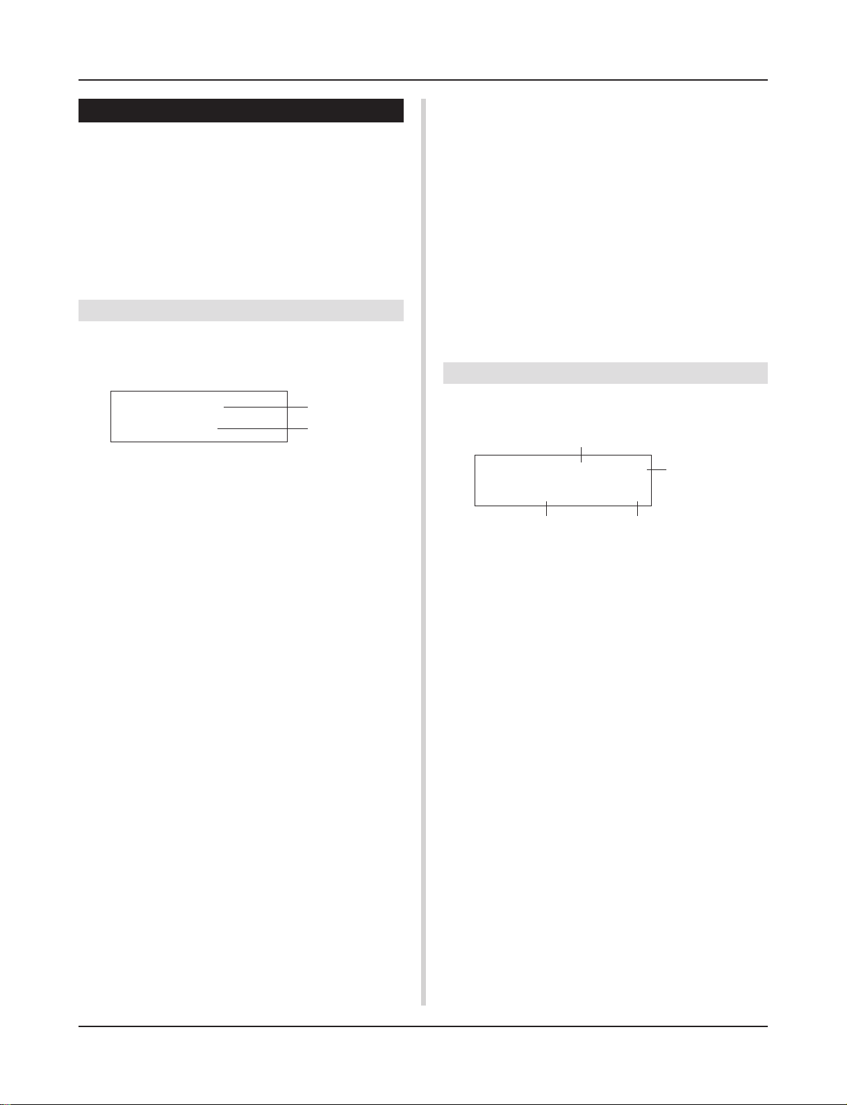
DTXPRESS Internal Makeup
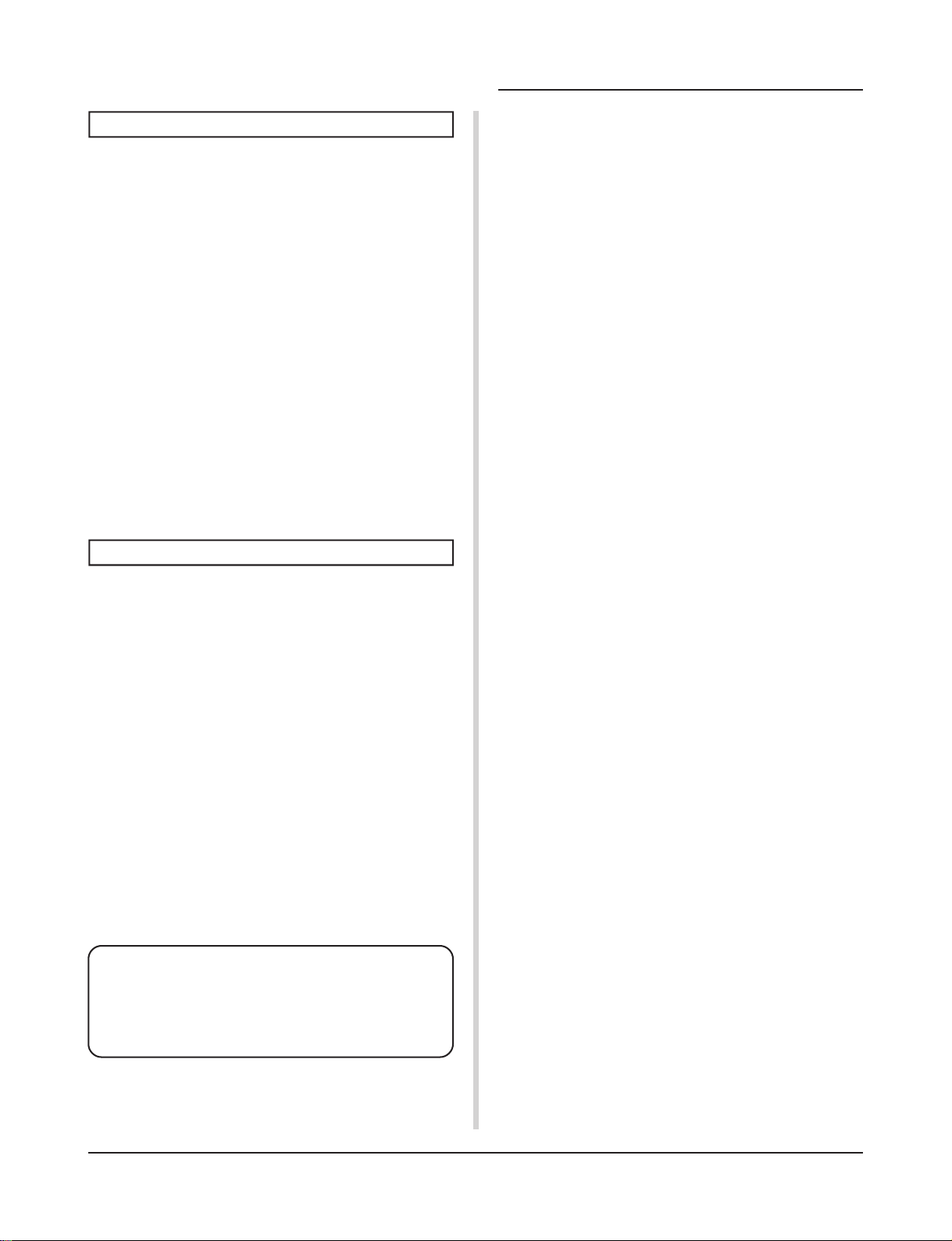
■ The DTXPRESS’ Internal Signal Flow
Sequencer data
from a computer
or an external
MIDI device.
Song Data
Preset
No. 1-95
User
No. 96-127
Record
Drum Kit Data Buffer
Tr ansmits key on/off, program
change, note number, etc.
MIDI data to a computer or an
external MIDI device.
Playback
Input for Trigger Signals produced when the pad is struck
Trigger Setup Data Buffer
Record
Tone Generator
Audio Signal Output
Copy
Copy
Store
The Tone Generator is sounded according to the Drum Maps
for each of the Drum Kits
• Each Preset Drum Kit has its own Drum Map
• User Drum Kits No. 49-80 use a common (one) Drum Map.
Drum Kit Data
Preset
No. 1-48
User
No. 49-80
Trigger Setup Data
Preset
No. 1-7
User
No. 8-11
● Pad Data Signal Flow
In order for the DTXPRESS to effectively manage trigger signals
transmitted from the pads connected to the Trigger Input Jacks (1
KICK, 2 SNARE, … 9/10) and the HI HAT CONTROL jack, trigger signals are adjusted to a suitable signal in the Trigger Setup
Buffer using the Trigger Setup.
Signals transmitted from the Trigger Setup Buffer will enter the
Drum Kit Buffer.
In the Drum Kit Buffer, the Drum Kit is set as to what voices will
be used and how voices will be delivered for each of the Trigger
Input Sources. The Tone Generator’s Voices will be produced
according to these settings and its audio signal will be transmitted
to the OUTPUT jacks and PHONES jack.
● Trigger Setup Data
This mode is used for adjusting the trigger input, from pads and
trigger sensors connected to the Trigger Input Jacks, to a suitable
signal the sensitivity and velocity curve settings. (The signals characteristics will change according to the strength of the hit.) Also,
cross-talk and double-trigger can be effectively eliminated with
the settings available here.
4
Along with 7 preset trigger setups (No. 1-7), there are another 4
user trigger setups (No. 8-11) available for storing original setups.
After selecting a trigger setup for use, the data will be copied to
the Trigger Setup Data Buffer where the copied data will be used
in performance. (Refer to the illustration above.)
Setup data can be freely changed in the Trigger Setup Edit mode
and saved, if necessary, to the User Trigger Setup’s memory (No.
8-11).
● Drum Kit Data
This mode is used for setting drum kit voices, for example, assign
a voice to each pad (trigger input source) used in the drum kit and
perform settings such as selecting the voice, tuning, reverb level,
etc.
The DTXPRESS has 48 preset (No. 1-48) drum kits and another
32 user (No. 49-80) drum kits that are used for saving original
drum kits created by the user.
As in the Trigger Setup, the selected drum kit’s data will be copied
to the Drum Kit Data Buffer where the copied data will be used in
performance. (Refer to the illustration above.) This Drum Kit data
can be freely changed in the Drum Kit Voice Edit mode and saved,
if necessary, to the User Drum Kit’s memory (No. 49-80).
DTXPRESS Internal Makeup
● Tone Generator
The DTXPRESS’ tone generator contains a total of 910 drum and
percussion voices.
Preset Drum Kits use an exclusive Drum Kit Map for each kit in
which voices for the kit are assigned to individual MIDI note numbers.
The User Drum Kit uses one drum map (User Drum Map) that is
common for all drum kit numbers 49-80. The Utility mode’s [5.
Map (Drum Map)] group can be used to assign voices to each
MIDI note number (0-127) and edit the drum kit.
Along with the DTXPRESS’ drum and percussion voices, the
DTXPRESS possesses a variety of keyboard voices (128 voices)
that are based on the GM System Level 1. It is possible to deliver
piano and brass voices by hitting the pad and playback songs with
the internal sequencer or from external sequencer data. A maximum of 32 voices can be delivered simultaneously.
● Song Data
The DTXPRESS contains 95 preset songs (No. 1-95) that consist
of not only drum parts but also keyboard, brass, etc., accompaniment parts.
You can enjoy the songs as they are or mute the song’s drums or a
single drum voice (snare drum, etc.) and play along with the drum.
Also, you can record your performance to the User Song memory
(No. 96-127). Each song consists of two tracks and each track can
include data for MIDI channels 1-16.
● MIDI/TO HOST Jacks
All drum kit setting data and sequencer data are managed with a
MIDI data.
By connecting the DTXPRESS’ MIDI OUT/IN jacks to the MIDI
IN/OUT jacks on an external MIDI device, MIDI data can be exchanged. The TO/HOST jack is used to transmit and receive MIDI
data from a computer.
According to the MIDI data transmitted from an external MIDI
device or computer connected to the DTXPRESS, drum kits can
be switched, the song can be controlled and the tone generator can
be sounded freely.
For example, song data (sequencer data) transmitted from an external sequencer to the DTXPRESS’ MIDI IN jack can be used to
play the voices produced by the DTXPRESS’ internal tone generator. You can use the DTXPRESS to play along with these songs
and record both external sequencer and DTXPRESS parts.
Also, MIDI data produced when the DTXPRESS can be transmitted to an external MIDI device and/or computer. Playing the
DTXPRESS in this configuration allows you to trigger the external tone generator’s voices and when a drum kit is switched, have
the external MIDI keyboard’s voice change as well. The
DTXPRESS’ data can be stored to, as well as retrieved from an
external MIDI device.
■ Basic Operations for Data Setting
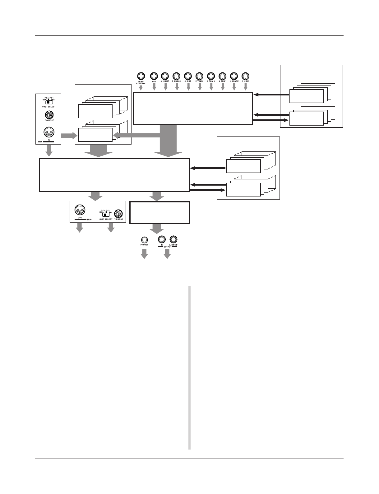
● Enter the Modes
Press each Mode button.
Double-click a button to jump directly to the specified page the
mode you want to enter.
• Drum Kit Play Mode .............................. [PLAY]
• Trigger Setup Edit Mode ....................... [TRIG]
• Utility Mode ........................................... [UTIL]
• Drum Kit Voice Edit Mode .................... [VOICE]
• Song Job Mode ..................................... [SONG]
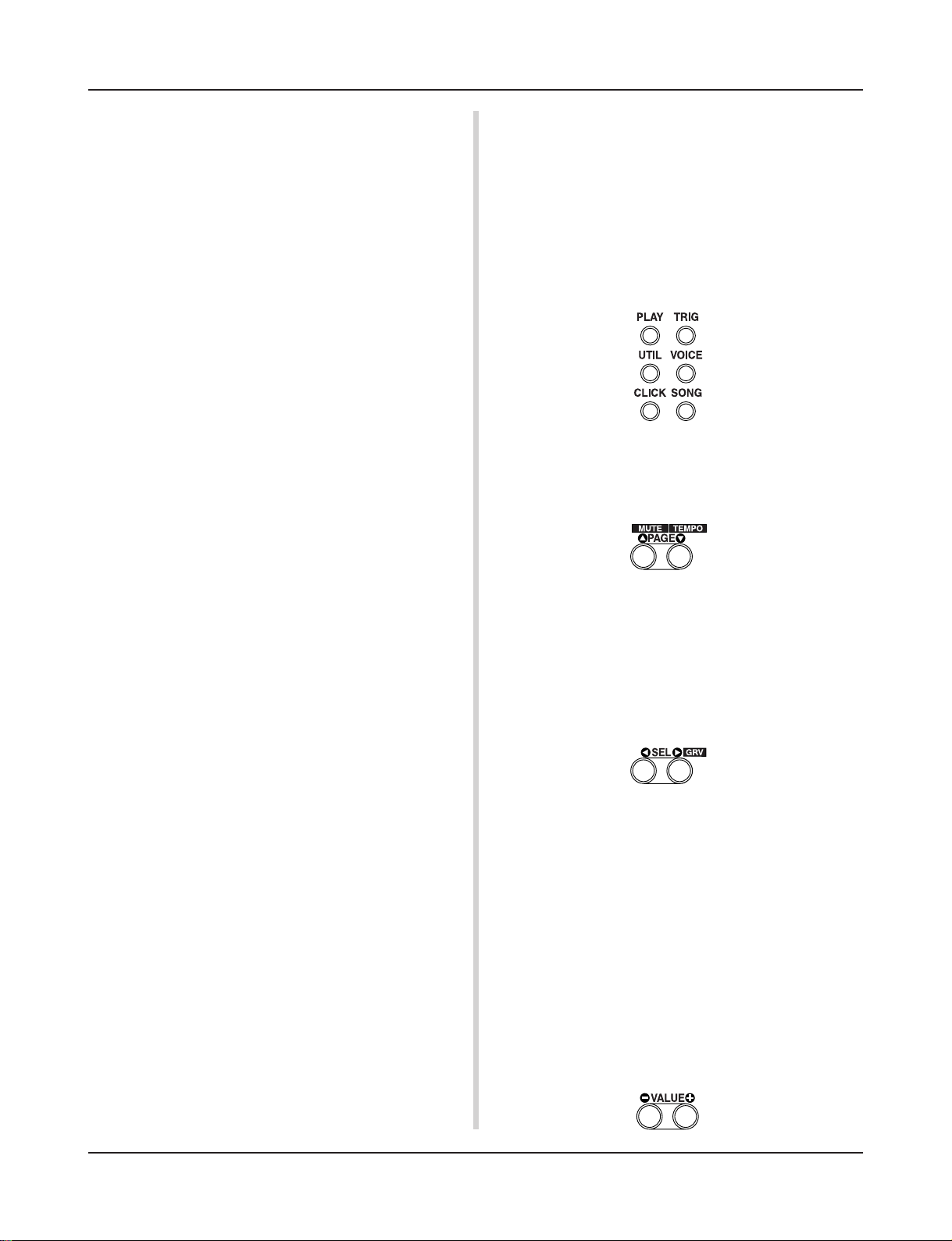
● Page Navigation
Press the [PAGEs] button to move to the previous page, the
[PAGEt] button to move to the next page. Hold the button to
scroll through the pages.
● Select the Parameter
The flashing parameter on the display is specified for setting.
• Use the [SEL<] and [SEL>] buttons to move the cursor (the
flashing character or symbol).
The [SEL<] button moves the cursor to the left while the
[SEL>] moves the cursor to the right.
•When there is only one parameter on the display, the [SEL<]/
[SEL>] buttons will not operate.
● Change the setting
The setting (value) of flashing parameter on the display can be
changed.
•The [VALUE–] and [VALUE+] buttons are used to set parameter values.
When setting values, press the [VALUE–] button to decrease
(minus) the value, press the [VALUE+] button to increase (plus)
the value. Holding the button will continue to decrease/increase
the value.
Hold the [VALUE–] and press the [VALUE+] button will decrease the value by 10. Continue to hold both buttons and the
value will continue to decrease.
Hold the [VALUE+] button and press the [VALUE–] button to
increase the value by 10. Continue to hold both buttons and the
value will continue to increase.
5
Drum Kit Play Mode
This mode enables you to play the DTXPRESS drum
voices by hitting the pads (or drums with trigger sensors attached) connected to the DTXPRESS.
The DTXPRESS automatically enters this mode when
the power is switched on.
You can select and play from 48 preset drum kits and 32
user kits.
Also, the drum kit, trigger setup and song specified in
this mode will be selected and ready for editing when
the Drum Kit Voice Edit, Trigger Setup Edit and Song
Job modes are entered.
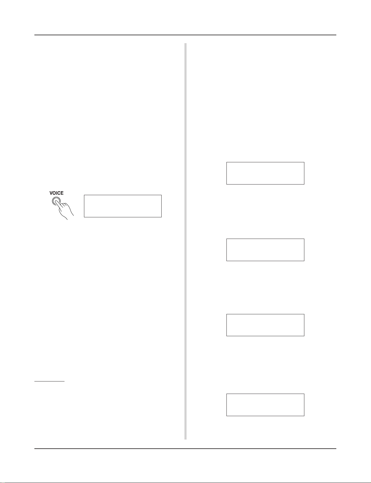
■ Entering the Drum Kit Play Mode
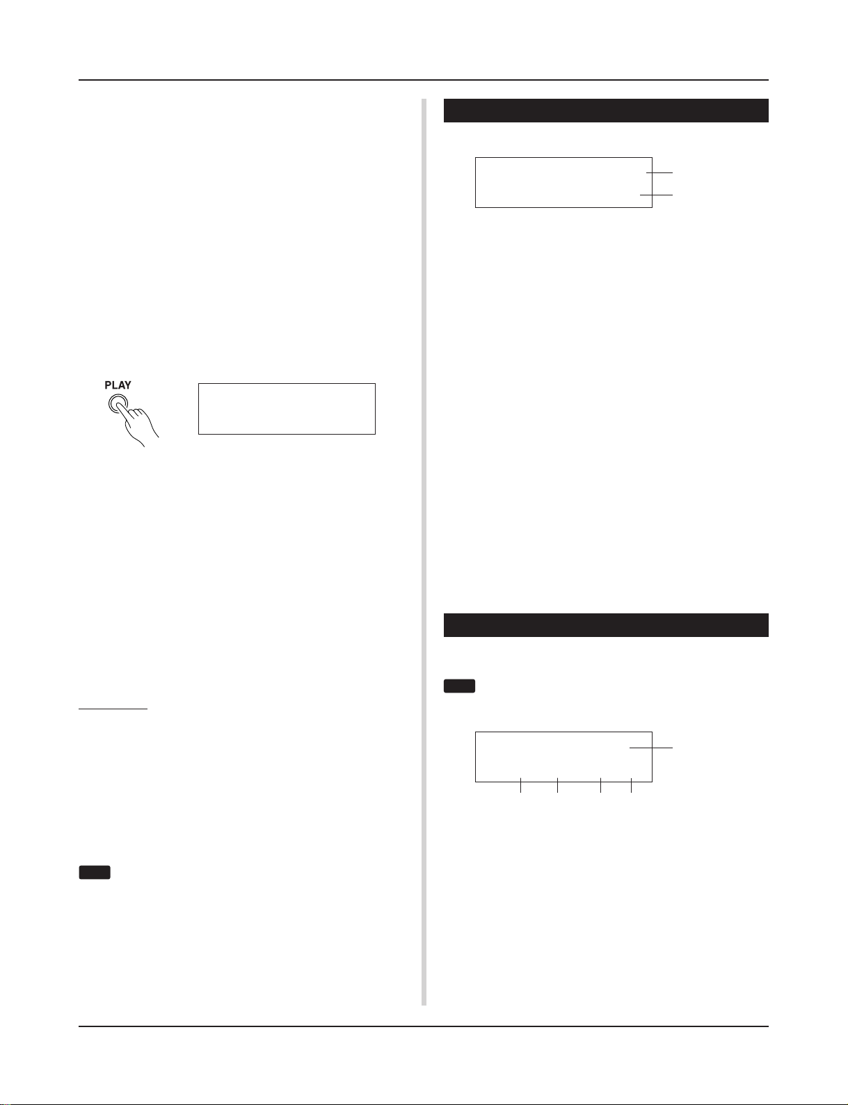
Press the [PLAY] button on the front panel.
Once the Drum Kit Play mode is entered, the Drum Kit & Song
display shown below will appear.
KIT =1 Acoustic
SONG=1
■ What’s in the Drum Kit Play Mode
The Drum Kit Play mode contains the three setting displays shown
below.
1. Drum Kit & Song .................................... (P. 6)
This display is used for selecting the drum kit and
song.
2. Trigger Setup & Tempo .......................... (P. 6)
This display is used for selecting the trigger setup
and song settings.
3. Song & Mute ........................................... (P. 7)
This display is used for selecting the song and
specifying the drum mute during the song.
Procedure
1.
Press the [PLAY] button to enter the drum kit play mode.
Latiniq
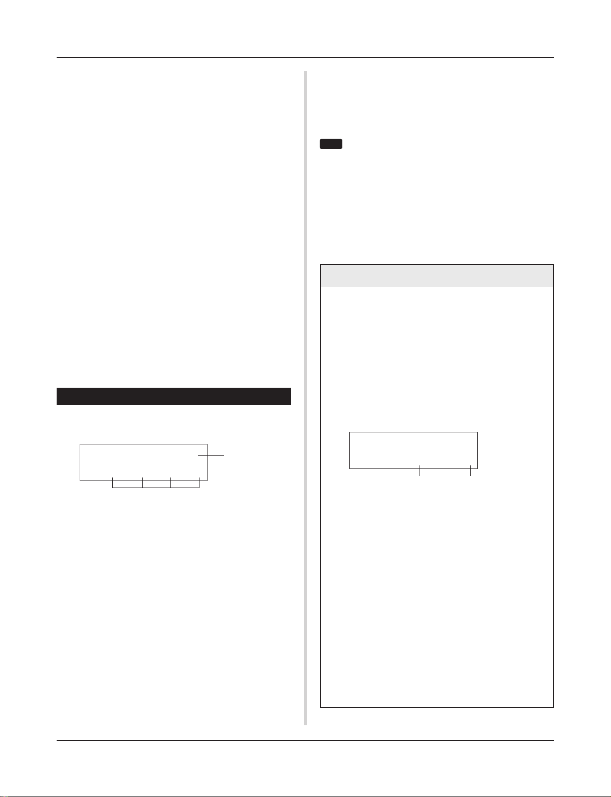
1. Drum Kit & Song
This display is used for selecting the drum kit and song.
KIT =1 Acoustic
SONG=1
q KIT (Drum Kit)
[Range] 1-80
Selects the drum kit. The drum kit number and drum kit name will
be displayed. Preset kits are numbered 1-48 and user kits are numbered 49-80.
When a pad is hit, the selected drum kit voice will be delivered.
Also, this drum kit will be specified for editing when the Drum
Kit Voice Edit mode is entered.
* Once a setting is changed in the Drum Kit Voice Edit mode, “*”
will appear between “KIT” and “=” until the data is stored.
* Refer to the [Preset Drum Kit List] (P. 42)
w SONG
[Range] 1-127
Selects the song. The song number and song name will be displayed. Preset songs are numbered 1-95 and user songs are numbered 96-127.
The selected song will playback when the [START/S] button is
pressed.
* When the rhythm mute ([SHIFT]+[PAGEs] is applied, the last
letter of the song name will be “˚”.
* Refer to [About the Song] (P. 8).
* Refer to the [Preset Song List] (P. 49).
Latiniq
q
w
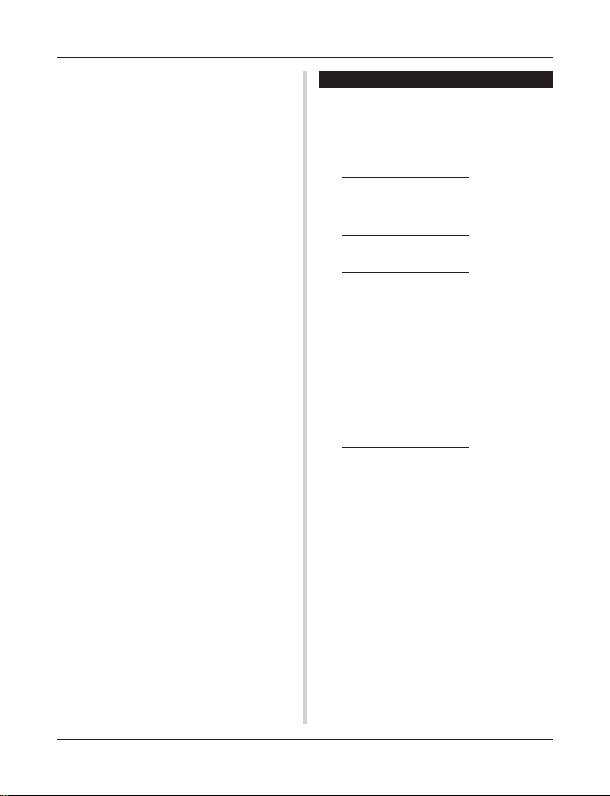
2. Trigger Setup & Tempo
This display is used for selecting the trigger setup and song settings.
Press the [SHIFT]+[PAGEt] buttons, in any Drum Kit
HINT
Play mode display, to jump to the following display with
the cursor moved to tempo value.
2.
Use the [PAGEs]/[PAGEt] buttons to select the page
you want to set.
3.
Use the [SEL<]/[SEL>] buttons to move the cursor to
the parameter you want to set. The parameter will flash.
4.
Use the [VALUE–]/[VALUE+] buttons to set the
parameter’s value.
Press the [SHIFT]+[PAGEt] buttons, in any Drum Kit
HINT
Play mode display, to jump to the Trigger Setup & Tempo
display with the cursor moved to tempo value.
6
TRIG =1 Medium
ƒ=110=--=
w
q TRIG (Trigger Setup)
[Range] 1-11
Selects the trigger setup to be used. The trigger number and trigger name will be displayed. Presets are numbered 1-7 and user
setups are numbered 8-11.
*For more information on the preset trigger setup, refer to the
[Trigger Setup List] (P. 49).
* Once a setting is changed in the Trigger Edit mode, “*” will ap-
pear between “TRIG” and “=” until the data is stored.
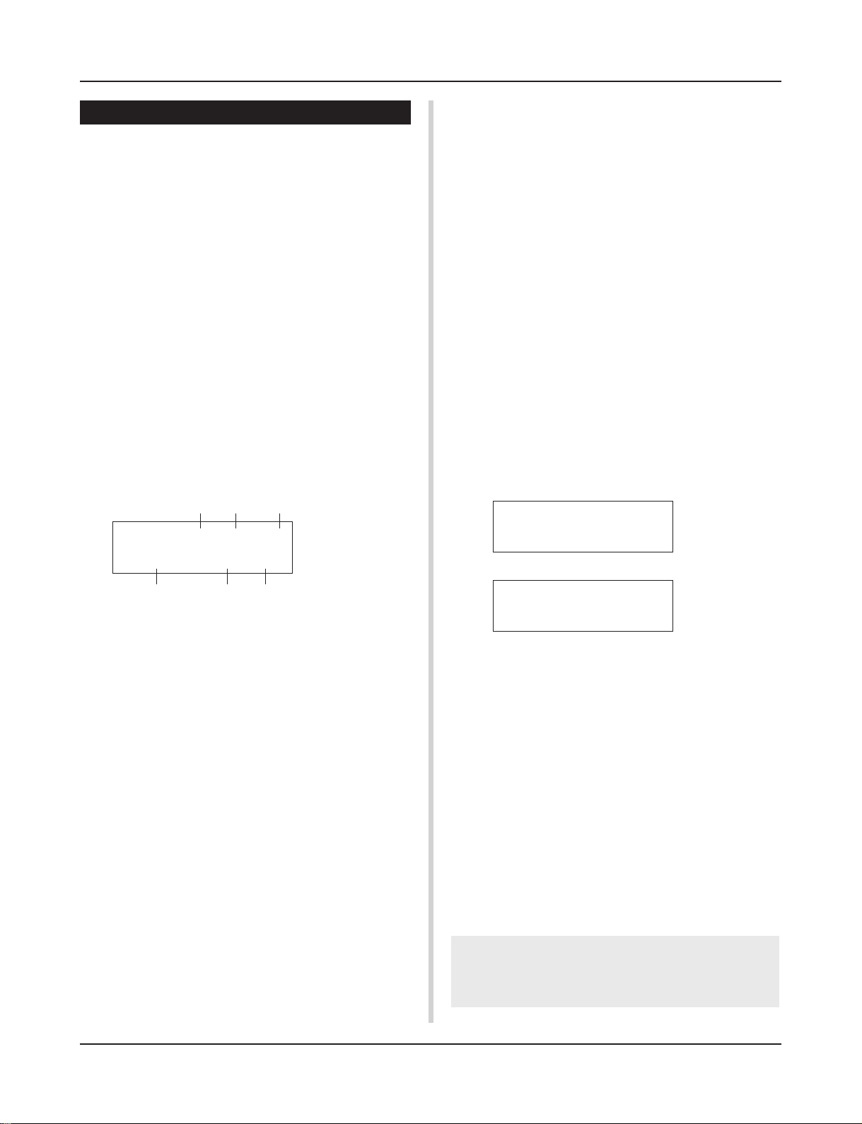
w q (Tempo)
[Range] 30-300, ext
Sets the playback tempo for the song.
4/4=ƒ
e r t
q
Drum Kit Play Mode
When the DTXPRESS is controlled by an external sync, “ext”
will be displayed.
* The external sync setting is found in [3-6. Sync Mode] (P. 33).
e Repeat Playback
[Range] —, rp
Sets the repeat playback (repeat continuously from the beginning
to the end of the song) of the song.
When this parameter is set to “rp”, the song will repeat playback.
When this parameter is set to “--”, the song will playback normally.
r Beat
[Range] 1/4-8/4, 1/8-16/8, 1/16-16/16
Sets the beat of the song (metronome).
t Metronome Note Value
[Range] When the beat r is set to 3/8, 6/8, 9/8, 12/8, 15/8, the
click tempo will be set to
ƒ quarter note, © eighth note, ˙ sixteenth note.
When the beat r is set to any value that is not listed
above, the click tempo will be set to
ƒ quarter note, ƒ3 quarter note (triplet),
© eighth note, ©3 eighth note (triplet),
˙ sixteenth note, ˙3 sixteenth note (triplet).
Use the note values to set the click tempo of the metronome.
3. Song & Mute
This display is used for selecting the song and specifying the drum
mute during the song.
SONG=1 Latiniq
q
Ki=®Sn=mCy=®Mi=®
w
q SONG
[Range] 1-127
Selects the song. The song number and song name will be displayed.
Press the [SONG] button to start playback of the selected song.
* This song select operation is the same as in [1. Drum Kit and
Song]. The only difference is whether the display will switch or
not when the Groove Check is used.
w Drum Mute
[Range] m (mute; Does not produce sound), ® (Produces sound)
Sets the type of drum voice to be muted. The 4 types of voices that
can be muted are Ki (kick), Sn (snare), Cy (cymbal) and Mi (others).
* Drum voice types
Drum voices are divided into many groups (categories) in accordance with the type of sound i.e. kick, snare, etc. For more
information on Drum Voice categories, refer to the [Drum Voice
List] (P. 38).
Drum Voice Category Mute Classification
K, k Ki (kick)
S, s Sn (snare)
C, H Cy (cymbal)
T, t, P, E, e, L, m Mi (others)
Since drum voices for pads (triggers) are not muted you
HINT
can, for example, mute the snare voice of a song and practice the snare part along with song playback (the snare
voice is delivered when the pad is hit).
Groove Check Function
Function
As you play the pads along with a song, the DTXPRESS will
compare your performance with its song clock and let you
know how accurate your timing is.
Display
In the Drum Kit Play mode (from any display) press the
[SHIFT]+[SEL>] (GRV) buttons.
* The Groove Check function will quit when song playback
is stopped.
* The top line of the original page is displayed as is.
KIT =1 Acoustic
Groov=
Setting
q Groov (Groove)
[Range] –48 to 0 to +48
The difference in the timing of each stroke on the pad is displayed.
If the timing of the stroke is late compared to the just time, a
minus value will be displayed. If your timing is early, a plus
value will be displayed. If you timing is perfect, “0” will be
displayed.
w Ave (Average)
[Range] –48 to 0 to +48
This function displays the average value of your timing accuracy after the Groove Check function is switched ON.
This function checks your performance on the entire drum
set and can check your performance on one song. The information shown in the display is the same as in q Groov.
*To reset the data, press the [SHIFT]+[SEL>] buttons twice.
0Ave= 0
q
w
7
About the Song
The DTXPRESS can internally store data for a maximum of 127
songs that can be played back freely.
Song numbers 1-95 are preset songs and song data in those songs
cannot be changed or rewritten.
Song numbers 96-127 are user songs that can be used to record
new performance data and also edit song data in.
■ Song Makeup
The Song consists of two sequencer tracks plus header data.
Header data is written at the front of the song and holds information related to the song’s tempo, beat, program numbers (voice)
for each MIDI channel and volume, etc. Header data is read every
time the song is played from the beginning.
Both tracks possess data for MIDI channels 1-16 (except system
exclusive data).
Durring song playback, the sequencer data that is written in the
song will be transmitted to the DTXPRESS’ tone generator to produce the song.
■ Main Song and Pad Song
Up to four songs can be played back simultaneously.
The song that is selected in the Drum Kit Play mode (P. 6) is called
the Main Song. Pressing the [START/S] button will start playback
of this song.
The remaining three songs are called Pad Song(s). These songs
are played back according to the trigger input (hitting a pad).
■ Metronome
The sequencer produces the metronome.
The metronome can be used either alone or with the Song.
Press the [CLICK] button, in any mode, to start the metronome.
The metronome’s tempo, voice, etc. are set in the Utility mode [3.
Sequencer Group] (P. 32).
Song Playback
■ Main Song Playback
• Select a Song
1.
Press the [PLAY] button to enter the Drum Kit Play mode.
Use the [PAGEs]/[PAGEt] buttons to display either of
the displays shown below (Drum Kit & Song or Song &
Mute).
• Drum Kit & Song
KIT =1 Acoustic
SONG=1
• Song & Mute
Latiniq
SONG=1 Latiniq
Ki=®Sn=®Cy=®Mi=®
2.
Use the [SEL<]/[SEL>] buttons to move the cursor to
the “SONG=” position.
3.
Use the [VALUE–]/[VALUE+] buttons to set the song num-
ber of the song you want to playback.
• Set the Tempo, Repeat Playback, Beat and Metronome
1.
In the Drum Kit Play mode, use the [PAGEs]/[PAGEt]
buttons to display the “Trigger Setup & Tempo” display
shown below.
TRIG =1 Medium
ƒ=120=--=
2.
Use the display shown above to set the Tempo, Repeat
Playback, Beat and Metronome Note Value.
4/4=ƒ
• Song Playback (Start/Stop)
Press the [START/S] button, in any display, to start playback of
the song (main song).
During playback, press the [START/S] button to stop playback of
the song. Press the [START/S] button again and the song will start
playback from the beginning.
* If the pad’s function is previously set to the “Main Song Control”
function (m Drum Kit Voice Edit Mode [2-6. Function] P. 20), you
can start/stop the main song by hitting the assigned pad.
* During song playback, the [SONG] button’s LED will light for a
moment at the beginning of each measure.
* During song playback, the song cannot be changed.
* If the song’s tempo or voices are irregular, re-select the song.
8

About the Song
■ Pad Song Playback (Start/Stop)
To playback a Pad Song, hit the pad that is assigned to the Pad
Song you want to playback. Hit the same pad during playback will
stop the song. Hit the pad again to start the song from the beginning.
* Before using, set the pad’s function to “Pad Song Control” and
assign a song to the pad (m Drum Kit Voice Edit mode [2-6.
Function], [2-7. Pad Song] P. 20).
* The song can be played one measure at a time, each measure
triggered with a stroke on the pad (m Drum Kit Voice Edit mode
[2-7. Pad Song] P. 20)
* If the Pad Song’s tempo or voices are irregular, re-select the
Drum Kit.
■ Song Playback Functions
During song playback, the song can be repeated and volume levels for each instrument can be changed.
• Volume Control
With each of the knobs on the front panel, the following volume
levels can be controlled.
• [ACCOMP VOL]: The volume of the song’s accompaniment.
• [SHIFT]+[ACCOMP VOL]: The volume of the song’s snare
drum.
• [CLICK VOL]: The volume of the metronome’s click.
• [SHIFT]+[CLICK VOL]: the volume of the song’s bass drum.
If the Utility mode’s [1-3. Volume Mode] (P. 28) is set to “live”,
the following volume levels can be controlled.
• [ACCOMP VOL]: The volume of the song’s snare drum.
• [SHIFT]+[ACCOMP VOL]: The volume of the song’s cymbal.
• [CLICK VOL]: The volume of the song’s bass drum.
• [SHIFT]+[CLICK VOL]: The volume of the song’s other instruments.
• Rhythm Mute Function
When the [SHIFT]+[PAGEs] buttons are pressed, the MIDI channels (usually channel 10) that are assigned to track 1 of the song
and the drum voice will be muted (sound will not be delivered).
* When the Rhythm Mute is applied, program changes will be ig-
nored so the drum kit cannot be changed.
• Other Functions
• This function can set whether the song will playback according to the tempo information in the song or according to the
tempo that is set when the song is switched. (m P. 34 [3-7.
Use Tempo])
• This function can set whether or not the click voice will be
delivered automatically when the song is played back. (m P.
34 [3-8. Click Mode])
•The metronome’s click voice can be switched ON/OFF by hitting the pad. (m P. 20 [2-6. Function])
• Set the Metronome
The voice, pitch and MIDI note number of the metronome’s click
voice can be set. ([3-1. Click Voice] (P. 32), [3-2. Click Tune] (P.
33), [3-3. Click Note Number] (P. 33)
• Count Function
If the Utility mode’s [3-5. Count Switch] (P. 33) is set to “on”
when the main song is played back, the first measure of the song
will be preceded by a two measure count.
• MIDI Control by an External Device
• If the Utility mode’s [3-4. MIDI Control] (P. 33) is set to “on”,
playback of the main song can be controlled with system realtime messages (start/continue/stop) from the MIDI IN/TO
HOST jack.
• If the Utility mode’s [3-6. Sync Mode] (P. 33) is set to “ext”
or “auto”, the song playback can be synchronized to the clock
of an external MIDI device.
9
About the Song
Song Recording
Song recording lets you record data, produced as the drum kit is
played, to the sequencer in real-time (one track at a time). All MIDI
channels (1-16) are recorded simultaneously. Also, data produced
by a MIDI keyboard connected to the MIDI IN jack can be recorded as well as sequencer data received via the MIDI IN/TO
HOST jacks.
According to the recorded sequencer data (performance information), drum kits and voices can be changed during song playback.
The songs that are recorded can be played back and edited in the
same manner as preset songs (No. 1-48) with the Song Job mode.
■ Song Record Settings
• Select the Song
1.
Press the [PLAY] button to enter the Drum Kit Play mode,
set the User Song number (No. 96-127) that you want to
record to.
* Only User Songs (No. 96-127) can be used for recording.
Preset Songs (No. 1-95) cannot be used for recording.
• Set the Recording Conditions (Record Standby)
2.
Press the [SHIFT]+[START/S] buttons, the record mode
will be in standby. The following display will appear.
q w e
REC M= 32=Rp1†=1
ƒ=120
3.
Use the display shown above to set the following recording conditions.
q M (the number of measures that will be recorded)
[Range] 1-999
Assigns the number of measures that will be recorded. When
there is data in the other track, the number of measures in that
track will decide the length of the song and this length cannot
be changed.
w Record Mode
Select the method of recording from the following.
Overwrite (Ovr): The record operation will be in a repeat
mode. When the song reaches the end of the last measure, it
will automatically start again from the beginning and new
data will be added to the track’s previous data.
Replace (Rpl): When the song reaches the end of the mea-
sure number assigned in “M” or the [START/S] button is
pressed, recording will stop (the song will not repeat).
e TR (Specify the Track for Recording)
Selects which track (“1” or “2”) will be recorded.
r q (Metronome Tempo) [Range] 30-300
Sets the metronome tempo for recording
t B (Beat) [Range] 1/4-8/4, 1/8-16/8, 1/16-16/16
Sets the beat of the song (metronome) for recording.
B= 4/4Q=©
r y
t
y Q (Quantize Accuracy)
[Range] ƒ quarter note, ƒ3 quarter note (triplet)
© eighth note, ©3 eighth note (triplet)
˙ sixteenth note, ˙3 sixteenth note (triplet), no
The Quantize function* can be used when recording.
When set to “no”, the Quantize function will not operate.
Quantize: This function is used to correct the timing of recorded
MIDI note data. The accuracy of quantization is assigned
by the note value.
*You can also use the Quantize function after recording is com-
plete. (Song Job mode [5. Quantize] P. 25)
• Record
4.
Press the [START/S] button to start recording.
* If the Utility mode’s [3-4. MIDI Control] (P. 33) is set to “on”,
the recording operation can be started with a system real
time message (start) received via the MIDI IN/TO HOST jacks.
* When the track assigned for recording contains data and the
[START/S] button is pressed, the error message “Data
Empty” will appear and the recording operation will not be
carried out.
While the song is recording, the following display will appear
(only displayed, cannot change).
• When the Record Mode = Replace (“Rpl”)
REC M= 5=Rp†=1
Now Recording.
• When the Record Mode = Overwrite (“Ovr”)
REC M= 5=Ovr†=1
UNDO press ENT
•Next to “M=” the measure number currently being recorded is
displayed.
• When the Record mode is set to “Ovr”, press the [SAVE/
ENT] button to “Undo” (do again) the record operation. Press
the [SAVE/ENT] button while recording to start recording from
the top of the song. The data previously recorded from the
beginning of the song, up until the [SAVE/ENT] button was
pressed, will revert to the data originally present.
• Stop Recording
5.
When the song reaches the end of the assigned measure number, recording will automatically stop and the
DTXPRESS will return to the Drum Kit Play mode (Drum
Kit & Song display).
* Recording can also be stopped anytime by pressing the
[START/S] button.
* If the power is switched off while recording, all the data in the
User Song may be lost. Please use caution.
Data recorded in the tracks cannot be overwritten. To
record new data, use the Song Job mode’s [6. Clear Track]
(P. 26) or [8. Clear Song] (P. 26) operations to erase track
data.
not
10
Trigger Setup Edit Mode
This mode contains various settings related to trigger
input from the pads and trigger sensors that are connected to the DTXPRESS.
It allows you to adjust pad sensitivity and assign drum
voices to each trigger input. Trigger Setup data consists
of seven preset types (No. 1-7) and four original setup
types (No. 8-11) for storing user setup data.
■ What you can do with the Trigger Setup Edit
Mode
The Trigger Setup Edit Mode lets you alter a variety of settings for
each of the trigger inputs jacks (1-10) of the Trigger Setup.
You can edit both preset (No. 1-7) and user Trigger Setups (No. 8-
11).
The edited Trigger Setup can be stored in a User Trigger Setup
(No. 8-11) using the Store Operation.
* Selecting another Trigger Setup before storing your changes
will result in the data reverting to its default settings.
* Data cannot be stored to preset Trigger Setup (No. 1- 7).
■ Entering the Trigger Setup Edit Mode
Press the [TRIG] button on the front panel.
Once the Trigger Setup Edit Mode is entered, the INPUT
parameter’s main page (pad type), shown below, will be displayed.
TRIG IN= 1
Type=
KP
5.
Use the [VALUE–], [VALUE+] buttons to set the
parameter’s value or ON/OFF setting.
* Once a setting is changed, “*” will appear on the display next
to “TRIG”. After data is saved, the mark will disappear.
TRIG*IN= 1
Type=
6.
To store changes in the User Trigger Setup, use the following procedure.
* The changes you made will be lost if another trigger setup is
selected before your changes have been stored.
6-1. Press the [SAVE/ENT] button. The following display will
appear.
KP
Store Trigger
8 InitTrig
To=
6-2. Use the [VALUE–], [VALUE+] buttons to assign the User
Trigger Setup number (8-11) (located next to “To=”) for
storing your changes. The number and setup name will
appear.
6-3. Press the [SAVE/ENT] button, the following display will
appear asking for confirmation before the store operation is carried out.
Store TRG to 8
Are you sure ?
* Double-click the [TRIG] button to enter the Trigger Setup Edit
Mode. The [1-2. Gain, Minimum Velocity] display will appear.
■ What’s in the Trigger Setup Edit Mode
The Trigger Setup Edit Mode is divided into two sub-groups.
1. INPUT Parameters ............................... mP. 1 2
Contains specific settings for each pad (1-10).
2. COMMON Parameters ......................... mP. 1 4
Contains common settings for all pad inputs.
Procedure
1.
Before editing, it is necessary to select the trigger setup
you want to edit in the drum kit play mode [Trigger Setup
& Tempo].
2.
Press the [TRIG] button to enter the Trigger Setup Edit
mode.
3.
Use the [PAGE▲], [PAGE▼] buttons to display the list
you want to edit.
* If the Utility mode’s [Jump to Recent Page] parameter (P. 28)
is set to “on”, the DTXPRESS will display the page last edited when entering the Trigger Setup Edit mode.
4.
Use the [SEL<], [SEL>] buttons to move the cursor to
the list you want to edit. The list will flash.
* If there is only one list, it is not necessary to move the cursor.
6-4. Press the [SAVE/ENT] or [VALUE+] button, the store
operation will be carried out.
*Press the [VALUE–] button to cancel the store opera-
tion.
The following display will appear after the store operation is completed.
Complete !
Trigger Setup Edit Mode Function List
Page
1. INPUT Parameters .................................................. 12
1-1. Pad Type .......................................................... 12
1-2. Gain, Minimum Velocity ................................... 12
1-3. Velocity Curve ................................................. 13
1-4. Self Rejection, Rejection ................................. 13
1-5. Specific Rejection ............................................ 13
1-6. Copy Input ....................................................... 13
2. COMMON Parameters ............................................ 14
2-1. Increment/Decrement ...................................... 14
2-2. Input Exchange ............................................... 14
2-3. Trigger Setup Name ........................................ 14
11
Trigger Setup Edit Mode
1. INPUT Parameters
Contains specific settings for each of the pads (1-10).
This function is divided into the following 6 pages.
1-1. Pad Type .......................................................... 12
1-2. Gain, Minimum Velocity ................................... 12
1-3. Velocity Curve ................................................. 13
1-4. Self Rejection, Rejection ................................. 13
1-5. Specific Rejection ............................................ 13
1-6. Trigger Setup Copy.......................................... 13
1-1. Pad Type
Sets the type of pad or trigger sensor that is connected to the trigger input jack q. By selecting the appropriate pad type, pad functions can be used to their full potential.
2 Extensive use 2—high sensitivity type.
misc
Rim switch function is good for cymbal use.
3 Extensive use 3—normal sensitivity type.
misc
Rim switch is good for snare/tom use.
misc
4 Extensive use 4—normal sensitivity type.
Rim switch function is good for cymbal use.
misc 5 Extensive use 5—low sensitivity type.
Rim switch is good for snare/tom use.
6 Extensive use 6—low sensitivity type.
misc
Rim switch function is good for cymbal use.
HH contrler
* The DT10, DT20 are Yamaha Drum Trigger Sensors.
Connect the HH60, HH80, HH80A to Trigger In-
put jack 1 to use as a kick pedal.
* The volume (velocity) is fixed.
1-2. Gain, Minimum Velocity
TRIG IN= 1
Type=
q TRIG IN (Trigger Input Number)
[Range] 1-10
Assigns the trigger input jack number for the pad you want to edit.
* According to the setting in the utility mode’s [1-1. Learn Mode]
(P. 28) trigger input jack numbers can be assigned by hitting the
pad.
w Type (Pad Type)
Sets the type of pad that is connected to the trigger input jack
assigned in q TRIG IN.
*Values set in [1-2. Gain, Minimum Velocity] (P. 12) and [1-4. Self
Rejection] (P. 13) will automatically select the proper value for
the pad type you set here.
* The “HH
nect the Hi-hat Controller HH60, HH80 or HH80A to Input Jack
1 and set to “HH
Use a cable with a stereo plug when connecting a Hi-hat controller.
Pad types are defined as follows.
TP
snare TP60, TP80, TP80S used as a snare pad.
tom TP60, TP80, TP80S used as tom pads.
TP
HH TP60, TP80, TP80S used as a hi-hat pad.
TP
KP KP60, KP80, KP80A used.
ride PCY60, PCY80, PCY80S used as ride cymbal
PCY
PCY
crash PCY60, PCY80, PCY80S used as crash cymbal
PCY
cup PCY10, etc. used as the cymbal cup.
BP BP80 used.
snare DT10, DT20 attach to the snare drum.
DT
hi tom DT10, DT20 attach to small toms
DT
lo tom DT10, DT20 attach to large toms
DT
kick 1 DT10, DT20 attach to small bass drum
DT
DT
kick 2 DT10, DT20 attach to large bass drum
misc 1 Extensive use1—high sensitivity type.
KP
contrler” can only be assigned to Input Jack 1. Con-
contrler” to use in place of a kick pedal.
pads.
pads.
Rim switch function is good for snare/tom use.
q
w
This function sets the input sensitivity (Gain) and velocity range
(Minimum Velocity) for each input jack q.
q
TRIG IN= 1 ( 0%)
Gain=64
q TRIG IN (Trigger Input Number)
Assigns the trigger input jack number. (The same procedure as in
[1-1. Pad Type]).
w GAIN (Input Gain)
[Range] 0-99
Adjusts the input gain level (minimum sensitivity) for the trigger
input jack assigned in step q TRIG IN.
Entering a larger value here allows smaller input levels to sound
the voice.
* This value will be automatically set after the appropriate pad
type is set in [1-1. Pad Type]. Some fine-tuning of the value will
be necessary.
e MVel (Minimum Velocity)
[Range] 1-127
Sets the MIDI Velocity (volume) that is transmitted when the pad
is hit the weakest. Large values will produce a high volume level
even if the pad is hit softly. However, this will result in a narrow
volume range making it difficult to adequately produce wider dynamic levels.
HH contrler
If “
be transmitted as the velocity.
The trigger input level will be displayed as a % in the upper right
hand corner of the display. The maximum velocity (input level
99%) will be 127. The level is low when the pad is hit the weakest
so a wider dynamic range will be possible.
* This value will be automatically set after the appropriate pad
type is set in [1-1. Pad Type]. Some fine-tuning of the value will
be necessary.
MVel= 32
w
” is set for the pad type, the value set here will
Level Display
e
12
Trigger Setup Edit Mode
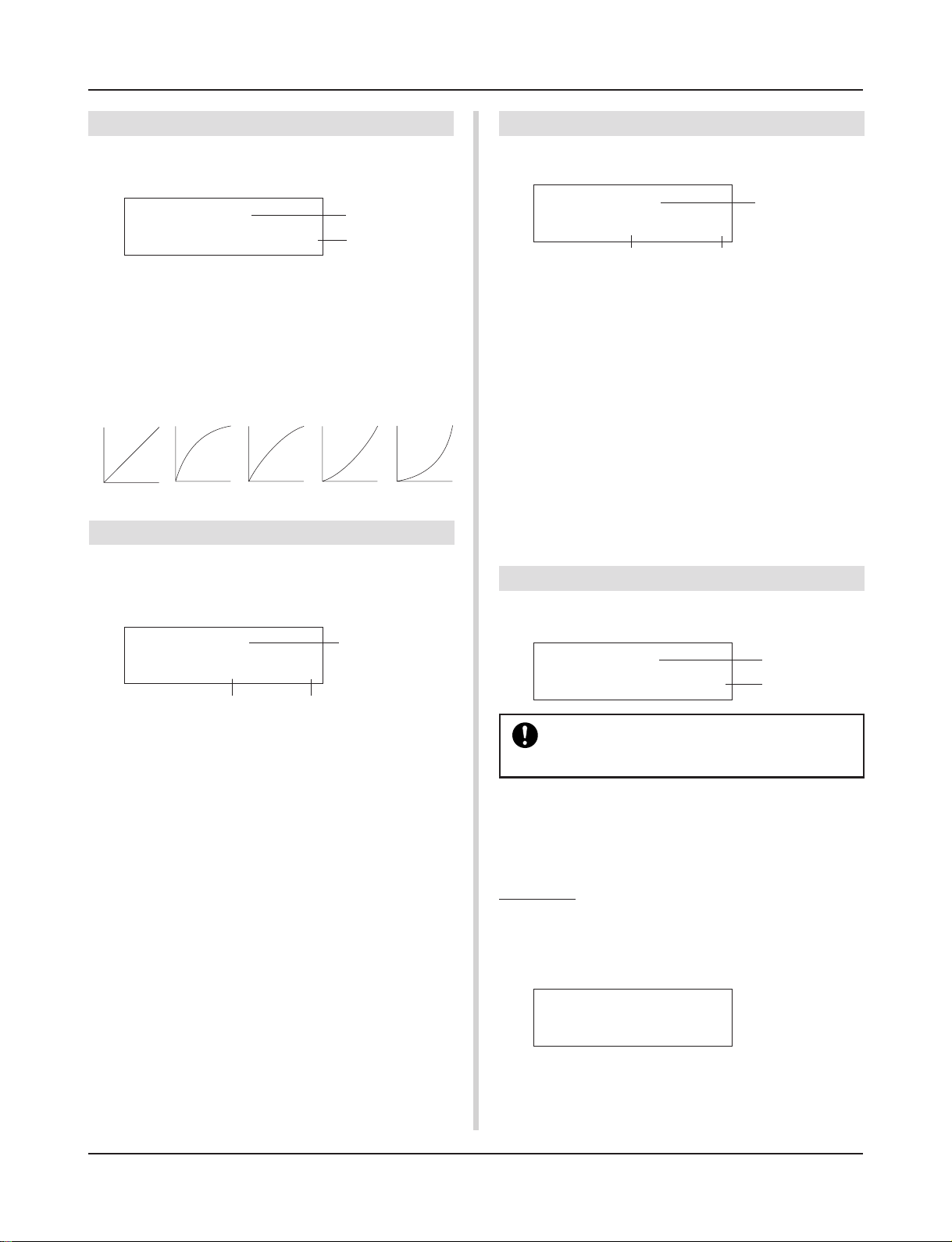
1-3. Velocity Curve
This function sets the MIDI Velocity Curve for the sensitivity for
each input jack q.
hard
q
w
1
hard
2
TRIG IN= 1
VelCurve=
q TRIG IN (Trigger Input Number)
Assigns the trigger input jack number (the same procedure as in
[1-1. Pad Type]).
w VelCurve (Velocity Curve)
Sets the Input Velocity Curve for the trigger input jack assigned in
TRIG IN q.
normal
m
Velocity
Strength
of hitm
normal
2
loud1loud
1-4. Self Rejection, Rejection
This function is used to prevent double triggers* and cross talk
(mixed input signals between the jacks) for each input jack q.
* double trigger: When 2 sounds are played at the same time.
TRIG IN= 1
SelfRej=2
q TRIG IN (Trigger Input Number)
Assigns the trigger input jack number (the same procedure as in
[1-1. Pad Type]).
w SelfRej (Self Rejection)
[Range] 0-9
Prevents double triggers from occuring in the input jack assigned
in TRIG IN q. After an event is detected, further events will be
automatically muted for a certain length of time. Larger values set
longer times.
e Rej (Rejection)
[Range] 0-9
Prevents cross talk from occuring in the input jack assigned in
TRIG IN q. Events triggered by other pads (input jacks) that are
of a lower input value than what is set here will not be delivered
for a set length of time.
Rej= 3
w e
q
1-5. Specific Rejection
This function prevents cross talk from occurring between two specified input jacks q and e.
TRIG IN= 1
SPCRej=0
q TRIG IN (Trigger Input Number)
Assigns the trigger input jack number (the same procedure as in
[1-1. Pad Type]).
w SPCRej (Specific Rejection)
[Range] 0-9
After an event occurs from the pad from the input jack assigned in
e, the pad of the input jack assigned in TRIG IN q will not
sound for a certain length of time unless the level is greater than
the value assigned here.
e frm (Assigned Destination Trigger Input Number)
[Range] 1-10, 6&7
Sets the destination trigger input jack number of the pad that will
be rejected. When “6&7” is selected, both trigger inputs 6 and 7
will be assigned.
frm= 1
w
q
e
1-6. Trigger Setup Copy
This function copies all data settings in [1-1. Pad Type] to [1-5.
Specific Rejection] from input jack q to another input jack w.
TRIG IN= 1
Copy
to Input= 1
When the Trigger Setup Copy operation is carried
out, the trigger setup data will be replaced with the
settings of the copy source.
q TRIG IN (Trigger Input Number)
Sets the trigger input jack number (1-10) of the pad copy source.
w Copy to Input (
Sets the trigger input jack number (1-10) of the copy destination.
Trigger Input Number Copy Destination
q
w
Procedure
1.
In the display shown above, assign the copy source and
copy destination, press the [SAVE/ENT] button. The following display will appear asking for confirmation before
the copy operation is carried out.
Input Copy to 1
Are you sure ?
)
2.
Press the [SAVE/ENT] or [VALUE+] button, the copy
operation will be carried out.
* Press the [VALUE-] button to cancel the copy operation.
When the copy operation is complete, “Complete!” will appear.
13
Trigger Setup Edit Mode
2. COMMON Parameters
Contains common settings for all pad inputs (1-10).
This group is divided into the following 3 pages.
2-1. Increment/Decrement ...................................... 14
2-2. Input Exchange ............................................... 14
2-3. Trigger Setup Name ........................................ 14
2-1. Increment/Decrement
This sets the pad function that allows the currently selected drum
kit number to be increased or decreased by 1 by hitting the specified pad.
TRIG Common
IncIn=
q Incin (Pad for Increment)
[Range] —, 1-10
Assigns the trigger input jack number that is set for the increment
(+1) function. “--” will appear when this function is not assigned
to the pad.
w Decin (Pad for Decrement)
[Range] —, 1-10
Assigns the trigger input jack number that is set for the decrement
(-1) function. “--” will appear when this function is not assigned
to the pad.
*Even when the drum kit is changed, the pads connected to the
assigned trigger input jacks will retain their increment/decrement functions. To assign this function to each drum kit, refer to
the Drum Kit Voice Edit mode’s [2-6. Function] (P. 20)
4DecIn= 5
q
2-2. Input Exchange
w
When the input jack 9 pad is hit.
m This event will be recognized as a signal from the input jack
1 pad (as if a trigger were received from input jack 1) and
operate accordingly.
When the input jack 10 pad is hit.
m This event will be recognized as a signal from the input jack
9 pad (as if a trigger were received from input jack 9) and
operate accordingly.
2-3. Trigger Setup Name
Changes the name of the currently selected (currently being edited) Trigger Setup.
TRIG Common
TrgName=Medium
q TrgName (Trigger Setup Name)
Procedure
1.
In the display shown above, use the [SEL<]/[SEL>] buttons to move the cursor to the character you want to
change.
2.
Use the [VALUE–]/[VALUE+] buttons to select the alphabet, number or symbol.
3.
Repeat steps 1 and 2 above to create the Trigger Setup
name using a maximum of 8 characters.
● The available characters to choose from are (in order):
space
!"#$%&'()*+,-./0123456789:;<=>?@
ABCDEFGHIJKLMNOPQRSTUVWXYZ[\]^_`
abcdefghijklmnopqrstuvwxyz{|}ßå
q
Switches the trigger signal from the pads between trigger input
jacks 1 and 9/10.
TRIG Common
Excg= normal
In
q In Excg (Input Exchange)
normal: Normal operation.
In10,1/9: The signals from Input Jacks 1 and 9/10 are switched.
When the input jack 1 pad is hit.
m This event will be recognized as a signal from the input jack
10 pad (as if a trigger were received from input jack 10) and
operate accordingly.
When the input jack 1 rim is hit.
m Normal operation. This event will be recognized as a signal
from the input jack 1 rim.
14
q
Drum Kit Voice Edit Mode
This mode lets you set which voice and how it will be
triggered for each pad (trigger input source) in the currently selected drum kit.
■ What you can do with the Drum Kit Voice
Edit Mode
This mode contains various settings related to the currently selected drum kit (data in the edit buffer for the drum kit).
You can edit both preset (No. 1-48) and user drum kits (No. 49-
80).
The edited drum kit can be stored in a User Drum Kit (No. 49-80)
using the Store Operation.
* Selecting another drum kit before storing your changes will re-
sult in the data reverting to its default settings.
* Data cannot be stored to preset drum kits (No. 1- 48).
■ Entering the Drum Kit Voice Edit Mode
Press the [VOICE] button on the front panel.
Once the Drum Kit Voice Edit Mode is entered, the Voice Parameter main page (Voice) shown below will be displayed.
KIT IN=pad 1 V=1
=K/017
* Double-click the [VOICE] button to enter the Drum Kit Voice Edit
Mode. The [1-2. Volume, Pan] display will appear.
■ What’s in the Drum Kit Voice Edit Mode
The Drum Kit Voice edit Mode is divided into the following five
sub-groups.
1.Voice Parameters .............................. (m P. 16)
Sets the voice for each input source of the pad.
2. Input Common Parameters ............. (m P. 19)
Common settings related to the 2 layers for each
pad input source’s voice parameter.
3. Reverb Parameters .......................... (m P. 21)
Sets the internal reverb effect.
4. Setup ................................................. (m P. 22)
When the drum kit is selected, this function copies the drum kit voice settings and MIDI transmit
settings.
5. Drum Kit Common Parameters ...... (m P. 23)
Common settings for the entire drum kit.
BDaftty1
3.
Use the [PAGEs], [PAGEt] buttons to display the page
you want to edit.
* If the Utility Mode’s [1- 4. Jump to Recent Page] (P. 28) pa-
rameter is set to “on”, the DTXPRESS will display the page
last edited when entering the Drum Kit Voice Edit Mode.
4.
Use the [SEL<]/[SEL>] buttons to move the cursor to
the parameter you want to edit. The parameter will flash.
* If there is only one parameter, it is not necessary to move the
cursor.
5.
Use the [VALUE–]/[VALUE+] buttons to set the
parameter’s value or ON/OFF setting. Pressing the
[VOICE] button lets you listen to the Drum Kit Voice while
editing.
* Once a setting is changed, “*” will appear on the display next
to “KIT”. After data is stored, the mark will disappear.
KIT*IN=pad 1 V=1
=K/019
6.
To store your changes in a User Drum Kit, use the Store
Operation described below.
* The changes you made will be lost if another drum kit is se-
lected before your changes have been stored.
6-1. Press the [SAVE/ENT] button. The following display will
appear.
MapleA20
Store Drumkit
To=
49 Init Kit
6-2. Use the [VALUE-]/[VALUE+] buttons to assign the Drum
Kit number (49-80) (located next to “To=”). The number and drum kit name will appear.
6-3. Press the [SAVE/ENT] button, the following display will
appear asking for confirmation before the store operation is carried out.
Store KIT to= 49
Are you sure ?
6-4. Press the [SAVE/ENT] or [VALUE+] button, the store
operation will be carried out.
*Press the [VALUE-] button to cancel the store opera-
tion.
Procedure
1.
Before editing, it is necessary to select the drum kit you
want to edit in the Drum Kit Play Mode of the [Drum Kit &
Song] display.
2.
Press the [VOICE] button to enter the Drum Kit Voice
Edit Mode.
The following display will appear after the store operation is complete.
Complete !
15
Drum Kit Voice Edit Mode
Drum Kit Voice Edit Mode Function List
Page
1. Voice Parameters.................................................... 16
1-1. Voice................................................................ 17
1-2. Volume, Pan .................................................... 17
1-3. Tuning .............................................................. 17
1-4. Layer Balance.................................................. 18
1-5. Decay, Cutoff Frequency ................................. 18
1-6. Note Number ................................................... 18
1-7. Channel, Gate Time ........................................ 18
2. Input Common Parameters .................................... 19
2-1. Cross Fade ...................................................... 19
2-2. Reverb Send.................................................... 19
2-3. Alternate Group, Key Assign Mode ................. 19
2-4. Hold Mode ....................................................... 20
2-5. Key Off Enable ................................................ 20
2-6. Function........................................................... 20
2-7. Pad Song......................................................... 20
2-8. Rim to Pad....................................................... 21
3. Reverb Parameters ................................................. 21
3-1. Reverb Type, Time ........................................... 21
3-2. Reverb Master Return ..................................... 21
4. Setup ....................................................................... 22
4-1. Program Change, Bank Select ........................ 22
4-2. Volume, Pan .................................................... 22
4-3. Drum Kit Voice Copy ....................................... 22
5. Drum Kit Common Parameters ............................. 23
5-1. Volume ............................................................ 23
5-2. Drum Reverb Send.......................................... 23
5-3. Hi-Hat Sensitivity ............................................. 23
5-4. Song Select ..................................................... 23
5-5. Drum Kit Name ................................................ 23
1. Voice Parameters
Sets the voice for each input source of the pad.
The Input Source is trigger data that is transmitted by the pads or
trigger sensors connected to input jacks 1-10 of the DTXPRESS.
When monaural pads TP60/80, KP60/80, PCY60/80, DT10/20,
etc. are used, one Input Source will be assigned to one input jack.
When stereo pads TP80S, PCY80S, etc. are used, two Input Sources
(pad input and rim switch input or 2 kinds of pad input, etc.) will
be assigned to one input jack.
The Voice Parameter is divided into the following 7 pages.
1-1. Voice................................................................ 17
1-2. Volume Pan ..................................................... 17
1-3. Tuning .............................................................. 17
1-4. Layer Balance.................................................. 18
1-5. Decay, Cutoff Frequency ................................. 18
1-6. Note Number ................................................... 18
1-7. Channel, Gate Time ........................................ 18
Select the Input Source for Editing
In Voice Parameter edit display, first it is necessary to select the
input source q for editing.
Also, 2 voices/key on events/occurrences (2 voices delivered with
one strike of the pad) can be assigned to one trigger input. This use
is called “2 layer”. When a 2 layer is used, assign the layer number
w that is used.
q
w
KIT IN=pad 1 V=1
=K/019
q IN (Input Source)
Each Input Source is defined as follows.
1 Pad input for Trigger Input Jack 1.
pad
rim 1 Rim switch input for Trigger Input Jack 1.
pad 2 Pad input for Trigger Input Jack 2.
2 Rim switch input for Trigger Input Jack 2.
rim
::
rim 6 Rim switch input for Trigger Input Jack 6.
pad 7 Pad input for Trigger Input Jack 7.
7 Rim switch input for Trigger Input Jack 7.
rim
open Pad input (when the hi-hat controller is not fully closed)
for Trigger Input Jack 8.
rimOpen Rim switch input (when the hi-hat controller is not fully
closed) for Trigger Input Jack 8.
close Pad input (when the hi-hat controller is fully closed)
for Trigger Input Jack 8.
rimCls Rim switch input (when the hi-hat controller is fully
closed) for Trigger Input Jack 8.
footCl Event when the hi-hat controller is depressed for Trig-
ger Input Jack 8.
splash Splash event for the hi-hat controller for Trigger Input
Jack 8.
MapleA20
16
9 Pad input for Trigger Input Jack 9.
pad
pad 10 Pad input for Trigger Input Jack 10.
* According to the setting in the Utility Mode’s [1-1. Learn Mode],
the input source can be assigned by hitting the pad.
* Monaural pads do not have a rim switch function.
w Layer Number
[Range] 1, 2, -
When 2 layers are used, use this setting to select which layer (“1”
or “2”) will be set.
When only 1 voice is set, “--” will appear and you will not be
able to switch.
* Use the [1-1. Voice] display to set whether 2 layer or 1 voice will
be used.
If the same MIDI note number is set to more than one pad
within the same drum kit, the lowest numbered Trigger
Input Jack will take priority. Regardless of which pad is
struck, the same voice (setting) will be delivered.
Drum Kit Voice Edit Mode
r Vo ice Number Voice Name
Selects the assigned voice. The Voice Number (1-127) and Voice
Name will be displayed. When 2 Layer is selected, “*” will be
displayed next to the Voice Name.
When “0” is selected, “NoAssign” will be displayed in place of
the Voice Name and no sound will be delivered.
* Refer to the [Drum Voice List] (P. 38).
1-2. Volume, Pan
This function sets the Volume e and Pan r (the position in the
stereo field) for each drum voice that is delivered by each layer w
of the input source q.
q w
KIT IN=pad 1 V=1
120 Pan= C
Vol=
e
r
1-1. Voice
This function assigns the voice (drum voice) e for each input
source q. Two voices w can be assigned for simultaneous deliv-
ery to 1 input source (when the pad is hit once).
q
w
KIT IN=pad 1 V=2
=K/019
e
q IN (Input Source)
w Layer Number
Assigns the input source and layer for the setting. (Refer to P. 16)
Sets whether 2 layer or 1 voice will be used in this display. Only
“1” or “2” can be selected in the Layer Number.
e Voice Category
Selects the drum voice category that will be delivered by Layer 2
of Input Source q.
Each of the following characters indicates a drum voice category.
K: Acoustic Kick
k: Electric Kick
S: Acoustic Snare
s: Electric Snare
T: Acoustic Tom
t: Electric Tom
C: Cymbal
H: Hi-hat
P: Percussion
E: Effect 1
e: Effect 2
L: Drum Loop
m: misc. voices
MapleA20
r
q IN (Input Source)
w Layer Number
Assigns the input source and layer for setting. (Refer to P. 16)
e Vol (Volume)
[Range] 0-127
r Pan
[Range] L64 to C to R64
1-3. Tuning
This function sets the pitch for each drum voice that is delivered
by each layer w of the input source q.
q w
KIT IN=pad 1 V=1
C= 0 F= 0
Tune
e
q IN (Input Source)
w Layer Number
Assigns the input source and layer for setting. (Refer to P. 16)
e Tune C (Tune Coarse)
[Range] –24 to 0 to +24
Tuning can be set increments of a half step.
r Tune F (Tune Fine)
[Range] –64 to 0 to +63
Tuning can be set increments of approximately 1.17 cents.
r
17
 Loading...