

Yamaha Audio DSP-AX2 User Manual
GB
D S P -A X 2
Natural Sound AV Amplifier
Amplificateur Audio-Video
INPUT
NATURAL SOUND AV AMPLIFIER DSP-AX2
STANDBY
/ON
SPEAKERS
A
B
SILENT
BASS
PROCESSOR
EXTENSION
DIRECT
PHONES
BASS TREBLE REC OUT DSP PROGRAM
SOURCE
DVD
MD/TAPE
CD-R
D-TV/LD
TUNER
CABLE
SAT
CD
VCR 1
PHONO
VCR 2/DVR
VIDEO AUX
INPUT MODE
EFFECT
6CH
INPUT
S VIDEO VIDEO L R OPTICALAUDIO
VIDEO AUX
VOLUME
OWNER'S MANUAL
MODE D'EMPLOI
BEDIENUNGSANLEITUNG
BRUKSANVISNING
MANUALE DI ISTRUZIONI
MANUAL DE INSTRUCCIONES
GEBRUIKSAANWIJZING
CAUTION: READ THIS BEFORE OPERATING THIS UNIT.
1 To assure the finest performance, please read this manual
carefully. Keep it in a safe place for future reference.
2 Install this unit in a well ventilated, cool, dry, clean place with
at least 30 cm on the top, 20 cm on the right and left, and 10
cm at the back of this unit for ventilation space — away from
direct sunlight, heat sources, vibration, dust, moisture, and/or
cold.
3 Locate this unit away from other electrical appliances, motors,
or transformers to avoid humming sounds. To prevent fire or
electrical shock, do not place this unit where it may get
exposed to rain, water, and/or any type of liquid.
4 Do not expose this unit to sudden temperature changes from
cold to hot, and do not locate this unit in a environment with
high humidity (i.e. a room with a humidifier) to prevent
condensation inside this unit, which may cause an electrical
shock, fire, damage to this unit, and/or personal injury.
5 On the top of this unit, do not place:
– Other components, as they may cause damage and/or
discoloration on the surface of this unit.
– Burning objects (i.e. candles), as they may cause fire,
damage to this unit, and/or personal injury.
– Containers with liquid in them, as they may cause electrical
shock to the user and/or damage to this unit.
6 Do not cover this unit with a newspaper, tablecloth, curtain,
etc. in order not to obstruct heat radiation. If the temperature
inside this unit rises, it may cause fire, damage to this unit, and/
or personal injury.
7 Do not plug in this unit to a wall outlet until all connections are
complete.
8 Do not operate this unit upside-down. It may overheat, possibly
causing damage.
9 Do not use force on switches, knobs, and/or cords.
10 When disconnecting the power cord from the wall outlet, grasp
the plug; do not pull the cord.
11 Do not clean this unit with chemical solvents; this might
damage the finish. Use a clean, dry cloth.
12 Only the voltage specified on this unit must be used. Using this
unit with a higher voltage than specified is dangerous and may
cause fire, damage to this unit, and/or personal injury.
YAMAHA will not be held responsible for any damage
resulting from use of this unit with a voltage other than
specified.
13 To prevent damage by lightning, disconnect the power cord
from the wall outlet during an electrical storm.
14 Take care of this unit so that no foreign objects and/or liquid
drops inside this unit.
15 Do not attempt to modify or fix this unit. Contact qualified
YAMAHA service personnel when any service is needed. The
cabinet should never be opened for any reasons.
16 When not planning to use this unit for long periods of time (i.e.
vacation), disconnect the AC power plug from the wall outlet.
17 Be sure to read the “Troubleshooting” section on common
operating errors before concluding that this unit is faulty.
18 Before moving this unit, press STANDBY/ON to set this unit
in the standby mode, and disconnect the AC power plug from
the wall outlet.
This unit is not disconnected from the AC power source as long
as it is connected to the wall outlet, even if this unit itself is
turned off. This state is called the standby mode. In this state,
this unit is designed to consume a very small quantity of power.
DOLBY
DIGITAL
Manufactured under license from Dolby Laboratories. “Dolby”,
“AC-3”, “Pro Logic” and the double-D symbol are trademarks of
Dolby Laboratories.
Confidential Unpublished Works. ©1992-1997 Dolby Laboratories,
Inc. All rights reserved.
Manufactured under license from Digital Theater Systems, Inc. US
Pat. No. 5,451,942 and other world-wide patents issued and
pending. “DTS”, “DTS Digital Surround” and “DTS ES” are
trademarks of Digital Theater Systems, Inc. Copyright 1996 Digital
Theater Systems, Inc. All Rights Reserved.
For U.K. customers
If the socket outlets in the home are not suitable for the plug
supplied with this appliance, it should be cut off and an appropriate
3 pin plug fitted. For details, refer to the instructions described
below.
Note:
The plug severed from the mains lead must be destroyed, as a plug
with bared flexible cord is hazardous if engaged in a live socket
outlet.
SPECIAL INSTRUCTIONS FOR U.K. MODEL
IMPORTANT:
THE WIRES IN MAINS LEAD ARE COLOURED IN
ACCORDANCE WITH THE FOLLOWING CODE:
Blue: NEUTRAL
Brown: LIVE
As the colours of the wires in the mains lead of this apparatus
may not correspond with the coloured markings identifying the
terminals in your plug, proceed as follows:
The wire which is coloured BLUE must be connected to the
terminal which is marked with the letter N or coloured BLACK.
The wire which is coloured BROWN must be connected to the
terminal which is marked with the letter L or coloured RED.
Making sure that neither core is connected to the earth terminal
of the three pin plug.
CAUTION

Contents
English
Introduction 2
Getting Started.......................................................................................................... 3
Controls and Functions............................................................................................. 4
Preparations 8
Speaker System Configurations ............................................................................... 9
Hookups ................................................................................................................. 10
On-Screen Displays (OSD) ....................................................................................19
Speaker Placement ................................................................................................. 20
Speaker Settings .....................................................................................................21
Speaker Output Levels ...........................................................................................22
Basic Operation 24
Basic Playback ....................................................................................................... 25
Basic Recording ..................................................................................................... 29
Advanced Operation 30
SET MENU Items ..................................................................................................31
Remote Control Features........................................................................................ 40
Adjusting the Levels of the Effect Speakers ..........................................................51
Setting the Sleep Timer .......................................................................................... 51
Additional Information 52
Digital Sound Field Processing (DSP) ................................................................... 53
CINEMA-DSP ....................................................................................................... 55
DSP Parameter ....................................................................................................... 58
Appendix 62
Troubleshooting ..................................................................................................... 63
Specifications .........................................................................................................66
1

IntroductionPreparationsBasic Operation
Introduction
Welcome to the exciting world of digital home entertainment. This unit is the most complete and
advanced AV amplifier available. Though some of the more advanced features of this unit may not be
familiar to you, they are easy to use. Incorporated state-of-the-art technology such as Dolby Digital and
DTS can bring the same audio experience to your home as they have brought to feature films in quality
theaters around the world. To make the listening experience even more enjoyable, this unit includes a
number of exclusive, digitally created listening environments known as digital sound fields. Choosing a
sound field program is like transporting yourself to such venues as an outdoor arena, a European church,
or a cozy jazz club. Take some time now to read more about these features and enjoy the new
experiences this unit brings to your home theater.
Features
Dolby Digital and DTS decoder
Dolby Digital Matrix 6.1/DTS ES decoder
Operation
Advanced
Additional
Information
Digital Sound Fields (DSP)
CINEMA-DSP: Dolby Digital + DSP and DTS + DSP
Virtual CINEMA DSP and HP CINEMA DSP
Multi-function remote control
Built-in 8-channel power amplifier
Getting Started 3
Checking the Package Contents ...............................................................................3
Installing Batteries in the Remote Control ............................................................... 3
Using the Remote Control........................................................................................ 3
Controls and Functions 4
Appendix
Front Panel ............................................................................................................... 4
Display Indicators .................................................................................................... 5
Rear panel................................................................................................................. 6
Remote Control ........................................................................................................ 7
2
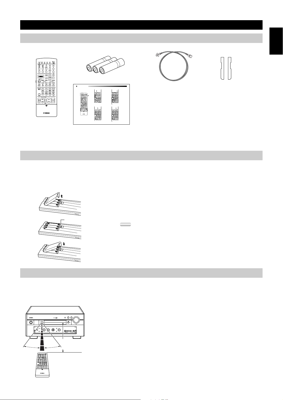
Getting Started
Checking the Package Contents
Check your package to make sure it has the following items.
RL
Alkaline Batteries (3) (LR6)
Remote Control
Quick Reference Card
■ Remote Control ■ TUNER ■ CD button (CD area)
Infrared window
LEARN
CLEAR
MACRO
SYSTEM POWER
Operational buttons
Operational buttons
RE-NAME
TRANSMIT
STANDBY
Display
Source selector
LIGHT
10 KEY/DSP
LEVEL
ON SCREEN
SLEEP
TEST
(Set 10KEY)
MACRO ON/OFF
A
button
POWER
Input buttons
Preset number 1 to 8
6CH INPUT
Preset group A through E from left.
Preset group A/B/C/D/E
Preset +/–
Sound program selector/
Numeric buttons
MUTE
■ MD/TAPE button (MD area) ■ CD-R button (CD-R area)
VOLUME +/–
EFFECT
PARAMETER/SET MENU
REC/PAUSE
POWER
Cursor buttons
DISPLAY
SEARCH
Skip Search
Cover
STOP
PLAY
PAUSE
Numeric buttons 1 to 9
Numeric button +10
Numeric button 0
TV VOL +/–, TV INPUT, and TV MUTE
(Set 10KEY)
function if you have set up the
manufacturer code for the TV Area.
INDEX
(Set 10KEY)
INDEX
(Set 10KEY)
POWER
DISPLAY
SEARCH
Skip Search
STOP
PLAY
PAUSE (/Stop)
Numeric buttons 1 to 9
CLEAR
Numeric button +10
Numeric button 0
DISC +/– (Disc Skip)
TV VOL +/–, TV INPUT, and TV MUTE
function if you have set up the
manufacturer code for the TV Area.
REC/PAUSE
POWER
DISPLAY
SEARCH
SOUND
Skip Search
STOP
PLAY
PAUSE
Numeric buttons 1 to 9
Numeric button +10
Numeric button 0
TV VOL +/–, TV INPUT, and TV MUTE
function if you have set up the
manufacturer code for the TV Area.
V655120
Power Cord
(Europe model only)
Side panel sticker
Quick Reference Guide
When finding it difficult to fit this unit onto the shelf, remove the side panels after removing the screws tightened on the side panels. Put this
sticker to cover the screw holes after tearing off the back side of the sticker.
Installing Batteries in the Remote Control
English
Insert the batteries in the correct direction by aligning the + and – marks on the batteries with the polarity illustrations (+ and –) inside the
battery compartment.
Change the batteries periodically. Do not use old batteries together with new ones.
Do not use different types of batteries (such as alkaline and manganese batteries) together. Read the packaging carefully as these different
types of batteries may have the same shape and color.
■About changing batteries
As the batteries wear out, the operating range of the remote control decreases and
the TRANSMIT indicator does not flash or its light becomes dim. When you
Reset button
notice any of these conditions, change all of the batteries.
Notes:
• If the remote control is without batteries for more than 20 minutes, or if worn out
batteries remain in the unit, the contents of the memory may be cleared.
If the memory is cleared, insert new batteries and reprogram any functions that may have
been cleared.
• After you insert new batteries, be sure to push RESET in the battery compartment using
a ball point pen or similar object before using the remote control. (This does not clear the
contents of the memory.)
Using the Remote Control
The remote control transmits a directional infrared beam. Be sure to aim the remote control directly at the remote control sensor on the main
unit to operate. When the sensor is covered or there is a large object between the remote control and the main unit, the sensor cannot receive
signals. The sensor may not be able to receive signals properly when it is exposed to direct sunlight or a strong artificial light (such as a
fluorescent or strobe light). In this case, change the direction of the light or reposition the main unit to avoid direct lighting.
VOLUME
INPUT
INPUT MODE
EFFECT
SOURCE
DVD
MD/TAPE
CD-R
D-TV/LD
TUNER
CABLE
SAT
CD
6CH
VCR 1
PHONO
INPUT
VCR 2/DVR
VIDEO AUX
Approximately 6m
(20 feet)
S VIDEO VIDEO L R OPTICALAUDIO
VIDEO AUX
STANDBY
/ON
NATURAL SOUND AV AMPLIFIER DSP-AX2
SPEAKERS
A
SILENT
BASS
EXTENSION
PHONES
B
PROCESSOR
DIRECT
BASS TREBLE REC OUT DSP PROGRAM
30°30°
■About handling the remote control
Handle the remote control with care.
Do not spill water or other liquids on the remote control.
Do not drop the remote control.
Do not leave or store the remote control in the following types of conditions:
• high humidity or temperature such as near a heater, stove or bath; or
• dusty places; or
• in places subject to extremely low temperatures.
3
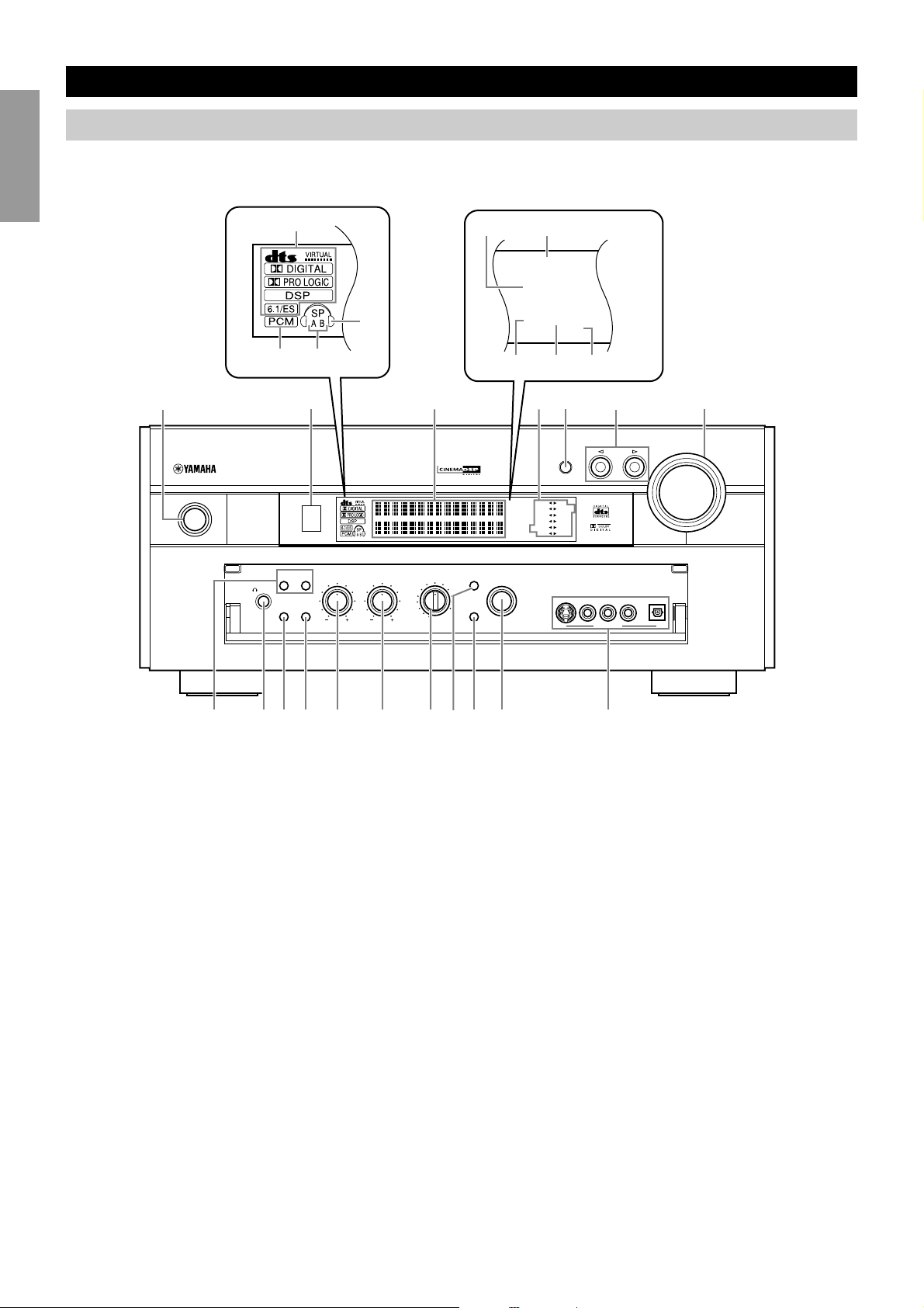
Controls and Functions
Front Panel
When you are not operating the controls behind the front panel door, close the door. To open the door, press gently on the lower part of the
panel.
IntroductionPreparationsBasic Operation
1
0
4
3
2
12 345
NATURAL SOUND AV AMPLIFIER DSP-AX2
STANDBY
/ON
SILENT
PHONES
SPEAKERS
A
BASS
EXTENSION
B
PROCESSOR
DIRECT
BASS TREBLE REC OUT
56
EFFECT
SOURCE
DVD
MD/TAPE
CD-R
D-TV/LD
CABLE
VCR 2/DVR
SAT
VCR 1
VIDEO AUX
TUNER
PHONO
CD
6CH
INPUT
DSP PROGRAM
q
M EMORY
STEREO
P.DIRECT
BASS
ZONE 2
SLEEP
8
9
7
INPUT MODE
MEMORY
D-TV/ LD
DVD
CABLE
P.DIRECT
SLEEP
SAT CD-R
VCR 1 TUNER
VCR2/ DVR
V-AUX PHONO
MD/ TAPE
CD
S VIDEO VIDEO L R OPTICALAUDIO
VIDEO AUX
STEREO
BASS
INPUT
VOLUME
Operation
Advanced
1 STANDBY/ON
2 Remote Control Sensor
3 INPUT MODE
Additional
Information
4 INPUT selector
5 VOLUME
6 PHONES
Appendix
76890q yrt
w e
Turns this unit on (On mode) and off (Standby mode). When
you turn on this unit, you will hear a click and there will be a
four to five second delay before this unit can reproduce sound.
In Standby mode, this unit consumes a small amount of power
to be ready to respond to the remote control.
Selects the type of audio signal for the selected source.
Selects a source component.
Controls the output level of all audio channels. This does not
affect the REC OUT level.
Outputs audio signals for private listening using headphones.
When you connect headphones, no signals are output to the
PREOUT jacks or the speakers.
7 SPEAKERS A/B
When SPEAKERS A/B is on, these buttons turn on the set of
Main speakers connected to the A and/or B terminals on the
rear panel.
8 BASS EXTENSION ON/OFF
When BASS EXTENSION is on, this feature boosts the bass
frequency of the left and right Main channels by +6dB (60Hz)
while maintaining overall tonal balance. This boost is useful if
you do not use a subwoofer. However, this boost may not be
noticeable if the Main speakers are set to “SMALL” and the
bass output mode is set to “SWFR.”
9 PROCESSOR DIRECT ON/OFF
When PROCESSOR DIRECT is on, BASS, TREBLE,
BALANCE, and BASS EXTENSION are bypassed,
eliminating any alteration of the original signal.
0 BASS
Adjusts the low frequency response for the left and right Main
speaker channels. Turn the control to the right to increase the
low frequency response and turn the control to the left to
decrease the low frequency response.
4

Controls and Functions
q TREBLE
Adjusts the high frequency response for the left and right Main
channels. Turn the control to the right to increase the high
frequency response.
w REC OUT
Selects the source you want to direct to the audio/video
recorder.
e EFFECT
Switches the effect speakers (Center, Front Effect, Rear and
Rear Center) on and off. If you turn off the output of these
speakers using EFFECT, all DTS and Dolby Digital audio
signals are directed to the Main left and right channels except
for the LFE channel.
Display Indicators
1 Processor indicators
When any function of DTS/VIRTUAL/Dolby Digital/Dolby
PROLOGIC/DSP/Dolby Digital Matrix 6.1/DTS ES is
operating, its indicator lights up.
2 PCM
Lights up when this unit is reproducing PCM (Pulse Code
Modulation) digital audio signals.
r 6CH INPUT
Switches between 6CH INPUT mode and normal input modes.
6CH INPUT mode takes priority over the source selected with
the INPUT selector. You cannot use DSP sound field programs
while using an external decoder.
t VIDEO AUX
Inputs audio and video signals from a portable external source
such as a video camera. To reproduce source signals from these
jacks, select V-AUX as the input source. To direct this source
to the VCR 1 and VCR 2/DVR output jacks, select VIDEO
AUX using REC OUT.
y DSP PROGRAM selector
Selects the DSP program.
6 Input source
Shows the current input source with the arrow-shaped cursor.
7 BASS
Lights up while the BASS EXTENSION is on.
8 SLEEP
Lights up while the Sleep Timer is on.
English
3 SPEAKERS A/B
Lights up according to which set of Main speakers is selected.
Both indicators light up when both sets of speakers are selected.
4 Headphones
Lights up when headphones are connected.
5 Multi-information display
Shows the current DSP program and other information when
adjusting or changing settings.
9 P. DIRECT
Lights up while the PROCESSOR DIRECT is on.
0 STEREO
Lights up when the AUTO tuning indicator is on and the unit is
receiving a strong signal for an FM stereo broadcast.
q MEMORY
Flashes to show a station can be saved.
5
Controls and Functions
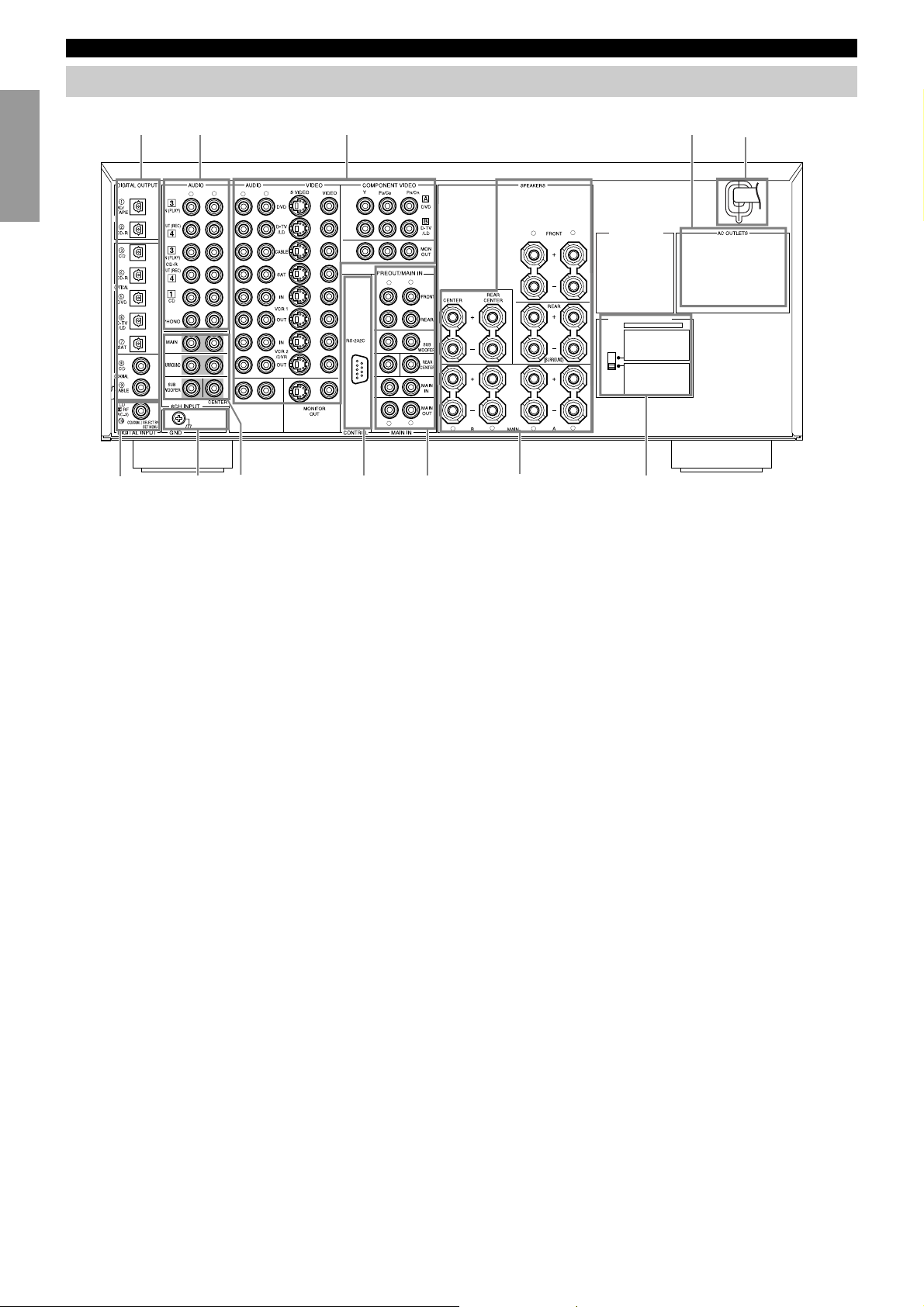
Rear panel
MD/TAPE
1
L
R
q
7
IntroductionPreparationsBasic Operation
OPTICAL
e
1 Audio component jacks
25
L
R
L
R
CENTER
TUNER
8
w9
L
R
CAUTION
SEE INSTRUCTION MANUAL FOR CORRECT SETTING.
R
L
R
R
4
8 6CH INPUT jacks
L
L
VOLTAGE SELECTOR
IMPEDAN CE SELECTOR
SET BEFORE POWER ON
FRONT
: 6ΩMIN ./ SPEAKER
REAR
: 4
: 4
REAR CENTER
: 4
CENTER
: 4
MAIN A OR B
: 8
A + B
FRONT
: 8ΩMIN ./ SPEAKER
REAR
: 8
: 8
REAR CENTER
: 8
CENTER
: 8
MAIN A OR B
: 1 6
A + B
6
0
Ω
MIN ./ SPEAKER
Ω
MIN ./ SPEAKER
Ω
MIN ./ SPEAKER
Ω
MIN ./ SPEAKER
Ω
MIN ./ SPEAKER
Ω
MIN ./ SPEAKER
Ω
MIN ./ SPEAKER
Ω
MIN ./ SPEAKER
Ω
MIN ./ SPEAKER
Ω
MIN ./ SPEAKER
(General and China models)
2 Video component jacks
4 Speaker terminals
5 AC OUTLETS
6 IMPEDANCE SELECTOR
Operation
Advanced
7 DIGITAL OPTICAL/COAXIAL jacks
Additional
Information
Use these outlets to supply power to your other audio/video
component.
9 PRE OUT/MAIN IN jacks
0 AC power cord
Connect to a power outlet.
General, China, and U.K. models cannot disconnect the AC
power cord from the unit.
q GROUND terminal
w RS232C/CTRL OUT
These are control expansion terminals for Substitute Custom
Installation use. Consult your dealer for details.
e q RF (AC-3) input jack
General and China models only.
Appendix
6
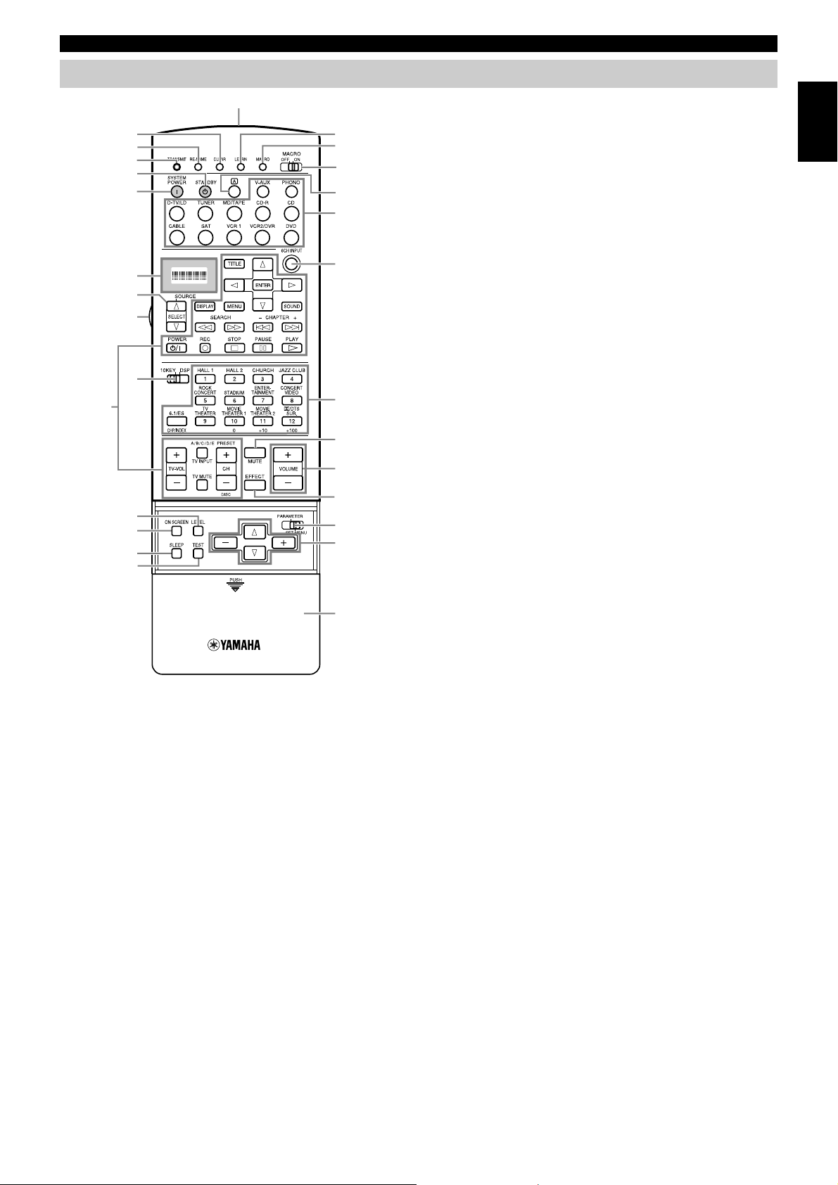
Remote Control
1
2
3
y
u
g
4
7
5
6
k
Controls and Functions
9 Operational buttons
Performs the operation selected by input selector.
0
Sound program selector/Numeric buttons
Selects the sound program.
q MUTE
Mutes the sound. Press again to restore audio output at the
previous volume level.
English
9
i
o
h
p
a
s
d
f
0
q
e
r
t
j
8
w
w VOLUME +/–
Increases or decreases the volume level.
e EFFECT
Switches the effect speakers (Center, Front, Rear, and Rear
Center) on and off.
r PARAMETER/SET MENU
Selects the PARAMETER mode or SET MENU mode.
t Cursor buttons
Selects and adjusts DSP program parameters and SET MENU
items according to the position of PARAMETER/SET MENU.
y STANDBY
Turns off the power.
u SYSTEM POWER
Turns on the power.
i Display
Displays the input or operation status.
o Source selector
Selects the source component.
1 CLEAR
Erases the content of learning.
2 RE-NAME
Renames the input name.
3 TRANSMIT
Flashes while the remote control is sending signals.
4 LEARN
Starts the learning function.
5 MACRO
Makes the MACRO setting.
6 MACRO ON/OFF
Turns the macro function on and off.
7 Input buttons
Selects the input source for playback.
8 6CH INPUT
Switches to the 6CH INPUT mode when using an external
decoder.
p 10 KEY/DSP
Selects the numeric button mode or DSP program mode.
a LEVEL
Selects the effect speaker channel to be adjusted and sets the
level.
s ON SCREEN
Selects the On-Screen Display mode for your video monitor.
d SLEEP
Sets the sleep timer.
f TEST
Outputs the test tone to adjust the speaker levels.
g Infrared window
h LIGHT
Turns the light on or off. When you press this button once, the
light turns on for about ten seconds. Press again to turn off the
light.
j Cover
k Å button
Switches the control area.
7

IntroductionPreparationsBasic Operation
Preparations
Operation
Advanced
Additional
Information
Appendix
Speaker System Configurations 9
Hookups 10
Connecting Audio Components ............................................................................. 10
Connecting Video Components ............................................................................. 12
Connecting Speakers .............................................................................................. 14
Connecting Subwoofers ......................................................................................... 16
Connecting an External Decoder............................................................................ 17
Connecting External Amplifiers............................................................................. 17
Others ..................................................................................................................... 18
On-Screen Displays (OSD) 19
OSD Modes ............................................................................................................19
Selecting the OSD Mode........................................................................................ 19
Speaker Placement 20
Speaker Settings 21
Speaker Output Levels 22
Before You Begin................................................................................................... 22
Dolby Surround Test ..............................................................................................22
DSP Test................................................................................................................. 23
8
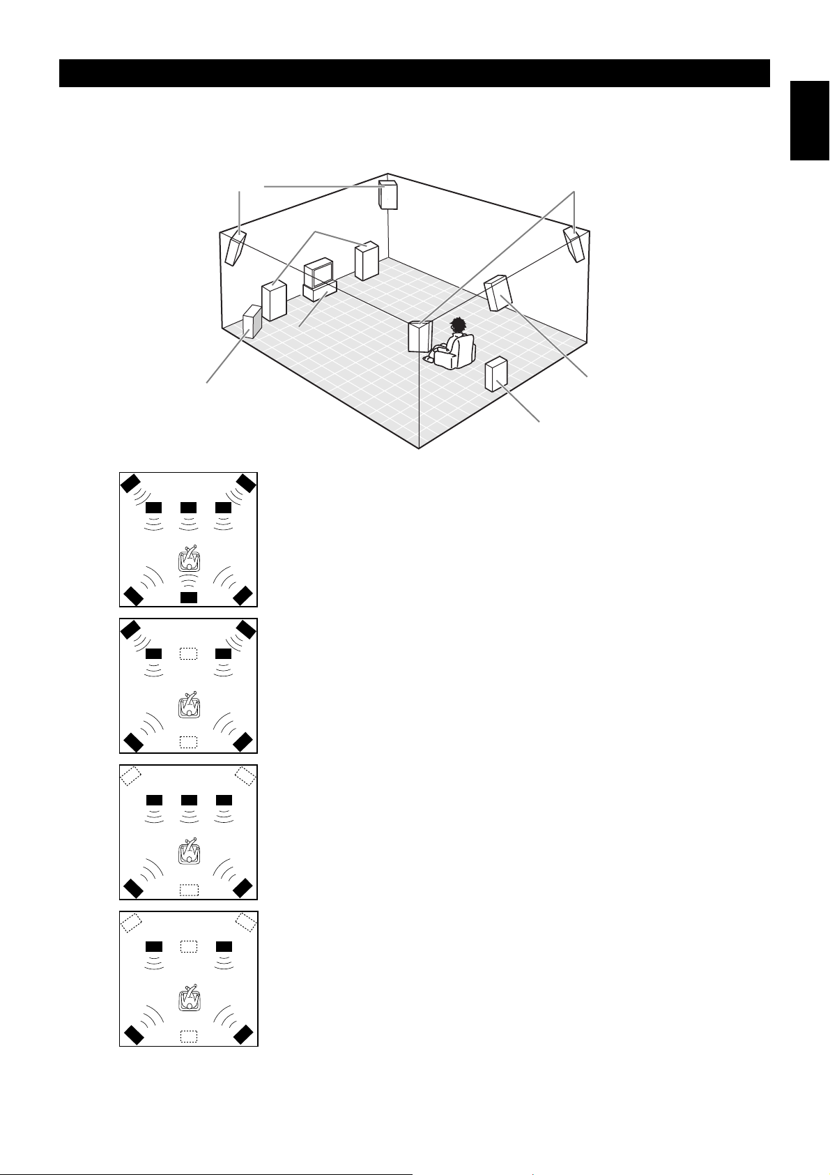
Speaker System Configurations
The most complete speaker configuration consists of eight speakers: the left and right Main speakers, a Center speaker, the left and right Rear
speakers, the left and right Front Effect speakers, and a Rear Center speaker. If you do not use eight speakers, you can direct the signals for
speakers that are not in your system to other speakers in your configuration. A Subwoofer can be used with any of these configurations to
produce a fuller sound.
English
Front Effect Speakers
Front Subwoofer
( )
Rear Speakers
Main Speakers
Center Speaker
Rear Center Speaker
Rear Subwoofer
■Eight or Seven Speaker Configuration
–Full Cinema DSP–
When you reproduce feature film software, this configuration fully expresses the
powerful and realistic sound qualities of 70 mm multitrack audio. The dialogue is
positioned as if it were coming from directly on the screen, the sound effect is
positioned slightly behind the screen, and the soundtrack music is positioned even
further behind the screen to express the width and depth of the overall presentation.
This configuration makes the most of this unit’s capability.
The Rear Center speaker is useful for playback of 6-channel Digital Surround.
■Six Speaker Configuration –Hi Fi DSP–
This configuration is used the most for audio playback with HiFi DSP. It does not
position the dialogue sound as well as a seven or eight speaker configuration.
However, it creates a dynamic DSP (Digital Sound Field Processor) sound field
which adds depth to the sound.
For this speaker configuration, change SET MENU item 1A. CENTER SP to
“NONE” and 1D. REAR CT SP to “NONE”.
■Five Speaker Configuration –Standard 5.1 Channel–
This configuration does not express the height of the sound field as well as the
seven or eight speaker configuration. However, it positions the dialogue sound as
coming directly from the screen.
For this speaker configuration, change SET MENU item 1F. FRNT EFCT SP to
“NONE” and 1D. REAR CT SP to “NONE”.
■Four Speaker Configuration
–Minimum Requirement–
In this configuration, the Center speaker signals and Front Effect speaker signals
are directed to the left and right Main speakers.
For this speaker configuration, change SET MENU item 1A. CENTER SP to
“NONE,” item 1F. FRNT EFCT SP to “NONE,” and item 1D. REAR CT SP to
“NONE”.
9

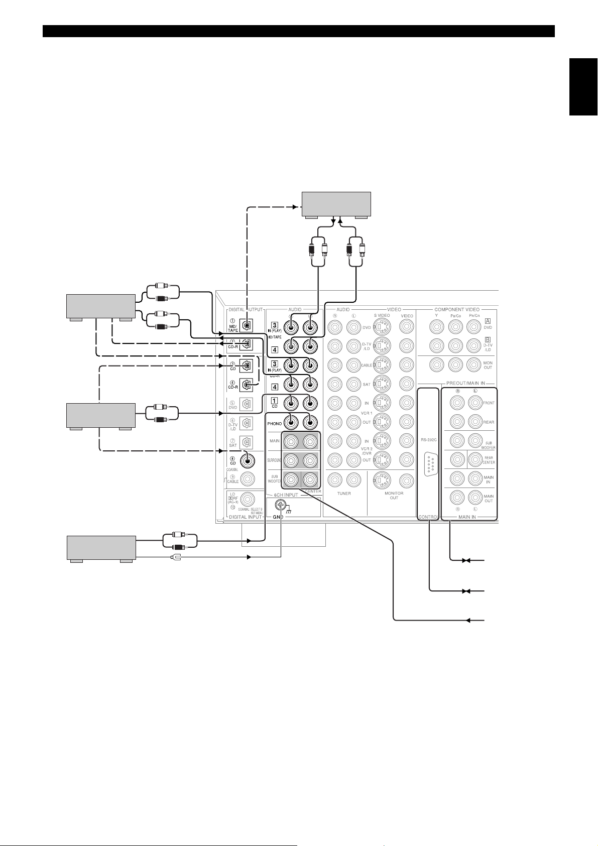
Hookups
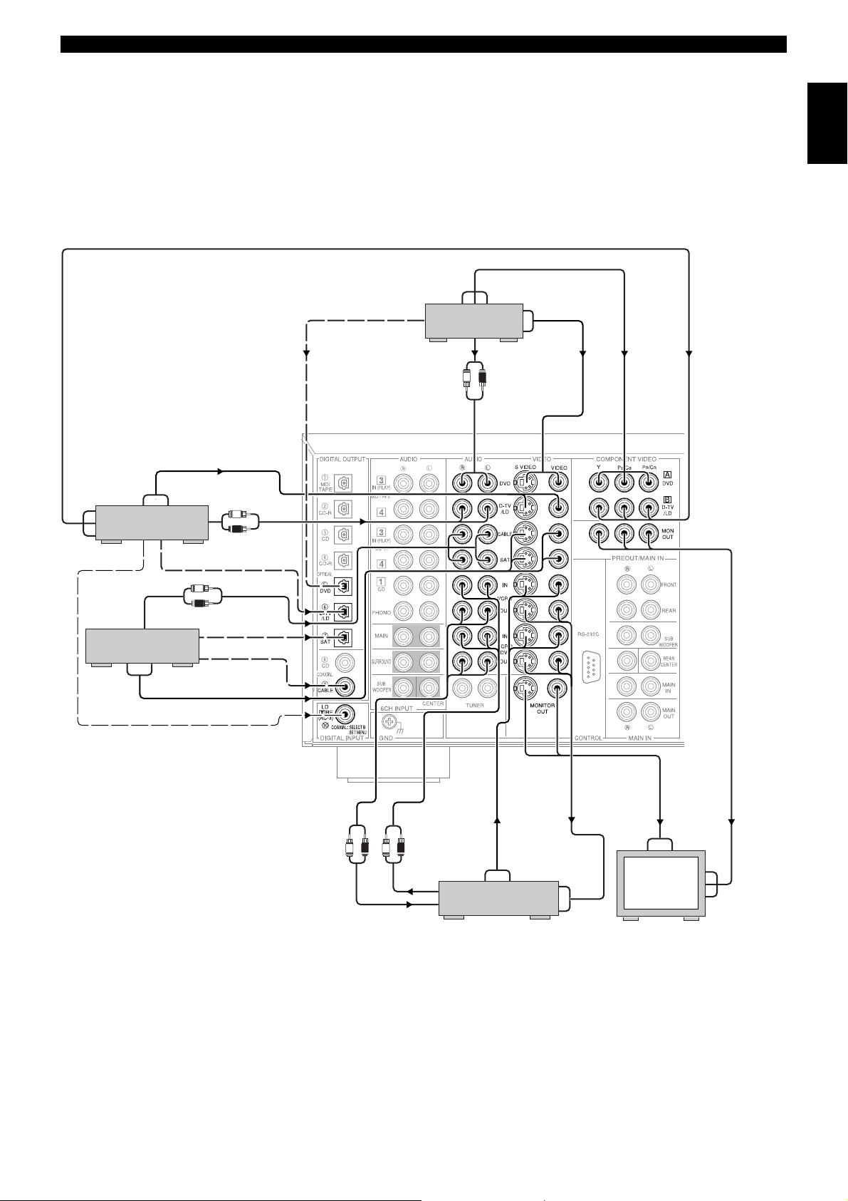
Connecting Audio Components
Before you connect any components, disconnect the power supply to all the components you plan to connect including this unit and
determine which jacks are for the left and right channels and for input and output.
IntroductionPreparationsBasic Operation
When you connect other YAMAHA audio component (such as a CD player or changer, MD deck, or tape deck), connect to terminals with
the same number labels. Yamaha applies this labelling system to all its products.
In the hookup illustrations on the following pages:
■Connecting to digital jacks
This unit has digital jacks for direct transmission of digital signals through either coaxial or fiber optic cables. You can use the digital jacks
to input PCM, DTS, and Dolby Digital bitstreams. When you connect components to both the COAXIAL and OPTICAL jacks (for CD and
CABLE) priority is given to the input signals from the COAXIAL jack. All digital input jacks are acceptable for 96 kHz/24 bit digital
signals.
■About the dust protection cap
Pull out the cap from the optical jack before you connect the fiber optic cable. Do
not discard the cap. When you are not using the optical jack, be sure to put the cap
back in place. This cap protects the jack from dust.
The OPTICAL jacks on this unit conform to the EIA standard. If you use a fiber
optic cable that does not conform to this standard, this unit may not function
properly.
■Connecting a turntable
Operation
Advanced
Additional
Information
These jacks are for connecting a turntable with an MM or high output MC
cartridge. If you have a turntable with a low output MC cartridge, use an inline
boosting transformer or MC-head amplifier when connecting to these jacks.
The GND terminal does not electrically ground the turntable. It simply reduces
noise in the signal. In some cases, you may hear less noise if you do not connect to
the GND terminal.
■Connecting a CD player
• The COAXIAL CD and OPTICAL CD jacks are available for a CD player
which has coaxial or optical digital outputs.
• When you connect a CD player to both the COAXIAL CD and OPTICAL CD
jacks, priority is given to the input signals from the COAXIAL CD jack.
■Connecting an MD or DAT deck
• When you connect a recorder to this unit, keep the deck’s power on while using
this unit. If the power is off, this unit may distort the sound from other
component.
• When you record from source component connected to this unit while this unit’s
power is off, the recorded sound may be distorted. To avoid this problem, turn
on this unit.
• When you connect a CD recorder to both the analog and digital input and output
jacks, priority is given to the digital signals.
Appendix
10
OPTICAL
OPTICAL
OUT (REC)
OUT (REC)
CENTER
L
R
L
R
L
R
L
R
L
R
L
R
OUTPUT
OUTPUT
OUTPUT
OUTPUT
INPUT
INPUT
GROUND
OPTICAL
OUTPUT
OPTICAL
INPUT
OPTICAL
INPUT
OPTICAL
OUTPUT
COAXIAL
OUTPUT
<Digital>
<Digital>
<Digital>
<Digital>
<Digital>
<Analog>
<Analog>
<Analog>
<Analog>
<Analog>
<Analog>
CD recorder
Hookups
English
MD/TAPE
recorder
(General and China models)
CD player
Turntable
to/from External
Amplifier
to/from External
Controller
from External
Decoder
11

Hookups
Connecting Video Components
Before you connect any components, disconnect the power supply to all the components you plan to connect including this unit and
determine which jacks are for the left and right channels and for input and output. After you finish all hookups, check them again to make
sure they are correct.
■About the video jacks
IntroductionPreparationsBasic Operation
There are three types of video jacks. Video signals input through the VIDEO jacks are the conventional composite video signals. Video
signals input through the S VIDEO jacks are separated into luminance (Y) and color (C) video signals. The S-video signals achieve high
quality color reproduction.
Video signals input through the COMPONENT VIDEO jacks are separated into luminance (Y) and color difference (P
signals. The jacks are also separated into three for each signal. The labels of the component video jacks may be different depending on the
component (e.g. Y, C
B, CR / Y, PB, PR / Y, B-Y, R-Y/ etc.). Component video signals provide the best quality in picture reproduction.
If your video component has an S-video output or component video output, you can
Composite VIDEO jack
connect it to this unit. Connect the S-video signal output jack on your video
component to the S-VIDEO jack or connect the component signal output jacks on
your video component to the COMPONENT VIDEO jacks.
S VIDEO jack
COMPONENT VIDEO jacks
Notes:
• Each type of video jack works independently. Signals input through the composite video,
S-video, and component jacks are output through the corresponding composite video, Svideo, and component jacks respectively.
• Use a commercially available S-video cable when connecting to the S VIDEO jacks, and
commercially available video cables when connecting to the COMPONENT VIDEO
jacks.
• When you are using the COMPONENT VIDEO jacks, check the details in the owner’s
manual that came with the component being connected.
B/CB, PR/CR) video
Operation
Advanced
Additional
Information
Appendix
12
COMPONENT
OUTPUT
VIDEO
OUTPUT
DTV/LD player
RF
OUTPUT
AUDIO
OUTPUT
Cable TV/SAT
S VIDEO
OUTPUT
S VIDEO
OUTPUT
OPTICAL
OUTPUT
VIDEO
OUTPUT
AUDIO
OUTPUT
L
R
L
R
<Analog>
SAT OPTICAL
OUTPUT
CABLE COAXIAL
OUTPUT
<Video>
<Analog>
<Digital>
<Digital>
<Digital>
<Video>
<Digital>
OPTICAL
OPTICAL
OUTPUT
OUT (REC)
OUT (REC)
DVD player
AUDIO
OUTPUT
COMPONENT
OUTPUT
L
R
<Analog>
S VIDEO
OUTPUT
VIDEO
OUTPUT
<Video>
<Component Video>
CENTER
Hookups
English
<Component Video>
RF-Signal Output*
<RF>
(General and China models only)
AUDIO
INPUT
<Analog>
<Analog>
<Video>
<Video>
AUDIO
OUTPUT
R
R
L
L
S VIDEO
OUTPUT
VIDEO
OUTPUT
S VIDEO
INPUT
VIDEO
INPUT
VCR 1/2
VIDEO
INPUT
<Video>
S VIDEO
INPUT
Monitor
COMPONENT
INPUT
* <U.K. and Europe models>
If your LD player has a Dolby Digital RF signal output jack, connect it to this unit through an external RF demodulator.
(You can connect the Dolby Digital RF signal output of your LD player to the COAXIAL jacks using the “I/O ASSIGN” on the SET
MENU.)
<Component Video>
13
Hookups
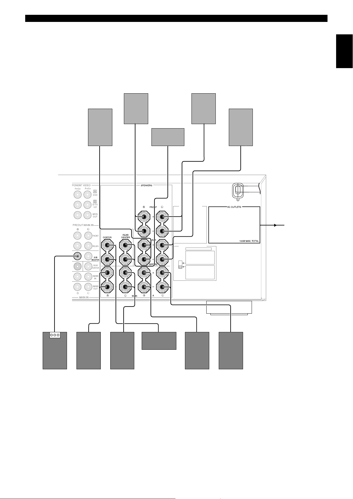
Connecting Speakers
This section explains how to connect speakers to this unit. After you finish connecting your speakers, use the SET MENU to change the
signal output settings according to the number and size of the speakers in your configuration.
Before connecting any speaker cords, identify which terminals are for the right and left channels and also the + and – polarities. If you
connect speakers with the wrong polarity (+ to –), this unit will not reproduce clear sound.
IntroductionPreparationsBasic Operation
Banana Plug
(Except for Europe and U.K. models)
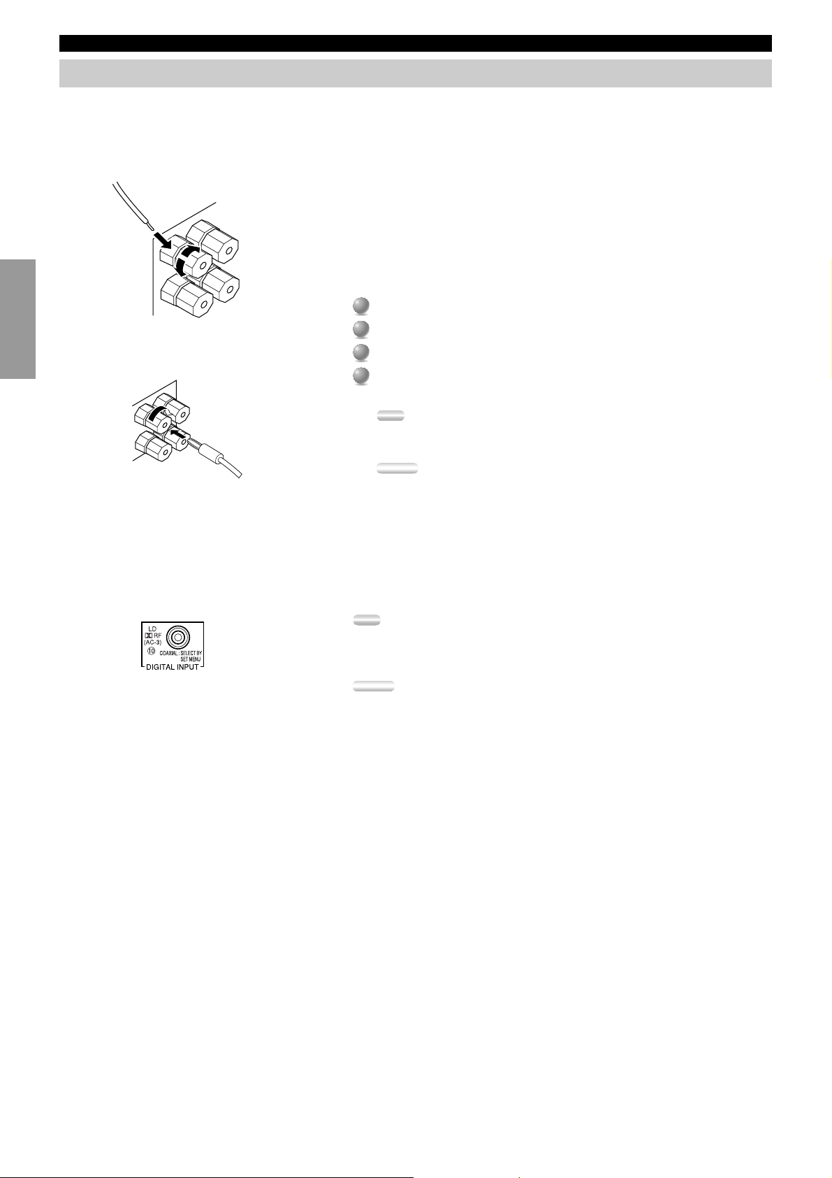
■Using speaker cords
A speaker cord is actually a pair of insulated cables running side by side. One of
the cables is colored or shaped differently, perhaps with a stripe, groove, or ridge.
To make sure you always connect speakers with the correct polarity, determine the
difference between the cables of your speaker cord, make a note of which cable
you plan to use for which polarity (+ and –), and always connect the speaker cords
consistently.
Strip off 9 mm (3/8 in.) of an inch of insulation from the ends of the cables.
1
1
Twist the exposed wires of the cable together to prevent short circuits.
2
2
3
Loosen the terminal knob by turning it counterclockwise.
3
Insert only the exposed portion of the cable into the slot in the side of the
4
4
terminal, and tighten the terminal knob.
Note:
• If your speaker cords have banana plugs, tighten the terminal knob and insert the
plug into the end of the terminal. (Except for Europe and U.K. models)
Caution:
• Connect the speaker cords with care to avoid creating a short circuit. If you turn on
the power and there is a short circuit, this unit may be damaged even though the
protection circuit automatically shuts off the power.
■About the q RF (AC-3) signal input jack <For China and General models only.>
If your LD player has an q RF (AC-3) signal output jack, connect it to the q RF (AC-3) input jack on this unit. For this connection,
change SET MENU item 7D. COAXIAL IN (10) to “LD-RF”. If q RF (AC-3) and analog signals are input at the same time, priority is
given to the RF signals. When you want to reproduce q RF (AC-3) signals, set the input mode to “D.D. RF” using INPUT MODE.
Operation
Advanced
Additional
Information
Note:
• q RF (AC-3) signals cannot be output using the REC OUT selector. When you record
sound or images from an LD player, be sure to connect the player to either the DIGITAL
OPTICAL or analog AUDIO jacks.
Caution:
• Even if you connect an LD player with an q RF (AC-3) output jack to this unit, you
cannot reproduce Dolby Digital sound from all LD discs. You must playback an LD disc
encoded with Dolby Digital signals in order to take advantage of the Dolby Digital
sound.
Appendix
14
Hookups
English
Right Rear
Speaker
Right Front
Speaker
CAUTION
SEE INSTRUCTION MANUAL FOR CORRECT SETTING.
Rear Center
Speaker
Left Front
Speaker
VOLTAGE SELECTOR
IMPEDANCE SELECTOR
SET BEFORE POWER ON
FRONT
: 6ΩMIN ./ SPEAKER
REAR
: 4ΩMIN ./ SPEAKER
REAR CENTER
Ω
: 4
CENTER
: 4ΩMIN ./ SPEAKER
MAIN A OR B
: 4
Ω
A + B
: 8ΩMIN ./ SPEAKER
FRONT
: 8ΩMIN ./ SPEAKER
REAR
: 8ΩMIN ./ SPEAKER
REAR CENTER
: 8ΩMIN ./ SPEAKER
CENTER
: 8
Ω
MAIN A OR B
: 8ΩMIN ./ SPEAKER
A + B
: 1 6ΩMIN ./ SPEAKER
MIN ./ SPEAKER
MIN ./ SPEAKER
MIN ./ SPEAKER
Left Rear
Speaker
(General and China models)
To other component
Subwoofer
system
Right Main B
Speaker
Left Main B
Speaker
Center Speaker
Right Main A
Speaker
Left Main A
Speaker
15
Hookups
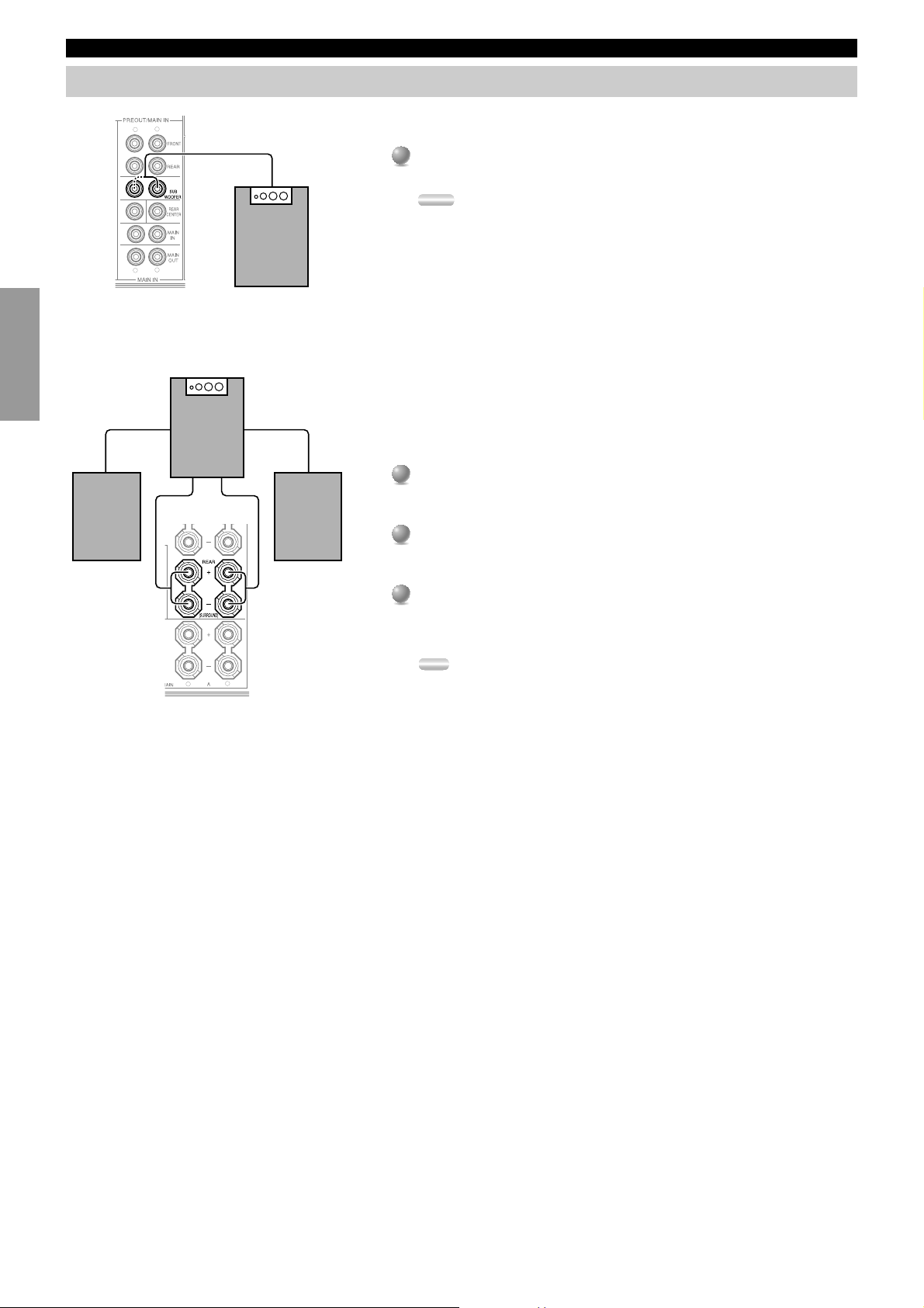
Connecting Subwoofers
IntroductionPreparationsBasic Operation
CENTER
Right Rear
Speaker
L
R
L
R
Subwoofer system
R
Subwoofer system
Left Rear
Speaker
L
■Connecting a front subwoofer
Connect the signal input jack on your subwoofer to one of the PRE OUT/
MAIN IN SUBWOOFER jacks.
Notes:
• The SUBWOOFER jacks (output) have a built-in high cut-off filter (90 Hz). When
using a powered subwoofer, set the high cut-off frequency to “MAX” on your
Subwoofer.
• Both SUBWOOFER jacks output the same signal.
■Connecting a rear subwoofer
By using both Front and Rear Subwoofers, the CINEMA-DSP sound field
programs can produce realistic movie effects with powerful, dynamic sound. To
take advantage of this dynamic sound, be sure to set the 1C. REAR L/R SP item in
the SET MENU to “LARGE”, and connect your Rear speakers and Subwoofer as
described below.
Connect the right + input terminal on your Subwoofer to the REAR R +
1
1
terminal, and the right – input terminal on your Subwoofer to the REAR R –
terminal with speaker cords.
2
Connect the left + input terminal on your Subwoofer to the REAR L +
2
terminal, and the left – input terminal on your Subwoofer to the REAR L –
terminal with speaker cords.
3
Connect your Rear speakers to the output terminals on the Rear Subwoofer.
3
Be sure to connect the Rear speakers to the Subwoofer with the correct
polarity.
Note:
• Adjust the speaker volume for the Subwoofer with the controls on the Subwoofers,
not on this unit.
Operation
Advanced
Additional
Information
Appendix
16

Hookups
Connecting an External Decoder
This unit is equipped with six additional input jacks (left and right MAIN, CENTER, left and right SURROUND and SUBWOOFER) for
discrete multi-channel input from an external decoder, sound processor, or pre-amplifier. Connect the output jacks on your external decoder
to the 6CH INPUT jacks.
Be sure to match the left and right outputs to the left and right input jacks for the main
and surround channels.
To listen to the sound from your external decoder, press 6CH INPUT on this unit or
the remote control.
Notes:
• When you select 6CH INPUT as the input source, this unit automatically turns off the
digital sound field processor, and you cannot listen to DSP programs.
• When you select 6CH INPUT as the input source, changing SPEAKER SET on the SET
MENU is not affected.
Connecting External Amplifiers
If you want to increase the power output to the speakers, or want to use another amplifier, connect an external amplifier to the PRE OUT/
MAIN IN terminals as follows.
L
R
q
English
r
q FRONT jacks
Front Effect channel line output jacks.
w REAR (Surround) jacks
Rear channel line output jacks.
e SUBWOOFER jacks
Main, Center, and Rear channel frequencies below 90 Hz are
output through these jacks. You can also direct DTS and Dolby
Digital LFE signals to this output.
Adjust the volume level of the subwoofer with the control on
the subwoofer. Subwoofer volume cannot be adjusted from this
unit.
w
e
CENTER
t
y
L
R
r CENTER jack
Center channel line output jack.
t REAR CENTER jack
Rear Center channel line output jack.
y MAIN jacks
MAIN IN jacks .......... Line input to this unit’s Main channel
When connecting to these jacks, signals input to the
preamplifier of this unit will not be output from the main
amplifier of this unit.
MAIN OUT jacks ..... Main channel line output jacks.
amplifiers.
The signals output through these jacks
are affected by BASS, TREBLE,
BALANCE, and BASS EXTENSION
settings.
17
Hookups
Others
WARNING
Do not change the IMPEDANCE
SELECTOR switch setting while the power to
IntroductionPreparationsBasic Operation
this unit is on, otherwise this unit may be
damaged.
IF THIS UNIT FAILS TO TURN ON
WHEN THE STANDBY/ON SWITCH IS
PRESSED:
The IMPEDANCE SELECTOR switch may
not be set to either end. If so, set the switch to
either end when this unit is in the standby
mode.
(General, China, and U.K. models)
VOLTAGE SELECTOR
(General and China models)
AC Power Cord
■IMPEDANCE SELECTOR switch
Select the position whose requirements your speaker system meets.
(Upper position)
FRONT EFFECT:
The impedance of each speaker must be 6Ω or higher.
REAR: The impedance of each speaker must be 6Ω or higher.
REAR CENTER:
The impedance of the speaker must be 6Ω or higher.
CENTER: The impedance of the speaker must be 4Ω or higher.
MAIN: If you use one pair of main speakers, the impedance of each speaker
must be 4Ω or higher.
If you use two pairs of main speakers, the impedance of each speaker
must be 8Ω or higher.
G.
Operation
Advanced
VOLTAGE SELECTOR
24 0
IMPEDAN CE SELECTOR
SET BEFORE POWER ON
FRONT
: 6ΩMIN ./ SPEAKER
REAR
: 6
Ω
MIN ./ SPEAKER
REAR CENTER
Ω
MIN ./ SPEAKER
: 6
CENTER
: 4
Ω
MIN ./ SPEAKER
MAIN A OR B
Ω
MIN ./ SPEAKER
: 4
A + B
: 8
Ω
MIN ./ SPEAKER
FRONT
: 8ΩMIN ./ SPEAKER
REAR
: 8
Ω
MIN ./ SPEAKER
REAR CENTER
Ω
MIN ./ SPEAKER
: 8
CENTER
: 8
Ω
MIN ./ SPEAKER
MAIN A OR B
: 8
Ω
MIN ./ SPEAKER
A + B
Ω
MIN ./ SPEAKER
: 1 6
IMPEDANCE SELECTOR switch
AC Power Cord
(Europe model only)
AC OUTLETS
(Lower position)
FRONT EFFECT:
The impedance of each speaker must be 8Ω or higher.
REAR: The impedance of each speaker must be 8Ω or higher.
REAR CENTER:
The impedance of the speaker must be 8Ω or higher.
CENTER: The impedance of the speaker must be 8Ω or higher.
MAIN: If you use one pair of main speakers, the impedance of each speaker
must be 8Ω or higher.
If you use two pairs of main speakers, the impedance of each speaker
must be 16Ω or higher.
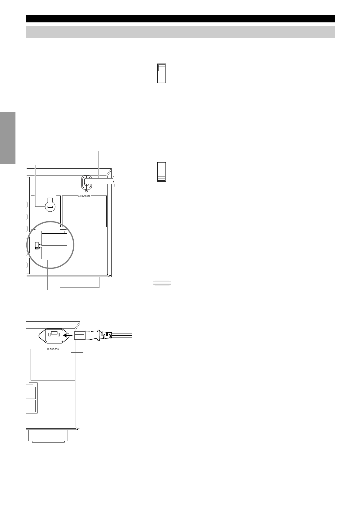
■Connecting the AC power cord
Plug in this unit to a wall outlet when all connections are complete.
Caution:
• Do not use other AC power cords than the one provided. (Europe model only)
■AC OUTLETS
Use these to connect the power cords from your other components to this unit. The
power to the switched outlets is controlled by this unit’s STANDBY/ON
(SYSTEM POWER or STANDBY on the remote). These outlets will supply
power to any connected unit whenever this unit is turned on. The maximum power
(total power consumption of components) that can be connected to AC OUTLETS
is 100 W.
■Voltage selector (General and China models)
Additional
R
Information
ER ON
./ SPEAKER
./ SPEAKER
./ SPEAKER
./ SPEAKER
./ SPEAKER
./ SPEAKER
./ SPEAKER
./ SPEAKER
./ SPEAKER
./ SPEAKER
./ SPEAKER
IN./ SPEAKER
Appendix
18
The voltage selector on the rear panel of this unit must be set for your local main
voltage BEFORE plugging into the AC main supply.
On-Screen Displays (OSD)
You can display the operation information for this unit on a video monitor. If you display the SET MENU and DSP sound field program
parameter settings on a screen, it is much easier to see the available options and parameters than it is by reading this information on the front
panel display.
If a video source is being reproduced, the OSD is superimposed over the image.
If a video source is not being reproduced (or the source component is set in the standby mode), you can set the OSD to turn on (blue
background) or off with “14 DISPLAY SET” on the SET MENU.
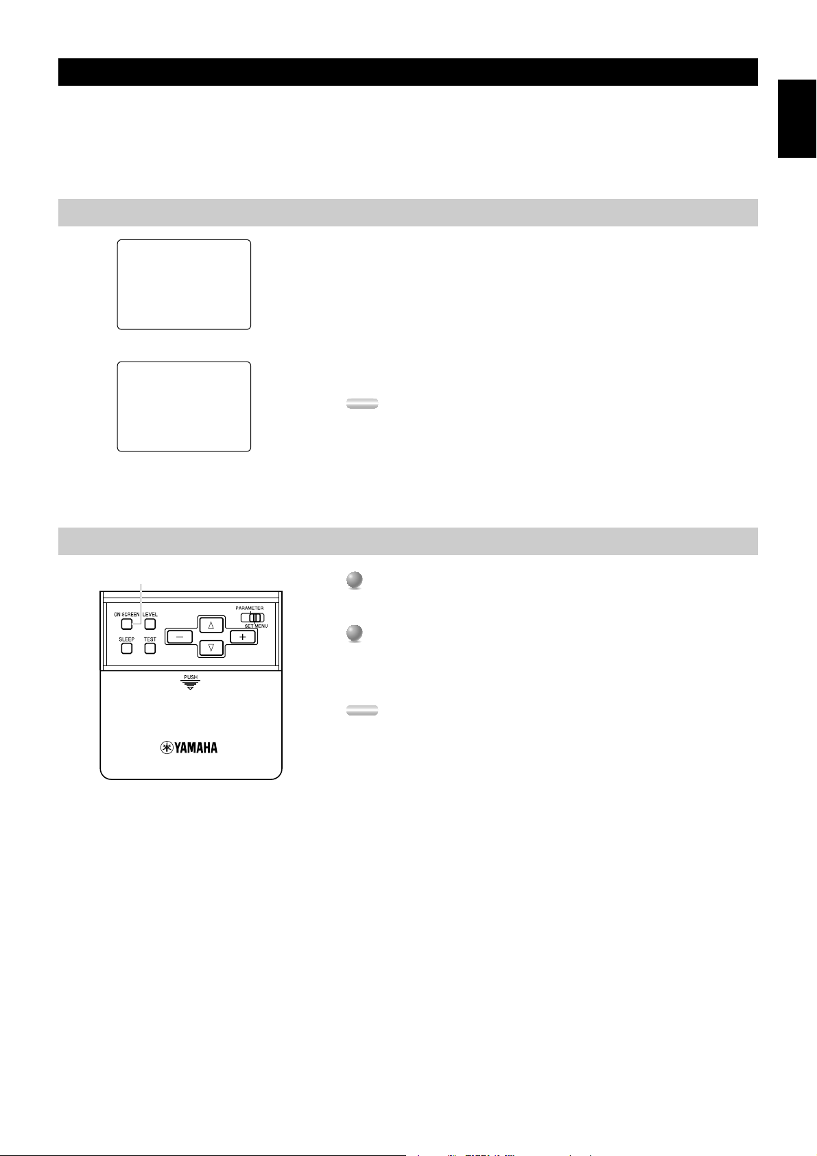
OSD Modes
English
P01 CONCERT HALL 1
≥ Europe Hall A
INIT.DLY…………30ms
ROOM SIZE…………1.0
LIVENESS…………………5
Full Display (ex.)
CONCERT HALL 1
P01
Europe Hall A
Short Display (ex.)
Selecting the OSD Mode
ON SCREEN
You can change the amount of information the OSD shows.
Full Display ..........This mode always shows the sound field program parameter
settings on the video monitor.
Short Display........ This mode briefly shows the same contents as the front panel
display at the bottom of the screen, then disappears.
Display Off ........... This mode briefly shows the “DISPLAY OFF” message at the
bottom of the screen, then disappears. Afterwards, no changes to
operations appear on the screen except those of the ON
SCREEN.
Notes:
• When you choose the Full Display mode, the INPUT selector, VOLUME, and some
other types of operation information are displayed at the bottom of the screen in the same
format as the front panel display.
• The OSD signal is not output through the REC OUT selector, and will not be recorded
with any video signal.
• The SET MENU, TEST DOLBY SUR and TEST DSP appear regardless of the OSD
mode.
When you turn on the power, the video monitor and front panel display shows
1
1
the level of the main volume for a few seconds and then switches to show the
current sound field program.
Press ON SCREEN on the remote control repeatedly to change the display
2
2
mode.
The OSD mode changes in the following order: Full Display, Short Display,
and Display Off.
Notes:
• If you choose a video input source that has component connected to both the S
VIDEO IN and composite VIDEO IN jacks, and both the S VIDEO OUT and
composite VIDEO OUT jacks are connected to a video monitor, the video signal is
output to both the S VIDEO OUT and VIDEO OUT jacks. However, the OSD is
carried only on the S-video signal. If no video signal is input, the OSD is carried on
both the S-video and composite video signals.
• If your video monitor is connected only to the COMPONENT VIDEO jacks of this
unit, the OSD is not shown. Make sure to connect your video monitor to the
COMPONENT VIDEO jack and either VIDEO or S VIDEO jacks if you would
like to see the OSD.
• Playing back video software that has an anti-copy signal or video signals with a lot
of noise may produce unstable images.
19
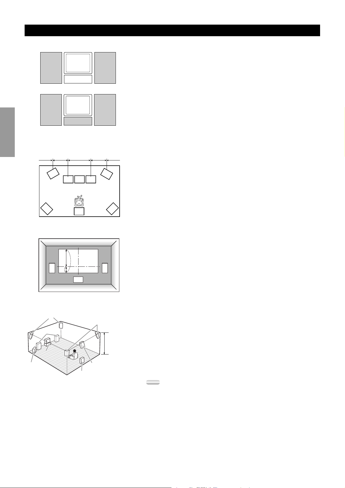
Speaker Placement
Where you place your speakers has a tremendous effect on how well your system sounds.
Main
IntroductionPreparationsBasic Operation
Speaker
RL
TV or Video
monitor
TV or Video
monitor
Center Speaker
0.5~1m1m 1m0.5~1m1.5~3m
(1~3ft)(3ft) (3ft)(1~3ft)(5~15ft)
FL
L
CR
RC
Main
Speaker
FR
RR
■Placing the Main speakers
Place the left and right Main speakers an equal distance from the main listening
position.
If you have a TV or video monitor in your system, the distance of each speaker
from each side of the TV or video monitor should be the same.
■Placing the Center speaker
If you have a TV or video monitor in your system, align the front face of the
Center speaker with the front face of the monitor. Place the speaker as close to the
monitor as possible, such as directly over or under the monitor. If you place the
speaker under the monitor, the Front Effect speakers can adjust the height of the
sound to correspond with the action on the screen (depending on the listener’s
position). If you have a projection screen in your system, place the Center speaker
under the screen. Be sure to align the speaker with the center of the screen.
■Placing the Front Effect, Rear, and Rear Center
speakers
The Front Effect speakers should be placed about 0.5~1m (1~3 feet) outside the
Main speakers and in the front of the room. They should be turned toward the main
listening position. Place the Rear speakers in the back of the room so they face the
main listening position. The Rear speakers can be placed farther apart than the
Front Effect speakers. The Front Effect and Rear speakers should be placed about
1.8m (6 feet) above the floor.
Once you begin listening to programs, continue to adjust the speaker placement
until you obtain a balanced sound from the Main speakers and the Front Effect and
Rear speakers.
Operation
Advanced
Additional
Information
Appendix
L
Front Effect speakers
Main speakers
Center
Speaker
Front
Subwoofer
1/4
1
C
Rear speakers
Rear Subwoofer
R
1.8 m (6 feet)
Rear Center speaker
■When you use a projection screen
Place the speakers as shown in the illustration.
The Main speakers should be placed about one-quarter of the way up from the
bottom of the screen.
Place the Center speaker in the center and directly under the screen. The Center
speaker provides precise dialogue localization.
When you use a projection screen with your system, the Front Effect speakers
provide better effect quality. The CINEMA-DSP sound field programs raise the
sound from the Center speaker upward and provide natural sound corresponding
with the video images.
■Placing the Subwoofers
Place the Front Subwoofer near the Main speakers. Turn it slightly toward the
center of the room to reduce wall reflections.
If you use a Rear Subwoofer, place it behind the main listening position. The
placement of the Rear Subwoofer is not critical because of the ultralow frequencies
of the sound being reproduced.
By adding a high quality Subwoofer to the speaker system configurations shown
on page 9, you can enjoy more powerful and realistic movie effects, even if your
Main speakers are large.
Notes:
• If you use different brands of speakers (with different tonal qualities) in your
configuration, the tone of a moving human voice and other types of sound may not shift
smoothly. We recommend that you use speakers from the same manufacturer or speakers
with the same tonal quality.
You can also adjust the output levels and equalization of your effect speakers using the
SET MENU.
• If you are using small speakers, the addition of a Subwoofer will reinforce the sound
effects of movies.
20
 Loading...