

Yamaha Audio DRX-1 User Manual
DVD Recorder
Enregistreur de DVD
DRX-1
OWNER’S MANUAL
U
MODE D’EMPLOI
CAUTION
ANTENNA LEAD
IN WIRE
ANTENNA
DISCHARGE UNIT
(NEC SECTION 810-20)
GROUNDING
CONDUCTORS
(NEC SECTION 810-21)
GROUND
CLAMPS
POWER SERVICE GROUNDING
ELECTRODE SYSTEM
(NEC ART 250, PART H)
GROUND CLAMP
ELECTRIC SERVICE EQUIPMENT
EXAMPLE OF ANTENNA GROUNDING AS
PER NATIONAL ELECTRICAL CODE (NEC)
RISK OF ELECTRIC SHOCK
CAUTION:TO REDUCE THE RISK OF ELECTRIC SHOCK,
REFER SERVICING TO QUALIFIED SERVICE PERSONNEL.
DO NOT OPEN
DO NOT REMOVE COVER (OR BACK).
NO USER-SERVICEABLE PARTSINSIDE.
This “bolt of lightning” indicates uninsulated material within
your unit may cause an electrical shock. For the safety of
everyone in your household, please do not remove product
covering.
The “exclamation point” calls attention to features for
which you should read the enclosed literature closely to
prevent operating and maintenance problems.
Important safety instructions
WARNING:
TO PREVENT FIRE OR SHOCK HAZARD, DO NOT EXPOSE
THIS EQUIPMENT TO RAIN OR MOISTURE.
CAUTION:
To prevent electric shock, match wide blade of plug to wide slot,
and fully insert.
ATTENTION:
Pour éviter les chocs électriques, introduire la lame la plus large
de la fiche dans la borne correspondante de a prise et pousser
jusqu’au fond.
1. Read Instructions — All the safety and operating instructions should
be read before the appliance is operated.
2. Retain Instructions — The safety and operating instructions should be
retained for future reference.
3. Heed Warnings — All warnings on the appliance and in the operating
instructions should be adhered to.
4. Follow Instructions — All operating and use instructions should be
followed.
5. Cleaning — Unplug this product from the wall outlet before cleaning.
Do not use liquid cleaners or aerosol cleaners.
Use a damp cloth for cleaning.
Exception: A product that is meant for uninterrupted service and that for
some specific reason, such as the possibility of the loss of an
authorization code for a CATV converter, is not intended to be
unplugged by the user for cleaning or any other purpose, may exclude
the reference to unplugging the appliance in the cleaning description
otherwise required in item 5.
6. Attachments — Do not use attachments not recommended by the
video product manufacturer as they may cause hazards.
7. Water and Moisture — Do not use this video product near water - for
example, near a bath tub, wash bowl, kitchen sink, or laundry tub, in a
wet basement, or near a swimming pool, and the like.
8. Accessories — Do not place this video product on an unstable cart,
stand, tripod, bracket, or table. The video product may fall, causing
serious injury to a child or adult, and serious damage to the appliance.
Use only with a cart, stand, tripod, bracket, or table recommended by
the manufacturer or sold with the video product. Any mounting of the
appliance should follow the manufacturer’s instructions and should use a
mounting accessory recommended by the manufacturer.
8A.
An appliance and cart combination should be moved with
care. Quick stops, excessive force, and uneven surfaces
may cause the appliance and cart combination to
overturn.
9. Ventilation — Slots and openings in the cabinet are provided for
ventilation, to ensure reliable operation of the video product, and to
protect it from overheating. These openings must not be blocked or
covered. The openings should never be blocked by placing the video
product on a bed, sofa, rug,
or other similar surface. This video product should never be placed near
or over a radiator or heat register. This video product should not be
placed in a built-in installation such as a bookcase or rack unless proper
ventilation is provided or the manufacturer’s instructions have been
adhered to.
10. Power Sources — This video product should be operated only from
the type of power source indicated on the marking label. If you are not
sure of the type of power supply to your home, consult your appliance
supplier or local power company. For video products intended to
operate from battery power, or other sources, refer to the operating
instructions.
11. Polarization — This product may be equipped with a polarized
alternating-current line plug (a plug having one blade wider than the
other). This plug will fit into the power outlet only one way. This is a
safety feature. If you are unable to insert the plug fully into the outlet, try
reversing the plug.
If the plug should still fail to fit, contact your electrician to replace your
obsolete outlet. Do not defeat the safety purpose of the polarized plug.
12. Power-Cord Protection — Power supply cords should be routed so
that they are not likely to be walked on or pinched by items placed upon
or against them, paying particular attention to cords at plugs,
convenience receptacles,
and the point where they exit from the appliance.
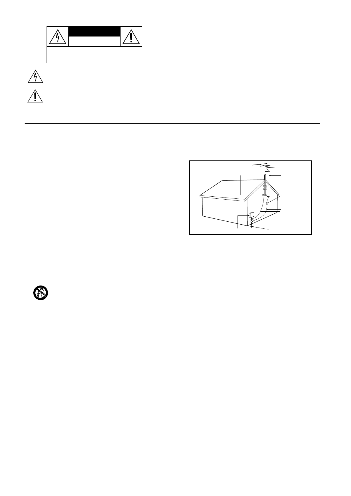
13. Outdoor Antenna Grounding — If an outside antenna or cable
system is connected to the video product, be sure the antenna or cable
system is grounded so as to provide some protection against voltage
surges and built-up static charges.
Section 810 of the National Electrical Code, ANSI/NFPA 70, provides
information with regard to proper grounding of the mast and supporting
GENERAL INFORMATION
structure, grounding of the lead-in wire to an antenna discharge unit, size
of grounding conductors, location of antenna-discharge unit, connection
to grounding electrodes, and requirements for the grounding electrode.
See Fig.A.
Fig.A.
14. Lightning — For added protection for this product during a lightning
storm, or when it is left unattended and unused for long periods of time,
unplug it from the wall outlet and disconnect the antenna or cable
system. This will prevent damage to the product due to lightning and
power surges.
15. Power lines — An outside antenna system should not be located in
the vicinity of overhead power lines or other electric light or power
circuits, or where it can fall into such power lines or circuits. When
installing an outside antenna system, extreme care should be taken to
keep from touching such power lines or circuits as contact with them
might be fatal.
16. Overloading — Do not overload wall outlets and extension cords as
this can result in a risk of fire or electric shock.
17. Object and Liquid Entry — Never push objects of any kind into this
product through openings as they may touch dangerous voltage points or
short-out parts that could result in a fire or electric shock. Never spill
liquid of any kind on the product.
18. Servicing — Do not attempt to service this product yourself, as
opening or removing covers may expose you to dangerous voltage or
other hazards. Refer all servicing to qualified service personnel.
19. Damage Requiring Service — Unplug this product from the wall
outlet and refer servicing to qualified service personnel under the
following conditions:
a. When the power-supply cord or plug is damaged.
b. If liquid has been spilled on, or objects have fallen into the product.
c. If the product has been exposed to rain or water.
d. If the product does not operate normally by following the operating
instructions. Adjust only those controls that are covered by the operating
instructions as an improper adjustment of other controls may result in
damage and will often require extensive work by a qualified technician to
restore the product to its normal operation.
e. If the product has been dropped or the cabinet has been damaged.
f. When the product exhibits a distinct change in performance - this
indicates a need for service.
20. Replacement Parts — When replacement parts are required, be sure
the service technician has used replacement parts specified by the
manufacturer or which have the same characteristics as the original part.
Unauthorized substitutions may result in fire, electric shock or other
hazards.
21. Safety Check — Upon completion of any service or repairs to this
product, ask the service technician to perform safety checks to
determine that the product is in proper operating condition.
22. Carts and Stands — The appliance should be used only with a cart or
stand that is recommended by the manufacturer.
23. Heat — The product should be situated away from heat sources such
as radiators, heat registers, stoves, or other products that produce heat.

FCC INFORMATION (for US customers)
1. IMPORTANT NOTICE: DO NOT MODIFY THIS UNIT!
This product, when installed as indicated in the instructions contained in this manual, meets FCC requirements. Modifications not
expressly approved by Yamaha may void your authority, granted by the FCC, to use the product.
2. IMPORTANT: When connecting this product to accessories and/or another product use only high quality shielded cables. Cable/s
supplied with this product MUST be used. Follow all installation instructions. Failure to follow instructions could void your FCC
authorization to use this product in the USA.
3. NOTE: This product has been tested and found to comply with the requirements listed in FCC Regulations, Part 15 for Class “B”
digital devices. Compliance with these requirements provides a reasonable level of assurance that your use of this product in a
residential environment will not result in harmful interference with other electronic devices. This equipment generates/uses radio
frequencies and, if not installed and used according to the instructions found in the users manual, may cause interference harmful
to the operation of other electronic devices. Compliance with FCC regulations does not guarantee that interference will not occur
in all installations. If this product is found to be the source of interference, which can be determined by turning the product “OFF”
and “ON”, please try to eliminate the problem by using one of the following measures:
Relocate either this product or the device that is being affected by the interference.
Utilize power outlets that are on different branch (circuit breaker or fuse) circuits or install AC line filter/s.
In the case of radio or TV interference, relocate/reorient the antenna. If the antenna lead-in is 300 ohm ribbon lead, change the
lead-in to coaxial type cable.
If these corrective measures do not produce satisfactory results, please contact the local retailer authorized to distribute this type
of product. If you can not locate the appropriate retailer, please contact Yamaha Electronics Corp., 6600 Orangethorpe Ave. Buena
Park, CA90622.
The above statements apply ONLY to those products distributed by Yamaha Corporation of America or its subsidiaries.
English
THIS DIGITAL APPARATUS DOES NOT EXCEED THE
CLASS B LIMITS FOR RADIO NOISE EMISSIONS FROM
DIGITAL APPARATUS AS SET OUT IN THE RADIO
INTERFERENCE REGULATIONS OF THE CANADIAN
DEPARTMENT OF COMMUNICATIONS.
CET APPAREIL NUMÉRIQUE N'ÉMET PAS DE BRUITS
RADIOÉLECTRIQUES DÉPASSANT LES LIMITES
APPLICABLES DANS LA RÈGLEMENT SUR LE
BROUILLAGE RADIOÉLECTRIQUES ÉDICTÉ PAR LE
MINISTÈRE DES COMMUNICATIONS DU CANADA.
NOTE TO CABLE TV SYSTEM INSTALLER:
This reminder is provided to call the Cable TV (CATV)
system installer’s attention to Article 820-40 of the NEC
(National Electrical Code) that provides guidelines for proper
grounding and, in particular, specifies that the cable ground
shall be connected to the grounding system of the building, as
close to the point of cable entry as practical.
Laser safety
This unit employs a laser. To prevent possible eye injury, only a qualified service person should remove the cover or attempt to service this
device.
USE OF CONTROLS OR ADJUSTMENTS OR PERFORMANCE OF PROCEDURES OTHER THAN THOSE SPECIFIED
HEREIN MAY RESULT IN HAZARDOUS RADIATION EXPOSURE.
LASER
Type Semiconductor laser GaAlAs (DVD)
Semiconductor laser AlGaAs (CD)
Wavelength 660 nm (DVD)
780 nm (CD)
Output Power 20 mW (DVD +RW writing)
(out of objective) 0,8 mW (DVD reading)
0,3 mW (CD reading)
Beam divergence 82 degrees (DVD)
54 degrees (CD)
For Customer Use:
Read carefully the information located on the back of your
DVD recorder and enter below the Serial No. Retain this
information for future reference.
Model No.
Serial No.__________________________
CAUTION
CAUTION
VISIBLE AND INVISIBLE LASER RADIATION.
WHEN OPEN AVOID EXPOSURE TO BEAM.
(WARNING LOCATION: INSIDE ON LASER
COVERSHIELD)
ONLY QUALIFIED SERVICE PERSONNEL
SHOULD REMOVE THE COVER OR
ATTEMPT TO SERVICE THIS DEVICE.
GENERAL INFORMATION

CAUTION
Read this before operating your unit.
1 To assure the finest performance, please read this
manual carefully. Keep it in a safe place for future reference.
2 The recommended operating temperature range for
the Recorder is from 60˚F-95˚F (Fahrenheit). Exceeding these ranges may cause unstable recording results.
Do not expose this unit to sudden temperature
changes from cold to hot, nor locate this unit in an
environment with high humidity (i.e., a room with a
humidifier) to prevent condensation inside this unit,
which may cause an electrical shock, fire, damage to
this unit, and/or personal injury.
3 Locate this unit away from other electrical appliances,
motors, or transformers to avoid humming sounds.
4 Install this unit in a well ventilated, cool, dry, clean
place — away from direct sunlight, heat sources,
vibration, dust, moisture, or cold. In a cabinet, allow
about 2.5cm (1 inch) of free space all around this unit
for adequate ventilation.
5 Avoid installing this unit in a location where foreign
objects may fall onto this unit or where this unit may
be exposed to liquid dripping or splashing. On the top
of this unit, do not place:
– Other components, as they may cause damage and/
or discoloration on the surface of this unit.
– Burning objects (i.e., candles), as they may cause
fire, damage to this unit, and/or personal injury.
– Containers with liquid in them, as they may fall,
spilling the liquid and causing an electrical shock to
the user and/or damage to this unit.
6 Do not cover this unit with a newspaper, tablecloth,
curtain, etc. in order not to obstruct heat radiation. If
the temperature inside this unit rises, it may cause
fire, damage to this unit, and/or personal injury.
7 Do not plug in this unit to a wall outlet until all con-
nections are complete.
8 Do not operate this unit upside-down. It may over-
heat, possibly causing damage.
9 Do not use excessive force on switches, knobs and/or
cords.
10 When disconnecting the power cord from the wall
outlet, grasp the plug; do not pull the cord.
11 Do not clean this unit with chemical solvents; this
might damage the finish. Use a clean, dry cloth.
12 Use only the voltage specified on this unit. Using this
unit with a higher voltage than specified is dangerous
and may cause fire, damage to this unit, and/or personal injury. YAMAHA will not be held responsible for
any damage resulting from use of this unit with a voltage other than as specified.
13 To prevent damage by lightning, disconnect the power
cord from the wall outlet during an electrical storm.
14 Do not attempt to modify or fix this unit. Contact
qualified YAMAHA service personnel when any service is needed. The cabinet should never be opened
for any reason.
15 When not planning to use this unit for long periods of
time (i.e., vacation), disconnect the AC power plug
from the wall outlet.
16 Be sure to read the “TROUBLESHOOTING” section
on common operating errors before concluding that
this unit is faulty.
17 Before moving this unit, press STANBY/ON to set the
unit in standby mode, then disconnect the AC power
plug from the wall outlet.
FOR CANADIAN CUSTOMERS
To prevent electric shock, match wide blade of plug to wide
slot and fully insert.
This Class B digital apparatus complies with Canadian ICES-003.
This digital apparatus does not exceed the Class B limits for
radio noise emissions from digital apparatus as set out in the
Radio Interference Regulations of the Canadian Department
of Communications.
Supplied Accessories
- Remote Control with separately-packed batteries
- 2-core power cord
- Component video cable
- S-Video cable
- Antenna cable
- Audio cable (2x)
- Video cable
- DVD+RW disc
If any item is damaged or missing, please inform your
supplier without delay.
Keep the packaging materials; you may need them to
transport your Recorder in the future.
CAUTION
Contents
Introduction__________________________________2
DVD Recorder ____________________________________________ 2
Cleaning discs _____________________________________________ 2
Remote control____________________________________________ 2
English
VCR Plus+ and PlusCode are registered trademarks of
Gemstar Development Corporation.The VCR Plus+ system is
manufactured under license from Gemstar Development
Corporation.
Pats. 5,307,173; 5,335,079; 4,908,713; 4,751,578; and
4,706,121
Manufactured under license from Dolby Laboratories.
“Dolby,” “Pro Logic” and the double-D symbol are
trademarks of Dolby Laboratories. Confidential Unpublished
Works.
©1992-1997 Dolby Laboratories, Inc. All rights reserved.
“DTS” and “DTS Digital Out” are trademarks of Digital
Theater Systems, Inc.
DCDi is a trademark of Faroudja, a division of Sage Inc.
This product incorporates copyright protection technology
that is protected by method claims of certain U.S. patents
and other intellectual property rights owned by Macrovision
Corporation and other rights owners.
Use of this copyright protection technology must be
authorized by Macrovision Corporation, and is intended for
home and other limited viewing uses only unless otherwise
authorized by Macrovision Corporation. Reverse engineering
or disassembly is prohibited.
TRUSURROUND, , and symbol
are trademarks of
SRS Labs,Inc. TRUSURROUND technology is manufactured
under license from SRS Labs, Inc.
Installation ___________________________________3
Connections - back of your DVD Recorder _____________________ 3
Step 1: Connecting to the antenna or Cable TV signal _____________ 3
Step 2: Connecting to a TV __________________________________ 3
Step 3: Connecting to audio equipment_________________________ 4
Step 4: Connecting to other equipment (optional) ________________ 5
Step 5: Connections - Front of your DVD Recorder (optional) ______ 6
Step 6: Power supply________________________________________ 6
Switching on ______________________________________________ 6
First time setup: Initial setup__________________________________ 7
Functional overview __________________________9
Front of recorder __________________________________________ 9
Back of Recorder _________________________________________ 10
Display__________________________________________________ 11
Remote control___________________________________________ 12
Operation___________________________________13
Important notes for operation _______________________________ 13
Loading discs _____________________________________________ 13
Disc types _______________________________________________ 13
On-screen display information _______________________________ 14
Index Picture Screen_______________________________________ 18
User preferences__________________________________________ 19
Recording ___________________________________24
Before you start recording __________________________________ 24
Manual recording of a TV channel or from a video camera ________ 24
Timer programming _______________________________________ 26
If a timer recording is incorrect ______________________________ 28
Playback ____________________________________30
Playing a DVD+RW/+R disc _________________________________ 30
Playing a pre-recorded DVD-Video disc _______________________ 30
Playing a (Super) Video CD _________________________________ 30
General features __________________________________________ 31
Special DVD+RW/+R features _______________________________ 34
Special DVD-Video features _________________________________ 34
Special VCD features ______________________________________ 35
Playing an Audio CD_______________________________________ 36
Access control_______________________________37
Child Lock (DVD and VCD)_________________________________ 37
Parental Level (DVD-Video only) _____________________________ 38
Country_________________________________________________ 39
Changing the 4-digit code ___________________________________ 39
Managing disc content (DVD+RW/+R only) ____40
Title settings _____________________________________________ 40
Disc Information Screen ____________________________________ 40
Disc Settings _____________________________________________ 41
Editing __________________________________________________ 42
Troubleshooting _____________________________45
Diagnosis program ________________________________________ 47
DVD Recorder system notes ________________________________ 47
Glossary ____________________________________48
Appendix ___________________________________49
Using your DVD Recorder remote control with your TV _________ 49
Specifications _______________________________51
CONTENTS 1
Introduction
DVD Recorder
DVD (Digital Versatile Disc) is the new storage medium
that combines the convenience of the Compact Disc with
the latest advanced digital video technology.
DVD Video uses state-of-the-art MPEG2 data compression
technology to register an entire movie on a single 5-inch
disc. DVD’s variable bitrate compression, running at up to
9.8 Mbits/second, captures even the most complex
pictures in their original quality.
The crystal-clear digital pictures have a horizontal
resolution of over 500 lines, with 720 pixels (picture
elements) to each line. This resolution is more than double
that of VHS, superior to Laser Disc, and entirely
comparable with digital masters made in recording studios.
DVD recording is the next step in video technology.
DVD+ReWritable (DVD+RW) uses phase-change media,
the same technology that formed the basis for CDReWritable. A high-power laser is used to change the
reflectivity of the recording layer. This process can be
repeated more than a thousand times. DVD+Recordable
(DVD+R) uses discs based on an organic dye, a technology
pioneered with the successful CD-Recordable format, to
produce discs that keep your data for a lifetime.
Your DVD Recorder is a Recorder and player for digital
video discs, with a two-way compatibility to the
universal DVD Video standard. This means that:
- existing pre-recorded DVD Video discs can play on
your DVD Recorder and
- recordings, made on your DVD Recorder,
can play on most DVD Video players and DVD-ROM
drives.
With it, you will be able to record TV programs or edit
and archive your own video camera recordings.
Superb digital picture and sound quality, quick access to
the tracks you have recorded and extensive playback
features contribute to a completely new video experience.
From now on you will enjoy full-length movies with true
cinema picture quality and stereo or Multi-channel sound
(depending on the disc and on your playback set-up). You
will find your Recorder remarkably easy to use, with the
on-screen display on your TV, the display on the DVD
recorder and remote control.
Cleaning discs
Some problems occur because the disc inside the
Recorder is dirty. To avoid these problems, clean your
discs regularly in the following way:
● When a disc becomes dirty, clean it with a cleaning
cloth. Wipe the disc in a straight line from the center
out to the edge.
Caution:
Do not use solvents such as benzine, thinner,
commercially available cleaners, or anti-static
spray intended for analog discs.
Do not use commercially available cleaning discs to
clean the lens, as these discs may damage the
optical unit.
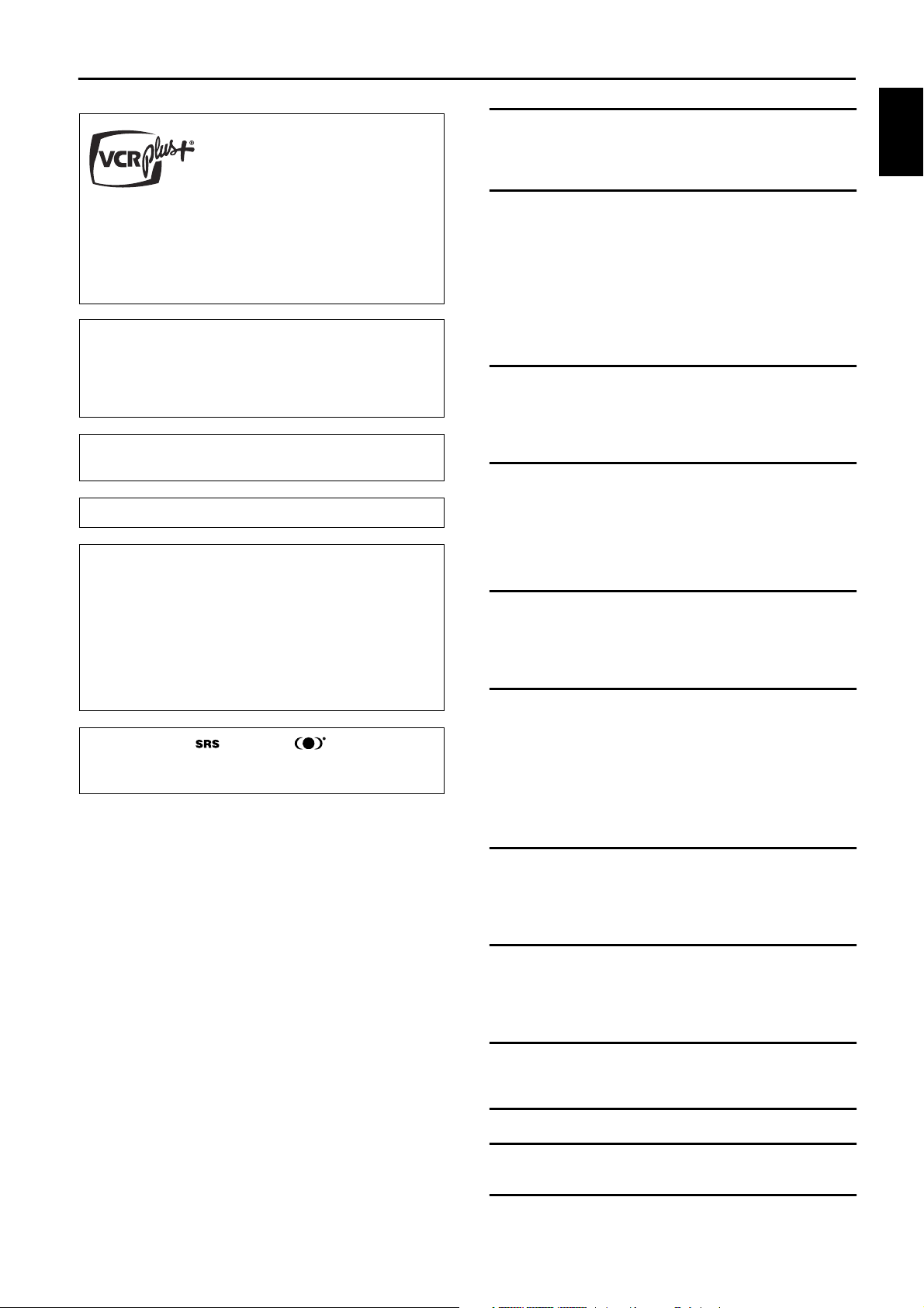
Remote control
pre-recorded DVDDVD+R(W)
DVD Video
player
DVD recorder
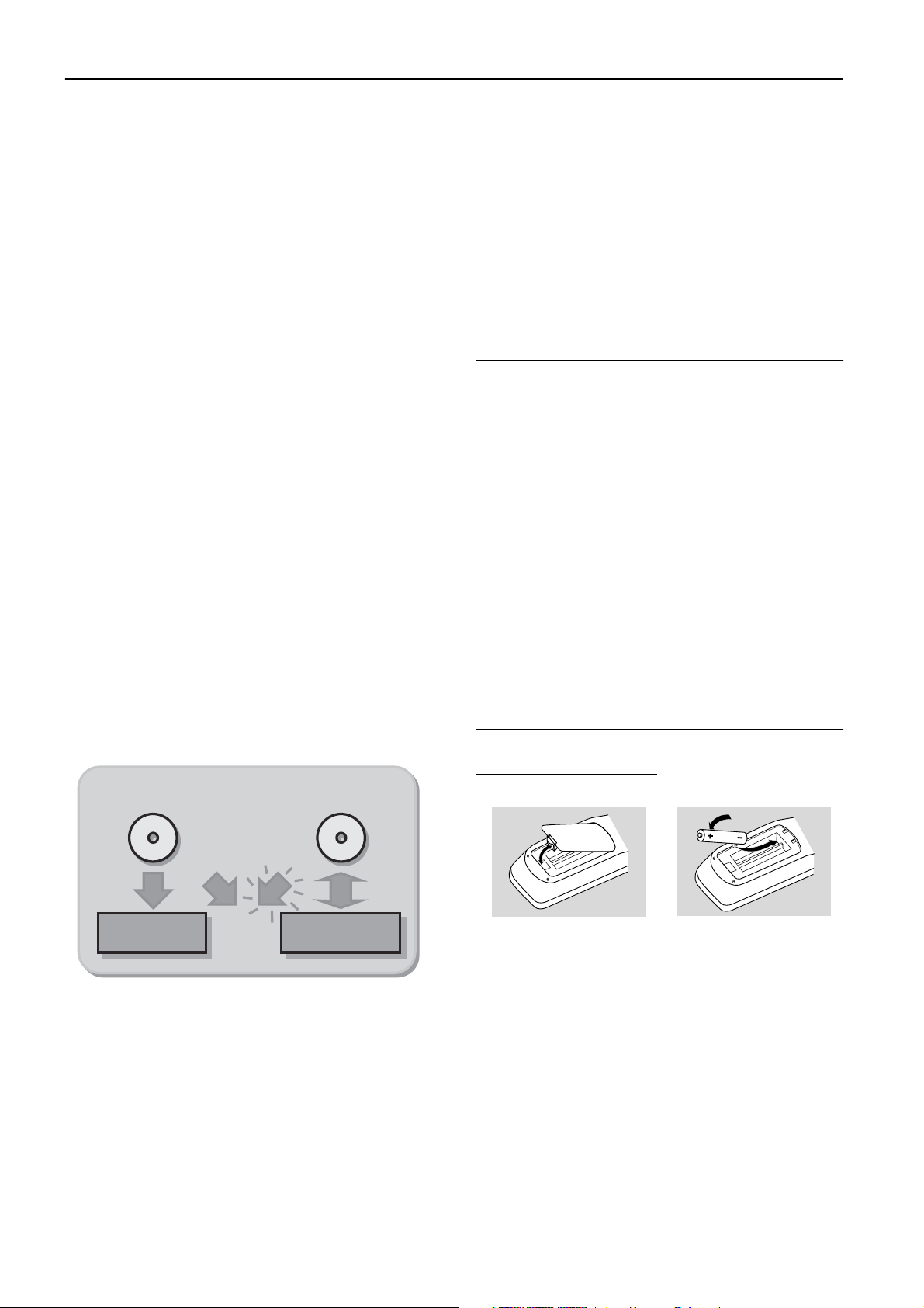
Loading the batteries
1 Remove the battery compartment cover.
2 Insert two ‘AA’ (LR-6) batteries as indicated inside the
battery compartment.
3 Replace the cover.
Caution:
Do not mix old and new batteries. Never mix
different types of batteries (standard, alkaline,
etc.). This may reduce the lifetime of the batteries.
2 INTRODUCTION
Installation
Apparatus Claims of U. S. Patent Nos.
4,631,603, 4,577,216, 4,819,098, and 4,907,093
COMPONENT VIDEO PROG
SCAN
EXT 2
YY
P
BPB
P
R
Y
L
LL
R
RR
P
B
P
R
P
R
EXT 3 EXT 3
EXT 1 EXT 1/2
IN
2
1
4
TV
Apparatus Claims of U. S. Patent Nos.
4,631,603, 4,577,216, 4,819,098, and 4,907,093
licensed for limited viewing uses only.
COMPONENT VIDEO PROG
SCAN
EXT 2
YY
P
BPB
P
R
Y
L
LL
R
RR
P
B
P
R
P
R
EXT 3 EXT 3
EXT 1 EXT 1/2
IN
RC 6
2
4
TV
1
Connections - back of your DVD Recorder
- Please refer to your TV, VCR, Stereo and any other User
Manual(s) as necessary to make the optimal connections.
- Do not connect the power cords until all other
connections are made.
- Do not connect your DVD Recorder to your TV via your
VCR. The video quality could be distorted by the copy
protection system.
- For better sound, connect the Recorder’s audio outputs
to your amplifier, receiver, stereo system or A/V
equipment. See ‘Connecting to an A/V receiver or A/V
amplifier.’
Caution:
Do not connect the Recorder’s audio output to the
phono input of your audio system. This could
damage your equipment.
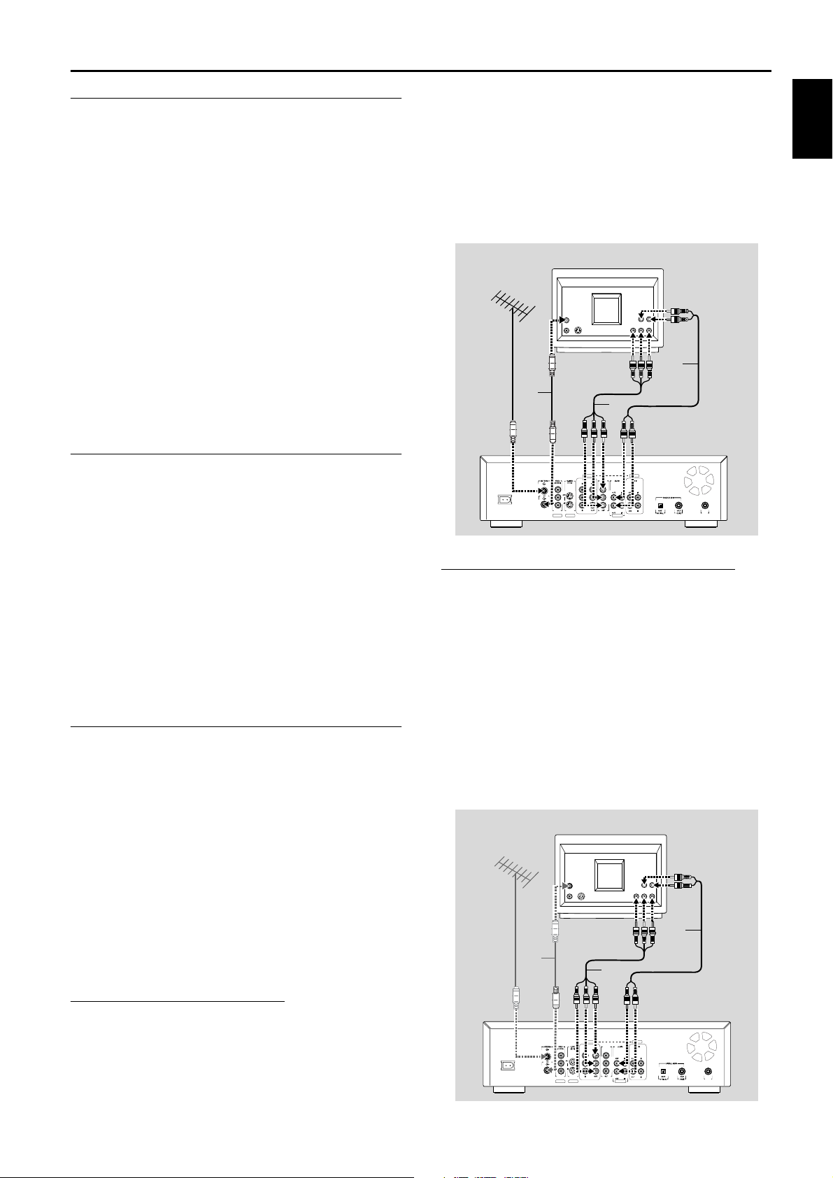
Step 1: Connecting to the antenna or Cable TV signal
● Connect the audio Left (white) and Right (red) OUT
jacks on the Recorder to the corresponding AUDIO
IN jacks on the TV using the audio cables supplied (4).
Note:
The PROG SCAN OUT jacks do not carry Closed Captioning or
V-chip signals. These features will not be available if you use the
Progressive Scan connection.
English
1 Remove the antenna cable from your TV and connect
it to the ANTENNA jack at the back of the DVD
Recorder.
2 Connect one end of the antenna cable supplied (1) to
the TV jack on the DVD Recorder and the other end
to the antenna input jack on your TV.
The antenna connection transmits TV channels through
the Recorder to the TV. You still need a video connection
to send DVD playback from the Recorder to the TV. See
‘Connecting to a TV.’
Step 2: Connecting to a TV
This DVD Recorder is equipped with Directional
Correlational Deinterlacing, known as DCDi™. DCDi was
developed by Faroudja Laboratories for ultra-high-end
home theater equipment to eliminate the jagged edges
that appear when standard interlaced video is viewed on
Progressive Scan displays. This patented technology
identifies edges at any angle in moving video images and
interpolates along the edge, pixel-by-pixel, to produce
smooth, natural looking images.
Component Video (YPBPR) connection
If your TV does not have Progressive Scan, connect the
DVD Recorder with the Component Video jacks.
● Connect the COMPONENT VIDEO (YP
jacks to the corresponding IN jacks on the TV, using
the Component Video cable supplied (2) as shown in
the drawing.
● Connect the AUDIO Left (white) and Right (red)
OUT jacks to the corresponding AUDIO IN jacks on
the TV using the audio cable supplied (4).
● Do not connect a Progressive Scan video source to
the Component Video IN jacks on your TV.
BPR
) OUT
To obtain the highest possible picture and sound quality
from your TV, use the Progressive Scan video jacks on the
DVD Recorder and TV.
Progressive Scan connection
● Connect the PROG SCAN OUT (YP
Recorder to the corresponding IN jacks on the TV,
using the Component Video cable supplied (2) as
shown in the drawing.
) jacks on the
BPR
INSTALLATION 3
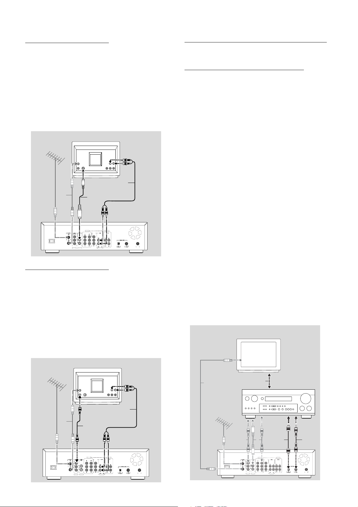
S-Video (Y/C) connection
Apparatus Claims of U. S. Patent Nos.
4,631,603, 4,577,216, 4,819 ,098, and 4,9 07,09 3
licensed for limited viewing uses only.
COMPONENT VIDEO PROG
SCAN
EXT 2
YY
P
BPB
P
R
Y
L
LL
R
RR
P
B
PRP
R
EXT 3 EXT 3
EXT 1 EXT 1/2
IN
RC 6
AMPLIFIER
76
TV
8
8
8
8
If your TV is not equipped with COMPONENT VIDEO
inputs, connect the DVD Recorder with the
S-Video (Y/C) jacks.
● Connect the S-Video (Y/C) OUT jack to the
corresponding IN jacks on the TV, using the
S-Video cable supplied (3) as shown in the drawing.
● Connect the AUDIO Left (white) and Right (red)
OUT jacks to the corresponding IN jacks on the TV
using the audio cable supplied (4).
TV
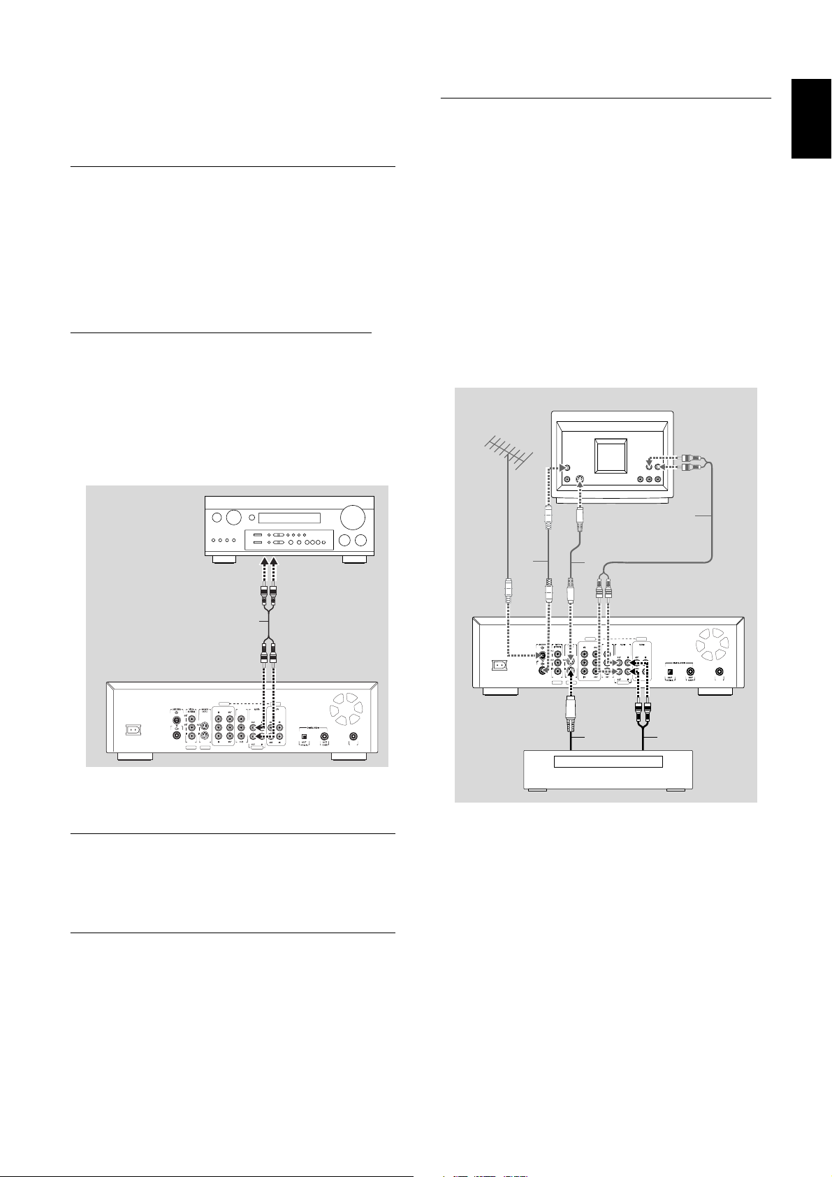
Step 3: Connecting to audio equipment
Connecting to an A/V receiver or A/V
amplifier with a digital Multi-channel
decoder
The best possible sound quality is obtained by connecting
your DVD Recorder to an Audio/Video receiver with
Multi-channel decoder (Dolby Digital, MPEG 2 and DTS).
Digital Multi-channel sound
A digital Multi-channel connection provides the optimum
sound quality. For this you need a Multi-channel A/V
receiver that supports one or more of the audio types
supported by your DVD Recorder (MPEG 2, Dolby Digital
and DTS). Check the receiver manual and the logos on the
front of the receiver.
4
Apparatus Claims of U. S. Patent Nos.
4,631,603, 4,577,216, 4,819,098, and 4,907,093
licensed for limited viewing uses only.
1
EXT 3 EXT 3
COMPONENT VIDEO PROG
P
R
EXT 2
EXT 1 EXT 1/2
3
SCAN
YY
Y
LL
P
P
BPB
P
R
L
B
R
P
R
RR
IN
Video (CVBS) connection
If your TV is not equipped with a S-Video jack, then
connect the DVD Recorder’s VIDEO (CVBS) OUT jack to
your TV.
● Connect the VIDEO (CVBS) OUT jacks (yellow)
to the corresponding IN jacks on the TV using the
video cable supplied (5) as shown in the drawing.
● Connect the AUDIO Left (white) and Right (red)
OUT jacks to the corresponding IN jacks on the TV
using the audio cable supplied (4).
TV
● Connect one of the DVD Recorder’s DIGITAL
AUDIO OUT jacks to the corresponding IN jacks on
the receiver. Use a digital coaxial cable (6) or a digital
optical audio cable (7).
● Connect the recorder’s component video, S-Video or
Video (CVBS) OUT jack to the corresponding IN jack
of your amplifier. Then make the same connection
between your amplifier and your TV (8).
● You can connect your VCR’s audio/video IN/OUT
jacks to your amplifier. Refer to the manual supplied
with your amplifier.
Note:
If you use a connection that does not match the capabilities of
your receiver, the receiver will produce a strong, distorted
sound. The audio type of the current DVD disc will appear in
the Status Window when you change the language.
Six Channel Digital Surround Sound via digital connection can
only be obtained if your receiver has a Digital Multi-channel
decoder.
1
5
EXT 3 EXT 3
COMPONENT VIDEO PROG
YY
PBP
B
P
P
R
R
EXT 2
EXT 1 EXT 1/2
SCAN
Y
LL
P
L
B
R
P
R
RR
4
IN
RC 6
Apparatus Claims of U. S. Patent Nos.
4,631,603, 4,577,216, 4,819,098, and 4,907,093
licensed for limited viewing uses only.
4 INSTALLATION
If you cannot connect your DVD Recorder to an A/V
Apparatus Claims of U. S. Patent Nos.
4,631,603, 4,577,216, 4,819,098, and 4,907,093
licensed for limited viewing uses only.
COMPONENT VIDEO PROG
SCAN
EXT 2
YY
P
BPB
P
R
Y
L
LL
R
RR
P
B
P
R
P
R
EXT 3 EXT 3
EXT 1 EXT 1/2
IN
RC 6
Set top bo x
TV
1
3
3 4
4
receiver with a Multi-channel decoder, choose one of the
following alternatives.
Connecting to a receiver equipped with two channel digital stereo (PCM)
● Connect one of the Recorder’s DIGITAL AUDIO
OUT jacks to the corresponding IN jack on your
receiver. Use the supplied yellow video (CVBS) cable
or an optional digital optical audio cable.
● After installation set Digital Output to PCM only (see
‘User preferences.’)
Step 4: Connecting to other equipment (optional)
To connect other devices to the Recorder, use the
available IN jacks on the back of the Recorder.
-Set top box (cable box or satellite receiver)
-VCR
-DVD Video player
Most pre-recorded video cassettes and DVD discs are
copy protected. If you try to copy them, the
DVD Recorder display will show ‘COPY PROTECT.’
English
Connecting to a receiver equipped with Dolby Pro Logic
● Make a video connection between the DVD Recorder
and the TV.
● Then connect the Recorder’s Left and Right AUDIO
OUT jacks to the corresponding inputs on the Dolby
Pro Logic Audio/Video receiver, using the audio cable
supplied (4).
AMPLIFIER
4
EXT 3 EXT 3
COMPONENT VIDEO PROG
SCAN
YY
Y
LL
P
Apparatus Claims of U. S. Patent Nos.
4,631,603, 4,577,216, 4,819,098, and 4,907,093
licensed for limited viewing uses only.
P
R
EXT 2
EXT 1 EXT 1/2
P
BPB
P
R
L
B
R
P
R
RR
● Make the appropriate Sound settings for Analog
Output in the user preferences menu.
Connecting to a TV with a Dolby Pro Logic decoder
● Connect the Recorder to the TV as described in
chapter ‘Connecting to a TV.’
Connecting to a receiver with two channel analog stereo
● If you have a receiver with only two-channel analog
stereo and none of the above mentioned sound
systems, connect the Left and Right AUDIO OUT
jacks of the DVD Recorder to the corresponding
AUDIO IN jacks on your receiver, amplifier or stereo
system. Use the audio cable supplied (4).
This recorder is not equipped with CBCT or C3
technology to select channels on a set top box
automatically.
IN
Do not connect a Progressive Scan video source to the
COMPONENT VIDEO IN jacks (EXT3). The DVD
Recorder cannot record Progressive Scan video signals.
Do not connect the Recorder to a VCR, then connect the
VCR directly to the TV. If you are not using the DVD
Recorder, turn off its power to avoid interfering with VCR
playback.
INSTALLATION 5
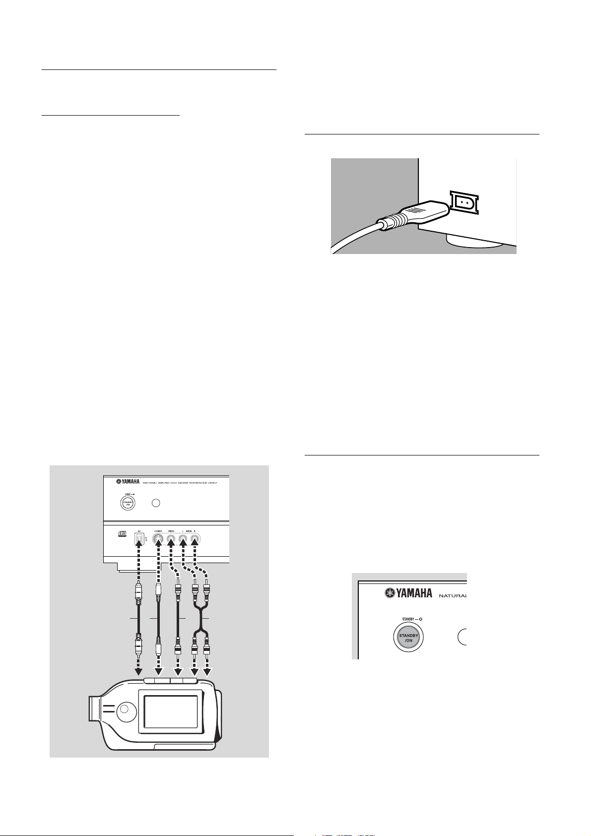
Step 5: Connections - Front of your DVD Recorder (optional)
Video camera connection
● If you have a DV or Digital 8 video camera, connect
the i-link DV input jack on the Recorder (1) to the
corresponding output jack on the video camera using
the i-link cable of your video camera.
This connection enables digital recording from the
following devices:
–DV or Digital 8 video camera
– Digital video deck
–Personal computer with DV output
–DVD recorder with DV output
● If you have a Hi-8 or S-VHS(C) video camera, connect
the DVD Recorder’s S-VIDEO IN jack to the
corresponding OUT jack on the video camera. Use
the S-Video cable supplied (2).Then connect the
AUDIO Left (white) and Right (red) IN jacks of the
DVD Recorder to the corresponding OUT jacks on
the video camera using the AUDIO cable supplied (4).
● Otherwise, connect the VIDEO IN jack on the
DVD Recorder (yellow) to the corresponding OUT
jack on the video camera. Use the video cable
supplied (3). Then connect the AUDIO Left (white)
and Right (red) IN jacks of the DVD Recorder to the
corresponding OUT jacks on the video camera using
the AUDIO cable supplied (4).
● If your video camera has mono sound, use only the
left audio connector. In this case the sound will be
recorded on both audio channels.
Notes
You will need only one video connection and one audio
connection: only the i-link DV connection carries both video and
audio. You may not use all the jacks on the DVD Recorder.
Step 6: Power supply
● Make sure all necessary connections are made before
connecting the DVD Recorder to the power supply.
● Plug the supplied power cable into the Power jack on
the back of the Recorder.
● Connect the power cord to an AC outlet.
Note:
Make sure the local power voltage matches the required 110V.
When the Recorder is in the ‘standby/power off’ position,
it is still consuming some power. If you wish to disconnect your
DVD Recorder completely from power, remove the power cord
from the AC Outlet.
When the DVD Recorder is disconnected from the power,
TV channels and timer data usually will be stored one year.
1
32
Video camera
Video camera
Switching on
● Switch on the TV and the amplifier, then select the
TV’s Video In channel or the channel you have chosen
for video playback
● Press STANDBY/ON to turn on the Recorder.
➤ The Recorder display lights. If you have not yet
installed your DVD Recorder, it will enter ‘Initial
setup.’ You will have to set your personal preferences.
4
6 INSTALLATION

First time setup: Initial setup
Initial setup
Subtitle language
Press OK to continue
English
Español
Français
Português
Italiano
Initial setup
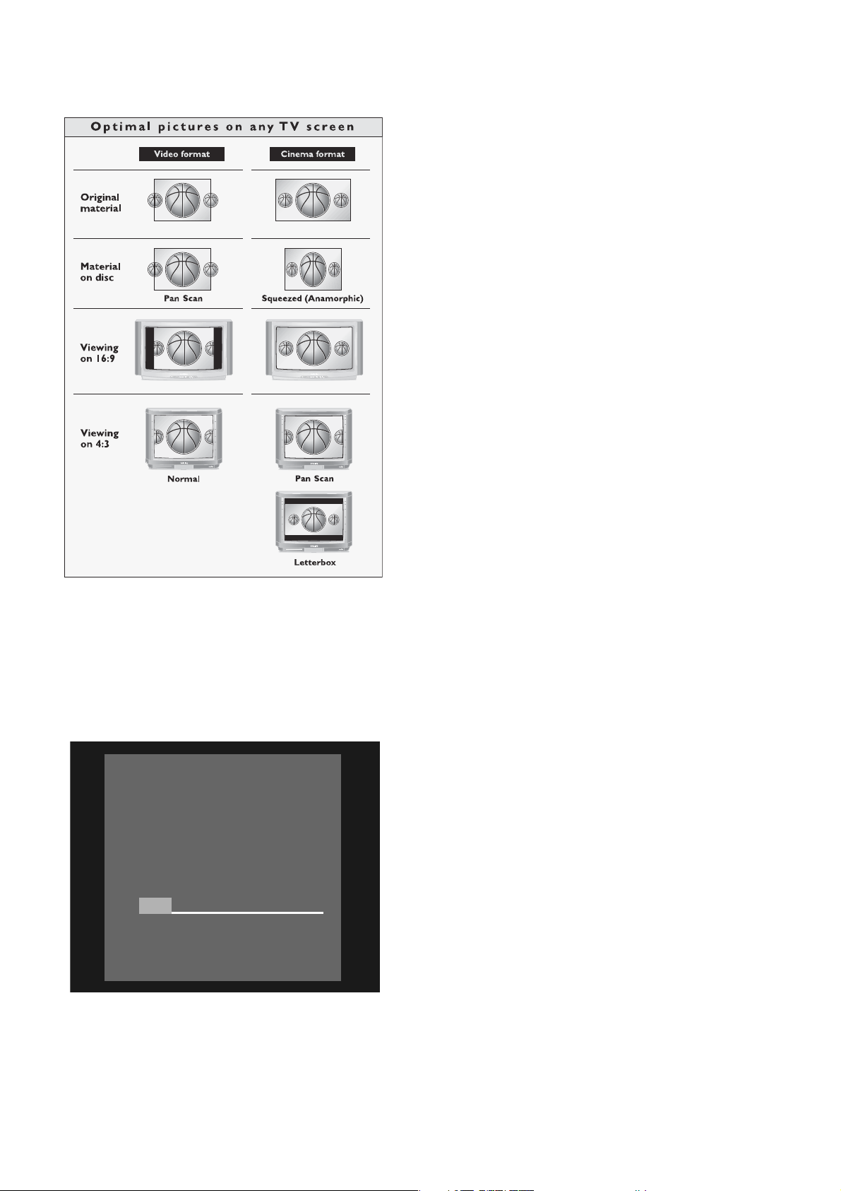
TV Shape
Press OK to continue
4:3 letterbox
4:3 panscan
16:9
After switching on the DVD Recorder for the very first
time, the ‘Initial setup screen’ will appear. In initial setup,
you may have to set your preferences for some of the
Recorder features. If the initial setup screen does not
appear, your DVD Recorder has been installed already. You
may still change the preferences via the ‘installation menu.’
Note:
Preferences have to be set in the order in which the item menus
will appear on the screen.
The ‘Initial setup’ will only be concluded after the preferences
for the last item have been confirmed.
If the Recorder is switched off while setting user preferences, all
preferences have to be set again after switching on the
Recorder again.
Manual setting
When a menu is displayed:
● Use w/v (down/up cursor) to go through the options
in the menu. The selected option will be highlighted in
white text.
● Use ENTER/OK to confirm your selection and move
to the next menu.
Subtitle language
The subtitles of DVD-Video discs will be in the language
you choose if it is available on the current disc. If not,
there will be no subtitles, or the subtitles will revert to the
default subtitle language on the disc.
TV Shape
English
The following items may be set in Initial setup:
Menu language
The DVD Recorder’s system menus will be displayed in
the language you choose.
Initial setup
Menu language
English
Español
Français
Press OK to continue
Audio language
The sound of DVD-Video discs will be in the language you
choose, if it is available on the current disc. If not, speech
will revert to the first spoken language on the disc. Also,
the DVD disc menu will be in the language you choose, if it
is available on the disc.
Initial setup
You can choose:
- 16:9 if you have a wide screen (16:9) TV.
- 4:3 if you have a regular (4:3) TV. In this case you can also
choose between:
- Letterbox for a ‘wide-screen’ picture with black
bars at the top and bottom,
- Pan Scan, for a full-height picture with the sides
trimmed. If a disc has Pan Scan, the picture moves
(pans) horizontally to keep the main action on the
screen.
Audio Language
English
Español
Français
Português
Italiano
Press OK to continue
INSTALLATION 7
Automatic TV Channel Search
Make sure the antenna is connected to the DVD Recorder.
See ‘Connecting to the antenna.’ Your DVD Recorder will
search for all TV channels that are available in your area.
It stores channels in the order in which they are found.
● Press ENTER/OK to confirm.
➤ Automatic search and installation starts. This can
take several minutes.
Installation
Auto Ch.Programming
Searching for TV channels
000 Channels found
Please wait
➤ When Automatic search and installation is complete
‘Auto ch. search complete XXX Channels found’
appears on the TV screen.
● Press SYSTEM MENU to exit the Auto channel
programming menu.
Initial setup is now complete. You can still adjust the
settings. See ‘User preferences.’
8 INSTALLATION
Functional overview
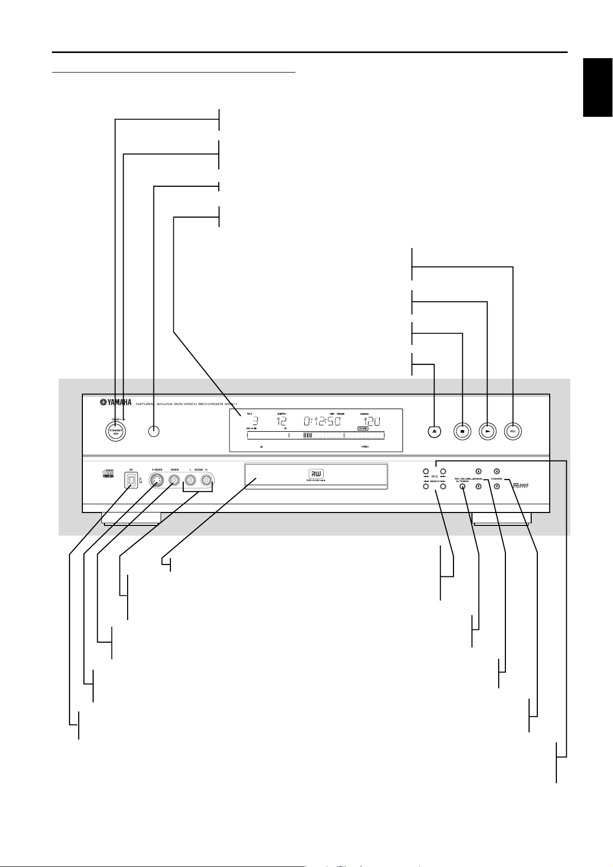
Front of recorder
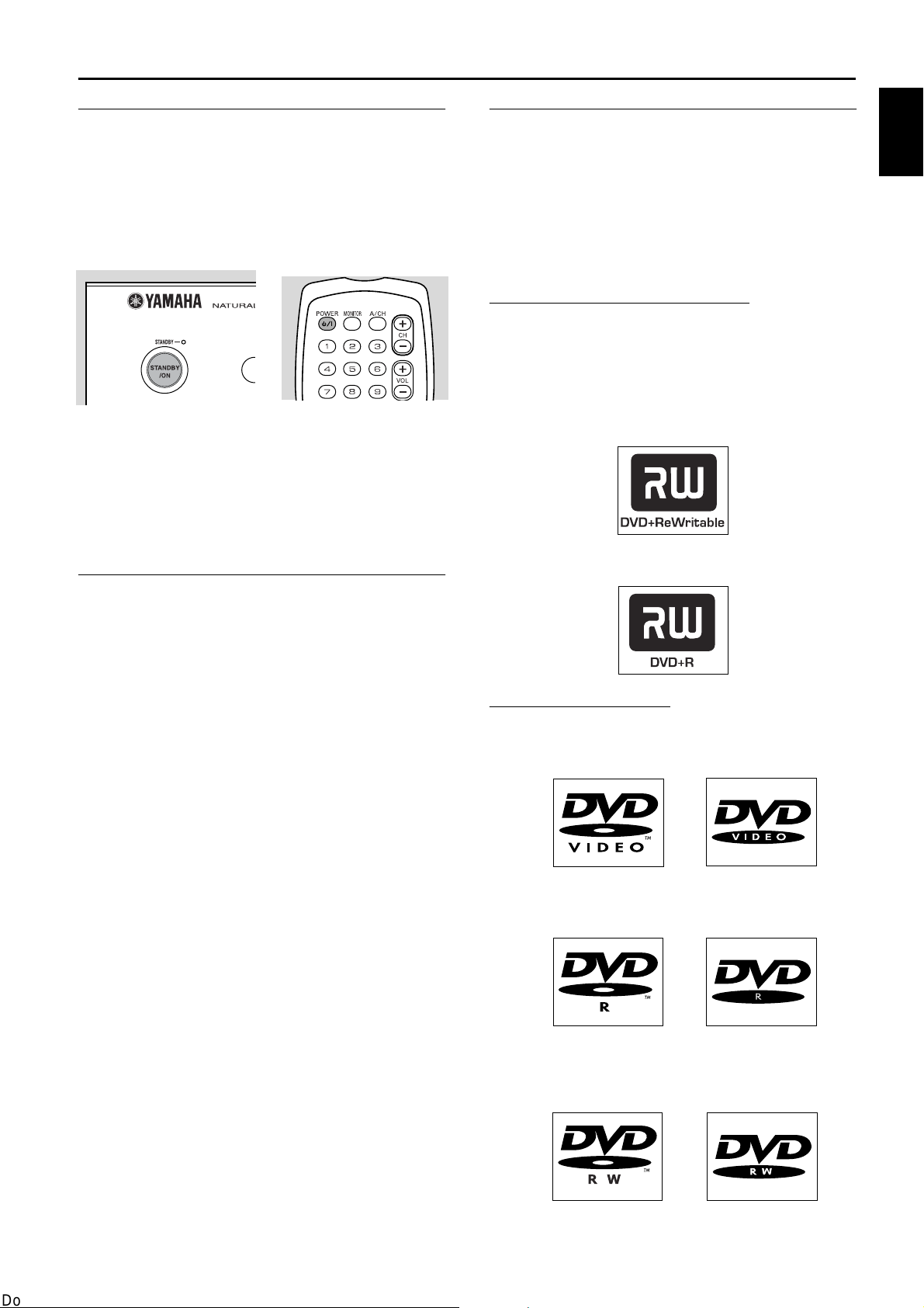
STANDBY/ON
- switches the Recorder On or to standby mode (off)
STANDBY indicator
- lights red when the Recorder is in standby mode; Recorder is not operable
- lights green when the Recorder is operable
Infrared remote control receiver
DISPLAY
- displays the current status of the Recorder
REC
- recording of the selected channel
or source
(play)
- starts disc play
2
English
Disc tray
AUDIO In (Left/Right) (CAM1/2)
- Audio left/right input jack to
connect a video camera or video
Recorder
VIDEO In (CVBS) (CAM2)
- Video input jack to connect a
video camera or video Recorder
S-VIDEO In (CAM1)
- Video input jack to connect a
video camera or video Recorder
DV (CAM3)
- Audio/Video input jack to connect a digital
video camera
- stops disc playback or recording
9 (stop)
/ (open/close)
- opens/closes the disc tray
DIGITAL
SEARCH
- 5 search backward
during disc playback
- 6 search forward
during disc playback
REC VOLUME AUTO/MAN
- to adjust the recording volume
level automatically or manually
MANUAL
- 34to increase/decrease the
recording volume level
CHANNEL
- to select TV channels manually
When the Recorder is in monitor mode.
TITLE
- ∞ selects previous title/chapter/track/index
or beginning of current title/chapter/track/index
- § selects next title/chapter/track/index
FUNCTIONAL OVERVIEW 9
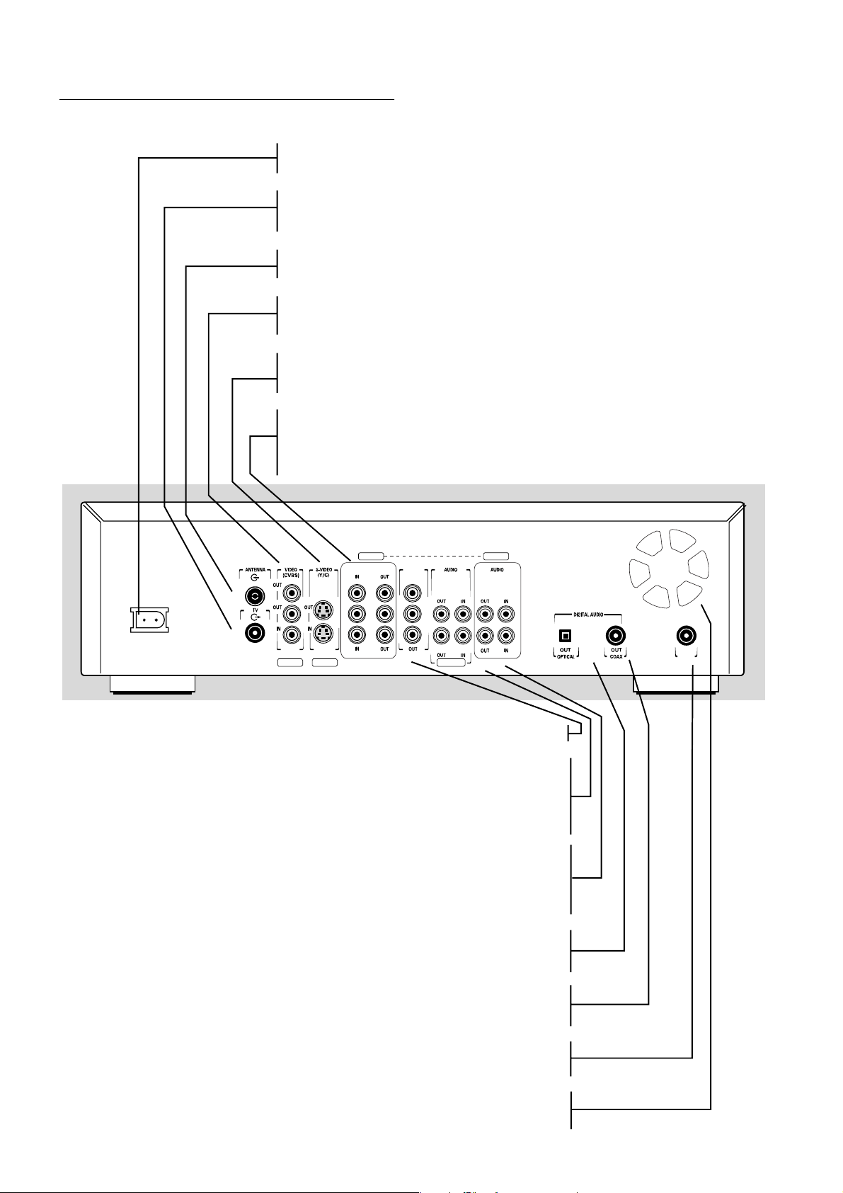
Back of Recorder
Power jack
- connection to the power outlet
TV
- RF connection to TV (does not carry the video output signal of the Recorder)
ANTENNA
- RF connection to antenna/cable TV signal
VIDEO (CVBS)
- 2 x OUT: for connection to a TV, receiver or amplifier with CVBS video inputs
- IN: for connecting a video source with CVBS outputs
S-VIDEO (Y/C)
- OUT: for connection to an amplifier, TV or receiver with S-Video inputs
- IN: for connecting a video source with S-Video outputs
COMPONENT VIDEO (YPBPR) OUT
- for connection to an amplifier, TV or receiver with component video (YP
BPR
) inputs
COMPONENT VIDEO (YPBPR) IN
- for connection to a source with component video (YPBPR) outputs
EXT 3 EXT 3
COMPONENT VIDEO PROG
P
B
P
R
EXT 2
EXT 1 EXT 1/2
SCAN
YY
P
B
P
R
Y
P
B
OG
P
R
LL
RR
L
R
PROG SCAN (Progressive Scan)
- for connection to a TV with progressive scan (480p) input
AUDIO OUT L/R
connection to an amplifier, receiver, stereo system or to a TV
AUDIO IN L/R
- connection to the audio output of a video source of which the video output is
connected to the rear CVBS video input (EXT2) or to the rear S-Video input (EXT 1)
AUDIO OUT L/R
- connection to an amplifier, receiver, stereo system or a TV
AUDIO IN L/R
- connection to the audio output of a video source of which the video output
is connected to the component video input (EXT 3)
OUT OPTICAL
- connection to an amplifier, receiver or stereo system
with a digital (optical) audio input
RC 6
IN
- connection to an amplifier, receiver or stereo system
- for connection to a media control system
- allow the DVD Recorder to cool. Do not block the vents. Leave at least one inch
10 FUNCTIONAL OVERVIEW
OUT COAX (coaxial)
with a digital (coaxial) audio input
IN RC6
VENTILATION OPENINGS
space free around the vents
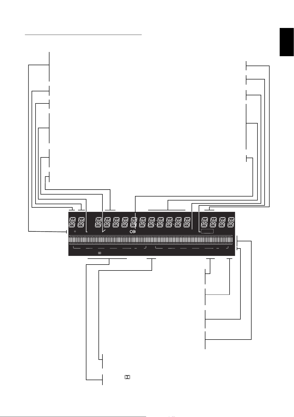
Display
DVD
- DVD Video disc inserted
DVD +RW
- DVD+Rewritable disc inserted
DVD +R
- DVD+Recordable disc inserted
TITLE
- Current DVD title number
TRACK
- Current VCD/CD track number
VCD
- Video CD inserted
CD
- Audio CD inserted
SVCD
- Super Video CD inserted
HQ - SP+ - EP - EP+
- Selected recording mode: High Quality,
Standard Play Plus, Extended Play or Extended
Play Plus
CHAPTER
- DVD chapter number
English
CHANNEL
- Current channel number
RECORD
- Recording in progress
TIMER
- A Timer is programmed or active
TRACK TIME
- Track time in minutes and seconds
TOTAL TIME
- Total playback time in hours,
minutes and seconds
TIME REMAIN
- Total remaining recording time in hours,
minutes and seconds
- Remote Control command received
TITLE TRACK
DVD CDVRW
CHAPTER TOTAL TIME REMAINTRACK
SA
HQ
SP EP+
PCMDTSDIGITALMPEG
MONITOR
MANUAL
TIMER
-30-40 -10-20 0 OVER-30-40 -10-20 0 OVER
STEREO
PM
AM
CHANNEL
RECORD
STEREO
SAP
- The current channel is broadcasting
in stereo
SAP
- A second audio program is available
on the current channel
dB scale
- indicates recording volume when
using manual controls
Disc bar
- Displays disc content, recording level or
formatting progress
MANUAL
- Appears when you manually adjust the
recording level
MPEG - DIGITAL - DTS - PCM
- Active audio format
FUNCTIONAL OVERVIEW 11
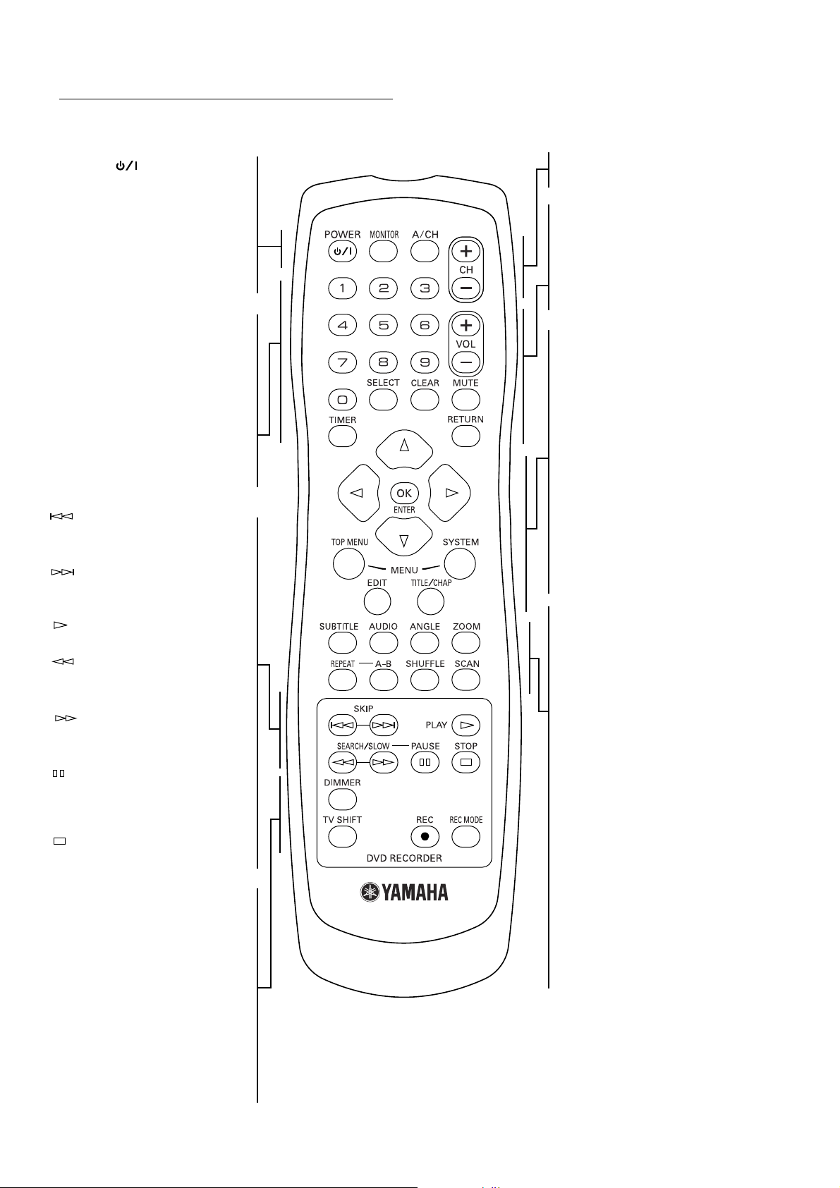
Remote control
POWER ( )
- switches the Recorder On or
to standby mode (off)
MONITOR
- switches between disc mode and
monitor mode
A/CH (Alternate Channel)
- switches to previous TV channel
0-9
- numerical buttons to enter
information or select channels
SELECT
- switches between different values
in a menu
CLEAR
- delete last entry/clear a timer
TIMER
- displays the timer menu
SKIP
- select a previous chapter, track
or title
SKIP
- skip to next chapter, track or
title
PLAY
- begin disc playback
SEARCH/SLOW
- search backward on a disc during
playback
SEARCH/SLOW
- search forward on a disc during
playback
PAUSE
- pause playback or recording,
press repeatedly for step-by-step
disc playback
STOP
- stop playback or recording
DIMMER
- changes the brightness of the
display
TV SHIFT
- press and hold while using other
remote control buttons to work
the TV
0 REC
- direct recording of the currently
selected program channel
CH +/–
- change channel up/down
VOL +/–
- TV volume up/down
MUTE
- TV Mute ON/OFF
RETURN
- go back to previous menu step
wvt u
- move cursor down/up/left/right
ENTER/OK
- acknowledge menu selection
TOP MENU
- displays DVD disc menu or Index
Picture Screen for a DVD+RW
SYSTEM MENU
- displays Recorder system menu bar
EDIT
- displays edit menu for DVD+RW
or DVD+R disc
TITLE/CHAP
- select title
- select chapter
SUBTITLE
- select subtitle language on a DVD
AUDIO
- select audio language on a DVD
ANGLE
- select DVD camera angle on a
DVD
ZOOM
- enlarge video image on a DVD
REPEAT
- repeat chapter, track, title, disc
A-B
- repeat a specific sequence
SHUFFLE
- play tracks in random order
SCAN
- play the first 10 seconds of each
chapter within a title (DVD) or the
first 10 seconds of each track on
disc (VCD/CD) or each Title on a
DVD+RW / DVD+R
REC MODE
- switches recording modes
12 FUNCTIONAL OVERVIEW
Operation
Important notes for operation
You can switch on the DVD Recorder with the
STANDBY/ON button on the front of the Recorder or
POWER (B/I) button on the remote control to
interrupt a function. Keep your DVD Recorder connected
to the power outlet at all times to ensure programmed
recordings can be made.
Notes:
- Never turn the recorder on right after connecting the power
jack to a wall outlet, while the STANDBY indicator lights green.
Wait until the indicator turns red.
- When you switch off the DVD Recorder, the display will briefly
show ‘WAIT.’
Loading discs
Disc types
You will recognize the different types of discs that can be
used in your DVD Recorder by the logo. Depending on
the disc type you can either use it for recording and
playback or playback only. Some discs are not suitable to
be used in the DVD Recorder at all.
The following information summarizes existing disc types
and their DVD Recorder compatibility.
Discs for recording and playing:
DVD+RW
Records and plays. In case of a new blank disc, after the
first recording, some more time (up to two minutes) is
needed by the Recorder to automatically make the disc
compatible with DVD video players.
DVD+R
Records and plays.
English
1 Press / on the front of the Recorder. The disc tray
opens.
2 Lay your chosen disc in the tray, label side up. If the
disc is two side, make sure the side you want to play is
facing up.
Make sure it is sitting properly in the correct recess.
3 Press / to close the tray.
➤ ‘READING’ appears on the Recorder display. If the
disc is pre-recorded or erase-protected, playback will
start automatically.
You can unload a disc by pressing / again or by pressing
and holding 9 for two seconds.
Note:
If ‘Child Lock’ is ‘On’ and the disc inserted is not in the ‘child
safe’ list (not authorized), the PIN code must be entered and/or
the disc has to be authorized. (see ‘Access control’)
Discs for playing only:
DVD-Video
DVD-R (DVD-Recordable)
These play only if they contain DVD-Video.
DVD-RW
Plays only if it is recorded in Video mode and has been
finalized.
49
OPERATION 13
CD Digital Audio
You can play digital audio CDs in conventional style
through a stereo system, using the buttons on the remote
control and/or front panel of the DVD Recorder.
Super Audio CD
Of hybrid SACD discs, the CD layer can play.
(Super) Video CD
Depending on the material on the disc (a movie, video
clips, a drama series, etc.), these discs may have one or
more tracks. Tracks may have one or more indexes as
indicated on the disc case. To make access easy and
convenient, your Recorder lets you move between tracks
and indexes.
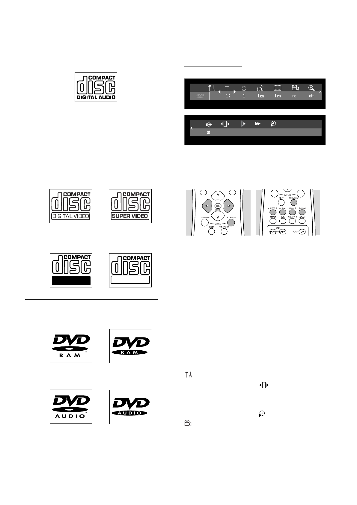
On-screen display information
System menu bar
Access the system menu bar by pressing any of the
following buttons on the remote control: SYSTEM
MENU, TITLE/CHAP, ANGLE, SUBTITLE, AUDIO
and ZOOM.
CD-R (Recordable) / CD-RW (Rewritable)
These play only if it contain Audio CD material.
Recordable
ReWritable
Discs unsuitable for recording or playing:
DVD-RAM
DVD-Audio
Widescreen (16:9) TV sets may show only part of the
system menu bar in certain screen modes. Select a
different screen mode on the TV to see the full menu.
A number of Recorder functions can be controlled via the
system menu bar. You can move between the two parts of
the system menu bar with t (left cursor) and u (right
cursor).
Note:
Certain televisions may not show the entire DRX-1 menu on
the TV screen. If the upper or top portion of the Recorder’s
menu is not displayed properly, this is a TV-related issue and is
not an improper functioning of the DRX-1.
System menu bar icons
Part 1 Part 2
User preferences d Sound
W Current Title/Track Step motion
X Current Chapter/Index H Slow motion
Y Audio language 6 Fast motion
Z Subtitle language Time search
Angle
a Zoom
14 OPERATION
 Loading...