


2002 - 2005
Downloaded from www.ScooterTime.net
MOTORCYCLE
SERVICE MANUAL
Model : YW50P, YW50R, YW50S, YW50T
5PNF81972000
*5PNF81972000*
Downloaded from www.ScooterTime.net
EBO00000
Downloaded from www.ScooterTime.net
YW50BP
SERVICE MANUAL
©2001 by Yamaha Motor Taiwan Co,.Ltd.
First edition, November 2001
All rights reserved.
Any reprinting or unauthorized use
without the written permission of
Yamaha Motor Taiwan Co,.Ltd.
is expressly prohibited.

EB001000
Downloaded from www.ScooterTime.net
NOTICE
This manual was produced bythe Yamaha Motor Company, Ltd. primarily for use byYamaha deal-
ers and their qualified mechanics. It is not possible to include all the knowledge of a mechanic in
one manual. Therefore, anyone who uses this book to perform maintenance and repairs on Yamaha
vehicles should have a basic understanding of mechanics and the techniques to repair these types
of vehicles. Repair and maintenance work attempted by anyone without this knowledge is likely to
render the vehicle unsafe and unfit for use.
Yamaha Motor Company, Ltd. is continually striving to improve all of its models. Modifications
and significant changes in specifications or procedures will be forwarded to all authorized Yamaha
deal-ers and will appear in future editions of this manual where applicable.
NOTE:
Designs and specifications are subject to change without notice.
IMPORTANT MANUAL INFORMATION
Particularly important information is distinguished in this manual by the following.
ZL
~'~,WARNING
CAUTION:
NOTE:
The Safety Alert Symbol means ATTENTION! BECOME ALERT! YOUR
SAFETY IS INVOLVED!
Failure to folIowWARNING instructions could result in severe injury or death
to the scooter operator, a bystander or a person checking or repairing the
scooter.
A CAUTION indicates special precautions that must be taken to avoid dam-
age to the scooter.
A NOTE provides key information to make procedures easier or clearer.
HOW TO USE THIS MANUAL
Downloaded from www.ScooterTime.net
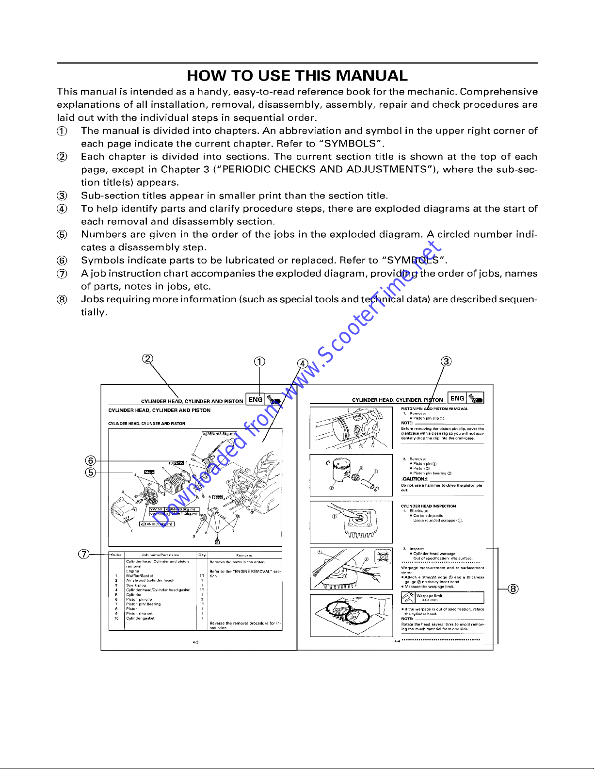
This manual is intended as a handy, easy-to-read reference book for the mechanic. Comprehensive
explanations of all installation, removal, disassembly, assembly, repair and check procedures are
laid out with the individual steps in sequential order.
(~ The manual is divided into chapters. An abbreviation and symbol in the upper right corner of
each page indicate the current chapter. Refer to "SYMBOLS".
(~ Each chapter is divided into sections. The current section title is shown at the top of each
page, except in Chapter 3 ("PERIODIC CHECKS AND ADJUSTMENTS"), where the sub-sec-
tion title(s) appears.
(~ Sub-section titles appear in smaller print than the section title.
(~ To help identify parts and clarify procedure steps, there are exploded diagrams at the start of
each removal and disassembly section.
(~ Numbers are given in the order of the jobs in the exploded diagram. A circled number indi-
cates a disassembly step.
(~ Symbols indicate parts to be lubricated or replaced. Refer to "SYMBOLS".
(~) A job instruction chart accompanies the exploded diagram, providing the order of jobs, names
of parts, notes in jobs, etc.
(~ Jobs requiring more information (such as special tools and technical data) are described sequen-
tially.
®
®
Cvlinder
head.
Cylinder and piston
removal
Engine
1
Muffler/Gasket
2 Air ~hroud (cylTnder head)
3 Spark IJlug
4 Cylinder head/Cylinder head gasket
Cylinder
6 Piston pin clip
7
Piston pin/Bearing
8
Piston
9 Piston
ring set
10
CyITnder gasket
Q'ty Rurllark~
Remove the pa~s En the order
Refer to the
1/1
1/1
1
1
1
2
1
1
1
"ENGINE REMOVAL"
tion
Reverse the removal procedure for in
stallatien.
sec-
CYLINDEB HEAD" CYF~:N::R: P~~
1.
Remove:
• san nc
NoTE PI t pT IIp~)
' crankcase with a
Begore removing tha piston pin celt,, cover the
Donot use a hammer to drive the piston pin
out_
CYUNDER HEAD INSPECTION
Warpage measurement and re surfacement
• Attach a
•
• If the warpage is out of
NOTE:
Rotate the head severaT tTres to avoid remov-
ing too much moteriol from one side.
4-4 ..................................... --
clean rag so you will not acci
Z. Ro,,,ovo:
•
Piston pTn
1~
• Piston ®
• Piston pin bearing ~
GA~ON~
~. Elhxlin~te:
• Carbon deposits
Use a rounded ~crapper
•
Cylinder head
war~3age
Out of specification
gauge (~ on the cylinder head.
Measure the warpage
the cylinder head.
>Re 8ur'0ce.
=traight edge ~ and a thickness
limit.
specification, reface
@
I
Q ®
Downloaded from www.ScooterTime.net
GEN
INFO
®
®
INSP
®
®
CARB
®
ELEC
~=]
SPEC
ENG
~)~
CHAS (~®
TRBL w.~
SHTG •
EAS00009
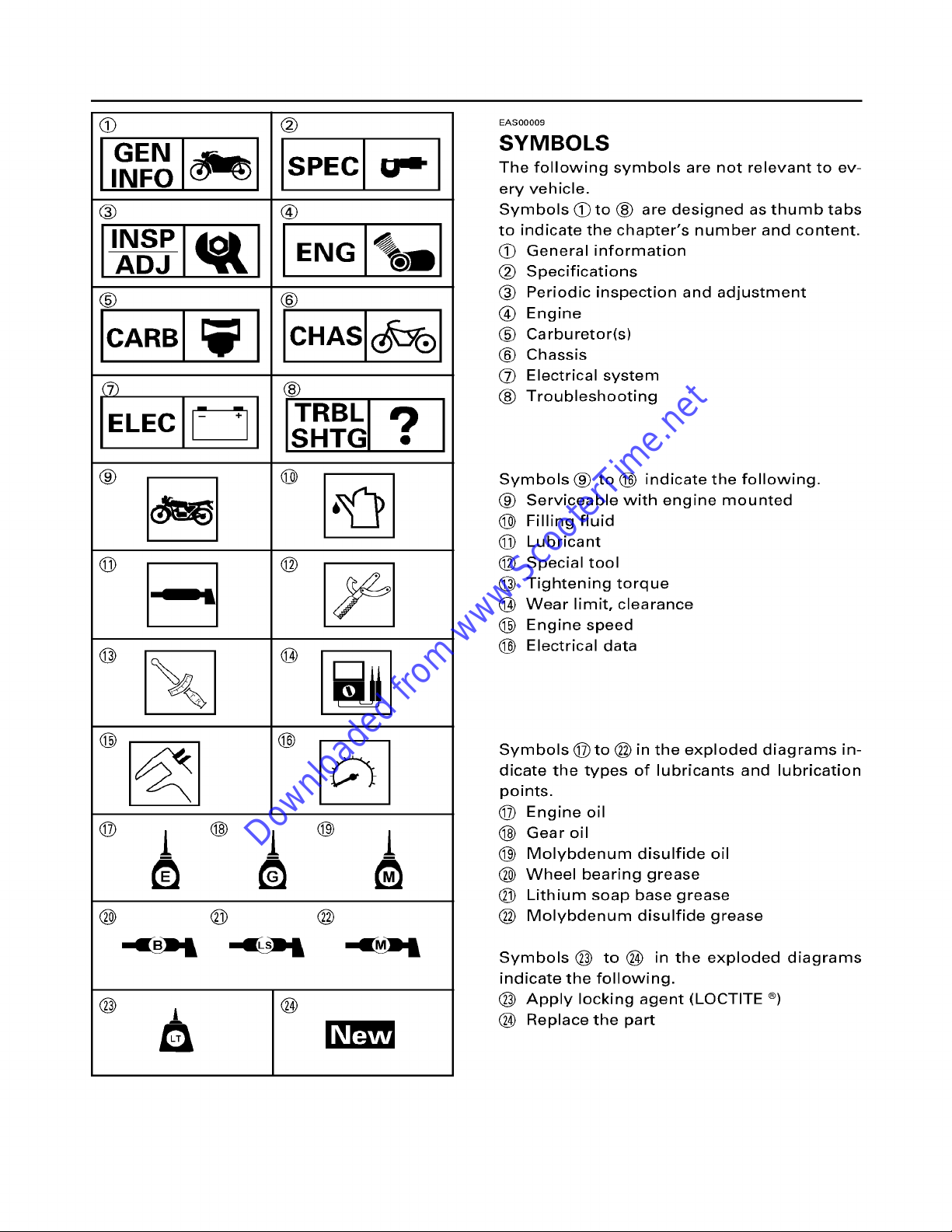
SYMBOLS
The following symbols are not relevant to ev-
ery vehicle.
Symbols (~to (~ are designed as thumb tabs
to indicate the chapter's number and content.
(~ General information
(~ Specifications
(~ Periodic inspection and adjustment
Engine
(~) Carburetor(s)
(~ Chassis
(~ Electrical system
(~ Troubleshooting
®
@
©
®
-n~
@
@
® i i 1
® ® @
@
@
Symbols (~ to (~)
®
Serviceable with engine mounted
@
Filling fluid
@
Lubricant
@
Special tool
@
Tightening torque
@
Wear limit, clearance
@
Engine speed
@
Electrical data
Symbols @to @ in the exploded diagrams in-
dicate the types of lubricants and lubrication
points.
(~ Engine oil
@ Gear oil
(~) Molybdenum disulfide oil
(~ Wheel bearing grease
(~ Lithium soap base grease
(~) Molybdenum disulfide grease
indicate the following.
Symbols@ to @ in the exploded diagrams
indicate the following.
@ @
(~ Apply locking agent (LOCTITE ®)
(~ Replace the part
I~lew
INDEX
Downloaded from www.ScooterTime.net
GENERAL INFORMATION
SPECIFICATIONS
PERIODIC INSPECTION AND
ADJUSTMENT
ENGINE OVERHAUL
1
g,=.
CARBURETION
CHASSIS
ELECTRICAL
TROUBLESHOOTING
~o
CHAPTER 1.
Downloaded from www.ScooterTime.net
GENERAL INFORMATION
SCOOTER INDENTIFICATION
VEHICLE IDENTIFICATION NUMBER ........................................................................................... 1-1
MODEL CODE ................................................................................................................................ 1-1
IMPORTANT INFORMATION
PREPARATION FOR REMOVAL AND DISASSEMBLY ................................................................ 1-2
REPLACEMENT PARTS ................................................................................................................. 1-2
GASKETS, OIL SEALS AND O-RINGS .......................................................................................... 1-2
LOCK WASHERS/PLATES AND COTTER PINS ........................................................................... 1-2
BEARINGS AND OIL SEALS ......................................................................................................... 1-3
CIRCLIPS ........................................................................................................................................ 1-3
CHECKING OF CONNECTIONS
HOW TO USE
CONVERSION TABLE .................................................................................................................... 1-5
SPECIAL TOOLS
THE CONVERSION TABLE
................................................................................................................................ 1-6
........................................................................................................... 1-1
............................................................................................................ 1-2
........................................................................................................ 1-4
....................................................................................... 1-5

CHAPTER 2.
Downloaded from www.ScooterTime.net
SPECIFICATIONS
GENERAL SPECIFICATION ............................................................................................................... 2-1
MAINTENANCE SPECIFICATION
ENGINE .......................................................................................................................................... 2-4
TIGHTENING TORQUES ............................................................................................................... 2-6
ENGINE .......................................................................................................................................... 2-6
MAINTENANCE SPECIFICATION
CHASSIS ........................................................................................................................................ 2-7
TIGHTENING TORQUES ............................................................................................................... 2-8
CHASSIS ........................................................................................................................................ 2-8
MAINTENANCE SPECIFICATION ..................................................................................................... 2-9
ELECTRICAL ................................................................................................................................... 2-9
GENERAL TORQUE SPECIFICATIONS
LUBRICATION POINTS AND LUBRICATION TYPE
ENGINE ........................................................................................................................................ 2-12
CHASSIS ...................................................................................................................................... 2-13
CABLE ROUTING
............................................................................................................................. 2-14
..................................................................................................... 2-4
..................................................................................................... 2-7
........................................................................................... 2-1 1
....................................................................... 2-12

CHAPTER 3.
Downloaded from www.ScooterTime.net
PERIODIC INSPECTION AND ADJUSTMENTS
INTRODUCTION ................................................................................................................................ 3-1
PERIODIC MAINTENANCE/LUBRICATION INTERVALS ................................................................ 3-1
COVER AND PANEL
SIDECOVER AND SEAT ................................................................................................................ 3-3
LOWER COWLING, UPPER COVER, LEG SHIELD 1, 2 AND FOOTREST BOARD ..................... 3-4
HANDLEBAR COVER(FRONT AND REAR) ................................................................................... 3-5
ENGINE
IDLE SPEED ADJUSTMENT .......................................................................................................... 3-6
THROTTLE CABLE FREE ADJUSTMENT ..................................................................................... 3-7
AUTOLUBE PUMP AIR BLEEDING ............................................................................................... 3-8
SPARK PLUG INSPECTION ........................................................................................................... 3-9
ENGINE OIL LEVEL INSPECTION ............................................................................................... 3-10
TRANSMISSION OIL REPLACEMENT ........................................................................................ 3-11
AIR FILTER ELEMENT CLEANING .............................................................................................. 3-12
V-BELT INSPECTION ................................................................................................................... 3-14
CHASSIS
FRONT BRAKE LEVER FREE PLAY CHECK ................................................................................ 3-15
REAR BRAKE LEVER FREE PLAY CHECK ................................................................................... 3-15
BRAKE PAD INSPECTION ........................................................................................................... 3-15
BRAKE SHOE INSPECTION ........................................................................................................ 3-16
BRAKE FLUID LEVEL INSPECTION ............................................................................................ 3-16
AIR BLEEDING (HYDRAULIC BRAKE SYSTEM) ........................................................................ 3-17
STEERING ADJUSTMENT .......................................................................................................... 3-18
TIRE INSPECTION ........................................................................................................................ 3-19
WHEEL INSPECTION ................................................................................................................... 3-22
FRONT FORK INSPECTION ......................................................................................................... 3-22
REAR SHOCK ABSORBER INSPECTION .................................................................................... 3-22
SEAT LOCK CABLE ADJUSTMENT ........................................................................................... 3-22
CABLE CHECKING AND LUBRICATING ..................................................................................... 3-23
LEVERS LUBRICATING ............................................................................................................... 3-23
CENTERSTAND LUBRICATING .................................................................................................. 3-23
ELECTRICAL
BATTERY INSPECTION ............................................................................................................... 3-24
FUSE INSPECTION ...................................................................................................................... 3-29
HEADLIGHT BEAM ADJUSTMENT ............................................................................................ 3-30
HEADLIGHT BULB REPLACEMENT ............................................................................................ 3-30
TURN SIGNAL AND TAILLIGHT BULB REPLACEMENT ........................................................... 3-31
TAILLIGHT BULB REPLACEMENT .............................................................................................. 3-32
LICENSE LIGHT BULB REPLACEMENT ...................................................................................... 3-32
.............................................................................................................................................. 3-6
.......................................................................................................................................... 3-15
..................................................................................................................................... 3-24
.......................................................................................................................... 3-3
CHAPTER 4.
Downloaded from www.ScooterTime.net
ENGINE
ENGINE OVERHAUL
WlREHARNESS AND CABLES ...................................................................................................... 4-1
CYLINDER HEAD, CYLINDER AND PISTON
CYLINDER HEAD, CYLINDER AND PISTON ................................................................................ 4-3
PISTON PIN AND PISTON REMOVAL .......................................................................................... 4-4
CYLINDER HEAD INSPECTION ..................................................................................................... 4-4
CYLINDER AND PISTON INSPECTION ........................................................................................ 4-5
PISTON RINGS INSPECTION ........................................................................................................ 4-7
PISTON PIN AND PISTON PIN BEARING .................................................................................... 4-7
PISTON PIN AND PISTON INSTALLATION ................................................................................. 4-8
CYLINDER AND CYLINDER HEAD ................................................................................................ 4-9
V-BELT, CLUTCH AND SECONDARY/PRIMARY SHEAVE
KICK STARTER AND CRANKCASE COVER(LEFT) ..................................................................... 4-1 1
KICK STARTER ............................................................................................................................. 4-12
KICK STARTER INSTALLATION ................................................................................................. 4-13
V-BELT, CLUTCH AND SECONDARY/PRIMARY SHEAVE ........................................................ 4-14
SECONDARY SHEAVE ................................................................................................................ 4-15
PRIMARY SHEAVE REMOVAL .................................................................................................... 4-16
SECONDARY SHEAVE REMOVAL .............................................................................................. 4-16
CLUTCH INSPECTION ................................................................................................................. 4-17
V-BELT INSPECTION ................................................................................................................... 4-18
PRIMARY SHEAVE INSPECTION ................................................................................................ 4-19
SECONDARY SHEAVE ................................................................................................................ 4-20
SECONDARY SHEAVE INSTALLATION ..................................................................................... 4-21
PRIMARY SHEAVE ...................................................................................................................... 4-22
STARTER CLUTCH AND STARTER MOTOR
STARTER CLUTCH AND STARTER MOTOR .............................................................................. 4-24
STARTER CLUTCH AND GEARS INSPECTION ......................................................................... 4-26
C.D.I. MAGNET ................................................................................................................................ 4-27
C.D.I. MAGNETO ......................................................................................................................... 4-27
C.D.I. MAGNETO REMOVAL ....................................................................................................... 4-28
C.D.I. MAGNETO INSTALLATION .............................................................................................. 4-28
AUTOLUBE PUMP
AUTOLUBE PUMP ....................................................................................................................... 4-29
AUTOLUBE PUMP INSTALLATION ........................................................................................... 4-30
TRANSMISSION
TRANSMISSION .......................................................................................................................... 4-31
CRANKCASE AND REED VALVE
CRANKCASE AND REED VALVE ................................................................................................ 4-33
CRANKCASE(RIGHT) REMOVAL ................................................................................................ 4-35
CHECKING THE CRANKCASE .................................................................................................... 4-35
CHECKING THE BEARINGS AND OIL SEALS ............................................................................ 4-35
REED VALVE INSPECTION ......................................................................................................... 4-36
CRANKCASE (RIGHT) INSTALLATION ...................................................................................... 4-36
CRANKSHAFT
CRANKSHAFT .............................................................................................................................. 4-38
CRANKSHAFT REMOVAL ........................................................................................................... 4-39
CRANKSHAFT INSPECTION ....................................................................................................... 4-39
CRANKSHAFT INSTALLATION ................................................................................................... 4-40
.................................................................................................................................. 4-38
......................................................................................................................... 4-1
.................................................................................... 4-3
........................................................... 4-1
................................................................................. 4-24
........................................................................................................................... 4-29
.............................................................................................................................. 4-31
.................................................................................................... 4-33
1
CHAPTER 5
Downloaded from www.ScooterTime.net
CARBURETION
CARBURETION .................................................................................................................................. 5-1
CARBURETOR ................................................................................................................................ 5-1
CABURETOR DISASSEMBLY ....................................................................................................... 5-2
CABURETOR INSPECTION ........................................................................................................... 5-3
CARBURETOR ASSEMBLY ........................................................................................................... 5-5
FUEL LEVEL ADJUSTMENT ......................................................................................................... 5-6
AUTO CHOKE INSPECTION .......................................................................................................... 5-7
FUEL COCK INSPECTION ............................................................................................................. 5-8
CHAPTER 6
Downloaded from www.ScooterTime.net
CHASSIS
FRONT WHEEL AND BRAKE DISC
FRONT WHEEL AND BRAKE DISC ............................................................................................... 6-1
FRONT WHEEL DISASSEMBLY .................................................................................................... 6-2
FRONT WHEEL DISASSEMBLY .................................................................................................... 6-3
FRONT WHEEL INSPECTION ........................................................................................................ 6-3
BRAKE DISC INSPECTION ............................................................................................................ 6-4
FRONT WHEEL ASSEMBLY .......................................................................................................... 6-4
FRONT WHEEL INSTALLATION ................................................................................................... 6-5
WHEEL STATIC BALANCE ADJUSTMENT .................................................................................. 6-6
................................................................................................... 6-1
FRONT BRAKE ................................................................................................................................... 6-8
BRAKE PAD .................................................................................................................................... 6-8
BRAKE PAD REPLACEMENT ........................................................................................................ 6-9
MASTER CYLINDER
MASTER CYLINDER DISASSEMBLY
MASTER CYLINDER INSPECTION .............................................................................................. 6-14
MASTER CYLINDER ASSEMBLY ................................................................................................ 6-14
MASTER CYLINDER INSTALLATION ......................................................................................... 6-15
CALIPER
........................................................................................................................................... 6-17
........................................................................................................................ 6-12
............................................................................................. 6-13
CALIPER DISASSEMBLY ................................................................................................................. 6-18
BRAKE CALIPER DISASSEMBLY ................................................................................................ 6-19
CALIPER INSPECTION ................................................................................................................. 6-19
BRAKE CALIPER ASSEMBLY ...................................................................................................... 6-20
BRAKE CALIPER INSTALLATION ............................................................................................... 6-20
REAR WHEEL AND REAR BRAKE
REAR WHEEL ............................................................................................................................... 6-21
REAR BRAKE ................................................................................................................................ 6-22
REAR WHEEL INSPECTION ........................................................................................................ 6-23
REAR BRAKE INSPECTION ......................................................................................................... 6-23
REAR BRAKE INSTALLATION .................................................................................................... 6-24
HANDLEBAR
HANDLEBAR ................................................................................................................................ 6-25
HAN DLE BAR I NSTALLATIO N ..................................................................................................... 6-27
STEERING
STEERING .................................................................................................................................... 6-29
STEERING REMOVAL ................................................................................................................. 6-30
STEERING INSPCTION ................................................................................................................ 6-31
STEERING INSTALLATION ......................................................................................................... 6-31
FRONT FORK
FRONT FORK ............................................................................................................................... 6-34
FRONT FORK DISASSEMBLY ..................................................................................................... 6-35
FRONT FORK REMOVAL ............................................................................................................. 6-36
FRONT FORK DISASSEMBLY ..................................................................................................... 6-36
FRONT FORK INSPECTION ......................................................................................................... 6-37
FRONT FORK ASSEMBLY ........................................................................................................... 6-37
FRONT FORK INSTALLATION .................................................................................................... 6-39
.................................................................................................................................... 6-25
........................................................................................................................................ 6-29
................................................................................................................................... 6-34
.................................................................................................. 6-21
CHAPTER 7
Downloaded from www.ScooterTime.net
ELECTRICAL
ELECTRICAL COMPONENTS
ELECTRICAL COMPONENTS ........................................................................................................ 7-1
CIRCUIT DIAGRAM ........................................................................................................................ 7-2
CHECKING SWITCHES
CHECKING STEPS ......................................................................................................................... 7-4
SWITCH CONNECTION AS SHOWN IN THIS MANUAL ............................................................. 7-4
............................................................................................................ 7-1
...................................................................................................................... 7-4
SWITCH POSITION AND TERMINAL CONNECTION ...................................................................... 7-5
CHECKING THE BLUBS AND BULB SOCKETS ............................................................................... 7-5
CHECKING THE BULBS AND BULB SOCKETS ........................................................................... 7-6
TYPES OF BULBS .......................................................................................................................... 7-6
CHECKING THE CONDITION OF THE BULBS .............................................................................. 7-7
CHECKING THE CONDITION OF THE BULB SOCKETS .............................................................. 7-8
IGNITION SYSTEM
CIRCUIT DIAGRAM ........................................................................................................................ 7-9
TROUBLESHOOTING .................................................................................................................. 7-10
CHARGING SYSTEM
CIRCUIT DIAGRAM ...................................................................................................................... 7-14
TROUBLESHOOTING .................................................................................................................. 7-15
ELECTRIC STARTING SYSTEM
CIRCUIT DIAGRAM ...................................................................................................................... 7-18
TROUBLESHOOTING .................................................................................................................. 7-19
STARTER MOTOR ....................................................................................................................... 7-22
STARTER MOTOR DISASSEMBLY ............................................................................................. 7-23
INSPECTION AND REPAIR .......................................................................................................... 7-24
LIGHTING SYSTEM
CIRCUIT DIAGRAM ...................................................................................................................... 7-26
TROUBLESHOOTING .................................................................................................................. 7-27
LIGHTING SYSTEM CHECK ........................................................................................................ 7-29
SIGNAL SYSTEM
CIRCUIT DIAGRAM ...................................................................................................................... 7-33
TROUBLESHOOTING .................................................................................................................. 7-34
SIGNAL SYSTEM CHECK ............................................................................................................ 7-36
AUTO CHOKE SYSTEM
CIRCUIT DIAGRAM ...................................................................................................................... 7-42
TROUBLESHOOTING .................................................................................................................. 7-43
............................................................................................................................ 7-9
....................................................................................................................... 7-14
...................................................................................................... 7-18
......................................................................................................................... 7-26
............................................................................................................................. 7-33
.................................................................................................................. 7-42
CHAPTER 8
Downloaded from www.ScooterTime.net
TROUBLESHOOTING
STARTING FAILURE/HARD STARTING
FUEL SYSTEM ............................................................................................................................... 8-1
IGNITION SYSTEM ........................................................................................................................ 8-2
COMPRESSION SYSTEM ............................................................................................................. 8-2
POOR IDLE SPEED PERFORMANCE
POOR IDLE SPEED PERFORMANCE ............................................................................................ 8-3
POOR MIDIUM AND HIGH SPEED PERFORMANCE
POOR MIDIUM AND HIGH SPEED PERFORMANCE ................................................................... 8-3
FULTY AUTOMATIC(V-BELT TYPE)
SCOOTER DOES NOT MOVE WHILE ENGINE IS OPERATING .................................................. 8-4
CLUTCH OUT FAILURE ................................................................................................................. 8-4
POOR STANDING START(LOW CLIMBING ABILITY) ................................................................. 8-4
POOR ACCELERATION(POOR HIGH SPEED) .............................................................................. 8-4
........................................................................................... 8-1
................................................................................................ 8-3
....................................................................... 8-3
................................................................................................. 8-4
OVER HEAT ........................................................................................................................................ 8-5
OVERHEAT ..................................................................................................................................... 8-5
POOR SPEED ..................................................................................................................................... 8-5
POOR SPEED ................................................................................................................................. 8-5
IMPROPER KICKING
SLIPPING ........................................................................................................................................ 8-6
HARD KICKING .............................................................................................................................. 8-6
KICK CRANK NOT RETURNING ................................................................................................... 8-6
FAULTY BRAKE
POOR BRAKING EFFECT ............................................................................................................... 8-7
MALFUNCTION ............................................................................................................................. 8-7
INSTABLE HANDLING
INSTABLE HANDLING .................................................................................................................. 8-8
FAULTY SIGNAL AND LIGHTING
HEADLIGHT DARK ......................................................................................................................... 8-9
BULB BURNT OUT ........................................................................................................................ 8-9
FLASHER DOES NOT BLINK ......................................................................................................... 8-9
FLASHER KEEPS ON ..................................................................................................................... 8-9
FLASHER BLINKS SLOWER ........................................................................................................ 8-10
FLASHER BLINKS QUICKER ....................................................................................................... 8-10
HORN DOES NOT SOUND ......................................................................................................... 8-10
.......................................................................................................................... 8-6
................................................................................................................................. 8-7
...................................................................................................................... 8-8
SYSTEM .................................................................................... 8-9
SCOOTER INDENTIFICATION
Downloaded from www.ScooterTime.net
I GEN
f
EAS00015
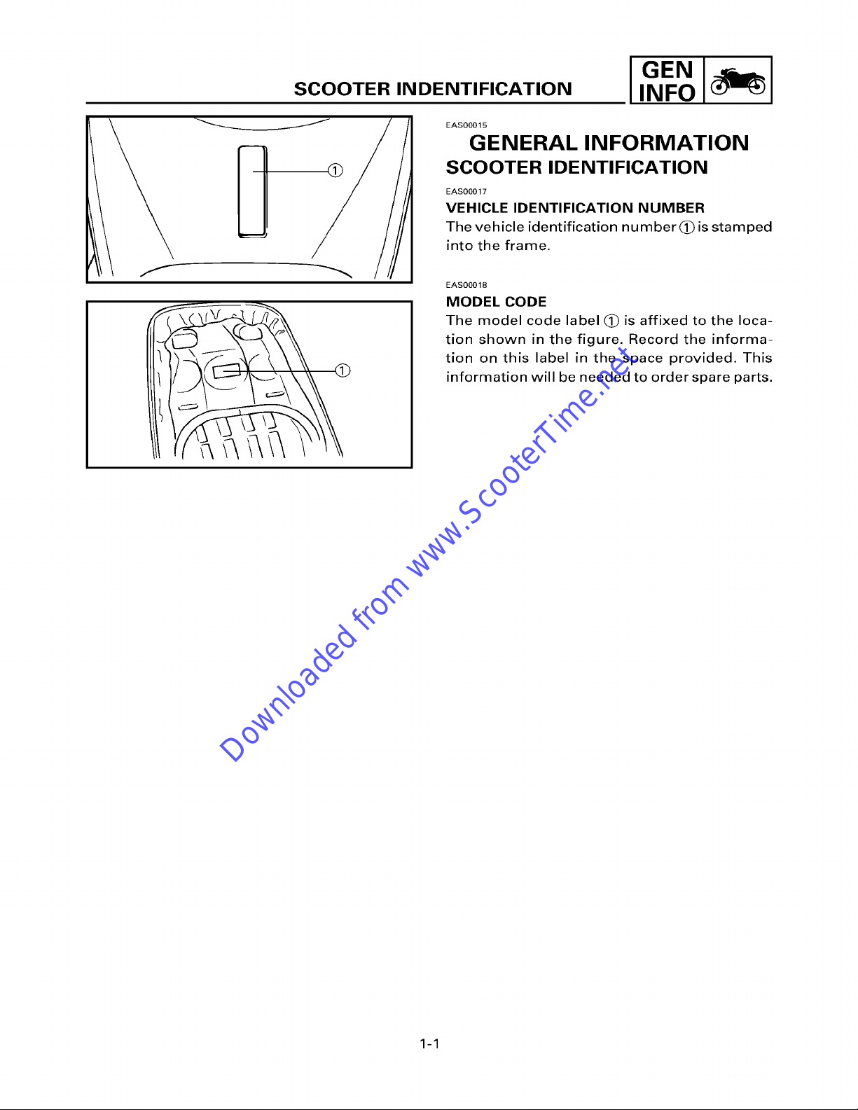
GENERAL INFORMATION
SCOOTER IDENTIFICATION
EAS00017
VEHICLE IDENTIFICATION NUMBER
The vehicle identification number (~) is stamped
into the frame.
f
EAS00018
MODEL CODE
The model code label ~) is affixed to the loca-
tion shown in the figure. Record the informa-
tion on this label in the space provided. This
information will be needed to order spare parts.
1-1
IMPORTANT INFORMATION
Downloaded from www.ScooterTime.net
EAS00020
IMPORTANT INFORMATION
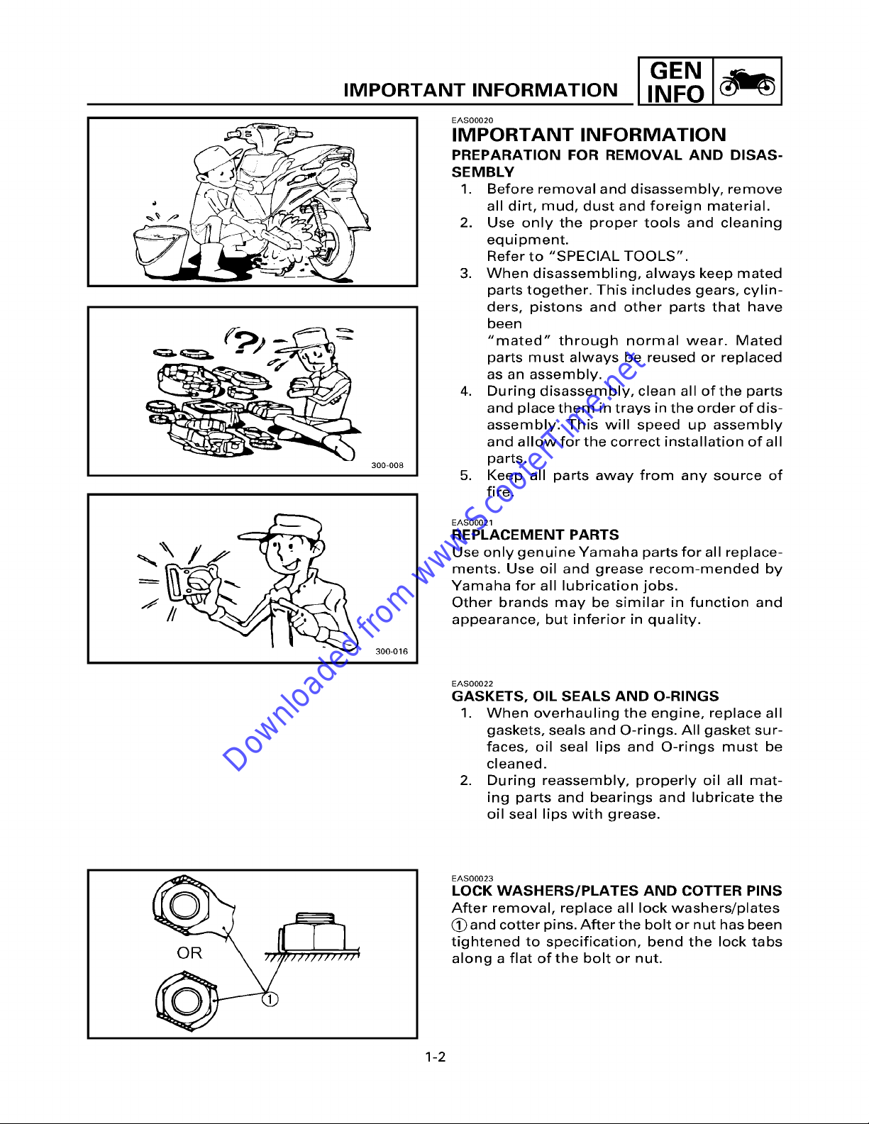
PREPARATION FOR REMOVAL AND DISAS-
SEMBLY
1. Before removal and disassembly, remove
all dirt, mud, dust and foreign material.
2. Use only the proper tools and cleaning
equipment.
Refer to "SPECIAL TOOLS".
3. When disassembling, always keep mated
parts together. This includes gears, cylin-
ders, pistons and other parts that have
been
"mated" through normal wear. Mated
parts must always be reused or replaced
as an assembly.
4. During disassembly, clean all ofthe parts
and place them in trays in the order of dis-
assembly. This will speed up assembly
and allow for the correct installation of all
300-008
parts.
5. Keep all parts away from any source of
fire.
I GEN
300-016
EAS00021
REPLACEMENT PARTS
Use only genuine Yamaha parts for all replace-
ments. Use oil and grease recom-mended by
Yamaha for all lubrication jobs.
Other brands may be similar in function and
appearance, but inferior in quality.
EAS00022
GASKETS, OIL SEALS AND O-RINGS
1. When overhauling the engine, replace all
gaskets, seals and O-rings. All gasket sur-
faces, oil seal lips and O-rings must be
cleaned.
2. During reassembly, properly oil all mat-
ing parts and bearings and lubricate the
oil seal lips with grease.
EAS00023
LOCK WASHERS/PLATES AND COTTER PINS
After removal, replace all lock washers/plates
~)and cotter pins. After the bolt or nut has been
tightened to specification, bend the lock tabs
along a flat ofthe bolt or nut.
1-2
IMPORTANT INFORMATION
Downloaded from www.ScooterTime.net
~\\\\\\\\~1
I GEN
,NFOI I
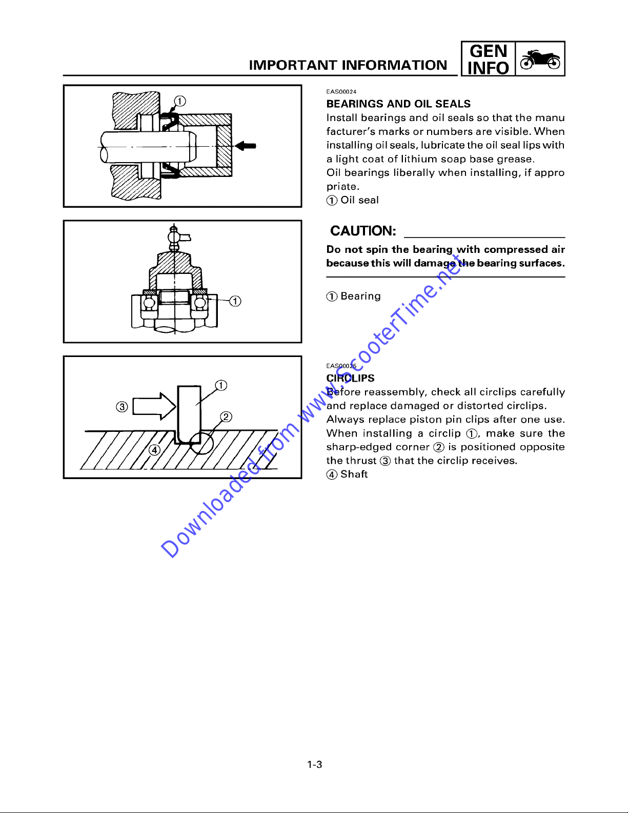
EAS00024
BEARINGS AND OIL SEALS
Install bearings and oil seals so that the manu
facturer's marks or numbers are visible. When
installing oil seals, lubricate the oil seal lipswith
a light coat of lithium soap base grease.
Oil bearings liberally when installing, if appro
priate.
~) Oil seal
CAUTION:
Do not spin the bearing with compressed air
because this will damage the bearing surfaces.
(~ Bearing
EAS00025
CIRCLIPS
Before reassembly, check all circlips carefully
and replace damaged or distorted circlips,
Always replace piston pin clips after one use.
When installing a circlip (~), make sure the
sharp-edged corner (~) is positioned opposite
the thrust ~ that the circlip receives.
(~ Shaft
1-3
IMPORTANT INFORMATION
Downloaded from www.ScooterTime.net
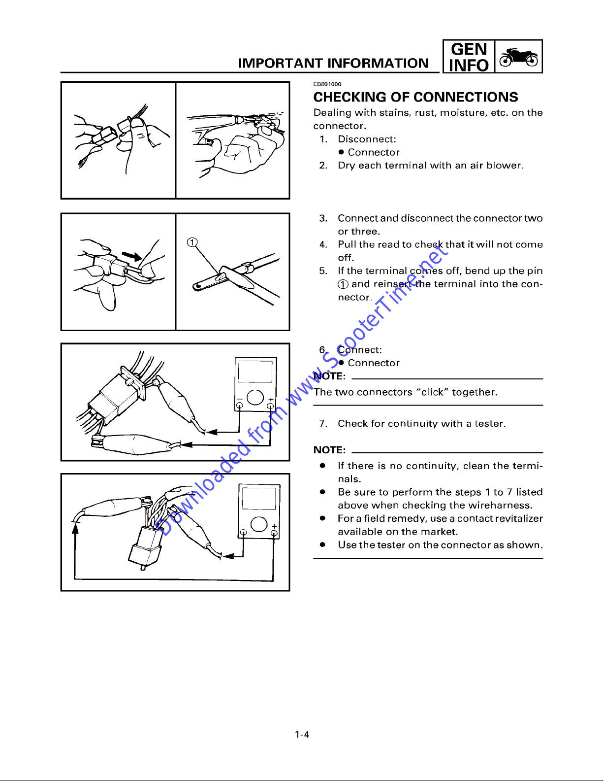
EB801000
CHECKING OF CONNECTIONS
Dealing with stains, rust, moisture, etc. on the
connector.
1. Disconnect:
• Connector
2. Dry each terminal with an air blower.
3. Connect and disconnect the connector two
or three.
4. Pull the read to checkthat it will not come
off.
5. If the terminal comes off, bend up the pin
(~ and reinsert the terminal into the con-
Rector.
I GEN
6. Connect:
• Connector
NOTE:
The two connectors "click" together.
7. Check for continuity with a tester.
NOTE:
• If there is no continuity, clean the termi-
nals.
• Be sure to perform the steps 1 to 7 listed
above when checking the wireharness.
• For a field remedy, use a contact revitalizer
available on the market.
• Use the tester on the connector as shown.
1-4

HOW TO USE THE CONVERSION TABLE
Downloaded from www.ScooterTime.net
EB201000
HOW TO USE THE CONVERSION TABLE
All specification data in this manual are listed in SI and METRIC UNITS.
Use this table to convert METRIC unit data to IMPERIAL unit data.
Ex.
METRIC MULTIPLIER IMP
** mm x 0.03937 = ** in
2 mm x 0.03937 = 0.083 in
CONVERSION TABLE
METRIC TO IMP
Known Multiplier Result
m.kg 7.233 ft.lb
Torque m.kg 86.794 in.lb
cm.kg 0.0723 ft.lb
cm.kg 0.8679 in.lb
Weight kg 2.205 Ib
g 0.03527 oz
Distance
km/h
km
m
m
ca
mm
0.6214
0.6214
3.281
1.094
0.3937
0.03937
mph
mi
ft
yd
in
in
I GEN
Volume/
Capacity
Miscellaneous
cc(cm 3)
cc(cm 3)
lit(liter)
lit(liter)
kg/mm
kg/cm 2
Centigrade
0.03527
0.06102
0.8799
0.2199
55.997
14.2234
9/5(°C)+32
oz (IMP liq.)
cu.in
qt(IMP liq.)
gal(IMP liq.)
Ib/in
psi(Ib/in 2)
Fahrenheit (°F)
1-5

SPECIAL TOOLS I GEN
Downloaded from www.ScooterTime.net
EEl02000
SPECIAL TOOLS
The following special tools are necessary for complete and accurate tune-up and assembly. Use
onlythe appropriate special tools; this Will help prevent damage caused bythe use of inappropri-
ate tools or improvised techniques.
When placing an order, refer to the list provided below to avoid any mistakes.
Tool No. Tool name / Function Illustration
YU-01235
YS-28891
YU -90050
-90062
YU-01189
YU-01135-A
YM-33299
Rotor holding tool
This tool is used to hold the generator ro-
torwhen removing or installing the genera-
tor rotor bolt.
Clutch spring holder
This tool is used to disassembly and assem-
bly the secondary pulley.
Crankshaft Installation set (~
Adapter (~)
These tools are used to install the crank-
shaft.
Flywheel puller
This tool is used for removing the rotor.
Crankcase Separating tool
This tool is used to remove the crankshaft
or separate the crankcase.
Oil seal guide
This tool is used for protecting the oil seal
lip when installing the secondary sliding
sheave.
u
0
YU-33975
YU-01701
YU-8036-A
Steering nut wrench
This tool is used to loosen or tighten the
steering stem ring nut.
Sheave holder
This tool is used to hold the clutch hous-
ing when removing or installing the clutch
housing nut.
Inductive tachometer
This tool is used to check engine speed.
1-6
SPECIAL TOOLS I GEN
Downloaded from www.ScooterTime.net
,.,o1 1
Tool No.
YU-03112
YM-1409
YM-1410
YM-34487
ACC-1100-15-01
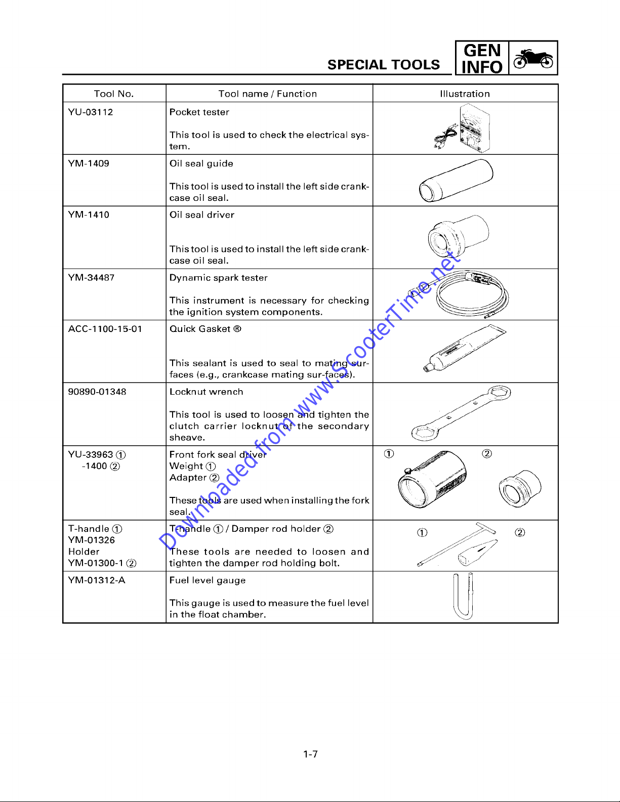
Tool name / Function
Pocket tester
This tool is used to checkthe electrical sys-
tem.
Oil seal guide
This tool is used to install the left side crank-
case oil seal.
Oil seal driver
This tool is used to install the left side crank-
case oil seal.
Dynamic spark tester
This instrument is necessary for checking
the ignition system components.
Quick Gasket ®
This sealant is used to seal to mating sur-
faces (e.g., crankcase mating sur-faces).
I llustratio n
90890-01348
YU-33963
-1400
T-handle (~
YM-01326
Holder
YM-01300-1 (~
YM-01312-A
Lockn ut wrench
This tool is used to loosen and tighten the
clutch carrier Iocknut of the secondary
sheave.
Front fork seal driver
Weight (~
Adapter Q2~
These tools are used when installing the fork
seal.
T-handle (~)/Damper rod holder (~
These tools are needed to loosen and
tighten the damper rod holding bolt.
Fuel level gauge
This gauge is used to nleasure the fuel level
in the float chamber.
®
dJ / ~//
1-7
GENERAL SPECIFICATION
Downloaded from www.ScooterTime.net
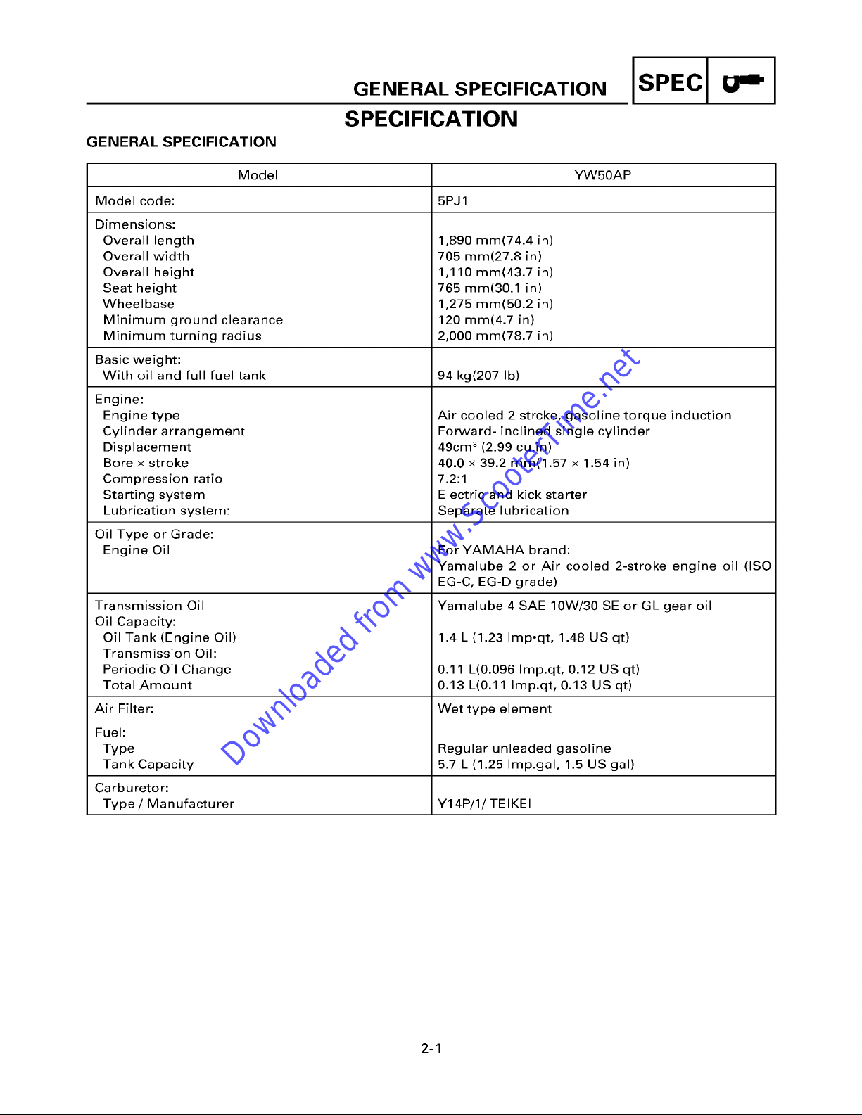
SPECIFICATION
GENERAL SPECIFICATION
Model YW50AP
Model code: 5P J1
Dimensions:
Overall length
Overall width
Overall height
Seat height
Wheelbase
Minimum ground clearance
Minimum turning radius
Basic weight:
With oil and full fuel tank 94 kg(207 Ib)
Engine:
Engine type
Cylinder arrangement
Displacement
Bore x stroke
Compression ratio
Starting system
Lubrication system:
Oil Type or Grade:
Engine Oil
1,890 mm(74.4 in)
705 mm(27.8 in)
1,110 mm(43.7 in)
765 mm(30.1 in)
1,275 mm(50.2 in)
120 mm(4.7 in)
2,000 mm(78.7 in)
Air cooled 2 strcke, gasoline torque induction
Forward- inclined single cylinder
49cm 3 (2.99 cu.in)
40.0 x 39.2 mm(1.57 x 1.54 in)
7.2:1
Electric and kick starter
Separate lubrication
For YAMAHA brand:
Yamalube 2 or Air cooled 2-stroke engine oil (ISO
EG-C, EG-D grade)
IsPEcl.-I
Transmission Oil
Oil Capacity:
Oil Tank (Engine Oil)
Transmission Oil:
Periodic Oil Change
Total Amount
Air Filter: Wet type element
Fuel:
Type Regular unleaded gasoline
Tank Capacity 5.7 L (1.25 Imp.gal, 1.5 US gal)
Carburetor:
Type / Manufacturer Y14P/1/TEIKEI
Yamalube 4 SAE 10W/30 SE or GL gear oil
1.4 L (1.23 Imp°qt, 1.48 US qt)
0.11 L(0.096 Imp.qt, 0.12 US qt)
0.13 L(0.11 Imp.qt, 0.13 US qt)
2-1
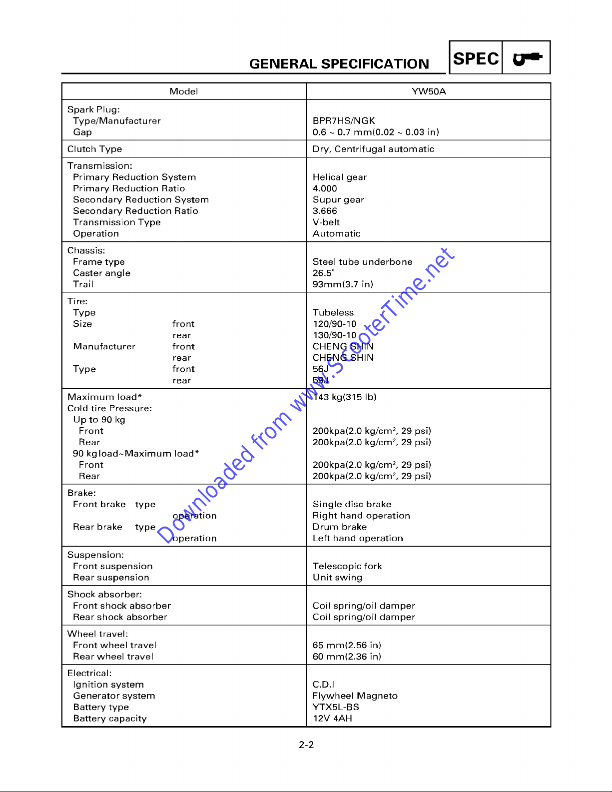
GENERAL SPECIFICATION
Downloaded from www.ScooterTime.net
Model YW50A
Spark Plug:
Type/Manufacturer BPRTHS/NGK
Gap 0.6 ~ 0.7 mm(0.02 ~ 0.03 in)
Clutch Type Dry, Centrifugal automatic
Transmission:
Primary Reduction System
Primary Reduction Ratio
Secondary Reduction System
Secondary Reduction Ratio
Transmission Type
Operation
Chassis:
Frame type
Caster angle
Trail
Tire:
Type
Size front
rear
Manufacturer front
rear
Type front
rear
Maximum load*
Cold tire Pressure:
Up to 90 kg
Front
Rear
90 kg load~Maximum load*
Front
Rear
Brake:
Front brake
Rear brake
Suspension:
Front suspension
Rear suspension
type
operation
type
operation
Helical gear
4.000
Supur gear
3.666
V-belt
Automatic
Steel tube underbone
26.5 °
93mm(3.7 in)
Tubeless
120/90-10
130/90-10
CHENG SHIN
CHENG SHIN
56J
59J
143 kg(315 Ib)
200kpa(2.0 kg/crn 2, 29 psi)
200kpa(2.0 kg/cm 2, 29 psi)
200kpa(2.0 kg/cm 2, 29 psi)
200kpa(2.0 kg/cm 2, 29 psi)
Single disc brake
Right hand operation
Drum brake
Left hand operation
Telescopic fork
Unit swing
IsPEcl.-I
Shock absorber:
Front shock absorber
Rear shock absorber
Wheel travel:
Front wheel travel
Rear wheel travel
Electrical:
Ignition system
Generator system
Battery type
Battery capacity
Coil spring/oil damper
Coil spring/oil damper
65 rnrn(2.56 in)
60 mm(2.36 in)
C.D.I
Flywheel Magneto
YTX5L-BS
12V 4AH
2-2
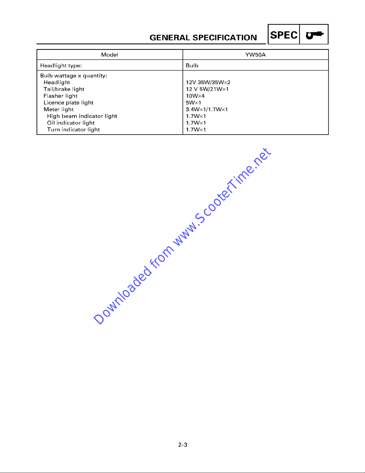
GENERAL SPECIFICATION
Downloaded from www.ScooterTime.net
Model YW50A
Headlight type: Bulb
Bulb wattage x quantity:
Headlight
Tail/brake light
Flasher light
Licence plate light
Meter light
High beam indicator light
Oil indicator light
Turn indicator light
12V 35W/35Wx2
12 V 5W/21Wx1
10Wx4
5Wx 1
3.4Wxl/1.7Wxl
1.7Wx 1
1.7Wx 1
1.7Wx 1
IsPEcl.-I
2-3

MA...E°A.OE SPEO.F.OA -.O° ISPEcl I
Downloaded from www.ScooterTime.net
MAINTENANCE SPECIFICATION
ENGINE
Item Sta nda rd Limit
Cylinder head:
Warp limit "~
*Lines indicate straightedge measurement
Cylinder:
Bore size
Taper limit
Out of round Ih-nit
Piston:
Piston to cylinder clearance
Piston size "D"
Measuring point "H"
Piston pin bore inside diameter
Piston pin outside diameter
Piston Ring:
Sectional Sketch (B × T)/'l-ype
Top Ring
2nd Ring
End Gap (Installed):
Top Ring
2nd Ring
Side Clearance ( Installed):
Top Ring
2nd Ring
I~ Yl
40.000~40.014mm
(1.5748~1.5754 in)
0.035~0.040 mm
(0.0014~0.0016 in)
39.958~39.972 mm
(1.5731~1.5737 in)
5 mm(O.2 in)
10.004~10.015 mm
(0.3939~0.3943 in)
9.996~10.000 rnrn
(0.3935~0.3937 in)
1.2 × 1.6 mm/keystone
(0.05 × 0.06 in)
1.2 × 1.6 ram/keystone
(0.05 × 0.06 in)
0.15~0.35 mm
(0.005~0.01 in)
0.15~0.35 mm
(0.005~0.01 in)
0.03~0.05 mm
(0.0012~0.0020 in)
0.03~0.05 mm
(0.0012~0.0020 in)
0.03 mm
(0.0012 in)
40.10 mm
(1.5787 in)
0.05 mm
(0.0020 in)
0.03 rnm
(0.0012 in)
0.10 mm
(0.0039 in)
10.045 mm
(0.4 in)
9.975 mm
(0.39 in)
0.6 mm(O.02 in)
0.6 mm(O.02 in)
0.1 mm(O.O039 in)
0.1 mm(O.O039 in)
2-4
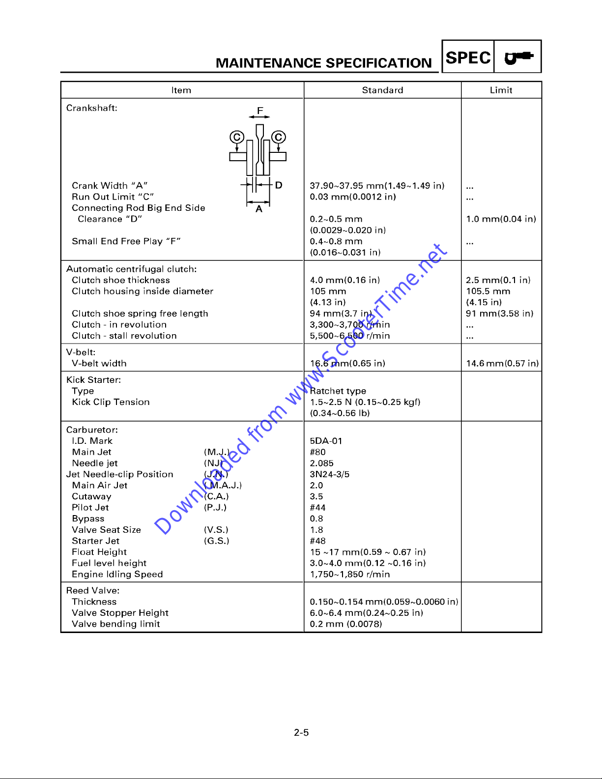
MA..TE°A°OE SPEO.F.OAT.O° ISPEcl " I
Downloaded from www.ScooterTime.net
Item Standard Limit
Crankshaft:
Crank Width
Run Out Limit "C"
Connecting Rod Big End Side
Clearance
Small End Free Play
Automatic centrifugal clutch:
Clutch shoe thickness
Clutch housing inside diameter
Clutch shoe spring free length
Clutch - in revolution
Clutch - stall revolution
V-belt:
V-belt width
Kick Starter:
Type
Kick Clip Tension
"A"
"D"
"F"
F
- "--D
.q- .~p
A
37.90~37.95 mm(1.49~1.49 in)
0.03 mm(0.0012 in)
0.2~0.5 mm
(0.0029~0.020 in)
0.4~0.8 mm
(0.016~0.031 in)
4.0 mm(0.16 in)
105 mm
(4.13 in)
94 mm(3.7 in)
3,300~3,700 r/min
5,500~6,500 r/rain
16.6 mm(0.65 in)
Ratchet type
1.5~2.5 N (0.15~0.25 kgf)
(0.34~0.56 Ib)
1.0 mm(0.04 in)
2.5 mm(0.1 in)
105.5 mm
(4.15 in)
91 mm(3.58 in)
14.6 mm(0.57 in)
Carburetor:
I.D. Mark
Main Jet
Needle jet
Jet Needle-clip Position
Main Air Jet
Cutaway
Pilot Jet
Bypass
Valve Seat Size
Starter Jet
Float Height
Fuel level height
Engine Idling Speed
Reed Valve:
Thickness
Valve Stopper Height
Valve bending limit
(M.J.)
(N J)
(J.N.)
(M.A.J.)
(C.A.)
(P.J.)
(V.S.)
(G.S.)
5DA-01
#8O
2.085
3N24-3/5
2.0
3.5
#44
0.8
1.8
#48
15 ~17 ram(0.59 ~ 0.67 in)
3.0~4.0 rnrn(0.12 ~0.16 in)
1,750~1,850 r/rain
0.150~0.154 mm(0.059~0.0060 in)
6.0~6.4 mm(0.24~0.25 in)
0.2 mm (0.0078)
2-5
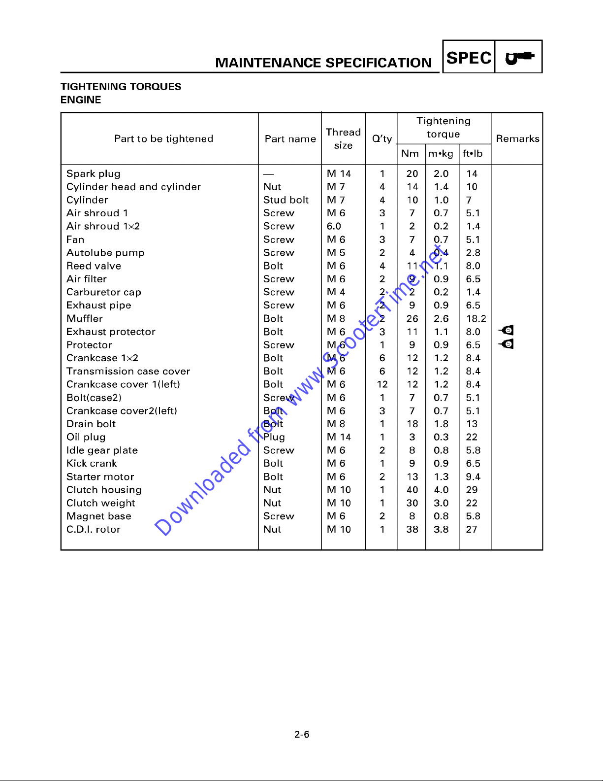
TIGHTENING TORQUES
Downloaded from www.ScooterTime.net
ENGINE
Part to be tightened
M..°TE°..OE SPEO.F.C.T.O. ISPEcl "" I
Tightening
Part name
Thread Q'ty torque
size
Nm m°kg ft°lb
Remarks
Spark plug
Cylinder head and cylinder
Cylinder
Air shroud 1
Air shroud lx2
Fan
Autolube pump
Reed valve
Air filter
Carburetor cap
Exhaust pipe
Muffler
Exhaust protector
Protector
Crankcase lx2
Transmission case cover
Crankcase cover 1(left)
Bolt(case2)
Crankcase cover2(left)
Drain bolt
Oil plug
Idle gear plate
Kick crank
Starter motor
Clutch housing
Clutch weight
Magnet base
C.D.I. rotor
m
Nut
Stud bolt
Screw
Sc rew
Screw
Screw
Bolt
Sc rew
Screw
Screw
Bolt
Bolt
Screw
Bolt
Bolt
Bolt
Screw
Bolt
Bolt
Plug
Screw
Bolt
Bolt
Nut
Nut
Screw
Nut
M 14 1 20 2.0 14
M 7 4 14 1.4 10
M 7 4 10 1.0 7
M 6 3 7 0.7 5.1
6.0 1 2 0.2 1.4
M 6 3 7 0.7 5.1
M 5 2 4 0.4 2.8
M 6 4 11 1.1 8.0
M 6 2 9 0.9 6.5
M 4 2 2 0.2 1.4
M 6 2 9 0.9 6.5
M 8 2 26 2.6 18.2
M 6 3 11 1.1 8.0
M 6 1 9 0.9 6.5
M 6 6 12 1.2 8.4
M 6 6 12 1.2 8.4
M 6 12 12 1.2 8.4
M 6 1 7 0.7 5.1
M 6 3 7 0.7 5.1
M 8 1 18 1.8 13
M 14 1 3 0.3 22
M 6 2 8 0.8 5.8
M 6 1 9 0.9 6.5
M 6 2 13 1.3 9.4
M 10 1 40 4.0 29
M 10 1 30 3.0 22
M 6 2 8 0.8 5.8
M 10 1 38 3.8 27
2-6
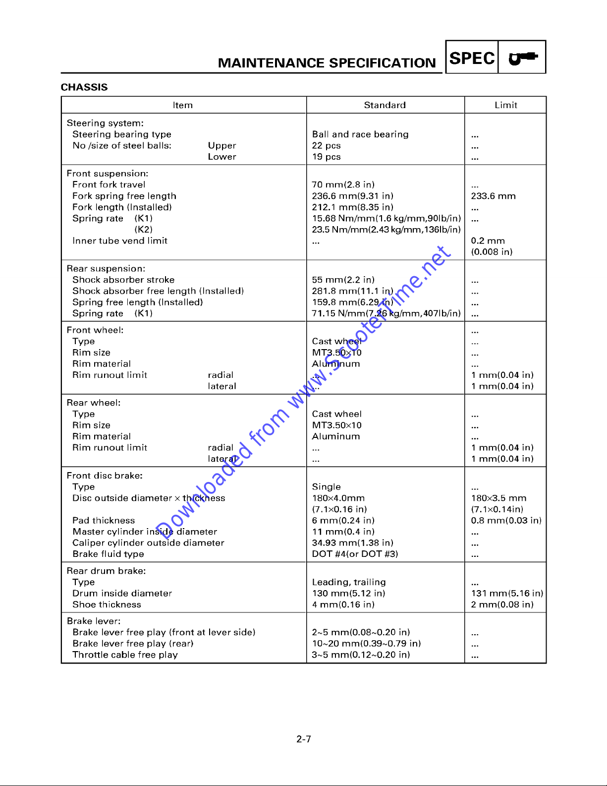
MA. A.OE SPEO.F.OAT.O. ISPEcl " I
Downloaded from www.ScooterTime.net
CHASSIS
Item Standard Limit
Steering system:
Steering bearing type Ball and race bearing ...
No/size of steel balls: Upper 22 pcs ...
Lower 19 pcs ...
Front suspension:
Front fork travel
Fork spring free length
Fork length (Installed)
Spring rate (K1)
(K2)
Inner tube vend limit
Rear suspension:
Shock absorber stroke
Shock absorber free length (Installed)
Spring free length (Installed)
Spring rate (K1)
Front wheel:
Type
Rim size
Rim material
Rim runout limit
Rear wheel:
Type
Rim size
Rim material
Rim runout limit
radial
lateral
radial
lateral
70 rnrn(2.8 in)
236.6 mm(9.31 in)
212.1 mm(8.35 in)
15.68 Nm/mm(1.6 kg/mm,901b/in)
23.5 Nm/mm(2.43
55 mm(2.2 in)
281.8 rnrn(11.1 in)
159.8 mm(6.29 in)
71.15 N/mm(7.26 kg/mm,4071b/in)
Cast wheel
MT3.50xl 0
Aluminum
Cast wheel
MT3.50xl 0
Aluminum
kg/mm,1361b/in)
233.6 mm
0.2 mm
(0.008 in)
1 mm(0.04 in)
1 ram(0.04 in)
1 mm(0.04 in)
1 mm(0.04 in)
Front disc brake:
Type
Disc outside diameter x thickness
Pad thickness
Master cylinder inside diameter
Caliper cylinder outside diameter
Brake fluid type
Rear drum brake:
Type
Drum inside diameter
Shoe thickness
Brake lever:
Brake lever free play (front at lever side)
Brake lever free play (rear)
Throttle cable free play
Single
180x4.0mm
(7.1x0.16 in)
6 ram(0.24 in)
11 mm(0.4 in)
34.93 mm(1.38 in)
DOT #4(or DOT #3)
Leading, trailing
130 mm(5.12 in)
4 ram(0.16 in)
2~5 mm(0.08~0.20 in)
10~20 mm(0.39~0.79 in)
3~5 mm(0.12~0.20 in)
2-7
180x3.5 mm
(7.1x0.14in)
0.8 mm(0.03 in)
131 mm(5.16 in)
2 ram(0.08 in)
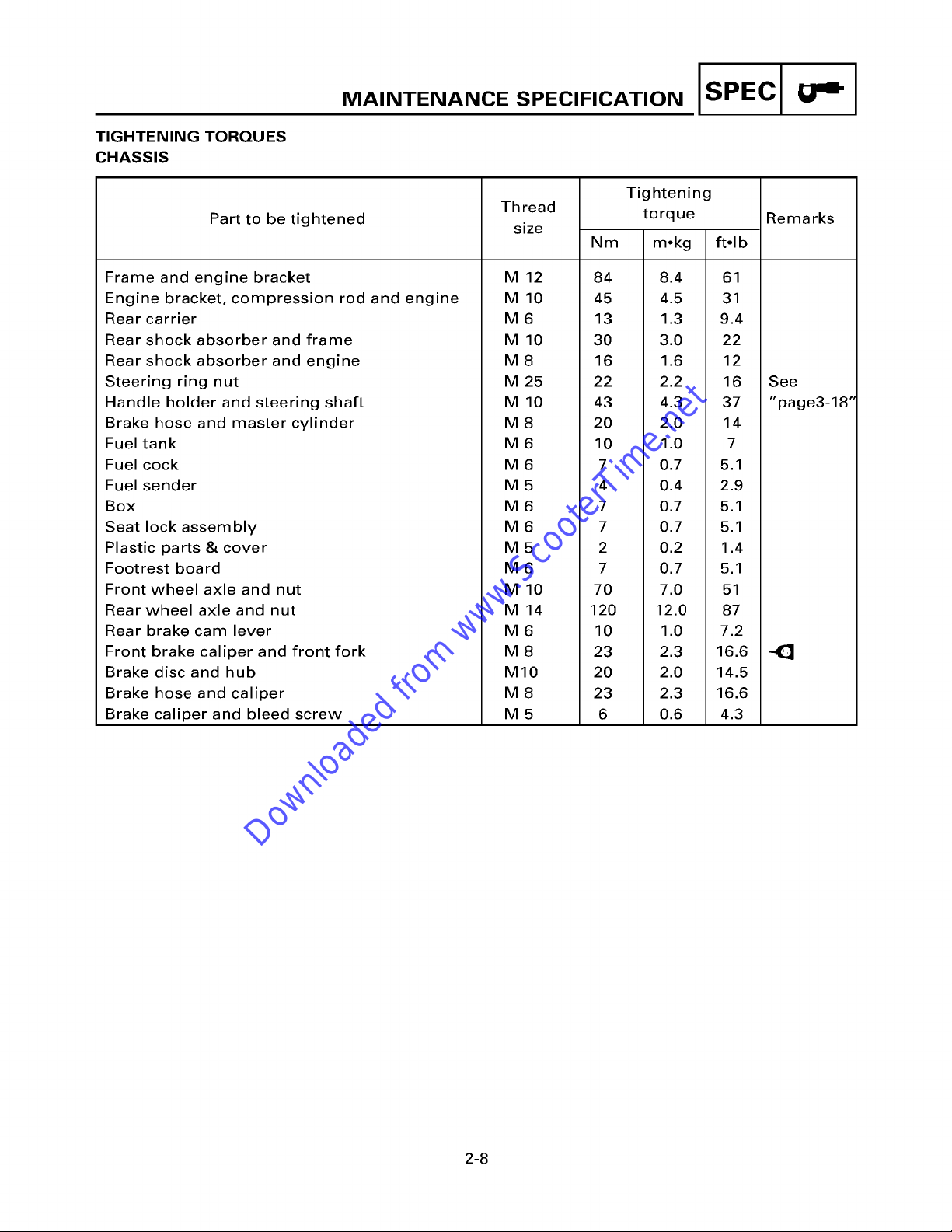
TIGHTENING TORQUES
Downloaded from www.ScooterTime.net
CHASSIS
Part to be tightened
MA. A.OE SPEO.F.OAT.O. ISPEcl "" I
Tightening
Th read torque Remarks
size
Nm m,kg ft°lb
Frame and engine bracket
Engine bracket, compression rod and engine
Rear carrier
Rear shock absorber and frame
Rear shock absorber and engine
Steering ring nut
Handle holder and steering shaft
Brake hose and master cylinder
Fuel tank
Fuel cock
Fuel sender
Box
Seat lock assembly
Plastic parts & cover
Footrest board
Front wheel axle and nut
Rear wheel axle and nut
Rear brake cam lever
Front brake caliper and front fork
Brake disc and hub
Brake hose and caliper
Brake caliper and bleed screw
M 12 84 8.4 61
M 10 45 4.5 31
M 6 13 1.3 9.4
M 10 30 3.0 22
M 8 16 1.6 12
M 25 22 2.2 16 See
M 10 43 4.3 37 "page3-18"
M 8 20 2.0 14
M 6 10 1.0 7
M 6 7 0.7 5.1
M 5 4 0.4 2.9
M 6 7 0.7 5.1
M 6 7 0.7 5.1
M 5 2 0.2 1.4
M 6 7 0.7 5.1
M 10 70 7.0 51
M 14 120 12.0 87
M 6 10 1.0 7.2
M 8 23 2.3 16.6 41~
MIO 20 2.0 14.5
M 8 23 2.3 16.6
M 5 6 0.6 4.3
2-8
 Loading...