


2009
MOTORCYCLE
SERVICE MANUAL
Model : YW125Y_
32SF819770E0
*32SF819770E0*
EAS00000
YW125Y 2009
SERVICE MANUAL
©2008 by Yamaha Motor Taiwan Co., Ltd.
First edition, July 2008
All rights reserved.
Any reproduction or unauthorized use
without the written permission of
Yamaha Motor Taiwan Co., Ltd.
is expressly prohibited.
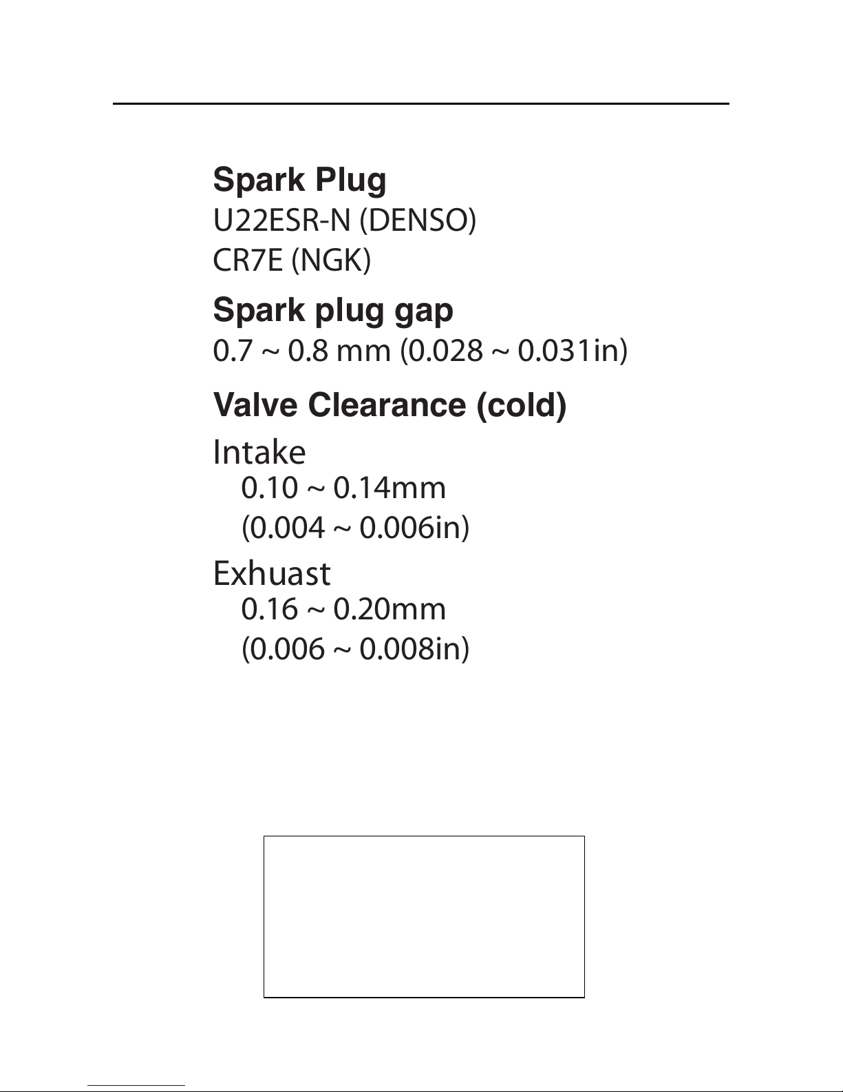
0.10 ~ 0.14mm
(0.004 ~ 0.006in)
0.16 ~ 0.20mm
(0.006 ~ 0.008in)
Valve Clearance (cold)
Intake
Exhuast
Spark plug gap
0.7 ~ 0.8 mm (0.028 ~ 0.031in)
Spark Plug
U22ESR-N (DENSO)
CR7E (NGK)
EAS20070
IMPORTANT
This manual was produced by the Yamaha Motor Taiwan Company, Ltd. primarily for use by Y amaha
dealers and their qualified mechanics. It is not possible to include all the knowledge of a mechanic in
one manual. Therefore, anyone who uses this book to perform maintenance and repairs on Y amaha
vehicles should have a basic understanding of mechanics and the techniques to repair these types
of vehicles. Repair and maintenance work attempted by anyone without this knowledge is likely to
render the vehicle unsafe and unfit for use.
This model has been designed and manufactured to perform within certain specifications in regard
to performance and emissions. Proper service with the correct tools is necessary to ensure that the
vehicle will operate as designed. If there is any question about a service procedure, it is imperative
that you contact a Yamaha dealer for any service information changes that apply to this model. This
policy is intended to provide the customer with the most satisfaction from his vehicle and to conform
to federal environmental quality objectives.
Yamaha Motor Taiwan Company , Ltd. is continually striving to improve all of its models. Modifications
and significant changes in specifications or procedures will be forwarded to all authorized Yamaha
dealers and will appear in future editions of this manual where applicable.
TIP
• This Service Manual contains information regarding periodic maintenance to the emission control system. Please read this material carefully.
• Designs and specifications are subject to change without notice.
EAS20080
IMPORTANT MANUAL INFORMATION
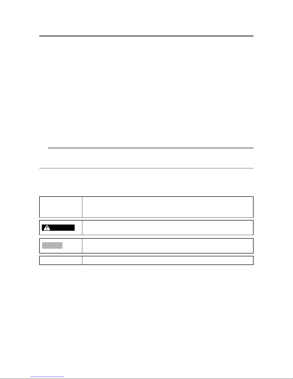
Particularly important information is distinguished in this manual by the following notations .
This is the safety alert symbol. It is used to alert you to potential personal
injury hazards. Obey all safety messages that follow this symbol to avoid
possible injury or death.
A W ARNING indicates a hazardous situation which, if not avoided, could
result in death or serious injury.
A NOTICE indicates special precautions that must be taken to avoid
damage to the vehicle or other property.
A TIP provides key information to make procedures easier or clearer.
Q
TIP
WARNING
NOTICE
EAS00007
HOW TO USE THIS MANUAL
This manual is intended as a handy, easy-to-read reference book for the mechanic. Comprehensiv e
explanations of all installation, removal, disassembly, assembly, repair and check procedures are
laid out with the individual steps in sequential order.
1 The manual is divided into chapters. An abbreviation and symbol in the upper right corner of
each page indicate the current chapter.]
Refer to “SYMBOLS”.
2 Each chapter is divided into sections. The current section title is sho wn at the top of each page,
except in Chapter 3 (“PERIODIC CHECKS AND ADJUSTMENTS”), where the sub-section
title(s) appears.
3 Sub-section titles appear in smaller print than the section title.
4 To help identify par ts and clar ify procedure steps, there are exploded diagrams at the start of
each removal and disassembly section.
5 Numbers are given in the order of the jobs in the exploded diagram. A circled number indicates
a disassembly step.
6 Symbols indicate parts to be lubricated or replaced.
Refer to “SYMBOLS”.
7 A job instruction chart accompanies the exploded diagram, pro viding the order of jobs, names of
parts, notes in jobs, etc.
8 Jobs requiring more information (such as special tools and technical data) are described se-
quentially.
5-32
ENG
RemarksOrder Job/Part Q’ty
1
2
3
4
5
6
7
8
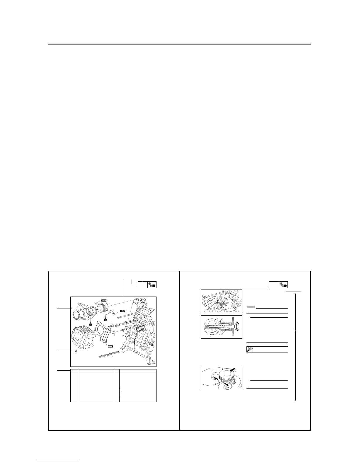
EAS00251
CYLINDER AND PISTON
Removing the cylinder and piston
Cylinder head
Timing chain guide (exhaust side)
Cylinder
Dowel pin
Cylinder gasket
Piston pin clip
Piston pin
Piston
Piston ring set
Remove the parts in the order listed.
Refer to “CYLINDER HEAD”.
Refer to “REMOVING THE CYLINDER
AND PISTON” and “INSTALLING THE
PISTON AND CYLINDER”.
For installation, reverse the removal procedure.
1
1
2
1
2
1
1
1
CYLINDER AND PISTON
5
8
6
5
3
3
4
2
1
7
ENG
5-33
3
2
1
EAS00253
REMOVING THE CYLINDER AND PIST ON
1. Remove:
8piston pin clip 1
8piston pin 2
8piston 3
NOTICE
Do not use a hammer to drive the piston pin
out.
TIP
8 Before removing the piston pin clip, cover
the crankcase opening with a clean rag to
prevent the piston pin clip from falling into
the crankcase.
8 Before removing the piston pin, deburr the
piston pin clip’s groove and the piston’s pin
bore area.
8 If both areas are deburred and the piston
pin is still difficult to remove, remove it with
the piston pin puller set 4.
Piston pin puller set
90890-01304 (YU-01304)
CYLINDER AND PISTON
2. Remove:
8top ring
82nd ring
8oil ring
TIP
When removing a piston ring, open the end gap
with your fingers and lift the other side of the
ring over the piston crown.
3
2
4
4
5
7
6 2 1
3
8
GEN
INFO
SPEC
CHK
ADJ
ENG
TRBL
SHTG
CHAS
-+
ELEC
4
M
B
LS
New
M
G
COOL
12
34
56
78
90
qw
er
i
s
hj
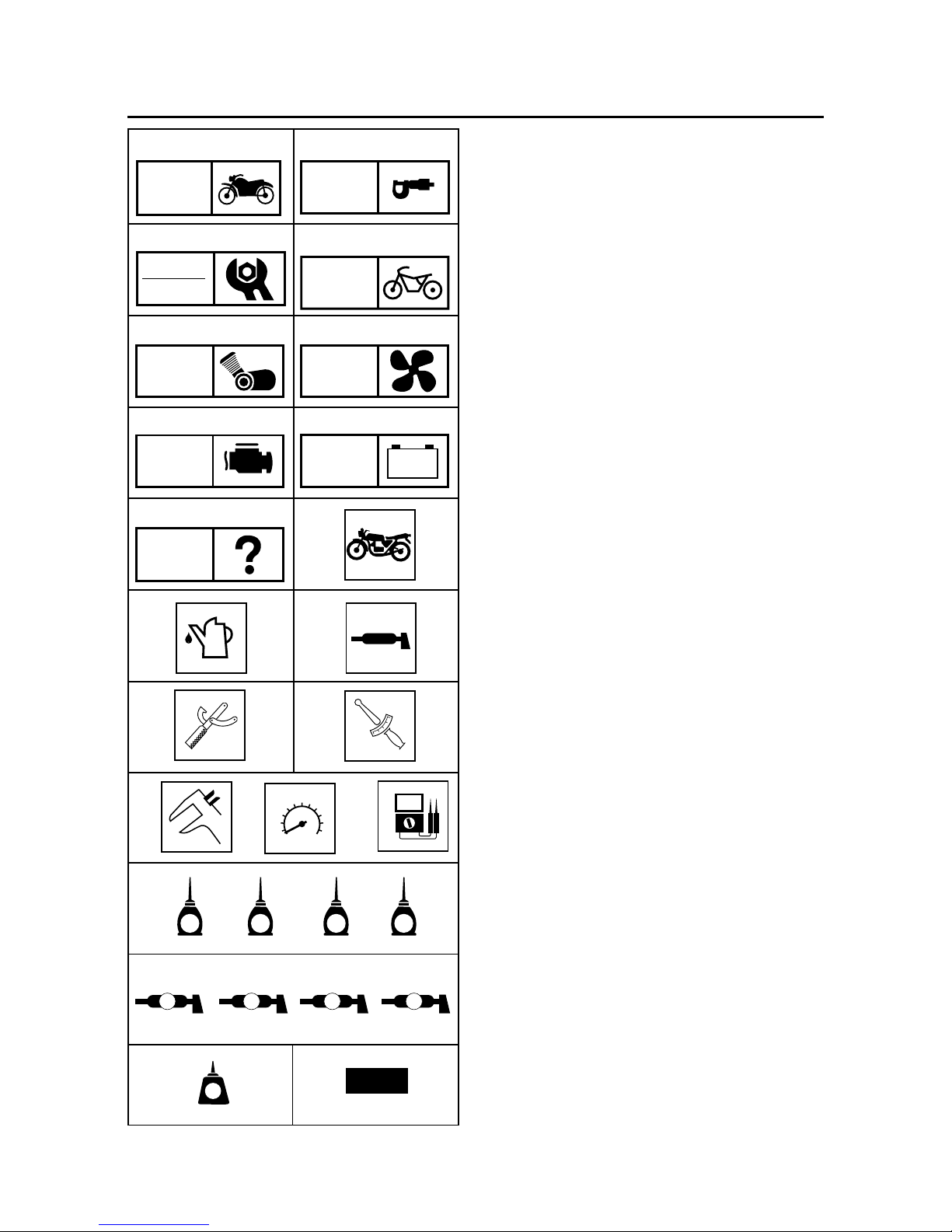
EAS00008
SYMBOLS
The following symbols are not relevant to every
vehicle.
Symbols 1 to 9 indicate the subject of each
chapter.
1 General information
2 Specifications
3 Periodic checks and adjustments
4 Chassis
5 Engine
6 Cooling system
7 Fuel injection system
8 Electrical system
9 Troubleshooting
Symbols 0 to u indicate the following.
0 Serviceable with engine mounted
q Filling fluid
w Lubricant
e Special tool
r Tightening torque
t Wear limit, clearance
y Engine speed
u Electrical data
Symbols i to g in the exploded diagrams indi-
cate the types of lubricants and lubrication
points.
i Engine oil
o Gear oil
p Molybdenum-disulfide oil
a Brake fluid
s Wheel-bearing grease
d Lithium-soap- based grease
f Molybdenum-disulfide grease
g Silicone grease
Symbols h to j in the exploded diagrams indi-
cate the following.
h Apply locking agent (LOCTITE
®
)
j Replace the part
T
R
.
.
t y u
LT
BF
opa
S
dfg
FI
EAS00011
TABLE OF CONTENTS
GENERAL INFORMATION
SPECIFICATIONS
PERIODIC CHECKS AND
ADJUSTMENTS
CHASSIS
ENGINE
FUEL INJECTION SYSTEM
ELECTRICAL SYSTEM
TROUBLESHOOTING
-+
GEN
INFO
SPEC
CHK
ADJ
CHAS
ENG
FI
ELEC
TRBL
SHTG
1
2
3
4
5
6
7
8

1-13
GEN
INFO
CHAPTER 1
GENERAL INFORMATION
SCOOTER IDENTIFICATION ................................................................... 1-1
VEHICLE IDENTIFICATION NUMBER ............................................. 1-1
MODEL LABEL .................................................................................. 1-1
FEATURES ............................................................................................... 1-2
OUTLINE OF THE FI SYSTEM.........................................................1-2
FI SYSTEM ........................................................................................1-3
O2 sensor ............................................................................................1-4
IMPORTANT INFORMATION ...................................................................1-5
PREPARATION FOR REMOVAL AND DISASSEMBLY ................... 1-5
REPLACEMENT PARTS ................................................................... 1-5
GASKETS, OIL SEALS AND O-RINGS ............................................1-5
LOCK WASHERS/PLATES AND COTTER PINS............................. 1-6
BEARINGS AND OIL SEALS ............................................................ 1-6
CIRCLIPS........................................................................................... 1-6
EQUIPMENT PREPARATION ........................................................... 1-7
CHECKING THE CONNECTIONS ........................................................... 1-8
SPECIAL TOOLS......................................................................................1-9
1-1
GEN
INFO
SCOOTER IDENTIFICATION
EAS00015
GENERAL INFORMA TION
SCOOTER IDENTIFICATION
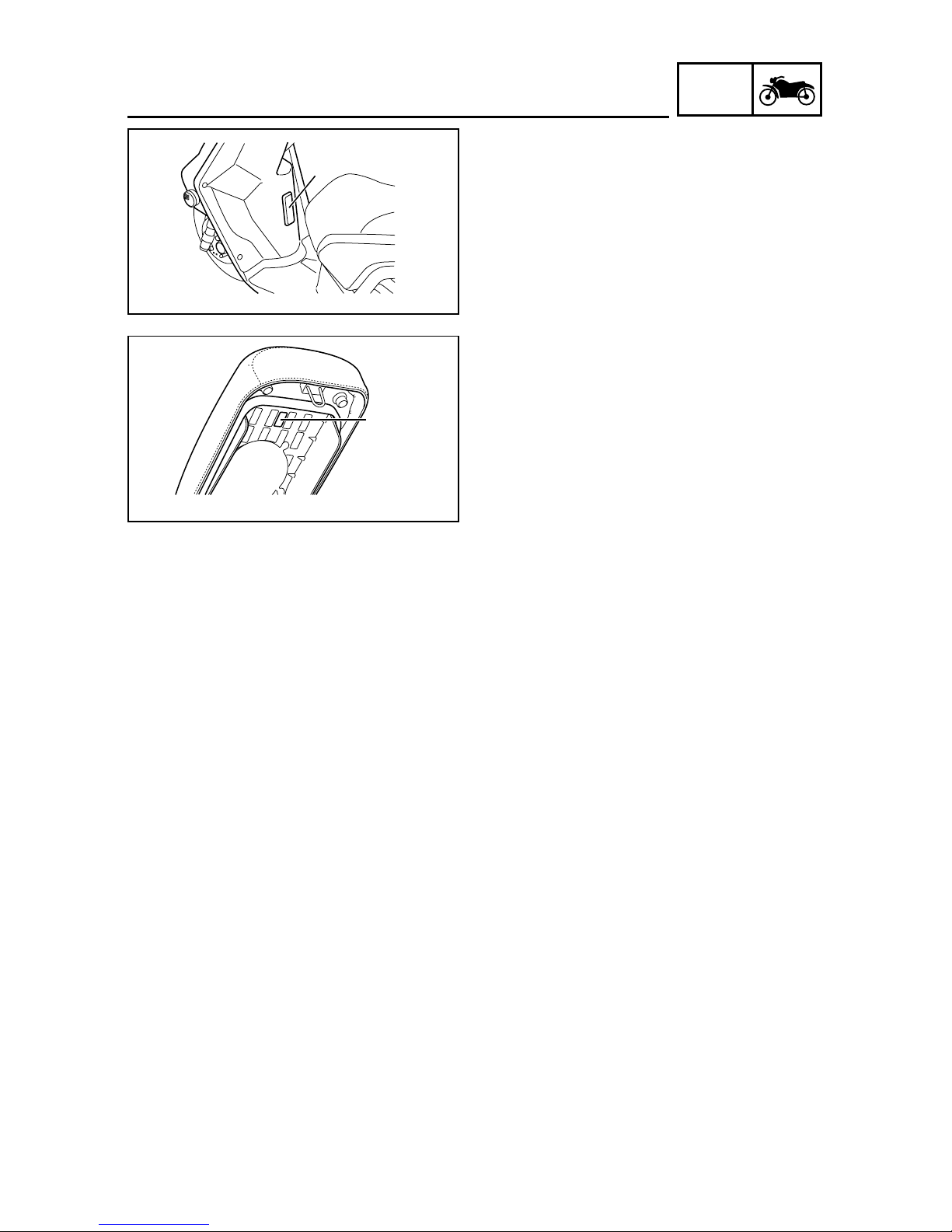
EAS00017
VEHICLE IDENTIFICATION NUMBER
The vehicle identification number 1 is stamped
into the frame.
EAS00018
MODEL LABEL
The model label 1 is affixed to the frame under
the seat. This information will be needed to order spare parts.
1
1
1-2
GEN
INFO
EAS00896
FEATURES
OUTLINE OF THE FI SYSTEM
The main function of a fuel supply system is to provide fuel to the combustion chamber at the optimum air-fuel ratio in accordance with the engine operating conditions and the atmospheric temperature. In the conventional carburetor system, the air-fuel ratio of the mixture that is supplied to the
combustion chamber is created by the volume of the intake air and the fuel that is metered by the jet
used in the respective carburetor.
Despite the same volume of intake air, the fuel volume requirement varies by the engine operating
conditions, such as acceleration, deceleration, or operation under a heavy load. Carburetors that
meter the fuel through the use of jets have been provided with various auxiliary devices, so that an
optimum air-fuel ratio can be achieved to accommodate the constant changes in the operating conditions of the engine.
As the requirements for the engine to deliver more performance and cleaner exhaust gases increase, it becomes necessary to control the air-fuel ratio in a more precise and finely tuned manner.
To accommodate this need, this model has adopted an electronically controlled fuel injection(FI)
system, in place of the conventional carburetor system. This system can achieve an optimum airfuel ratio required by the engine at all times by using a microprocessor that regulates the fuel injection volume according to the engine operating conditions detected by various sensors.
The adoption of the FI system has resulted in a highly precise fuel supply, improved engine response, better fuel economy, and reduced exhaust emissions.
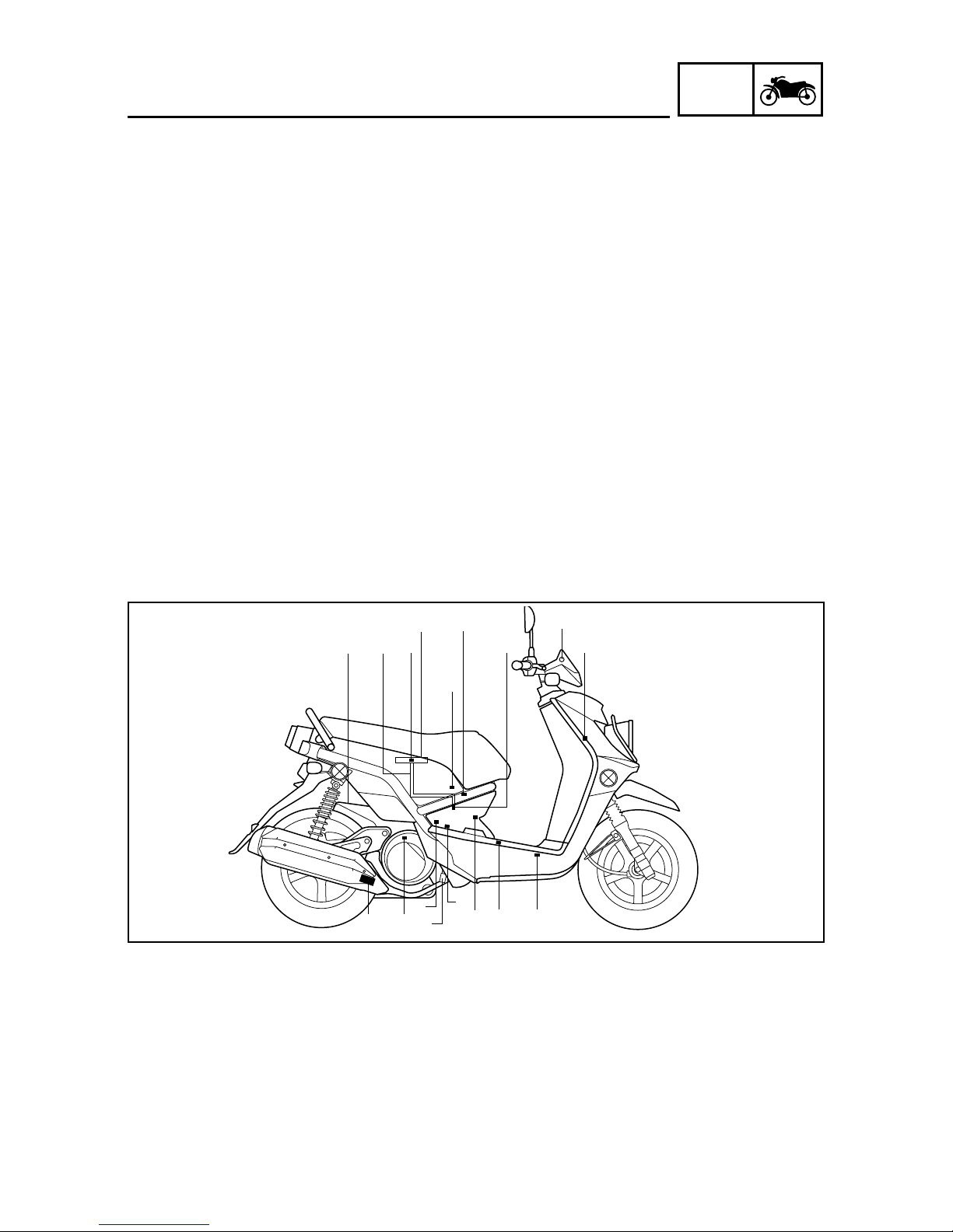
1 ECU
2 Engine trouble warning light
3 Lean angle cut-off switch
4 Fuel hose
5 Ignition coil
6 Fuel injector
7 Intake air pressure sensor
8 ISC(idle speed control) valve
9 Intake air temperature sensor
0 Battery
q Air filter case
w Catalytic converter
e Crankshaft position sensor
r Engine temperature sensor
t Spark plug
y Fuel tank
u Fuel pump
i Throttle position sensor
o O
2
sensor
FEATURES
q
4 7
9
i
u
y
8
6
1
2
30
t
ew
o
5
r
1-3
GEN
INFO
FEATURES
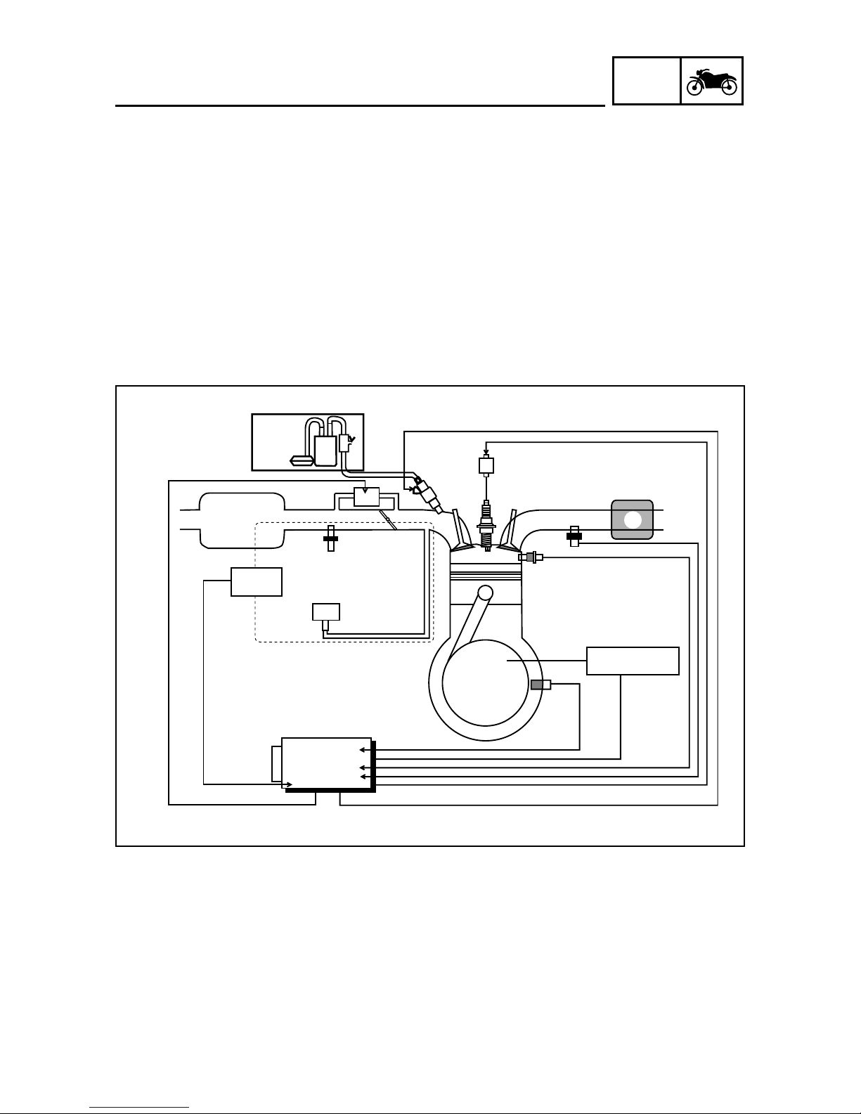
EAS00897
FI SYSTEM
The fuel pump delivers fuel to the fuel injector via the fuel filter. The pressure regulator maintains the
fuel pressure that is applied to the fuel injector at only 250 kPa (2.5 kgf/cm
2
, 35.6 psi). Accordingly,
when the energizing signal from the ECU energizes the fuel injector, the fuel passage opens , causing the fuel to be injected into the intake manifold only during the time the passage remains open.
Therefore, the longer the length of time the fuel injector is energized (injection duration), the greater
the volume of fuel that is supplied. Conversely, the shor ter the length of time the fuel injector is
energized (injection duration), the lesser the volume of fuel that is supplied.
The injection duration and the injection timing are controlled by the ECU. Signals that are input from
the crankshaft position sensor, intake air pressure sensor, intake temperature sensor and engine
temperature sensor enable the ECU to determine the injection duration. The injection timing is determined through the signals from the crankshaft position sensor. As a result, the volume of fuel that is
required by the engine can be supplied at all times in accordance with the driving conditions.
1 Fuel pump
2 Fuel injector
3 Ignition coil
4 ECU
5 Catalytic converter
6 Engine temperature sensor
7 Crankshaft position sensor
8 Intake air pressure sensor
9 Throttle body assembly
0 Intake air temperature sensor
Illustration is for reference only.
q Air filter case
w ISC (idle speed control) valve
e Throttle position sensor
r O
2
sensor
A Fuel system
B Air system
C Control system
5
1
A
3
4
6
7
9
0
q
e
w
C
MAQS
B
8
REC./REG.
2
r
1-4
GEN
INFO
FEATURES
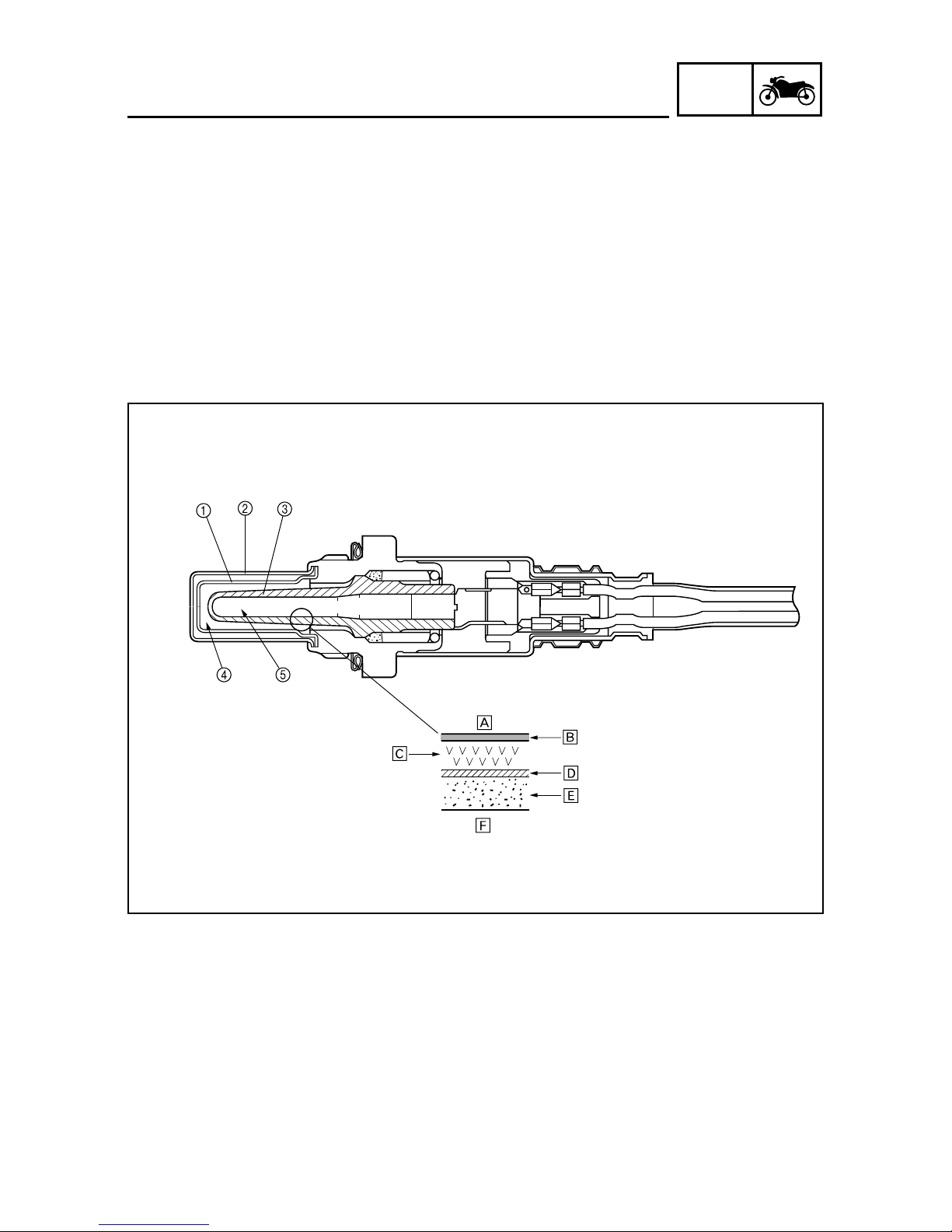
O2 sensor
The O2 sensor has been adopted to enable the catalyst to function at a high degree of efficiency by
maintaining the air-fuel mixture near the stoichiometric ratio (14.7:1). This sensor , which is a zirconia
type, utilizes the oxygen ion conductivity of the solid electrolyte for detecting the oxygen concentration levels. In actual operation, a zirconia tube made of solid electrolyte is exposed in the exhaust
gas, so that the exterior of the zirconia tube is in contact with the exhaust gas and the interior is in
contact with the atmosphere whose oxygen concentration level is known. When a difference in the
oxygen concentration level is created between the outside and the inside of the zirconia tube, the
oxygen ion passes through the zirconia element and generates an electromotiv e force. The electromotive force increases when the oxygen concentration level is low (rich air-fuel ratio) and the electromotive force decreases when the oxygen concentration level is high (lean air-fuel ratio). As electromotive force is generated in accordance with the concentration of the exhaust gas, the resultant
voltage is input into the ECU in order to correct the duration of the injection of fuel.
1 Inner cover
2 Outer cover
3 Zirconia tube
4 Exhaust gas
5 Atmosphere
A Atmosphere
B Inner electrode
C Zirconia element
D Outer electrode
E Porous ceramic layer
F Exhaust gas
1-5
GEN
INFO
IMPORTANT INFORMATION
EAS00020
IMPORTANT INFORMATION
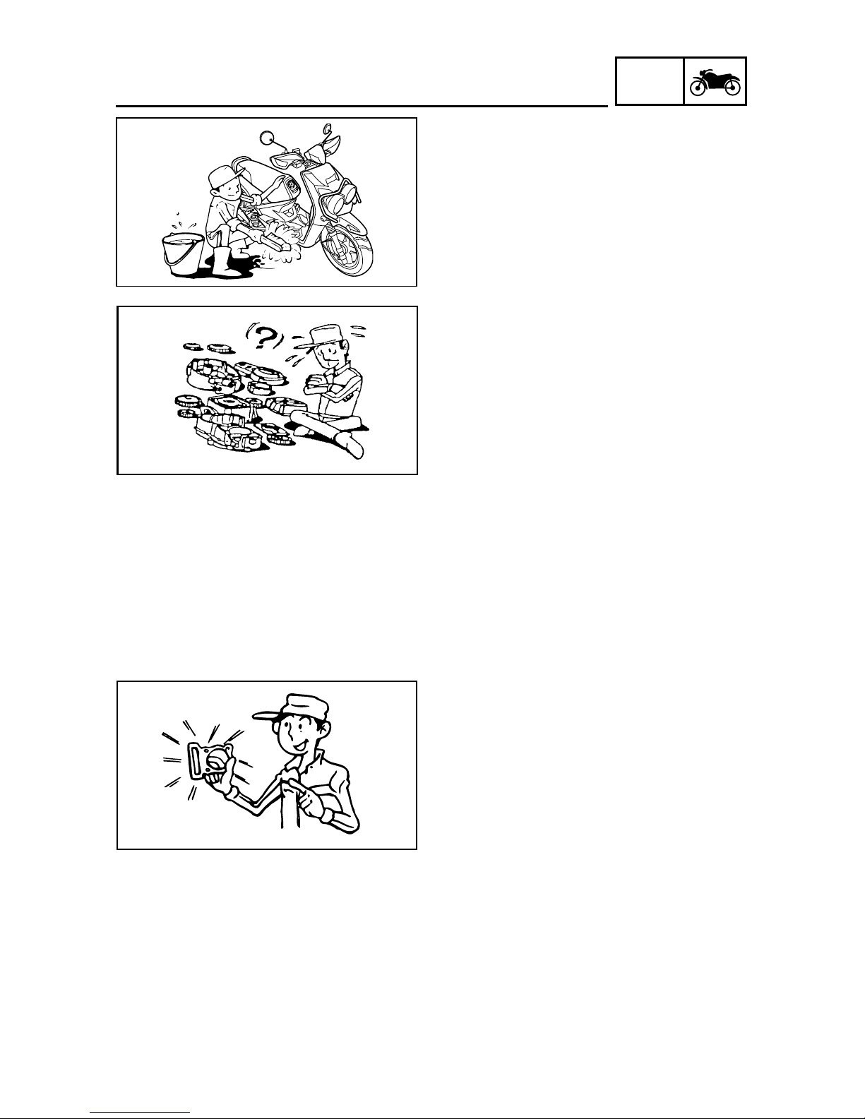
PREPARATION FOR REMO VAL AND DISASSEMBLY
1. Before removal and disassembly, remove
all dirt, mud, dust and foreign material.
2. Use only the proper tools and cleaning
equipment.
Refer to the “SPECIAL TOOLS”.
3. When disassembling, always keep mated
parts together. This includes gears, cylinders, pistons and other parts that have been
“mated” through normal wear. Mated parts
must always be reused or replaced as an
assembly.
4. During disassembly, clean all of the parts
and place them in trays in the order of disassembly. This will speed up assemb ly and
allow for the correct installation of all parts.
5. Keep all parts away from any source of fire .
EAS00021
REPLACEMENT PARTS
Use only genuine Yamaha parts for all replacements. Use oil and grease recommended by
Y amaha f or all lubrication jobs. Other brands may
be similar in function and appearance, but inferior in quality .
EAS00022
GASKETS, OIL SEALS AND O-RINGS
1. When overhauling the engine, replace all
gaskets, seals and O-rings. All gasket surfaces, oil seal lips and O-rings must be
cleaned.
2. During reassembly, properly oil all mating
parts and bearings and lubricate the oil seal
lips with grease.
1-6
GEN
INFO
IMPORTANT INFORMATION
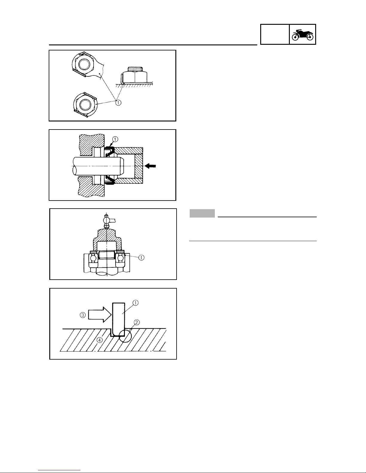
EAS00023
LOCK WASHERS/PLATES AND COTTER
PINS
After removal, replace all lock washers/plates
1 and cotter pins. After the bolt or nut has been
tightened to specification, bend the lock tabs
along a flat of the bolt or nut.
EAS00024
BEARINGS AND OIL SEALS
Install bearings and oil seals so that the
manufacturer’s marks or numbers are visible.
When installing oil seals, lubricate the oil seal
lips with a light coat of lithium-soap-based
grease. Oil bearings liberally when installing, if
appropriate.
1 Oil seal
NOTICE
Do not spin the bearing with compressed
air because this will damage the bearing
surfaces.
1 Bearing
EAS00025
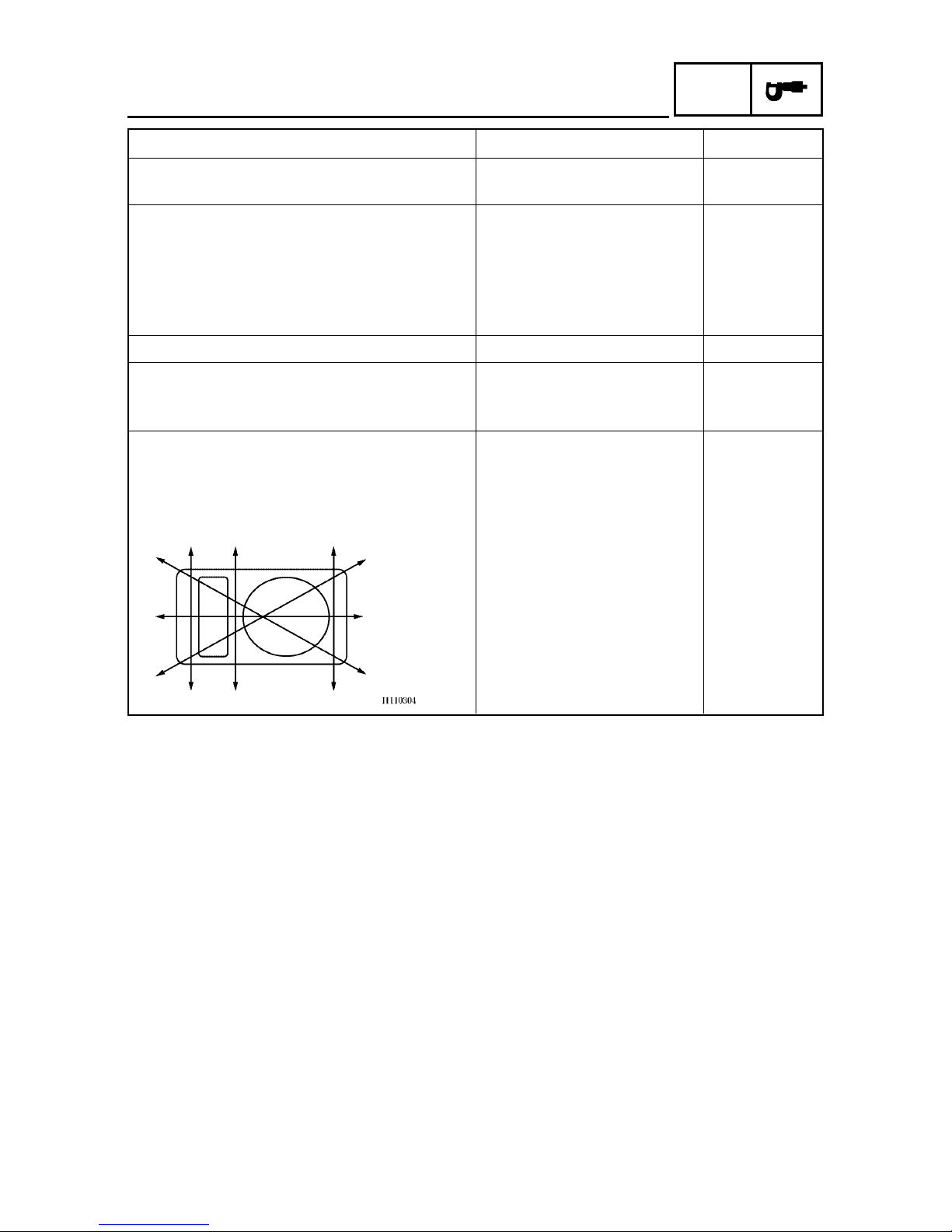
CIRCLIPS
Before reassembly, check all circlips carefully
and replace damaged or distorted circlips. Always replace piston pin clips after one use. When
installing a circlip 1, make sure the sharp-edged
corner 2 is positioned opposite the thrust 3
that the circlip receives.
4 Shaft

1-7
GEN
INFO
IMPORTANT INFORMATION
EAS00021
EQUIPMENT PREPARATION
Turn Rivet (Turn type)
Assembly status of the turn rivet(turn type).
Dissembling
1. Press center pin1 inward to release the
lock.
2. Remove the push rivet main body2.
Assembling
1. Restore the center pin, replace the turn rivet
main body.
2. Tur n in the center pin until leveling off with
the surface position of the turn rivet main
body.
1-8
GEN
INFO
CHECKING THE CONNECTIONS
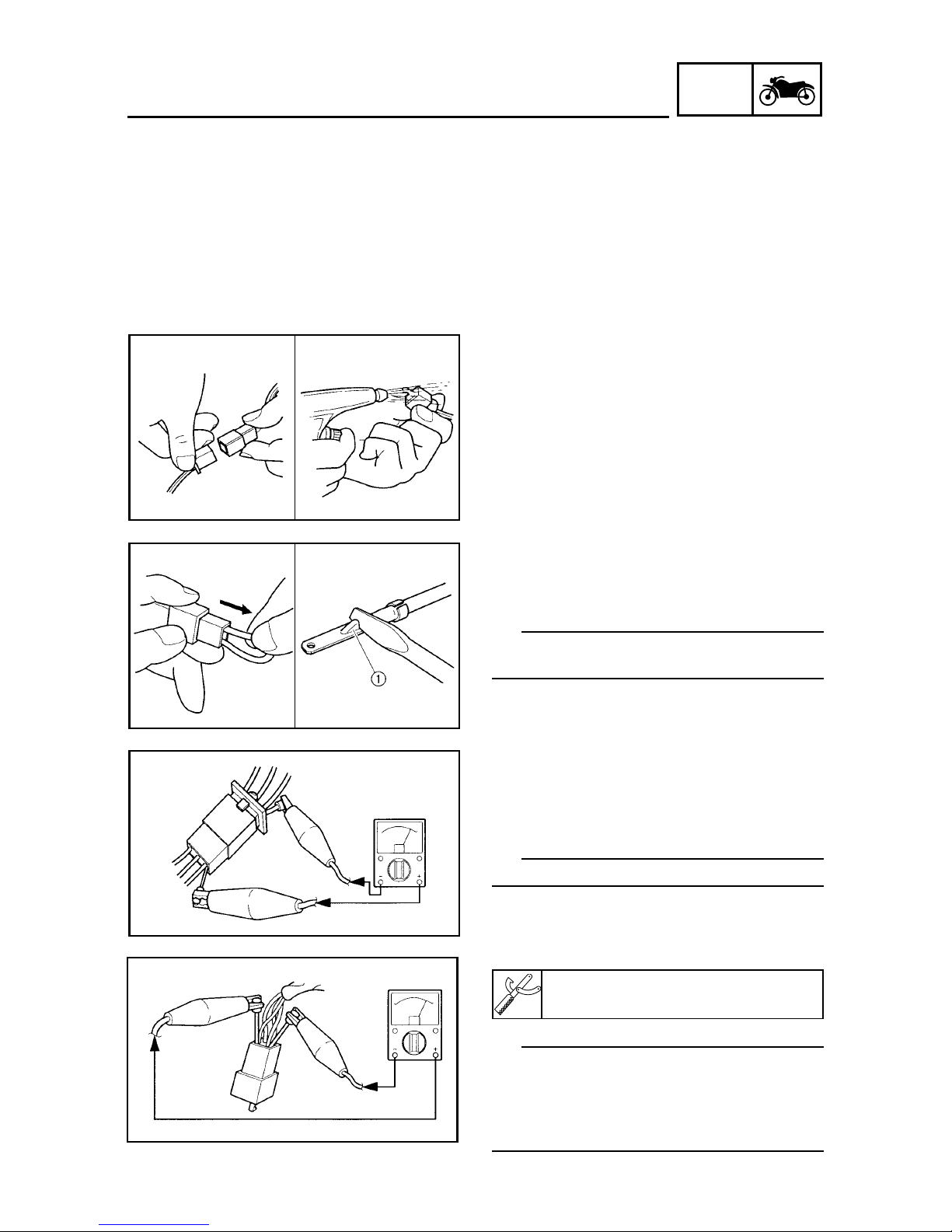
EAS00026
CHECKING THE CONNECTIONS
Check the leads, couplers, and connectors for
stains, rust, moisture, etc.
1. Disconnect:
8lead
8coupler
8connector
2. Check:
8lead
8coupler
8connector
Moisture J Dry with an air blower.
Rust/stains J Connect and disconnect
several times.
3. Check:
8all connections
Loose connection J Connect properly.
TIP
If the pin 1 on the terminal is flattened, bend it
up.
4. Connect:
8lead
8coupler
8connector
TIP
Make sure all connections are tight.
5. Check:
8continuity
(with the pocket tester)
Pocket tester
90890-03112 (YU-03112-C)
TIP
8 If there is no continuity, clean the terminals.
8 When checking the wire harness, perform
steps (1) to (3).
8 As a quick remedy , use a contact revitalizer
available at most part stores.
1-9
GEN
INFO
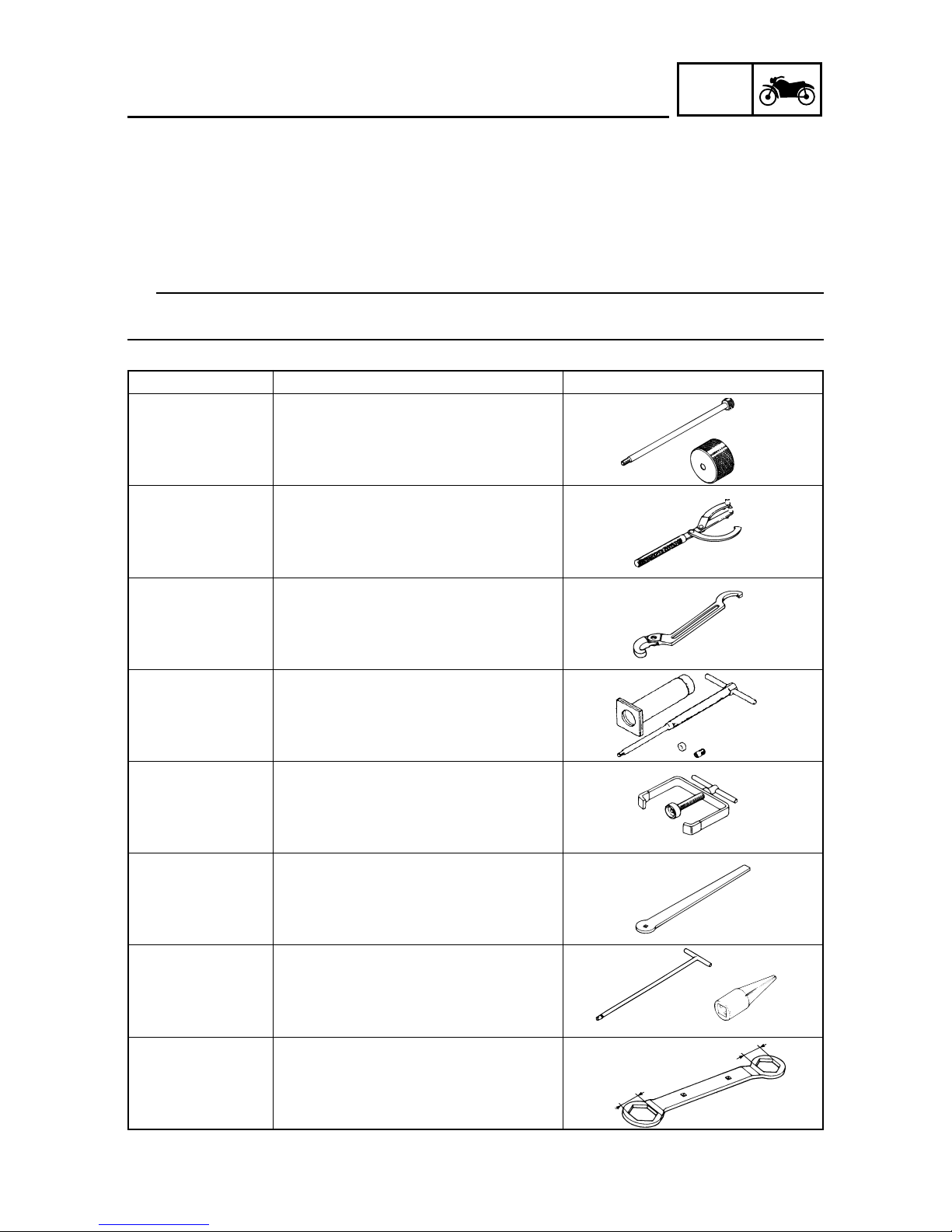
Tool NO.
Tool name / Function Illustration
90890-01085 (M8)
YU-01083-2
90890-01084
YU-01083-3
90890-01235
YU-01235
90890-01268
YU-01268
90890-01304
YU-01304
90890-01337
YM-33285
90890-01311
YM-08035-A
90890-01326
YM-01326
90890-01294
YM-01300-1
90890-01348
YM-01348
Slide hammer bolt (8mm) 1
Weight 2
These tools are needed to remove the camshaft.
Rotor holding tool
This tool is used to hold the primary fixed
sheave and secondary sheave assembly.
Ring nut wrench
This tool is used to loosen and tighten the
exhaust and steering ring nut.
Piston pin puller set
This tool is used to remove the piston pin.
Clutch spring holder
These tool are used for removing the nut with
holding the compression spring.
V alve adjusting tool
This tool is necessary for adjusting valve
clearance.
T-handle 1
Damper rod holder 2
These tools are used to hold the damper rod
when removing or installing the damper rod.
Lock nut wrench
This tool is used when removing or installing the secondary sheave nut.
SPECIAL TOOLS
1
2
1
2
EAS00027
SPECIAL TOOLS
The following special tools are necessary for complete and accurate tune-up and assembly. Use
only the appropriate special tools as this will help prevent damage caused by the use of inappropriate tools or improvised techniques. Special tools , part numbers or both may diff er depending on the
country.
When placing an order, refer to the list provided below to avoid any mistakes.
TIP
8 For U.S.A. and Canada, use part number starting with "YM-", "YU-", or "ACC-".
8 For others, use part number starting with "90890-".
41
46
1-10
GEN
INFO
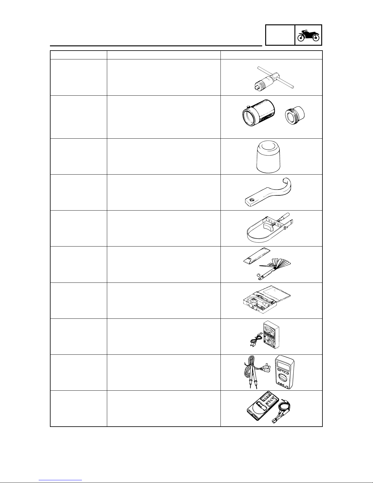
Tool NO.
Tool name / Function Illustration
SPECIAL TOOLS
90890-01189
YM-01189
90890-01367
YM-A9409-7
90890-01368
YM-A9409-4
90890-01384
YM-33299
90890-01403
YU-A9472
90890-01701
YS-01880-A
90890-03079
YM-34483
90890-03081
YU-33223
90890-03112
YU-03112-C
90890-03174
90890-06760
Flywheel puller
This tool is used for removing the AC magneto rotor.
Fork seal driver weight 1
Fork seal driver attachment (Ø33mm) 2
These tools are used when installing the fork
seal.
Oil seal guide
This tool is used for protecting the oil seal
lip when installing the secondary sliding
sheave.
Steering nut wrench
This tool is used to loosen and tighten the
steering ring nut.
Sheave holder
This tool is used for holding the secondary
sheave.
Thickness gauge
This tool is used to measure the valve
cleanance.
Compression gauge
This tool is used to measure the engine compression.
Pocket tester
This instrument is invaluable for checking
the electrical system.
Digital circuit tester
This instrument is invaluable for checking
the electrical system.
Digital tachometer
This tool is needed for detecting engine rpm.
1
2

1-11
GEN
INFO
Tool NO.
Tool name / Function Illustration
SPECIAL TOOLS
90890-03141
YU-03141
90890-04101
90890-04019
YM-04019
90890-04108
YM-04108
90890-04116
YM-04116
90890-04117
YM-04117
90890-04118
YM-04118
90890-06754
YM-34487
90890-03182
YU-03182
90890-03153
YU-03153
90890-03186
Timing light
This tool is used to check the ignition timing.
V alve lapper
This tool is needed to remove and install the
valve lifters.
V alve spring compressor
Compressor adapter (Ø19mm)
These tools are used when removing or installing the valve and the valve spring.
V alve guide remov er (4.5mm)
This tool is used to remove or install the
valve guides.
V alve guide installer (4.5mm)
This tool is used to install the valve guides.
V alve guide reamer (4.5mm)
This tool is used to rebore the new valve
guides.
Ignition checker
This tool is used to check the ignition system components.
FI diagnostic tool
Execute CO adjustment, confirm fault code,
self diagnosis tool.
Pressure gauge
This tool is used to measure fuel pressure.
Fuel pressure adapter
This tool is used to measure fuel pressure.
1-12
GEN
INFO
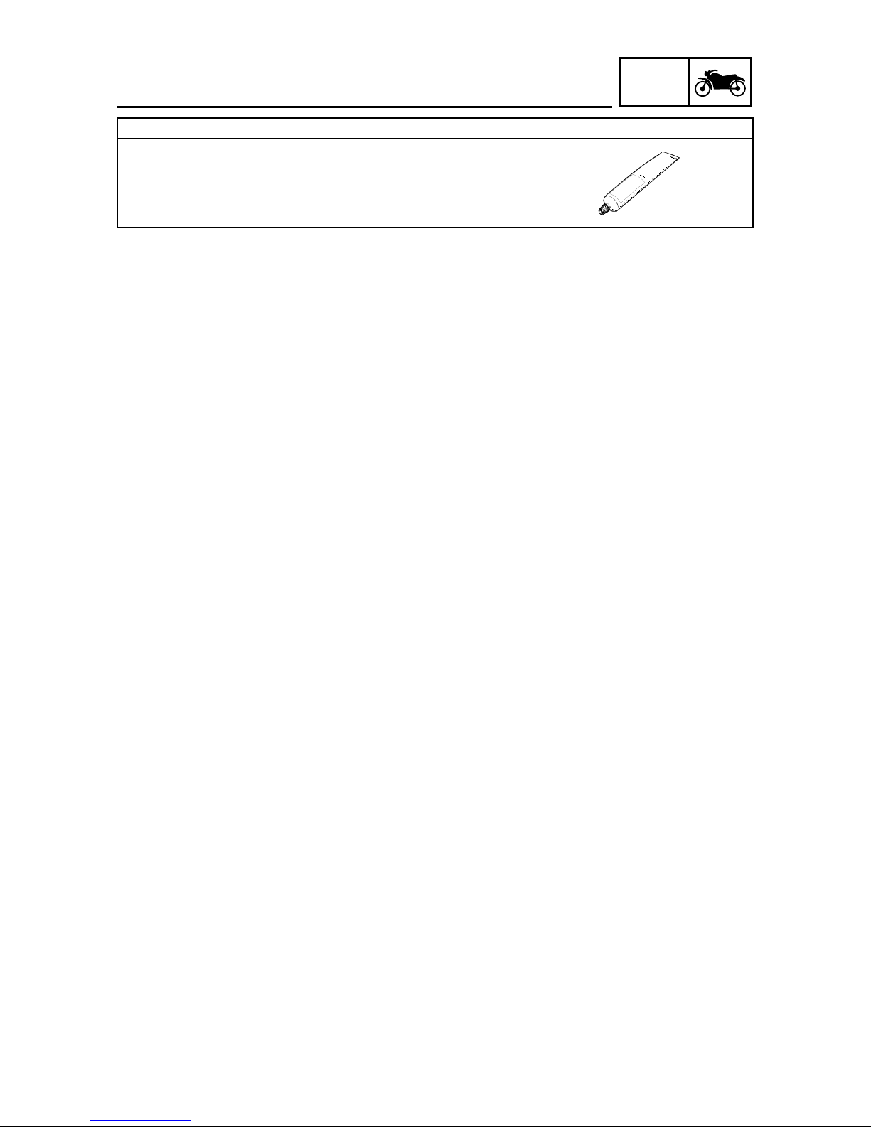
SPECIAL TOOLS
Tool NO.
Tool name / Function Illustration
90890-85505
ACC-11001-05-01
Y amaha bond NO .1215
Sealant (Quick Gasket®)
This sealant (bond) is used to apply on
crankcase mating surfaces.

2-32
SPEC
CHAPTER 2
SPECIFICATIONS
GENERAL SPECIFICATIONS .................................................................2-1
ENGINE SPECIFICATIONS ..................................................................... 2-2
CHASSIS SPECIFICATIONS ................................................................. 2-12
ELECTRICAL SPECIFICATIONS .......................................................... 2-15
GENERAL TIGHTENING TORQUE SPECIFICATIONS ....................... 2-18
TIGHTENING TORQUES........................................................................2-19
ENGINE............................................................................................2-19
CHASSIS..........................................................................................2-21
LUBRICATION POINTS AND LUBRICANT TYPES.............................2-23
ENGINE............................................................................................2-23
CHASSIS..........................................................................................2-25
CABLE ROUTING ..................................................................................2-26
2-1
SPEC
SPECIFICATIONS
GENERAL SPECIFICATIONS
Item
Standard Limit
GENERAL SPECIFICATIONS
Model
Code 32S1 (USA) …
32S2 (CAN) …
Dimensions
Overall length 1910mm (75.2in) …
Overall width 765mm (30.1in) …
Overall height 1110mm (43.7in) …
Seat height 780mm (30.7in) …
Wheelbase 1290mm (50.8in) …
Minimum ground clearance 125mm (4.9in) …
Minimum turning radius 1900mm (74.8in) …
Weight
Wet (with oil and a full fuel tank) 122kg (269lb) …
Dry (without oil and fuel) 116kg (256lb) …
Maximum load (total of cargo, rider, 155kg (342lb) …
passenger, and accessories)
2-2
SPEC
ENGINE SPECIFICATIONS
Item
Standard Limit
ENGINE SPECIFICATIONS
Engine
Engine type Air-cooled, 4-stroke, SOHC …
Displacement 0.125L (125cm
3,
7.63cu-in) …
Cylinder arrangement Forward inclined …
single cylinder
Bore × stroke 52.4 × 57.9mm (2.06 × 2.28in) …
Compression ratio 10:1 …
Engine idle speed 1700 ~ 1900r/min …
V acuum pressure at engine idle speed 37 ~ 47kPa …
(281 ~ 357mmHg,
11.06 ~ 14.05inHg)
at 1800r/min
Standard compression pressure 1350kPa …
(at sea level) (13.5kgf/cm
2
, 192psi)
at 1800r/min
Fuel
Recommended fuel Regular unleaded …
gasoline only
Fuel tank capacity
Total 6.0L …
(1.59 US gal, 1.32 Imp. gal)
Engine oil
Lubrication system Wet sump …
Recommended oil SAE20W-40 or SAE10W-30 …
API service SG type or higher
JASO standard MA
Quantity
Periodic oil change 0.80 ~ 0.90L …
(0.87 ~ 0.98 US qt,
0.74 ~ 0.83 Imp. qt)
Total amount 0.85 ~ 0.95L …
(0.9 ~ 1.0 US qt,
0.75 ~ 0.84 Imp. qt)
Final gear oil
Recommended oil SAE10W-30 type SE motor oil …
Periodic oil change 0.12 ~ 0.14L …
(0.13 ~ 0.15 US qt,
0.11 ~ 0.12 Imp. qt)
Total amount 0.14 ~ 0.16L …
(0.15 ~ 0.17 US qt,
0.12 ~ 0.14 Imp. qt)
2-3
SPEC
Item
Standard
Limit
ENGINE SPECIFICATIONS
Oil filter
Oil filter type Wire mesh …
Oil pump
Oil pump type Trochoid …
Inner rotor to outer rotor tip clearance 0.15mm (0.006in) or less 0.23mm
(0.009in)
Outer rotor to pump housing clearance 0.07 ~ 0.12mm 0.19mm
(0.003 ~ 0.005in) (0.008in)
Starting system type Electric star ter …
Spark plug
Model (manufacturer) × quantity U22ESR-N (DENSO) × 1 …
Spark plug gap 0.7 ~ 0.8mm (0.028 ~ 0.031in) …
Cylinder head
Volume 11.4 ~ 12.0cm³ …
(0.70 ~ 0.73cu-in)
Maximum warpage … 0.05mm
(0.002in)
2-4
SPEC
Item
Standard
Limit
ENGINE SPECIFICATIONS
A
B
A
B
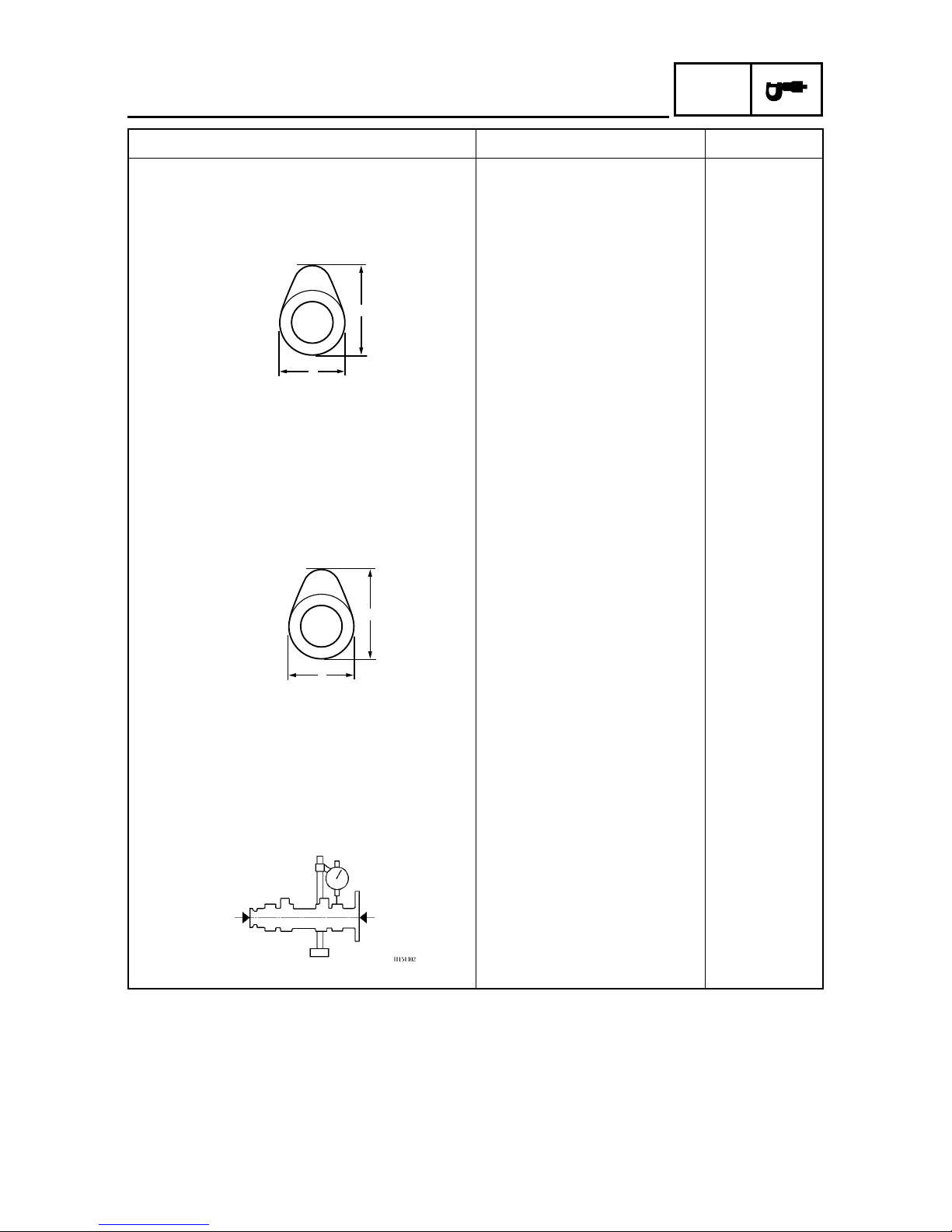
Camshaft
Drive system Chain drive (left) …
Intake camshaft lobe dimensions
Measurement A 25.267 ~ 25.367mm 25.167mm
(0.995 ~ 0.999in) (0.991in)
Measurement B 21.069 ~ 21.169mm 20.969mm
(0.829 ~ 0.833in) (0.826in)
Exhaust camshaft lobe dimensions
Measurement A 25.275 ~ 25.375mm 25.175mm
(0.995 ~ 0.999in) (0.991in)
Measurement B 21.069 ~ 21.169mm 20.969mm
(0.829 ~ 0.833in) (0.826in)
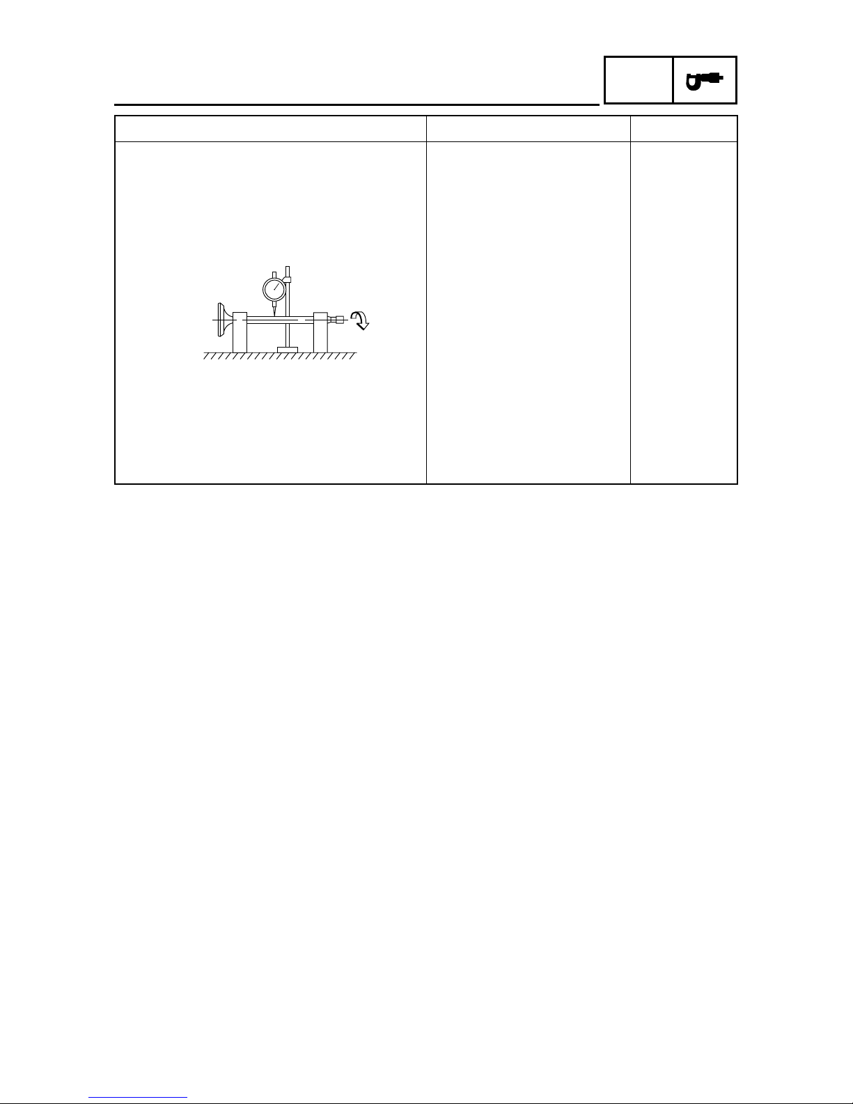
Maximum camshaft runout … 0.03mm
(0.0012in)
2-5
SPEC
Item
Standard
Limit
B
C
D
A
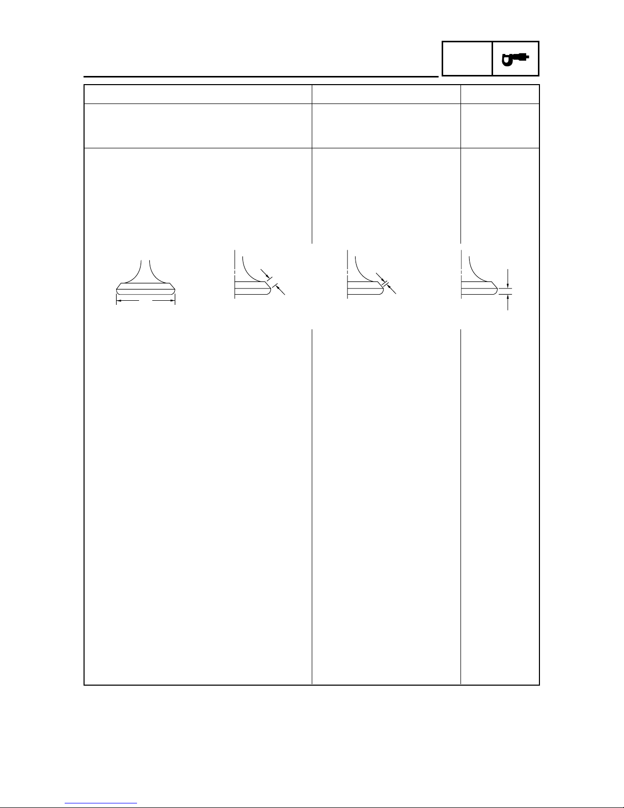
Head Diameter Face Width Seat Width Margin Thickness
ENGINE SPECIFICATIONS
Timing chain
Model/number of links Morse 92RH2005/94 …
Tensioning system Automatic …
Valve, valve seats, v alve guides
Valve clearance (cold)
Intake 0.10 ~ 0.14mm …
(0.004 ~ 0.006in)
Exhaust 0.16 ~ 0.20mm …
(0.006 ~ 0.008in)
Valve dimensions
V alv e head diameter A
Intake 18.9 ~ 19.1mm …
(0.744 ~ 0.752in)
Exhaust 16.9 ~ 17.1mm …
(0.665 ~ 0.673in)
Valve face width B
Intake 1.48 ~ 2.18mm …
(0.058 ~ 0.086in)
Exhaust 1.91 ~ 2.61mm …
(0.075 ~ 0.103in)
Valve seat width C
Intake 0.9 ~ 1.1mm (0.035 ~ 0.043in) …
Exhaust 0.9 ~ 1.1mm (0.035 ~ 0.043in) …
Valve margin thickness D
Intake 0.7mm (0.028in) …
Exhaust 1.0mm (0.039in) …
V alve stem diameter
Intake 4.970 ~ 4.985mm 4.940m m
(0.1956 ~ 0.1963in) (0.1945in)
Exhaust 4.955 ~ 4.970mm 4.925m m
(0.1951 ~ 0.1957in) (0.1939in)
V alve guide inside diameter
Intake 5.000 ~ 5.012mm 5.050m m
(0.1969 ~ 0.1973in) (0.1988in)
Exhaust 5.000 ~ 5.012mm 5.050m m
(0.1969 ~ 0.1973in) (0.1988in)
2-6
SPEC
ENGINE SPECIFICATIONS
Item
Standard
Limit
Valve stem to valve guide clearance
Intake 0.015 ~ 0.042mm 0.08mm
(0.0006 ~ 0.0017in) (0.0031in)
Exhaust 0.030 ~ 0.057mm 0.1mm
(0.0012 ~ 0.0022in) (0.0039in)
Valve stem runout … 0.01mm
(0.0004 in)
Valve seat width
Intake 0.9 ~ 1.1mm (0.035 ~ 0.043in) 1.6mm
(0.063in)
Exhaust 0.9 ~ 1.1mm (0.035 ~ 0.043in) 1.6mm
(0.063in)

2-7
SPEC
Item
Standard
Limit
ENGINE SPECIFICATIONS
Valve springs
Free length
Intake 41.88mm (1.649in) 39.786mm
(1.566in)
Exhaust 41.88mm (1.649in) 39.786mm
(1.566in)
Installed length (valve closed)
Intake 30mm (1.18in) …
Exhaust 30mm (1.18in) …
Compressed spring force (installed)
Intake 137 ~ 157N/mm …
(13.97 ~ 16.01kgf/mm,
30.83 ~ 35.33lbf/in)
Exhaust 137 ~ 157N/mm …
(13.97 ~ 16.01kgf/mm,
30.83 ~ 35.33lbf/in)
Spring tilt
Intake … 2.5°/1.8mm
(2.5°/0.07in)
Exhaust … 2.5°/1.8mm
(2.5°/0.07in)
Winding direction (top view)
Intake Clockwise …
Exhaust Clockwise …
Valve seat reformed Yes …
Cylinder
Cylinder arrangement Forward inclined …
single cylinder
Bore × stroke 52.4 × 57.9mm (2.06 × 2.28in) …
Compression ratio 10:1 …
Bore 52.40 ~ 52.41mm …
(2.0630 ~ 2.0634in)
Maximum taper … 0.05mm
(0.002in)
Maximum out-of-round … 0.05mm
(0.002in)
2-8
SPEC
Item
Standard
Limit
H
D
ENGINE SPECIFICATIONS
T
B
B
T
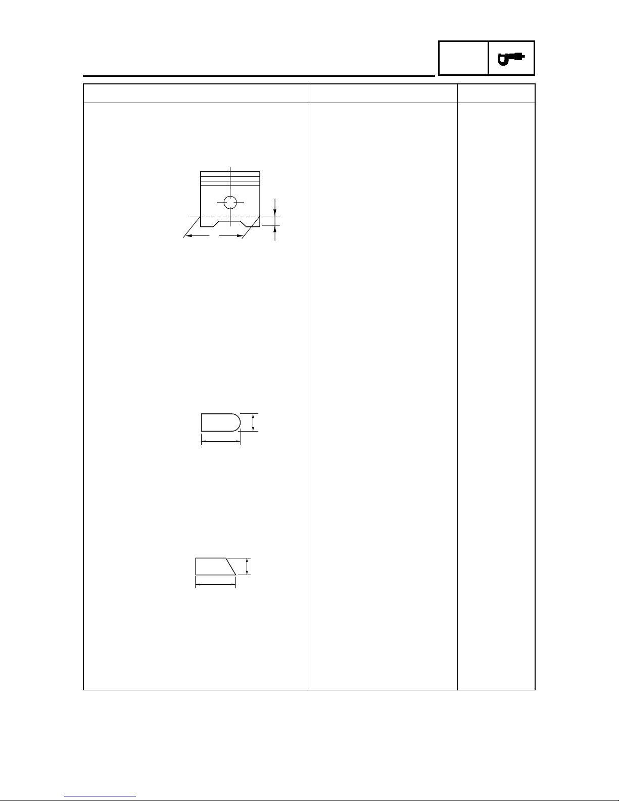
Piston
Piston-to-cylinder clearance 0.010 ~ 0.035mm 0.15mm
(0.0004 ~ 0.0014in) (0.0059in)
Diameter D 52.375 ~ 52.390mm …
(2.0620 ~ 2.0626in)
Height H 7.0mm (0.28in) …
Piston pin bore (in the piston)
Diameter 15.002 ~ 15.013mm 15.043mm
(0.5906 ~ 0.5911in) (0.5922in)
Offset 0.35 ~ 0.65mm …
(0.0138 ~ 0.0256in)
Offset direction Intake side …
Piston pin
Outside diameter 14.995 ~ 15.000mm 14.975mm
(0.5904 ~ 0.5906in) (0.5896in)
Piston rings
T op ring
Ring type Barrel …
Dimensions (B × T) 1.0 × 2.1mm …
(0.0394 × 0.0827in)
End gap (installed) 0.10 ~ 0.25mm 0.50mm
(0.0039 ~ 0.0098in) (0.0197in)
Ring side clearance 0.02 ~ 0.08mm 0.13mm
(0.0008 ~ 0.0031in) (0.0051in)
2nd ring
Ring type Taper …
Dimensions (B × T) 1.0 × 2.1mm …
(0.0394 × 0.0827in)
End gap (installed) 0.25 ~ 0.40mm 0.75mm
(0.0098 ~ 0.0157in) (0.0295in)
Ring side clearance 0.02 ~ 0.06mm 0.12mm
(0.0008 ~ 0.0024in) (0.0047in)
2-9
SPEC
ENGINE SPECIFICATIONS
Item
Standard
Limit
B
T
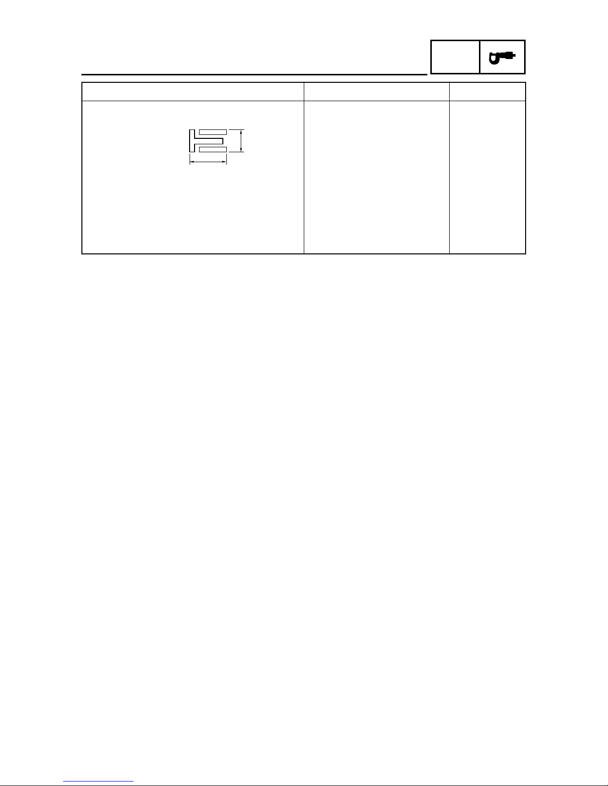
Oil ring
Dimensions (B × T) 2.0 × 2.5mm …
(0.0787 × 0.0984in)
End gap (installed) 0.2 ~ 0.7mm …
(0.0079 ~ 0.0276in)
Ring side clearance 0.04 ~ 0.12mm …
(0.0016 ~ 0.0047in)
2-10
SPEC
Item
Standard
Limit
ENGINE SPECIFICATIONS
Rocker arm/rocker arm shaft
Rocker arm inside diameter 10.000 ~ 10.015mm …
(0.3937 ~ 0.3943in)
Rocker arm shaft outside diameter 9.981 ~ 9.991mm …
(0.3930 ~ 0.3933in)
Arm-to-shaft clearance 0.009 ~ 0.034mm …
(0.0004 ~ 0.0013in)
Connecting rod
Connecting rod length 93.45 ~ 93.55mm …
(36.791 ~ 36.831in)
Small end inside diameter 15.015 ~ 15.028mm …
(0.591 ~ 0.592in)
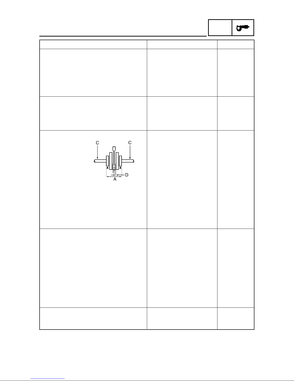
Crankshaft
Width A 45.45 ~ 45.50mm …
(1.789 ~ 1.791in)
Maximum runout C … 0.03mm
(0.0012in)
Big end side clearance D 0.15 ~ 0.45mm
(0.006 ~ 0.018in)
Big end radial clearance E 0 ~ 0.01mm (0 ~ 0.0014in) …
Clutch
Clutch type Automatic centrifugal …
Clutch shoe thickness 3.2mm ~ 3.5mm (0.13~0.14in) 2.0mm
(0.079in)
Clutch shoe spring free length 28.5mm (1.12in) …
Clutch housing inside diameter 120mm (4.72in) 120.5mm
(4.74in)
Compression spring free length 108mm (4.25in) …
Weight outside diameter 20mm (0.79in) 19.5mm
(0.77in)
Clutch-in revolution 2700 ~ 3300r/min …
Clutch-stall revolution 5150 ~ 6150r/min …
V-belt
V -belt width 22mm (0.87in) 19.8mm
(0.78in)
 Loading...