


YTD421B
APPLICATION MANUAL
IDR ISDN Driver/Receiver
YTD421B APPLICATION MANUAL
CATALOG No. : LSI-6TD421B3
1998.8
IMPORTANT NOTICE
1. Yamaha reserves the right to makechanges to its Products and to this do cument with-
out notice. The information contained in this document has b een carefully checked and
is believed to be reliable. However, Yamaha assumes no responsibilities for inaccura-
cies and makes no commitment to update or to keep current the information contained
in this document.
2. These Yamaha Pro ducts are designed only for commercial and normal industrial ap-
plications, and are not suitable for other uses, such as medical life supp ort equipment,
nuclear facilities, critical care equipmentorany other application the failure of which
could lead to death, personal injury or environmental or property damage. Use of the
Products in any such application is at the customer's sole risk and expense.
3. Yamaha assumes no liability for incidental, consequential or special damages or injury
that may result from misapplication or improper use or op eration of the Pro ducts.
4. Yamaha makes no warranty or representation that the Pro ducts are sub ject to in-
tellectual property license from Yamaha or any third party, and Yamaha makes no
warranty or representation of non-infringement with resp ect to the Pro ducts. Yamaha
specically excludes any liability to the Customer or any third party arising from or
related to the Pro ducts' infringementofany third party's intellectual property rights,
including the patent, copyright, trademark or trade secret rights of any third party.
5. Examples of use described herein are merely to indicate the characteristics and per-
formance of Yamaha pro ducts. Yamaha assumes no resp onsibility for any intellectual
property claims or other problems that may result from applications based on the ex-
amples describ ed herein. Yamaha makes no warranty with respect to the products,
express or implied, including, but not limited to the warranties of merchantability,
tness for a particular use and title.
Contents
1 INTRODUCTION 3
1.1 General Description
: : : : : : : : : : : : : : : : : : : : : : : : : : : : : : : : : : : : : : : : : :
3
1.2 Features
: : : : : : : : : : : : : : : : : : : : : : : : : : : : : : : : : : : : : : : : : : : : : : : : :
3
2 BLOCK DIAGRAM 5
2.1 YTD421B Internal Blo ck Diagram
: : : : : : : : : : : : : : : : : : : : : : : : : : : : : : : : : :
5
2.2 System Block Diagram
: : : : : : : : : : : : : : : : : : : : : : : : : : : : : : : : : : : : : : : : :
6
3 PIN DESCRIPTIONS 7
3.1 Pin Assignments
: : : : : : : : : : : : : : : : : : : : : : : : : : : : : : : : : : : : : : : : : : : :
7
3.2 Pin Functions
: : : : : : : : : : : : : : : : : : : : : : : : : : : : : : : : : : : : : : : : : : : : : :
8
3.2.1 Common Section
: : : : : : : : : : : : : : : : : : : : : : : : : : : : : : : : : : : : : : : :
8
3.2.2 Receiver Section
: : : : : : : : : : : : : : : : : : : : : : : : : : : : : : : : : : : : : : : :
8
3.2.3 Driver Section
: : : : : : : : : : : : : : : : : : : : : : : : : : : : : : : : : : : : : : : : :
9
4 FUNCTIONS 11
4.1 Receiver Section
: : : : : : : : : : : : : : : : : : : : : : : : : : : : : : : : : : : : : : : : : : : :
11
4.2 Driver Section
: : : : : : : : : : : : : : : : : : : : : : : : : : : : : : : : : : : : : : : : : : : : : :
11
4.3 Reference Source Section
: : : : : : : : : : : : : : : : : : : : : : : : : : : : : : : : : : : : : : : :
12
5 ELECTRICAL CHARACTERISTICS 13
5.1 Absolute Maximum Ratings
: : : : : : : : : : : : : : : : : : : : : : : : : : : : : : : : : : : : : :
13
5.2 Recommended Operating Conditions
: : : : : : : : : : : : : : : : : : : : : : : : : : : : : : : : :
13
5.3 DC Characteristics
: : : : : : : : : : : : : : : : : : : : : : : : : : : : : : : : : : : : : : : : : : :
14
5.4 AC Characteristics
: : : : : : : : : : : : : : : : : : : : : : : : : : : : : : : : : : : : : : : : : : :
15
5.4.1 Receiver Characteristics
: : : : : : : : : : : : : : : : : : : : : : : : : : : : : : : : : : : :
15
5.4.2 Driver Characteristics
: : : : : : : : : : : : : : : : : : : : : : : : : : : : : : : : : : : : :
16
5.4.3 Driver, Receiver I/O Imp edance
: : : : : : : : : : : : : : : : : : : : : : : : : : : : : : :
17
6 PACKAGE OUTLINE 19
APPENDIX
A EXAMPLE OF APPLICATIONS 21
A.1 Example of Application Circuits
: : : : : : : : : : : : : : : : : : : : : : : : : : : : : : : : : : :
21
1

2
CONTENTS
Chapter 1
INTRODUCTION
1.1 General Description
YTD421B (IDR) is an analog driver/receiver LSI for the ISDN BRI S/T interface. Since YTD421B can
be used on both TE (Terminal Equipment) side and NT (Network Termination) side, with connecting TTL
interface LSI for TE (YTD418 or YTD423B), or that for DSU (YTD426B), eachchip set allows layer 1 function
conforming to ITU-T Recommendation I.430.
1.2 Features
1. Compatible with ITU-T Recommendation I.430 [1992 edition] and TTC Standard JT-I430 [1993 edition]
2. Connects directly to the Yamaha YTD418, YTD423B or YTD426B using TTL interface
3. Allows direct connection to +3.3 volt supply operation LSI(YTD418C)
4. Neither external relay nor common mo de choke is required
5. 1:2 pulse transformer interface
6. Lowpower consumption
7. CMOS technology
8. 20-pin SSOP
9. Operates on single +5 volt supply
3

4
CHAPTER 1. INTRODUCTION
Chapter 2
BLOCK DIAGRAM
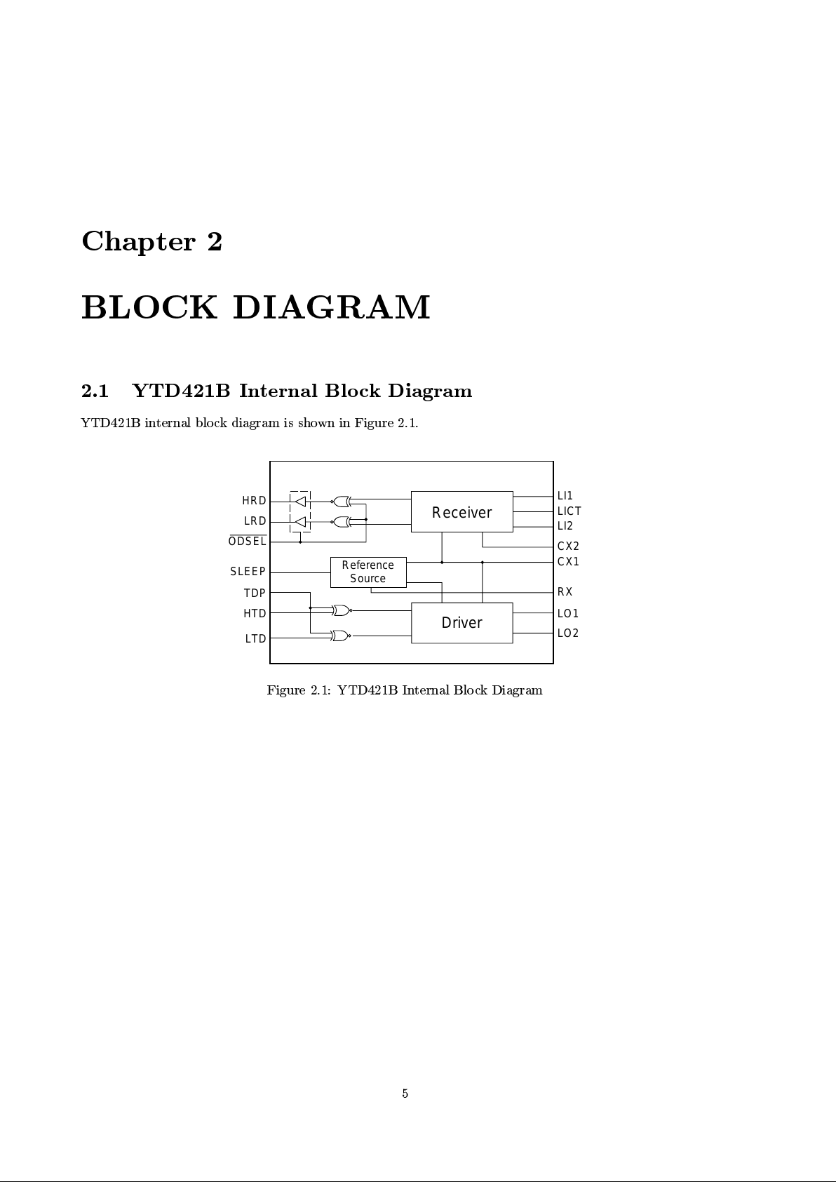
2.1 YTD421B Internal Blo ck Diagram
YTD421B internal blo ck diagram is shown in Figure 2.1.
Receiver
Driver
Reference
Source
LI1
LICT
LI2
CX2
CX1
RX
LO1
LO2
HTD
LTD
TDP
SLEEP
ODSEL
HRD
LRD
Figure 2.1: YTD421B Internal Block Diagram
5

6
CHAPTER 2. BLOCK DIAGRAM
2.2 System Blo ck Diagram
YTD421B can be used as the ISDN BRI S/T interface driver/receiver on both TE side and NT side. Some
examples of the system blo ck diagram using YTD421B are shown in Figure 2.2 and Figure 2.3.
YTD418
or
YTD423B
YTD421B
(TE side)
YTD421B
(NT side)
DSUTerminal Adapter with S/T interface
YTD425
S/T U
RS232
YTD426B
and
YTD427
Figure 2.2: Example 1 : Terminal Adapter with S/T Interface and NT1
YTD418
or
YTD423B
YTD421B
(NT side)
YTD425
S/T
U
RS232
YTD426B
and
YTD427
Terminal Adapter with U interface
Figure 2.3: Example 2 : Terminal Adapter with U Interface
 Loading...