

CONTENTS
GENERAL
PERIODIC INSPECTIONS
ADJUSTMENTS
ENGINE
CARBURETION
INFORMATION
OVERHAUL
AND
CHASSIS
ELECTRICAL
APPENDICES

CHAPTER
1.
GENERAL INFORMATION
MACHINE
Frame serial
Engine
(
SPECIAL
For
For
For
For
Additional
IDENTIFICATION
number
serial
TOOLS
tune-up
engine
chassis
electrical
number
........................................................
.........................................................
service
service
components
tools
and
..............................................
..................................................
.................................................
.....................•..............................
...................................................
.............................................
supplies
..........................................
1-1
1-1
1-1
1-2
1-2
1-2
1-3
1-4
1-4
GENERAL
INFORMATION
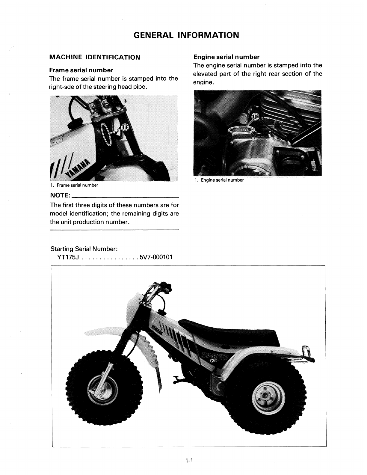
MACHINE
Frame serial
The frame serial number is stamped into the
right-sde
1. Frame serial number
NOTE:
The first three digits
model identification; the remaining digits are
the unit production number.
IDENTIFICATION
number
of
the steering head pipe.
______________________
of
these numbers are
__
for
Engine serial
The engine serial number is stamped into the
elevated part
engine.
number
of
the right rear section
of
the
Starting Serial Number:
YT175J
................
5V7-000101
1-1

SPECIAL TOOLS
The proper special tools
complete and accurate
assembly. Using the correct special tool will
help prevent damage caused by the
improper tools or improvised techniques.
Fortune-up
1.
Timing light
2.
Tachometer
For
engine
1.
Dial gauge
service
are
necessary
tune-up
use
for
and
of
PIN 90890-03002-00
Tools
timing.
1,
2,
and 3
4.
Crankcase separation tool
are
PIN 90890-01135-00
use
to
set the ignition
2.
Dial gauge stand
PIN 90890-01256-00
This tool is use
as
remove the crankshaft from either case.
5.
Crank installer
to
split the crankcase
pot
PIN 90890-01275-00
6.
Crank installer bolt
PIN 90890-01275-00
as
well
3.
Dial gauge needle
PIN 90890-03099-00
1-2

7. Spacer
PIN
90890-01288-00
8. Crank installer bolt adapter
PIN
90890-01278-00
10.
Flywheel holding tool
PIN
90890-01235-00
Use
this tool
to
hold the flywheel magneto
while removing or tightening the flywheel
magneto securing nut.
For
chassis
1.
Steering
PIN
service
nut
wrench
90890-01051-00
Tools
5,
crankshaft.
9.
Flywheel puller
PIN
This tool
magneto.
6,
7, and 8 are
90890-01189-00
is
use
to
remove the flywheel
use
to
install the
Use
this wrench
to
put the proper tension on
the steering head bearing.
2. Front-fork-cylinder holder
PIN
90890-01300-00
to
This tool is used
loosen and tighten the
front fork cylinder holding bolt.
1-3
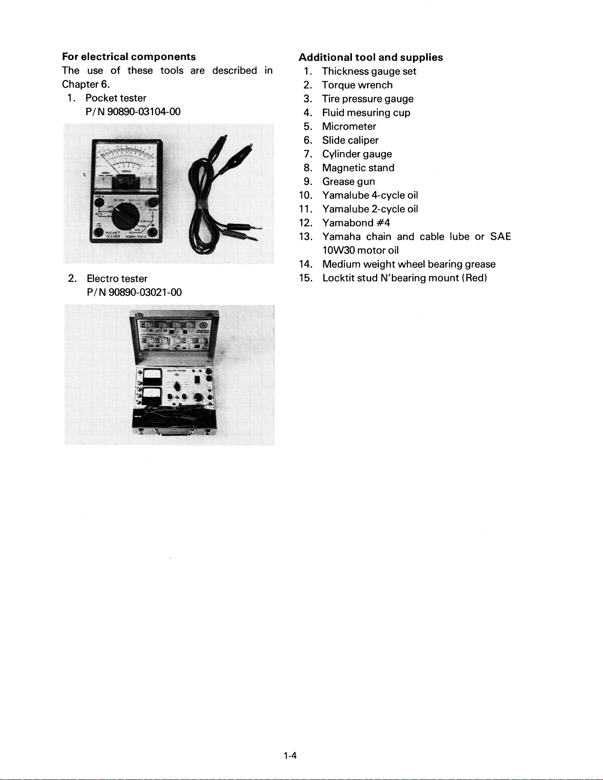
For
electrical
The
use
of
these tools
Chapter
6.
1 . Pocket tester
PIN
90890-03104-00
2. Electro tester
PIN
90890-03021-00
components
are
described in
Additional
1.
Thickness gauge set
tool
and
supplies
2. Torque wrench
3.
Tire pressure gauge
4. Fluid mesuring cup
5.
Micrometer
6. Slide caliper
7. Cylinder gauge
8. Magnetic stand
9.
Grease gun
10.
Yamalube 4-cycle oil
11.
Yamalube 2-cycle oil
12. Yamabond
#4
13. Yamaha chain and cable lube or SAE
10W30
14. Medium
motor
weight
oil
wheel bearing grease
15. Locktit stud N'bearing mount (Red)
1-4

CHAPTER
2.
PERIODIC INSPECTIONS
INTRODUCTION
MAINTENANCE
ENGINE
................................................................
Spark
Fuel
Over
Idle
Throttle
Throttle
Autolube
Minimum
Air
Engine
Checking
Transmission
Checking
plug
line
............................................................
flow
chamber
speed
cable
lever
pump
pump
bleeding
oil
....................................
the
ignition
AND
.........................................................
INTERVALS
..........................................................
...................................................
..........................................................
........................................................
........................................................
cable
stroke
.........................................................
water
oil
release
.....................................................
timing
CHART
adjustment
check
valve
..............................................
......................................
......................................
and
adjustment
.......................................
............................
ADJUSTMENTS
'.'
.....................
2-1
2-1
2-3
2-3
2-3
2-3
2-3
2-3
2-4
2-4
2-4
2-5
2-6
2-6
2-6
2-7
CHASSIS
ELECTRICAL
...............................................................
Air
cleaner
Front
Rear
brake
brake
Brake
Drive
Drive
Drive
Steering
Wheel
Fuel
Tires
Cable
Brake
Headlight
Headlight
adjustment
chain
chain
chain
bearings
cock
..............................................................
inspection
and
..........................................................
shoe
inspection
pad
inspection
....................................................
tension
tension
cleaning
head
..........................................................
change
...........................................................
bulb
beam
check
adjustment
and
adjustment
.....................................................
and
lubrication
pedals/front
replacement
adjustment
...........................................
.............................................
............................................
........................................
lubrication
............................................
..........................................
..........................................
...................................
......................................
and
rear
brake
levers
.....................
2-8
2-8
2-8
2-8
2-9
2-11
2-11
2-11
2-11
2-12
2-13
2-13
2-14
2-14
2-15
2-15
2-15
PERIODIC INSPECTIONS
INTRODUCTION
AND
ADJUSTMENTS
This chapter includes
all
information necessary to perform recommended inspections and adjustments. These preventive maintenance procedures, if followed, will ensure more reliable vehicle operation and a longer service life. The need for costly overhaul work will be greatly reduced.
This information applies to vehicles already
in
service and to
new
vehicles that are being
prepared for sale. All service technicians should be familiar with this entire chapter.
MAINTENANCE
The following charts should be considered strictly
tion intervals. You must take into consideration
a variety
quirements.
all
of
individual uses. This time schedule should be altered
For
parts must be lubricated much more frequently that shown on the chart to avoid damage
INTERVALS CHARTS
example, if the machine
as
a guide
~hat
weather, terrain, geographical location, and
is
continually operated
to
general maintenance and lubrica-
to
match individual owner's re-
in
an
area
of
high humidity, then
caused by water to metal parts.
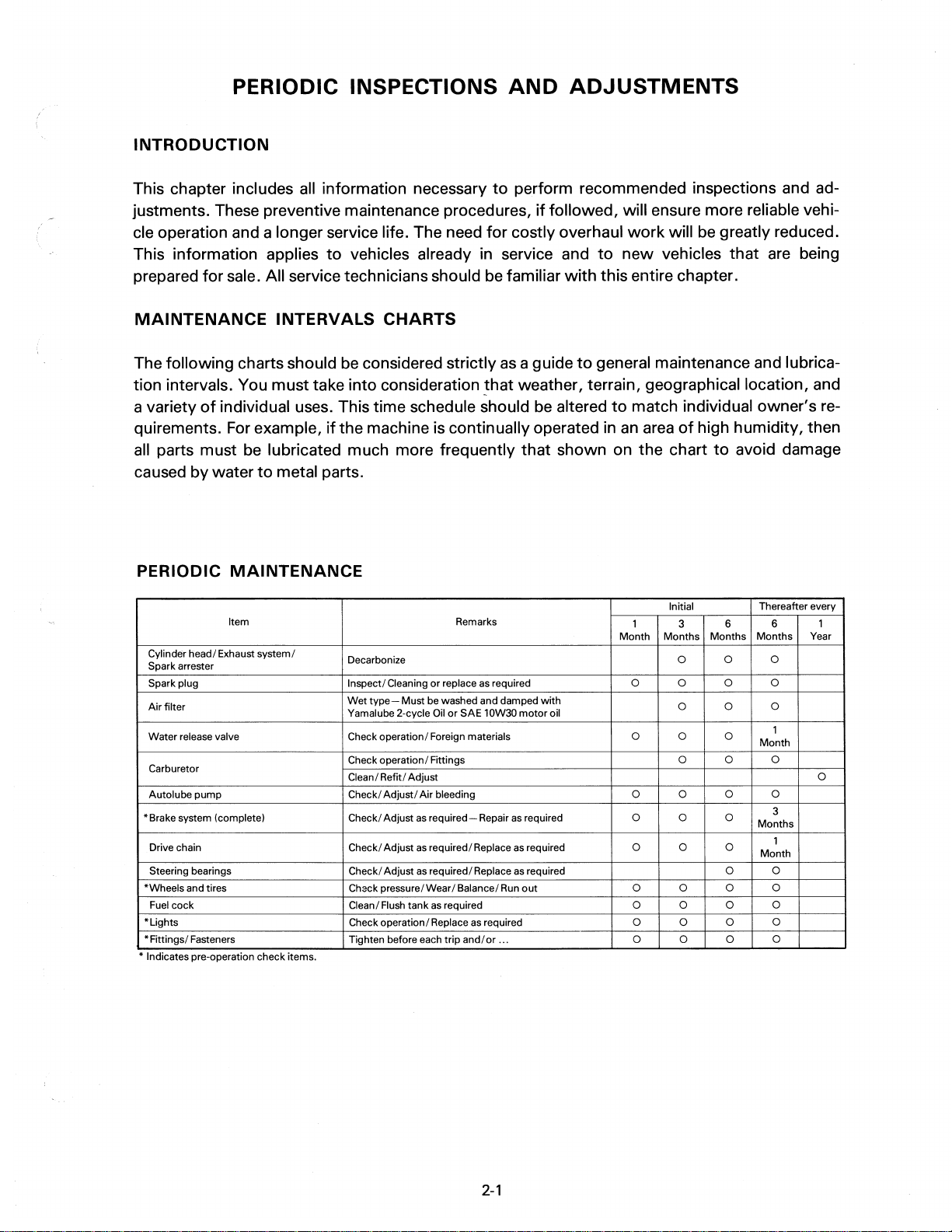
PERIODIC
Cylinder head/ Exhaust
Spark arrester
Spark plug Inspect/ Cleaning
Air
filter
Water
release valve Check operation/ Foreign materials
Carburetor
Autolube
'Brake
system (complete)
Drive chain Check/ Adjust
Steering bearings
'Wheels
Fuel cock
"Lights
'Fittings/
• Indicates pre-operation check Items.
MAINTENANCE
Item Remarks
system/
pump
and tires Chack pressure/Wear/ Balance/
Fasteners Tighten before each
Decarbonize
or
replace
Wet
type-
Yamalube 2-cycle
Check operation/ Fittings
Clean/ Refit/ Adjust
Check/
Check/ Adjust
Check/ Adjust
Clean/ Flush tank
Check operation/Replace
Must be washed and damped
Oil
or
Adjust/
Air
bleeding 0 0 0
as
required-Repair
as
required/ Replace
as
required/ Replace
as
required 0 0
trip
as
SAE 10W30
as
required 0 0 0
and/or
Initial
1
Month
required 0 0 0
with
motor
oil
as
required
as
required 0 0 0
as
required
Run
out
... 0 0 0
3 6
Months
Months
0 0 0
0 0
0
0
0 0 0
0
0
0 0 0
Thereafter every
Months Year
0
Month
0
Months
Month
0 0
0 0
6
0
0
0
0
0
0
1
1
0
3
1
2-1
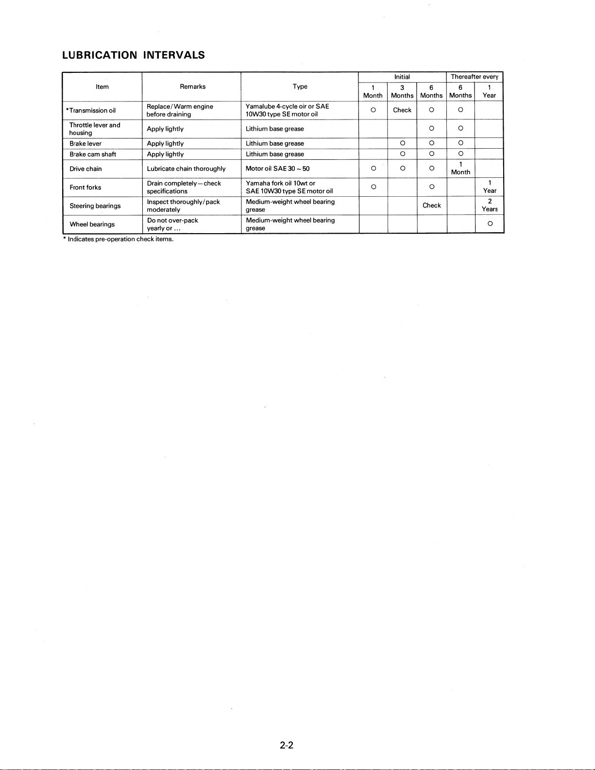
LUBRICATION INTERVALS
Item Remarks Type
"Transmission oil
Throttle lever and
housing
Brake lever
Brake cam shaft
Drive chain Lubricate chain thoroughly
Front forks
Steering bearings
Wheel bearings
" Indicates pre-operation check Items.
Replace/Warm engine Yamalube 4-cycle oir
before draining
Apply lightly
Apply
lightly
Apply
lightly
Drain
completely-check
specifications SAE 10W30 type
Inspect
thoroughly/pack
moderately grease
Do
not
over-pack Medium-weight wheel bearing
yearly
or
...
Initial Thereafter every
1
Month
Months
or
OW30
type
1
Lithium base grease
Lithium base grease
Lithium base grease 0
Motor
Yamaha
Medium-weight wheel bearing
grease
SE
oil SAE 30 - 50 0 0 0
fork
oil10wt
motor
SE
SAE
oil
or
motor
oil
0 Check
0 0
3 6
Months
0
Check
Months
0
0
0 0
0
Month
6 1
Year
0
0
0
1
Year
Years
1
2
0
2-2

ENGINE
Spark
plug
1.
Check electrode condition and wear, insulator color, and electrode gap.
2.
Clean the spark plug
if
cleaner
to
adjust the plug gap
necessary.
with
spark plug
Use
a wire gauge
to
the specifica-
tion.
3.
If
the electrode becomes
too
worn
replace the spark plug.
4. When installing the plug, always clean
the gasket surface, wipe
off
any grime
that might be rresent on the surface
the spark plug, and torque the spark
plug properly.
of
Air screw (Turns out): 1 and
2.
Start the engine and let
3.
Throttle stop screw
Turn throttle stop screw in or
achieve smooth engine operation at
specified idle speed.
±
50
,
Idling speed: 1,600
NOTE:
______________________
r/min
The pilot air and throttle stop screws
separate adjustments
justed at the same time
but
they must be ad-
to
achieve optimum
operating condition at engine idle speeds.
1/4
it
warm up.
out
to
__
are
Standard spark plug: NGK
BP7ES
Spark plug gap:
0.031
0.7 - 0.8 mm (0.028 -
in)
Spark plug tightening torque:
20Nm(2.0m·kg,14.5ft·lb)
Fuel
line
Check the fuel hoses and vacuum lines for
if
cracks or damage; replace
Over
flow
chamber
If gasoline begin
to
show
loosen the three screws from over
necessary.
up in the pipe
II
A"
flow
chamber and completely drain gasoline from
the pipe
II
A"
and chamber.
2.
Pilot air screw
nut
(at
,
1.
Throttle stop screw
Throttle
cable
Loosen cable adjuster lock
buretor) and turn cable adjuster until
specified free play is obtained. Retighten lock
nut.
Free
play: 1
-1.5
mm
(0.04 - 0.06 in)
top
of
car-
Idle
speed
1.
Turn the pilot air screw until
it
seats, then back
out
This adjustment can be made
engine stopped.
it
to
specification.
lightly
with
2-3
1.
Adjuster
2.
Lock
nut

Throttle
Loosen the lock
lever
nut
and turn the adjuster until there is the specified free play at throttle
lever.
1.
Adjuster
2.
Lock nut
Throttle lever play:
3
-5
mm
(0.12
-0.2
in)
Autolube
pump
cable
adjustment
Before adjusting the pump cable, adjust the
throttle cable free play.
1.
Adjust the throttle cable free play
of
1 -
1.5 mm (0.04 - 0.06 in) at the cable ad-
juster on the carburetor.
2. Close the throttle lever completely, then
check
plunger pin is aligned
the Autolube pump pulley.
to
see
that
the Autolube pump
with
the mark on
3.
If
the mark and pin are
not
in alignment,
loosen the cable length adjuster lock nut
on
top
of
crankcase cover and adjust
cable length until alignment is achieved.
4. Tighten adjuster lock nut.
1.
Cable
adjuster
Minimum
pump
justment
1.
While running the engine idle, observe
the pump adjust plate carefully, and
stop the engine the moment
just plate moves
2. Measure the gap
gauge between the raised boss on
pump adjust pulley and the adjust plate.
2. Lock nut
stroke
out
to
with
check
that
the limit.
the thickness
and
the ad-
ad-
the
Match mark: 0
1.
Oil
pump
2.
Pump cable
3. Adjust pulley
4.
Match mark
5.
Guide pin
1.
Adjust plate 2. Adjust pulley
3. Repeat steps
times. When the gap measured is the
largest,
be
2-4
a.
the
pump stroke is considered
at a minimum.
3.
Thickness gauge
and b. above a
few
to

NOTE:
When inserting the thickness gauge between
the adjusting plate and the adjusting pulley,
be
is
the thickness gauge into the gap.
______________________
careful so
not
Minimum pump stroke:
0.20 - 0.25
4. If clearance
adjust plate lock
plate.
5.
Remove or add an adjust shim
quired.
that
moved.
either the plate or the pulley
In
other words, do
mm
(0.008 - 0.010 in)
is
not
correct, remove the
nut
__
not
force
and the adjust
as
re-
1.
Remove the pump cover and remove
the bleed screw.
1.
Bleed screw
2. Keep the oil running
disappear~
NOTE:
________________________
out
until air bubbles
_
1.
Adjust shim
NOTE:
Thicken shims increase pump stroke and output,
output.
Air
The Autolube Pump and delivery lines must
be
________________________
thinner shims decrease pump stroke and
bleeding
bled on the following occasions:
• Whenever the Autolube tank has run
dry.
of
• Whenever any portion
system
• If the machine lies on its side after falling
over.
is
disconnected.
the Autolube
_
Check the bleed screw gasket, and
ed, replace
3.
When air bubbles are expelled completely, tighten the bleed screw and install
the
4.
Start the engine, pull the pump wire
the
maximum.
NOTE:
It is difficult
with
ly
therefore the pump stroke should
maximum.
with a new
pump
way
cover.
out
one.
to
set the pump stroke
________________________
to
bleed the distributor complete-
the
pump stroke at a minimum, and
if
damag-
be
set
to
to
all
a
_
a
5. Keep the engine running at about 2,000
r/min
distributor and delivery pipe can
pletely bled.
2-5
for
two
minutes or so, and both
be
com-

Engine
1.
oil
Place the machine on a level place and
start the engine.
Engine oil:
Yamalube 2-cycle oil or
Air-cooled 2-stroke engine oil
Oil
tank capacity:
1.3 L
(1.1
Imp
qt,
1.4 US qt)
Checking
Before starting
valve
the
water
off,
be
is
closed. Before cleaning the air
cleaner element, check
the element case.
release
sure
if
valve
to
check that the
there is impurities in
1.
Oil
tank filler cap
NOTE:
______________________
Install the oil tank filler cap and push
into the filler.
PUSH PUSH
2. Oil warning indicator light
is
When the engine oil level
proper:
The oil warning light keeps going on
about
temperatures) -
15
seconds
40
seconds (under
(under
temperatures) after the engine has
started, and then goes
When the engine oil level
off.
is
low:
The light keeps going on after the
engine has started.
If
the light bulb is burnt out:
The light will
not
come on after the
engine has started.
it
__
fully
high
low
Transmission
oil
Recommended oil:
Yamalube 4-cycle oil or
SAE 10W30
1.
Filler cap
SE
Transmission oil capacity:
Periodic oil change: 0.7 - 0.8 L
(0.6 - 0.7 Imp qt, 0.7 - 0.8 US qt)
Total: 0.8
-0.9
(0.7 - 0.81mp qt, 0.8
Transmission drain plug torque:
20
Nm (2.0 m
2-6
·kg,
motor
2. Drain plug
L
14.5ft
oil
-1.0
·Ib)
US qt)
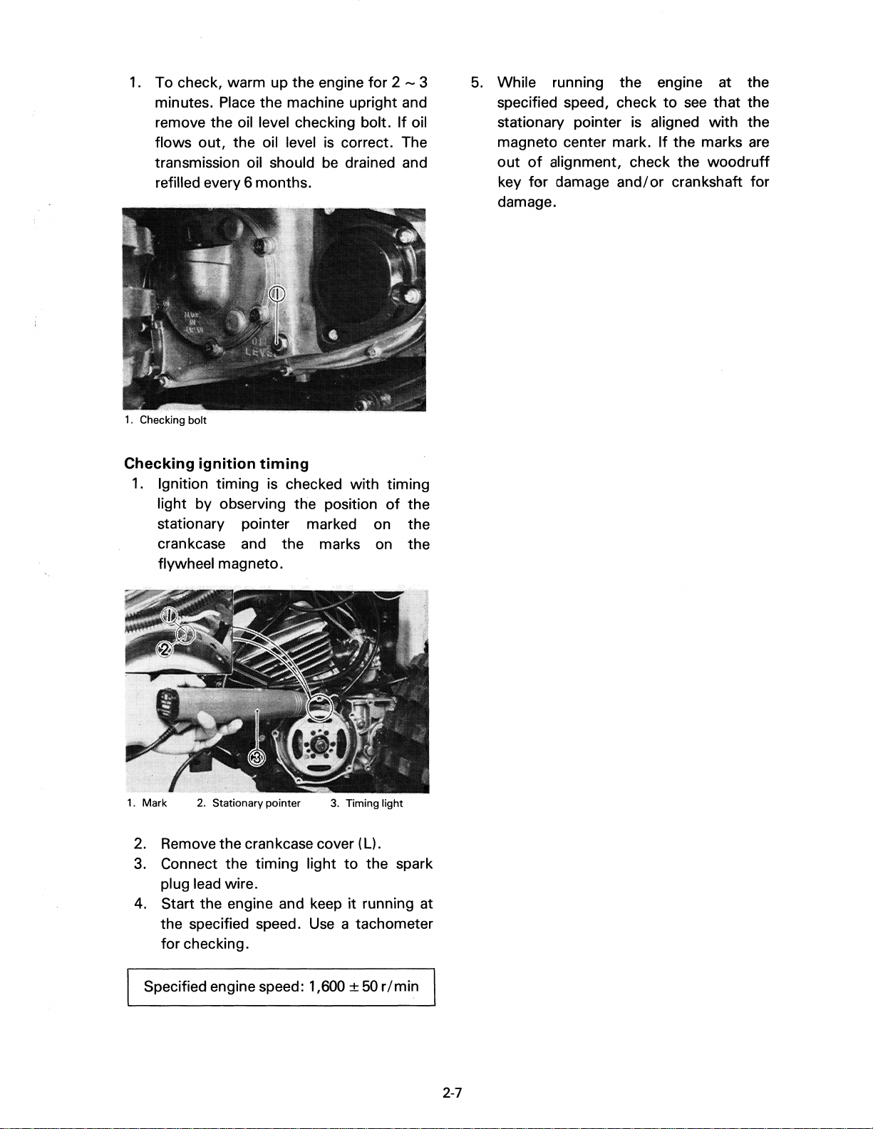
1.
To check, warm up the engine for 2 - 3
minutes. Place the machine upright and
remove the oil level checking bolt.
flows out, the oil level
transmission oil should
is
correct. The
be
drained and
refilled every 6 months.
1.
Checking bolt
If
oil
5.
While running the engine at the
specified speed, check
to
see
stationary pointer is aligned with
magneto center mark.
out
of
alignment, check the
key
for
damage
and/or
If
the marks
woodruff
crankshaft for
damage.
that
the
the
are
Checking ignition
1.
Ignition timing is checked with timing
timing
light by observing the position
stationary pointer marked on the
crankcase and the marks on the
flywheel magneto.
1.
Mark 2. Stationary pointer
2.
Remove the crankcase cover (Ll.
3.
Connect the timing light
3.
Timing light
to
plug lead wire.
4. Start the engine and keep
the specified speed.
for
checking.
it
Use
a tachometer
of
the
the spark
running at
Specified engine speed: 1,600
±
50
r / min
2-7

CHASSIS
Air
cleaner
1.
Remove the air cleaner case cap and ele-
ment assembly.
2. Wash
the
thoroughly,
3. Squeeze excess solvent
element
in
solvent.
gently,
out
and dry.
4. Pour
10W
CI
small quantity
30)
onto cleaner element and
of
motor oil (SAE
thoroughly into the porous foam
material. Element must
not
but
dripping.
be
damp with oil
of
element
but
work
cleaner
This
causing
damage.
the
buretor
element
will
allow
rapid
Additionally,
cleaner
jetting
performance
engine
removed.
unfiltered
wear
and
element
with
and
with
air
to
possible
operation
will
affect
subsequent
possible
the
air
enter,
engine
without
car-
poor
engine
overheating.
Front
brake
shoe
inspection
To check, examine the wear indicator position while depressing the brake pedal. If the
indicator reaches
to
the wear limit line,
replace the shoes.
5.
Re-install the element assembly and
case cover.
NOTE:
Each
performed, check the air inlet
case
joint rubber
fittings
thoroughly
______________________
time cleaner element maintenance is
to
of
obstructions. Check the air cleaner
to
the carburetor and manifold
for
an
air-tight seal. Tighten all fittings
to
avoid the possibility
filtered air entering the engine.
__
the cleaner
of
un-
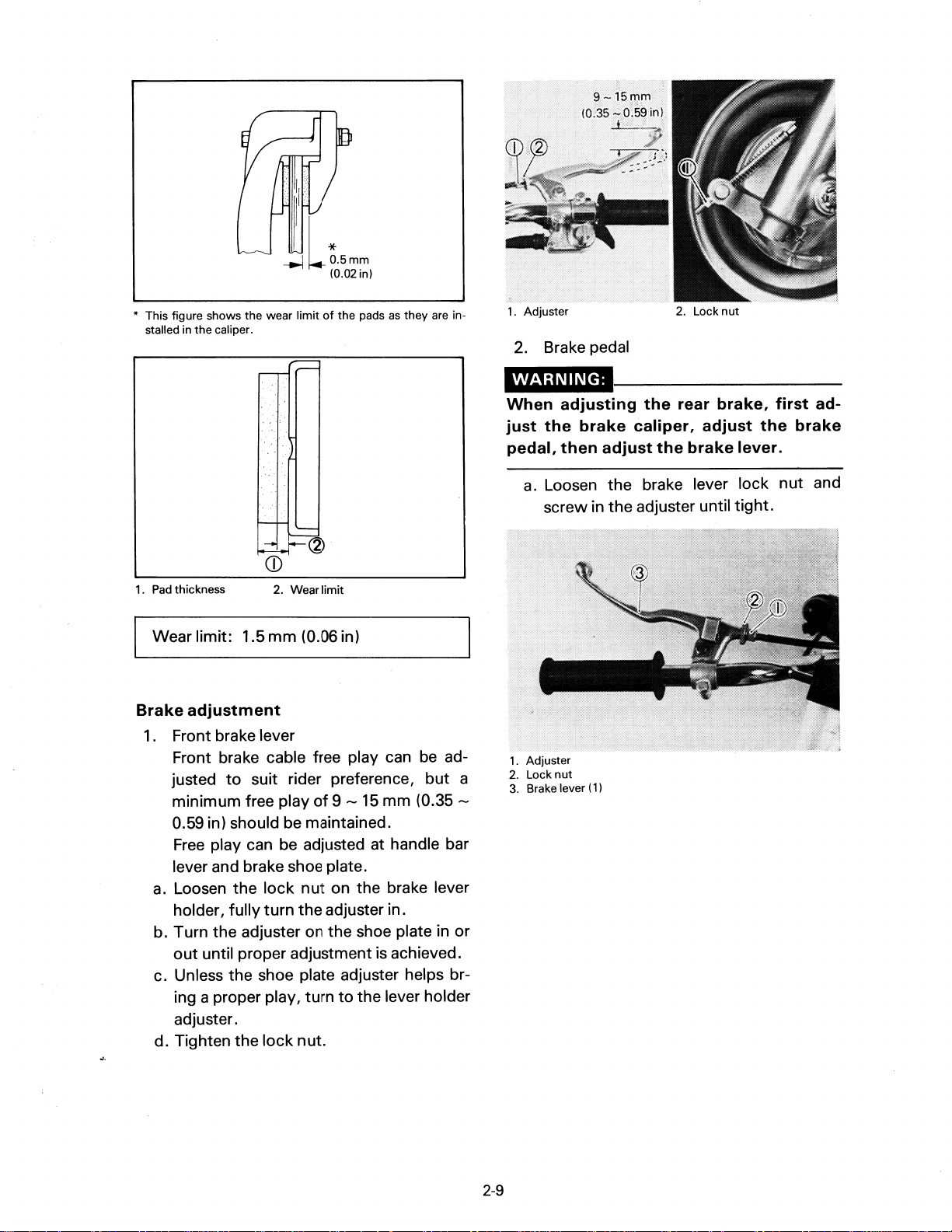
Rear
Check
brake
to
see
pad
inspection
that
the brake operates correctIy. Remove the disc cover, check the brake
pads
for
damage and wear.
If
the thickness is
less than the specified value, replace the pad
as
a set.
2-8
::
I
/1
~L~5mm
* This figure shows the wear limit
stalled in the caliper.
1.
Pad
thickness
Wear limit: 1.5
Brake
adjustment
1.
Front brake lever
Front brake cable free play can
justed
to
minimum free play
2. Wear limit
mm
suit rider preference,
(0.02 in)
of
the pads
(0.06 in)
of
9
-15
as
they
mm
be
(0.35-
0.59 in) should be maintained.
Free
play can be adjusted at handle bar
lever and brake shoe plate.
a.
Loosen the lock
nut
on the brake lever
holder, fully turn the adjuster in.
b. Turn the adjuster on the shoe plate in or
out
until proper adjustment is achieved.
c. Unless the shoe plate adjuster helps br-
ing a proper play, turn
to
the lever holder
adjuster.
d. Tighten the lock nut.
are
but
in-
ad-
a
2.
Lock
1.
Adjuster
2.
Brake pedal
nut
WARNING:
When
just
pedal,
1.
2.
3.
adjusting
the
brake
then
a.
Loosen the brake lever lock nut and
screw in
Adjuster
Lock
nut
Brakelever(l)
the
rear
caliper,
adjust
the
the
brake
adjuster until tight.
brake,
adjust
lever.
first
the
ad-
brake
2-9
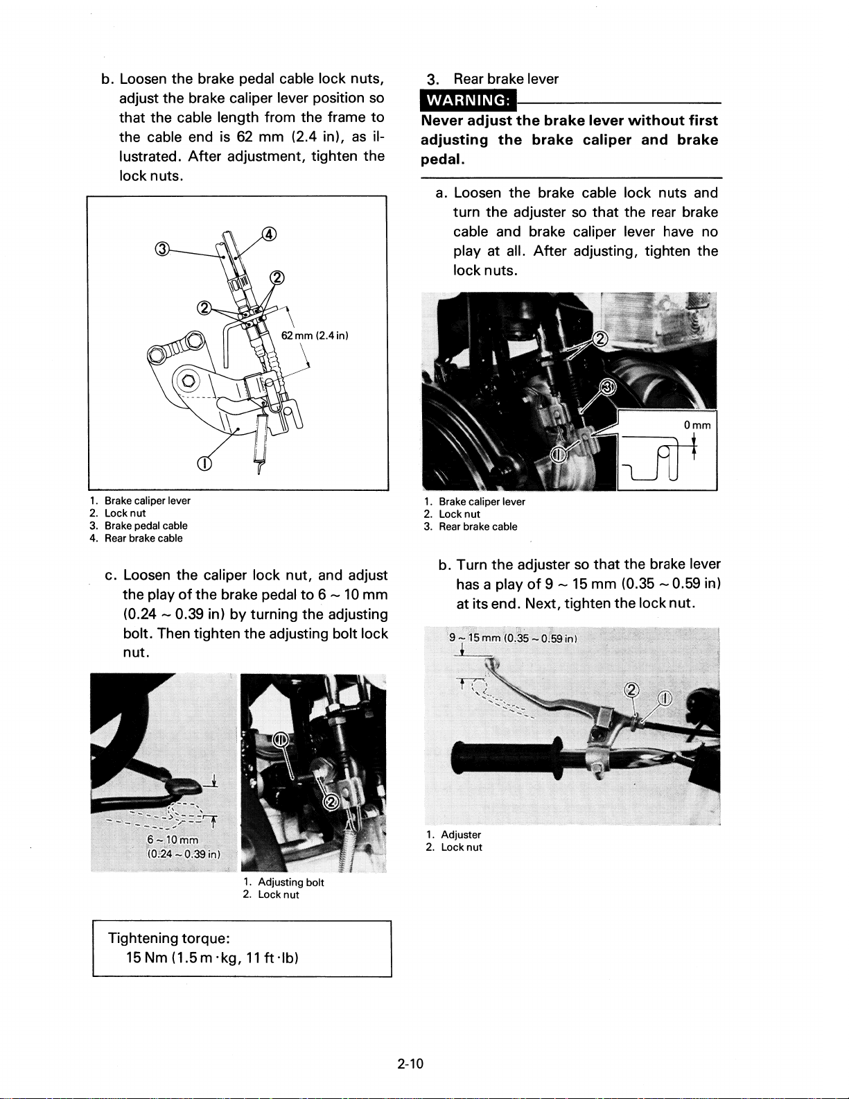
b. Loosen the brake pedal cable lock nuts,
adjust the brake caliper lever position so
that the cable length from the frame
the cable end is
lustrated.
After
62
mm (2.4 in),
as
adjustment, tighten the
lock nuts.
1.
Brake caliper lever
2.
Locknut
3.
Brake pedal cable
4.
Rear
brake cable
to
il-
3.
Rear
brake lever
WARNING:
Never
adjusting
adjust
the
the
brake
brake
lever
caliper
without
and
pedal.
a.
Loosen the brake cable lock nuts and
that
turn the adjuster so
the rear brake
cable and brake caliper lever have no
play at all.
After
adjusting, tighten the
lock nuts.
~
1.
Brake caliper lever
2.
Lock nut
3.
Rear
brake cable
first
brake
Omm
c. Loosen the caliper lock nut, and adjust
of
the play
the brake pedal
(0.24 - 0.39 in)
by
turning the adjusting
to
6 -
10
mm
bolt. Then tighten the adjusting bolt lock
nut.
1.
Adjusting bolt
2.
Lock nut
Tightening torque:
15
Nm (1.5 m
'kg,
11
ft
'Ib)
b. Turn the adjuster so
of
has a play
9 -
15
that
the brake lever
mm
(0.35 - 0.59 in)
at its end. Next, tighten the lock nut.
1.
Adjuster
2.
Locknut
2-10

Drive
chain
Inspect the drive chain with both tires
touching the ground. Check the tension at
the position shown in the illustration. The
normal vertical deflection is approximately 5
-
10
mm
ceeds
sion.
5-10mm
(0.2 - 0.4 in)
1.
Inspection
tension
(0.2 - 0.4 in).
10
mm
(0.4 in), adjust the chain ten-
window
check
If
the deflection ex-
3. Tighten
Tightening torque:
46 Nm (4.6 m ·kg,
Drive
This machine has a drive chain
rubber O-rings between the chain plates.
Steam cleaning, high-pressure washes, and
certain solvent can damage these O-rings.
Use
Wipe
SAE
lubricants on the drive chain. They may con-
tain solvents
chain
only kerosene
it
30 -50
the
rear wheel hub bolts.
33
ft-lb)
cleaning
dry, and thoroughly lubricate
motor
that
and
lubrication
with
to
clean the drive chain.
oil. Do
could damage the O-rings.
not
use any other
small
it
with
Drive
chain
1.
Loosen the rear wheel hub bolts.
2. Next, adjust chain play
by turning the chain puller adjuster.
tension
adjustment
to
specification
O-RING
D
Steering
The steering assembly should be checked
periodically
1.
2.
head
adjustment
for
looseness.
Raise
the
front
end
of
the machine so
that
there is no weight on the
wheel.
Grasp
the
bottom
rock the
forward, checking for looseness in the
steering assembly bearings.
fork
of
the forks and gently
assembly backward and
front
1.
Adjuster
2-11
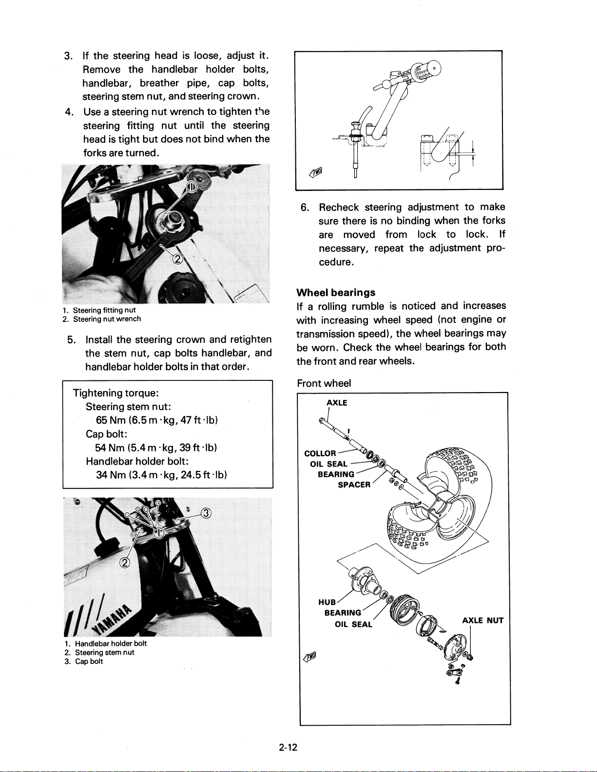
3.
If
the steering head is loose, adjust
Remove the handlebar holder bolts
handlebar, breather pipe, cap bolts,
steering stem nut, and steering crown.
Use
4.
a steering
steering fitting
head
is
forks
are
tight
nut
wrench
nut
to
tighten
until the steering
but does not bind when the
turned.
it.
t'1e
,
6.
Recheck steering adjustment
to
make
sure there is no binding when the forks
are moved from lock
to
lock.
If
necessary, repeat the adjustment procedure.
1.
Steering fitting nut
2.
Steering
5.
nut
wrench
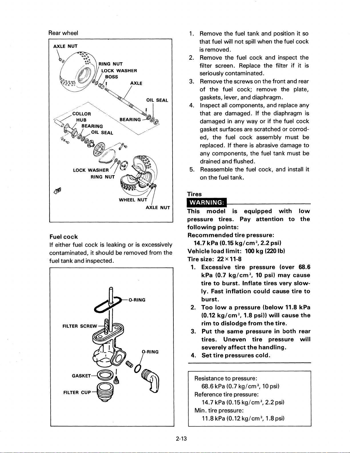
Install the steering crown and retighten
the stem nut, cap bolts handlebar, and
handlebar holder bolts
in
that order.
Tightening torque:
Steering stem nut:
65
Nm (6.5 m . kg,
Cap
bolt:
54
Nm (5.4
m'
kg,
47
39
ft-lb)
ft
'Ib)
Handlebar holder bolt:
34 Nm (3.4
m'
kg, 24.5
ft
'Ib)
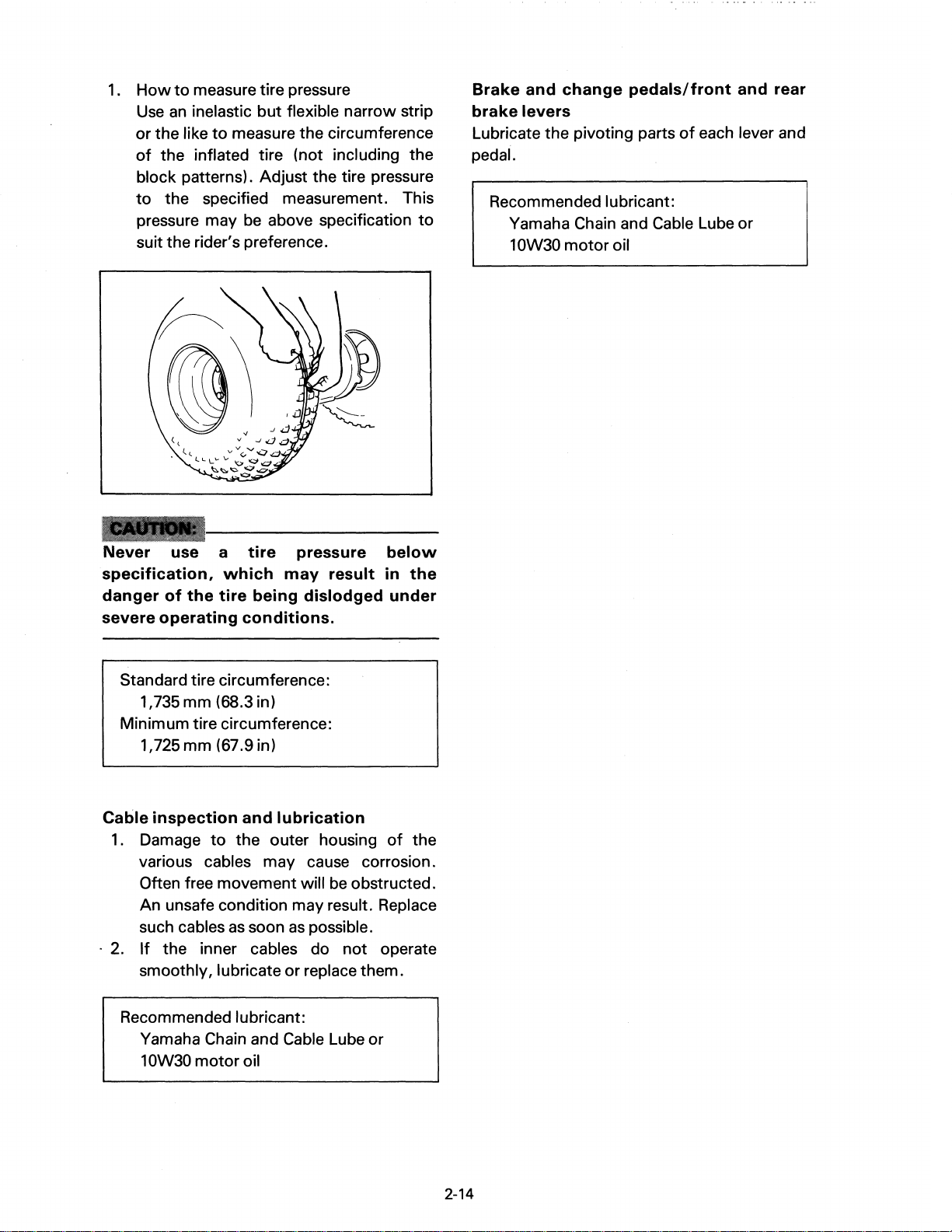
Wheel
bearings
If a rolling rumble is noticed and increases
with increasing wheel speed (not engine or
transmission speed), the wheel bearings may
be worn. Check the wheel bearings for both
front
the
and rear wheels.
Front wheel
AXLE
.{~
COLLORA~
OILSEAL~
BEARING
SPACER /
~
@~~
\ .
c:;
.
~
/
1.
Handlebar holder bolt
2.
Steering stem
3.
Cap
bolt
nut
2-12
BEARING
OIL SEAL
~
..
I
AXLE
NUT
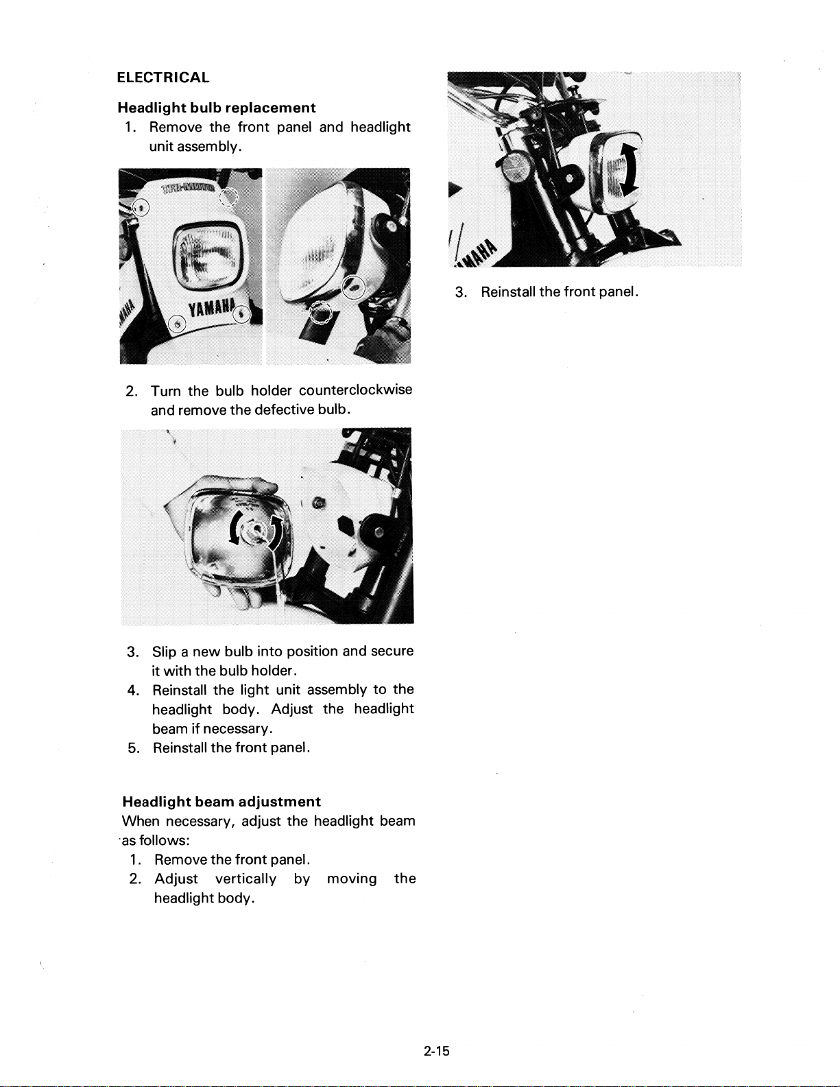
Rear
wheel
AXLE
NUT
......
\
@
t.
•
aj.,:,g'g
......
.....
":,':,0
RING NUT
@)/
":.~~:ASHER
~4.,
/~~~.
<;:::/
~N.
HUB
BEARING /
.-;.~f(t:+'~
@"
~@l
•
.,.,
~~Pl
LOCK WASHER
RING
~EARING
OIL SEAL .
~
'/"'lotrJ
P-
"')
,,,.~
..
~
7~
NUT
AXLE
OIL SEAL
~,I
~~
1.
Remove the fuel tank and position
that
fuel will
is removed.
2.
Remove the fuel cock and inspect the
filter screen. Replace the filter
seriously contaminated .
3.
Remove the screws on the
of
the fuel cock; remove the plate,
gaskets, lever, and diaphragm.
4.
Inspect all components, and replace any
that
are damaged.
damaged in any
gasket surfaces
ed, the fuel cock assembly must be
replaced.
any components, the fuel tank must be
drained and flushed.
5.
Reassemble the fuel cock, and install
on the fuel tank.
Tires
If
there
not
spill when the fuel cock
front
If
the diaphragm is
way
or
if
the fuel cock
are
scratched or corrod-
is
abrasive damage
it
so
if
it
is
and rear
to
it
Fuel
cock
If
either fuel cock is leaking or
contaminated,
fuel tank and inspected.
it
should be removed from the
dr~RING
- - _ O-RING
,
v..",J
is.
excessively
This
pressure
following
Recommended
Vehicle
Tire
model
tires.
points:
14.7
kPa
(0.15
load
limit:
size: 22 x 11-8
1. Excessive
kPa
(0.7
tire
to
burst.
ly.
Fast
inflation
burst.
2.
Too
Iowa
(0.12
kg/cm2,
rim
to
dislodge
3.
Put
the
tires.
severely
4.
Set
Uneven
tire
pressures
is
equipped
Pay
tire
kg/cm2,
100
tire
kg/cm2,
Inflate
pressure
1.8 psi))
same
affect
pressure
attention
pressure:
2.2 psi)
kg
(220 Ib)
pressure
10 psi)
tires
could
(below
will
from
the
tire
pressure
the
handling.
cold.
with
(over
may
very
cause
11.8
cause
tire.
in
both
low
to
68.6
cause
slow-
tire
rear
the
to
kPa
the
will
GASKET-g~
FILTER
CUP~
~
U
2-13
Resistance
68.6 kPa (0.7 kg/cm2,
Reference tire pressure:
14.7 kPa (0.15 kg/cm2, 2.2 psi)
Min. tire pressure:
11.8 kPa (0.12 kg/cm2, 1.8 psi)
to
pressure:
10
psr)
1.
How
to
measure tire pressure
Use
an
inelastic but flexible narrow strip
or
the like
of
the inflated tire (not including the
to
measure the circumference
block patterns). Adjust the tire pressure
to
the specified measurement. This
pressure may
be
above specification
suit the rider's preference.
to
Brake
brake
and
levers
change
pedals/front
Lubricate the pivoting parts
pedal.
Recommended lubricant:
Yamaha Chain and Cable Lube or
10W30
motor
oil
and
of
each lever and
rear
Never
specification,
danger
severe
use a
which
of
the
tire
operating
tire
pressure
may
being
dislodged
conditions.
result
Standard tire circumference:
1,735mm (68.3 in)
Minimum tire circumference:
1,725mm (67.9 in)
Cable
1.
Damage
inspection
to
and
lubrication
the outer housing
various cables may cause corrosion.
Often free movement will
be
An unsafe condition may result. Replace
such cables
. 2.
If
the inner cables do
smoothly, lubricate
as
soon
as
possible .
not
or
replace them.
below
in
the
under
of
the
obstructed.
operate
Recommended lubricant:
Yamaha Chain and Cable Lube or
10W30 motor oil
2-14
ELECTRICAL
Headlight
1.
bulb
Remove the
replacement
front
panel and headlight
unit assembly.
2. Turn the bulb holder counterclockwise
and remove the defective bulb.
3. Reinstall the
front
panel.
new
bulb
into
3. Slip a
it
with
the bulb holder.
4. Reinstall the light unit assembly
position and secure
to
the
headlight body. Adjust the headlight
beam
if
necessary.
5.
Reinstall the
Headlight
beam
front
panel.
adjustment
When necessary, adjust the headlight beam
'asfollows:
1.
Remove the
2.
Adjust
front
vertically
panel.
by
moving
the
headlight body.
2-15
CHAPTER
3.
ENGINE OVERHAUL
ENGINE
Preparation
Exhaust
Wiring
Carburetor
Flywheel
Change
Drive
Removal
ENGINE
Reed
Cylinder
Piston
Cran kcase
Clutch
Change
Drive
Cran kcase
Transmission
Crankshaft
REMOVAL
............................................................
and
magneto
pedal
chain
............................................................
DiSASSEMBLy
valve
head
pin
assembly
shaft
sprocket
......................................................
for
removal
cables
..........................................................
.......................................................
.........................................................
assembly
and
and
piston
cover.
..........................................................
..........................................................
rig
and
assembly
.......................................................
and
...............................................
....................................................
...................................................
..................................................
.................................................
cylinder
.................................................
ht
primary
shifter
............................................
................................................
drive
gear
...............................................
..............................................
..................................
3-1
3-1
3-1
3-1
3-2
3-2
3-3
3-3
3-3
3-3
3-3
3-3
3-4
3-4
3-4
3-6
3-6
3-6
3-6
3-7
INSPECTION
Cylinder
Cylinder
j)iston
Piston
Piston
Autolube
Starter
Clutch
Primary
Change
Transmission
Crankshaft
Bearings
Crankcase
pin
..............................................................
rings
AND
head
............................................................
pump
............................................................
............................................................
drive
shaft
and
REPAIR
.......................................................
and
bearing
.........................................................
......................................................
.......................................................
and
change
.......................................................
.........................................................
oil
seals
.........................................................
..•............................................
................................................
levers
................................................
.......................................
3-7
3-7
3-7
3-8
3-8
3-9
3-9
3-10
3-11
3-14
3-14
3-14
3-15
3-15
3-15
ENGINE ASSEMBLING
Important
Crankshaft
Transmission
Crankcase
Change
Primary
Crankcase
Piston
Cylinder
Cylinder
Reed
information
installation
and
shifter
.........................................................
shaft
assembly
drive
gear
cover
.........................................................
...........................................................
head
valve.
(right)
......................................................
. . . . . . . . . . . . . . . . . . . . . . . . . . . . . . . . . . . . . . . . . . . . . . . . . . . .
AND
and
ADJUSTMENT
...............................................
..............................................
installation
..............................................
clutch
assembly
..............................................
............................
...................................
... : ........ ' ....................
~
..
, .
..
.. . ..
3-16
3-16
3-16
3-17
3-19
3-19
3-19
3-19
3-19
3-20
3-20
3-20
MOUNTING
.............................................................
3-21
ENGINE OVERHAUL
ENGINE
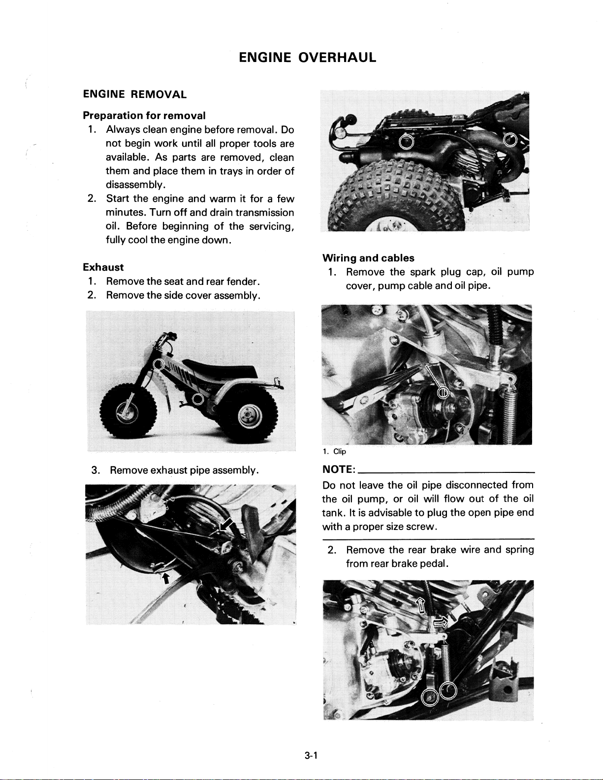
Preparation
1.
REMOVAL
for
removal
Always clean engine before removal.
not begin
available. As parts
them and place them
work
until
all
proper tools are
are
removed, clean
in
trays in order
disassem bly.
2. Start the engine and warm it for a
minutes. Turn
oil. Before beginning
off
and drain transmission
of
the servicing,
fully cool the engine down.
Exhaust
1.
Remove the seat and rear fender.
2. Remove the side cover assembly.
Do
of
few
Wiring
1.
and
cables
Remove the
spark
cover, pump cable and oil pipe.
plug cap, oil pump
3. Remove exhaust pipe assembly.
1. Clip
NOTE:
Do
the oil pump, or oil will
tank. It is advisable
______
not
leave the oil pipe disconnected from
~----------------
flow
out
to
plug the open pipe end
of
the oil
with a proper size screw.
2. Remove the rear brake wire and spring
from rear brake pedal.
3-1
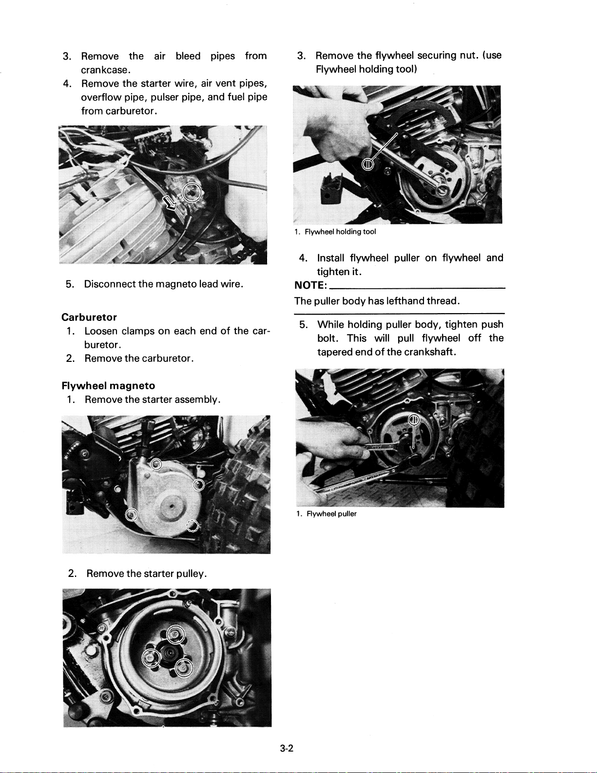
3.
Remove the air bleed pipes from
crankcase.
4. Remove the starter wire, air vent pipes,
overflow pipe, pulser pipe, and fuel pipe
from carburetor.
5.
Disconnect the magneto lead wire.
Carburetor
1.
Loosen clamps on each end
of
the car-
buretor.
2.
Remove the carburetor.
3.
Remove the flywheel securing nut. (use
Flywheel holding tool)
1.
Flywheel holding tool
4. Install flywheel puller on flywheel and
tighten
NOTE:
it.
___________
_
The puller body has lefthand thread.
5.
While holding puller body, tighten push
bolt. This will pull flywheel
of
tapered end
the crankshaft.
off
the
Flywheel
1.
magneto
Remove the starter assembly.
2. Remove the starter pulley.
1.
Aywheel puller
3-2

CHARGING COIL
LIGHTING COIL
FLYWHEEL
MAGNETO
Change
1.
Drive
1.
pedal
Remove the change pedal.
chain
Loosen the drive sprocket lock nut, and
remove the drive chain.
Removal
1.
Remove the engine mounting bolts and
remove engine from right side
of
frame.
ENGINE
Reed
1.
DISASSEMBLY
valve
assembly
Remove reed valve assembly holding
bolts (4), carburetor joint and reed valve
assembly.
Cylinder
1.
head
and
cylinder
Remove the cylinder head holding nuts,
cylinder head and head gasket.
3-3
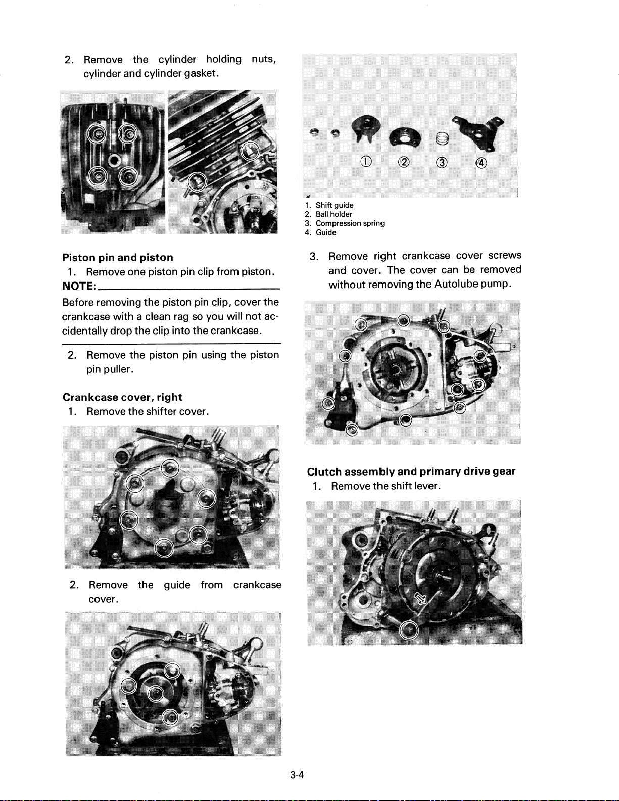
2. Remove the cylinder holding nuts,
cylinder and cylinder gasket.
Piston
1.
NOTE:
pin
and
piston
Remove one piston pin clip from piston.
___________
_
Before removing the piston pin clip, cover the
crankcase with a clean
rag
so
you will
not
ac-
cidentally drop the clip into the crankcase.
1.
Shift guide
2.
Ball
holder
3.
Compression spring
4.
Guide
3.
Remove right crankcase cover screws
and cover. The cover can be removed
without
removing the Autolube pump.
2.
Remove the piston pin using the piston
pin puller.
Crankcase
1.
Remove the shifter cover.
cover,
right
2. Remove the guide from crankcase
cover.
Clutch
1.
assembly
Remove the shift lever.
and
primary
drive
gear
3-4

2. Remove the circlip and pressure plate.
3. Remove the primary drive gear.
rolled-up rag between the tooth
Feed
of
primary drive gear and primary driven
to
gear
lock them and loosen the
primary drive gear lock nut.
a
the
4. Using the Flywheel holding tool, remove
the
nut
and washer. Remove the clutch
boss and driven gear (clutch housing).
1.
Flywheel holding tool
PRESSURE PLATE 2
PRESSURE PLATE 3
3-5
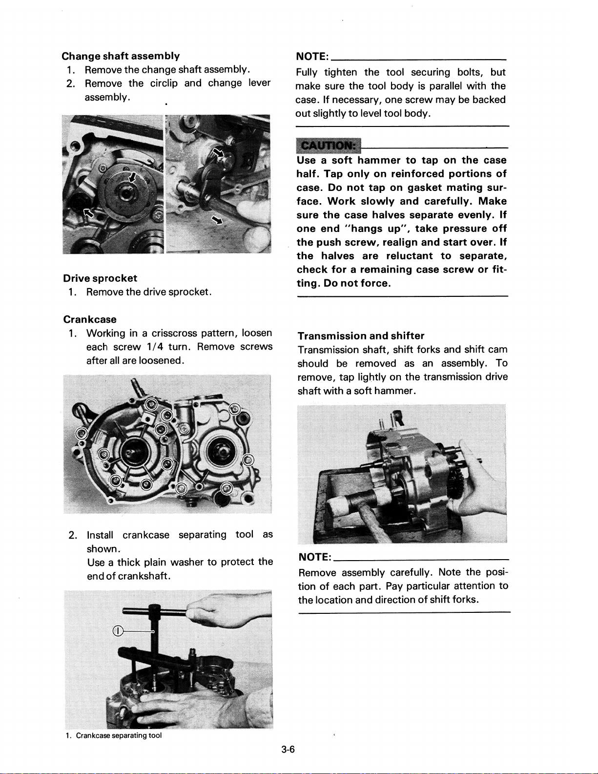
Change
1.
shaft
assembly
Remove the change shaft assembly.
2. Remove the circlip and change lever
assembly.
NOTE:
______________________
__
Fully tighten the tool securing bolts, but
is
make sure the tool body
If
case.
out
necessary, one screw may be backed
slightly
to
level tool body.
parallel with the
Drive
sprocket
1.
Remove the drive sprocket.
Crankcase
1.
Working in a crisscross pattern, loosen
each screw
all
after
1/4
turn. Remove screws
are loosened.
Use a soft
half.
Tap
case.
face.
sure
one
the
the
Do
Work
the
end
push
halves
check
ting.
Do
Transmission
hammer
only
on
reinforced
not
tap
on
slowly
case
"hangs
screw,
are
and
halves
up",
realign
reluctant
for a remaining
not
force.
and
shifter
to
tap
gasket
carefully.
separate
take
and
to
case
on
the
portions
mating
Make
evenly.
pressure
start
over.
separate,
screw
or
case
of
sur-
off
fit-
Transmission shaft, shift forks and shift cam
should be removed
as
an
assembly. To
remove, tap lightly on the transmission drive
shaft
with a soft
hammer.
If
If
2. Install crankcase separating tool
shown.
Use a thick
end
of
1.
Crankcase separating
plain washer
crankshaft.
tool
to
protect the
as
NOTE:
____________
Remove assembly carefully. Note the posi-
of
tion
the location and direction
3-6
each part. Pay particular attention
of
shift forks.
_
to
 Loading...