


YST-SW320
SUBWOOFER SYSTEM
YST-SW320
SERVICE MANUAL
SERVICE MANUAL
IMPORTANT NOTICE
This manual has been provided for the use of authorized YAMAHA
Retailers and their service personnel.
It has been assumed that basic service procedures inherent to the industry,
and more specifically YAMAHA Products, are already known and
understood by the users, and have therefore not been restated.
WARNING: Failure to follow appropriate service and safety
IMPORTANT: The presentation or sale of this manual to any individual
The data provided is believed to be accurate and applicable to the unit(s)
indicated on the cover. The research, engineering, and service departments
of YAMAHA are continually striving to improve YAMAHA products.
Modifications are, therefore, inevitable and specifications are subject to
change without notice or obligation to retrofit. Should any discrepancy
appear to exist, please contact the distributor's Service Division.
WARNING: Static discharges can destroy expensive components.
IMPORTANT: Turn the unit OFF during disassembly and part
procedures when servicing this product may result in
personal injury, destruction of expensive components,
and failure of the product to perform as specified. For
these reasons, we advise all YAMAHA product owners
that any service required should be performed by an
authorized YAMAHA Retailer or the appointed service
representative.
or firm does not constitute authorization, certification
or recognition of any applicable technical
capabilities, or establish a principle-agent relationship
of any form.
Discharge any static electricity your body may have
accumulated by grounding yourself to the ground buss
in the unit (heavy gauge black wires connect to this
buss).
replacement. Recheck all work before you apply power
to the unit.
100720
■ CONTENTS
TO SERVICE PERSONNEL . . . . . . . . . . . . . . . . . . . .1
SPECIFICATIONS . . . . . . . . . . . . . . . . . . . . . . . . . . . .1
REAR PANEL . . . . . . . . . . . . . . . . . . . . . . . . . . . . . . .2
DISASSEMBLY PROCEDURES . . . . . . . . . . . . . . .3–4
ADJUSTMENTS . . . . . . . . . . . . . . . . . . . . . . . . . . . .5–6
PRINTED CIRCUIT BOARD . . . . . . . . . . . . . . . . . 7–12
BLOCK DIAGRAM . . . . . . . . . . . . . . . . . . . . . . . . . . .13
SCHEMATIC DIAGRAM . . . . . . . . . . . . . . . . . . . . . . 14
PARTS LIST . . . . . . . . . . . . . . . . . . . . . . . . . . . . .15–22
YST-SW320

YST-SW320
■ TO SERVICE PERSONNEL
1. Critical Components Information
Components having special characteristics are marked Z
and must be replaced with parts having specifications equal
to those originally installed.
2. Leakage Current Measurement (For 120V Models Only)
When service has been completed, it is imperative to verify
that all exposed conductive surfaces are properly insulated
from supply circuits.
● Meter impedance should be equivalent to 1500 ohm shunted
by 0.15µF.
WALL
OUTLET
● Leakage current must not exceed 0.5mA.
● Be sure to test for leakage with the AC plug in both
polarities.
EQUIPMENT
UNDER TEST
INSULATING
TABLE
AC LEAKAGE
TESTER OR
EQUIVALENT
WARNING: CHEMICAL CONTENT NOTICE!
The solder used in the production of this product contains LEAD. In addition, other electrical/electronic and/or
plastic (where applicable) components may also contain traces of chemicals found by the California Health and
Welfare Agency (and possibly other entities) to cause cancer and/or birth defects or other reproductive harm.
DO NOT PLACE SOLDER, ELECTRICAL/ELECTRONIC OR PLASTIC COMPONENTS IN YOUR MOUTH FOR
ANY REASON WHATSOEVER!
Avoid prolonged, unprotected contact between solder and your skin! When soldering, do not inhale solder fumes
or expose eyes to solder/flux vapor!
If you come in contact with solder or components located inside the enclosure of this product, wash your hands
before handling food.
■ SPECIFICATIONS
Type . . . . . . . . . Advanced Yamaha Active Servo Technology
Driver . . . . . . . . . . . 25 cm (9-13/16") cone woofer (JA25600)
Magnetically shielded type
Amplifier Output . . . . . . . . . . . . . . . . . . . . . . . . . . . . 250W/5Ω
Frequency Response . . . . . . . 20 Hz to 160 Hz (-24 dB/oct.)
Power Supply
U, C models . . . . . . . . . . . . . . . . . . . . . . . . .AC120V, 60 Hz
A model . . . . . . . . . . . . . . . . . . . . . . . . . . . .AC240V, 50 Hz
B, G models . . . . . . . . . . . . . . . . . . . . . . . . .AC230V, 50 Hz
R, T models . . . . . . . . . . . . AC110/120/220/240V, 50/60 Hz
Power Consumption . . . . . . . . . . . . . . . . . . . . . . . . . . . . .60W
Dimensions (W x H x D) . . . . . . . . . . . . 340 x 432 x 370 mm
(13-3/8" x 17" x 14-9/16")
Weight . . . . . . . . . . . . . . . . . . . . . . . . . . . 17 kg (37 lbs. 7 oz)
Finish
All model . . . . . . . . . . . . . . . . . . . . . . . . . . . . . . Black color
R, T, G models . . . . . . . . . . . . . . . . . . . . . . . . Cherry color
Accessories . . . . . . . . . . . . . . . . . . . . . . . . . . Nonskid pad x 4
* Specifications subject to change without notice.
U . . . . . . . . . . USA model
C . . . . . .Canadian model
A . . . . . Australian model
B . . . . . . . . British model
G . . . . . European model
R . . . . . . . General model
T . . . . . . . . . China model
1
YST-SW320
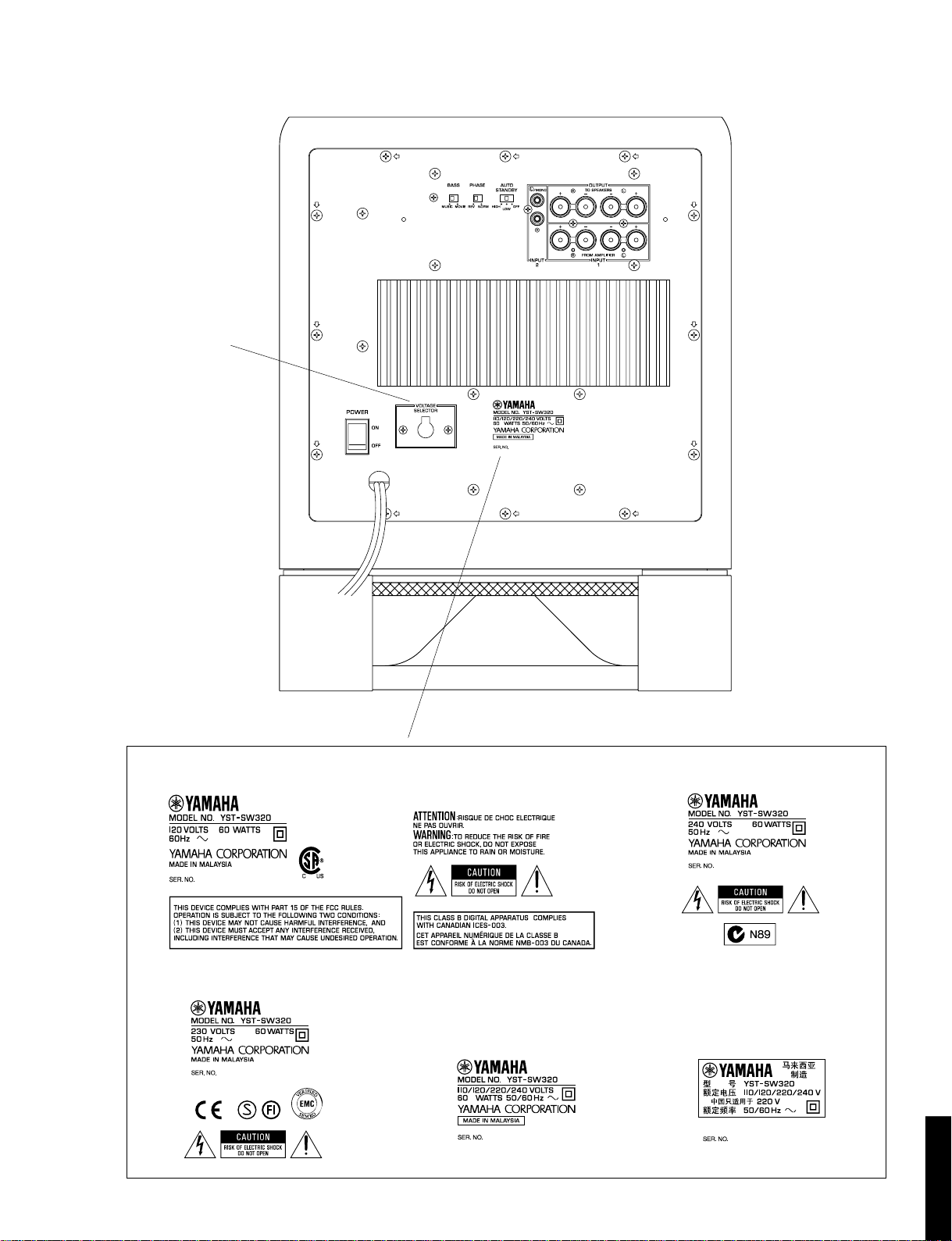
■ REAR PANEL
R, T models only
YST-SW320
▼ U, C models ▼ A model
▼ B, G models
▼ R model ▼ T model
YST-SW320
2

YST-SW320
■ DISASSEMBLY PROCEDURES
(Remove parts in the order as numbered.)
1. Removal of Front Panel Ass'y
Remove 4 screws ( q ) and then remove the Front
Panel Ass'y in Fig. 1.
* Use an Allen wrench (3mm) to unscrew the Front
Panel Ass'y.
Front Panel Ass'y
q
q
Main (5) P.C.B.
Fig. 1
3. Removal of Rear Panel Ass'y
Remove 12 screws ( r ) in Fig. 3.
* Arrow marks ( ) are printed to identify the screws to be
removed.
Rear Panel Ass'y
r
r
r
r
Fig. 3
2. Removal of Loud Speaker
a. Remove 8 screws ( w ) and then remove the Base
Ass'y in Fig. 2.
b. Remove 4 screws ( e ) and then remove the Loud
Speaker in Fig. 2.
w
w
w
e
Loud Speaker
w
Base Ass'y
e
* When assembling the Rear Panel, check to ensure that
the gasket is not damaged so as to prevent air leakage
from occurring.
● Installation of emblem
1. Put the emblem into the cabinet at the specified position.
2. Place a piece of cloth/wood on top of the emblem.
3. Using a mallet, hammer the emblem in place through
the cloth/wood.
* Use special care not to cause damage to the emblem or
cabinet while hammering the emblem.
3
YST-SW320
Fig. 2

● Installation of power switch
Rapid cures bond (such as 5 minute epoxy) is required to fix the power switch.
As shown in Fig. A, apply r apid cures bond (such as 5 minute epo xy) to the pow er s witch (the area which
contacts the rear panel), insert it in the rear panel and make sure it is fixed.
(Inserting the power switch in the rear panel only would not be sufficient for its secure installation.)
●
Precaution for installation of power cord
After connecting the power cord, be sure to apply the rapid cures bond (such as 5 minute epo xy) to the
cord stopper as shown in Fig. A,
YST-SW320
Bond application diagram (Fig. A)
Apply rapid cures bond
Apply rapid cures bond
Glue List
Place Name
Cord stopper
Power switch 5 minute epoxy or Diabond 1620B
5 minute epoxy or
2051(Revertex Finewaters SDN.BHD.) or
VYLOK 917DH (National Starch &
Chemical (M) SDM.BHD.)
● Dimensions
340 (13-3/8")
(5/16")
340 (13-3/8")
432 (17")
8
370 (14-9/16")
340 (13-3/8")
22
(7/8")
YST-SW320
Units : mm (inch)
4

YST-SW320
■ ADJUSTMENTS
●
Confirmation of Power Amp operation
For the power amplifier which has been repaired, it
is absolutely necessary to confirm that a correct
waveform is obtained at points indicated by A and B
in the schematic diagram according to the following
procedure.
Devices required
Signal generator
8Ω or 6Ω load resistor
Oscilloscope (dual trace type)
Connection
1) Connect the output signal from the signal generator
to the input terminal of YST-SW320.
2) Disconnect the connector terminal connected to the
speaker unit and reconnect it to the load resistor.
3) Connect the HOT side of the oscilloscope CH1 probe
to the point A or B indicated in the figure and the
GND side to the GND of the main unit.
4) Connect the oscilloscope CH2 input to the red side
of the connector cable, which is connected with the
load resistor.
At this time, the GND terminal of CH2 must be left
unconnected.
Setting
1) Set the signal generator to the sine wave, 100Hz and
minimum output level settings.
2) Set the volume of YST-SW320 to the minimum
position.
3) Turn on the power to YST-SW320.
4) Adjust the output level of the signal generator and the
volume of YST-SW320 so that the output level
observed at oscilloscope CH2 is 28Vp-p.
● Idling Adjustment
To stabilize operation of the amplifier, turn ON the
power with no input signal and wait for 1 or 2 minutes
in non loaded condition before the adjustment.
Adjust VR1 so that the voltage between terminals
TP11 and TP12 is DC 50mV to 250mV.
● Confirmation of AUTO STANDBY
Measuring Condition
R60 = 1MΩ
➔1MΩ//10kΩ
F = 100Hz
Input Level = 4mV
Load = Open
Rating
After 2 to 8 sec.
STANDBY
(LED become red)
Don't STANDBY
Remarks
VOLUME: MAX
HIGH CUT: MAX
AUTO STANDBY: LOW
VOLUME: MAX
HIGH CUT: MAX
AUTO STANDBY: HIGH
Waveform observation
With the settings made as described above, observe
the waveform obtained at CH1 for judgment.
0V
5
YST-SW320
Normal Normal
Point A (Cathode of D29)
V : 20V/div H : 2 msec/div
DC range 1 : 1 probe
Abnormal
+B or GND level
Becomes constant
Point B (Anode of D30)
V : 20V/div H : 2 msec/div
DC range 1 : 1 probe
0V
Abnormal
-B or GND level
Becomes constant
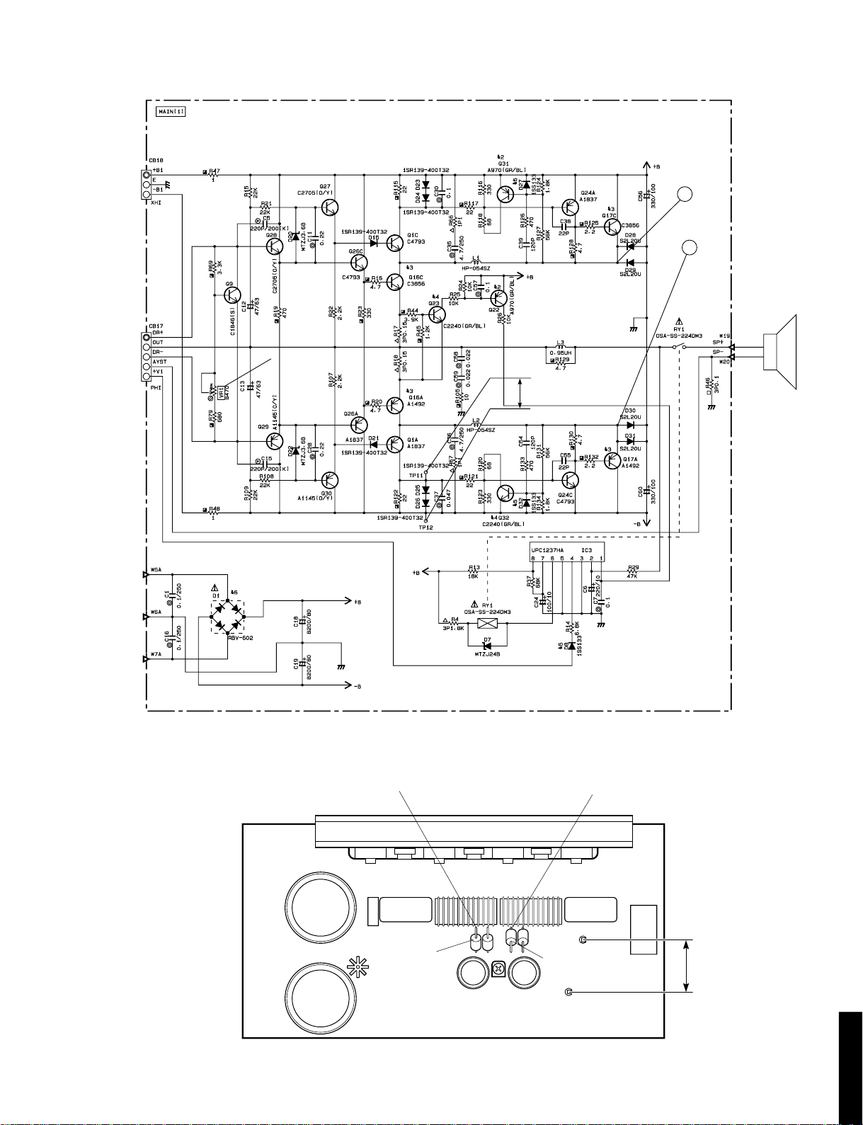
● Schematic Diagram
YST-SW320
A
B
IDLING CURRENT ADJ.
RE
WH
DC 50mV to 250mV
● Test Points
Point A
D29
Main (1) P.C.B
VR1
D30
Point B
TP11 (+)
TP12 (-)
DC 50mV to 250mV
YST-SW320
6