

Page 1
@YAM
AHA
Service
Page 2
YS R5OT
SERVICE MANUAL
01987 by
All rights reserved. Any reprinting or
unauthorized use without the written
permission of Yamaha Motor Corporation,
Yamaha Motor Corporation, U.S.A.
1st Edition, March 1987
U.S.A. is expressly prohibited.
Printed in U.S.A.
PINO. LIT-Il616-O6-05
Page 3
NOTICE
This manual was written by the Yamaha Motor Company primarily for use by Yamaha dealers and
It
their qualified mechanics.
it
is assumed that persons using this book to perform maintenance and repairs on Yamaha motor-
so
cycles have a basic understanding of the mechanical concepts and procedures inherent in motorcycle
repair technology. Without such knowledge, attempted repairs or service to this model may render
it
unfit to use andlor unsafe.
Yamaha Motor Company, Ltd. is continually striving to improve all models manufactured by Yamaha.
Modifications and significant changes in specifications or procedures will be forwarded to all Authorized
Yamaha dealers and will, where applicable, appear in future editions of this manual.
is not possible to put an entire mechanic's education into one manual,
HOW TO USE THIS MANUAL
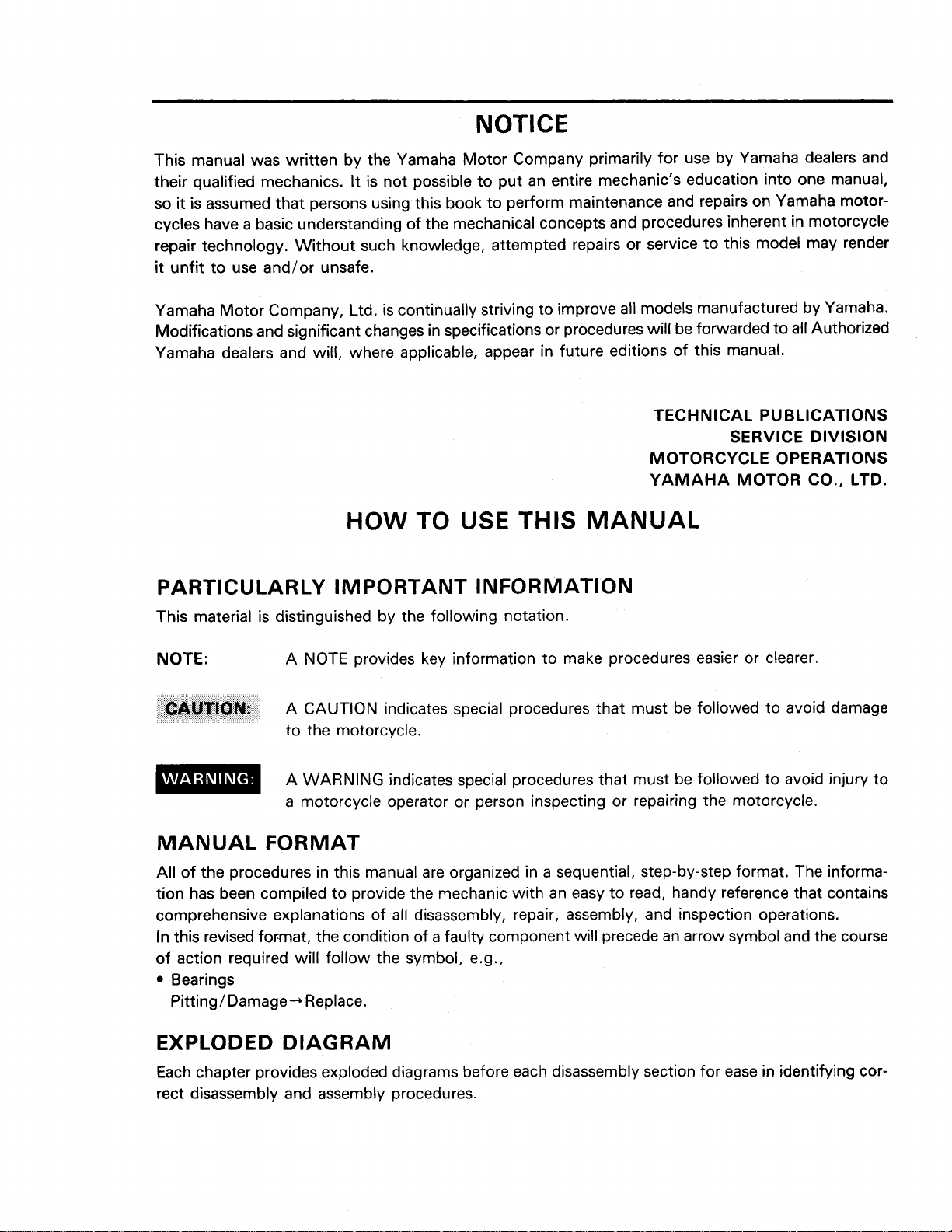
PARTICULARLY IMPORTANT INFORMATION
This material is distinguished by the following notation.
NOTE:
MANUAL FORMAT
A NOTE provides key information to make procedures easier or clearer.
A CAUTION indicates special procedures that must be followed to avoid damage
to the motorcycle.
A WARNING indicates special procedures that must be followed to avoid injury to
a motorcycle operator or person inspecting or repairing the motorcycle.
TECHNICAL
MOTORCYCLE OPERATIONS
YAMAHA MOTOR CO., LTD.
PU
BLlCATlONS
SERVICE DIVISION
All of the procedures in this manual are organized in a sequential, step-by-step format. The information has been compiled to provide the mechanic with an easy to read, handy reference that contains
comprehensive explanations of all disassembly, repair, assembly, and inspection operations.
In this revised format, the condition of a faulty component will precede an arrow symbol and the course
of action required will follow the symbol, e.g.,
Bearings
Pitting1 Damage-, Replace.
EXPLODED DIAGRAM
Each chapter provides exploded diagrams before each disassembly section for ease in identifying cor-
rect disassembly and assembly procedures.
Page 4
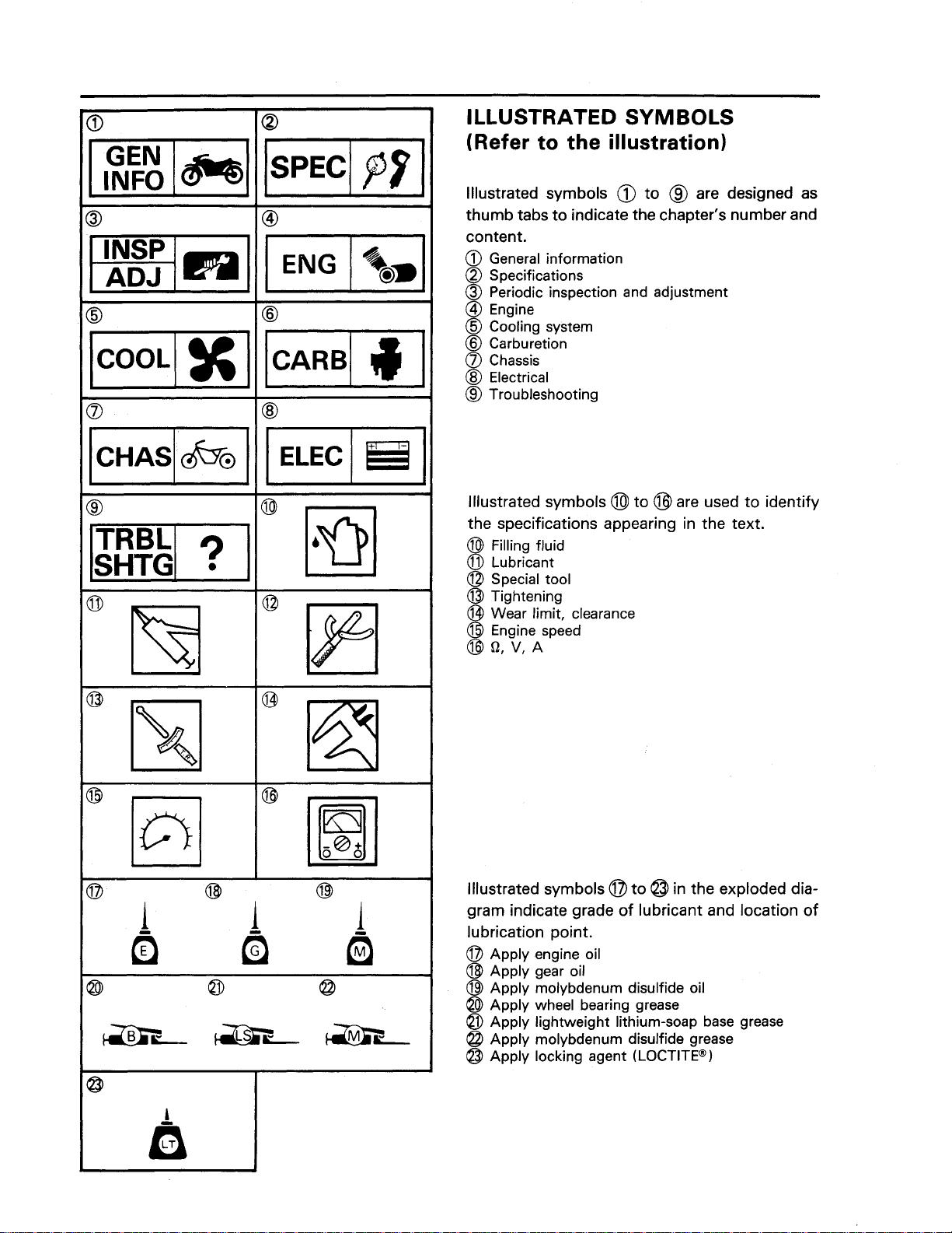
ILLUSTRATED SYMBOLS
(Refer to the illustration)
I
ENG
1
Illustrated symbols
thumb tabs to indicate the chapter's number and
content.
a
General information
@
Specifications
@
Periodic inspection and adjustment
@
Engine
@
Cooling system
@
Carburetion
a
Chassis
@
Electrical
@
Troubleshooting
Illustrated symbols @ to @ are used to identify
the specifications appearing in the text.
@
Filling fluid
Lubricant
@
Special tool
@
Tightening
@
Wear limit, clearance
@
Engine speed
@
9,
v,
A
@
to @ are designed as
Illustrated symbols
gram indicate grade of lubricant and location of
lubrication point.
0
Apply engine oil
@
Apply gear oil
8
Apply molybdenum disulfide oil
@
Apply wheel bearing grease
Apply lightweight lithium-soap base grease
@
Apply molybdenum disulfide grease
@
Apply locking agent (LOCTITE@)
0
to @ in the exploded dia-
Page 5
INDEX
GENERAL INFORMATION
SPECIFICATIONS
m
GEN
INFO
P
f
PERIODIC INSPECTION
AND ADJUSTMENT
ENGINE OVERHAUL
CHASSIS
em
INSP
ADJ
@
+o,
&O
ELECTRICAL
TROUBLESHOOTING
El
ELEC
0
Page 6
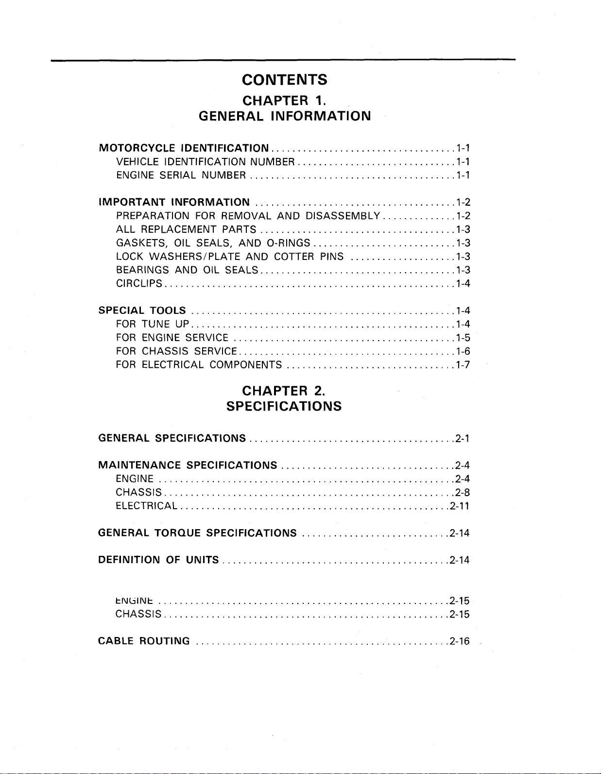
CONTENTS
CHAPTER
1
.
GENERAL INFORMATION
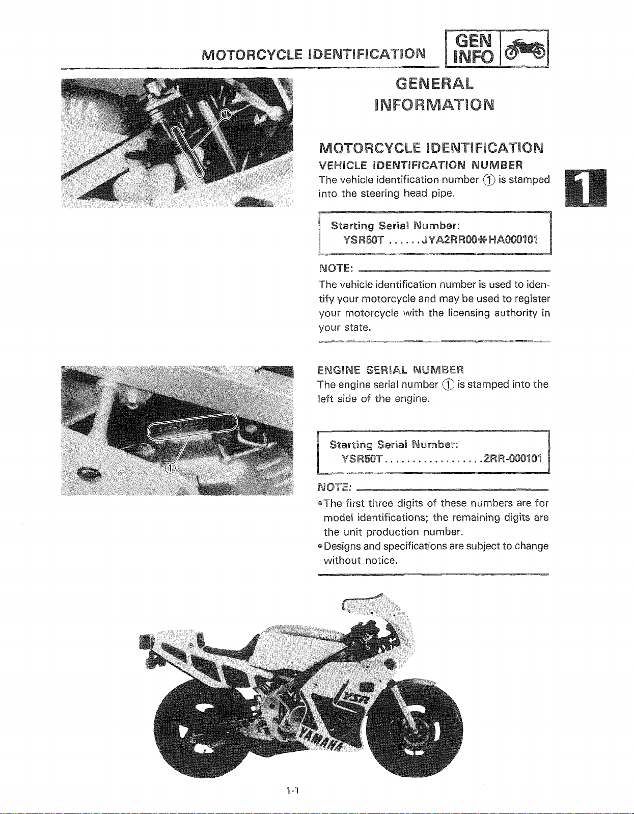
MOTORCYCLE IDENTIFICATION
VEHICLE IDENTIFICATION NUMBER
ENGINE SERIAL NUMBER
IMPORTANT INFORMATION
PREPARATION FOR REMOVAL AND DISASSEMBLY
ALL REPLACEMENT PARTS
GASKETS, OIL SEALS. AND O.RINGS
LOCK WASHERSIPLATE AND COTTER PINS
BEARINGS AND OIL SEALS
ClRCLlPS
SPECIAL TOOLS
FOR TUNE
FOR ENGINE SERVICE
FOR CHASSIS SERVICE
FOR ELECTRICAL COMPONENTS
.......................................................
..................................................
UP
..................................................
..........................................
.........................................
...................................
..............................
.......................................
......................................
.....................................
...........................
.....................................
................................
..............
....................
1.1
1.1
1.1
1.2
1.2
1.3
1.3
1.3
1.3
1-4
1-4
1-4
1.5
1.6
1.7
CHAPTER
SPECIFICATIONS
GENERAL SPECIFICATIONS
MAINTENANCE SPECIFICATIONS
ENGINE
CHASSIS
ELECTRICAL
GENERAL TORQUE SPECIFICATIONS
DEFINITION OF UNITS
tNtiINt
CHASSIS
CABLE ROUTING
........................................................
.......................................................
...................................................
.......................................................
......................................................
................................................
.......................................
.................................
...........................................
2 .
2.11
............................
2.14
2.14
2-15
2-15
2.16
2.1
2.4
2-4
2-8
Page 7
--
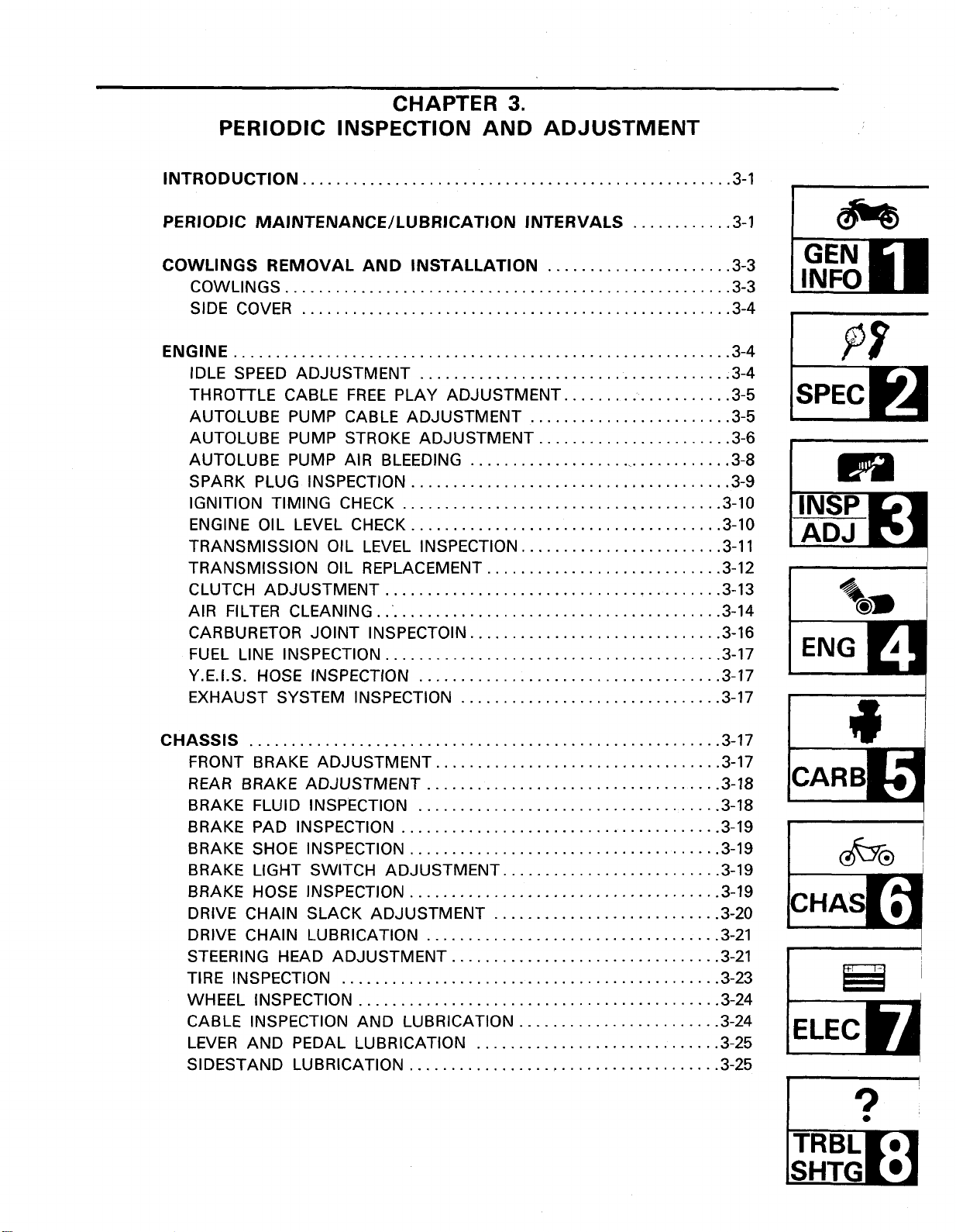
CHAPTER
3
.
-
PERIODIC INSPECTION AND ADJUSTMENT
INTRODUCTION
PERIODIC MAINTENANCE/LUBRlCATlON INTERVALS
COWLINGS REMOVAL AND INSTALLATION
COWLINGS
SIDE COVER
ENGINE
...........................................................
IDLE SPEED ADJUSTMENT
THROTTLE CABLE FREE PLAY ADJUSTMENT
AUTOLUBE PUMP CABLE ADJUSTMENT
AUTOLUBE PUMP STROKE ADJUSTMENT
AUTOLUBE PUMP AIR BLEEDING
SPARK PLUG INSPECTION
IGNITION TIMING CHECK
ENGINE OIL LEVEL CHECK
TRANSMISSION OIL LEVEL INSPECTION
TRANSMISSION OIL REPLACEMENT
CLUTCH ADJUSTMENT
AIR FILTER CLEANING
CARBURETOR JOINT INSPECTOIN
FUEL LINE INSPECTION
Y.E.I.S. HOSE INSPECTION
EXHAUST SYSTEM INSPECTION
...................................................
......................
.....................................................
...................................................
.....................................
....................
........................
.......................
................................
......................................
......................................
.....................................
........................
............................
........................................
..........................................
..............................
........................................
....................................
...............................
............
3.10
3.10
3.11
3.12
3.13
3.14
3.16
3.17
3.17
3.17
3-1
3.1
3.3
3-3
3.4
3.4
3.4
3.5
3.5
3.6
3.8
3.9
INFO
CHASSIS
FRONT BRAKE ADJUSTMENT
REAR BRAKE ADJUSTMENT
BRAKE FLUID INSPECTION
BRAKE PAD INSPECTION
BRAKE SHOE INSPECTION
BRAKE LIGHT SWITCH ADJUSTMENT
BRAKE HOSE INSPECTION
DRIVE CHAIN SLACK ADJUSTMENT
DRIVE CHAIN LUBRICATION
STEERING HEAD ADJUSTMENT
TIRE INSPECTION
WHEEL INSPECTION
CABLE INSPECTION AND LUBRICATION
LEVER AND PEDAL LUBRICATION
SIDESTAND LUBRICATION
........................................................
..................................
...................................
....................................
......................................
.....................................
.....................................
...................................
.............................................
...........................................
.....................................
..........................
...........................
................................
........................
.............................
3-17
3.17
3.18
3.18
3.19
3.19
3.19
3.19
3.20
3.21
3.21
3.23
3.24
3.24
3.25
3.25
Page 8
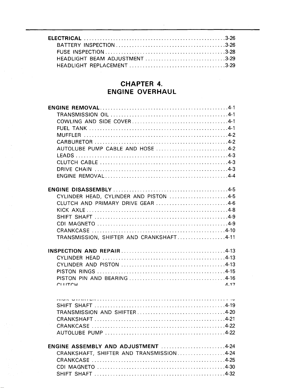
ELECTRICAL
BATTERY INSPECTION
FUSE INSPECTION
HEADLIGHT BEAM ADJUSTMENT
HEADLIGHT REPLACEMENT
.....................................................
.........................................
.............................................
3-26
3.26
3.28
..............................
....................................
3.29
3.29
CHAPTER
ENGINE
ENGINE REMOVAL
TRANSMISSION OIL
COWLING AND SIDE COVER
FUEL TANK
MUFFLER
CARBURETOR
AUTOLUBE PUMP CABLE AND HOSE
LEADS
CLUTCH CABLE
DRIVE CHAIN
ENGINE REMOVAL
ENGINE DISASSEMBLY
CYLINDER HEAD. CYLINDER AND PISTON
CLUTCH AND PRIMARY DRIVE GEAR
KICK AXLE
SHIFT SHAFT
CDI MAGNETO
CRANKCASE
TRANSMISSION. SHIFTER AND CRANKSHAFT
......................................................
.........................................................
................................................
............................................
....................................................
..................................................
................................................
..................................................
..............................................
...........................................
.....................................................
..................................................
.................................................
..................................................
OVERHAUL
....................................
4
...........................
...........................
.
......................
..................
4-1
4-1
4-1
4-1
4-2
4-2
4.2
4-3
4.3
4-3
4.4
4.5
4.5
4.6
4-8
4-9
4-9
4-10
4.11
INSPECTION AND REPAIR
CYLINDER HEAD 4-13
CYLINDER AND PISTON 4.13
PISTON RINGS 4-15
PISTON PIN AND BEARING
rl
I
IT~U
...
w. . w..
SHIFT SHAFT
TRANSMISSION AND SHIFTER
CRANKSHAFT
CRANKCASE
AUTOLUBE PUMP
ENGINE ASSEMBLY AND ADJUSTMENT
CRANKSHAFT. SHIFTER AND TRANSMISSION
CRANKCASE
CDI MAGNETO
SHIFT SHAFT
....
..............................................
................................................
L.
...................................................
.................................................
.................................................
..................................................
.............................................
..................................................
................................................
.................................................
.......................................
.......................................
....................................
.................................
........................
..................
4.13
4.16
4-17
"
4-19
4-20
4-21
4-22
4-22
4.24
4.24
4-25
4-30
4-32
Page 9
KICK AXLE
CLUTCH AND PRIMARY DRIVE GEAR
CYLINDER HEAD. CYLINDER AND PISTON
REMOUNTING ENGINE
....................................................
..........................
.........................................
4-32
4.34
..................... 4.37
4.40
CHAPTER
5
.
CARBURETION
CARBURETOR
REMOVAL
DISASSEMBLY
INSPECTION
INSTALLATION
ADJUSTMENT
REED VALVE
REMOVAL
INSPECTION
INSTALLATION
...................................................
......................................................
.................................................
....................................................
..................................................... ASSEMBLY 5-5
.................................................
..................................................
.....................................................
......................................................
....................................................
.................................................
CHAPTER
6
.
CHASSIS
FRONT WHEEL
REMOVAL 6-2
INSPECTION 6-2
INSTALLATION
....................................................
......................................................
....................................................
.................................................
-5-1
5-2
5-2
5.4
5.6
5-7
5-8
5-8
5-8
5.9
6-1
6-4
REAR WHEEL
REMOVAL 6.6
INSPECTION 6.6
INSTALLATION 6.8
FRONT BRAKE
BRAKE PAD REPLACEMENT 6.11
CALIPER DISASSEMBLY 6.13
MASTER CYLINDER DISASSEMBLY 6.14
INSPECTION AND REPAIR 6.15
ASSEMBLY
AIR BLEEDING 6-19
FRONT FORK
REMOVAL 6.21
DISASSEMBLY 6.21
INSPECTION 6.23
ASSEMBLY 6.23
INSTALLATION 6-26
.....................................................
......................................................
....................................................
.................................................
...................................................
...................................
.......................................
............................
......................................
....................................................
................................................
....................................................
.....................................................
................................................
...................................................
....................................................
................................................
6-5
6.10
6-16
6.20
Page 10
STEERING HEAD AND HANDLEBAR
REMOVAL
INSPECTION
l
NSTALLATION
.....................................................
...................................................
................................................
............................. 6.27
6-28
6-29
6.30
REAR SHOCK ABSORBER AND SWINGARM
REMOVAL
DISASSEMBLY
INSPECTION
ASSEMBLY
INSTALLATION
DRIVE CHAIN AND SPROCKETS
REMOVAL
INSPECTION
INSTALLATION
.....................................................
................................................
...................................................
....................................................
...............................................
................................. 6.38
..................................................... 6-38
...................................................
................................................
CHAPTER
7
.
ELECTRICAL
YSR50T CIRCUIT DIAGRAM
COLOR CODE
ELECTRICAL COMPONENTS
IGNITION AND STARTING SYSTEM
IGNITION CONTROL CIRCUIT OPERATION
TROUBLESHOOTING
.................................................. 7-2
.......................................
......................................
...............................
............................................
....................
6.33
6-34
6-35
6-35
6-36
-6-36
6.38
6.39
7-1
7.3
7-4
....................... 7.6
7.7
CHARGING SYSTEM
TROUBLESHOOTING
LIGHTING SYSTEM
TROUBLESHOOTING (1) 7.24
TROUBLESHOOTING (2) 7.27
SIGNAL SYSTEM
TROUBLESHOOTING
DISPLAY SYSTEM
TROUBLESHOOTING
TROUBLESHOOTING (2)
DISPLAY SYSTEM TEST AND CHECK
.............................................
...........................................
...............................................
........................................
........................................
.................................................
........................................... 7.32
................................................
(1
)
........................................ 7.44
........................................
...........................
CHAPTER
8
.
TROUBLESHOOTING
STARTING FAILUREIHARD STARTING
FUEL SYSTEM
ELECTRICAL SYSTEM
COMPRESSION SYSTEM
.................................................
...........................................
........................................
............................
7.16
7.18
7.22
7.30
7.42
7.48
7.50
8.1
8.1
8.2
8.3
Page 11
POOR IDLE SPEED PERFORMANCE
POOR IDLE SPEED PERFORMANCE
...............................
..............................
8.3
8.3
POOR MEDIUM AND HIGH SPEED PERFORMANCE
FUEL SYSTEM
ELECTRICAL SYSTEM
COMPRESSION SYSTEM
FAULTY GEAR SHIFTING
HARD SHIFTING
CHANGE PEDAL DOES NOT MOVE
JUMP-OUT GEAR
CLUTCH SLIPPINGIDRAGGING
CLUTCH SLIPPING
CLUTCH DRAGGING
IMPROPER KICKING
SLIPPING
HARD KICKING
KICK CRANK NOT RETURNING
FAULTY BRAKE
POOR BRAKING EFFECT
.................................................
...........................................
........................................
.........................................
................................................
..............................
...............................................
...................................
..............................................
............................................
..............................................
......................................................
.................................................
.................................
...................................................
........................................
..............
8.4
8.4
8.4
8.5
8.6
8-6
pqm
INFO
8-6
8-6
8.7
8.7
8-7
8-8
8-8
8-8
8.8
8-9
8.9
FRONT FORK OIL LEAKAGE AND FRONT FORK MALFUNCTION
OIL LEAKAGE
MALFUNCTION
INSTABLE HANDLING
INSTABLE HANDLING
FAULTY SIGNAL AND LIGHTING SYSTEM
HEADLIGHT DARK
BULB BURNT OUT
FLASHER DOES NOT LIGHT
FLASHER KEEPS ON
FLASHER WINKS SLOWER
FLASHER WINKS QUICKER
HORN IS INOPERATIVE
OVERHEATING
OVERHEATING
YSR5OT WIRING DIAGRAM
..................................................
.................................................
........................................... 8.10
.........................................
.......................
.............................................
............................................
...................................
.......................................... 8.11
....................................
....................................
........................................
...................................................
................................................
.... 8.9
8-9
8-9
8.10
8.11
8-11
8.11
8.11
8.12
8.12
8.12
8.13
8-13
Page 12

Page 13
your state.
IAL
N
The engine serial num
sf
the
left side
en
::.
cThe first three di ts sf these numbers are for
ns;
%he
model identificat
duction number.
specifications are su
without notice.
remainin
-
Page 14
IMPORTANT INFORMATION
IMPORTANT INFORMATION
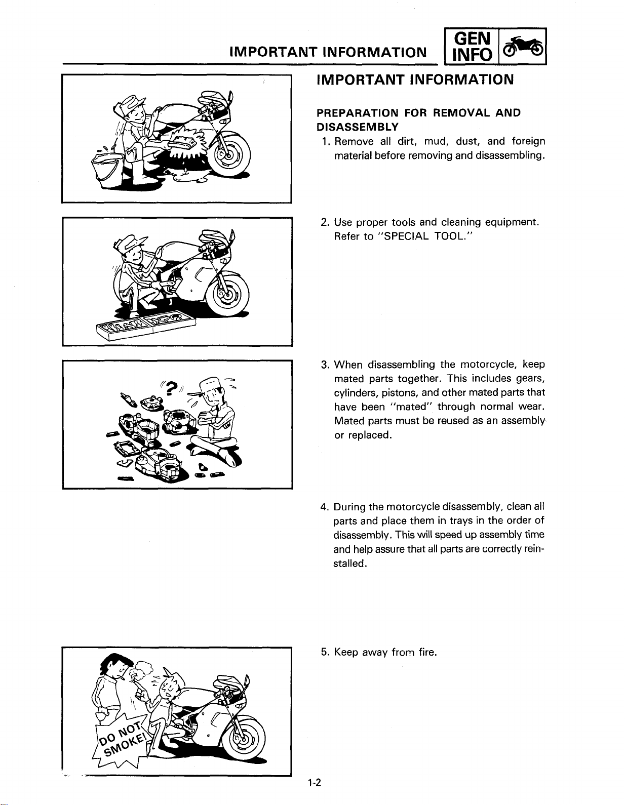
PREPARATION FOR REMOVAL AND
DISASSEMBLY
1.
Remove all dirt, mud, dust, and foreign
material before removing and disassembling.
2.
Use proper tools and cleaning equipment.
Refer to "SPECIAL TOOL."
I
1-1
3.
When disassembling the motorcycle, keep
mated parts together. This includes gears,
cylinders, pistons, and other mated parts that
have been "mated" through normal wear.
Mated parts must be reused as an assembly
or replaced.
4.
During the motorcycle disassembly, clean all
parts and place them in trays in the order of
disassembly. This will speed up assembly time
and help assure that all parts are correctly rein-
stalled.
5.
Keep away from fire.
Page 15
IMPORTANT INFORMATION
ALL REPLACEMENT PARTS
1.
We recommend to use Yamaha genuine parts
for all replacements. Use oil and/or grease
recommended by Yamaha for assembly and
adjustment.
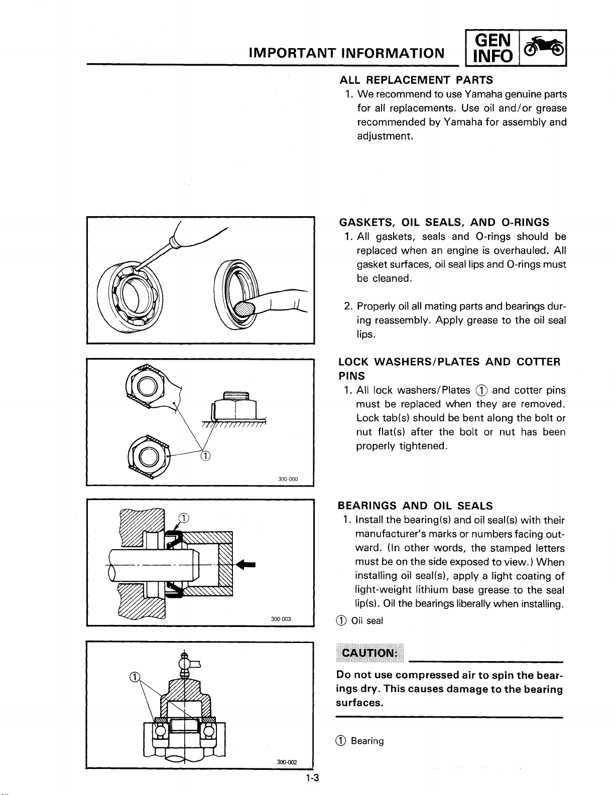
GASKETS, OIL SEALS, AND O-RINGS
1.
All gaskets, seals and O-rings should be
replaced when an engine is overhauled. All
gasket surfaces, oil seal lips and O-rings must
be cleaned.
2.
Properly oil all mating parts and bearings during reassembly. Apply grease to the oil seal
lips.
PI
LOCK WASHERSIPLATES AND COlTER
PINS
1.
All lock washers1Plates @ and cotter pins
must be replaced when they are removed.
Lock tab(s) should be bent along the bolt or
nut flat(s) after the bolt or nut has been
properly tightened.
BEARINGS AND OIL SEALS
1.
Install the bearing(s1 and oil seal(s) with their
manufacturer's marks or numbers facing outward. (In other words, the stamped letters
must be on the side exposed to view. When
installing oil
light-weight lithium base grease to the seal
lip(s). Oil the bearings liberally when installing.
@
Oil
seal
seal(s), apply a light coating of
Do not use compressed air to spin the bearings dry. This causes damage to the bearing
surfaces.
@
Bearing
Page 16
SPEClAL TOOLS
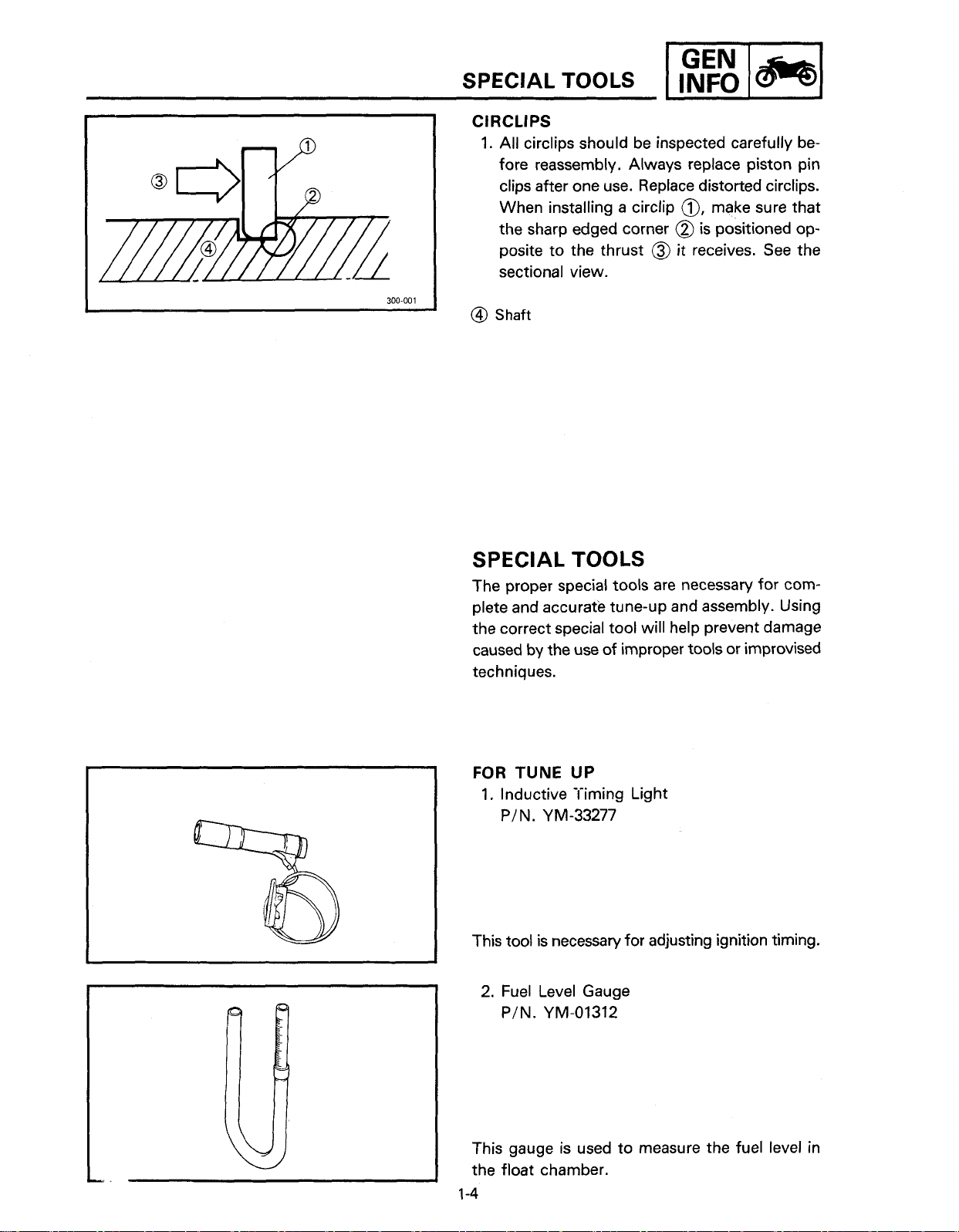
ClRCLlPS
1.
All circlips should be inspected carefully before reassembly. Always replace piston pin
clips after one use. Replace distorted circlips.
When installing a circlip
the sharp edged corner
posite to the thrust
sectional view.
@I
Shaft
-1
@,
make sure that
@
is
positioned op-
@
it receives. See the
SPECIAL TOOLS
The proper special tools are necessary for complete and accurate tune-up and assembly. Using
the correct special tool will help prevent damage
caused by the use of improper tools or improvised
techniques.
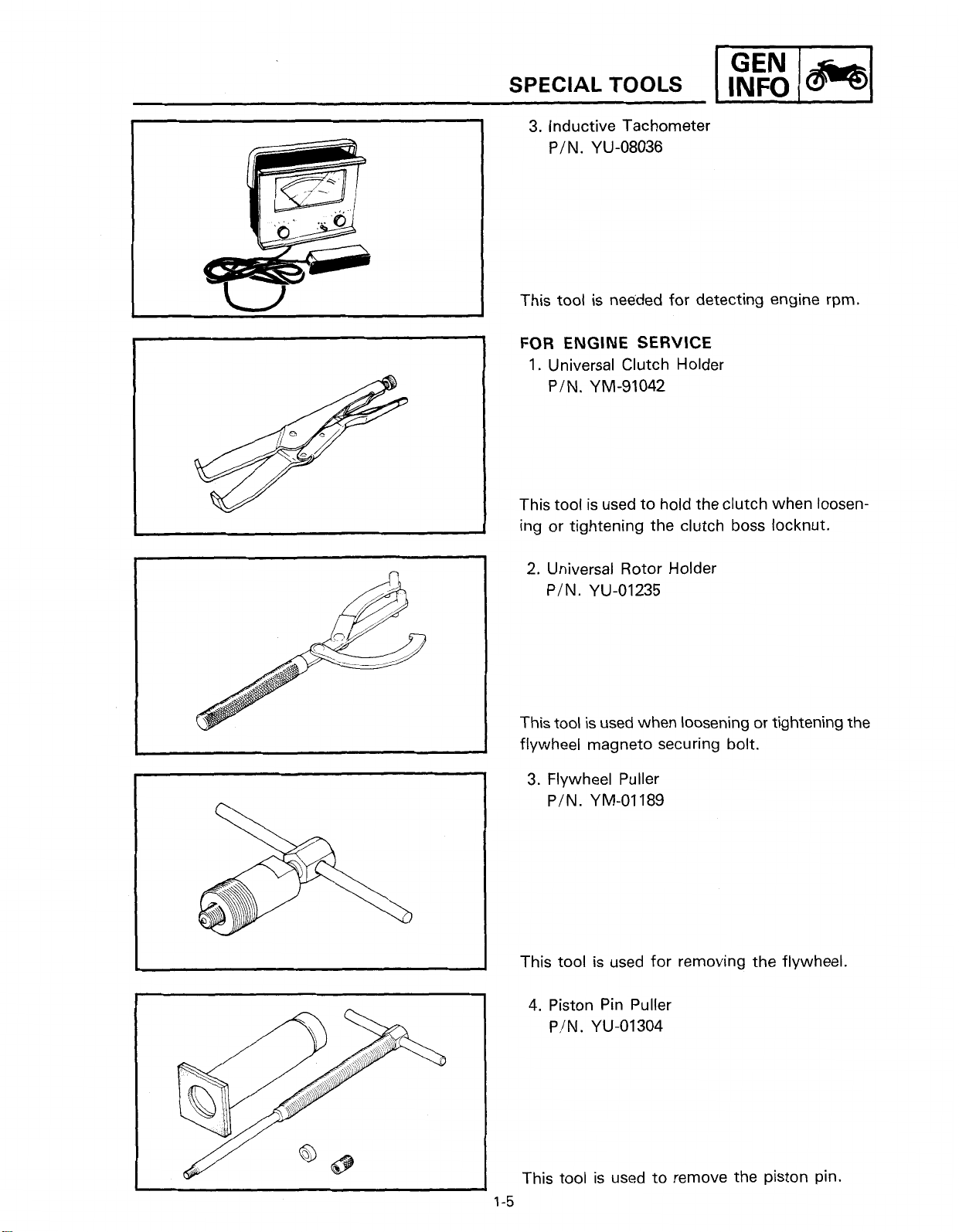
FOR
TUNE
1.
Inductive Timing Light
PIN.
This tool is necessary for adjusting ignition timing.
2.
Fuel Level Gauge
PIN.
UP
YM-33277
YM-01312
This gauge is used to measure the fuel level in
the float chamber.
1-4
Page 17
3.
Inductive Tachometer
YU-08036
PIN.
This tool is needed for detecting engine rpm.
FOR ENGINE SERVICE
1.
Universal Clutch Holder
YM-91042
PIN.
This tool is used to hold the clutch when loosening or tightening the clutch boss locknut.
2.
Universal Rotor Holder
YU-01235
PIN.
This tool is used when loosening or tightening the
flywheel magneto securing bolt.
3.
Flywheel Puller
YM-01189
PIN.
This tool is used for removing the flywheel.
4.
Piston Pin Puller
YU-01304
PIN.
This tool is used to remove the piston pin.
Page 18
SPECIAL
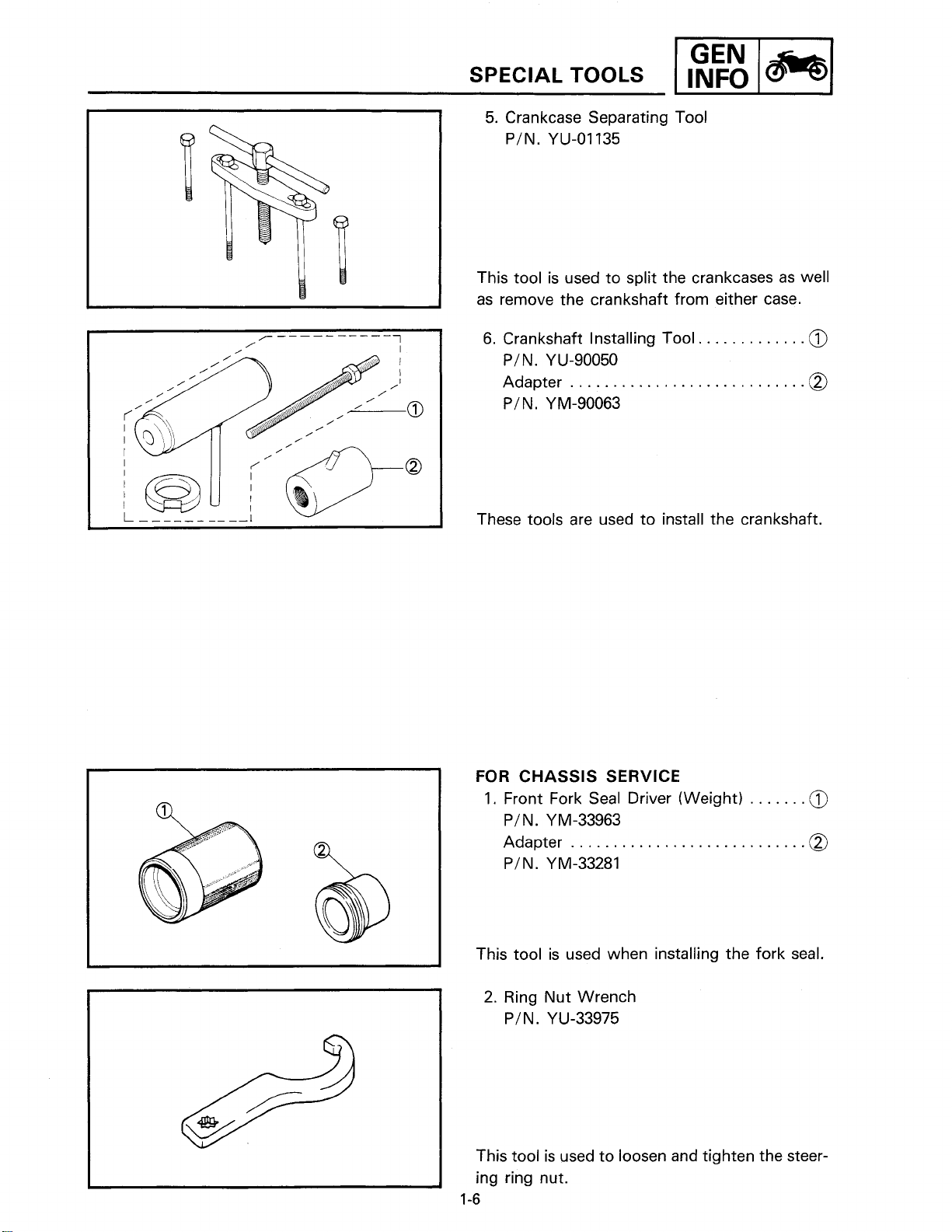
5.
Crankcase Separating Tool
PIN.
This tool is used to split the crankcases as well
as remove the crankshaft from either case.
TOOLS
YU-01135
wl
6.
Crankshaft Installing Tool
PIN.
YU-90050
Adapter
PIN.
These tools are used to install the crankshaft.
FOR
CHASSIS SERVICE
1.
Front Fork Seal Driver (Weight)
PIN.
Adapter
PIN.
............................
YM-90063
YM-33963
..........................
YM-33281
.............
0
0
.....
This tool is used when installing the fork seal.
2.
Ring Nut Wrench
YU-33975
PIN.
This tool is used to loosen and tighten the steering ring nut.
1-6
Page 19
GEN
SPECIAL TOOLS
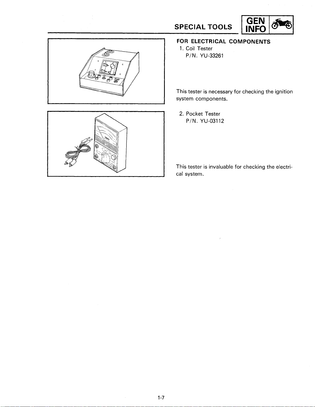
FOR
ELECTRICAL COMPONENTS
1.
Coil Tester
YU-33261
PIN.
This tester is necessary for checking the ignition
system components.
2.
Pocket Tester
YU-03112
PIN.
This tester is invaluable for checking the electrical system.
wl
Page 20
Page 21
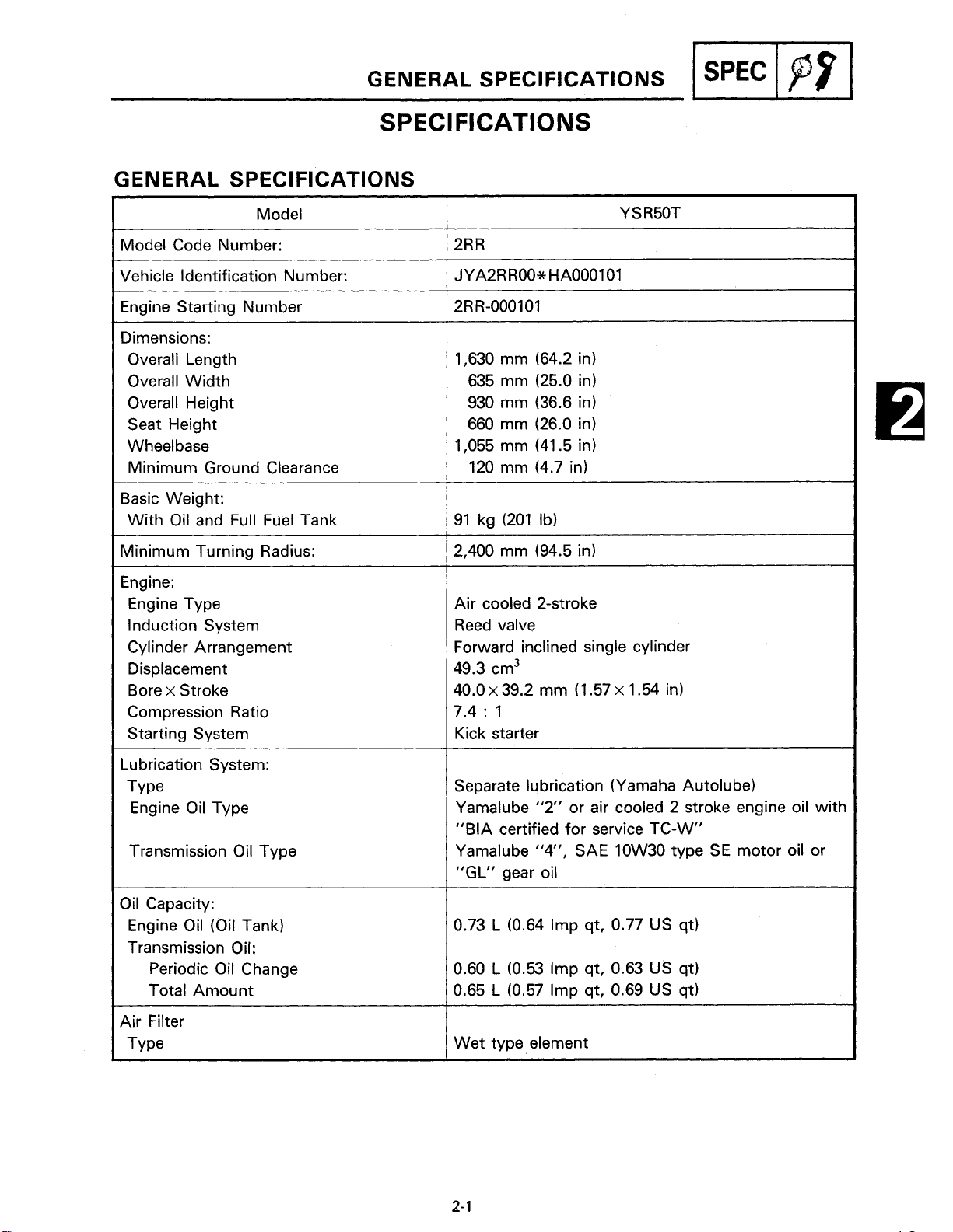
GENERAL SPECIFICATIONS
SPECIFICATIONS
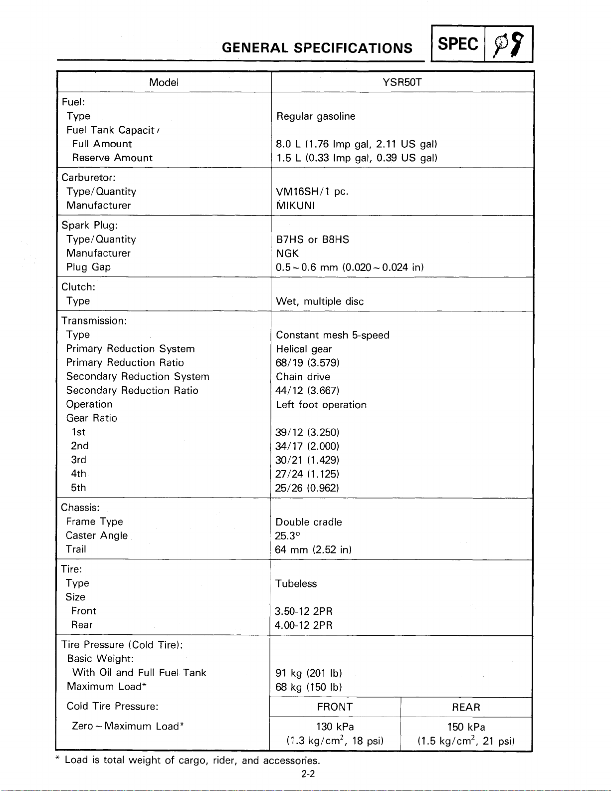
GENERAL SPECIFICATIONS
Model
Model Code Number:
Vehicle Identification Number:
Engine Starting Number
Dimensions:
Overall Length
Overall Width
Overall Height
Seat Height
Wheel base
Minimum Ground Clearance
Basic Weight:
With Oil and Full Fuel Tank
1,630 mm (64.2 in)
635 mm (25.0 in)
930 mm (36.6 in)
660 mm (26.0 in)
1,055 mm (41.5 in)
120 mm (4.7 in)
I
SPEC
/
pf
I
Minimum Turning Radius:
Engine:
Engine Type
Induction System
Cylinder Arrangement
Displacement
x
Bore
Compression Ratio
Starting System
Lubrication System:
TY pe
Engine Oil Type
Transmission Oil Type
Oil Capacity:
Engine Oil (Oil Tank)
Transmission Oil:
Stroke
Periodic Oil Change
Total Amount
2,400 mm (94.5 in)
Air cooled 2-stroke
Reed valve
Forward inclined single cylinder
49.3 cm3
x
40.0
7.4
Kick starter
Separate lubrication (Yamaha Autolube)
0.73
0.60 L (0.53 Imp qt, 0.63 US qt)
0.65
39.2 mm (1.57 x 1.54 in)
:
1
Yamalube
"BIA certified for service TC-W"
Yamalube
"GL"
"2
or air cooled 2 stroke engine oil with
"4,
SAE 10W30 type SE motor oil or
gear oil
L
(0.64 Imp qt, 0.77 US qt)
L
(0.57 Imp qt, 0.69 US qt)
Air Filter
Type
Wet type element
Page 22
Model
Fuel:
TY pe
Fuel Tank Capacit
Full Amount
Reserve Amount
Carburetor:
Type/ Quantity
Manufacturer
Spark Plug:
TypeIQuantity
Manufacturer
Plug Gap
Clutch:
Type
Transmission:
TY pe
Primary Reduction System
Primary Reduction Ratio
Secondary Reduction System
Secondary Reduction Ratio
Operation
Gear Ratio
1 st
2nd
3rd
4th
5th
I
GENERAL SPECIFICATIONS
Regular gasoline
8.0 L (1.76 Imp gal, 2.1 1 US gal)
1.5 L (0.33 Imp gal, 0.39 US gal)
VM16SH/1 pc.
MIKUNI
B7HS or B8HS
NGK
-
0.6 mm (0.020 - 0.024 in)
0.5
Wet, multiple disc
Constant mesh 5-speed
Helical gear
68/19 (3.579)
Chain drive
44/12 (3.667)
Left foot operation
I
SPEC
/
pf
I
Chassis:
Frame Type
Caster Angle
Trail
Tire:
TY pe
Size
Front
Rear
Tire Pressure (Cold Tire):
Basic Weight:
With Oil and Full Fuel Tank
Maximum Load*
Cold Tire Pressure:
-
Zero
*
Load is total weight of cargo, rider, and accessories.
Maximum Load*
Double cradle
25.3'
64 mm (2.52 in)
Tubeless
3.50-12 2PR
4.00-12 2PR
FRONT
2-2
Page 23
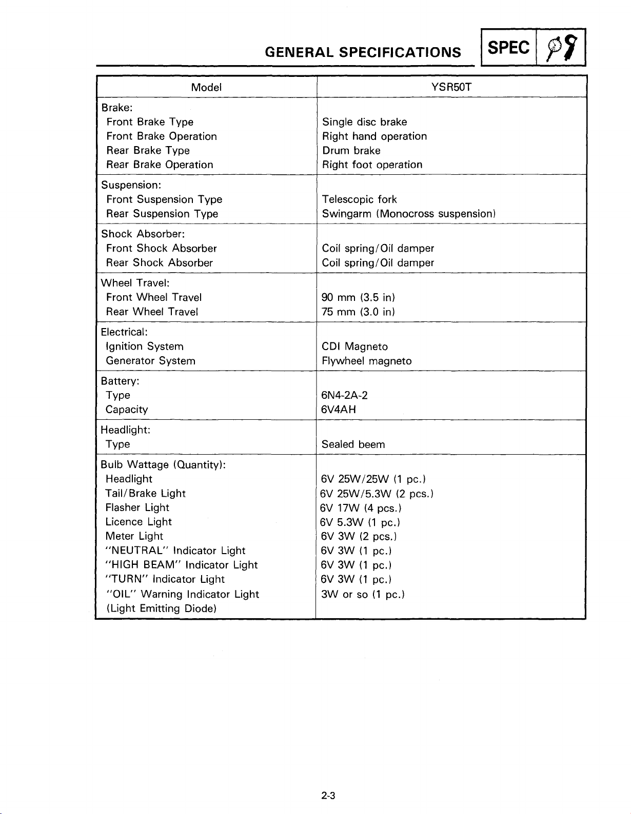
Model
Brake:
Front Brake Type
Front Brake Operation
Rear Brake Type
Rear Brake Operation
Suspension:
Front Suspension Type
Rear Suspension Type
Shock Absorber:
Front Shock Absorber
Rear Shock Absorber
Wheel Travel:
Front Wheel Travel
Rear Wheel Travel
Electrical:
Ignition System
Generator System
GENERAL SPECIFICATIONS
Single disc brake
Right hand operation
Drum brake
Right foot operation
Telescopic fork
Swingarm (Monocross suspension)
Coil springloil damper
Coil springloil damper
90 mm (3.5 in)
75
mm (3.0 in)
CDI Magneto
Flywheel magneto
-1
Battery:
Type
Capacity
Headlight:
TY pe
Bulb Wattage (Quantity):
Headlight
TailIBrake Light
Flasher Light
Licence Light
Meter Light
"NEUTRAL" lndicator Light
"HIGH BEAM" lndicator Light
"TURN" lndicator Light
"OIL" Warning lndicator Light
(Light Emitting Diode)
Sealed beem
Page 24
MAINTENANCE SPECIFICATIONS
MAINTENANCE SPECIFICATIONS
ENGINE
Model
I
SPEC
1
p9
I
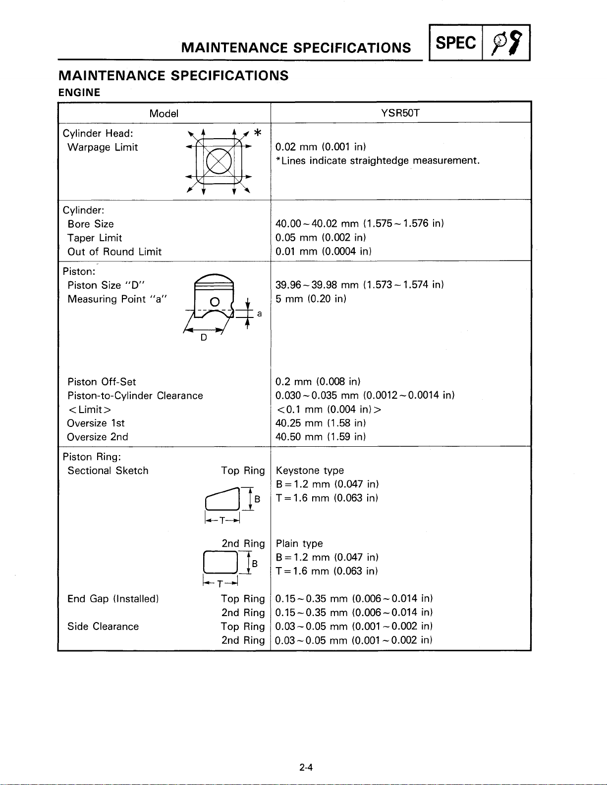
Cylinder Head:
Warpage Limit
Cylinder:
Bore Size
Taper Limit
Out of Round Limit
Piston:
Piston Size
Measuring Point "a"
Piston Off-Set
Piston-to-Cylinder Clearance
<
Limit
Oversize
Oversize
"D"
>
1st
2nd
*
0.02 mm (0.001 in)
"Lines indicate straightedge measurement.
40.00-40.02 mm (1.575- 1.576 in)
0.05 mm (0.002 in)
0.01 mm (0.0004 in)
39.96-39.98 mm (1.573- 1.574 in)
5 mm (0.20 in)
0.2 mm (0.008 in)
-
0.030
<
40.25 mm (1.58 in)
40.50 mm (1.59 in)
0.035 mm (0.0012 - 0.0014 in)
0.1 mm (0.004 in)
>
Piston Ring:
Sectional Sketch Top Ring
OTg
LT~
End Gap (Installed) Top Ring
2nd Ring
Side Clearance Top Ring
2nd Ring
Keystone type
B = 1.2 mm (0.047 in)
=
1.6 mm (0.063 in)
T
Plain type
B
=
1.2 mm (0.047 in)
=
1.6 mm (0.063 in)
T
-
0.15
0.15-0.35 mm (0.006-0.014 in)
0.03-0.05 mm (0.001 -0.002 in)
0.03-0.05 mm (0.001 -0.002 in)
0.35 mm (0.006 - 0.014 in)
Page 25
MAINTENANCE SPECIFICATIONS
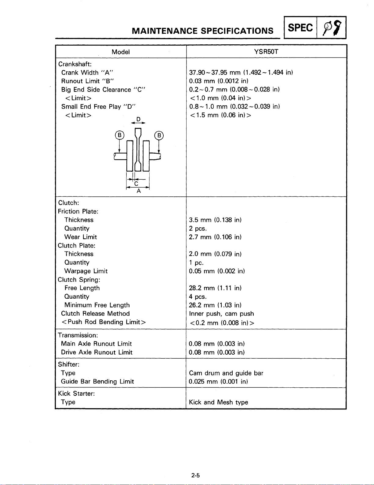
Model
Crankshaft:
Crank Width "A"
Runout Limit "B"
Big End Side Clearance "C"
<
Limit
>
Small End Free Play "D"
<
Limit
>
-
Clutch:
Friction Plate:
Thickness
Quantity
Wear Limit
Clutch Plate:
Thickness
Quantity
Warpage Limit
Clutch Spring:
Free Length
Quantity
Minimum Free Length
Clutch Release Method
<
Push Rod Bending Limit
D
>
I
SPEC
37.90-37.95 mm (1.492- 1.494 in)
0.03 mm (0.0012 in)
-
0.2- 0.7 mm (0.008
<
1.0 mm (0.04 in)
0.8- 1.0 mm (0.032-0.039 in)
<
1.5 mm (0.06 in)
3.5 mm (0.138 in)
2 pcs.
2.7 mm (0.106 in)
2.0 mm (0.079 in)
PC.
1
0.05 mm (0.002 in)
28.2 mm (1.11 in)
4 pcs.
26.2 mm (1.03 in)
Inner push, cam push
~0.2 mm (0.008 in)
0.028 in)
>
>
>
1
pp
I
Transmission:
Main Axle Runout Limit
Drive Axle Runout Limit
Shifter:
TY pe
Guide Bar Bending Limit
Kick Starter:
TY pe
-
0.08 mm (0.003 in)
0.08 mm (0.003 in)
Cam drum and guide bar
0.025 mm (0.001 in)
Kick and Mesh type
Page 26
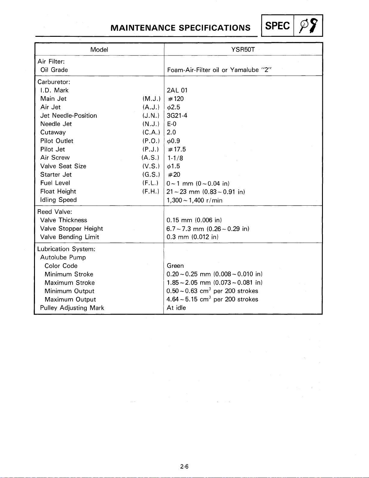
Air Filter:
Oil Grade
Carburetor:
I.D. Mark
Main Jet
Air Jet
Jet Needle-Position
Needle Jet
Cutaway
Pilot Outlet
Pilot Jet
Air Screw
Valve Seat Size
Starter Jet
Fuel Level
Float Height
Idling Speed
Model
MAINTENANCE SPECIFICATIONS
Foam-Air-Filter oil or Yamalube
2AL 01
#
120
42.5
3621 -4
E-0
2.0
40.9
#
17.5
1-118
41.5
#
20
0- 1
mm (0- 0.04 in)
21 -23 mm (0.83 - 0.91 in)
1,300 - 1,400 rlmin
-1
"2"
Reed Valve:
Valve Thickness
Valve Stopper Height
Valve Bending Limit
Lubrication System:
Autolube Pump
Color Code
Minimum Stroke
Maximum Stroke
Minimum Output
Maximum Output
Pulley Adjusting Mark
0.15 mm (0.006 in)
6.7-7.3 mm (0.26- 0.29 in)
0.3 mm (0.012 in)
Green
0.20 - 0.25 mm (0.008 - 0.010 in)
1.85-2.05 mm (0.073-0.081 in)
0.50-0.63 cm3 per 200 strokes
4.64 - 5.15 cm3 per 200 strokes
At idle
Page 27
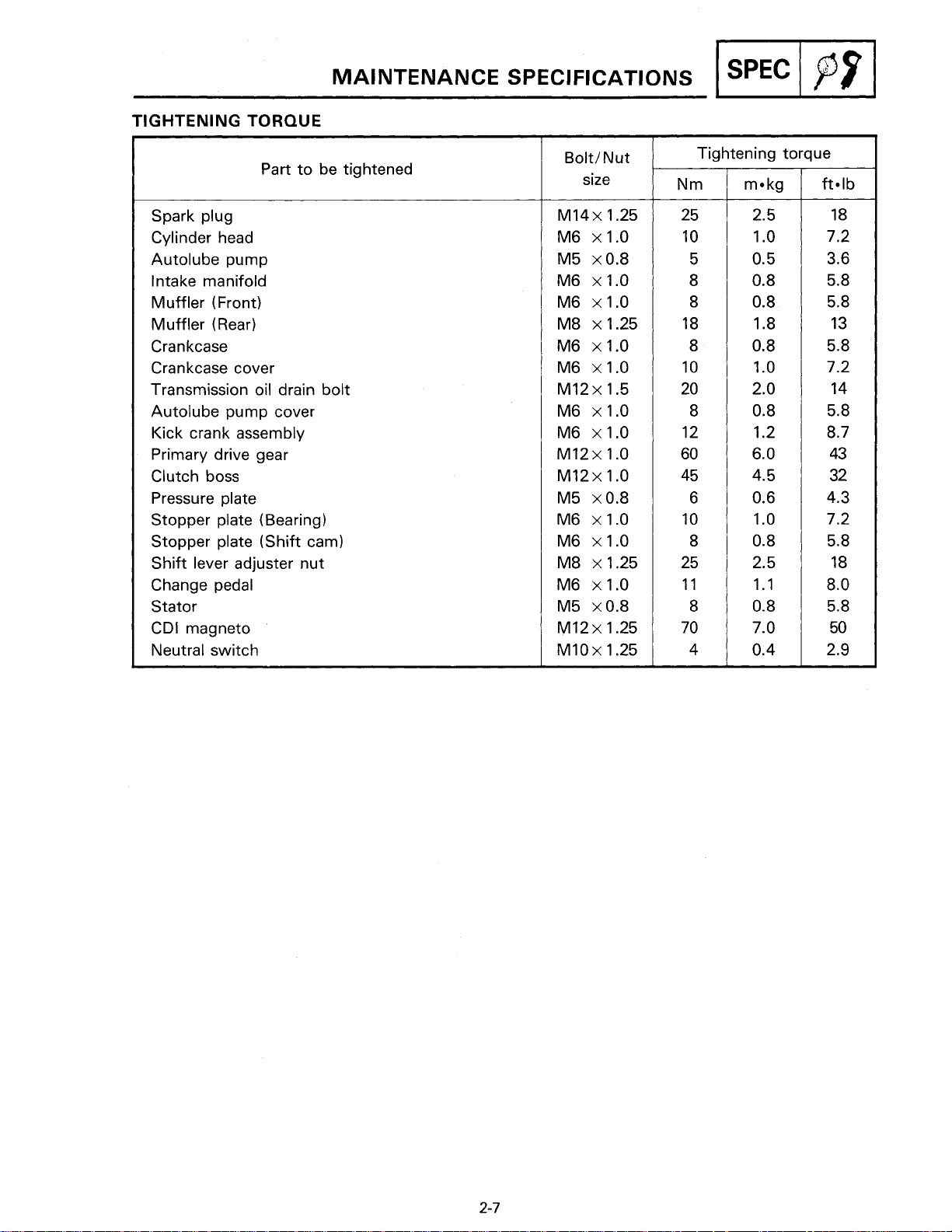
TIGHTENING TORQUE
MAINTENANCE SPECIFICATIONS
I
SPEC
/
p9
I
Part to be tightened
Spark plug
Cylinder head
Autolube pump
Intake manifold
Muffler (Front)
Muffler (Rear)
Crankcase
Crankcase cover
Transmission oil drain bolt
Autolube pump cover
Kick crank assembly
Primary drive gear
Clutch boss
Pressure plate
Stopper plate (Bearing)
Stopper plate (Shift cam)
Shift lever adjuster nut
Change pedal
Stator
CDI magneto
Neutral switch
BoltINut
size
Tightening torque
Page 28
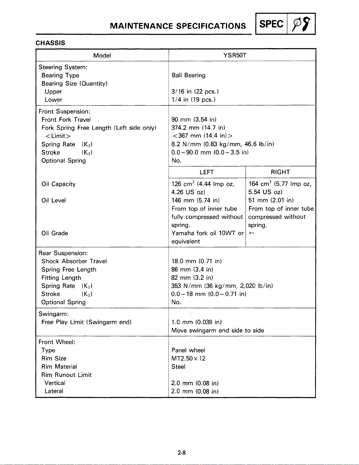
MAINTENANCE SPECIFICATIONS
CHASSIS
Model
Steering System:
Bearing Type
Bearing Size (Quantity)
Upper
Lower
Front Suspension:
Front Fork Travel
Fork Spring Free Length (Left side only)
<
Limit
>
Spring Rate (K1)
Stroke (KI)
Optional Spring
pi+q
Ball Bearing
90 mm (3.54 in)
374.2 mm (14.7 in)
<367 mm (14.4 in)
8.2 Nlmm (0.83 kglmm, 46.6 Iblin)
0.0-90.0 mm (0.0 -3.5 in)
No.
>
Oil Capacity
Oil Level
Oil Grade
3ear Suspension:
Shock Absorber Travel
Spring Free Length
Fitting Length
Spring Rate
Stroke (K1)
Optional Spring
Swingarm:
Free Play Limit (Swingarm end)
Front Wheel:
TY pe
Rim Size
Rim Material
Rim Runout Limit
Vertical
Lateral
(K1)
LEFT
126 cm3 (4.44 Imp oz,
4.26 US oz)
146 mm (5.74 in)
From top of inner tube
fully compressed without
spring.
Yamaha fork oil 10WT or
equivalent
18.0 mm (0.71 in)
86 mm (3.4 in)
82 mm (3.2 in)
353 Nlmm (36 kglmm, 2,020 Iblin)
0.0- 18 mm (0.0-0.71 in)
No.
1.0 mm (0.039 in)
Move
swingarm end side to side
Panel wheel
MT2.50
Steel
2.0 mm (0.08 in)
2.0 mm (0.08 in)
x
12
164 cm3 (5.77 Imp oz,
5.54 US oz)
51 mm (2.01 in)
From top of inner tub(
compressed without
spring.
t
RIGHT
Page 29
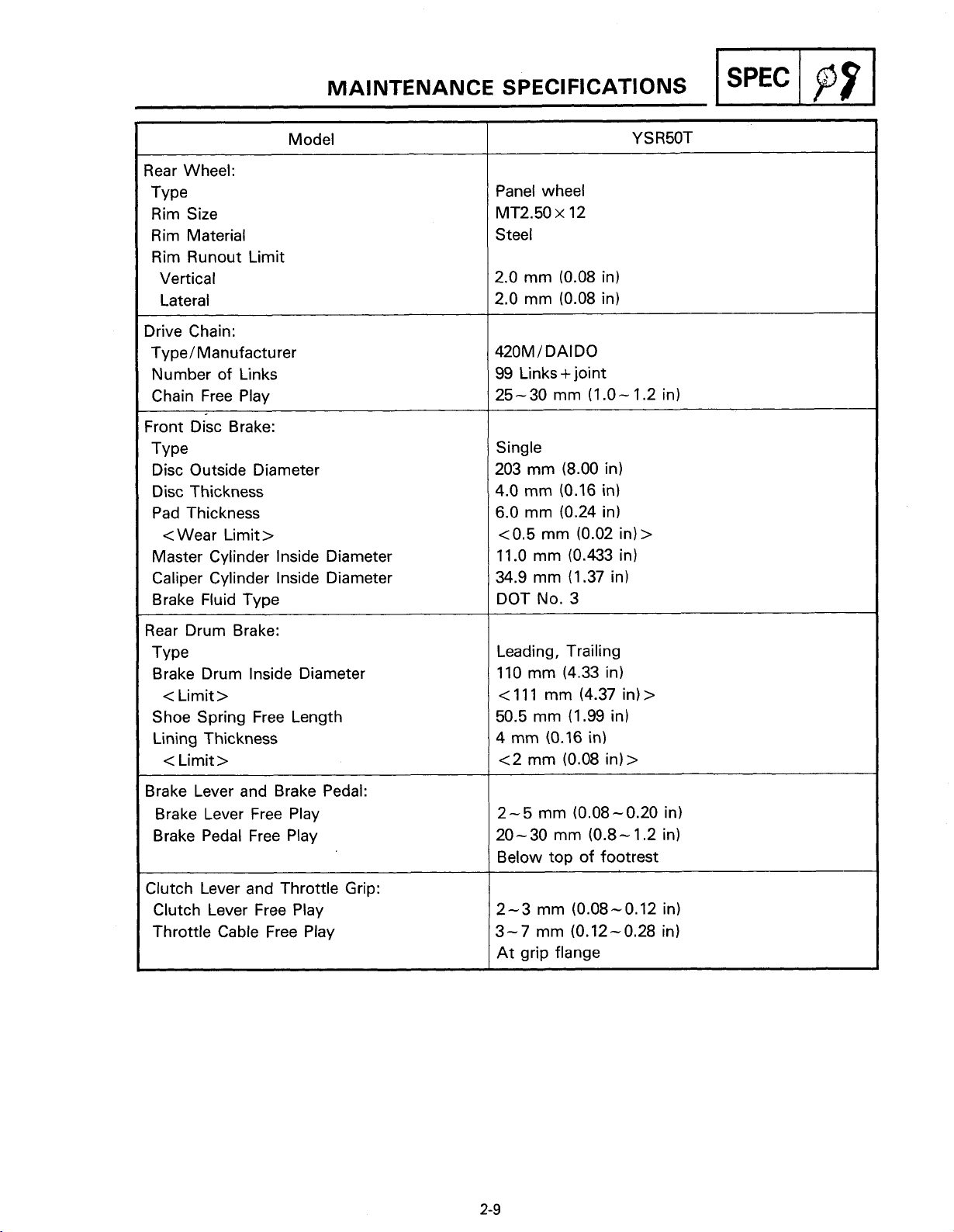
MAINTENANCE SPECIFICATIONS
pqi$q
I
Rear Wheel:
Type
Rim Size
Rim Material
Rim Runout Limit
Vertical
Lateral
Drive Chain:
Type! Manufacturer
Number of Links
Chain Free Play
Front Disc Brake:
TY pe
Disc Outside Diameter
Disc Thickness
Pad Thickness
<Wear Limit
Master Cylinder lnside Diameter
Caliper Cylinder lnside Diameter
Brake Fluid Type
Model
>
Panel wheel
MT2.50
Steel
2.0 mm (0.08 in)
2.0 mm (0.08 in)
420M/ DAIDO
99 Links +joint
25-30 mm (1.0- 1.2 in)
Single
203 mm (8.00 in)
4.0 mm (0.16 in)
6.0 mm (0.24 in)
<
11
34.9 mm (1.37 in)
DOT No.
x
12
0.5 mm (0.02 in)
.O
mm (0.433 in)
3
>
Rear Drum Brake:
TY pe
Brake Drum lnside Diameter
<
Limit
>
Shoe Spring Free Length
Lining Thickness
<
Limit
>
Brake Lever and Brake Pedal:
Brake Lever Free Play
Brake Pedal Free Play
Clutch Lever Free Play
Throttle Cable Free Play
Leading, Trailing
110 mm (4.33 in)
<
11 1 mm (4.37 in)
50.5 mm (1.99 in)
4
mm (0.16 in)
<2 mm (0.08 in)>
2-5 mm (0.08-0.20 in)
20-30 mm (0.8-1.2 in)
Below top of footrest
2-3 mm (0.08-0.12 in)
3-7 mm (0.12-0.28 in)
At grip flange
>
Page 30
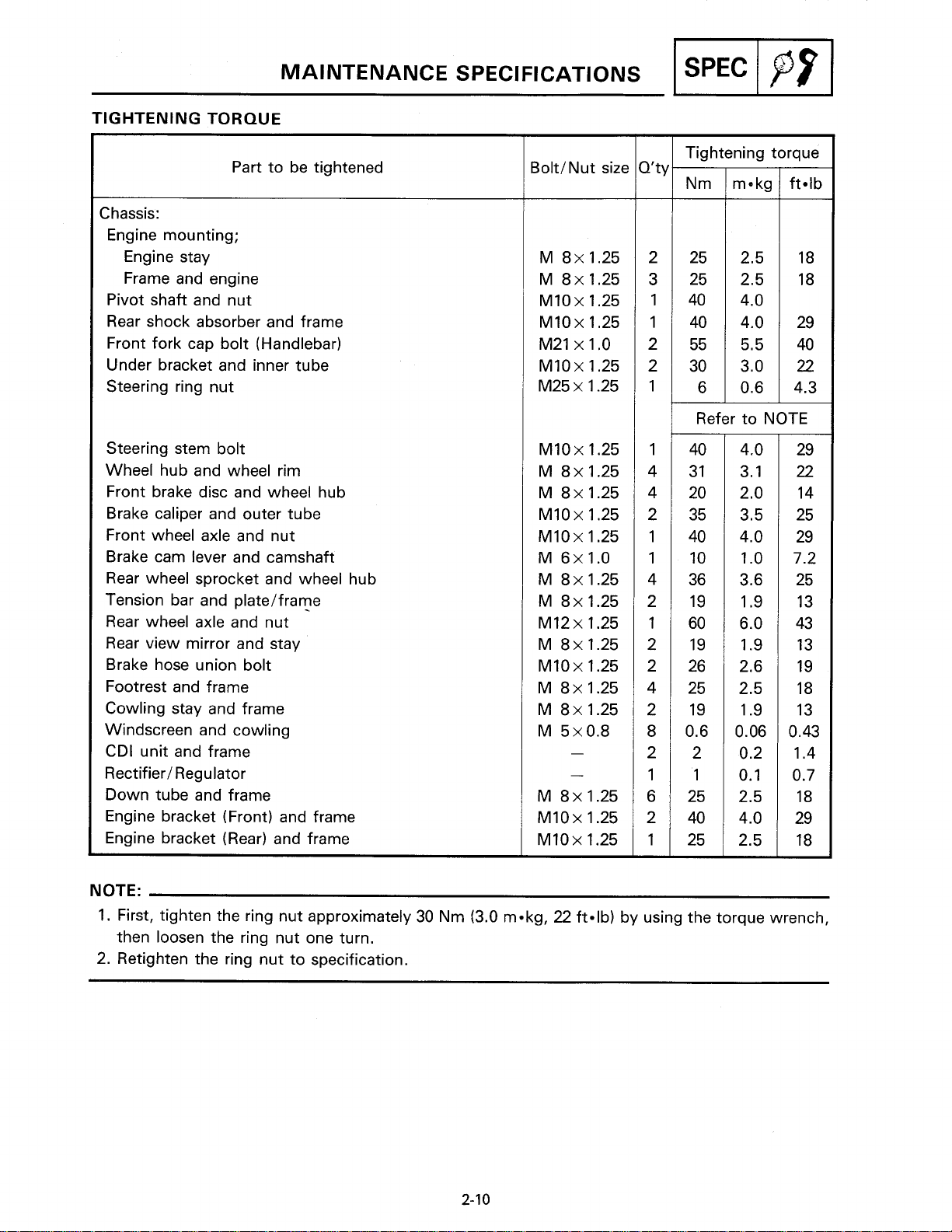
MAINTENANCE SPECIFICATIONS
TIGHTENING
Chassis:
Engine mounting;
Engine stay
Frame and engine
Pivot shaft and nut
Rear shock absorber and frame
Front fork cap bolt (Handlebar)
Under bracket and inner tube
Steering ring nut
Steering stem bolt
Wheel hub and wheel rim
Front brake disc and wheel hub
Brake caliper and outer tube
Front wheel axle and nut
Brake cam lever and camshaft
Rear wheel sprocket and wheel hub
Tension bar and
Rear wheel axle and nut
Rear view mirror and stay
Brake hose union bolt
Footrest and frame
Cowling stay and frame
Windscreen and cowling
CDI unit and frame
Rectifier1 Regulator
Down tube and frame
Engine bracket (Front) and frame
Engine bracket (Rear) and frame
TORQUE
Part to be tightened
platelframe
BoltlNut size
Tightening torque
ft-lb
Refer to NOTE
NOTE:
1.
First, tighten the ring nut approximately 30 Nm (3.0 m-kg,
then loosen the ring nut one turn.
2.
Retighten the ring nut to specification.
22
ft-lb) by using the torque wrench,
Page 31

ELECTRICAL
MAINTENANCE SPECIFICATIONS
-1
--
-
-
Voltage:
Ignition System:
Ignition Timing (B.T. D.C.)
Advancer Type
Model
22O at 5,000 rlmin
Electrical type
01234
C.D.I.:
Magneto ModelIManufacturer
C.
D. I. Unit Model/ Manufacturer
Pickup Coil Resistance (Color)
Source Coil Resistance (Color)
Ignition Coil:
ModelIManufacturer
Minimum Spark Gap
Primary Coil Resistance
Secondary Coil Resistance
Spark Plug Cap:
TY pe
Plug Cap Resistance
Engine
2RRlYAMAHA
2GXlYAMAHA
16-240 at 20°C (68OF)
(WhiteIRed- Black)
264- 396fl at 20°C (68OF)
-
(Black/ Red
2JNlYAMAHA
6 mm (0.24 in)
0.7- 1.1Q at 20°C (68OF)
5.7-8.5kQ at 20°C (68OF)
Resin Type
4-6kQ at 20°C (68OF)
Black)
Page 32

MAINTENANCE SPECIFICATIONS
-1
-
Charging System:
C.D.I. Magneto:
ModelIManufacturer
Charging Coil Resistance (Color)
Standard Output
Model
Y S R50T
I
Flywheel Magneto
2RRlYAMAHA
0.24-0.36Q at 20°C (68OF) (White- Black)
7.4-8.2V at 5,000 rlmin
Lighting Coil Resistance (Color)
Standard Output
Voltage Regulator:
ModelIManufacturer
I
Rectifier:
ModelIManufacturer
Capacity
Withstand Voltage
Battery:
Specific Gravity
Horn:
TY pe
Quantity
Model1 Manufacturer
Maximum Amperage
Engine Speed
(
x
1,000
rlmin)
0.16-0.24Q at 20°C (68OF) (YellowIRed- Black)
6.2-7.2V at 3,000 rlmin or more
Plane Type
1 PC.
GF-12lNIKKO
1.5A
Page 33

Model
Flasher Relay:
Type
ModelIManufacturer
Self Cancelling Device
Flasher Frequency
Wattage
Oil Level Switch:
ModelIManufacturer
Curcuit Breaker:
Type
Curcuit (Fuse):
"MAIN"
MAINTENANCE SPECIFICATIONS
Condenser Type
FZ636SDlNIPPON DENS0
No
-
95
75
17W
Fuse
cycles1 min
x
2
+
3W
(6V)
I
SPEC
I
p?
I
Page 34

GENERAL TORQUE SPECIFICATIONS1
DEFINITION OF UNITS
GENERAL TORQUE
SPECIFICATIONS
This chart specifies torque for standard fasteners
with standard I.S.O. pitch threads. Torque specifi-
cations for special components or assemblies are
included in the applicable sections of this book.
To avoid
blies in a crisscross fashion, in progressive stages,
until full torque is reached. Unless otherwise
specified, torque specifications call for clean, dry
threads. Components should be at room temperature.
warpage, tighten multi-fastener assem-
A
(Nut) (Bolt)
B
General torque
specifications
Nm
1
m-kg / ft-lb
,
I
A: Distance across flats
B:
Outside thread diameter
DEFINITION OF UNITS
Unit
mm
cm
kg
N
Nm
m-kg
Pa
N/mm
L
cm3
rlmin
millimeter
centimeter
kilogram
Newton
Newton meter
Meter kilogram
Pascal
Newton per millimeter
Liter
Cubic centimeter
Rotation per minute
Read
Definition
meter
meter
lo3
gram
1 kg
x
m /sec2
Nxm
m
x
kg
~/m~
N/mm
-
-
Measure
Length
Length
Weight
Force
Torque
Torque
Pressure
Spring rate
Volume or capacity
Engine speed
Page 35

LUBRlCATlON POINTS AND LUBRICANT TYPE
LUBRICATION POINTS AND LUBRICANT TYPE
ENGINE
I
SPEC
1
pf
I
I
I
Oil seal lip
O-ring
I
Small end1Big end bearing
Bearing
Piston ring
I
Piston
Cylinder inner surface
Piston pin
I
Kick axle
Primary drivenldrive gear
Push rod
I
Push lever
PinionIWheel gears
Collar (Drive axle)
I
Guide bar (Shift fork)
Lubrication Points (Part name)
I
Lubricant Type
--.~SI
-=a&
-IQ
-IQ
-+a
A=
-4
-la
Shift shaft
Shift cam
CHASSIS
Lubrication Points (Part name)
Steering UpperlLower balls
FrontIRear wheel oil seal lip
Brake cam shaft
Speedometer gear unitloil seal
Brake pedal pivot
Rear shock absorber collar
Handlebar (Right) end
Sidestand pivot
Footrest pivot
Clutch lever
Brake lever pivot
pivotlcable end
1
1
1
-la
-a
Lubricant Type
A=
-5
I
I
-=
-?as4
-+a
I
-a
-=
-la
-IQ
-IQ
-4
Pin (Rear shock absorber)
Pivot shaft
-=
--=&
2-15
Page 36

CABLE
ROUTING
I
SPEC
/
p9
I
CABLE
a
Handlebar switch (Right) lead
@
Main switch lead
@
Clutch cable
@
Handlebar switch (Left) lead
@
Clamp
@
Throttle cable
a
Front brake hose
ROUTING
Page 37

CABLE
ROUTING
I
SPEC
I
p9
I
CABLE
@
Headlight lead
@
Spark plug lead
@
Clutch cable
@
Horn lead
@
Sidestand switch lead
@
Band
a
Cable holder
@
Speedometer cable
@
Meter light lead
ROUTING
Pass the speedometer cable through the cable
holder.
Page 38

CABLE
ROUTING
I
SPEC
1
pp
1
CABLE
Front brake hose
Clamp
Cable guide
Oil hose
@
Oil pump cable
@
Oil delivery hose
@
Fuel tank breather hose @ Taillbrake light lead
@
Wireharness
ROUTING
@
Carburetor breather hose
@
Carburetor air vent hose
0
CDl magneto lead
@
Battery breather hose
@
Rear brake switch lead
@
Band
Clamp the brake hose.
1Si]
Pass the battery breather hose through the
hole on the rear fender.
Page 39

CABLE
ROUTING
-1
CABLE
a
Clamp
a
Band
@
Throttle cable
@
Front brake hose
@
Brake switch lead
@
RectifierIRegulator @ Ignition coil hose.
a
Main switch lead
ROUTING
@
@
0
@
@
@
@
Wireharness
Clutch cable hole on the frame.
Sidestand switch lead
Handlebar switch (Left) lead
Spark plug lead
Oil tank breather hose
Oil level switch
IB]
Pass the oil tank breather hose through the
Pass the main switch and brake switch lead in-
side of the oil tank cap
Pass the sidestand lead above the Y.E.I.S.
Page 40

CABLE ROUTING
@
Band
@
Cable guide
@
Rear flasher light (Right) lead
@
Taillight lead
@
Rear flasher light (Left) lead
@
Battery negative
a
Battery positive
@
Battery
@
Flasher relay
@
CDI unit
(
-
)
lead
(
+
)
lead
CABLE
CB]
ROUTING
Pass the wireharness, flasher light lead and
battery breather hose through the guide.
Pass the flasher light lead through the guide.
-1
Page 41

lNTRODUCTlONlPERlODlC MAINTENANCE1
LUBRICATION INTERVALS
lNSP
1
I
PERIODIC INSPECTION AND ADJUSTMENT
INTRODUCTION
This chapter includes all information necessary to perform recommended inspections and adjustments.
These preventive maintenance procedures, if followed, will ensure more reliable vehicle operation and
a longer service life. The need for costly overhaul work will be greatly reduced. This information ap-
plies to vehicles already in service as well as new vehicles that are being prepared for sale. All service
technicians should be familiar with this entire chapter.
PERIODIC MAINTENANCEILUBRICATION INTERVALS Unit: km (mi)
I
ITEM
I
Spark plug(s)
I
Air filter"
Carburetor*
Fuel line*
Wheels*
Wheel bearings*
I
Steering bearing*
Front forks*
absorber*
Drive chain
Fittings1 Fasteners*
I
Sidestand switch*
Battery*
REMARKS
Check condition. Clean or replace if
necessarv.
Clean. Replace if necessary.
Check idle speedlstarter operation.
Adjust if necessary.
Check fuel hose for cracks or damage.
Replace if necessary.
Check oil levelloil leakage.
Correct if necessary.
Replace every 12,000 (8,000) or 24 months
(Warm engine before draining.
Check operation. Correct if necessary.
Air bleeding.
Check operation/fluid IeakageISee NOTE.
Correct if necessary (front). Brake*
Check operation. Adjust if necessary (rear).
Check operation. Adiust if necessarv.
Check
Repair if necessary.
Check bearings assembly for looseness/
damage. Replace if damaged.
Check bearings assembly for looseness.
Correct if necessary.
Moderately repack every 24,000 (16,000)
or 24 months.**
Check operationloil leakage.
Repair if necessary.
Check operationloil leakage.
Repair if necessary.
Check chain slacklalignment.
Adjust if necessary. Clean and lube.
Check all chassis fittings and fasteners.
Correct if necessary.
Check operation. Repair if necessary.
Check operation.
Clean or replace if necessary.
Check specific gravity.
Check breather pipe for proper operation.
Correct if necessary.
balanceldamagelrunout.
1
BREAK-IN
1,000 (600) (2,000) or (4,000) or
REPLACE
7
1
6 months 1 12 months
EVERY 500
0
EVERY
6,000
0
(300)
It is recommended that these items be serviced by a Yamaha dealer or other qualified mechanic.
*:
**:
Medium weight wheel bearing grease. (bearing type)
3-1
Page 42

INTRODUCTION/PERIODIC MAINTENANCE1
LUBRICATION INTERVALS
NOTE:
Brake system:
1.
When disassembling the master cylinder or caliper cylinder, replace the brake fluid. Normally check
the brake fluid level and add the fluid as required.
2.
We recommend that, on the inner parts of the master cylinder and caliper cylinder, replace the
oil seals every two years.
3.
We recommend that, replace the brake hoses every four years, or if cracked or damaged.
Page 43

Page 44

"Front seat
@Side cover
everse removal ste
@
@
a
and
warm
it up.
@Engine idle speed
ut
of specification* Adjust.
@Engine idle speed
p screw
in
or out un-
Page 45

.
Install:
efore adjusting throttle ca le free play, engine
be
idle speed should
1.
Check:
@Throttle cable free
adjusted.
play
@
2.
Adjust:
@Turn the adjuster
tle cable free
pl
or out
until the cor-
1.
Remove:
Lower cowling
Page 46

e
pump
Check:
~Aiignmeni
mark
cover
a
9Tighten
P
5.
Install:
the locknut.
autol lube
@Lower cowling
pum
r
out until the
pP
ali
,
..
-
Page 47

tart
the
engine
gine the moment that the adjus
moves out to its
5.
Measure:
ut
of speci3icatioi~-~Adjus-t~
Measure ?he
between the raised boss
adjusting pulley
and
warm
the engine at idle
g
plate carefully.
limit.
gap
with the Thickness gauge
an
the adjusting plate
it
up.
@
on the pump
-
a.
@Autolube
pump
minimum
stroke
stroke
is
increase
Page 48

@Install the adjustin
locknut.
7.
Install:
.
Air
bleed:
appear.
@When air bubbles are expelled completely,
tighten the bleed screw.
damaged, replace with a new
one.
Page 49

4.
Air bleed:
ump
distributor andlor delivery
hose
:
It
is
difficult
maximum.
5.
Install:
Q
Lower
to
bleed
urnp
cowlin
-
the
stroke
--
distri
at
a
4
rn
PA
'1.
Remove:
Page 50

4.
Inspect:
@Electrode
@Insulator
Abnormal coIor-9
orrnal color
5.
Clean the spark
er or wire brus
. Measure:
sf
specification-.
ut
7.
Tighten:
efore
installing a s ark plug, clean the
gasket and
OTE:
-.....-
Finger-tighten
specifics
to
cisn.
a
is
a medium-$0-light tan color.
or Feeler Gau
auge
Wegap.
plug
surfaces.
--,
the
spark
dug(~) befcwe rorquing
--.--
-
--
N
TBMINNG
Adjustment free.
E
Olk
LEVEL
1.
Check:
@Oil
level
31
level
low-+Add
il
Tank
CHECK
CHECK
sufficient
Capacity:
oil.
Page 51

"OIL" warning
indicator
light
A
1.
Place the motorcycle on a level surface
warm
2.
Stop the engine and remove the oil filler
up
the engine for several minutes.
and
cap.
Page 52

false readings.
4.
Inspect:
il
level should
b
A
he engine for several minutes an
stop the engine.
2.
Place an oil pan under the engine.
rain the engine
oil.
Page 53

.
Install:
.
Fill:
7.
Install:
@
Loosen the locknuts
adjusters
free play is obtained.
@.
@
in or out until the
5-
14
ten the locknuts.
Page 54

~Clutcch
push
lever free play
tighten
the locknut while hoiding the
juster.
5.
Install:
@Flywheel magneto cover
"Lower cowling
6.
Adjust:
@Clutch cable free play
efer
to
@
Front seat
"Free
play adjustment" section.
ad-
Page 55

2.
Turn
the fuel cock to
"
"Fenel
4.
Remove:
tank
ir
filter cover
@
@
ever operate the
element removed.
air to enter, causin
withaut
solvent.
the filter
Clean:
@Air
filter element
nt gently, but thoroughly in
en
This
ine
with
the
will
alisw unfiltered
id
wear
will
affect cavbu-
uewt
poor perfor-
overheating.
ne
air
and
filter
possi-
Page 56

@Squeeze the excess solvent out of the element
and let dry.
r-filter oil or Vamalu
to the element.
out the excess oil.
;;
The
element should be wet
ut
not dripping.
@Air
filter case cover
4
'1.
Install:
@Fuel tank
Front seat
cSide cover
2.
Inspect:
@Carburetor joint
@
"Lower cowl
Page 57

"Lower cowl
@bower cowling
.
Install:
@lower cowling
1.
Check:
rake lever free play
ut
of specification+lnspect the brake
section.
@
Page 58

REA
1.
Check:
Out
free
edal
of
specification-AcdjuS
play
ENT
@
Adjustment
@Turn
BRAKE
1.
2.
the adjuste
fied
free
FLUID
Make
sure
by
turning
1nspecr:
oBrake
Fluid
a+~eplenisk.
Recornmewdad
play
the
fluid
lwei
st8
is
obtained.
!
the
handlebars.
level
is
under
in
or
out
r
"L
WER"
Brake
until
top
FBui
the
spsci-
is
horimontaal
level
I
i
line
I
rake
pRasPie
---
fluid
parts.
may
AGway
erode
painted
surfaces
-
or
Page 59

INSPECTIOPJ
1.
Activate the brake lever,
2.
Inspect:
r
@
2.
Inspect:
ar indicator
cator at wear limit line
brake shoes.
@
almost contacts brake
LIGHT
AICE
TE:
The
brake light switch
of
the brake pe
Proper adjustment is achieved when the
light comes on just before the brake begins to
effect.
it
that
does not rotate and turn the adjusting
Q.
nut
SbVITCH
-
is
operated
e switch body
ADJUSTMENT
--
by
movemenu
a
with your &an
bralee
-
take
1.
Inspect:
rack/ Damage/
Fluid
lea
Page 60

andlor adjust the chain slack with the rear wheel
in this "tightest"
I.
Check:
rive chain slack
ut of specification-tAdjcest.
@
is
slack
alignment.)
obtained
Page 61

eTighten the nut ( ear wheel axle)
@Insert a new cotter pin.
3-21
center rollers.
2.
To clean the
machine,
9.
Remove:
bower cowling
2.
Elevate the front wheel
chain,
dip
it
in solvent, an
under the engine.
remove 'he
by
placing a suitable
Page 62

3.
Check:
Grasp
rock
the
bottom
the
fork
assembly
seness-Adjust steerin
o$
the
back
forks
and
and
forth.
gently
oRstighten
Avoid
r
--
5.
Install:
Lower
"re
ring
nut
over-tightening.
- - -
cowling
using
-
,
the
--
Ring
Nclr
, ,
.
,
Page 63

TlRE INSPECTION
TlRE INSPECTION
Do not attempt to use tubeless tires on a
wheel designed for tube type tires only. Tire
failure and personal injury may result from
sudden deflation.
I
wheel
I
Tube type 1 Tube type only
I
Tubeless ( Tube type or tubeless
Be sure to install the correct tube when using tube type tires.
1.
Measure:
*Tire pressure
Out of specification-+Adjust.
I
lml
Tire
INSP
I
I
I
I
Tire inflation pressure should be checked and
adjusted when the temperature of the tire
equals the ambient air temperature. Tire inflation pressure must be adjusted according
to total weight of cargo, rider, passenger,
and accessories (fairing, saddlebags, etc. if
approved for this model), and vehicle speed.
Basic weight:
With oil and full
fuel tank
I
Maximum load*
I
Cold tire Dressure
Zero - Maximum 130 kPa 150 kPa
load*
*Load is the total weightof cargo, rider, and
accessories.
2.
Inspect:
*Tire surfaces
Wear/ Damage-+Replace.
/
I
1
68
kg (150 Ib)
Front
(1.3 kg/cm2, (1.5 kg/cm2,
18 psi1 21 psi)
/
Rear
I
I
I
Minimum Tire Tread Depth:
(Front and Rear)
@
Tread depth
a
Side wall
@
Wear indicator
Page 64

WHEEL INSPECTIONICABLE INSPECTION AND
LUBRICATION
WHEEL INSPECTION
1.
Inspect:
Wheels
Damage/ Bends* Replace.
NOTE:
Always balance the wheel when a tire or wheel
has been changed or replaced.
Never attempt even small repairs to the
wheel.
lNSP
AD
J
2.
Tighten:
*Valve stem locknut
Ride conservatively after installing a tire to
allow
CABLE INSPECTION AND LUBRICATION
Damaged cable sheath may cause corrosion
and interfere with the cable movement. An
unsafe condition may result so replace such
cable as soon as possible.
it
to seat itself properly on the rim.
1.
Inspect:
*Cable sheath
Damaged Replace.
Page 65

CABLE INSPECTION AND LUBRICATIONILEVER AND
PEDAL LUBRICATIONISIDESTAND LUBRICATION
2.
Check:
@Cable operation
Unsmooth operation* Lubricate.
Recommended Lubricant:
Yamaha Chain and Cable Lube
or SAE
NOTE:
Hold cable end high and apply several drops of
lubricant to cable.
10W30
Motor Oil
LEVER AND PEDAL LUBRICATION
Lubricate pivoting parts of each lever and pedal.
Recommended Lubricant:
Yamaha Chain and Cable Lube
or SAE
SIDESTAND LUBRICATION
Lubricate the sidestand at pivot points.
Recommended Lubricant:
Yamaha Chain and Cable Lube
or SAE
10W30
10W30
Motor Oil
Motor Oil
Page 66

1.
Remove:
@Front seat
@Side cover
Refer to
2.
Inspect:
Fluid level should be between upper
lower
Incorrect-. Refill.
3.
Inspect:
@Battery terminal
Dirty terminal-Clean with wire brush,
Poor connection+Correct.
:--
After cleaning the terminals, apply grease lightly
to the terminals.
"'SIDE
@
level marks.
COVER" section
a
and
--------
4.
Connect:
@Breather hose
Be sure the hose is properly attached and
routed.
@
Pass the breather hose into the
5.
Inspect:
@Breather hose
Obstruction-+ Remove.
Damage-+ Replace.
clamp.
6.
Check:
@Specific gravity
Less than 11.280-.Recharge battery.
Page 67

Replace the battery if:
Battery voltage will not rise to a specific value
or bubbles fail to rise even after many hours
of charging.
*Sulfation of one or more cells occurs, as in-
dicated by the plates turning white, or an accumulation of material exists in the bottom
of the cell.
*Specific gravity readings after a long, slow
charge indicate one cell to be lower than the
rest.
*Warpage or buckling of plates or insulators
is evident.
Always charge a new battery before using
it
to ensure maximum performance.
Battery electrolyte is dangerous;
it
contains
sulfuric acid and therefore is poisonous and
highly caustic.
Always follow these preventive measures:
*Avoid bodily contact with electrolyte as
can cause severe burns or permanent eye
injury.
*Wear protective eye gear when handling or
working near batteries.
Antidote (EXTERNAL):
*SKIN- Flush with water.
15
*EYES-Flush with water for
minutes and
get immediate medical attention.
Antidote (INTERNAL):
*Drink large quantities of water of milk. Fol-
low with milk of magnesia, beaten egg, or
vegetable oil. Get immediate medical attention.
Batteries also generate explosive hydrogen
gas, therefore you should always follow
these preventive measures:
*Charge batteries in a well-ventilated area.
*Keep batteries away from fire, sparks,
or
open flames (e.g., welding equipment,
lighted cigarettes,
etc.)
it
Page 68

inspection
@Connect the Pocket Tester to the fuse and
check
steps:
it
for continuity.
-
Set the tester selector to
"Q
x
1"
position.
elf the tester is indicated at
blown, replace
4.
Replace:
@Blown fuse
@Turn off ignition and the circuit.
a
elnstall
@If
fuse blows immediately again, check circuit
new fuse of proper amperage.
it.
3-28
a.
The fuse is
Page 69

'I.
Adjust:
@Headlight beam (Vertical)
2.
Adjust
@Headlight beam (Horizontal)
T
@Lower cowling
*Flasher lights (Left and right)
sflasher light stay
Refer to "COWLINGS" section.
2.
Remove:
@Headlight
3
Install:
@
@Headlight (New)
Install:
@Flasher light stay
@Flasher lights (Left and right)
@Lower cowling
Adjust:
@Headlight beam
Refer to "HEADLIGHT BEAM ADJUST-
MENT"
section.
Page 70

Page 71

@Autolube pump
@Transmission oil
section.
@Front seat
section.
'1.
Turn
the fuel cock to
connect the
fuel
"
hose
FF"
position and
@.
dis-
2.
Remove:
@Fuel tank
Page 72

VAL
U
@Autolube pump cover
@Autolube pump cable
@Oil
hose
a
Plug the oil hose
end
@
with a suitable screw.
Page 73

eNecatral switch leads
crankcase
oGasket (Crankcase
RBVE
cwim
Loosen:
adjuster
2.
Push
forward
drive
chain.
cover (Left)
@
a
cover
t
e
rear
-
wheel
Left)
to
loosen the
Page 74

.
Place
a
suitable
stand
under
the
engine.
Page 75

Q
Lower cowlin
0Muffler
2.
Remove:
~Gaske?
cylinder
gasket
~Intake rnanifoid
(Cylinder head)
@J
(Cylinder)
@
@
ing
into crankcase cavity.
--
pin circlip, cover crank-
Page 76

out.
CLUTCH
TE:
Bower
2,
IYsi-xve:
8
Boles
^Springs
AND
cowl
(Pressure
(Pressure
PRIMARY
-
plate)
plats)
-
.:,
--
-
Page 77

4.
Remove:
Use the Universal Clutch
the
clutch
lace a folded rag
primary drive gear and driven gear.
boss.
imary drive gear)
a
between
Holder
@
the
teeth of the
Page 78

[owing parts.
1.
Unhook the sprin
mounted, the
maintained by removing the
cable and hoses
kick
axle
and
m
kick
fol-
@Kick
axle assembly
a
Page 79

NOTE:
With
the
engine
be
mainlained by
Lower
covviiiyj
-
1.
Remove:
mounted,
removing
---
Rotor
the
the
-..--
CDB
ma
fcallo
Holder
-
a
to
-.
hold
Page 80

Use
rotor.
the
Flywheel
Puller
a
to
remove
the
loosened.
hift
cam
stopper)
ttern, loosen
them
all
after
screws
all
are
Page 81

NOTE:
sure the
"14s
front engine mounting
and
Use
only
tap
a;qd
separate
pressure
start
check
Do
-
--
hten
the
tool holdin bolts, but make
fool
body
one
screw
pressure
shift cam.
soft
on asinforced
sn
gasket mati g surface.
carsffuiiy. Make sure
over.
For
not
hammer
evenly.
of8
BB
a
remaisping
force.
is
a
plied, alternately tap
to
If
the
push
the
--
-=-
TRANSMQSSBObJ,
-
P
is parallel
may
be
backed
boss,
transmission shafts,
tap
on
the
ortiona
the
one
wad
"'hangs
screw, realign,
eases
do
case screw
SHiFTER
with
case
of
case.
Wdwk
not
---
AND
the
ease,
out
slightly
on
half. Tap
Do
s!owOy
ease
hahes
up,"
separate,
~t.
fitting.
Ef
the
not
take
and
Remove
the
transmission
assern
Page 82

Page 83

INSPECTION AND REPAIR
INSPECTION AND REPAIR
CYLINDER HEAD
1.
Eliminate:
.Carbon deposits
Use a rounded scraper.
NOTE:
Take care to avoid damaging the spark plug
threads. Do not use a sharp instrument. Avoid
scratching the aluminum.
-
--
-
2.
Measure:
.Cylinder tiead warpage
Out of
Warpage measurement and resurfacement steps:
.Attach a straight edge
gauge
.Measure the warpage.
.If the warpage is out of specification, resur-
face the cylinder head.
Place a
surface plate, and resurface the head using
a figure-eight sanding pattern.
NOTE:
Rotate the head several times to avoid remov-
ing too much material from one side.
specification-+Resurface.
Warpage Limit:
0.02
mm
(0.001
@
on the cylinder head.
400
-
600
grit wet sandpaper on the
I
ENG
-
--
in)
@
and a thickness
/
~o)(
CYLINDER AND PISTON
1.
Eliminate:
.Carbon deposits
From the piston crown and ring grooves.
2.
Eliminate:
.Score marks and lacquer deposits
From the sides of piston.
Use a
NOTE:
Sand in a crisscross pattern. Do not sand exces-
sively.
3.
Inspect:
.Piston wall
600-800
grit wet sandpaper.
Page 84

INSPECTION AND REPAIR
4.
Remove:
.Carbon deposits
Use a rounded scraper.
5. Measure:
*Piston-to-cylinder clearance
Piston-to-cylinder clearance measurement
steps:
First Step:
Measure the cylinder bore "C" with a Cylinder
Bore Gauge.
NOTE:
Measure the cylinder bore "C" in parallel to and
at
right angles to the crankshaft. Then, find the
average of the measurements.
-1
Standard Wear Limit
"C"
TaperJ1T"
)ut of Round 0.01 mm
"R"
C=
Maximum D
T= (Maximum Dl, or D2)-
(Maximum Ds or D6)
R = (Maximum Dl,
(Minimum
.If out of specification, rebore or replace
cylinder, and replace piston and piston rings
as a set.
Second Step:
@Measure the piston skirt diameter
a micrometer.
a
5
mm
edge.
(0.20
1
1
in)
-
-
D3
or D5)-
Dz
D4 or D6)
from the piston bottom
0.05 mm
/
10.0019 in)
1
10.0004 in1
"P"
with
Page 85

INSPECTION AND REPAIR
I
ENG
I
\j(
Piston size
fz
"
-
-
39.96-39.98
-
(1.573
mm
40.25
40.50
mm
--
=
Standard
Oversize 1
Oversize
*If out of specification, replace piston and
piston rings as a set.
Third Step:
*Calculate the piston-to-cylinder clearance with
following formula:
Piston-to-cylinder Clearance
Cylinder Bore "C"
Piston Skirt Diameter "P"
*If out of specification, rebore or replace
cylinder, and replace piston and piston rings
as a set.
Piston-to-cylinder Clearance:
2
P
mm
1.574 in)
(1.58 in)
(1.59 in)
(0.0012 - 0.0014
Limit:
PISTON RINGS
1.
Measure:
*Side clearance
Out of
rings.
Use a Feeler Gauge
Clearance 0.03-0.05
0.1
specification+Replace piston and/or
mm
in)
(0.004
in)
@.
0.03-0.05
(0.001 - 0.002 in)
mm
mm
Page 86

INSPECTION AND REPAIR
2.
Install:
*Piston ring
lnto the cylinder.
Push the ring with the piston
3. Measure:
*End gap
Out of
specification-+Replace r
Use a Feeler Gauge.
I
ENG
1
a-1
crown.
ings as
a
set.
0.15-0.35
14
PISTON PIN AND BEARING
1.
2.
End
Gap
Oversize Piston Ring
Oversize 1
Oversize
Lubricate:
*Piston pin (Lightly)
Install:
.Small end bearing
*Piston pin
lnto the small end of connecting rod.
1
2
:ll
1
(0.006-0.014 in1
0.15-0.35
(0.006-0.014 in)
mm
I
mrn
3.
Check:
*Free play
There should be no noticeable free play.
Free play exists+lnspect the connecting rod
for wear1Replace the pin and/or connecting rod as required.
4.
Install:
@Piston pin
lnto the piston pin hole.
Page 87

INSPECTION AND REPAIR
5.
Check:
.Free play (when the piston pin
the piston)
There should be no noticeable free play.
Free play exists-+ Replace piston pin and/or
piston.
6.
Inspect:
.Piston pin and bearing
Signs of heat discoloration-+Replace.
CLUTCH
1.
Inspect:
.Friction plate
Damage/Wear-+Replace friction plate as a
set.
2.
Measure:
.Friction plate thickness
Out of specification-+Replace friction plate
as a set.
Measure at all four points.
(
ENG
1
\jl
is
in place in
'C(
Wear
3.
Inspect:
.Clutch plate
Damage+Replace clutch plate as a set.
4.
Measure:
.Clutch plate warpage
Out of specification+Replace clutch plate
as a set.
Use
Warp
Limit: 2.7
a
surface plate and Feeler Gauge
Limit: 0.05 mm (0.002 in)
mm
(0.106 in)
a.
5. Inspect:
.Clutch damper
Wear/ Damage-+ Replace.
Page 88

INSPECTION AND REPAIR
6.
Measure:
*Clutch spring free length
Out of specification+Replace spring as a
set.
Clutch Spring Minimum Length:
26.2
mm
(1.03
7. Inspect:
*Dogs on the clutch housing
Cracks/Wear/Damage+Deburr
*Clutch housing bearing
ScoringlWear/Damage+Replace clutch
housing.
NOTE:
Scoring on the clutch housing dogs will cause
erratic operation.
[
ENG
in)
1
@
or replace.
8.
Inspect:
*Clutch boss splines
Scoring1 Wear/
boss.
NOTE:
Scoring on the clutch boss splines will cause erratic operation.
9. Check:
*Circumferential play
Free play
10.
Measure:
@Push
Ou
i:
rod runout
of
specification+ Replace.
Damage+Replace clutch
exists+Replace.
Page 89

primary
~Prirnsry
drive
gear teeth
driven gear teeth
KICK
STARTER
1
.
Inspect:
Measure:
ick
clip
Pension
ul
of
specification+
Use a spring balance
Do
not
try
ts
-
bend
-
the
a.
dip.
-
SHBFT
4.
Inspect:
SHAFT
Page 90

rk
cam
foliower
2.
Inspect:
fork
movement
Unsrnooth speratiois+Repface shiftfork
andlor
guide
bar.
Do
not
bas.
.
Measure:
uide
bar
on
attempt
se centering device
UT
of specification-+
to
strai
a
flat
surface.
Rten a bent
gui
Page 91

INSPECTION AND REPAIR
6.
Inspect:
.Gear teeth
Blue discoloration/
.Mated dogs
Rounded edges/Cracks/Missing portions-+
Replace.
7.
Check:
.Proper gear engagement (Each gear)
(to its counterpart)
Incorrect+ Reassemble.
.Gear movement
Roughness+ Replace.
8.
Inspect:
.Circlips
Damage/ Looseness/ Bends+Replace.
-1
Pitting/ Wear+ Replace.
CRANKSHAFT
1.
Measure:
.Runout
Use a centering device and Dial Gauge.
Out of specification-+ Replace or repair.
Runout Limit:
0.03 mm (0.0012 in)
2.
Measure:
.Small end free play
Use a Dial Gauge.
Out of specification-+Replace the defective
parts.
Small End Free Play:
1
3.
Measure:
.Big end side clearance
-End Side Clearance:
0.8- 1.0 mm (0.032-0.039
<Limit
Use a Feeler Gauge.
Out of specification-+ Replace the defective
parts.
<
>
:
<
1.5 mm (0.060 in)
-
0.2-0.7 mm (0.008-0.028 in)
Limit
>
~1.0 mm (0.04 in)>
a
>
@
-
in)
I
1
I
I
Page 92

INSPECTION AND REPAIR
4.
Inspect:
-Crankshaft bearing
Pitting/ Damage-+ Replace.
NOTE:
Lubricate the bearings immediately after examin-
ing them to prevent rust.
5.
Inspect:
-Oil seals
Wear/ Damage* Replace.
-1
CRANKCASE
1.
Thoroughly wash the case halves in mild
solvent.
2.
Clean all the gasket mating surfaces and
crankcase mating surfaces thoroughly.
3. Inspect:
-Crankcase
Cracks/Damage+Replace.
-Oil delivery passages
Clog+Blow out with compressed air.
AUTOLUBE
Wear or an internal malfunction may cause pump
output to vary from the factory setting. This situation is, however, extremely rare. If improper
output is suspected, inspect the following:
1
.
Inspect:
-Delivery line
Obstructions+Blow out.
-Pump body
Wear/ Damage+Replace.
-Check ball/Spring
Miss/ lmproper+Repair.
2.
Inspect:
-Allowing air
Air
PUMP
seallcrankcase cover seal
exists+Air bleed.
Page 93

4.
Inspect:
edt
of
specification
-,A
Page 94

rankshaft Installing Tool
@Adapter
a
@
2
3.
Install:
Install:
Installing
other,
Tool:
Operate
the
heck:
@$lifter
@Transmission operation
operation
eration- Repair.
Page 95

90
the mating surfaces
halves.
of
both
crank- ~i.ase
nto lhe crankcase
iightly
Before
manually
4.
instaliin
Tighten:
ht crankcase onto the
on
the case
ewm,
ission
rotating
-
with
be
sure
is
ff
uwctioning
the
shift
(Ls\rver)
left
case.
a soft hammer.
the
crankease
to
check
properly
cam
either
Tap
whether
by
way.
NOTE:
stages, using a crisscross pattern.
-
.
hreu the crankcase tightenin
--
.
-.
,
-
-
Page 96

7.
Check:
.
Forced
hole.
Install:
out
on-the cylinder
Page 97

@
Connecting rod
@
Big end bearing
@
Crank pin
a
Bearing
0
Piston pin clip
@
Small
@
Woodruff key
@
Collai.
end bearing
@
Bearing
Page 98

@
Main axle
@
@
4th pinion gear
@
Circlip 3rd wheel gear
@
3rd
pinion gear
@
2nd pinion gear
4th wheel gear
@
2nd wheel gear
@
5th wheel gear
@
Oil seal
0
Drive sprocket
@
Circlip
Page 99

Guide bar (Shift fork)
@
Shift fork
@
Shift
@
Pin
@
Circlip
@
Shift fork # 1
a
Cotter pin
fork
#2
#3
8
Shift cam assembly
@
Shift cam plate
@
Shift cam stopper
Q
Spring
5011
@
Circlip
@
Segment
Page 100

1.
Install:
@Neutral switch lead
2. Install:
When installing the rotor, make sure the woodruff
key is properly seated in the keyway of the
crankshaft.
Clean the tapered
with a cloth.
3.
Tighten:
ortion of the cranks
the rotor.
o"Er
Holder
a
to hold
 Loading...