

Yamaha YSP-3050 Owner’s Manual
OWNER'S MANUAL
CAUTION
RISKOFELECTRICSHOCK
DONOTOPEN
CAUTION: TO REDUCE THE RISK OF
ELECTRIC SHOCK, DO NOT REMOVE
COVER (OR BACK). NO USER-SERVICEABLE
PARTS INSIDE. REFER SERVICING TO
QUALIFIED SERVICE PERSONNEL.
• Explanation of Graphical Symbols
The lightning flash with arrowhead symbol,
within an equilateral triangle, is intended to
alert you to the presence of uninsulated
"dangerous voltage" within the product's
enclosure that may be of sufficient magnitude
to constitute a risk of electric shock to
persons.
The exclamation point within an equilateral
triangle is intended to alert you to the
presence of important operating and
maintenance (servicing) instructions in the
literature accompanying the appliance.
l Read these instructions.
2 Keep these instructions.
3 Heed all warnings.
4 Follow all instructions.
5 Do not use this apparatus near water.
6 Clean only with dry cloth.
7 Do not block any ventilation openings. Install in accordance with
the manufacturer's instmctious.
8 Do not install near any heat sources such as radiators, heat
registers, stoves, or other apparatus (including amplifiers) that
produce heat.
9 Do not defeat the safety purpose of the polarized or grounding-
type plug. A polarized plug has two blades with one wider than
the other. A grounding type plug has two blades and a third
grounding prong. The wide blade or the third prong are provided
for your safety. If the provided plug does not fit into your outlet,
consult an electrician for replacement of the obsolete outlet.
10 Protect the power cord from being walked on or pinched
particularly at plugs, convenience receptacles, and the point
where they exit from the apparatus.
11 Only use attachments/accessories specified by the manufacturer.
12 Use only with the cart, stand, tripod, bracket,
or table specified by the manufacturer, or
sold with the apparatus. When a cart is used,
use caution when moving the cart/apparatus
combination to avoid injury from tip-over.
13 Unplug this apparatus during lightning
storms or when unused for long periods of time.
14 Refer all servicing to qualified service personnel. Servicing is
required when the apparatus has been damaged in any way, such
as power supply cable or plug is damaged, liquid has been spilled
or objects have fallen into the apparatus, the apparatus has been
exposed to rain or moisture, does not operate normally, or has
been dropped.
i En
FCC INFORMATION (for US customers)
._l'.re]:|l-,VAvlllk'f:V._:ll'lhVl.'_l_|l.r_l[o]_, _
1. IMPORTANT NOTICE: DO NOT MODIFY THIS UNIT!
This product, when installed as indicated in the instructions
contained in this manual, meets FCC requirements.
Modifications not expressly approved by Yamaha may void
your authority, granted by the FCC, to use the product.
2. IMPORTANT:
When connecting this product to accessories and/or another
product use only high quality shielded cables. Cable/s supplied
with this product MUST be used. Follow all installation
instructions. Failure to follow instructions could void your FCC
authorization to use this product in the USA.
3. NOTE:
This product has been tested and found to comply with the
requirements listed in FCC Regulations, Part 15 for Class "B"
digital devices. Compliance with these requirements provides a
reasonable level of assurance that your use of this product in a
residential environment will not result in harmful interference
with other electronic devices.
This equipment generates/uses radio frequencies and, if not
installed and used according to the instructions found in the
users manual, may cause interference harmful to the operation
of other electronic devices.
Compliance with FCC regulations does not guarantee that
interference will not occur in all installations. If this product is
found to be the source of interference, which can be determined
by turning the unit "OFF" and "ON", please try to eliminate the
problem by using one of the following measures:
Relocate either this product or the device that is being affected
by the interference.
Utilize power outlets that are on different branch (circuit
breaker or fuse) circuits or install AC line filter/s.
In the case of radio or TV interference, relocate/reorient the
antenna. If the antenna lead-in is 300 ohm ribbon lead, change
the lead-in to coaxial type cable.
If these corrective measures do not produce satisfactory results,
please contact the local retailer authorized to distribute this type
of product. If you can not locate the appropriate retailer, please
contact Yamaha Electronics Corp., U.S.A. 6660 Orangethorpe
Ave, Buena Park, CA 90620.
The above statements apply ONLY to those products distributed
by Yamaha Corporation of America or its subsidiaries.
We Want You Listening For A Lifetime
Yamaha and the Electronic Industries Association's Consumer Electronics Group want you to get the most out of your
equipment by playing it at a safe level. One that lets the sound come through loud and clear without annoying
blaring or distortion - and, most importantly, without affecting your sensitive hearing.
Since hearing damage from loud sounds is often undetectable until it is too late, Yamaha and the Electronic Industries
Association's Consumer Electronics Group recommend you to avoid prolonged exposure from excessive volume levels. _.mrmmcG
iq_Al, nmmm_
JJEn
1 To assure the finest performance, please read this manual
carefully. Keep it in a safe place for future reference.
2 Install this sound system in a well ventilated, cool, dry, clean
place with at least 5 cm (2 in) of space above (or below) this unit
- away from direct sunlight, heat sources, vibration, dust,
moisture, and/or cold.
3 Locate this unit away from other electrical appliances, motors, or
transformers to avoid humming sounds.
4 Do not expose this unit to sudden temperature changes from cold
to hot, and do not locate this unit in an environment with high
humidity (i.e. a room with a humidifier) to prevent condensation
inside this unit, which may cause an electrical shock, fire,
damage to this unit, and/or personal injury.
5 Avoid installing this unit where foreign object may fall onto this
unit and/or this unit may be exposed to liquid dripping or
splashing. On the top of this unit, do not place:
- Other components, as they may cause damage and/or
discoloration on the surface of this unit.
- Burning objects (i.e. candles), as they may cause fire, damage
to this unit, and/or personal injury.
- Containers with liquid in them, as they may fall and liquid
may cause electrical shock to the user and/or damage to this
unit.
6 Do not cover this unit with a newspaper, tablecloth, curtain, etc.
in order not to obstruct heat radiation. If the temperature inside
this unit rises, it may cause fire, damage to this unit, and/or
personal injury.
7 Do not plug in this unit to a wall outlet until all connections are
complete.
8 Do not operate this unit upside-down. It may overheat, possibly
causing damage.
9 Do not use force on switches, knobs and/or cords.
10 When disconnecting the power supply cable from the wall outlet,
grasp the plug; do not pull the cable.
11 Do not clean this unit with chemical solvents; this might damage
the finish. Use a clean, dry cloth.
12 Only voltage specified on this unit must be used. Using this unit
with a higher voltage than specified is dangerous and may cause
fire, damage to this unit, and/or personal injury. Yamaha will not
be held responsible for any damage resulting from use of this unit
with a voltage other than specified.
13 To prevent damage by lightning, keep the power supply cable
disconnected from a wall outlet or this unit during a lightning
stoHn.
14 Do not attempt to modify or fix this unit. Contact qualified
Yamaha service personnel when any service is needed.
The cabinet should never be opened for any reasons.
15 When not planning to use this unit for long periods of time (i.e.
vacation), disconnect the power supply cable from the wall
outlet.
16 Be sure to read the "Troubleshooting" section on common
operating errors before concluding that this unit is faulty.
17 Before moving this unit, press STANDBY/ON to set this unit in
standby mode, and disconnect the power supply cable from the
wall outlet.
18 Condensation will form when the surrounding temperature
changes suddenly. Disconnect the power supply cable from the
outlet, then leave the unit alone.
19 When using the unit for a long time, the unit may become warm.
Turn the power off, then leave the unit alone for cooling.
20 Install this unit near the AC outlet and where the AC power plug
can be reached easily.
21 The batteries shall not be exposed to excessive heat such as
sunshine, fire or the like.
TO REDUCE THE RISK OF FIRE OR ELECTRIC SHOCK, DO
WARNING I
NOT EXPOSE THIS UNIT TO RAIN OR MOISTURE.
This unit is not disconnected from the AC power source as long as
it is connected to the AC wall outlet, even if this unit itself is
turned off by STANDBY/ON. This state is called the standby
mode. In this state, this unit is designed to consume a very small
quantity of power.
IMPORTANT
Please record the serial number of this unit in the space below.
MODEL:
Serial No.:
The serial number is located on the rear of the unit. Retain this
Owner's Manual in a safe place for future reference.
FOR CANADIAN CUSTOMERS
To prevent electric shock, match wide blade of plug to wide slot
and fully insert.
This Class B digital apparatus complies with Canadian ICES-003.
POUR LES CONSOMMATEURS CANADIENS
Pour 6viter les chocs 6lectriques, introduire la lame la plus
large de la fiche dans la borne correspondante de la prise et
pousser jusqu'au fond.
Cet appareil num6rique de la classe Best conforme _ la norme
NMB-003 du Canada.
CAUTION
Danger of explosion if battery is incorrectly replaced. Replace
only with the same or equivalent type.
CAUTION
Use of controls or adjustments or performance of procedures other
than those specified herein may result in hazardous radiation
exposure.
=mm
III En
Overview .................................................................. 2
Features ................................................................... 3
Using this manual ................................................... 5
Supplied accessories ............................................... 6
Controls and functions ........................................... 7
Front panel ................................................................. 7
Front panel display .................................................... 8
Rear panel .................................................................. 9
Remote control ......................................................... 10
Installation ............................................................. 13
Before installing this unit......................................... 13
Installing this unit .................................................... 13
Connections ........................................................... 16
Before connecting components ................................ 17
Case 1: Connections using HDMI cables ................ 18
Case 2: Connecting a DVD player/recorder and tuner
(digital satellite, cable TV or digital airwave) ..... 19
Case 3: Connecting other connection methods ........ 20
Connecting a TV without an HDMI cable ............... 21
Connecting a portable audio player ......................... 22
Connecting a subwoofer .......................................... 22
Connecting the FM antenna ..................................... 23
About the IR IN jack ................................................ 23
Connecting the AC power supply cable .................. 23
Connecting XM TM Mini-Tuner Home Dock ........... 47
Activating XM TM Satellite Radio ............................ 48
Basic XMTM Satellite Radio operations ................... 48
Presetting the XM TM Satellite Radio channels ........ 51
Displaying the XM TM Satellite Radio information.... 52
Using iPod TM .......................................................... 53
Connection ............................................................... 53
Controlling iPod TM ................................................... 53
Enjoying surround sound ..................................... 56
5 Beam ..................................................................... 56
Stereo plus 3 Beam .................................................. 57
3 Beam ..................................................................... 57
My Surround ............................................................ 57
Enjoying 2-channel sources
in surround sound ................................................ 59
Enjoying TV in surround sound .............................. 60
Adjusting surround mode parameters ...................... 61
Enjoying stereo sound ........................................... 62
2-channel stereo playback ........................................ 62
5-channel stereo playback ........................................ 62
Playing back sound clearly (My Beam) ............... 63
Using auto-adjust function....................................... 63
Using manual-adjust function .................................. 64
Using sound field programs .................................. 65
CINEMA DSP programs ......................................... 66
Using the music enhancer ..................................... 68
Using the volume mode
(Night listening enhancer/TV volume equal
mode) .................................................................. 69
Using the sleep timer ............................................. 70
Displaying the input source information ............. 72
Using the HDMI control feature .......................... 73
Getting started ...................................................... 24
Installing batteries in the remote control ................. 24
Operation range of the remote control ..................... 24
Turning on this unit or
setting it to the standby mode .............................. 25
Using SET MENU ................................................. 26
Displaying the OSD (on-screen display) ................. 26
The flow chart of SET MENU ................................. 27
Changing OSD language ...................................... 28
AUTO SETUP (lntelliBeam) ............................... 29
The flow chart of AUTO SETUP ............................ 29
Installing the IntelliBeam microphone .................... 30
Using AUTO SETUP (IntelliBeam) ........................ 31
Using the system memory .................................... 36
Convenient usage of the system memory ................ 36
Saving settings ......................................................... 36
Loading settings ....................................................... 37
Playback ................................................................ 39
Selecting the input source ........................................ 39
Playing back sources ................................................ 40
Adjusting the volume ............................................... 41
FM tuning .............................................................. 42
FM controls and functions ....................................... 42
Automatic tuning ..................................................... 43
Manual tuning .......................................................... 43
Automatic preset tuning ........................................... 44
Manual preset tuning ............................................... 45
Selecting a preset station ......................................... 46
XM TM Satellite Radio tuning ............................... 47
MANUAL SETUP ................................................. 74
Using MANUAL SETUP ....................................... 75
BEAM MENU ......................................................... 76
SOUND MENU ....................................................... 80
INPUT MENU ......................................................... 82 1
DISPLAY MENU .................................................... 86
Adjusting the audio balance ................................. 87
Using the test tone ................................................... 87
Using the audio output being played back ............... 88
Selecting the input mode ....................................... 90
Adjusting the system parameters ........................ 91
Using the system parameters ................................... 91
Remote control features ........................................ 94
Setting remote control codes ................................... 94
Controlling other components ................................. 95
Using the TV macro ................................................ 98
I .................!06_
I Specifications ................................................... 107
List of remote control codes ............................................. i I /
1En
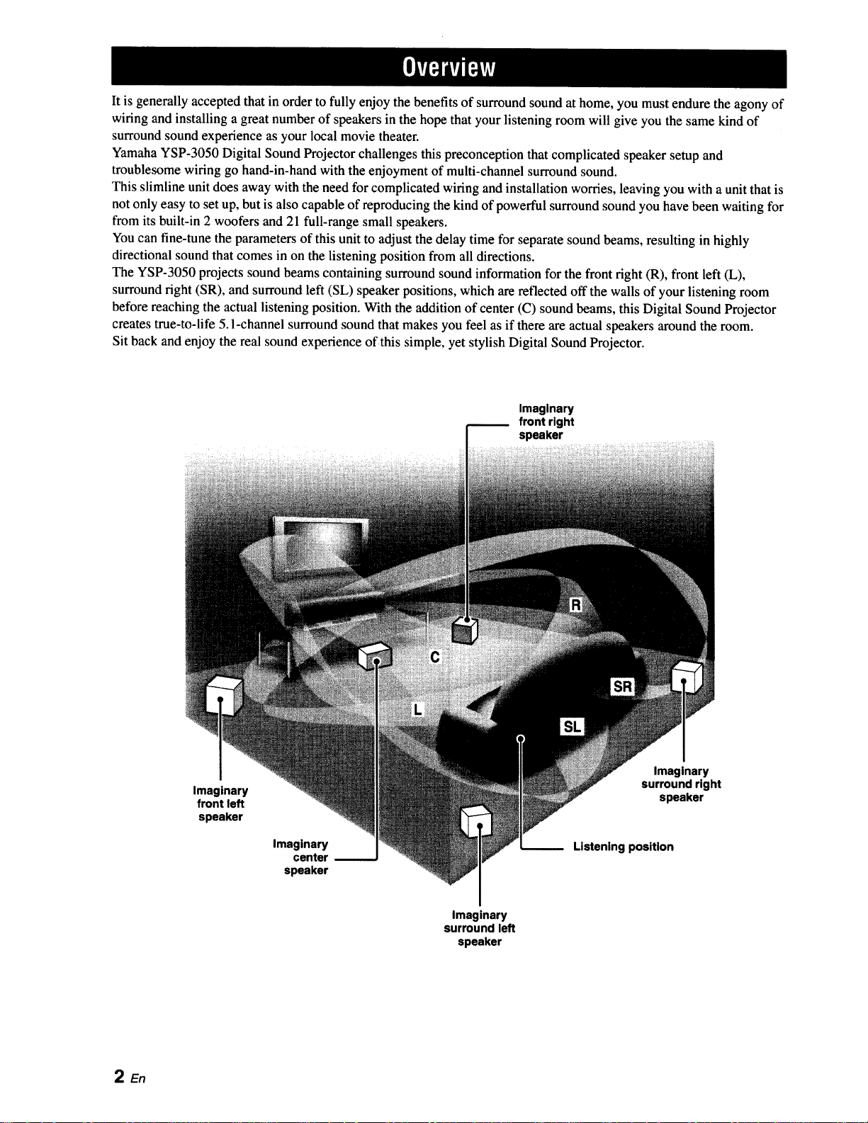
It is generally accepted that in orderto fully enjoy the benefits of surround sound at home, you must endure the agony of
wiring and installing a great number of speakers in the hope that your listening room will give you the same kind of
surround sound experience as your local movie theater.
Yamaha YSP-3050 Digital Sound Projector challenges this preconception that complicated speaker setup and
troublesome wiring go hand-in-hand with the enjoyment of multi-channel surround sound.
This slimline unit does away with the need for complicated wiring and installation worries, leaving you with a unit that is
not only easy to set up, but is also capable of reproducing the kind of powerful surround sound you have been waiting for
from its built-in 2 woofers and 21 full-range small speakers.
You can fine-tune the parameters of this unit to adjust the delay time for separate sound beams, resulting in highly
directional sound that comes in on the listening position from all directions.
The YSP-3050 projects sound beams containing surround sound information for the front right (R), front left (L),
surround right (SR), and surround left (SL) speaker positions, which are reflected off the walls of your listening room
before reaching the actual listening position. With the addition of center (C) sound beams, this Digital Sound Projector
creates true-to-life 5.1-channel surround sound that makes you feel as if there are actual speakers around the room.
Sit back and enjoy the real sound experience of this simple, yet stylish Digital Sound Projector.
Imaginary
front right
speaker
2En
Imaginary
front left
speaker
Imaginary
center
speaker
Imaginary
surround right
speaker
Listening position
Imaginary
surround left
speaker
DigitalSoundProjectorTM
The Digital Sound Projector technology allows one slim
unit to control and steer multiple channels of sound to
generate multi-channel surround sound, thus eliminates
the need for satellite loudspeakers and cabling normally
associated with conventional surround sound systems.
This unit also employs the beam modes that let you enjoy
the surround sound (5 Beam, Stereo plus 3 Beam and 3
Beam), 2-channel and 5-channel stereo playback, and My
Beam.
My Surround
In addition to the above mentioned beam modes, this unit
is equipped with My Surround beam mode that allows you
to enjoy surround system even in a small listening area.
My Surround is a function integrated and optimized with
DiMAGIC's Euphony technology and Yamaha's Beam
reproduction system.
My Beam
This unit employs My Beam that ensures a clear sound in
a noisy environment. You can adjust the beam angle
manually or automatically.
Cinema DSP
This unit employs the Cinema DSP technology developed
by Yamaha Corporation that lets you experience movies at
home with all the original dramatic sound impact.
HDMI TM (High-Definition Multimedia Interface)
• HDMI interface for standard, enhanced, or high-definition
video (including 1080p video signal transmission) as well as
multi-channel digital audio based on HDCP
• Simple and easy connections with HDMI supported external
components
• Functional link with an HDMI control-compatible TV
• Analog video up-scaling from 480i (NTSC)/576i (PAL) or
480p (NTSC)/576p (PAL) to 720p or 1080i
Versatile Remote Control
The supplied remote control comes with preset remote
control codes used to control the DVD player, VCR, cable
TV tuner, and digital satellite tuner connected to this unit.
In addition, the remote control is equipped with the macro
capability that enables a series of operations with the press
of a single button.
AUTO SETUP (IntelliBeam)
This unit employs the automatic sound beam and acoustic
optimization technology with the aid of the supplied
IntelliBeam microphone. You can avoid troublesome
listening-based speaker setup and achieve highly accurate
sound beam adjustments that best match your listening
environment.
Compatibility with the Newest Technologies
This unit employs decoders compatible with Dolby
Digital, DTS, Dolby Pro Logic, Dolby Pro Logic II, DTS
Neo:6, Music Enhancer, and Neural Surround.
• Dolby Digital
This is the standard audio signal format used on various
digital media such as DVD, Blu-ray, and HD DVD. This
surround technology delivers high-quality digital audio for up
to 5.1 discrete channels to produce a directional and more
realistic effect.
• DTS
This is the standard audio signal format used on various
digital media such as DVD, Blu-ray, and HD DVD. This
surround technology delivers high-quality digital audio for up
to 5. l discrete channels to produce a directional and more
realistic effect.
• Dolby Pro Logic
A surround system that takes a 4-channel signal and records it
as a 2-channel signal, then by way of some arithmetic
processing converts back to an independent 4-channel signal
for playback.
• Dolby Pro Logic II
Dolby Pro Logic II is an improved technique used to decode
vast numbers of existing Dolby Surround software.
This new technology enables a discrete 5-channel playback
with 2 front left and right channels, 1 center channel, and 2
surround left and right channels (instead of only 1 surround
channel for conventional Pro Logic technology).
• DTS Neo:6
This technology decodes the conventional 2-channel sources
for 6-channel playback, enabling playback with the full-range
channels with higher separation. Music mode and Cinema
mode are available to play back music and movie sources
respectively.
• Music Enhancer to restore the original depth and width of
compression artifacts such as the MP3 format.
• Neural Surround decoder.
Sophisticated FM tuner
• 40-station random and direct preset tuning
• Automatic preset tuning
XM TM Satellite Radio
• XM Satellite Radio tuning capability (using the XM Mini-
Tuner Dock, and Antenna sold separately by XM Satellite
Radio)
• Neural Surround decoder to play back the XM HD content of
XM Satellite Radio broadcasts in multi-channels, resulting in
a full surround sound experience
• XM Satellite Radio information displaying capability
iPod TM Controlling Capability
• DOCK terminal to connect a Yamaha iPod universal dock
(such as the YDS-10, sold separately), which supports iPod
(Click and Wheel), iPod nano, and iPod mini
• Playback information displaying capability
• Battery charging capability
3 En
Ilr*-,lll_
inte\l/Beam
The "tntelUBeam" logo and "IntelliBeam" are trademarks of
Yamaha Corporation.
The "_" logo and "Cinema DSP" are registered
trademarks of Yamaha Corporation.
®
Manufactured under license from 1 Ltd. Worldwide patents
applied for.
The "_" logo and "Digital Sound Projector 1_'''are trademarks
of 1Ltd.
DIGITAL
Manufactured under license from Dolby Laboratories.
"Dolby", "Pro Logic", and the double-D symbol are trademarks
of Dolby Laboratories.
Odlti
DigitalSu_und [Neo:6"
"DTS" and "Neo:6" are registered trademarks of DTS, Inc.
H
"HDMI", the "HDMI" logo and "High-Definition Multimedia
Interface" are trademarks or registered trademarks of HDMI
Licensing LLC.
TruBass, SRS and the "(0) "symbol are registered trademarks
of SRS Labs, Inc. TruBass technology is incorporated under
license from SRS Labs, Inc.
/_ EUPHONY
EUPHONY TM is a trademark of DiMAGIC Co., Ltd.
iPodTM
"iPod" is a trademark of Apple Inc., registered in the U.S. and
other countries.
))).,XMDM JOWMini.Tun r
The XM name and related logos are registered trademarks of XM
Satellite Radio Inc.
neural
8URROUNCI.
Neural Surround TM name and related logos are trademarks owned
by Neural Audio Corporation.
4 En
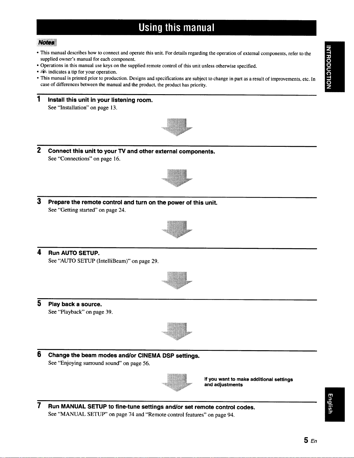
• This manual describes how to connect and operate this unit. For details regarding the operation of external components, refer to the
supplied owner's manual for each component.
• Operations in this manual use keys on the supplied remote control of this unit unless otherwise specified.
• --',i,':indicates a tip for your operation.
• This manual is printed prior to production. Designs and specifications are subject to change in part as a result of improvements, etc. In
case of differences between the manual and the product, the product has priority.
1 Install this unit in your listening room.
See "Installation" on page 13.
2 Connect this unit to your TV and other external components.
See "Connections" on page 16.
3 Prepare the remote control and turn on the power of this unit.
See "Getting started" on page 24.
4 Run AUTO SETUP.
See "AUTO SETUP (IntelliBeam)" on page 29.
5 Play back a source.
See "Playback" on page 39.
6
Change the beam modes and/or CINEMA DSP settings.
See "Enjoying surround sound" on page 56.
If you want to make additional settings
and adjustments
7 Run MANUAL SETUP to fine-tune settings and/or set remote control codes.
See "MANUAL SETUP" on page 74 and "Remote control features" on page 94.
SEn
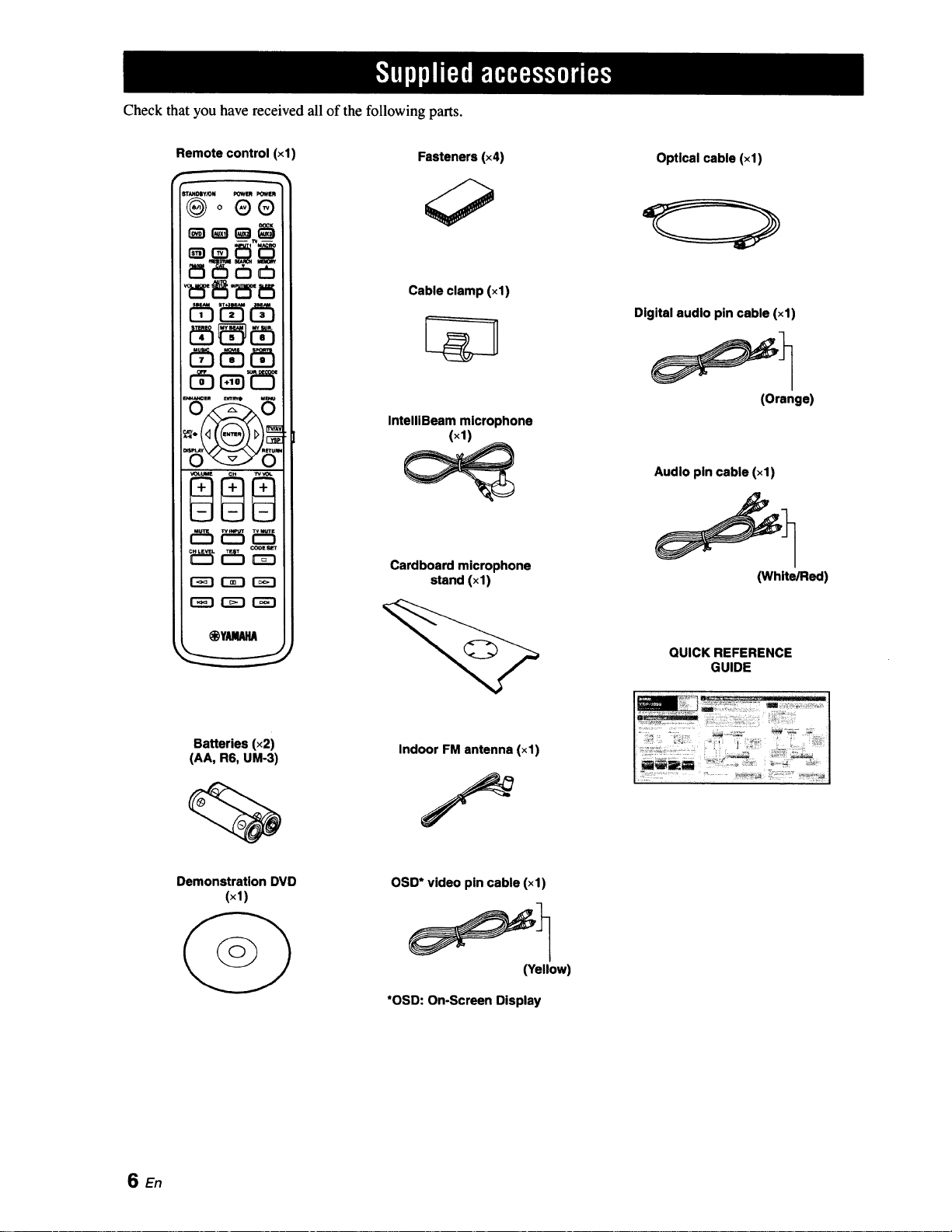
Check that you have received all of the following parts.
Remote control (xl)
®o®®
_ _5 cb_
r-_-i r-z-i r"_-i
Fasteners (×4)
Cable clamp (×1)
IntelllBeam microphone
(×1)
Cardboard microphone
stand (xl)
Optical cable (×1)
Digital audio pin cable (×1)
(Orange)
Audio pin cable (xl)
(White/Red)
Batteries (x2)
(AA, R6, UM-3)
Demonstration DVD
(×1)
QUICK REFERENCE
GUIDE
Indoor FM antenna (×1)
OSD* video pin cable (xl)
(Yellow)
*OSD: On-Screen Display
SEn
INPUT
VOLUME ÷ STANDBY/ON
1
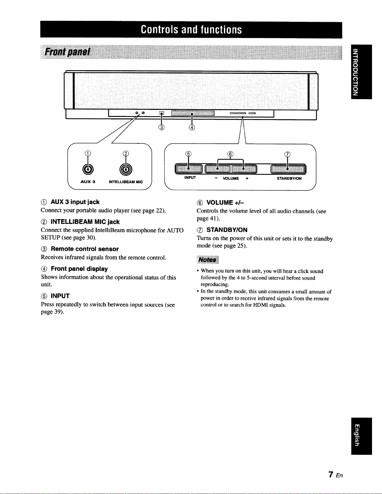
0) AUX 3 input jack
Connect your portable audio player (see page 22).
(_ INTELLIBEAM MIC jack
Connect the supplied IntelliBeam microphone for AUTO
SETUP (see page 30).
(_ Remote control sensor
Receives infrared signals from the remote control.
(_ Front panel display
Shows information about the operational status of this
unit.
INPUT
Press repeatedly to switch between input sources (see
page 39).
_) VOLUME +/-
Controls the volume level of all audio channels (see
page 41).
O STAN DBYION
Turns on the power of this unit or sets it to the standby
mode (see page 25).
• When you turn on this unit, you will hear a click sound
followed by the 4 to 5-second interval before sound
reproducing.
• In the standby mode, this unit consumes a small amount of
power in order to receive infrared signals from the remote
control or to search for HDMI signals.
TEn
Ilwml_'TJ'Tll|°||'|f|Pif|ql(,
IIIU uln ;'Ill "-';U
IIIII IIIII lllll IIIII
lull IllU llUl ,,,U
/ill| .... , .....ll;ll uu| eenn
III
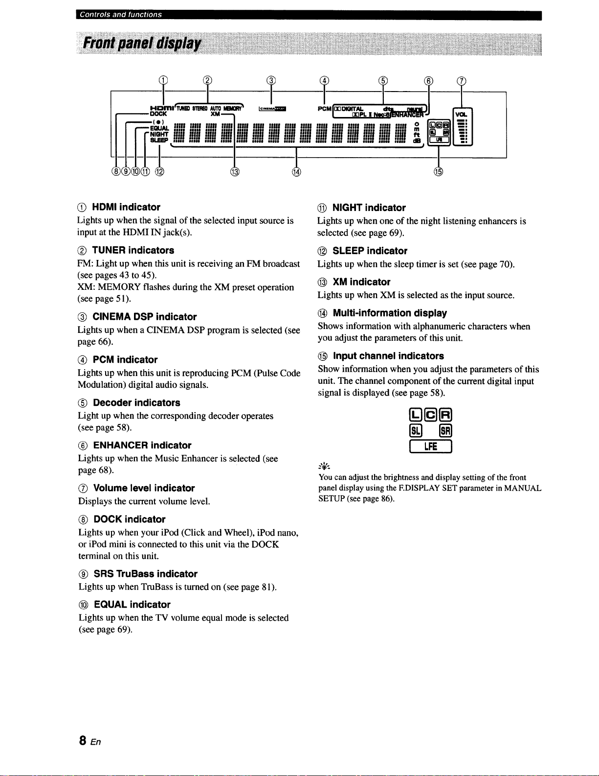
O HDMI indicator
Lights up when the signal of the selected input source is
input at the HDMI IN jack(s).
Q TUNER indicators
FM: Light up when this unit is receiving an FM broadcast
(see pages 43 to 45).
XM: MEMORY flashes during the XM preset operation
(see page 51).
CINEMA DSP indicator
Lights up when a CINEMA DSP program is selected (see
page 66).
Q PCM indicator
Lights up when this unit is reproducing PCM (Pulse Code
Modulation) digital audio signals.
(_) Decoder indicators
Light up when the corresponding decoder operates
(see page 58).
(_) ENHANCER indicator
Lights up when the Music Enhancer is selected (see
page 68).
O Volume level indicator
Displays the current volume level.
NIGHT indicator
Lights up when one of the night listening enhancers is
selected (see page 69).
(_) SLEEP indicator
Lights up when the sleep timer is set (see page 70).
(_ XM indicator
Lights up when XM is selected as the input source.
(_ Multi-information display
Shows information with alphanumeric characters when
you adjust the parameters of this unit.
O Input channel indicators
Show information when you adjust the parameters of this
unit. The channel component of the current digital input
signal is displayed (see page 58).
[][][]
! LFEI
You can adjust the brightness and display setting of the front
panel display using the F.DISPLAY SET parameter in MANUAL
SETUP (see page 86).
_) DOCK indicator
Lights up when your iPod (Click and Wheel), iPod nano,
or iPod mini is connected to this unit via the DOCK
terminal on this unit.
_) SRS TruBass indicator
Lights up when TruBass is turned on (see page 81).
EQUAL indicator
Lights up when the TV volume equal mode is selected
(see page 69).
SEn

q_r_kla.llll*Jl#lJINelol#t_
(i) ANTENNA jack
Connect the FM antenna (see page 23).
(_) DOCK terminal
Connect the Yamaha iPod universal dock (such as YDS-
10, sold separately) (see page 53).
(_) AUX 1 AUDIO INPUT jacks
Connect an external component via an analog connection
(see page 20).
(_) TV/STB AUDIO INPUT jacks
Connect your TV, digital satellite tuner, or cable TV tuner
via an analog connection (see pages 21).
(_) VIDEO OUT jack
Connect to the video input jack of your TV via a
composite analog video connection to display the OSD of
this unit (see page 21).
® SUBWOOFER OUT jack
Connect your subwoofer (see page 22).
O STB VIDEO INPUT jacks
Connect a digital satellite tuner or a cable TV tuner via a
composite analog video connection (see pages 19).
® DVD COMPONENT VIDEO INPUT jacks
Connect aDVD player/recorder or anexternalcomponent
via acomponentanalogvideoconnection(seepages 19
and 20).
(_) AUX 2 COAXIAL DIGITAL INPUT jack
Connect an external component via a coaxial digital
connection(seepage20).
AUX 1 OPTICAL DIGITAL INPUT jack
Connect an external component via an optical digital
connection (see page 20).
Q TV/STB OPTICAL DIGITAL INPUT jack
Connect your TV, digital satellite tuner, or cable TV tuner
via an optical digital connection (see pages 19 and 21).
DVD COAXIAL DIGITAL INPUT jack
Connect your DVD player via a coaxial digital connection
(see page 19).
(_ XM antenna jack
Connect your XM Mini-Tuner Home Dock (sold
separately) (see page 47).
(_) IR INterminal
This is a control expansion terminal for commercial use
only (see page 23).
STB HDMI IN jack
Connect your digital satellite tuner, cable TV tuner, digital
airwave tuner, or game console via an HDMI connection
(see page 18).
DVD HDMI IN jack
Connect your DVD player via an HDMI connection (see
page 18).
HDMI OUT jack
Connect to the HDMI input jack on your HDMI
component such as a TV or a projector connected to this
unit (see page 18 to 20).
(_ AC power supply cable
Connect to the AC wall outlet (see page 23).
9 En
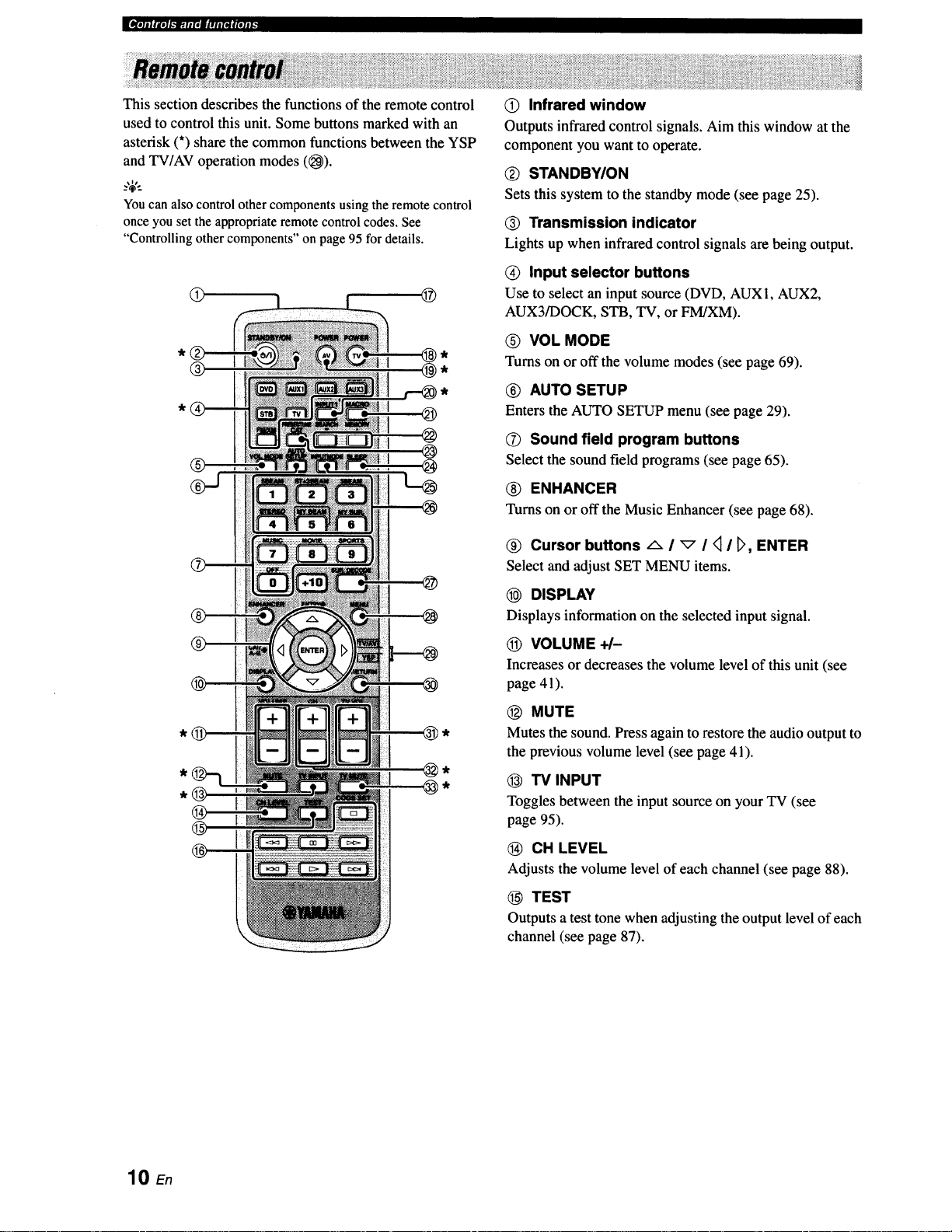
This section describes the functions of the remote control
used to control this unit. Some buttons marked with an
asterisk (*) share the common functions between the YSP
and TV/AV operation modes ((_).
_%'..
You can also control other components using the remote control
once you set the appropriate remote control codes. See
"Controlling other components" on page 95 for details.
@ @
® @,
@ Infrared window
Outputs infrared control signals. Aim this window at the
component you want to operate.
Q STANDBY/ON
Sets this system to the standby mode (see page 25).
@ Transmission indicator
Lights up when infrared control signals are being output.
(_) Input selector buttons
Use to select an input source (DVD, AUX1, AUX2,
AUX3/DOCK, STB, TV, or FM/XM).
O VOL MODE
Turns on or off the volume modes (see page 69).
® AUTO SETUP
Enters the AUTO SETUP menu (see page 29).
®
@
(_ Sound field program buttons
Select the sound field programs (see page 65).
(_) ENHANCER
Turns on or off the Music Enhancer (see page 68).
@ Cursor buttons -_- I _ I _ I D, ENTER
Select and adjust SET MENU items.
@ DISPLAY
Displays information on the selected input signal.
(_) VOLUME +/-
Increasesor decreases the volume level of this unit (see
page 41).
@ MUTE
Mutes the sound. Press again to restore the audio output to
the previous volume level (see page 41).
@ TV INPUT
Toggles between the input source on your TV (see
page 95).
CH LEVEL
Adjusts the volume level of each channel (see page 88).
10 En
TEST
Outputs a test tone when adjusting the output level of each
channel (see page 87).
,,llIIIIJ'e]l._]p;.llit||lll(ll|le]ll_
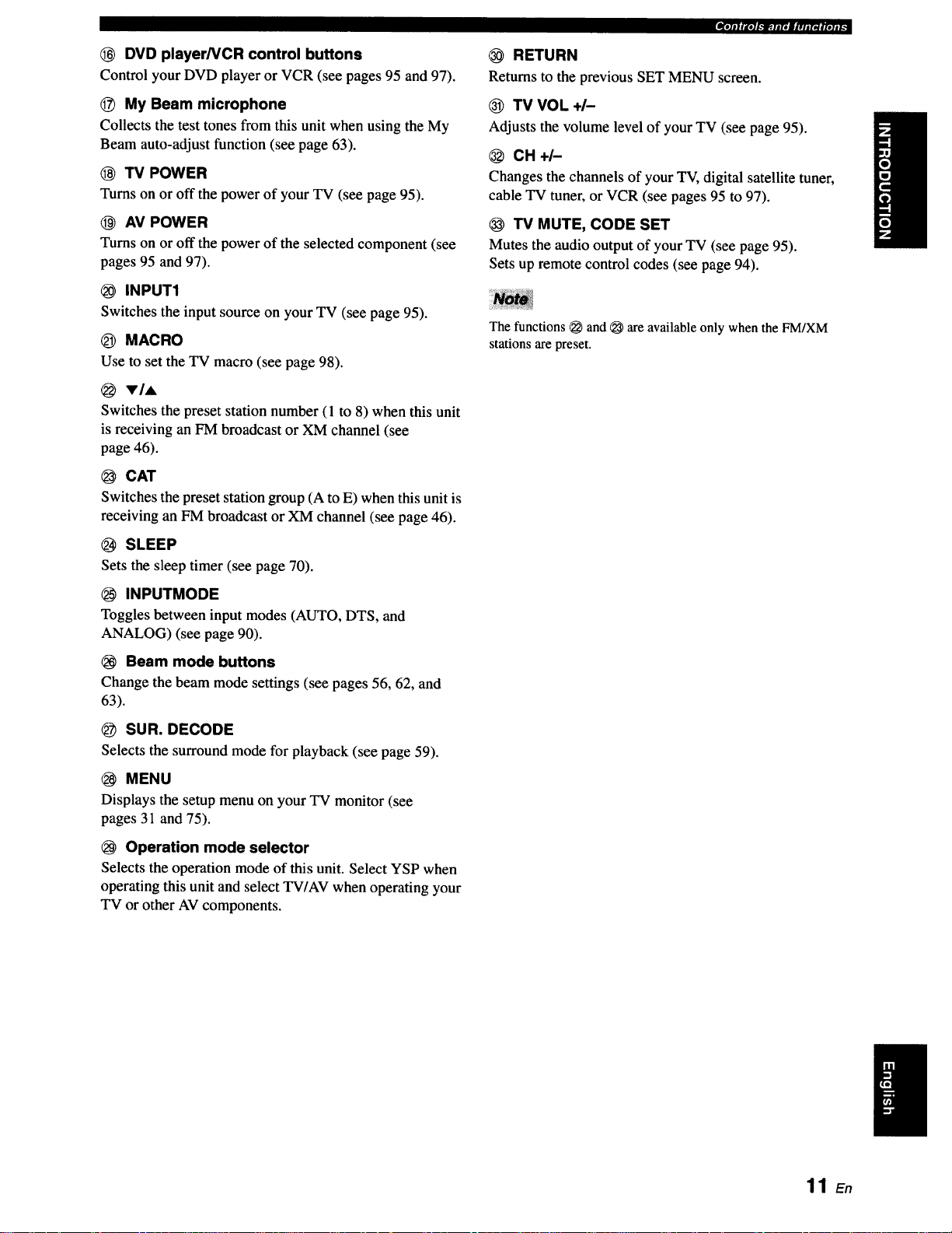
DVD player/VCR control buttons
Control your DVD player or VCR (see pages 95 and 97).
_) My Beam microphone
Collects the test tones from this unit when using the My
Beam auto-adjust function (see page 63).
(_ TV POWER
Turns on or off the power of your TV (see page 95).
AV POWER
Turns on or off the power of the selected component (see
pages 95 and 97).
INPUT1
Switches the input source on your TV (see page 95).
_) MACRO
Use to set the TV macro (see page 98).
VIA
Switches the preset station number (1 to 8) when this unit
is receiving an FM broadcast or XM channel (see
page 46).
@ CAT
Switches the preset station group (A to E) when this unit is
receiving an FM broadcast or XM channel (see page 46).
SLEEP
Sets the sleep timer (see page 70).
RETURN
Returns to the previous SET MENU screen.
TV VOL+/-
Adjusts the volume level of your TV (see page 95).
CH+I-
Changes the channels of your TV, digital satellite tuner,
cable TV tuner, or VCR (see pages 95 to 97).
TV MUTE, CODE SET
Mutes the audio output of your TV (see page 95).
Sets up remote control codes (see page 94).
The functions _ and _ are available only when the FM/XM
stations are preset.
INPUTMODE
Toggles between input modes (AUTO, DTS, and
ANALOG) (see page 90).
Beam mode buttons
Change the beam mode settings (see pages 56, 62, and
63).
SUR. DECODE
Selects the surround mode for playback (see page 59).
MENU
Displays the setup menu on your TV monitor (see
pages 31 and 75).
Operation mode selector
Selects the operation mode of this unit. Select YSP when
operating this unit and select TV/AV when operating your
TV or other AV components.
11 En
E_r;11_I.'_.fip_-Iaqf|qlt'
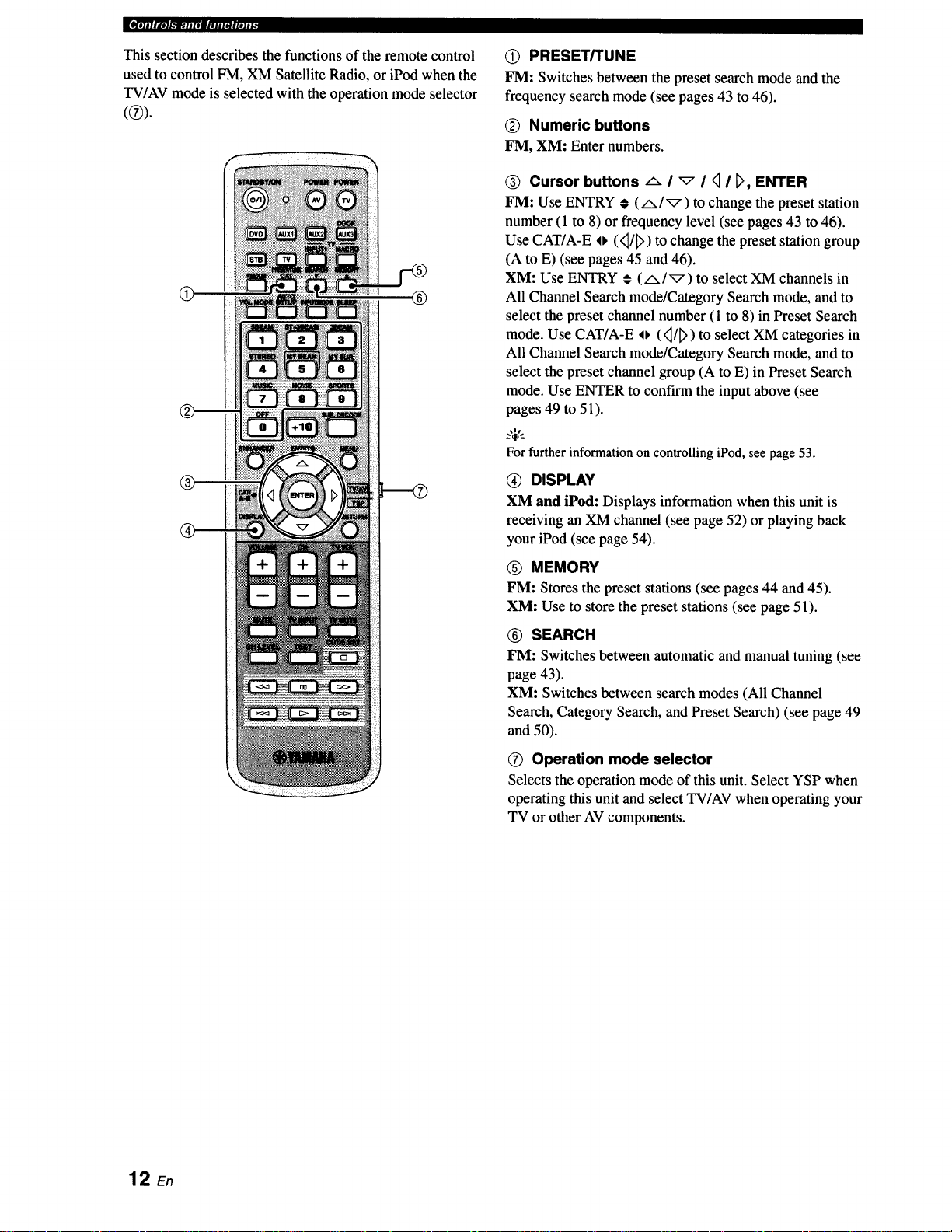
This section describes the functions of the remote control
used to control FM, XM Satellite Radio, or iPod when the
TV/AV mode is selected with the operation mode selector
®
®
Q PRESET/TUNE
FM: Switches between the preset search mode and the
frequency search mode (see pages 43 to 46).
(_ Numeric buttons
FM, XM: Enter numbers.
® Cursor buttons _ I _ I _ I _, ENTER
FM: Use ENTRY # (/x/_) to change the preset station
number (1 to 8) or frequency level (see pages 43 to 46).
Use CAT/A-E o (<_/_>)to change the preset station group
(A to E) (see pages 45 and 46).
XM: Use ENTRY € (A/_) to select XM channels in
All Channel Search mode/Category Search mode, and to
select the preset channel number (1 to 8) in Preset Search
mode. Use CAT/A-E o (<_/_>)to select XM categories in
All Channel Search mode/Category Search mode, and to
select the preset channel group (A to E) in Preset Search
mode. Use ENTER to confirm the input above (see
pages 49 to 51).
:,;€.
For further information on controlling iPod, see page 53.
@ DISPLAY
XM and iPod: Displays information when this unit is
receiving an XM channel (see page 52) or playing back
your iPod (see page 54).
(_) MEMORY
FM: Stores the preset stations (see pages 44 and 45).
XM: Use to store the preset stations (see page 51).
® SEARCH
FM: Switches between automatic and manual tuning (see
page 43).
XM: Switches between search modes (All Channel
Search, Category Search, and Preset Search) (see page 49
and 50).
O Operation mode selector
Selects the operation mode of this unit. Select YSP when
operating this unit and select TV/AV when operating your
TV or other AV components.
12 En
This section describes a suitable installation location to install this unit using a metal wall bracket, a rack or a stand.
Depending on your installation environment, connections with external components can be done before installing this
unit. We recommend that you temporarily place and arrange all components, including this unit, in order to decide which
procedure should come first. Especially when you make a connection over HDMI, we recommend that you make a
connection first before installation (see page 18).
This unit creates surround sound by reflecting projected
sound beams off the walls of your listening room. The
surround sound effects produced by this unit may not be
sufficient when this unit is installed in the following
locations.
• Rooms with walls inadequate for reflecting sound
beams
• Rooms with acoustically absorbent walls
• Rooms with measurements outside the following
range: W (3 to 7 m (10 to 23 ft)) x H (2 to 3.5 m (7 to
11.5 ft)) x D (3 to 7 m (10 to 23 ft))
• Rooms with less than 1.8 m (6 ft) from the listening
position to this unit
• Rooms where objects such as furniture are likely to
obstruct the path of sound beams
• Rooms where the listening position is close to the walls
• Rooms where the listening position is not in front of
this unit
• You can enjoy surround sound by selecting My Surround (see
page 57) as the beam mode even if your listening room may not
fulfill the above conditions (except when the listening position
is not directly facing toward the front of this unit).
• You can also enjoy surround sound by selecting 2-channel or 5-
channel stereo playback (see page 62) or My Beam (see
page 63) as the beam mode even if your listening room may not
fulfill the above conditions.
• We do not recommend putting this unit directly on the floor of
your listening room. Please install this unit using a metal wall
bracket, a rack, or a stand.
• This unit weighs 11.5 kg (25 lbs 6 oz). Be sure to install this
unit where it will not fall subject to vibrations, such as from an
earthquake, and where it is out of the reach of children.
• When using a cathode-ray tube (CRT) TV, do not install this
unit directly above your TV.
• This unit is shielded against magnetic rays. However, if the
picture on your TV screen becomes blurred or distorted, we
recommend moving this unit away from your TV.
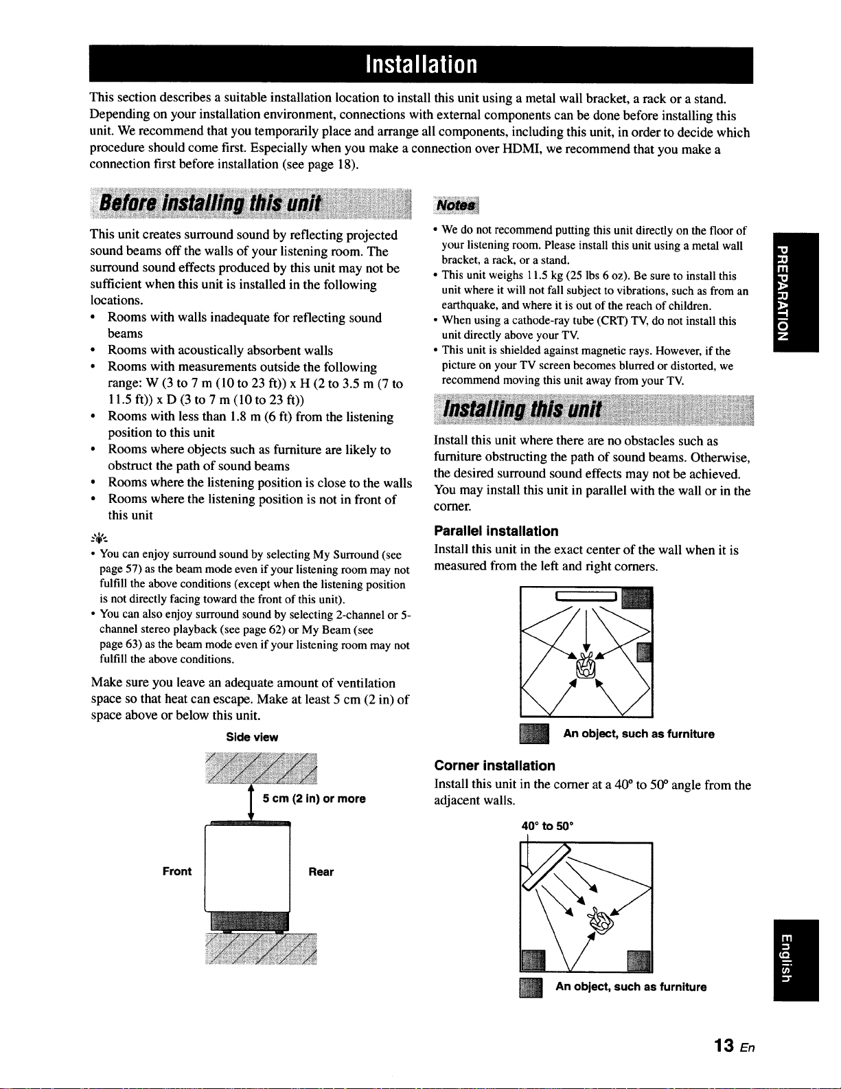
Install this unit where there are no obstacles such as
furniture obstructing the path of sound beams. Otherwise,
the desired surround sound effects may not be achieved.
You may install this unit in parallel with the wall or in the
corner.
Parallel installation
Install this unit in the exact center of the wall when it is
measured from the left and right corners.
Make sure you leave an adequate amount of ventilation
space so that heat can escape. Make at least 5 cm (2 in) of
space above or below this unit.
Side view
5 cm (2 in) or more
Front Rear
l
Corner installation
Install this unit in the corner at a 40 °to 50° angle from the
adjacent walls.
40° to 50°
m
An object, such as furniture
An object, such as furniture
13 En
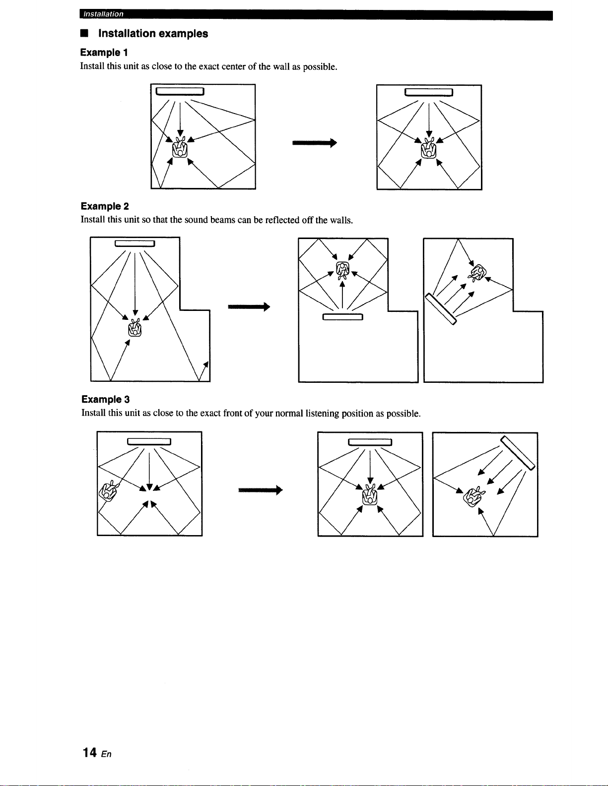
• Installation examples
Example 1
Install this unit as close to the exact center of the wall as possible.
[ I
Example 2
Install this unit so that the sound beams can be reflected off the walls.
I !
/
/\
I !
I
I I
I
Example 3
Install this unit as close to the exact front of your normal listening position as possible.
! I
I
14_
r_lffll_fpjj
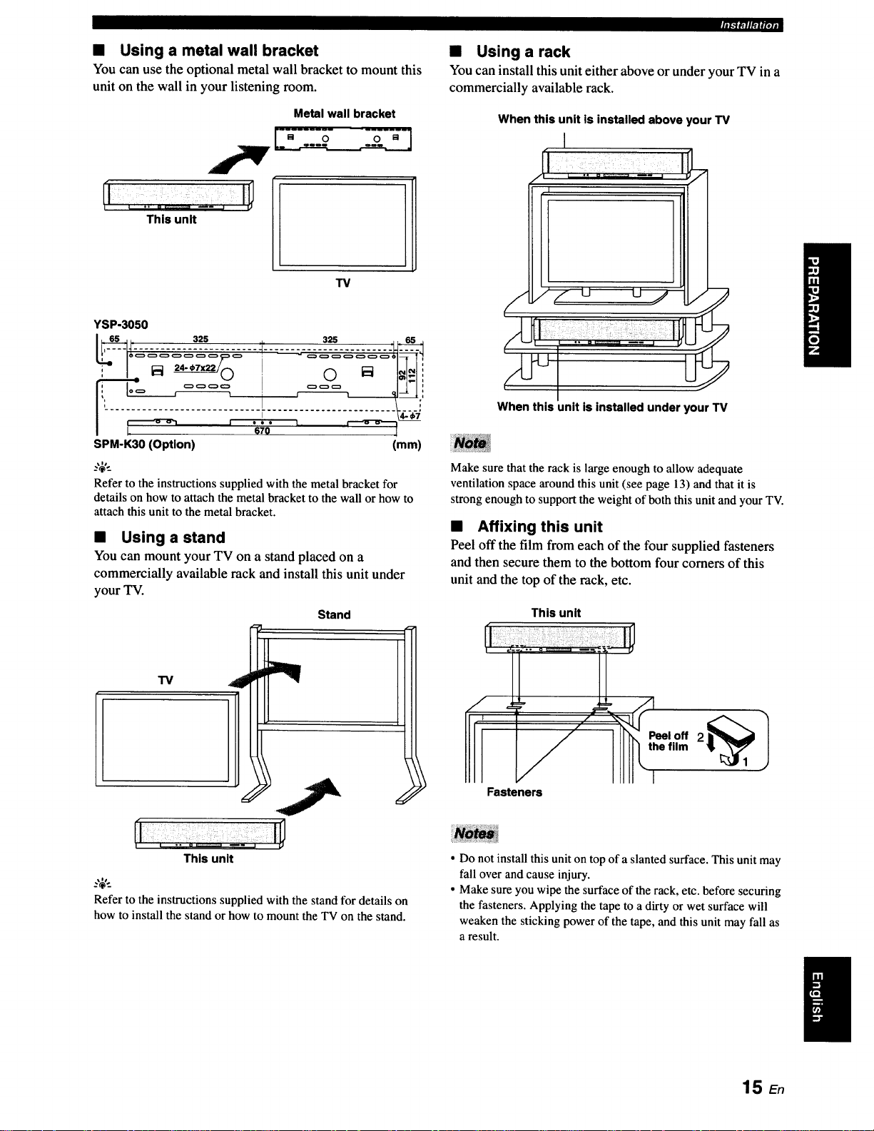
• Using a metal wall bracket
You can use the optional metal wall bracket to mount this
unit on the wall in your listening room.
Metal wall bracket
This unit
TV
YSP-3050
SPM-K30 (Option) (mm)
_%'._
Refer to the instructions supplied with the metal bracket for
details on how to attach the metal bracket to the wall or how to
attach this unit to the metal bracket.
• Using a stand
You can mount your TV on a stand placed on a
commercially available rack and install this unit under
your TV.
Stand
• Using a rack
You can install this unit either above or under your TV in a
commercially available rack.
When this unit is installed above your TV
I
When this unit is installed under your TV
Make sure that the rack is large enough to allow adequate
ventilation space around this unit (see page 13) and that it is
strong enough to support the weight of both this unit and your TV.
• Affixing this unit
Peel off the film from each of the four supplied fasteners
and then secure them to the bottom four comers of this
unit and the top of the rack, etc.
This unit
"13/
i
This unit
..,;,..
Refer to the instructions supplied with the stand for details on
how to install the stand or how to mount the TV on the stand.
Fasteners
• Do not install this unit on top of a slanted surface. This unit may
fall over and cause injury.
• Make sure you wipe the surface of the rack, etc. before securing
the fasteners. Applying the tape to a dirty or wet surface will
weaken the sticking power of the tape, and this unit may fall as
a result.
15 En
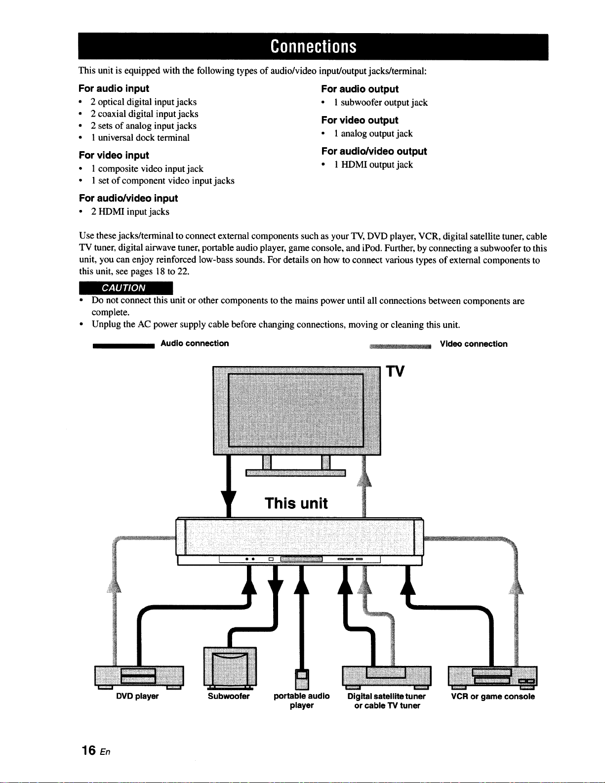
This unit is equipped with the following types of audio/video input/output jacks/terminal:
For audio input
• 2 optical digital input jacks
• 2 coaxial digital input jacks
• 2 sets of analog input jacks
• 1 universal dock terminal
For video input
• 1composite video input jack
For audio output
• 1 subwoofer output jack
For video output
• 1 analog output jack
For audio/video output
• 1HDMIoutputjack
• 1set of component video input jacks
For audio/video input
• 2 HDMI input jacks
Use these jacks/terminal to connect external components such as your TV, DVD player, VCR, digital satellite tuner, cable
TV tuner, digital airwave tuner, portable audio player, game console, and iPod. Further, by connecting a subwoofer to this
unit, you can enjoy reinforced low-bass sounds. For details on how to connect various types of external components to
this unit, see pages 18 to 22.
r_
• Do not connect this unit or other components to the mains power until all connections between components are
complete.
• Unplug the AC power supply cable before changing connections, moving or cleaning this unit.
Audio connection
_. - _-L.... : _ Video connection
TV
16 En
This unit
• • rt
DVD player Subwoofer portable audio
player
Digital satellite tuner
or cable TV tuner
VCR or game console
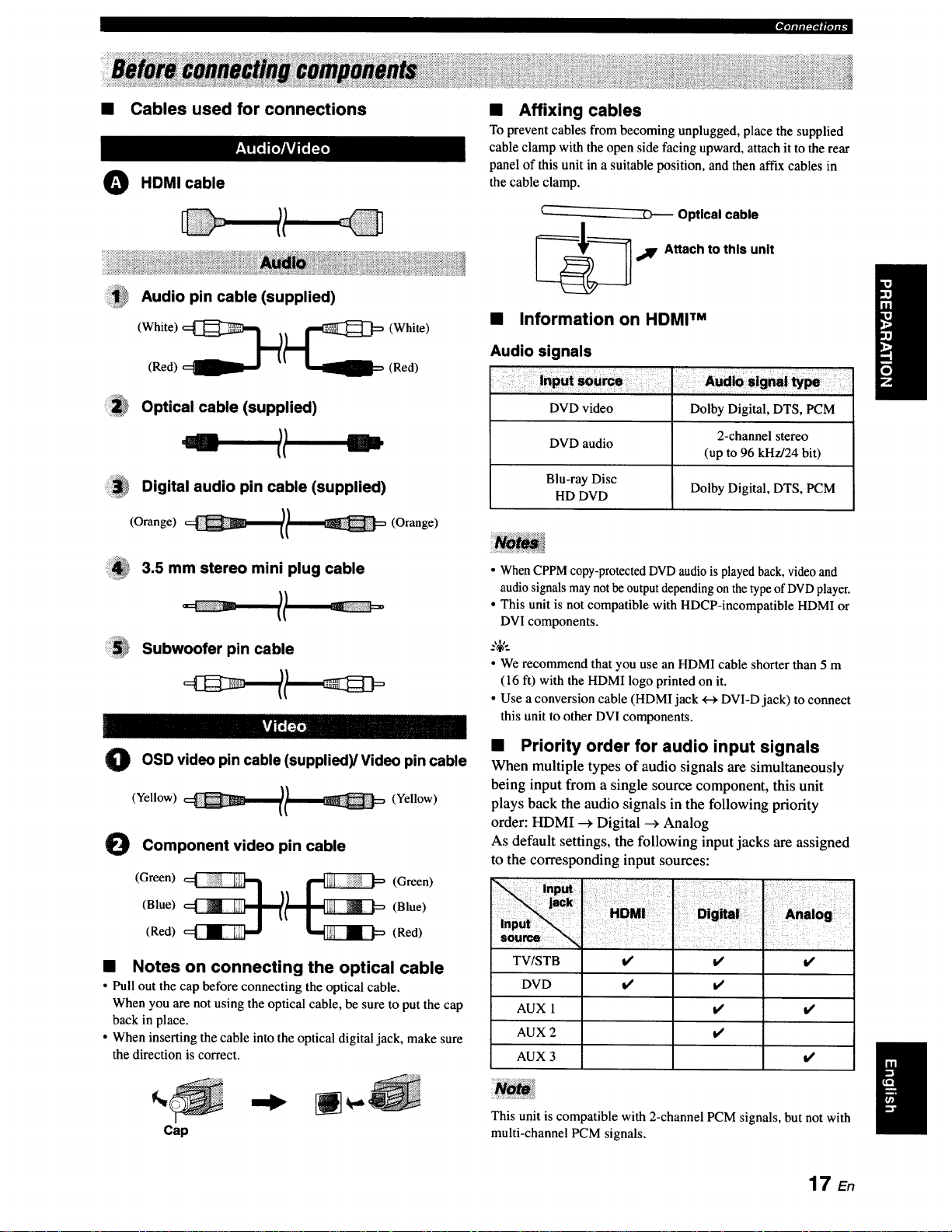
• Cables used for connections
O HDMI cable
Audio pin cable (supplied)
(Red) (Red)
• Affixing cables
To prevent cables from becoming unplugged, place the supplied
cable clamp with the open side facing upward, attach it to the rear
panel of this unit in a suitable position, and then affix cables in
the cable clamp.
Optical cable
,_IF Attach to this unit
• Information on HDMI TM
Audio signals
Optical cable (supplied)
Digital audio pin cable (supplied)
(Orange) l/ (Orange)
3.5 mm stereo mini plug cable
Subwoofer pin cable
OSD video
O pin (supplied)/Video pin cable
(Yellow) (Yellow)
Component video pin cable
cable
DVD video Dolby Digital, DTS, PCM
DVD audio
Blu-ray Disc
HD DVD Dolby Digital, DTS, PCM
• When CPPM copy-protected DVDaudio is played back, video and
audio signals may notbe output depending on the type of DVDplayer.
• This unit is not compatible with HDCP-incompatible HDMI or
DVI components.
.%,..
• We recommend that you use an HDMI cable shorter than 5 m
(16 ft) with the HDMI logo printed on it.
• Use a conversion cable (HDMI jack +-_DVI-D jack) to connect
this unit to other DVI components.
2-channel stereo
(up to 96 kHz/24 bit)
• Priority order for audio input signals
When multiple types of audio signals are simultaneously
being input from a single source component, this unit
plays back the audio signals in the following priority
order: HDMI _ Digital --_Analog
As default settings, the following input jacks are assigned
to the corresponding input sources:
(Blue) (Blue)
(Green) __ (Green)
(Red) (Red)
• Notes on connecting the optical cable
• Pull out the cap before connecting the optical cable.
When you are not using the optical cable, be sure to put the cap
back in place.
• When inserting the cable into the optical digital jack, make sure
the direction is correct.
Cap
TVISTB
DVD
AUX 1
AUX 2
AUX 3
This unit is compatible with 2-channel PCM signals, but not with
multi-channel PCM signals.
i/ t/
t/ t/
t/
it
t,t
l/
t/
17 E,
_[D[olili['..IOll[elig
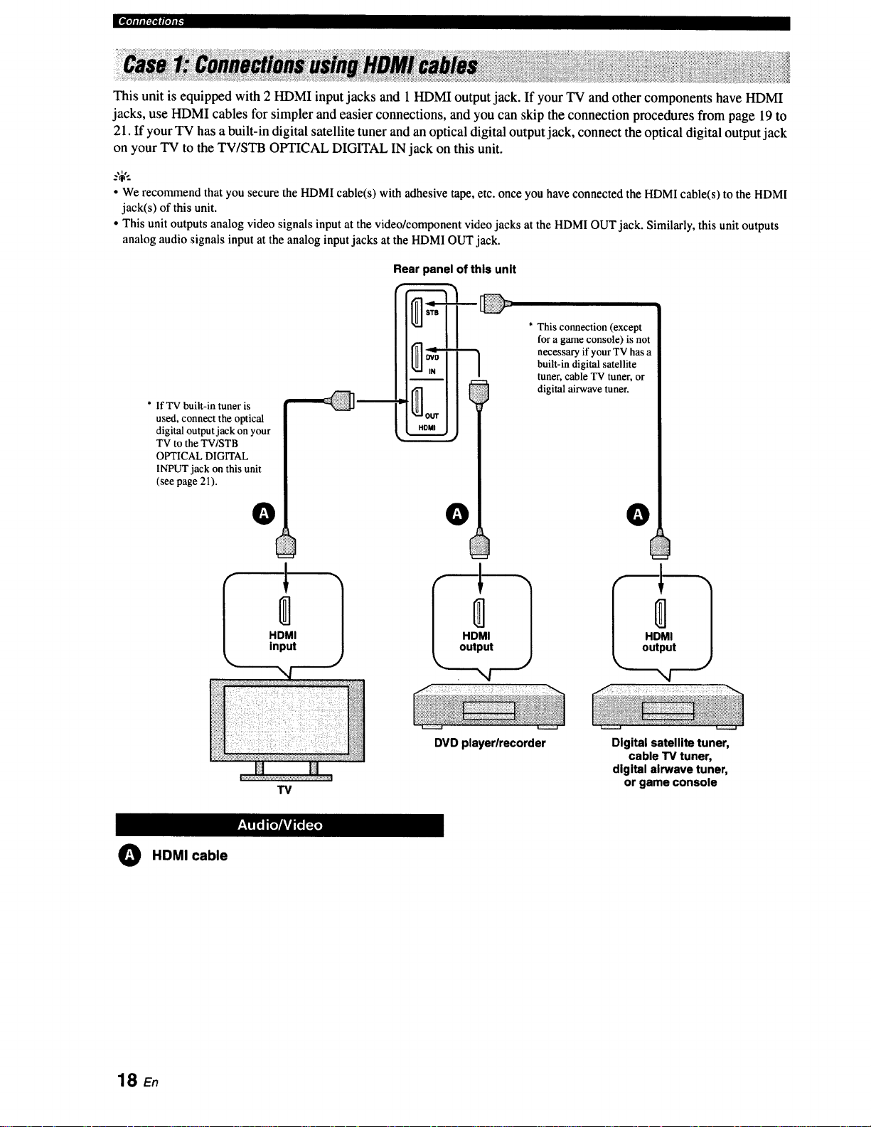
This unit is equipped with 2 HDMI input jacks and 1 HDMI output jack. If your TV and other components have HDMI
jacks, use HDMI cables for simpler and easier connections, and you can skip the connection procedures from page 19 to
21. If your TV has a built-in digital satellite tuner and an optical digital output jack, connect the optical digital output jack
on your TV to the TV/STB OPTICAL DIGITAL IN jack on this unit.
• We recommendthat you securethe HDMIcable(s)with adhesive tape,etc. onceyou have connectedthe HDMI cable(s)tothe HDMI
jack(s) of thisunit.
• Thisunit outputs analog video signalsinput at the video/componentvideo jacks at the HDMI OUTjack. Similarly,this unit outputs
analogaudio signals input at the analog inputjacks at the HDMIOUT jack.
Rear panel of this unit
* This connection (except
for a game console) is not
necessary if your TV has a
built-in digital satellite
tuner, cable TV tuner, or
digital airwave tuner.
* IfTV built-in tuner is
used, connect the optical
digital output jack on your
TV to the TV/STB
OPTICAL DIGITAL
INPLrr jack on this unit
(see page 21).
O HDMI cable
O
HDMI
input
TV
0
HDMI
output
DVD playerlrecorder
O
HDMI
output
",4
Digital satellite tuner,
cable TV tuner,
digital airwave tuner,
or game console
18 En
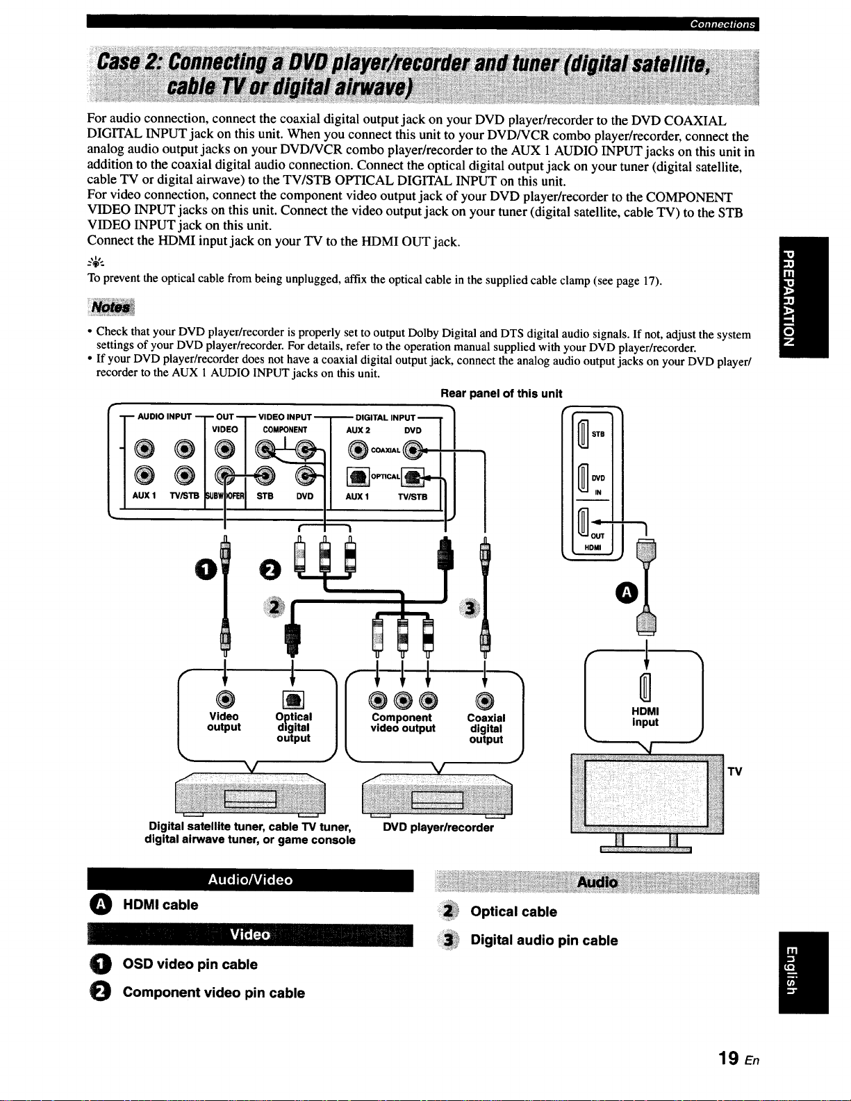
_.]alJl:1_#[Olt_
For audio connection, connect the coaxial digital output jack on your DVD player/recorder to the DVD COAXIAL
DIGITAL INPUT jack on this unit. When you connect this unit to your DVD/VCR combo player/recorder, connect the
analog audio output jacks on your DVD/VCR combo player/recorder to the AUX 1AUDIO INPUT jacks on this unit in
addition to the coaxial digital audio connection. Connect the optical digital output jack on your tuner (digital satellite,
cable TV or digital airwave) to the TV/STB OPTICAL DIGITAL INPUT on this unit.
For video connection, connect the component video output jack of your DVD player/recorder to the COMPONENT
VIDEO INPUT jacks on this unit. Connect the video output jack on your tuner (digital satellite, cable TV) to the STB
VIDEO INPUT jack on this unit.
Connect the HDMI input jack on your TV to the HDMI OUT jack.
_%,..
To prevent the optical cable from being unplugged, affix the optical cable in the supplied cable clamp (see page 17).
• Check that your DVD player/recorder is properly set to output Dolby Digital and DTS digital audio signals. If not, adjust the system
settings of your DVD player/recorder. For details, refer to the operation manual supplied with your DVD player/recorder.
• If your DVD player/recorder does not have a coaxial digital output jack, connect the analog audio output jacks on your DVD player/
recorder to the AUX 1 AUDIO INPUT jacks on this unit.
Rear panel of this unit
AUDIO INPUT T O
®
AUX 1 TV,_T13 _e_
0 0
Video Optical
output digital
output
DVD
TV/STB
L C_emoP°untepnutt
®
Coaxial
digital
'1
output
0
Digital satellite tuner, cable TV tuner,
digital airwave tuner, or game console
O HDMI cable
O OSD video pin cable
O Component video pin cable
DVD playerlrecorder
Optical cable
Digital audio pin cable
19 E.
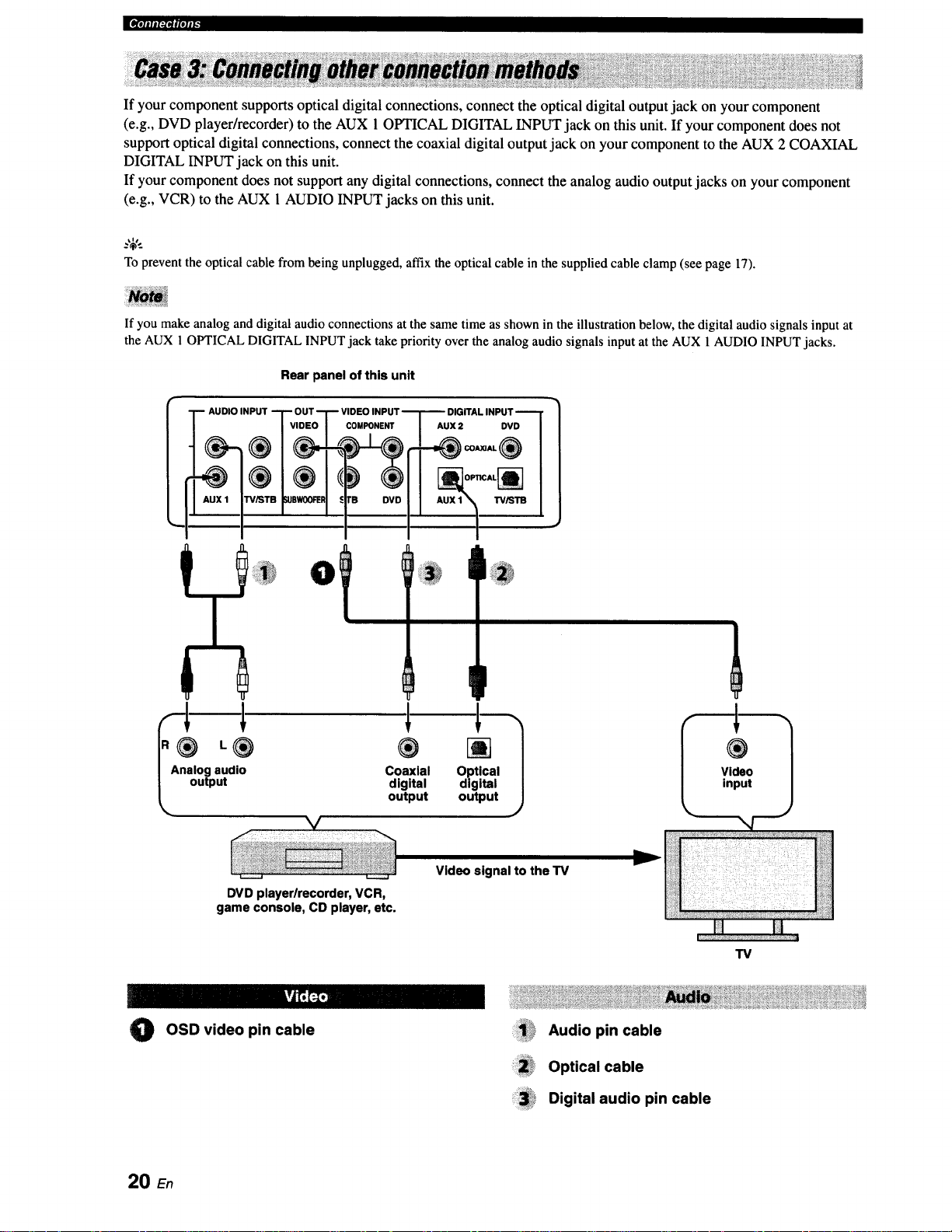
|¶'ililI:PII|'tlI"
If your component supports optical digital connections, connect the optical digital output jack on your component
(e.g., DVD player/recorder) to the AUX 1 OPTICAL DIGITAL INPUT jack on this unit. If your component does not
support optical digital connections, connect the coaxial digital output jack on your component to the AUX 2 COAXIAL
DIGITAL INPUT jack on this unit.
If your component does not support any digital connections, connect the analog audio output jacks on your component
(e.g., VCR) to the AUX 1AUDIO INPUT jacks on this unit.
Toprevent the optical cablefrom beingunplugged, affixthe opticalcable in the suppliedcable clamp (see page 17).
If you make analog and digital audio connections at the same time as shown in the illustration below, the digital audio signals input at
the AUX 1 OPTICAL DIGITAL INPUT jack take priority over the analog audio signals input at the AUX 1 AUDIO INPUT jacks.
Rear panel of this unit
DIGITAL INPUT
AUX 2 DVD
L® ®
I Analog audio Coaxial
_, output output
DVD player/recorder, VCR,
game console, CD player, etc.
kvJt';_
OSD video pin cable
0
digital
IP
[]
Optical
digital
output
Video signal to the TV
ii!!!!i!_i!_Audiopincable
:i:ii!i!_,Optical cable
_3_i* Digital audio pin cable
f
®
Video
input
TV
20 En
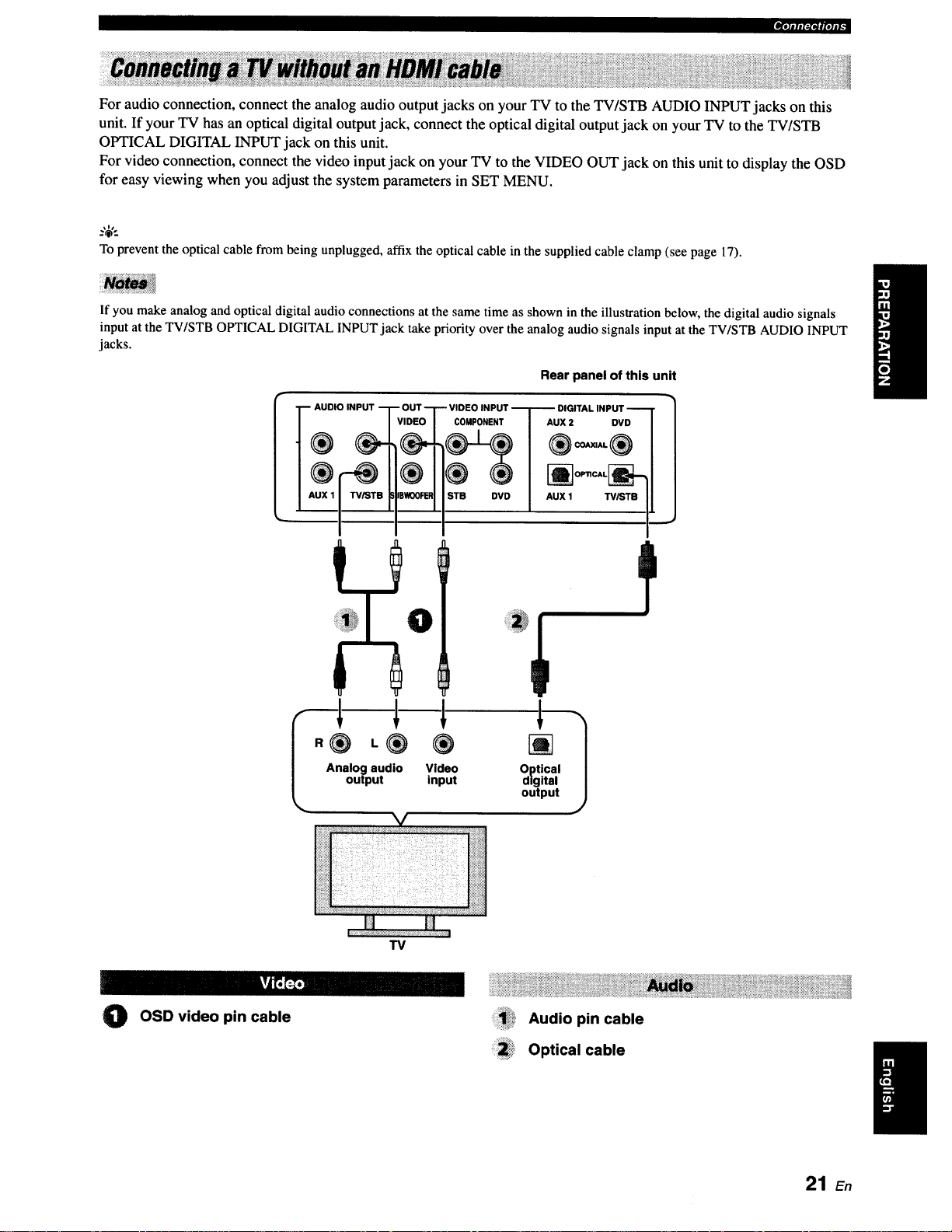
_,1-J_,VfpJiF
For audio connection, connect the analog audio output jacks on your TV to the TV/STB AUDIO INPUT jacks on this
unit. If your TV has an optical digital output jack, connect the optical digital output jack on your TV to the TV/STB
OPTICAL DIGITAL INPUT jack on this unit.
For video connection, connect the video input jack on your TV to the VIDEO OUT jack on this unit to display the OSD
for easy viewing when you adjust the system parameters in SET MENU.
.%',.
To prevent the optical cable from being unplugged, affix the optical cable in the supplied cable clamp (see page 17).
If you make analog and optical digital audio connections at the same time as shown in the illustration below, the digital audio signals
input at the TV/STB OPTICAL DIGITAL INPUT jack take priority over the analog audio signals input at the TV/STB AUDIO INPUT
jacks.
Rear panel of this unit
AUDIO INPUT
Analog audio Video Optical
output input digital
COMPONENT
STB DVD
output
_ OPTICAL_
- u x'7
AUX 1 W/STB I,
1
TV
O OSD video pin cable Audio pin cable
Optical cable
21 E.
J[IV[I]IIII_I_|(ll|[_
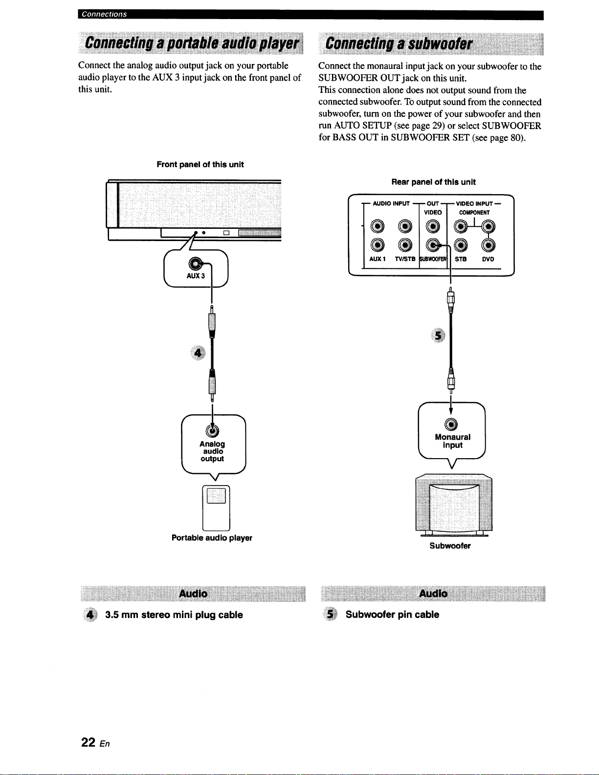
Connect the analog audio output jack on your portable
audio player to the AUX 3 input jack on the front panel of
this unit.
Front panel of this unit
I jp o [] I:++++++;+++++,%_+++++?:_++
r/+
Connect the monaural input jack on your subwoofer to the
SUBWOOFER OUT jack on this unit.
This connection alone does not output sound from the
connected subwoofer. To output sound from the connected
subwoofer, turn on the power of your subwoofer and then
run AUTO SETUP (see page 29) or select SUBWOOFER
for BASS OUT in SUBWOOFER SET (see page 80).
Rear panel of this unit
-+D,OINP+T?S°
AUX 1 TViST WOOFEI_
-- VIDEO INPUT --
COMPONENT
STB DVD
Portable audio player
3.5 mm stereo mini plug cable
22 En
Subwoofer
Subwoofer pin cable
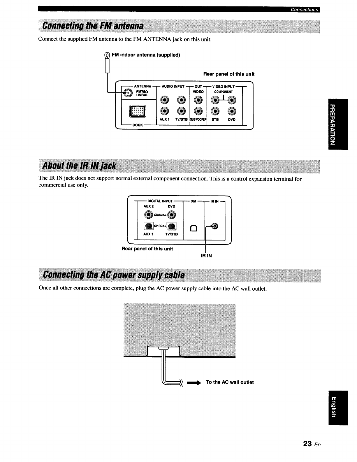
Connect the supplied FM antenna to the FM ANTENNA jack on this unit.
_'*itl#l:l*lglolll.
FM indoor antenna (supplied)
I r F'_--_ ANTENNA I_ AUDIO INPUT "-1" OUT "_ VIDEO INPUT "_[ _
Rear panel of this unit
It
II Q/® ®/®1®®1
I / I,UXl _.pw®_ I s_e ovo/
_ DOCK _ t e l
The IR IN jack does not support normal external component connection. This is a control expansion terminal for
commercial use only.
I Aux= ovo I /
I ®c-_®I |
I --]'--" DIGITAL INPUT "--T-- XM --T
I "ux' _'°1 /
IR IN 1
Rear panel of this unit
IR IN
Once all other connections are complete, plug the AC power supply cable into the AC wall outlet.
To the AC wall outlet
23 En
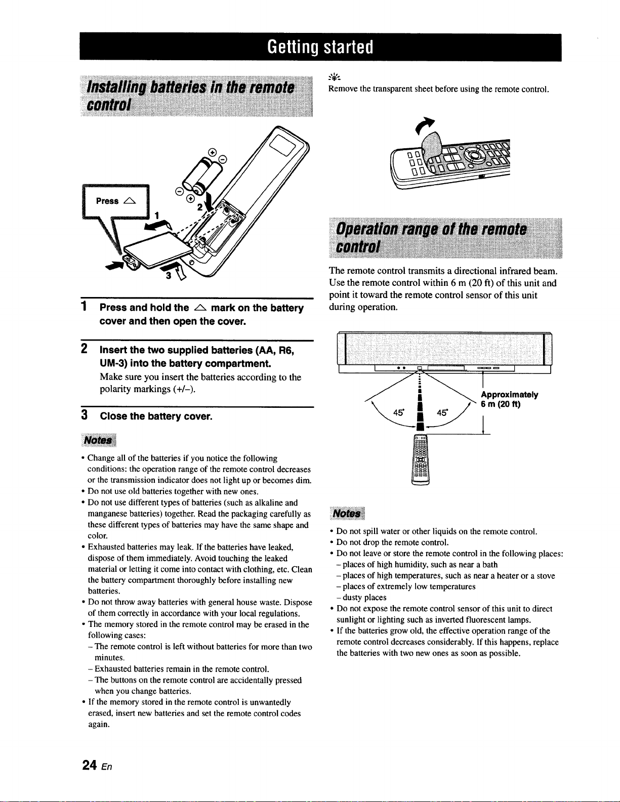
Press and hold the /_ mark on the battery
cover and then open the coven
2
Insert the two supplied batteries (AA, R6,
UM-3) into the battery compartment.
Make sure you insert the batteries according to the
polarity markings (+/-).
Remove the transparent sheet before using the remote control.
The remote control transmits a directional infrared beam.
Use the remote control within 6 m (20 ft) of this unit and
point it toward the remote control sensor of this unit
during operation.
3 Close the battery cover.
• Change all of the batteries if you notice the following
conditions: the operation range of the remote control decreases
or the transmission indicator does not light up or becomes dim.
• Do not use old batteries together with new ones.
• Do not use different types of batteries (such as alkaline and
manganese batteries) together. Read the packaging carefully as
these different types of batteries may have the same shape and
color.
• Exhausted batteries may leak. If the batteries have leaked,
dispose of them immediately. Avoid touching the leaked
material or letting it come into contact with clothing, etc. Clean
the battery compartment thoroughly before installing new
batteries.
• Do not throw away batteries with general house waste. Dispose
of them correctly inaccordance with your local regulations.
• The memory stored in the remote control may be erased in the
following cases:
- The remote control is left without batteries for more than two
minutes.
- Exhausted batteries remain in the remote control.
- The buttons on the remote control are accidentally pressed
when you change batteries.
• If the memory stored in the remote control is unwantedly
erased, insert new batteries and set the remote control codes
again.
l
• Do not spill water or other liquids on the remote control.
• Do not drop the remote control.
• Do not leave or store the remote control in the following places:
- places of high humidity, such as near a bath
- places of high temperatures, such as near a heater or a stove
- places of extremely low temperatures
- dusty places
• Do not expose the remote control sensor of this unit to direct
sunlight or lighting such as inverted fluorescent lamps.
• If the batteries grow old, the effective operation range of the
remote control decreases considerably. If this happens, replace
the batteries with two new ones as soon as possible.
24 En

2 Press STANDBY/ON again to set this unit to
the standby mode.
When this unit is in the standby mode, only STANDBY/ON on
the front panel or on the remote control is operational, and the
other control buttons on the front panel or on the remote control
are not operational until the power of this unit is turned on.
Press STANDBY/ON to turn on the power of
this unit.
The volume level appears in the front panel display,
and the current input source and beam mode are
displayed.
STANDBY/ON
[[ STANDBY/ON_ or
Front panel Remote control
+
I
IUOLUr'IE 30 I
I
Current volume level
+
_TL._.."STBjtH'.,.' fUR i
I 1
Current input Current beam
source mode
25 En
This section describes how to display the OSD (on-screen display) of this unit on your TV screen and to set the
parameters for your listening room. Once this is complete, you can enjoy real surround sound while watching TV in the
comfort of your own home.
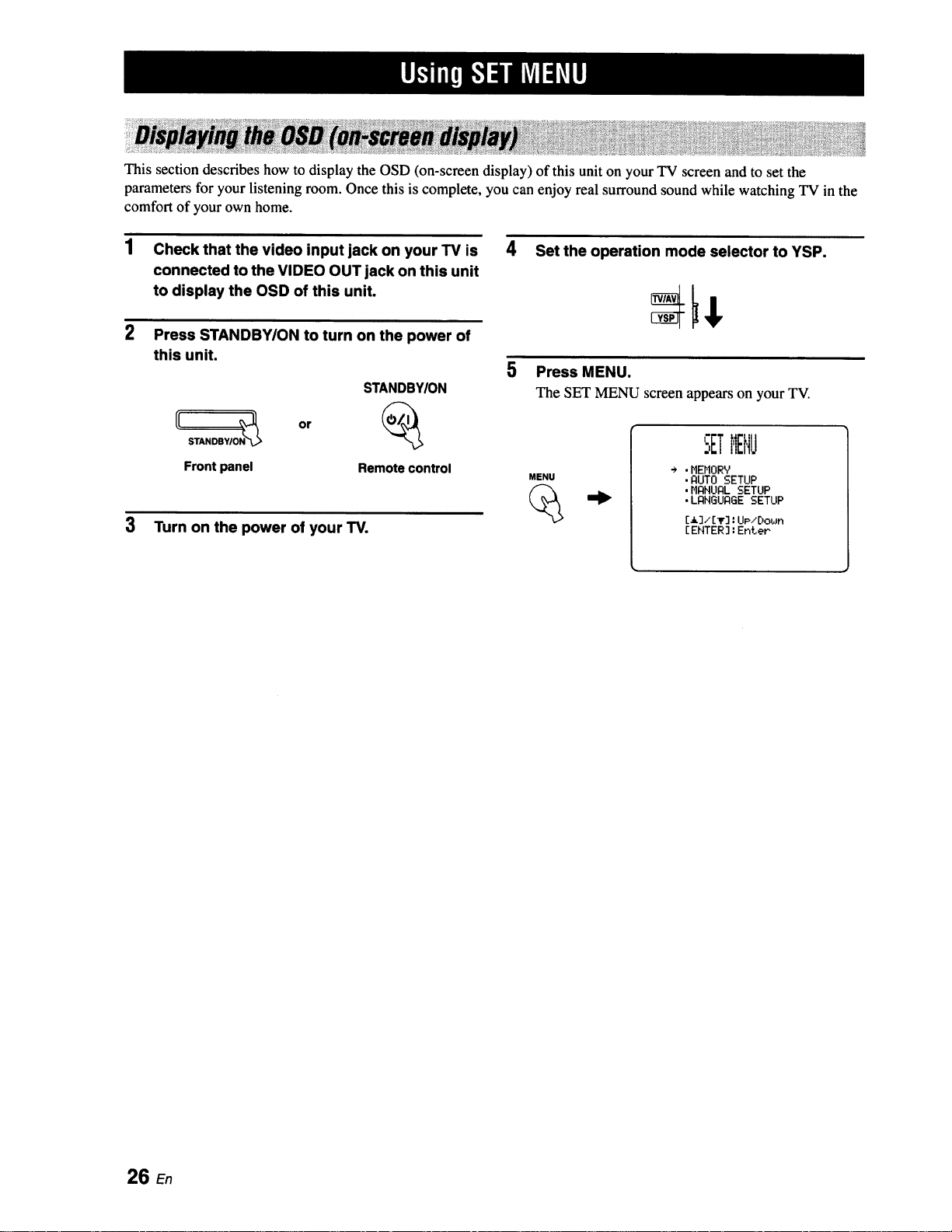
1 Check that the video input jack on your TV is 4
connected to the VIDEO OUT jack on this unit
to display the OSD of this unit.
2 Press STANDBWON to turn on the power of
this unit.
STANDBYION
Front panel Remote control
3 Turn on the power of your TV.
Set the operation mode selector to YSP.
5 Press MENU.
The SET MENU screen appears on your TV.
SETMENU
MENU
÷ .HEHORY
• AUTO SETUP
,MANUAL SETUP
• LANGUAGE SETUP
[13/[lr]: UP/E)obJn
[ ENTER] : Enter
26 En
 Loading...