

Yamaha YSP-1 User Manual

YSP-1
Digital Sound Projector
Système Acoustique Numérique
G
OWNER'S MANUAL
MODE D'EMPLOI
BEDIENUNGSANLEITUNG
BRUKSANVISNING
MANUALE DI ISTRUZIONI
MANUAL DE INSTRUCCIONES
GEBRUIKSAANWIJZING

CAUTION: READ THIS BEFORE OPERATING YOUR UNIT.
1 To assure the finest performance, please read this manual
carefully. Keep it in a safe place for future reference.
2 Install this sound system in a well ventilated, cool, dry, clean
place with at least 5 cm of space above (or below) YSP-1 – away
from direct sunlight, heat sources, vibration, dust, moisture, and/
or cold.
3 Locate this unit away from other electrical appliances, motors, or
transformers to avoid humming sounds.
4 Do not expose this unit to sudden temperature changes from cold
to hot, and do not locate this unit in an environment with high
humidity (i.e. a room with a humidifier) to prevent condensation
inside this unit, which may cause an electrical shock, fire,
damage to this unit, and/or personal injury.
5 Avoid installing this unit where foreign object may fall onto this
unit and/or this unit may be exposed to liquid dripping or
splashing. On the top of this unit, do not place:
– Other components, as they may cause damage and/or
discoloration on the surface of this unit.
– Burning objects (i.e. candles), as they may cause fire, damage
to this unit, and/or personal injury.
– Containers with liquid in them, as they may fall and liquid
may cause electrical shock to the user and/or damage to this
unit.
6 Do not cover this unit with a newspaper, tablecloth, curtain, etc.
in order not to obstruct heat radiation. If the temperature inside
this unit rises, it may cause fire, damage to this unit, and/or
personal injury.
7 Do not plug in this unit to a wall outlet until all connections are
complete.
8 Do not operate this unit upside-down. It may overheat, possibly
causing damage.
9 Do not use force on switches, knobs and/or cords.
10 When disconnecting the power cable from the wall outlet, grasp
the plug; do not pull the cable.
11 Do not clean this unit with chemical solvents; this might damage
the finish. Use a clean, dry cloth.
12 Only voltage specified on this unit must be used. Using this unit
with a higher voltage than specified is dangerous and may cause
fire, damage to this unit, and/or personal injury. YAMAHA will
not be held responsible for any damage resulting from use of this
unit with a voltage other than specified.
13 To prevent damage by lightning, disconnect the power cable from
the wall outlet during an electrical storm.
14 Do not attempt to modify or fix this unit. Contact qualified
YAMAHA service personnel when any service is needed.
The cabinet should never be opened for any reasons.
15 When not planning to use this unit for long periods of time (i.e.
vacation), disconnect the AC power plug from the wall outlet.
16 Be sure to read the “TROUBLESHOOTING” section on
common operating errors before concluding that this unit is
faulty.
17 Before moving this unit, press STANDBY/ON to set this unit in
standby mode, and disconnect the AC power plug from the wall
outlet.
18 Condensation will form when the surrounding temperature
changes suddenly. Disconnect the power cable from the outlet,
then leave the unit alone.
19 When using the unit for a long time, the unit may become warm.
Turn the power off, then leave the unit alone for cooling.
WARNING
TO REDUCE THE RISK OF FIRE OR ELECTRIC SHOCK,
DO NOT EXPOSE THIS APPLIANCE TO RAIN OR
MOISTURE.
This unit is not disconnected from the AC power source as
long as it is connected to the wall outlet, even if this unit itself
is turned off. This state is called the standby mode. In this
state, this unit is designed to consume a very small quantity of
power.
■ For U.K. customers
If the socket outlets in the home are not suitable for the plug
supplied with this appliance, it should be cut off and an
appropriate 3 pin plug fitted. For details, refer to the instructions
described below.
Note
The plug severed from the mains lead must be destroyed, as a
plug with bared flexible cord is hazardous if engaged in a live
socket outlet.
■ Special instructions for U.K. model
IMPORTANT
THE WIRES IN MAINS LEAD ARE COLOURED IN
ACCORDANCE WITH THE FOLLOWING CODE:
Blue: NEUTRAL
Brown: LIVE
As the colours of the wires in the mains lead of this apparatus may not correspond with the coloured markings
identifying the terminals in your plug, proceed as follows:
The wire which is coloured BLUE must be connected to
the terminal which is marked with the letter N or coloured
BLACK. The wire which is coloured BROWN must be
connected to the terminal which is marked with the letter L
or coloured RED.
Making sure that neither core is connected to the earth
terminal of the three pin plug.
i CAUTION

CAUTION
Danger of explosion if battery is incorrectly replaced.
Replace only with the same or equivalent type.
CAUTION
Use of controls or adjustments or performance of procedures
other than those specified herein may result in hazardous
radiation exposure.
CAUTION: READ THIS BEFORE OPERATING YOUR UNIT.
CAUTION ii

HOW TO USE THIS MANUAL
Check that you have received all of the supplied accessories.
(See “Supplied accessories” on page 4.)
Install this unit in your listening room.
(See “INSTALLING THIS UNIT IN YOUR LISTENING ROOM” on page 9.)
Connect this unit to your TV and other external components.
(See “CONNECTIONS” on page 11.)
Prepare the remote control and turn on this unit.
(See “PREPARING THE REMOTE CONTROL” on page 18 and “BASIC OPERATION” on page 19.)
Follow the steps to enjoying surround sound or make EASY SETUP settings.
(See “STEPS TO ENJOYING SURROUND SOUND” on page 20 or “EASY SETUP” on page 24.)
Play back a source and adjust the beam mode settings.
(See “PLAYBACK” on page 31 and “ADJUSTING BEAM MODE SETTINGS” on page 34.)
To make additional settings and adjustments:
Make MANUAL SETUP settings and set remote control codes.
(See “MANUAL SETUP” on page 36 and “REMOTE CONTROL FEATURES” on page 51.)
iii

CONTENTS
INTRODUCTION
OVERVIEW ...........................................................2
Selecting a listening room ......................................... 4
About this manual...................................................... 4
Supplied accessories.................................................. 4
CONTROLS AND FUNCTIONS .........................5
Front panel................................................................. 5
Front panel display .................................................... 6
Bottom panel..............................................................7
Remote control...........................................................8
PREPARATION
INSTALLING THIS UNIT IN YOUR
LISTENING ROOM.......................................... 9
Choosing an installation location............................... 9
Using a metal wall bracket ...................................... 10
Using a stand............................................................10
Using a rack.............................................................10
Affixing this unit...................................................... 10
CONNECTIONS ..................................................11
Connecting a TV...................................................... 12
Connecting a DVD player/recorder......................... 13
Connecting a VCR................................................... 14
Connecting other external components ...................15
Connecting a subwoofer.......................................... 16
Connecting the power supply cable ......................... 17
About the RS-232C terminal................................... 17
ADVANCED OPERATION
MANUAL SETUP.................................................36
Using SET MENU................................................... 37
SOUND MENU....................................................... 38
BEAM MENU......................................................... 40
INPUT MENU......................................................... 44
OPTION MENU...................................................... 45
SELECTING AN INPUT MODE........................47
MANUALLY ADJUSTING OUTPUT
LEVELS.............................................................48
Using the test tone ................................................... 48
Adjusting output levels during playback................. 49
USING THE SLEEP TIMER ..............................50
ADDITIONAL INFORMATION
REMOTE CONTROL FEATURES ...................51
Setting remote control codes ................................... 51
Controlling other components ................................. 52
TROUBLESHOOTING .......................................54
RESETTING THE FACTORY PRESETS ........57
FRONT PANEL DISPLAY ITEMS....................58
GLOSSARY...........................................................59
Audio formats.......................................................... 59
Audio information ................................................... 59
INDEX....................................................................60
SPECIFICATIONS...............................................61
PREPARATIONINTRODUCTION
OPERATION
OPERATION
BASIC
ADVANCED
BASIC OPERATION
PREPARING THE REMOTE CONTROL ....... 18
Installing batteries in the remote control................. 18
BASIC OPERATION........................................... 19
Using the remote control .........................................19
Turning the power on/to standby mode................... 19
STEPS TO ENJOYING SURROUND
SOUND
.................................................................. 20
Displaying the on-screen display (OSD)................. 20
Selecting a preset listening environment.................21
Enjoying TV in surround sound .............................. 22
EASY SETUP........................................................ 24
Using EASY SETUP ............................................... 24
VOLUME CONTROLS....................................... 30
Adjusting the volume............................................... 30
Muting the sound..................................................... 30
PLAYBACK.......................................................... 31
Selecting an input source.........................................31
Playing back sources................................................31
SELECTING A SURROUND MODE ................ 32
Playback sources and their available surround
modes...................................................................32
Enjoying 2-channel sources with multi channels .... 32
Surround mode parameters...................................... 33
ADDITIONAL PLAYBACK MODES ...............33
Night listening modes.............................................. 33
ADJUSTING BEAM MODE SETTINGS.......... 34
Stereo mode ............................................................. 34
3 beam mode............................................................ 34
5 beam mode............................................................ 34
ST(STEREO)+3 beam mode................................... 35
INFORMATION
English
ADDITIONAL
1
OVERVIEW
OVERVIEW
It is generally accepted that in order to fully enjoy the benefits of surround sound at home, you must endure the agony of
wiring and installing a great number of speakers in the hope that your listening room will give you the same kind of
surround sound experience as your local movie theater.
YAMAHA’s YSP-1 Digital Sound Projector challenges this preconception that complicated speaker set up and
troublesome wiring go hand-in-hand with the enjoyment of multi-channel surround sound.
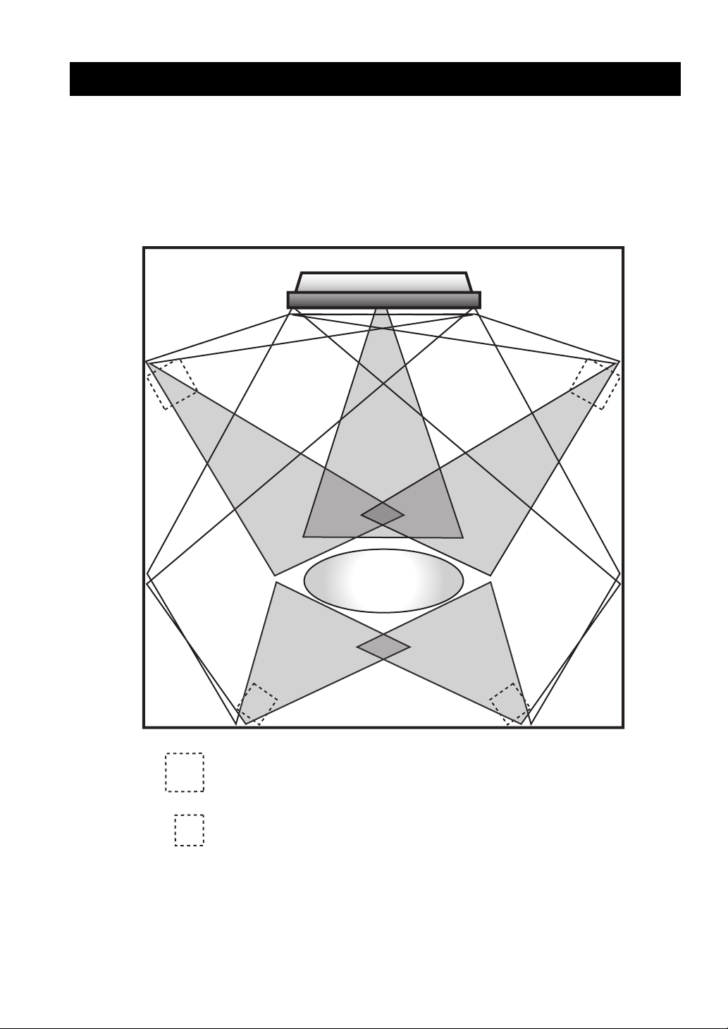
Sound Beam Diagram
C
L
Listening
Position
SL
Imaginary front speaker position
Imaginary surround speaker position
R
SR
2

OVERVIEW
This slimline unit does away with the need for complicated wiring and installation worries, leaving you with a unit that is
not only easy to set up, but which is also capable of reproducing the kind of powerful surround sound you have been
waiting for from its built-in subwoofers (2) and individual speakers (40).
You can use this unit’s parameters to fine tune the delay time for separate sound beams, resulting in highly directional
sound that comes in on the listening position from all directions.
The YSP-1 projects sound beams containing surround sound information for the front right (R), front left (L), surround
right (SR) and surround left (SL) speaker positions, which are reflected off the walls of your listening room before
reaching the actual listening position. With the addition of center (C) sound beams, this Digital Sound Projector creates
true-to-life 5.1 channel surround sound that makes you feel as if there are actual speakers around the room.
Further, you can change the way in which these beams are projected at your walls (the beam mode) to match the contents
of the program you are watching or your listening environment, giving you a virtual surround sound experience for both
stereo and 5.1-channel playback.
This unit’s SET MENU can be displayed on your TV screen, allowing you to customize this unit to suit your listening
environment. Set up is straight forward using the MEMORY or EASY SETUP menus. MEMORY allows you to load
preset listening environment parameters for quick setup. EASY SETUP is an easy-to-follow setup method for first-time
users. In addition, the MANUAL SETUP menu offers advanced parameters for the surround sound enthusiast who wants
to make individual adjustments for each speaker position.
This highly-advanced projector supports a wide range of sound technology, including Dolby Digital, a basic audio format
for DVDs, Dolby Pro Logic for the reproduction of true-to-life sound, and DTS for playback of the best possible sound
clarity.
Equipped with two optical digital, one coaxial digital and two analog input jacks, the YSP-1 allows you to expand your
system through the direct connection of external components, such as a DVD player.
INTRODUCTION
Sit back and enjoy the real sound experience of this simple, yet stylish Digital Sound Projector.
English
3
OVERVIEW
Selecting a listening room
This unit creates surround sound by reflecting projected sound beams off the walls of your listening room. The surround
sound effects produced by this unit may not be sufficient when the unit is installed in the following locations:
• Rooms with surfaces inadequate for reflecting sound beams
• Rooms with acoustically absorbent surfaces
• Rooms with measurements outside the range: (3 to 7 m) × (2 to 3.5 m) × (3 to 7 m) (W × H × D)
• Rooms with less than 2 m from the listening position to the speaker positions
• Rooms where objects such as furniture are likely to obstruct the path of sound beams
About this manual
• This manual describes how to connect and operate the YSP-1. For details regarding the operation of external
components, refer to the supplied owner’s manual for the component.
• Some operations can be performed by using either the buttons on the main unit or on the remote control. In such cases,
the operation is described using remote control operation.
• y indicates a tip for your operation.
• This manual is printed prior to production. Design and specifications are subject to change in part as a result of
improvements, etc. In case of differences between the manual and product, the product has priority.
Manufactured under license from Dolby Laboratories.
“Dolby”, “Pro Logic”, and the double-D symbol are trademarks
of Dolby Laboratories.
“DTS”, and “Neo:6” are trademarks of Digital Theater Systems,
Inc.
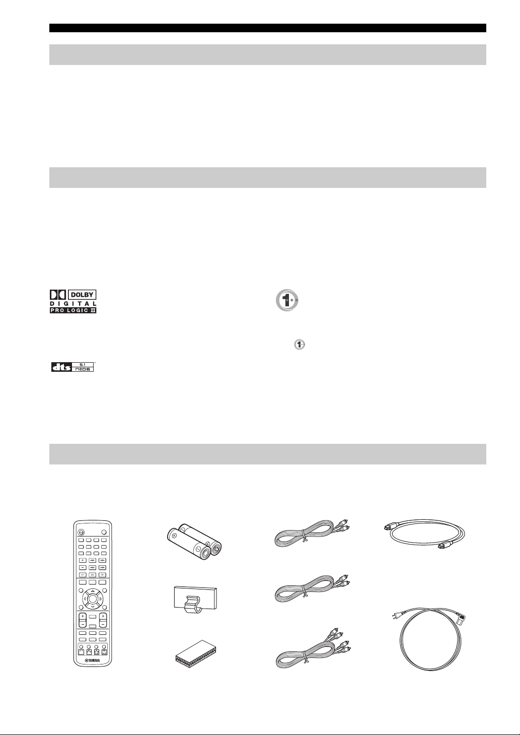
Supplied accessories
Please check that you received all of the following parts.
Remote control (×1)
STANDBY/ON
POWER
AV
2341
6785
CODE SET
0 +109
CH
SURROUND
NIGHT
SET MENU
CH LEVEL MENU
SELECT
RETURN
TEST
VOLUME
TV VOL
MUTE
TV MUTE
TV INPUT TV DVD
VCRSLEEP
AUX
BEAM MODE
Batteries (×2)
(AA, R6, UM-3)
Cable Holder (×1)
Fastener (×4)
Manufactured under license from 1 Ltd. world-wide patents
applied for.
The “ ” logo and “Digital Sound Projector” are trademarks of
1 Ltd.
OSD Video Cable (×1)
Optical Cable (×1)
Digital Audio Pin Cable (×1)
Power Cable (×1)
Audio Pin Cable (×1)
4
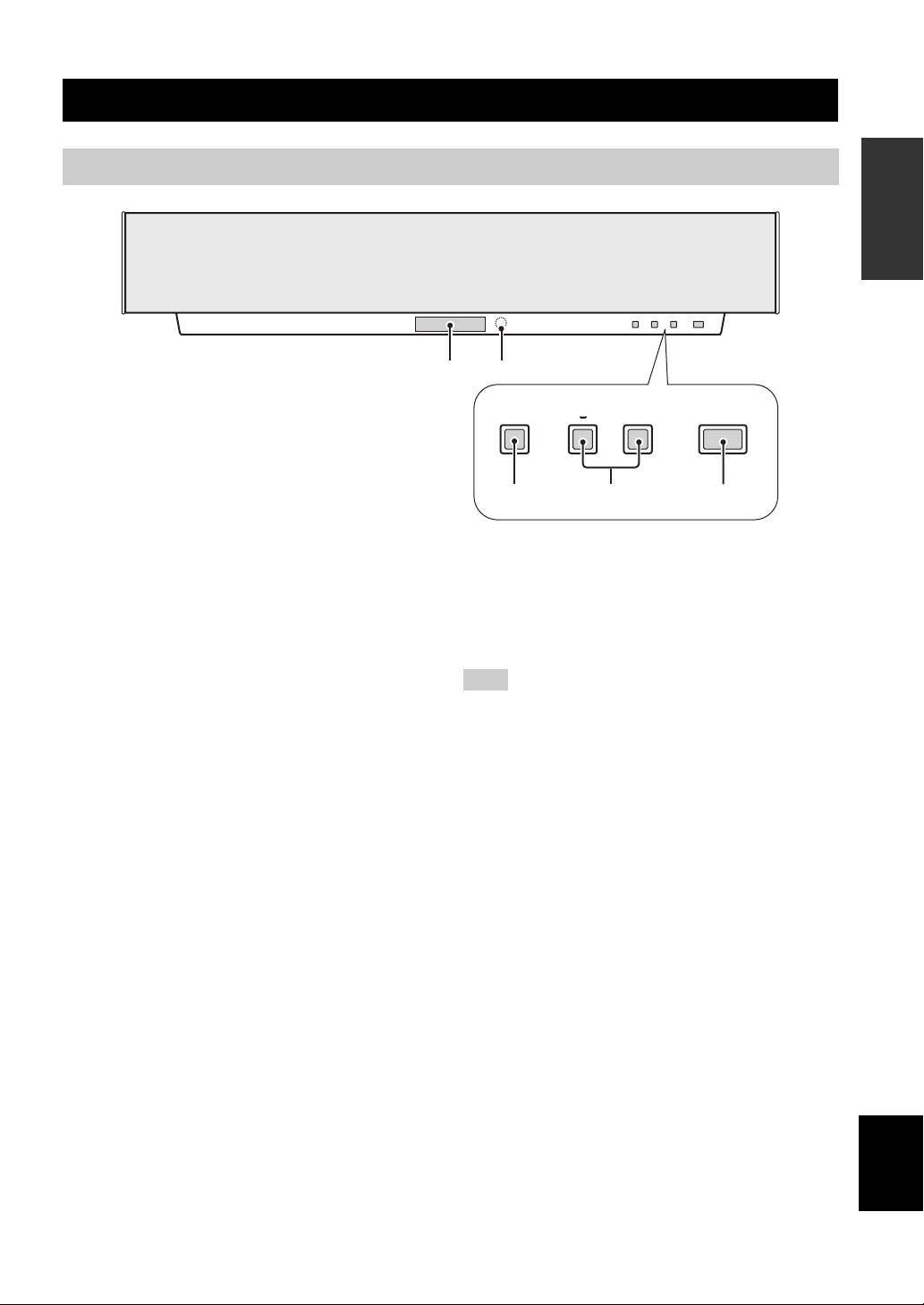
Front panel
CONTROLS AND FUNCTIONS
1
2
CONTROLS AND FUNCTIONS
INTRODUCTION
1 Front panel display
Shows information about the operational status of this
unit.
2 Remote control sensor
Receives signals from the remote control.
3 INPUT
Switches between the connected external audio sources.
4 VOLUME –/+
Controls the output level of all audio channels (see
page 30).
INPUT
3 4
+
+
STANDBY/ONVOLUME
5
5 STANDBY/ON
Turns on this unit or sets it in the standby mode (see
page 19). When you turn on this unit, you will hear a click
and there will be a 4 to 5-second delay before it can
reproduce sound.
Note
In standby mode, this unit consumes a small amount of power in
order to receive infrared-signals from the remote control.
English
5
CONTROLS AND FUNCTIONS
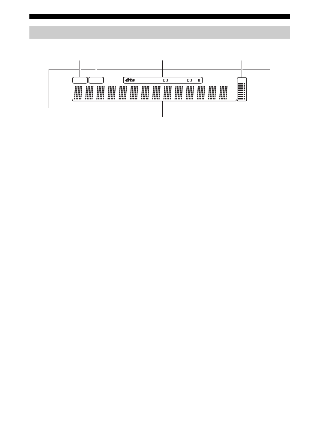
Front panel display
412 3
NIGHT SLEEP PCM PL
1 NIGHT indicator
Lights up when you select a night listening mode (see
page 33).
2 SLEEP indicator
Lights up while the sleep timer is on (see page 50).
3 Decoder indicators
When any of this unit’s decoders function, the respective
indicator lights up.
DIGITAL
m
ft
mS
dB
VOL
5
4 Volume level indication
Indicates the current volume level (see page 30).
5 Multi-information display
Shows information when adjusting or changing settings.
6
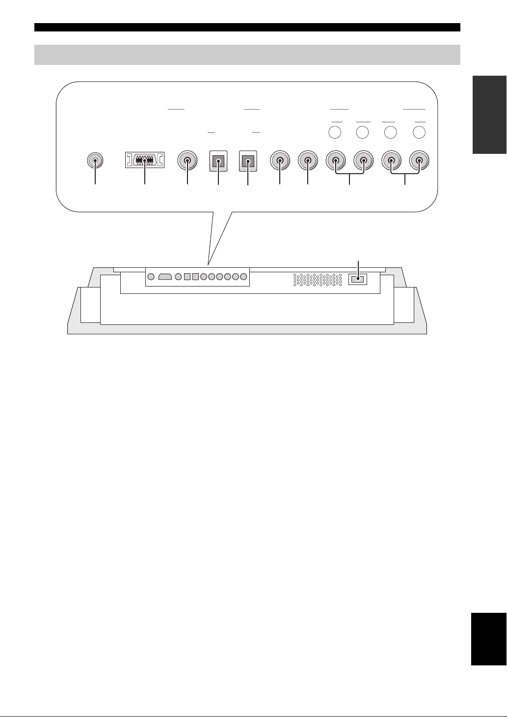
Bottom panel
CONTROLS AND FUNCTIONS
INTRODUCTION
DIGITAL INPUT
SYSTEM
CONNECTOR
1
1 SYSTEM CONNECTOR jack
Use to connect a YAMAHA subwoofer equipped with a
SYSTEM CONNECTOR jack to this unit (see page 16).
2 RS-232C terminal
This is a control expansion terminal for commercial use
only (see page 17).
3 DVD coaxial digital input jack
Use to connect a DVD player using a coaxial digital
connection (see page 13).
4 AUX optical digital input jack
Use to connect an external component using an optical
digital connection (see page 15).
5 TV optical digital input jack
Use to connect a TV using an optical digital connection
(see page 12).
RS-232C COAXIAL
DVD AUX TV TV VCR
OPTICAL R L R L
AUDIO INPUT
VIDEO
SUBWOOFER
OUT
5
6 VIDEO OUT jack
Connect to your TV’s video input terminal to display this
unit’s OSD (see page 12).
7 SUBWOOFER OUT jack
Use to connect a subwoofer (see page 16).
8 TV analog audio input jacks
Use to make an analog connection to your TV
(see page 12).
9 VCR analog audio input jacks
Use to make an analog connection to your VCR
(see page 14).
0 AC IN
Connect the supplied power cable (see page 17).
6
OUT
7
8
9342
0
English
7
CONTROLS AND FUNCTIONS
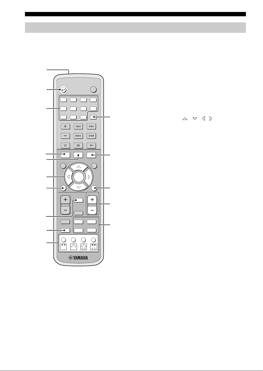
Remote control
This section describes the function of each control on the
remote control used to control this system. To operate
other components, see “Controlling other components” on
page 52.
1
2
3
4
5
6
7
STANDBY/ON
2341
6785
0 +109
CH
SURROUND
NIGHT
CH LEVEL MENU
TEST
TV VOL
SELECT
MUTE
POWER
AV
CODE SET
SET MENU
RETURN
VOLUME
A
B
C
D
TV MUTE
8
9
TV INPUT TV DVD
AUX
BEAM MODE
VCRSLEEP
E
0
1 Infrared window
Outputs infrared control signals. Aim this window at the
component you want to operate.
2 STANDBY/ON
Sets this system in the standby mode (see page 19).
3 Numeric buttons
Use to enter numbers.
4 NIGHT
Turns on or off the night listening modes (see page 33).
5 SURROUND
Selects the surround mode for playback (see page 32).
6 Cursor buttons / / / SELECT
Use to select and adjust SET MENU items.
7 TEST
Outputs a test tone when adjusting the speaker levels
(see page 48).
8 MUTE
Mutes the sound (see page 30). Press again to restore the
audio output to the previous volume level.
9 SLEEP
Sets the sleep timer (see page 50).
0 Beam mode buttons
Change the beam mode settings (see page 34).
A CODE SET
Use to set up remote control codes (see page 51).
B SET MENU
Displays the SET MENU on your TV or monitor
(see page 24).
C RETURN
Use to select sleep timer settings (see page 50) or return to
the previous SET MENU screen (see page 24).
D VOLUME +/–
Increases or decreases this system’s volume level
(see page 30).
E Input selector buttons
Use to select a playback source and change the control
area (see page 31).
8
INSTALLING THIS UNIT IN YOUR LISTENING ROOM
INSTALLING THIS UNIT IN YOUR LISTENING ROOM
This section describes how to choose a suitable installation location for this unit, and how to install the unit using either a
metal wall bracket, rack or stand.
Note
If objects such as furniture are obstructing the path of sound beams, the desired surround sound effects may not be achieved. Make sure
you install this unit where there are no objects in the path of sound beams.
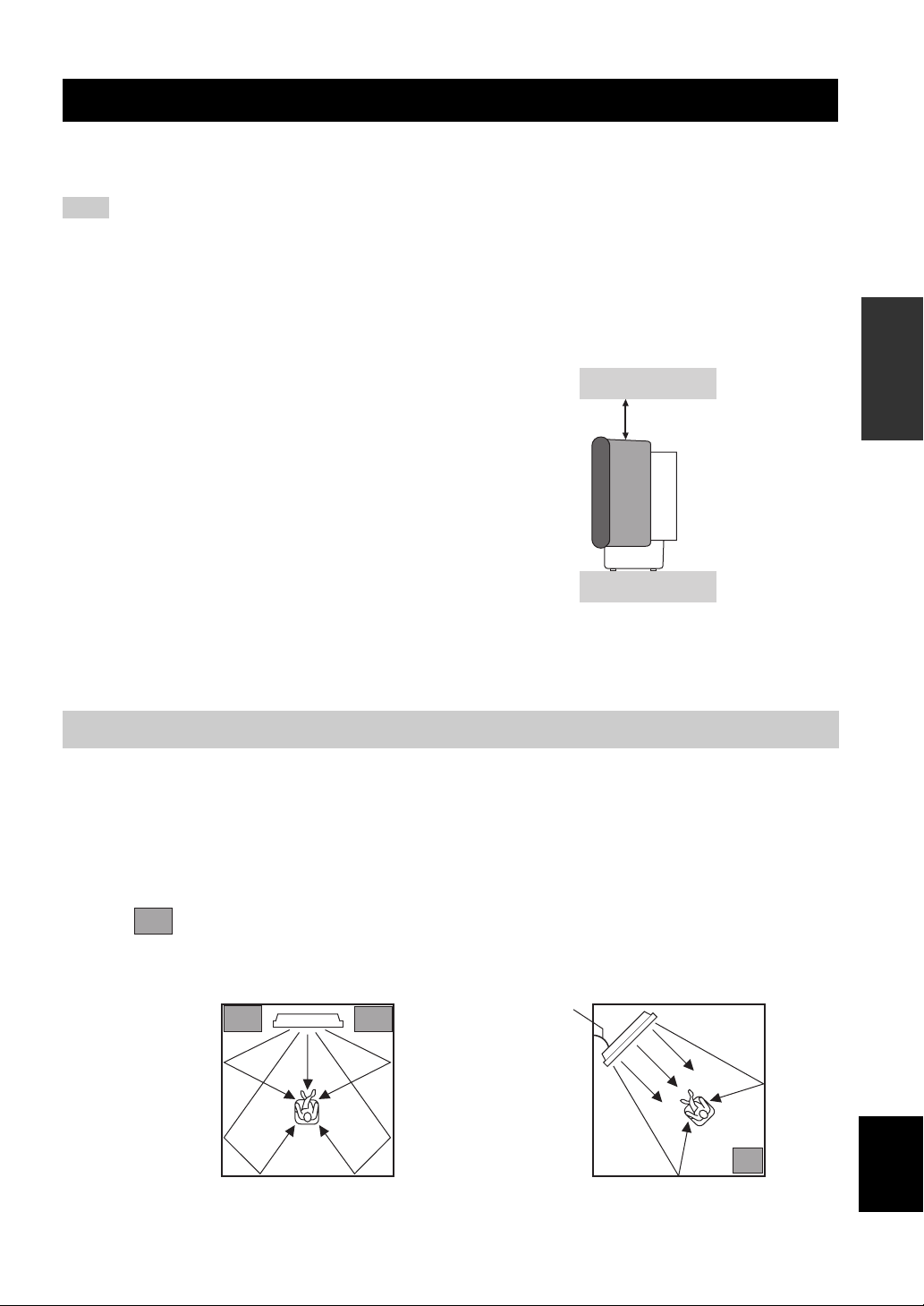
■ Notes on installation
• When installing this unit, be sure to leave an adequate
amount of ventilation space so that heat can escape.
Make sure you leave at least 5 cm of space above
(or below) this unit (as shown in the illustration on the
right).
• We do not recommend installing this unit so that it is
positioned directly on the floor of your listening room.
Please install this unit using a metal wall bracket, rack
or stand.
• This unit weighs 13 kg. Be sure to install this unit
where it will not fall if subject to vibrations, such as
from an earthquake, and where it is out of the reach of
children.
• When using a cathode-ray tube (CRT) TV, do not
install this unit directly above your TV.
• This unit is shielded against magnetic rays. However,
if the picture on your TV screen becomes blurred or
distorted, we recommend moving the speakers away
from your TV.
Front
5 cm or
more
Rear
Choosing an installation location
To experience the best surround sound this unit can deliver, make sure you install this unit in a location where objects,
such as furniture, are not in the direct path of the sound beams (see the illustration below).
When installing this unit parallel to the wall, try placing it so that it is in the exact center of the wall (measured from the
left and right corners).
When installing this unit in the corner of your listening room, make sure the speakers are placed between 40º to 50º from
the adjacent walls.
PREPARATION
An object, such as furniture
40° to 50°
English
9
INSTALLING THIS UNIT IN YOUR LISTENING ROOM
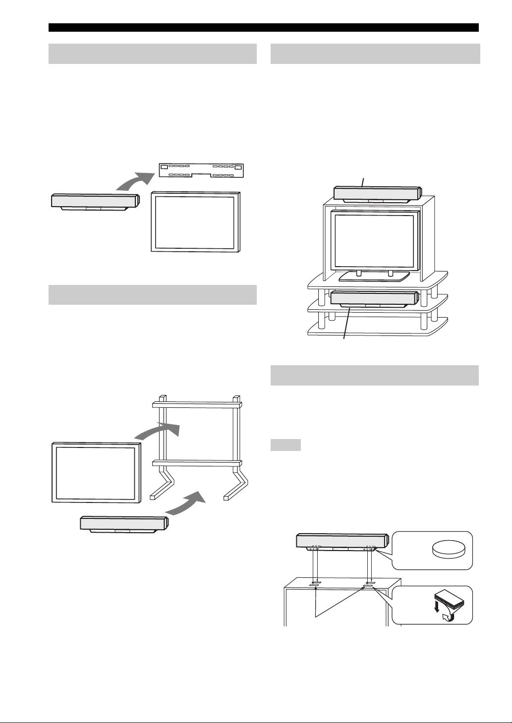
Using a metal wall bracket
You can use the optional metal wall bracket (SPM-K1) to
mount this system on your listening room wall.
For details on how to attach the metal bracket to the wall
or how to attach this system to the metal bracket, refer to
the instructions supplied with the bracket.
Metal wall bracket
(SPM-K1)
YSP-1
TV
Using a stand
You can mount your TV on a commercially available
stand placed on a rack to install this unit under your TV.
For details on how to attach the stand or how to attach this
system to your TV, refer to the instructions supplied with
the stand.
Using a rack
You can install this system either above or under your TV
in a commercially available rack.
Before installing, make sure that the rack is large enough
to allow adequate ventilation space around this unit, and
that it is strong enough to support the weight of both this
unit and your TV.
When the YSP-1 is
installed above your TV
TV
When the YSP-1 is
installed under your TV
Affixing this unit
TV
YSP-1
Stand
To affix this unit, remove the protection pads from the
bottom of the unit, then secure the supplied fasteners (4
pieces) to the bottom four corners of this unit and the top
of the rack, etc. as shown below.
Notes
• Do not install this unit on top of a slanted surface. This unit may
fall over and cause injury.
• Make sure you wipe the surface of the rack, etc. before securing
the fasteners. Appling the tape to a dirty or wet surface will
weaken the sticking power of the tape, and this unit may fall as
a result.
YSP-1
Remove the
protection
pads
Peel off
the film
Fasteners
10
CONNECTIONS
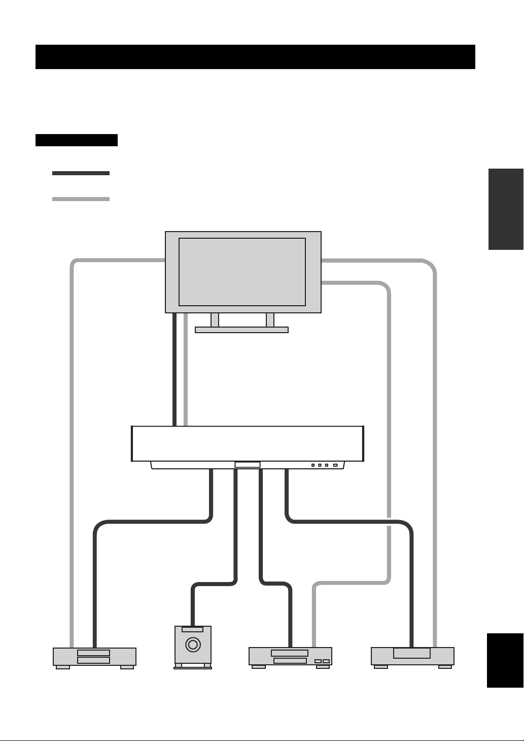
CONNECTIONS
This unit is equipped with two optical digital jacks, one coaxial digital jack and two types of analog jacks for connecting
external components such as your TV, DVD player, VCR and game console. Further, by connecting a subwoofer to this
unit, you can enjoy reinforced low bass sounds. For details on how to connect the various types of external components to
this unit, see pages 12 to 17.
CAUTION
Do not connect this unit or other components to the mains power until all connections between components are complete.
Audio connection
Video connection
TV
PREPARATION
DVD player
Subwoofer
YSP-1
VCR
English
Digital satellite tuner, cable TV or
game console
11
CONNECTIONS
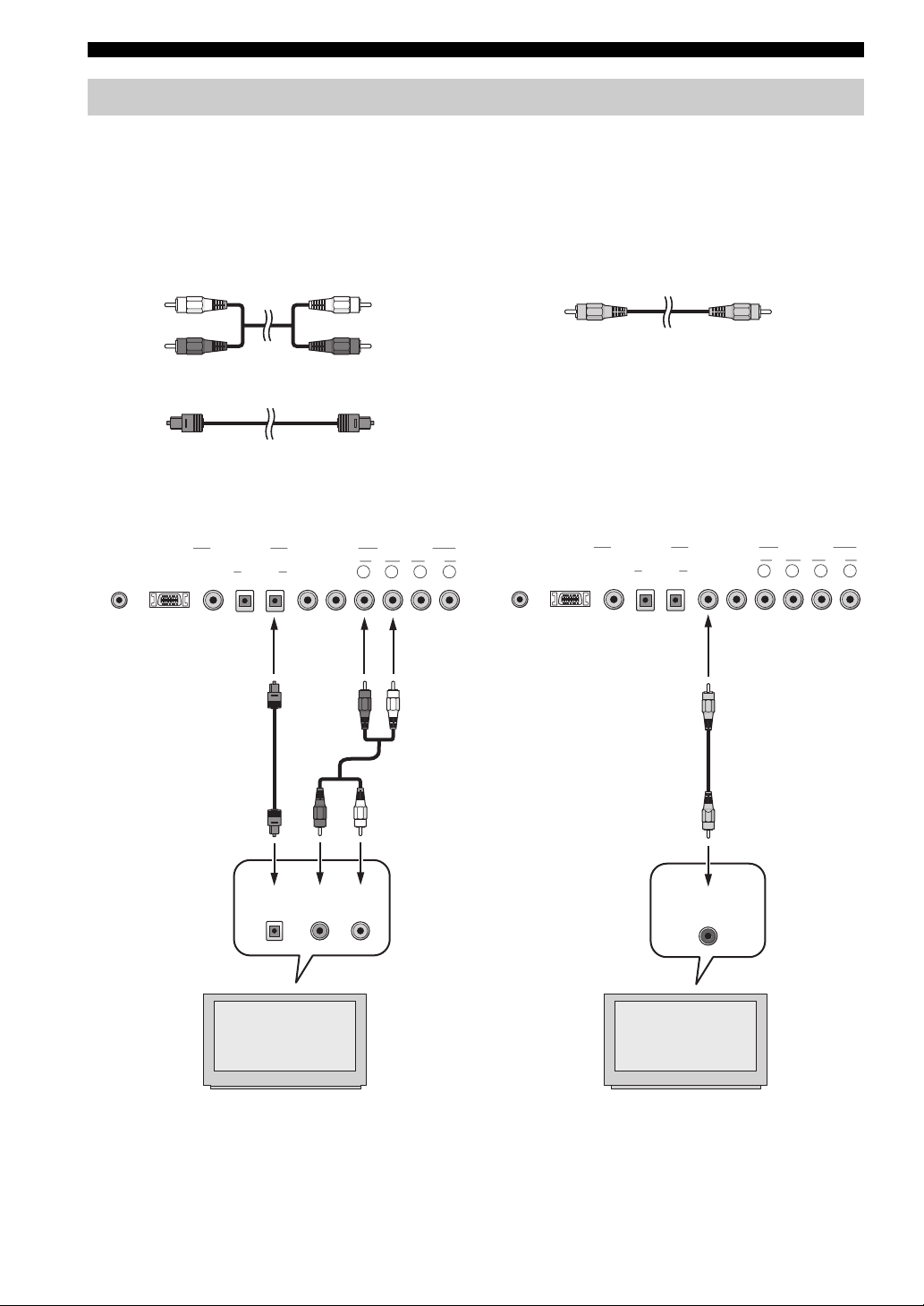
Connecting a TV
You can connect a TV to this unit and display the OSD for easy viewing (see page 20) when operating SET MENU (see
page 24). When connecting the Optical Cable, use the Cable Holder at the rear panel of the YSP-1 to fix the cable (see
page 15).
Cables used for connections
For digital connections For video (OSD) connections
Audio Pin Cable (supplied)
OSD Video Cable (supplied)
(White)
(Red)
(White)
(Red)
Optical Cable (supplied)
■ Digital and analog connections ■ Video (OSD) connections
SYSTEM
CONNECTOR
YSP-1 (Bottom panel)
DIGITAL INPUT
DVD AUX TV TV VCR
VIDEO
SUBWOOFER
OUT
OPTICAL R L R L
AUDIO INPUT
OUTRS-232C COAXIAL
SYSTEM
CONNECTOR
YSP-1 (Bottom panel)
DIGITAL INPUT
DVD AUX TV TV VCR
VIDEO
SUBWOOFER
OUT
OPTICAL R L R L
AUDIO INPUT
OUTRS-232C COAXIAL
12
Optical digital
output
TV
Analog audio
output
R L
TV
Video
input
CONNECTIONS
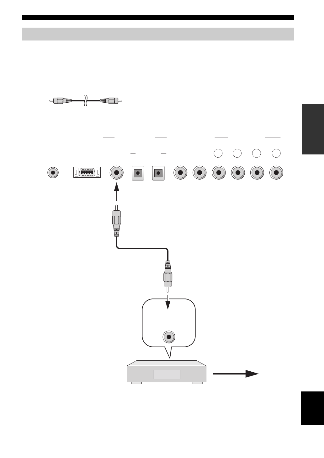
Connecting a DVD player/recorder
To connect a DVD player/recorder, connect the coaxial digital output jack on your DVD player to the coaxial digital
input jack (DVD COAXIAL) on this unit.
If there is no coaxial digital output jack on your DVD player/recorder, use them with optical digital connection.
Cables used for connections
Digital Audio Pin Cable (supplied)
YSP-1 (Bottom panel)
AUDIO INPUT
SYSTEM
CONNECTOR
DIGITAL INPUT
DVD AUX TV TV VCR
RS-232C COAXIAL
VIDEO
SUBWOOFER
OPTICAL R L R L
OUT
OUT
PREPARATION
Coaxial digital
output
DVD player/recorder
Video signal
to a TV
English
13
CONNECTIONS
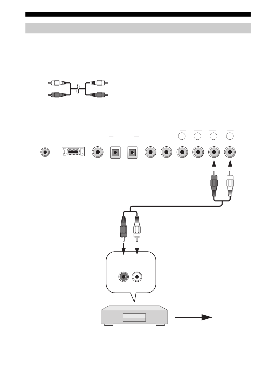
Connecting a VCR
To connect a VCR, connect the analog audio output jack on your VCR to the analog audio input jack (VCR R/L) on this
unit.
Connect red plugs to the right jacks and white plugs to the left jacks.
Cables used for connections
Audio Pin Cable
(White)
(Red)
SYSTEM
CONNECTOR
DIGITAL INPUT
DVD AUX TV TV VCR
RS-232C COAXIAL
(White)
(Red)
YSP-1 (Bottom panel)
AUDIO INPUT
VIDEO
SUBWOOFER
OPTICAL R L R L
(Red)
OUT
(White)
OUT
(Red)
(White)
14
Analog audio
output
R L
VCR
Video signal
to a TV
CONNECTIONS
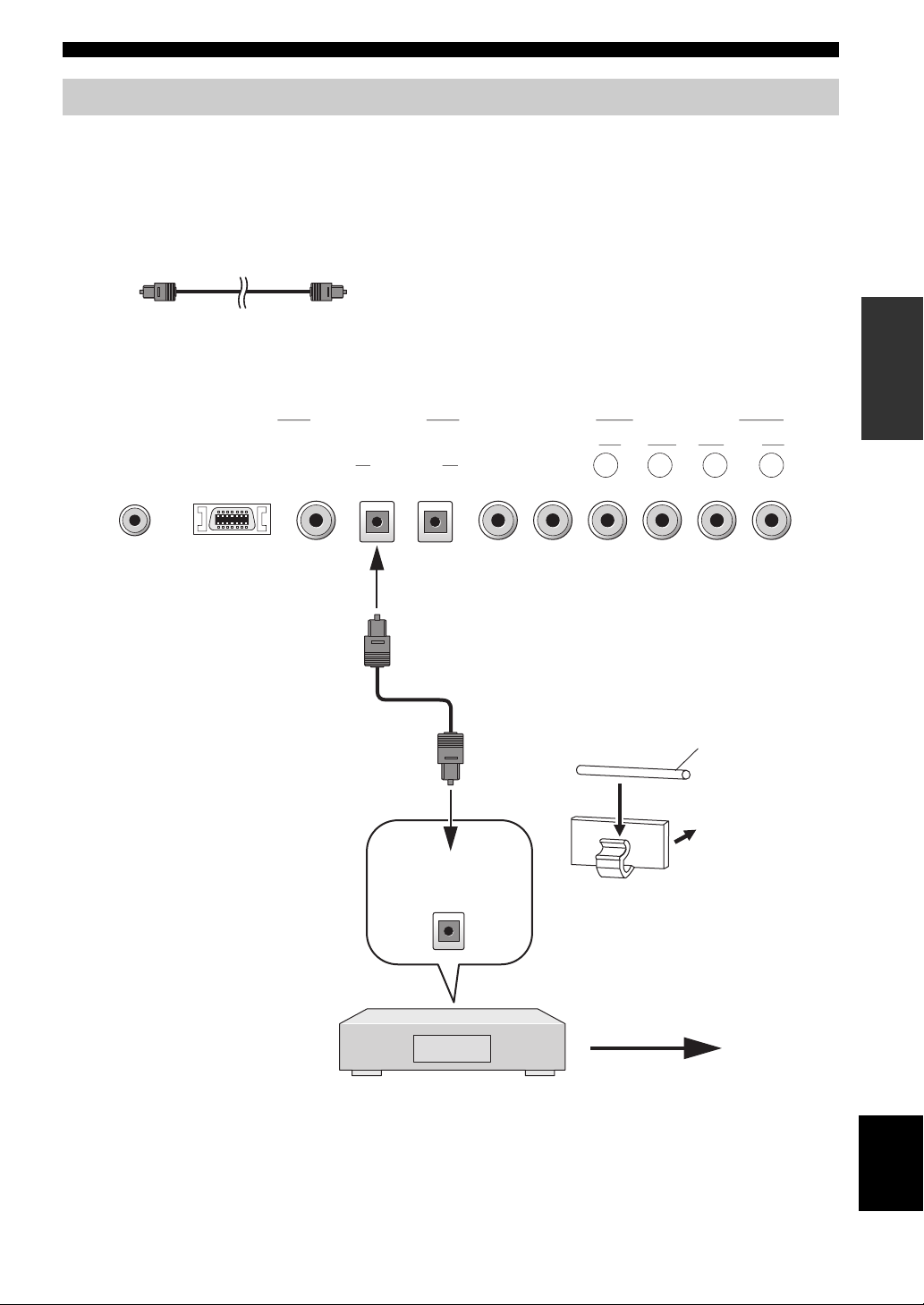
Connecting other external components
To connect other external components, connect the optical digital output jack on the component to the optical digital
input jack (AUX OPTICAL) on this unit.
You can connect a DVD player/recorder or a component that supports optical digital connections.
Cables used for connections
Optical Cable
YSP-1 (Bottom panel)
SYSTEM
CONNECTOR
DIGITAL INPUT
DVD AUX TV TV VCR
RS-232C COAXIAL
VIDEO
SUBWOOFER
OPTICAL R L R L
OUT
OUT
AUDIO INPUT
PREPARATION
To prevent cables from becoming
unplugged, place the cable holder
provided open side up, and attach
it to the rear panel of this unit in a
suitable position. Affix the
cable(s) in the holder.
Optical digital
output
Digital satellite tuner, cable TV or
game console
Optical fiber
cable
Attach to
the YSP-1
Video signal
to a TV
English
15
CONNECTIONS
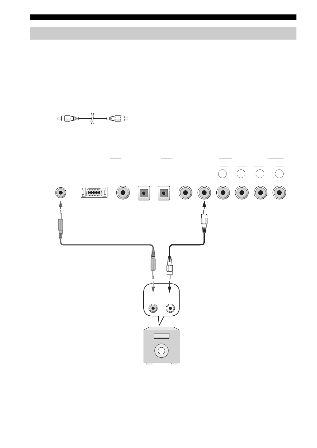
Connecting a subwoofer
To connect a subwoofer, connect the monaural input jack on your subwoofer to the monaural audio output jack
(SUBWOOFER OUT) on this unit.
When connecting a YAMAHA subwoofer equipped with a SYSTEM CONNECTOR jack, connect it to the SYSTEM
CONNECTOR jack on this unit. If the subwoofer is connected using a system type connection, changing the power mode
of this unit controls the power mode of the subwoofer.
To adjust the settings for your subwoofer, see SUBWOOFER SET in MANUAL SETUP (page 38).
Cables used for connections
Subwoofer pin cable
YSP-1 (Bottom panel)
AUDIO INPUT
SYSTEM
CONNECTOR
DIGITAL INPUT
DVD AUX TV TV VCR
RS-232C COAXIAL
VIDEO
SUBWOOFER
OPTICAL R L R L
OUT
OUT
16
System
connector
Subwoofer
Monaural
input
 Loading...