

Yamaha YRM-301 Owner's Manual
SINCE 1887
NIPPON GAKKI •CO.. LTD. HAMAMATSU. JAPAN
MIDI RELIT'Ll
OWNER'S \,/lANUA
im L,
m
on
ENRE6I3 NaJR. MIDI
MANUEL D'UTILISATION
•
•
101VID-137M1
85 09 4.0 CR Printed in Japan
4, •
3
S.
3
•
•
•
• NIPPDN GAKKI CO., LTD.
PRINTED IN JAPAN
.
encing of four or even more FM digital tone generators.
-1 capability.
ty permits modification of recorded tracks.
panual punch-in recording.
ty permits sequential playback of banks with tempo, transpose, track and MIDI i
es.
si
sidling system permits use of floppy disk or cassette tape for storage and retrieval
a.
ise compatible for exceptionally easy, fast operation.
II advantage of the many versatile features of this software package, we urge you
al thoroughly to familiarize yourself with the MIDI Recorder before use. A ls o , keep
so it can be referred to whenever
meyooard.
needed.
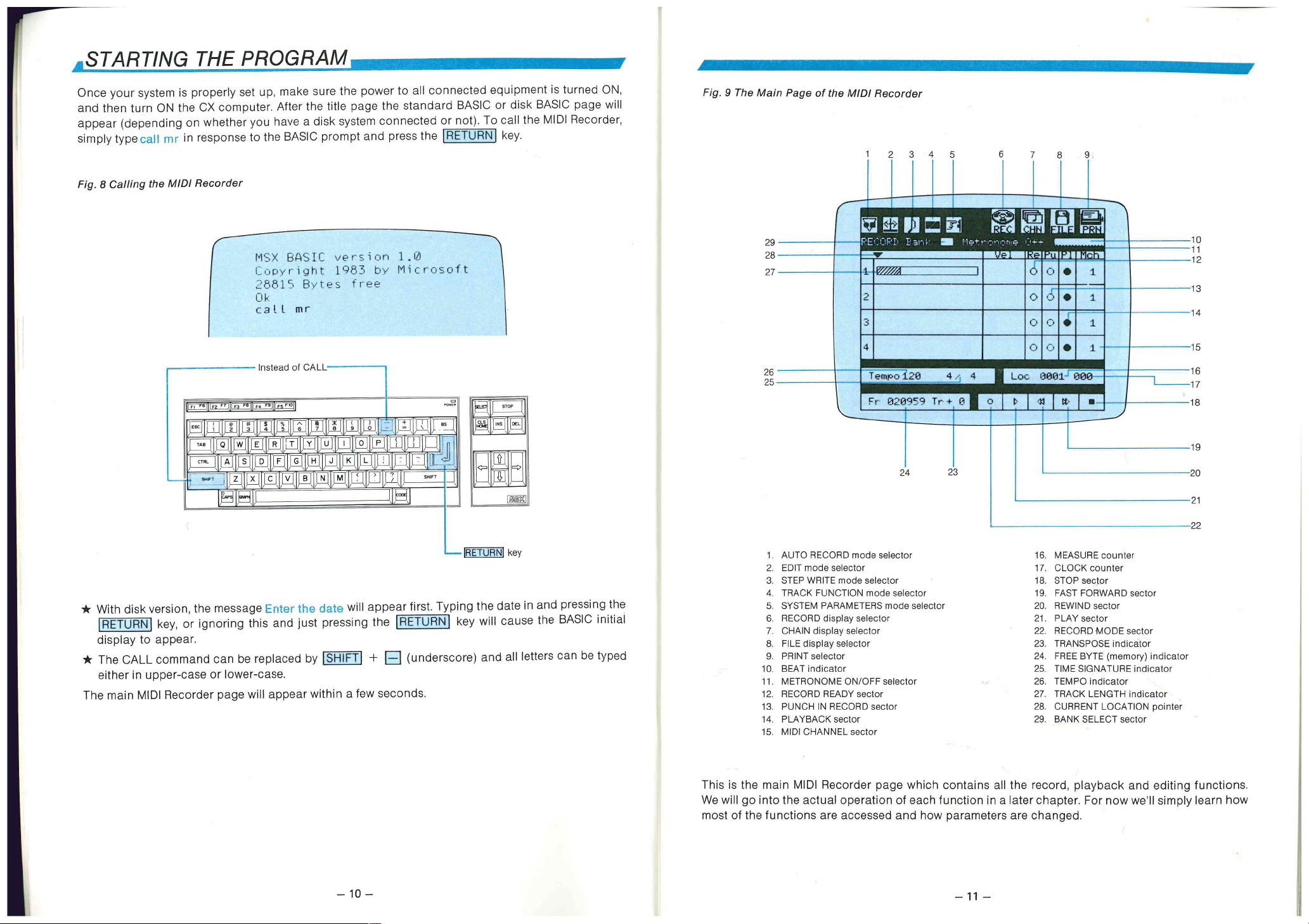
)gram, enter call MR
Mouse
Printer
'MIDI C NNECTIONS
System Example 1: MIDI Recorder + DX7 + Th ree TX7s + RX15
System Example 2: MIDI Recorder + KX88 + TX 4 1 6 -I- RX11
System Example 3: MIDI Recorder + DX21 + SFG-05 Synthesizer Unit
CHAPTER II GETTING STARTED
1
STARTING THE PROGRAM
OVERVIEW OF OPERATION
Using a Mouse
Using the Computer Keyboard
SUMMARY OF OPERATI NS
Keyboard or Mouse General Operations
Keyboard Quick Operations
MIDI CHANNEL ASSIGNMENT
Basic Channel Ass ignm ent
The Multi Mode
10
12
12
13
16
16
18
19
19
20
4
5
5
6
7
9
9
I
i
s a trademark of Microsoft Corporation.
CHAPTER III OPERATING THE MIDI RECORDER
RECORDING AN PLAYBACK
Record Ready
Basic Recording/Playback Procedure
Playback Procedure Further Possibilities
Voice Changes
Auto Record
Punch IN/OUT Record
Multi-track Recording and Playback
The "M" Function
STEP WRITE ECORDING
Note Length Entry
Dotted Notes
Tri p le ts
Rests
Tied Notes
Input Velocity
Gate Length
Note and Chord Entry
Playback
Further Step Write Recording
23
24
24
26
28
29
30
30
31
32
34
34
35
35
35
35
36
36
37
37
Notes in a Chord
e 43
inge 45
45
Change
TIONS 46
on
on 47
Selection
)ction 47
tion
plection
ck
49
47
48
48
48
48
48
METERS 50
53
53
53
54
54
GE 54
Derations
ations
59
59
55
56
57
45
46
46
AGES 59
60
MU1S1K
SVENDBORG
NAS1UM
— 1 —
Cassette Recorder
or
Printer (FN-101)
•-7 Single Cartridge
Adaptor CA-01
it
Floppy Disk
Drive (FD-05)
CX5M
Floppy Disk Drive
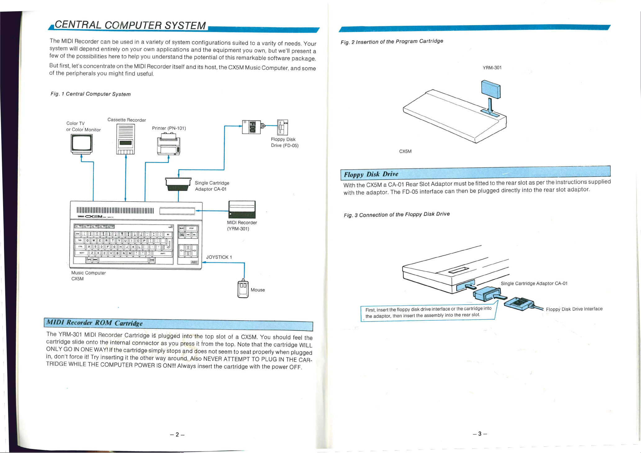
With the CX5M a CA-01 Rear Slot Adaptor must be fitted to the rear slot as per the instructions supplied
with the adaptor. The FID-05 interface can then be plugged directly into the rear slot adaptor.
11111111111111111111111111111111111I I
3M--
JOYSTICK 1
)uter
MIDI Recorder
(YRM-301)
,1 s
Mouse
?OM Cartridge
Recorder Cartridge IS. plugged into the top slot of a CX5K/1. You should feel the
) the internal connector as you press it from the top. Note that the cartridge WILL
/AY! If the cartridge simply stops and does not seem to seat properly when plugged
/ inserting it the other way around. A ls o NEVER ATTEMPT TO PLUG IN THE CAR-
COMPUTER POWER IS ON!!! Always insert the cartridge with the power OFF.
Fig. 3 Connection of the Floppy Disk Drive
Single Cartridge Adaptor CA-01
First, insert the floppy disk drive interface or the cartridge into
the adaptor, then insert the assembly into the rear slot.
r:-- Floppy Disk Drive Interface
11
111111112.7111111 mo&
— 2 —
3
II vary according to the particular model of your CX computer and the type of input
Elo monitor or TV. Refer to your computer manual for video connections.
1
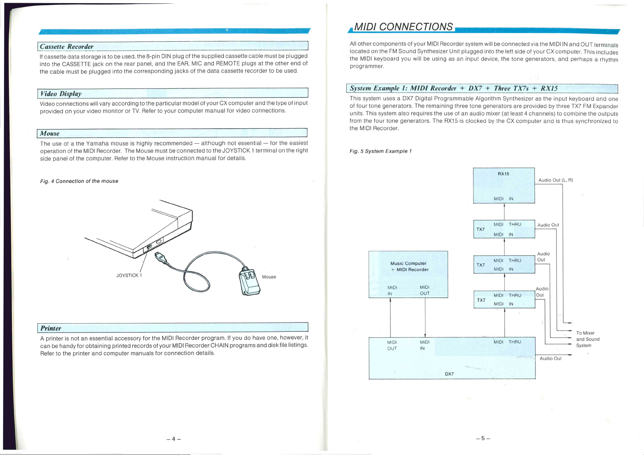
naha mouse is highly recommended — although not essential — for the easiest
Recorder. The Mouse must be connected to the JOYSTICK 1 terminal on the right
riputer. Refer to the Mouse instruction manual for details.
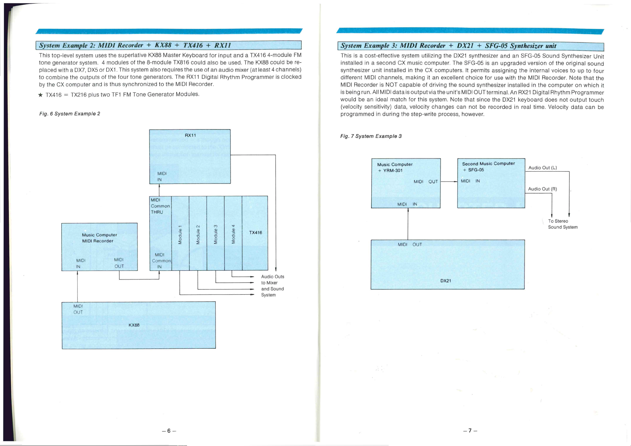
This system uses a DX7 Digital Programmable Alg or it hm Synthesizer as the input keyboard and one
of four tone generators. Th e remaining three tone generators are provided by three TX7 FM Expander
units. Thi s system also requires the use of an audio mixer (at least 4 channels) to comoine the outputs
from the four tone generators. Th e RX15 is clocked by the CX computer and is thus synchronized to
the MIDI Recorder.
Fig. 5 System Example 1
7e mouse
Mouse
sential accessory for the MIDI Recorder program. If you do have one, however, it
aining printed records of your MIDI Recorder CHAIN programs and disk file listings.
nd computer manuals for connection details.
Music Computer
- MIDI Recorder
MIDI MIDI
IN OUT
MIDI
OUT
MIDI
IN
TX7
TX7
TX7
RX15
MIDI IN
MIDI THR U
MIDI IN
MIDI THR U
MIDI IN
MIDI THR U
MIDI IN
MIDI THR U
Audio Out (L, R)
Audio Out
Audio
Out
Audio
Out
To Mixer
and Sound
System
Audio Out
— 4 —
DX7
— 5 —
us two 11-1 1-M lone Uenerator Modules.
e 2
would be an ideal match for this system. Note that since the DX21 keyboard does not output touch
(velocity sensitivity) data, velocity changes can not be recorded in real time. Velocity data can be
programmed in during the step-write process, however.
Fig. 7 System Example 3
Computer
Recorder
MIDI
OUT
KX88
MIDI
Common
THRU
MIDI
Common
IN
—
a)
3
o
o
2
Music Computer
YRM-301
MIDI OUT
MIDI IN
,r
cn
c,i
a,
---
-5
o
o
o
2
2
a,
a,
o
TX416
.5
o
0
Audio Outs
••••••
to Mixer
and Sound
System
MIDI OUT
DX21
Second Music Computer
+ SFG-05
MIDI IN
Audio Out (L)
Audio Out (R)
To Stereo
Sound System
— 6 —
- 7 -
CHAPTER!!
GETTING STARTED
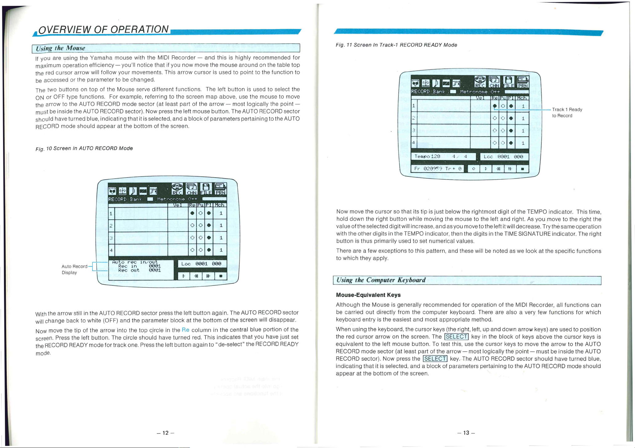
ons. I-or example. referring to the screen map above, use the mouse to move
RECORD mode sector (at least part of the arrow most logically the point —
0 RECORD sector). Now press the left mouse button. T he AUTO RECORD sector
e, indicating that it is selected, and a block of parameters pertaining to the AUTO
I appear at the bottom of the screen.
1-11•71'13:""
EDE
Track 1 Ready
to Record
RECORD Mode
•
vi _t_•ji led • gli r 11;1
RECORD Eari..k.' In Metrs2tioni4 1.-,1+4' • 11.11111.11
.. •- _. _ • .
1
4
i:o.,,c, rec
Oec In
Rec out. 1:1001
le AUTO RECORD sector press the left button again. Th e AUTO RECORD sector
ilte (OFF) and the parameter block at the bottom of the screen will disappear.
le arrow into the top circle in the Re column in the central blue portion of the
utton. The circle should have turned red. T his indicates that you have just set
ode for track one. Press the left button again to "de-select" the RECORD READY
.
wasemaningslanamo
•
ln/OU_ •
lil ll'i CI 1 •
• • 1
.3 • 1
• • .1
0 ri • 1
. _.,.
Loo 0001 0130
-1 1 13' •
ECM
T 1.20 4
Fr 02iTO” Tr ,
Now move the cursor so that its tip is just below the rightmost digit of the TEMPO indicator. This time,
hold down the right button while moving the mouse to the left and right. As you move to the right the
value of the selected digit will increase, and as you move to the left it will decrease. Try the same operation
with the other digits in the TEMPO indicator, then the digits in the TIME SIGNA TURE indicator. T h e right
button is thus primarily used to set numerical values.
There are a few exceptions to this pattern, and these will be noted as we look at the specific functions
to which they apply.
Using the Computer Keyboard
Mouse-Equivalent Keys
Although the Mouse is generally recommended for operation of the MIDI Recorder, all functions can
be carried out directly from the computer keyboard. Th er e are also a very few functions for which
keyboard entry is the easiest and most appropriate method.
When using the keyboard, the cursor keys (the right, left, up and down arrow keys) are used to position
the red cursor arrow on the screen. Th e SELEZT1 key in the block of keys above the cursor keys is
equivalent to the left mouse button. To test this. use the cursor keys to move the arrow to the AUTO
RECORD mode sector (at least part of the arrow most logically the point must be inside the AUTO
RECORD sector). Now press the I SELECTI key. The AUTO RECORD sector should have turned blue,
indicating that it is selected, and a block of parameters pertaining to the AUTO RECORD mode should
appear at the bottom of the screen.
L(..: 0001 000
11111111111111111111:11
— 12 —
— 13 —
,ase its value. Try the same operation with the other digits in the TEMPO indicator,
- I- -
FIME SIGNATURE indicator.
.9nt Keys
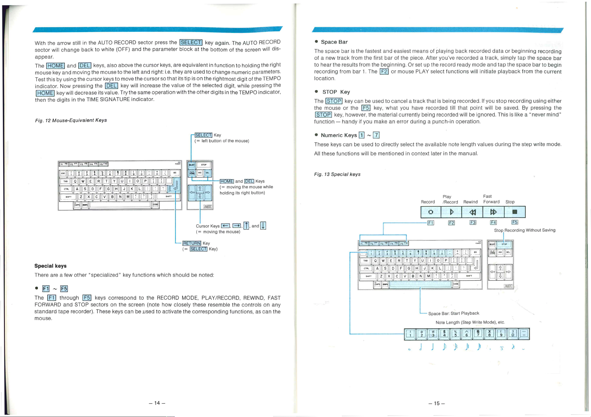
* STOP Key
The 'STOP key can be used to cancel a track that is being recorded. If you stop recording using either
the mouse or the I F5 key, what you have recorded till that point will be saved. By pressing the
STOP
function handy if you make an error during a punch-in operation.
key, however, the material currently being recorded will be ignored. Thi s is like a "never mind"
'SELECT
= left button of the mouse)
(MIMI
ITI
IT Eri Y
LEJ
)1,11, ,
r-
"specialized" key functions which should be noted:
keys correspond to the RECORD MODE, PLAY/RECORD, REWIND. FAST
sectors on the screen (note how closely these resemble the controls on any
?r). Th ese keys can be _used to activate the corresponding functions, as can the
aLx
u ,
761
H,JLLItJ
(
•
-1 1 , ,J--
•,[1m or
E
) '3- L_ --,
,
,R,
,
1 ,
7
N
1RETURNJ
Cursor Keys
(= moving the mouse)
'SELECT'
Key
Kl\---A-E-1 and 'DEL' Keys
(= moving the mouse while
F>
holding its right button)
I --*1
<— I
Key
Key)
, and
to Numeric Keys 1 —
These keys can be used to directly select the available note length values during the step write mode.
All these functions will be mentioned in context later in the manual.
Fig. 13 Special keys
7
, ,---- 01 141 17OR if 1.1 17i- '''
.I.,11-q
.I.,11-q
qt_J1,—, lizi Lti
— rE-91 TAT E — IR -
J ''' I H
—
s"1" 1,,_X .„[C_IA_JI B1 ,
_
Record /Record Rewind Forward Stop
— T- 1 fr2- M
Play Fast
41
—g,
1)o ,
EF,1 1
Stop Recording Without Saving
11 tfl ti:
j_l_f P ,EJ:
114 [1:1
, „I I 13171t su'r
_ . ,
_ . ,
4E11
4E11
Space Bar: Start Playback
Note Length (Step Write Mode , etc.
@2
WI
L1J6
f,
f,
le
c=;>
:
I-T91
IF51
rn
Ol
Li
14
. J J ) ) -3- -
— 15 —
 Loading...