

Page 1

2002
YFZ350
(
P
)
3GG-AE2
SUPPLEMENTARY
SERVICE MANUAL
Page 2

Page 3
FOREWORD
This Supplementary Service Manual has been prepared to introduce new service and new data for
the YFZ350(P) 2002. For complete information on service procedures, it is necessary to use this
Supplementary Service Manual together with the following manual.
YFZ350T SERVICE MANUAL: 2GU-28197-20
YFZ350 SUPPLEMENTARY SERVICE MANUAL: 3GG-28197-20
YFZ350 SUPPLEMENTARY SERVICE MANUAL: 3GG-28197-21
YFZ350(J)/(K) ’97/’98 SUPPLEMENTARY SERVICE MANUAL: 3GG-AE1
YFZ350(P) 2002
SUPPLEMENTARY
SERVICE MANUAL
2001 by Yamaha Motor Co., Ltd.
First Edition, May 2001
All rights reserved.
Any reproduction or unauthorized use
without the written permission of
Yamaha Motor Co., Ltd.
is expressly prohibited.
Page 4
EB001000
NOTICE
This manual was produced by the Yamaha Motor Company primarily for use by Yamaha dealers
and their qualified mechanics. It is not possible to include all the knowledge of a mechanic in one
manual, so it is assumed that anyone who uses this book to perform maintenance and repairs on
Yamaha machine has a basic understanding of the mechanical ideas and the procedures of
machine repair. Repairs attempted by anyone without this knowledge are likely to render the
machine unsafe and unfit for use.
Yamaha Motor Company, Ltd. is continually striving to improve all its models. Modifications and significant changes in specifications or procedures will be forwarded to all authorized Yamaha dealers
and will appear in future editions of this manual where applicable.
OTE:
Designs and specifications are subject to change without notice.
IMPORTANT INFORMATION
Particularly important information is distinguished in this manual by the following notations.
The Safety Alert Symbol means ATTENTION! BECOME ALERT! YOUR
SAFETY IS INVOLVED!
WARNING
CAUTION:
NOTE:
Failure to follow WARNING instructions could result in severe injury or death
to the machine operator, a bystander or a person inspecting or repairing the
machine.
A CAUTION indicates special precautions that must be taken to avoid damage to the machine.
A NOTE provides key information to make procedures easier or clearer.
Page 5
HOW TO USE THIS MANUAL
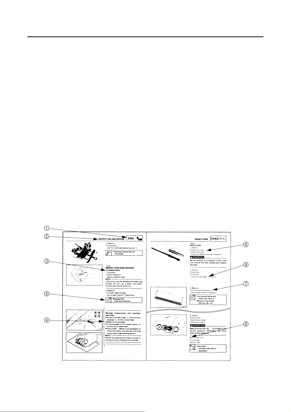
CONSTRUCTION OF THIS MANUAL
This manual consists of chapters for the main categories of subjects. (See “Illustrated symbols”)
1st title 1: This is a chapter with its symbol on the upper right of each page.
2nd title 2: This title appears on the upper of each page on the left of the chapter sym-
bol. (For the chapter “Periodic inspection and adjustment” the 3rd title
appears.)
3rd title 3: This is a final title.
MANUAL FORMAT
All of the procedures in this manual are organized in a sequential, step-by-step format. The information has been compiled to provide the mechanic with an easy to read, handy reference that contains
comprehensive explanations of all disassembly, repair, assembly, and inspections.
A set of particularly important procedure 4 is placed between a line of asterisks “
dure preceded by “
●
”.
IMPORTANT FEATURES
●
Data and a special tool are framed in a box preceded by a relevant symbol 5.
●
An encircled numeral 6 indicates a part name, and an encircled alphabetical letter data or an
alignment mark 7, the others being indicated by an alphabetical letter in a box 8.
●
A condition of a faulty component will precede an arrow symbol 9 and the course of action will follow it.
*
” with each proce-
EXPLODED DIAGRAM
Each chapter provides exploded diagrams before each disassembly section for ease in identifying
correct disassembly and assembly procedures.
Page 6
12
GEN
INFO
34
SPEC
CHK
ADJ
56
CARB
78
ENG
COOL
EB003000
ILLUSTRATED SYMBOLS
Illustrated symbols 1 to 9 are printed on the
top right of each page and indicate the subject
of each chapter.
1 General information
2 Specifications
3 Periodic checks and adjustments
4 Engine
5 Carburetion
6 Cooling system
7 Chassis
8 Electrical
9 Troubleshooting
CHAS
90
ELEC
– +
TRBL
SHTG
AB
CD
T
.
R
.
EF
GHI
Illustrated symbols 0 to F are used to identify
the specifications appearing in the text.
0 Filling fluid
A Lubricant
B Special tool
C Torque
D Wear limit, clearance
E Engine speed
Ω, V, A
F
Illustrated symbols G to M in the exploded
diagrams indicate the types of lubricants and
lubrication points.
LS
G
M
M
S
E
J
NO
KLM
B
New
LT
G Apply engine oil
H Apply gear oil
I Apply molybdenum disulfide oil
J Apply wheel bearing grease
K Apply lightweight lithium soap base grease
L Apply molybdenum disulfide grease
M Apply silicon grease
Illustrated symbols N to O in the exploded
diagrams indicate where to apply a locking
agent N and when to install a new part O.
N Apply the locking agent (LOCTITE
O Replace
)
Page 7

CONTENTS
SPECIFICATIONS
GENERAL SPECIFICATIONS ...................................................................1
MAINTENANCE SPECIFICATIONS ..........................................................2
ENGINE .................................................................................................2
CHASSIS ...............................................................................................3
ELECTRICAL.........................................................................................4
CABLE ROUTING ......................................................................................5
PERIODIC CHECKS AND ADJUSTMENTS
INTRODUCTION......................................................................................12
PERIODIC MAINTENANCE/LUBRICATION INTERVALS.......................12
CHASSIS..................................................................................................14
ADJUSTING THE FRONT BRAKE......................................................14
ADJUSTING THE REAR BRAKE LIGHT SWITCH..............................14
ADJUSTING THE REAR SHOCK ABSORBER...................................15
ELECTRICAL
CHECKING THE SWITCH .......................................................................18
CHECKING THE SWITCH...................................................................18
CHECKING A SWITCH SHOWN IN THE MANUAL ............................18
SIGNAL SYSTEM ....................................................................................19
CIRCUIT DIAGRAM.............................................................................19
CHECKING THE SIGNAL SYSTEM....................................................20
.............................................................................................1
...................................................12
..................................................................................................18
YFZ350(P) 2002 WIRING DIAGRAM
Page 8

Page 9
GENERAL SPECIFICATIONS
SPEC
SPECIFICATIONS
GENERAL SPECIFICATIONS
Model YFZ350(P) 2002
Model code number 5FKF: (CDN)
5FKG: (Europe and Oceania)
Lubrication system: Premix
Premix ratio YAMALUBE “R” 24 : 1
CASTROL R30 20 : 1
CASTROL A545 20 : 1
CASTROL A747 20 : 1
Transmission oil YAMALUBE 4 or SAE 10W30 type SE motor oil
Spark plug:
Type BR8ES
Manufacturer NGK
Spark plug gap 0.7 ~ 0.8 mm (0.028 ~ 0.032 in)
Tire:
Type Tubeless
Size: Front AT21 × 7-10
Rear AT22 × 10-9
Manufacturer/type: Front DUNLOP/KT851A
Rear DUNLOP/KT877
Wear Limit 3 mm (0.12 in)
Shock absorber:
Front Coil spring/oil damper
Rear Coil spring/gas-oil damper
Wheel travel:
Front 230 mm (9.06 in)
Rear 220 mm (8.66 in)
Electrical:
Ignition system C.D.I.
Generator system C.D.I. magneto
Headlight type Bulb type
Headlight bulb type Krypton bulb
Bulb voltage/watage × quantity:
Headlight 12 V 30 W/30 W × 2
Tail/brake light 12 V 5 W/21 W × 1
– 1 –
Page 10
MAINTENANCE SPECIFICATIONS
MAINTENANCE SPECIFICATIONS
ENGINE
Model YFZ350(P) 2002
Carburetor:
I.D. mark 2GU 01
Fuel level (F.L.)
(With special tool) 0.5 ~ 1.5 mm (0.020 ~ 0.059 in)
Float height (F.H.) 20.5 ~ 21.5 mm (0.81 ~ 0.85 in)
Main jet (M.J.) #200
Main air jet (M.A.J.) ø1.6
Jet needle (J.N.) 5N7-3
Needle jet (N.J.) O-8
Cutaway (C.A.) 2.0
Pilot outlet (P.O.) ø0.6
Pilot jet (P.J.) #25
Bypass 1 (B.P.1.) 1.4
Air screw (A.S.) 2.0 turns out
Valve seat size (V.S.) 2.8
Starter jet (G.S.) ø1.4
Engine idle speed 1,450 ~ 1,550 r/min
Cooling system:
Radiator core size:
Width 210 mm (8.27 in)
Height 350 mm (13.8 in)
Thickness 32 mm (1.26 in)
Radiator cap opening pressure 95 ~ 125 kPa (0.95 ~ 1.25 kg/cm
13.8 ~ 18.1 psi)
Reservoir tank
Capacity 0.28 L (0.246 Imp qt, 0.296 US qt)
From low to full level 0.07 L (0.06 Imp qt, 0.07 US qt)
Water pump
Type Single-suction centrifugal pump
Reduction ratio 32/20 (1,600)
SPEC
2
,
– 2 –
Page 11

MAINTENANCE SPECIFICATIONS
CHASSIS
Model YFZ350(P) 2002
Rear disc brake:
Type Single
Disc outside diameter × thickness 220.0 × 3.6 mm (8.66 × 0.142 in)
Pad thickness Inner 4.5 mm (0.18 in)
<Limit> <1 mm (0.039 in)>
Pad thickness Outer 4.5 mm (0.18 in)
<Limit> <1 mm (0.039 in)>
Master cylinder inside diameter 12.7 mm (0.50 in)
Caliper cylinder inside diameter 33.96 mm (1.34 in)
Brake fluid type DOT #4
Brake lever and brake pedal:
Brake lever free play 0 mm (0 in) at lever end
Brake pedal position 10 mm (0.4 in)
Brake pedal free play 8 mm (0.3 in)
Throttle lever free play 4 ~ 6 mm (0.16 ~ 0.24 in)
SPEC
– 3 –
Page 12

MAINTENANCE SPECIFICATIONS
ELECTRICAL
Model YFZ350(P) 2002
Voltage 12 V
Ignition system:
Ignition timing (B.T.D.C.) 17 °/1,200 r/min
Advanced timing (B.T.D.C.) 10 °/9,500 r/min
Advancer type Digital type
30
20
(B.T.D.C.)
10
Ignition timing
0 35791246810
Engine speed (× 103 r/min)
SPEC
C.D.I.:
Magneto model/manufacture TVCF57/DENSO
Pickup coil resistance (color) 94 ~ 140 Ω at 20 °C (68 °F)
(White/Red–White/Green)
Charging coil resistance (color) 13.7 ~ 20.5 Ω at 20 °C (68 °F) (Green–Red)
C.D.I. unit model/manufacture QAC68/DENSO
Spark plug cap:
Type Resin type
Resistance 5 kΩ
F.W.magneto:
Model/manufacturer TVCF57/DENSO
Lighting voltage 13.5 ~ 14.1 V/5,000 r/min
Lighting coil resistance (color) 0.26 ~ 0.38 Ω at 20 °C (68 °F)
(Yellow–Black)
20
15
10
5
Lighting voltage (V)
0 35791246810
Engine speed (× 103 r/min)
– 4 –
Page 13

CABLE ROUTING
1 Throttle switch lead
2 Front brake light switch lead
3 Throttle cable
4 Fuel tank breather hose
5 Band
6 Handle switch
7 Park switch
8 Parking brake cable
9 Clutch cable
0 Front brake hose
A Main switch lead
B Handle switch lead
C Park switch lead
D Breather hose
E Front brake pipe
F Headlight lead
G Radiator hose
CABLE ROUTING
È Pass the hose through the han-
dle protector hole.
É Clamp the hoses.
SPEC
– 5 –
Page 14

CABLE ROUTING
SPEC
1 Main switch
2 Throttle switch lead
3 Front brake light switch lead
4 Wire harness
5 Fuel hose
6 Crankcase breather hose
7 Carburetor over flow hose
8 Radiator hose
9 Park switch lead
0 Handle switch lead
È Pass the wire harness through the guide. Align
the marking tape in front of the guide.
É Pass the hose through the guide.
Ê Pass the hose through the guide.
– 6 –
Page 15

1 CDI unit lead
2 Tail/brake light lead
È Clamp the CDI unit lead and Tail/Brake light lead.
CABLE ROUTING
SPEC
– 7 –
Page 16

CABLE ROUTING
SPEC
1 Carburetor switch lead
2 Throttle cable
3 Band
4 Clutch cable
5 Parking brake cable
6 Breather hose
7 Front brake light switch lead
8 Wire harness
È Pass the lead above the hoses and cables.
É Pass the cable through the guide.
Ê Route the hose behind the clutch and parking
cable. Pass the hose between both carburetor
joints.
Ë Pass the hoses inside the wire harness.
– 8 –
Page 17

CABLE ROUTING
SPEC
1 Clamp
2 Band
3 Rear brake light switch
4 CDI magneto lead
5 Cable guide
6 Rear brake light switch wire
7 Wire guide
8 Rear brake hose
È Pass the wire harness and hoses through the
guide on the air cleaner.
É Route the cable behind the rear brake hose.
– 9 –
Page 18

CABLE ROUTING
SPEC
1 Headlight
2 Ignition coil
3 Wire harness
4 Carburetor switch lead
5 T.O.R.S. control unit
È Ignition coil lead (Orange)
É Ignition coil lead (Black)
– 10 –
Page 19

1 Reserver tank
2 Voltage regulator
3 Body earth
4 Tail/brake light lead
5 Clamp
6 CDI unit
CABLE ROUTING
SPEC
– 11 –
Page 20

INTRODUCTION/
PERIODIC MAINTENANCE/LUBRICATION INTERVALS
EB300000
CHK
ADJ
PERIODIC CHECKS AND ADJUSTMENTS
INTRODUCTION
This chapter includes all information necessary to perform recommended inspections and adjustments. These preventive maintenance procedures, if followed, will ensure more reliable vehicle
operation and a longer service life. The need for costly overhaul work will be greatly reduced. This
information applies to vehicles already in service as well as to new vehicles that are being prepared
for sale. All service technicians should be familiar with this entire chapter.
EB301000
PERIODIC MAINTENANCE/LUBRICATION INTERVALS
ITEM ROUTINE
Transmission • Replace oil.
Cooling system
Spark plug
Air filter
*Carburetor
* Crankcase
breather system
* Exhaust system
* Fuel line
Throttle operation • Inspect and adjust free play if necessary.
* Front and rear
brake operation
* Front and rear
brake pads
*Clutch
Drive chain
* Drive chain guard
and rollers
* Steering system • Inspect free play, clean and lubricate.
* Front and rear
suspension
Tires, wheels
Throttle, control
cable
Outside nuts and
bolts
Frame • Clean and inspect.
Lighting equipment • Inspect.
• Check coolant leakage.
• Repair if necessary.
• Replace coolant every 24 months.
• Check condition.
• Adjust gap and clean.
• Replace if necessary.
• Clean.
• Replace if necessary.
• Check idle speed/starter operation.
• Adjust if necessary.
• Check breather hose for cracks or damage.
• Replace if necessary.
• Check for leakage.
• Retighten if necessary.
• Replace gasket(s) if necessary.
• Check fuel hose for cracks or damage.
• Replace if necessary.
• Check operation/fluid leakage/See NOTE Page 13.
• Correct if necessary.
• Check pad wear.
• Replace if necessary.
• Inspect free play and operation.
• Replace if necessary.
• Check chain slack/alignment.
• Adjust if necessary.
• Clean and lube.
• Replace if necessary.
• Check wear and replace if necessary.
• Inspect and lubricate.**
• Inspect air pressure, wheel runout, and tire wear.
• *Inspect bearings.
• *Replace bearings if necessary.
• Check routing and connection.
• Lubricate.
• Retighten.
INITIAL EVERY
1
month3months6months6months1year
Every 20 ~ 40 hours.
(More often in wet or dusty areas)
* It is recommended that these items be serviced by a Yamaha dealer.
** Lithium-soap-based grease
– 12 –
Page 21

CHK
PERIODIC MAINTENANCE/LUBRICATION INTERVALS
NOTE:
Recommended brake fluid: DOT 4
●
Brake fluid replacement:
●
1.When disassembling the master cylinder or caliper, replace the brake fluid. Normally check the
brake fluid level and add fluid as required.
2.On the inner parts of the master cylinder and caliper, replace the oil seals every two years.
3.Replace the brake hoses every four years, or if cracked or damaged.
ADJ
– 13 –
Page 22

ADJUSTING THE FRONT BRAKE/
ADJUSTING THE REAR BRAKE LIGHT SWITCH
CHASSIS
ADJUSTING THE FRONT BRAKE
1.Check:
Brake lever free play a
●
Out of specification → Bleed the front brake
system.
Refer to “AIR BLEEDING” in CHAPTER 6.
(Manual No.: 2GU-28197-20)
Brake lever free play (at brake
lever end):
0 mm (0 in)
ADJUSTING THE REAR BRAKE LIGHT
SWITCH
NOTE:
The rear brake light switch is operated by
movement of the brake pedal.
The rear brake light switch is properly adjusted
when the brake light comes on just before the
braking effect starts.
CHK
ADJ
1.Check:
Rear brake light operation timing
●
Incorrect → Adjust.
2.Adjust:
Rear brake light operation timing
●
***********************************************
Hold the main body 1 of the rear brake light
●
switch so that it does not rotate and turn the
adjusting nut 2 in direction a or b until the
rear brake light comes on at the proper time.
Direction a
Direction b
Brake light comes on
sooner.
Brake light comes on
later.
***********************************************
– 14 –
Page 23

ADJUSTING THE REAR SHOCK ABSORBER
ADJUSTING THE REAR SHOCK
ABSORBER
1.Adjust:
Spring preload
●
***********************************************
Adjustment steps:
Elevate the rear wheels by placing a suitable
●
stand under the frame.
Loosen the locknut 1.
●
Turn the adjusting ring 2 in direction a or
●
b.
Spring preload is
Direction a
Direction b
increased (suspension
is harder).
Spring preload is
decreased (suspension
is softer).
CHK
ADJ
Adjusting length c:
Standard: 220.5 mm (8.68 in)
Minimum: 213.5 mm (8.41 in)
Maximum: 228.5 mm (9.00 in)
NOTE:
Be sure to remove all dirt and mud from
●
around the locknut and adjusting ring before
adjustment.
The length of the spring (installed) changes
●
1.5 mm (0.06 in) per turn of the adjuster.
CAUTION:
Never attempt to turn the adjusting ring
beyond the maximum or minimum setting.
Tighten the locknut 1.
●
Locknut:
T
NOTE:
Always tighten the locknut against the adjusting ring, then torque it to specification.
54 Nm (5.4 m • kg, 39 ft • lb)
.
R
.
***********************************************
– 15 –
Page 24

ADJUSTING THE REAR SHOCK ABSORBER
2.Adjust:
Rebound damping force
●
***********************************************
Adjustment steps:
Turn the adjuster 1 in direction a or b.
●
CHK
ADJ
Direction a
Direction b
From the fully turned-in position:
Standard: 13 clicks out
Minimum: 20 clicks out
Maximum: 3 clicks out
Rebound damping force
is increased.
Rebound damping force
is decreased.
CAUTION:
Do not force the adjuster past the minimum
or maximum extent of adjustment. The
adjuster may be damaged.
***********************************************
3.Adjust:
Compression damping force
●
***********************************************
Adjustment steps:
Turn the adjuster 1 in direction a or b.
●
Direction a
Direction b
From the fully turned-out position:
Standard: 11 clicks in
Minimum: 1 click in
Maximum: 15 clicks in
– 16 –
Compression damping
force is increased.
Compression damping
force is decreased.
Page 25

ADJUSTING THE REAR SHOCK ABSORBER
CAUTION:
Do not forc the adjuster past the minimum
or maximum extent of adjustment. The
adjuster may be damaged.
***********************************************
CHK
ADJ
– 17 –
Page 26

CHECKING THE SWITCH
ELECTRICAL
CHECKING THE SWITCH
CHECKING THE SWITCH
Use a pocket tester to check the terminals for
continuity. If the continuity is faulty at any
point, replace the switch.
Pocket tester:
P/N. YU-03112, 90890-03112
OTE:
Set the pocket tester to “0” before starting
●
the test.
The pocket tester should be set to the “Ω × 1”
●
range when testing the switch for continuity.
Turn the switch on and off a few times when
●
checking it.
ELEC
– +
CHECKING A SWITCH SHOWN IN THE
MANUAL
The terminal connections for switches (main
switch, handlebar switch, engine stop switch,
light switch, etc.) are shown in a chart similar
to the one on the left.
This chart shows the switch positions in the
column and the switch lead colors in the top
row.
For each switch position, “” indicates
the terminals with continuity.
The example chart shows that:
There is continuity between the “Black and
1
Red/Brown” leads when the switch is set to
“ON”.
– 18 –
Page 27

EB806000
SIGNAL SYSTEM
CIRCUIT DIAGRAM
1 CDI magneto
2 Voltage regulator
E Tail/brake light
F Rear brake light switch
G Front brake light switch
SIGNAL SYSTEM
B
B/WB/Y
BB/Y
8
B/YB
(BLACK)
(BLACK)
B
B
Y/BB/W
7
B
B/Y
B/Y
ELEC
– +
B/W
B
R/B
G/YO
W/RG
W/GR
Y/BB
BY/B
B
(GRAY)
(GRAY)
6
B/W
B/Y
Y/BB
9
Y/BB/Y
Y/B
Y/B
(GRAY)
9
(GRAY)
5
R/BB
B
O
O
B
R/B
OG/Y
B/W
3
RW/G
GW/R
R R/B
W/R
W/G
B
B/W
G/Y
G
G/Y
4
B
BB
BG/Y
BR/B
B
ON
0
OFF
B/W R/B
OFF
RUN
AB
Y/R
HI
LO
OFF
B
L G Y
D
YG
G Y
G Y
D
YG
Y L
B
B
GY
B
B
B
B
GY
B
E
L
R
G
W/R
W/G
Y/R
W/GR
RW/G
B
W/RG
GW/R
1
B
2
C
Y
G
Y/RL
B/WB
Y
G
LY/R
BB/W
YY/R
(BLACK)
F
BB
(BLACK)
BB
YY/R
Y
Y
(BLACK)
(BLACK)
Y/R
Y/R
G
– 19 –
Page 28

CHECKING THE SIGNAL SYSTEM
1.If the tail/brake light fails to come on:
SIGNAL SYSTEM
ELEC
– +
1.Bulb and bulb socket
Check the bulb and bulb socket for continu-
●
ity.
CONTINUITY
2.Brake light switches
Refer to “CHECKING THE SWITCH”.
CONTINUITY
3.Voltage
Connect the tachometer to the spark plug
●
lead.
Connect the pocket tester (DC 20V) to the
●
bulb socket connector.
Tester (+) lead → Yellow terminal 1
Tester (–) lead → Black terminal 2
NO CONTINUITY
Replace the bulb and/or bulb socket.
NO CONTINUITY
Replace the brake switch.
Start the engine and accelerate to about
●
5,000 r/min.
CAUTION:
Do not run the engine in neutral above
8,000 r/min for more than 5 seconds.
Lighting voltage:
13.5 ~ 14.1 V/5,000 r/min
OUT OF
SPECIFICATION
*
MEETS SPECIFICATION
The lighting circuit is not faulty.
– 20 –
Page 29

*
4.Lighting coil resistance
Disconnect the CDI magneto leads (Yel-
●
low/Red and Black).
Connect the pocket tester (Ω × 1) to the
●
lighting coil leads.
Tester (+) lead → Yellow 1 lead
Tester (–) lead → Black 2 lead
SIGNAL SYSTEM
OUT OF SPECIFICATION
ELEC
– +
Measure the lighting coil resistance.
●
Lighting coil resistance:
0.26 ~ 0.38 Ω at 20 °C (68 °F)
MEETS
SPECIFICATION
5.Wiring connections
Check the connections of the entire lighting
●
system.
Refer to “CIRCUIT DIAGRAM”.
CORRECT
Replace the voltage regulator.
Replace the stator assembly.
POOR CONNECTION
Properly connect the lighting system.
– 21 –
Page 30

Page 31

YFZ350(P) 2002 WIRING DIAGRAM
W/R
W/G
G
R
L
B
BG/Y
RW/G
GW/R
W/GR
W/RG
2
1
B
Y/R
W/GR
G/YO
W/RG
RW/G
GW/R
W/R
W/G
R R/B
G
R/B
B/W
B
OG/Y
R/B
B/W
B
3
B
G/Y
B/W
G/Y
4
BB
B
1 CDI magneto
2 Voltage regulator
3 CDI unit
4 Park switch
5 Ignition coil
6 Spark plug
O
O
B
6
5
7 T.O.R.S. control unit
8 Throttle switch
9 Carburetor switch
0 Main switch
A Engine stop switch
B Lights switch
C Handle switch (left)
D Headlight
E Tail/brake light
F Rear brake light switch
G Front brake light switch
B/W
Y/BB/W
B/WB/Y
B
B
7
B/Y
B
YY/R
(BLACK)
G
BB
(BLACK)
Y/R
Y
LY/R
BB/WYG
Y/R
(BLACK)
Y
C
Y/RL
B/WB
F
BB
Y
G
YY/R
(BLACK)
OFF
LO
HI
Y/R
L G Y
Y L
E
B
D
YG
B
GY
B
G Y
B
B/W R/B
AB
RUN
OFF
B
G Y
D
YG
B
GY
B
B
OFF
ON
BR/B
0
B
COLOR CODE
B ............ Black
G............Green
L.............Blue
O............Orange
R............ Red
Y ............ Yellow
R/BB
Y/BB/Y
(GRAY)
BY/B
(GRAY)
9
Y/BB
(GRAY)
9
Y/BB
(GRAY)
B/Y
B/Y
8
B/YB
(BLACK)
Y/B
B
Y/B
B
B/W........Black/White
B/Y.........Black/Yellow
G/Y ........Green/Yellow
R/B.........Red/Black
W/G .......White/Green
W/R........White/Red
BB/Y
(BLACK)
Y/B .........Yellow/Black
Y/R.........Yellow/Red
 Loading...