

Page 1

READ THIS MANUAL CAREFULLY!
It contains important safety information.
LIRE ATTENTIVEMENT CE MANUEL!
Il comprend d’importantes informations de sécurité.
¡LEA ESTE MANUAL ATENTAMENTE!
Contiene indicaciones importantes acerca de la seguridad.
OWNER’S MANUAL
MANUEL DU PROPRIÉTAIRE
MANUAL DEL PROPIETARIO
YFM35FGB
YFM350FAB
1NS-F8199-60
Page 2

PRINTED IN USA
2011.08-0.5×1 CR
(E,F,S)
Page 3

READ THIS MANUAL CAREFULLY!
It contains important safety information.
OWNER’S MANUAL
YFM35FGB
YFM350FAB
1NS-F8199-60-E0
Page 4

EBU17135
Read this manual carefully before operating this vehicle. This manual should stay with this ve-
hicle if it is sold.
EC Declaration of Conformity
conforming to Directive 2006/42/EC
We, YAMAHA MOTOR CO., LTD. 2500 Shingai, Iwata, Japan,
declare in sole responsibility, that the product
YFM350FWA (YFM35FG) (5Y4AH13W0B0514767–)
(Make, model)
to which this declaration applies, conforms to the essential health
and safety requirements of Directive 2006/42/EC
(If applicable)
and to the other relevant Directives of EEC
(Title and/or number and date of issue of the other Directives of EEC)
(If applicable)
To effect correct application of the essential health and safety requirements
stated in the Directives of EEC, the following-standards and/or technical
specifications were consulted:
(Title and/or number and date of issue of standards and/or specifications)
Manufacturer
YAMAHA MOTOR MANUFACTURING CORPORATION OF AMERICA
1000 GA Highway 34 East, Newnan, Georgia 30265-1320, U.S.A.
Authorized Representative
YAMAHA MOTOR EUROPE N.V.
Koolhovenlaan 101, 1119 NC Schiphol-Rijk, The Netherlands
2004/108/EC
ANSI/SVIA 1-2010
Signature
General Manager
RV Engineering Division
Recreational Vehicle Business Unit
Motorcycle Business Operations
YAMAHA MOTOR CO., LTD.
Date of Issue
Shinya Shimada
20 April, 2011
Page 5

EBU17170
INTRODUCTION
EBU17292
Congratulations on your purchase of the Yamaha YFM35FGB/YFM350FAB. This ATV represents the result
of many years of Yamaha experience in the production of fine sporting, touring, and pacesetting racing machines. With th e p ur c ha se o f this Yamaha, you can now apprecia te t he hi gh de gree of craftsma nshi p a nd
reliability th at hav e made Y am ah a a le ad er in th e se f iel ds .
This manual w ill provid e you wit h a good b asic under standing of the f eatures an d operat ion of this ATV.
This manual includes important safety information. It provides information about special techniques and skills n ece ssar y to ride the ATV . It a ls o i n cl u des ba s ic m ai nte nance and inspection pr o c e-
dures. If you h ave any ques tions rega rding the ope ration or maintenance of your AT V, please c onsult a
Yamaha dealer .
AN IMPORTANT SAFETY MESSAGE:
● Read this manual completely before operating your ATV. Make sure you understand all instructions.
● Pay close attenti on to the wa rn ing an d no t ice lab el s on the AT V.
● This ATV should not be ridden by anyone under 16 years of age.
Page 6
EBU17330
IMPORTANT MANUAL INFORMATION
EBU17342
FAILURE TO FOLLOW THE WARNINGS CONTAINED IN THIS MANUAL CAN RESULT IN SERIOUS INJURY OR DEATH.
Particularly importa nt info rma t ion is di st in gu ished in t his manua l by the fo ll ow ing no t atio ns:
This is the safety alert symbol. It is used to alert you to potential personal injury hazards. Obey all safety messages that follow this symbol to avoid possible injury or death.
WARNING
NOTICE
TIP
A WARNING indicates a hazardous situation which, if not avoided,
could result in death or serious injury.
A NOTICE indicates special precautions that must be taken to avoid
damage to the vehicle or other property.
A TIP provides key information to make procedures easier or clearer.
* Product and speci fi cat io ns are su bj ect to cha ng e wit ho ut no ti ce .
Page 7

EBU17350
IMPORTANT NOTICE
EBU17372
This ATV is designed and manufactured for use on unpaved surfaces only. It is unsafe to operate this ATV
on any paved surface, paved street, paved road or motorway.
Please check your lo cal ri di ng laws an d re gu lations before operating this ATV.
EBU17410
YFM35FGB/YFM350FAB
OWNER’S MANUAL
©2011 by Yamaha Motor Co., Ltd.
1st edition, July 2011
All rights reserved.
Any reprinting or unauthorized use
without the written permission of
Yamaha Motor Co., Ltd.
is expressly prohibited.
Printed in U.S.A.
Page 8

EBU17420
TABLE OF CONTENTS
LOCATION OF THE WARNING AND
SPECIFICATION LABELS ............................1-1
SAFETY INFORMATION ..............................2-1
DESCRIPTION ..................... .........................3-1
Left view......................................................3-1
Right view....................................................3-1
Controls and instruments............................3-2
INSTRUMENT AND CONTROL
FUNCTIONS ..................................................4-1
Main switch ................................................4-1
Indicator lights and warning light ................4-2
Speedometer ............... ................... ............4-3
Handlebar switches .................................... 4-4
Throttle lever ..............................................4-5
Speed limiter ..............................................4-6
Front brake lever ........................................4-7
Brake pedal and rear brake lever ...............4-7
Parking brake .............................................4-8
Drive select lever ........................................4-9
Fuel tank cap ..............................................4-9
Fuel .......................................................... 4-10
Fuel cock ..................................................4-11
Starter (choke) ..........................................4-13
Seat ..........................................................4-13
Storage compartment ...............................4-14
Front carrier ..............................................4-15
Rear carrier ........................... ....... ...... ....... 4- 15
Adjusting the front shock abso rb er
assemblies ............. .................................4-16
Adjusting the rear shock abs orber
assembly ................ ....... ...... ....... ...... ....... 4-17
PRE-OPERATION CHECKS ..........................5-1
Fuel .......................... ...................................5-3
Engine oil ....................................................5-3
Final gear oil ................... ...... ....... ...... .........5-3
Differential gear oil ......................................5-3
Front and rear brakes .................................5-3
Throttle lever ...............................................5-4
Tires ................................ ............................5-4
Chassis fasteners .......................................5-6
Instruments, lights and switches .................5-6
OPERATION...................................................6-1
Starting a cold engine .................................6-1
Page 9

Starting a warm engine ..............................6-3
Operating the drive select lever and
driving in reverse ...................................... 6-3
Engine break-in ..........................................6-4
Parking ................ ....................................... 6-5
Parking on a slope .....................................6-5
Accessories and loa ding ............................ 6-6
RIDING YOUR ATV ......................................7-1
GETTING TO KNOW YOUR ATV...............7-2
RIDE WITH CARE AND GOOD
JUDGMENT ..............................................7-2
BE CAREFUL WHERE YOU RIDE............. 7-9
TURNING YOUR ATV ..............................7-12
CLIMBING UPHILL ................................... 7-13
RIDING DOWNHILL.................................. 7-16
CROSSING A SLOPE...............................7-17
CROSSING THROUGH SHALLOW
WATER...................................................7-18
RIDING OVER ROUGH TERRAIN ...........7-21
SLIDING AND SKIDDING.........................7-21
WHAT TO DO IF.......................................7-22
WHAT TO DO... ........................................ 7-22
PERIODIC MAINTENANCE AND
ADJUSTMENT............................................... 8-1
Owner’s manual and tool kit .......................8-2
Periodic maintenance char t for the
emission control system ................. ....... ... 8- 3
General maintenance and lubrication
chart ............................. ............................. 8-5
Checking the spark plug .............................8-9
Engine oil and oil filter cartridge ................8-11
Final gear oil .............................................8-15
Changing the differential gear oil ..............8-18
Cleaning the air filter element ...................8-19
Cleaning the spark arrester ......................8-22
V-belt cooling duct check hose .................8-24
V-belt case drain plug ...............................8-24
Adjusting the carburetor ............................8-25
Adjusting the engine idling speed .............8-25
Adjusting the throttle lever free play .........8-26
Valve clearance ........................................8-27
Adjusting the drive select lever safety
system cable ...........................................8-27
Brakes ..................... ....... ...... ....... ...... ....... .8 -27
Checking the front brake pads and rear
brake shoes ............................................8-27
Checking the brake fluid level ...................8-29
Changing the brake fluid ...........................8-30
Checking the front brake lever free play ...8-30
Adjusting the brake pedal height, and the
brake pedal and rear brake lever free
play .........................................................8-30
Page 10

Axle boots ................................................8-35
Brake light switches .... ...... ...... .................8-35
Checking and lubricating the cables ........8-36
Checking and lubricating the front and
rear brake levers ....................................8-37
Checking and lubricating the brake
pedal ...................................................... 8-37
Checking the wheel hub bearings ............8-38
Lubricating the steering shaft ...................8-38
Battery ......................... .............................8-39
Replacing a fuse ......................................8-41
Replacing a headlight bulb .......................8-43
Adjusting a headlight beam ......................8-45
Replacing the tail/brake light bulb ............8-45
Removing a wheel ....................................8-45
Installing a wheel ......................................8-46
Troubleshooting ....................................... 8-47
Troubleshooting chart ..............................8-48
CLEANING AND STORAGE..........................9-1
Cleaning ...................... ............................... 9-1
Storage ........................ ................... ............9-2
SPECIFICATIONS ...................................... 10-1
CONSUMER INFORMATION ......................11-1
Identification numbers ............. ....... ...... ....11-1
Page 11
EBU29680
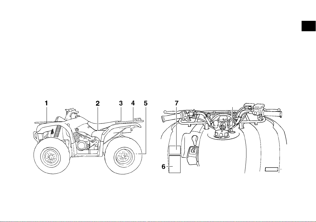
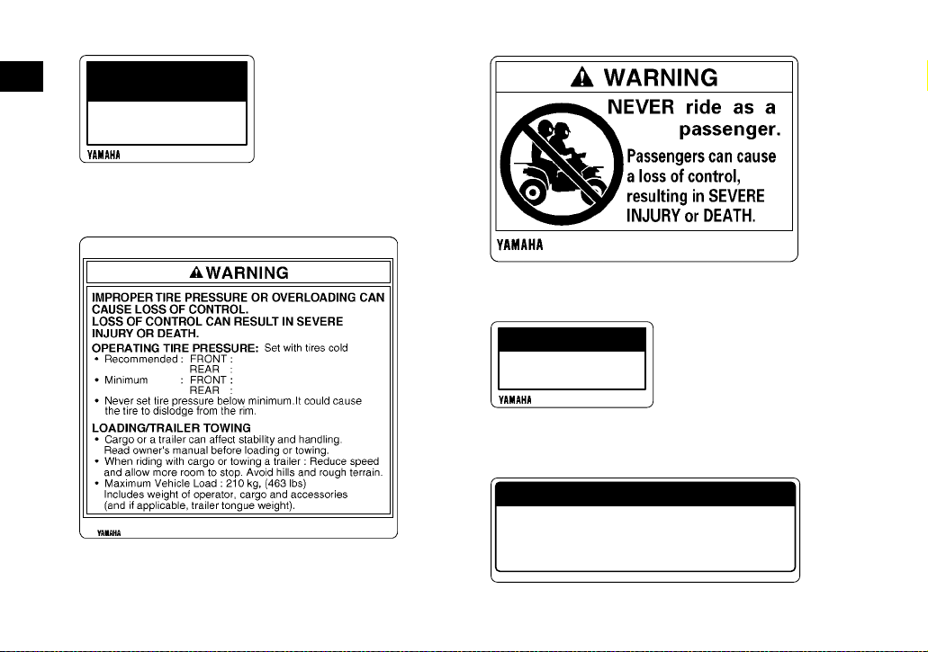
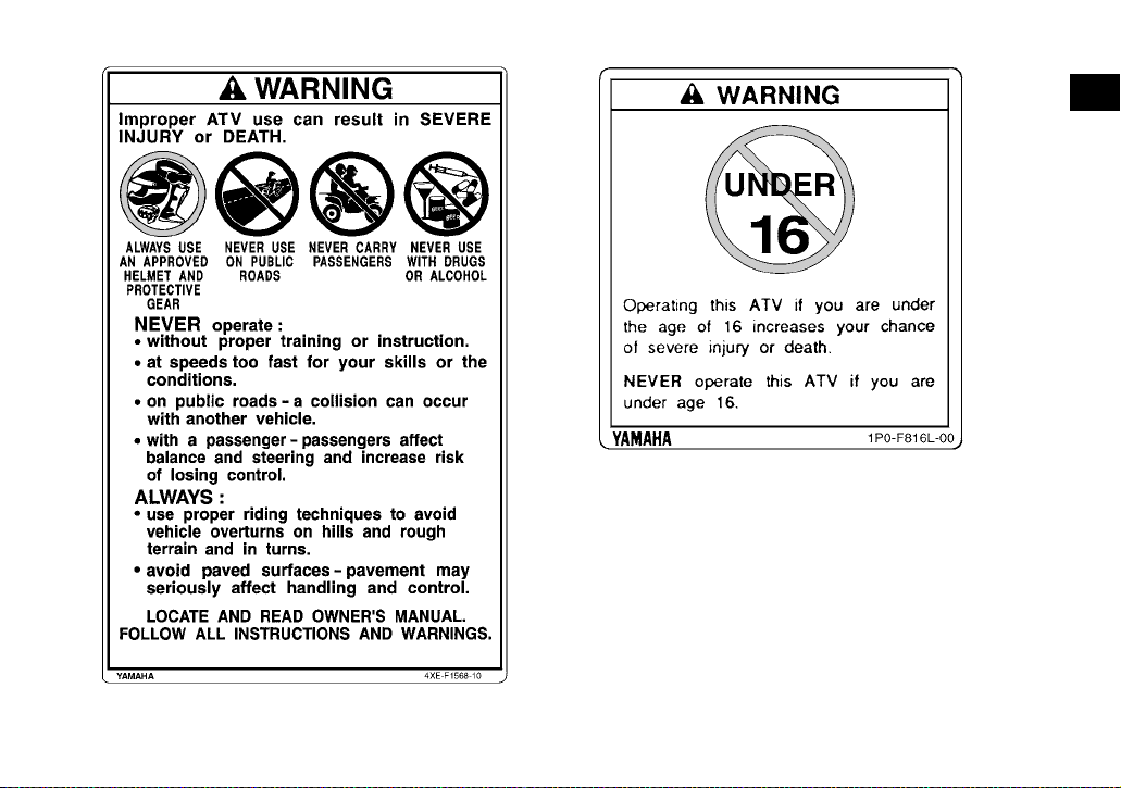
LOCATION OF THE WARNING AND SPECIFICATION LABELS
EBU30290
Read and understand all of the labels on your ATV. These labels contain important information for safe and
proper operation.
Never remove any la bels from your ATV. If a label becomes di fficult to read or comes off, r equest a replace ment label from your Yamaha dealer.
For Europe
8
9
1
1-1
Page 12
1
3
1
<
40 kg
( 88 lbs)
37S-F817R-00
2
1P0-F816P-20
4
<
80 kg
( 176 lbs)
25.0 kPa
0.25 kgf/cm²
3.6 psi
25.0 kPa
0.25 kgf/cm²
3.6 psi
5FU-F816M-M0
1-2
37S-F817R-10
5
<
4900 N
<
500 kgf
<
1102 lbf
<
147 N
<
15 kgf
<
33 lbf
4S2-F817S-00
Page 13
67
1P0-F816L-20
8
1
1P0-F816R-00
9
2011
YAMAHA MOTOR CO., LTD.
2500 SHINGAI, IWATA, JAPAN
1-3
YFM350FWA
15.9 kW
255 kg
1NS-F155A-00
Page 14
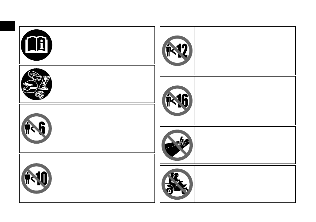
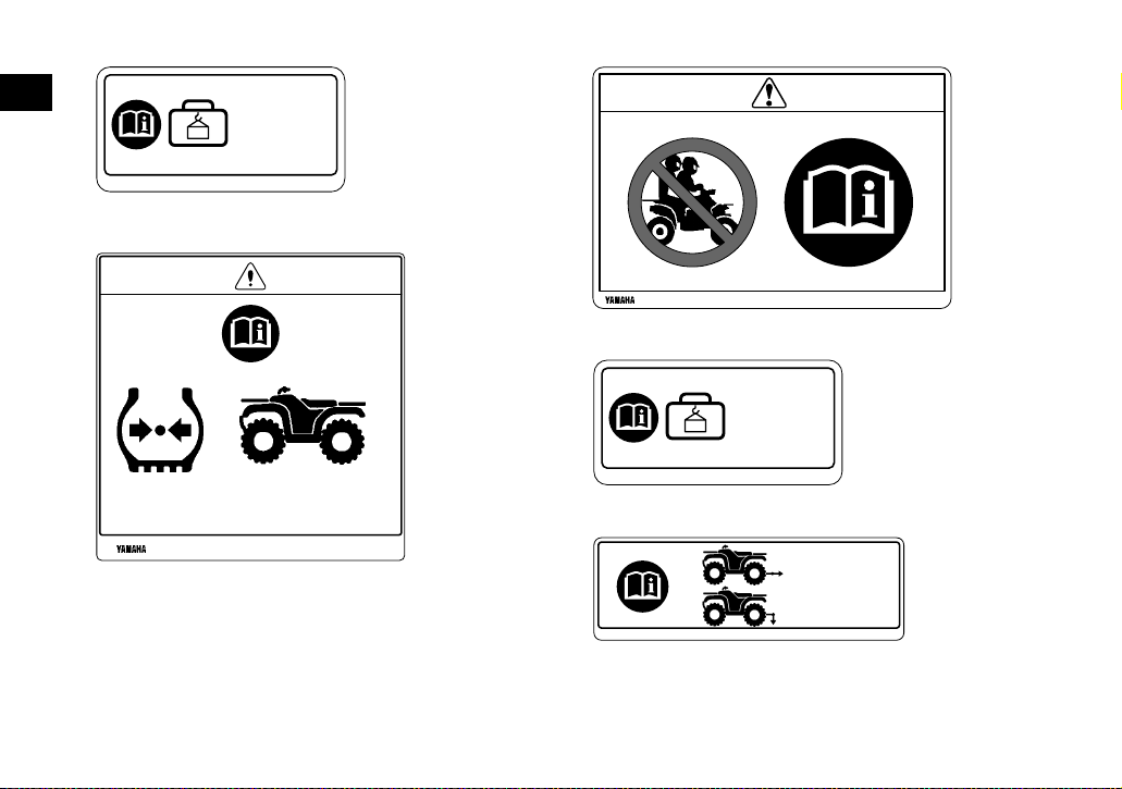
Familiarize your s e lf wi th th e fol l ow in g p i ct og ram s an d re ad th e ex p la na tory t ex t, th en m ak e s ure to check
the pictograms that apply to your model.
1
Read the Owner’s manual.
ALWAYS use an approved helmet and
protective gear.
NEVER permit children under age 6 to
operate this ATV.
Operation of this ATV by children under the
age of 6 increases the risk of severe injury
or death.
Adult supervision required for children under
age 16.
NEVER permit children under age 10 to
operate this ATV.
Operation of this ATV by children under the
age of 10 increases the risk of severe injury
or death.
Adult supervision required for children under
age 16.
NEVER permit children under age 12 to
operate this ATV.
Operation of this ATV by children under the
age of 12 increases the risk of severe injury
or death.
Adult supervision required for children under
age 16.
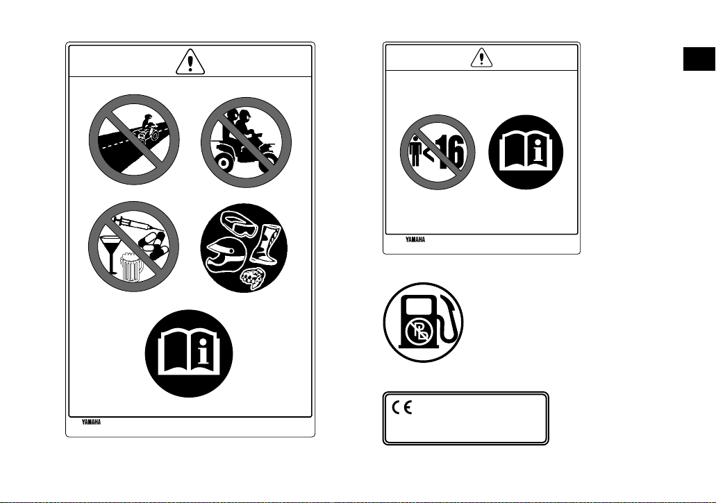
NEVER operate this ATV if you are under
age 16.
Operating this ATV if you are under the age
of 16 increases your chance of severe injury
or death.
NEVER use on paved roads.
NEVER carry passengers.
1-4
Page 15
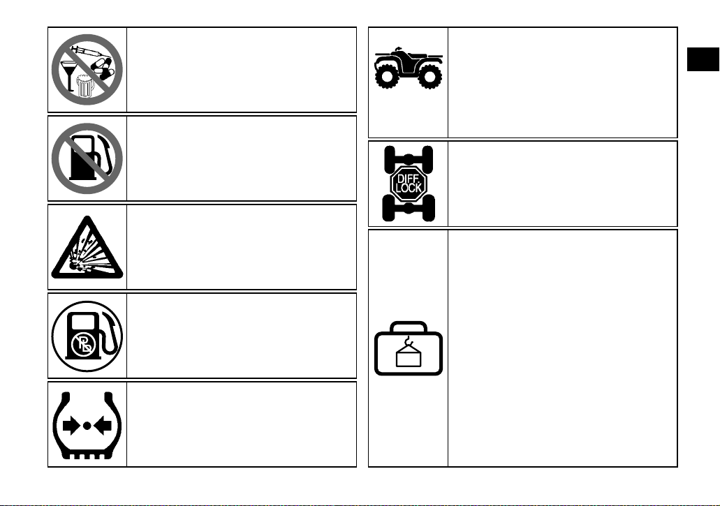
NEVER use with drugs or alcohol.
NEVER store fuel or flammable liquids.
This unit contains high-pressure nitrogen
gas.
Mishandling can cause an explosion. Do not
incinerate, puncture or open.
Use unleaded gasoline only.
Measure the tire pressure when the tires are
cold.
**.* kPa
*.** kgf/cm²
*.* psi
Adjust the tire pressure.
Improper tire pressure can cause loss of
control.
Loss of control can result in severe injury or
death.
**.* kPa
*.** kgf/cm²
*.* psi
Turning the ATV in 4WD-LOCK
(“DIFF.LOCK”) takes more effort.
Operate at a slow speed and allow extra
time and distance for maneuvers to avoid
loss of control.
This pictogram shows the loading limits
and/or maximum load capacity for this ATV.
Follow all load limits and other loading
guidelines in this manual.
Load may include the driver, passenger,
human protective gear, accessories, goods,
luggage, and all other load related items.
Make sure you do not exceed the load limits.
Overloading can cause loss of control.
Loss of control can result in severe injury or
death.
1
1-5
Page 16
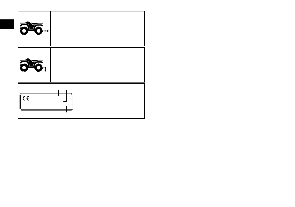
This pictogram shows trailer Hitch Tow
1
weight limit. (Combined weight of the trailer
and all cargo in the trailer.)
Overloading can cause loss of control.
Loss of control can result in severe injury or
death.
This pictogram shows trailer Hitch Tongue
weight limit. (Weight on the trailer tongue.)
Overloading can cause loss of control.
Loss of control can result in severe injury or
death.
1 2 3
****
YAMAHA MOTOR CO., LTD.
2500 SHINGAI, IWATA, JAPAN
******
*** kW
*** kg
4
1
Year of construction
2
Model Name
3
Max. Power
4
Mass In Running Order
1-6
Page 17
For Oceania
1
1-7
Page 18
13
1
LOAD LIMIT
40 kg{88 lbs}
5ND-F4877-20
2
4
25 kPa, (3.6 psi)
25 kPa, (3.6 psi)
22 kPa, (3.2 psi)
22 kPa, (3.2 psi)
LOAD LIMIT
80 kg{176 lbs}
5ND-F4897-20
5
MAXIMUM LOADING LIMIT
5FU-F816M-20
PULLING LOAD: 4900 N (500 kgf)
TONGUE WEIGHT: 147 N ( 15 kgf)
1102 lbf
33 lbf
5ND-F151K-00
1-8
Page 19
67
1
1-9
Page 20
EBU17431
SAFETY INFORMATION
EBU17564
2
AN ATV IS NOT A TOY AND CAN BE HAZARDOUS TO OPERATE.
An ATV handles diff erentl y fr om othe r vehicl es, in cluding motorcycles and cars. A collision or rollover can occur quickly, even during routine
maneuvers suc h as turning and riding on hill s or
over obstacle s, if you fail to take proper precautions.
SEVERE INJURY OR DEATH can result if you do
not follow these instructions:
● Read this manual and all la bels carefully and fol -
low the operating procedures described.
● Never operate an ATV without proper training or
instruction.
● Always follow the age recommendation:
– A child under 16 years old should never operate an ATV with en gin e size g rea te r than 90 c c.
● Never allow a child under age 16 to operate an
ATV without adult supervision, and never allow
continued use of an ATV by a child if he or she
does not have the abilities to operate it safely.
● Never carry a passenger on a n ATV.
● Always avoid operating an ATV on any paved
surfaces, includ ing sidewalks, drive ways, parking lots and paved st ree ts.
● Never operate an ATV on any paved street,
paved road or mo t or way .
● Watch carefully for other vehicles when operat-
ing on unpaved public streets or roads. Make
sure you know your country’s laws and reg ulations before you ride on unpav ed public s treets
or roads.
● Never operate an ATV without wearing an ap-
proved motorcycle helmet that fits properly. You
should also we ar eye prot ection (gog gles or face
shield), gloves, boots, a long-sleeved shirt or a
jacket, and long pants.
● Never consume alcohol or drugs before or while
operating this ATV.
● Never operate at speeds too fast for your skills
or the riding conditions. Alway s go at a speed
that is proper for the terrain , visibilit y, operat ing
conditions, and your experience.
● Never attempt wheelies, jumps, or other stunts.
2-1
Page 21

● Always inspect your ATV e ach time yo u use it t o
make sure it is in safe operating condition. Always follow the inspection and maintenance
procedures and schedules described in this
manual.
● Always keep both hand s on the ha nd le ba rs an d
both feet on the footboards of the ATV during
operation.
● Always go slowly and be extra careful when op-
erating on unfami liar terrain. Alwa ys be alert to
changing ter rain condit ions when operating the
ATV.
● Never operate on ex cess ive ly r o ug h, sli pp ery or
loose terrain until you have learned and practiced the skills necessary to control the ATV on
such terrai n. Always be especially c autious on
these kinds of terr ain .
● Always follow proper procedures fo r turning as
described in this manu al. P racti ce tur ning at low
speeds before attempting to turn at faster
speeds and never turn at excessive speeds.
● Never operate the ATV on hills too steep for the
ATV or for your abilities. Practice on smaller hills
before attempting larger hills.
● Always follow proper procedures for climbing
hills as described in this manual. Check the terrain carefully before you start up any hill. Never
climb hills with excessivel y slippery or loose surfaces. Shift your weight forward. Never open the
throttle sudd enl y. N ev er g o o ve r th e to p o f a h i ll
at high speed.
● Always follow proper procedures for going down
hills and for brak ing on hills as desc ribe d in thi s
manual. Check the terrain careful ly before you
start down any hill. Shift your weight backward.
Never go down a hill at high speed. Avoid going
down a hill at an angle that would cause the vehicle to lean sharply to one side. Go straight
down the hill where possible.
● Always follow proper procedures for crossing
the side of a hill as described in this manual.
Avoid hills with excessivel y slippery or loose su rfaces. Shif t your weig ht to the up hill side of the
ATV. Never attemp t to turn the ATV a round on
any hill until you ha ve mastered the tur ning technique descri bed i n this manu al on leve l gr ound .
Avoid crossing the side of a steep hill if possible.
● Always use prope r pr ocedures if you stall or ro ll
backwards when climbing a hill. Maintain a
steady speed when climbing a hill. If you stall or
2
2-2
Page 22

roll backwards, follow the special procedure for
braking described in this manual. Dismount on
the uphill side or to a s i de if po in ted s tr aig ht u phill. Turn the ATV around and remount, following
2
the procedure described in this manual.
● Always check for obstacles before operating in a
new area.
● Never attempt to operate over large ob stacles,
such as large rocks or fallen tre es. Always follow
proper procedur es when operating ov er obstacles as describe d in thi s ma nu al .
● Always be careful when skidding or sliding.
Learn to safely control skidding or sliding by
practicing at lo w speeds and on level, s mooth
terrain. On extremely sl ipp er y surfa ces, such a s
ice, go slowly and be very cautious in order to reduce the chance of skidding or sliding out of control.
● Never operate an ATV in fast flowing water or in
water deeper than that recommended in this
manual. Remembe r that wet brakes may have
reduced stoppi ng abili ty. Test your brakes af ter
leaving water. If necessary, apply them several
times to let friction dry out the linings.
● Always be sure there ar e no obstacles or people
behind you when yo u op er a te in re ve r s e. When
it is safe to proceed in reverse, go slowly.
● Always use the size and type of tires specified in
this manual .
● Always maintain proper tire pressure as de-
scribed in this manual.
● Never modify an ATV through improper installa-
tion or use of accessories.
● Never exceed the stated load capacity for an
ATV. Cargo should be properly distributed and
securely attach ed. R ed uc e spe ed an d fo ll ow instructions in this manual for carrying cargo or
pulling a trailer. All ow greate r distance fo r braking.
EWB00072
WARNING
Avoid Carbon Monoxide Poisoning
All engine exhaust contains carbon monoxide,
a deadly gas. Breathing carbon monoxide can
cause headaches, dizziness, drowsiness, nausea, confusion, and eventually death.
Carbon Monoxide is a colorless, odorless,
tasteless gas which may be present even if you
do not see or smell any engine exhaust. Deadly
levels of carbon monoxide can collect rapidly
2-3
Page 23
and you can quickly be overcome and unable
to save yourse lf. A lso , deadly levels of c ar bo n
monoxide can linger for hours or days in enclosed or poorly ventilated areas. If you experience any symptoms of carbon monoxide
poisoning, leave the area immediately, get
fresh air, and SEEK MEDICAL TREATMENT.
● Do not run engine indoors. Even if you try to
ventilate engine exhaust with fans or open
windows and doors, carbon monoxide can
rapidly reach dangerous levels.
● Do not run engine in poorly ventilated or par-
tially enclosed areas such as barns, garages,
or carports.
● Do not run engine outdoors where engine
exhaust can be drawn into a building
through openings such as windows and
doors.
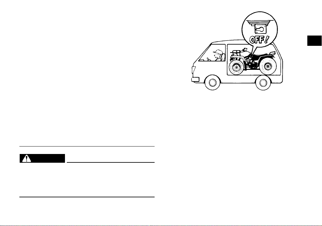
EWB02591
WARNING
When transporting the ATV in another vehicle,
be sure it is kept upright and that the fuel cock
is in the “OFF” position. Otherwise, fuel may
leak out of the carburetor or fuel tank.
2
2-4
Page 24
EBU17680
DESCRIPTION
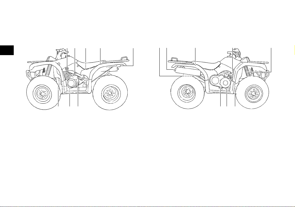
EBU17690
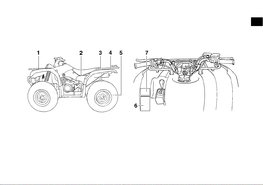
Left view
3
9
1. Fuel cock
2. Throttle stop screw
3. Air filter case
4. Fuses
5. Battery
6. Tail/brake light
7. Engine oil filler cap
8. Oil filter cartridge
9. V-belt cooling duct check hose
3 4,51 26
87
EBU17700
Right view
12 3 4 5
678
1. Rear shock absorber assembly spring preload adjusting
ring
2. Spark arrester
3. Storage compartment and tool kit
4. Spark plug
5. Front shock absorber assembly spring preload adjusting
ring
6. Rear brake light switch
7. Brake pedal
8. V-belt case drain plug
3-1
Page 25
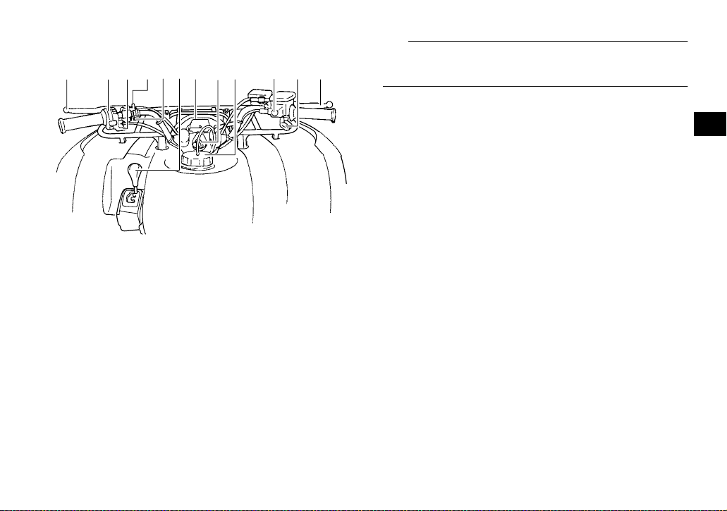
EBU17712
Controls and instruments
1234 10567 89 1112
1. Rear brake lever
2. Handlebar switches
3. Starter (choke)
4. P arking brake lock plate
5. Horn switch
6. Drive select lever
7. Speedometer
8. Main switch
9. Fuel tank cap
10.On-Command four-wheel-drive switch
11.Throttle lever
12.Front brake lever
TIP
The ATV you have purchased may differ slightly
from the figures shown in this manual.
3
3-2
Page 26
EBU17733
INSTRUMENT AND CONTROL FUNCTIONS
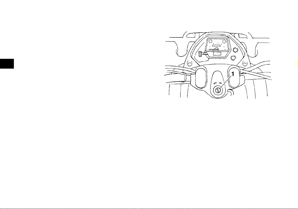
EBU17770
Main switch
The positions of the main switch are as follows:
ON
All electrical systems are supplied with power. The
4
headlights, meter lighting and taillight come on
when the light switch is on, and the engine can be
started. The key cannot be removed.
OFF
All electrical systems are off. The key can be removed.
1. Main switch
4-1
Page 27
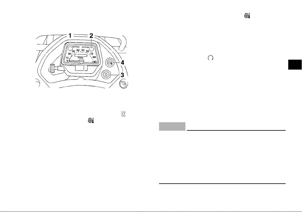
EBU17815
Indicator lights and warning light
1. Reverse indicator light “REVERSE”
2. Neutral indicator light “NEUTRAL”
3. On-Command four-wheel-drive indicator light “”
4. Oil temperature warning light “”
EBU17870
Neutral indicator light “NEUTRAL”
This indicator light comes on when the transmission is in the neutral position.
EBU17850
Reverse indicator light “REVERSE”
This indicator light comes on when the transmission is in the reverse position.
EBU26932
Oil temperature warning light “”
This warning light comes on when the engine overheats. When this occurs, stop the engine as soon
as it is safe to do so, and allow it to cool.
The electrical circuit of the warning light can be
checked by turning the key to “ON”, with the engine
stop switch set to “”, and then pushing the start
switch.
If the warning light does not come on while the start
switch is being pushed, or if the warning light remains on after the start switch is released, have a
Yamaha dealer check the electrical circuit.
If the warning light stays on when the engine is
cool, have a Yamaha dealer check the electrical
circuit.
ECB00010
NOTICE
● The engine may overheat if the ATV is over-
loaded. In this case, reduce the load to specification.
● Start the engine after making sure that the
warning light is out. Continuous use while
the warning light is on may cause damage to
the engine.
4
4-2
Page 28
EBU17952
On-Command four-wheel-drive indicator
light “”
This indicator light comes on when the On-Command four-wheel-drive switch is set to the “4WD”
position.
TIP
Due to the synchronizing mechanism in the differ-
4
ential gear case, the light may not come on until
the ATV starts moving.
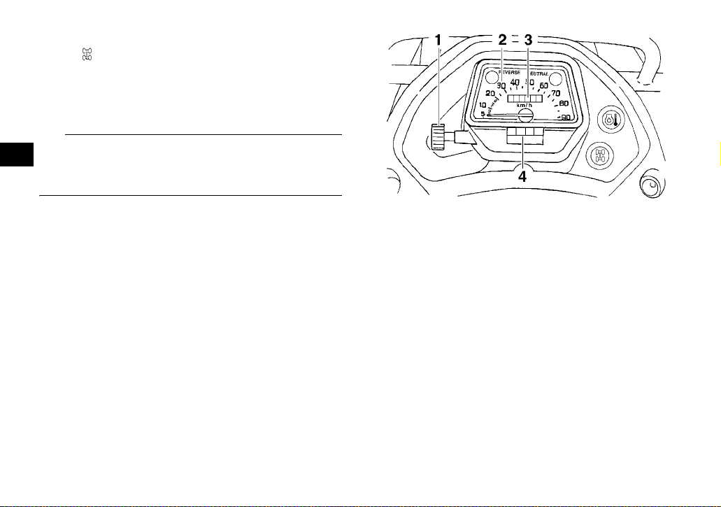
EBU18022
Speedometer
This speedometer is equipped with an odometer
and a tripmeter. The tripmeter can be reset to zero
with the reset knob. Use the tripmeter to estimate
how far you can ride on a tank of fuel before going
to reserve. This information will enable you to plan
fuel stops in the future.
1. Reset knob
2. Speedometer
3. Odometer
4. Tripmeter
4-3
Page 29
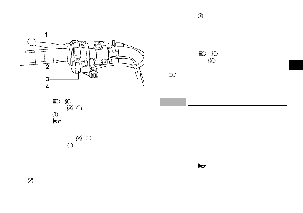
EBU18061
Handlebar switches
1. Light switch “ //OFF”
2. Engine stop switch“ / ”
3. Start switch “”
4. Horn switch“”
EBU18080
Engine stop switch “ / ”
Set this switch to “” before starting the engine.
The engine stop switch controls the ignition and
stops the engine when it is running. Use this switch
to stop the engine in an emergency situation. The
engine will not sta rt or run whe n this switc h is set
to “”.
EBU18101
Start switch “”
Push this switch to crank the engin e with the st arter. See the star ting instr uctions o n page 6- 1 prior
to starti ng the engine.
EBU18163
Light switch “ //OFF”
Set this switc h to “” to turn on the low beam s,
the taillight and the meter lighting. Set th e switch
to “” to turn on the high be ams, th e tailli ght an d
the meter lightin g. Set the s witch to “OFF” to turn
off all the lights.
ECB00043
NOTICE
Do not use the headlights with the engine
turned off for an extended period of time, otherwise the battery may discharge to the point
that the starter motor will not operate properly.
If this should happen, remove the battery and
recharge it. (See page 8-39.)
EBU18170
Horn switch “”
Press the switch to so un d the horn .
4
4-4
Page 30
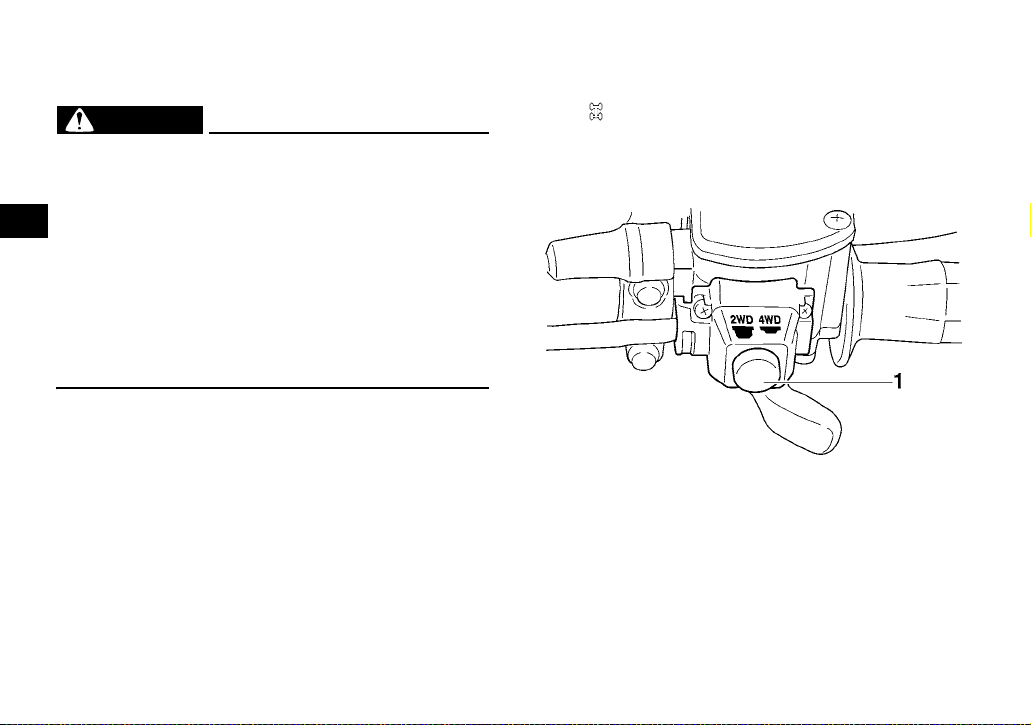
EBU28432
On-Command four-wheel-drive switch
“2WD”/“4WD”
EWB00163
WARNING
Always stop the ATV before changing from
two-wheel drive to four-wheel drive and vice
versa. The ATV handles differently in twowheel drive than in four-wheel drive in some
4
circumstances. Changing from two-wheel
drive to four-wheel drive or vice versa while
moving may cause the ATV to unexpectedly
handle differently. This could distract the operator and increase the risk of losing control and
of causing an accident.
This ATV is equipped with a switch to change from
two-wheel drive to four-wheel drive and vice versa.
Select the appropriate drive according to the terrain and the conditions.
● “2WD” (two-wheel drive): Power is supplied to
the rear wheels.
● “4WD” (four-wheel drive): Power is supplied to
the rear and front wheels.
To change from two-wheel drive to four-wheel
drive, stop the ATV and push the switch in to the
“4WD” position. The four-wheel-drive indicator
light “” comes on.
To change from four-wheel drive to two-wheel
drive, stop the ATV and push the switch in to the
“2WD” position.
1. On-Command four-wheel-drive switch “2WD”/“4WD”
EBU18282
Throttle lever
Once the engine is running, pushing the throttle lever will increase the engine speed.
4-5
Page 31

Regulate the speed of the ATV by varying the
throttle position. Because the throttle is springloaded, the AT V will decelera te, and the engi ne will
return to an idle any time the throttle lever is released.
1. Throttle lever
Before starting the engine, check the throttle to be
sure it is operating smoothly. Make sure it returns
to the idle position as soon as the lever is released.
EBU18323
Speed limiter
Your ATV is equipped with an adjustable speed
limiter. The spe ed limiter keeps the thro ttle from
fully opening, even when the throttle lever is
pushed to the maximum.
1. Loosen the locknut.
2. To i ncrease the maximum engine power a vailable and the maximum speed of the ATV, turn
the adjusting screw in direction (a). To decrease the max imum engine power avai lable
and the maximum speed of the ATV, turn the
adjusting screw in direction (b). Do not turn
the adjusting screw out more than 12 mm
(0.47 in) or the throttle cable could be damaged. Always make sure the throttle lever free
play is adjusted to 3.0–5.0 mm (0.12–0.20 in).
(See page 8-26 .) WARNING! Improper ad-
justment of the speed limiter and t hrottle
could cause throttle cable damage or improper throttle operation. You could lose
control, resulting in an accident.
[EWB00241]
4
4-6
Page 32

4
1. Locknut
2. Adjusting screw
3. No more than 12 mm (0.47 in)
3. Tighten the locknut.
EBU18391
Front brake lever
The front brake lever is located on the right handlebar. To apply the front brake, pull the brake lever
toward the handlebar grip.
1. Front brake lever
EBU18442
Brake pedal and rear brake le ver
The brake pe da l is l oc a te d o n the r i gh t si de of th e
ATV and the rear brake lever is located on the left
handlebar. To ap pl y t he rea r br a ke, push do wn on
the brake pedal or pull the brake lever toward the
handlebar gri p.
4-7
Page 33

1. Brake pedal
1. Rear brake lever
EBU18461
Parking brake
Use the parking brake before starting the engine or
after parking the ATV, especially on a slope. Apply
the rear brake lever and push down the lock plate
to apply the parking brake. Squeeze the rear brake
lever to release the parking brake.
4
1. P arking brake lock plate
EWB00220
WARNING
● Always set the parking brake before starting
the engine. The ATV could start moving unexpectedly if the parking brake is not applied. This could cause loss of control or a
collision.
4-8
Page 34

● Always be sure you have released the park-
ing brake before you begin to ride. The brake
could overheat if you ride the ATV without releasing the parking brake. You could lose
braking performance which could cause an
accident. You could also wear out the brakes
prematurely.
4
EBU18581
Drive select lever
The drive select lever is used to shift your ATV into
the forward, neutral and reverse positions. See the
“Operating the drive select lever and driving in reverse” section on page 6-3 for the dr ive select lever
operation.
1
1. Drive select lever
EBU18720
Fuel tank cap
Remove the fuel tank cap by turning it counterclockwise.
4-9
Page 35

1. Fuel tank cap
EBU18754
Fuel
Make sure there is su ff ic ien t gas oli ne in the ta nk.
EWB02521
WARNING
Gasoline and gasoline vapors are extremely
flammable. To avoid fires and explosions and
to reduce the risk of in jur y w hen re fu eli ng , fo llow these inst r u cti on s.
1. Before refueling, turn off the engine and be
sure that no one is sitting on the vehicle. Never refuel while smoking, or while in the vicinity
of sparks, open flames, or other sources of ignition such as th e pilot lights of w at er he at ers
and clothes dryers.
2. Do not overfill the fuel tank. W hen refueling,
be sure to insert the pump nozzle into the fuel
tank filler hole. Stop filling when the fuel reaches the bottom of the fi ller tube. Because fuel
expands when it heats up, heat from the engine or the sun can cause fuel to spill out of
the fuel tank.
1. Maximum fuel level
2. Fuel tank filler tube
4
4-10
Page 36

Recommended fu e l:
UNLEADED GASOLINE ONLY
For Euro pe: Regular un leaded gaso line only
with a research octane number of 91 or
higher
Fuel tank capacity:
13.5 L (3.57 US ga l, 2.97Imp.gal)
Fuel reserve amount:
4
3.3 L (0.87 US gal, 0.73 Imp.gal)
doctor immediately. If gasoline spills on y our
skin, wash with soap and water. If gasoline
spills on your clothing, change your clothes.
ECB00070
NOTICE
Use only unleaded gasoline. The use of leaded
gasoline will cause severe damage to internal
engine parts, such as the valves and piston
rings, as well a s t o t he ex h aus t syst e m.
3. Wipe up any spilled fuel immediately.
NOTICE: Immediately wip e off spilled fuel
with a clean, dry, soft cloth, since fuel may
deteriorate painted surfaces or plastic
[ECB00981]
parts.
4. Turn the fuel tank cap fully clockwise to make
sure it is securely closed.
EWB02531
WARNING
Gasoline is poisonous and can cause injury or
death. Handle gasoline with care. Never siphon
gasoline by mouth. If you should swallow
some gasoline or inhale a lot of gasoline vapor,
or get some gasoline in your eyes, see your
Your Yamaha engin e has been designed to use
regular unleaded gasoline with a research octane
number of 91 or higher. If knocking (or pinging) occurs, use a gasoline of a different brand . Use of unleaded fuel will extend spark plug life and reduce
maintenance costs.
EBU18820
Fuel cock
The fuel cock supplies fuel from the tank to the carburetor while also f ilte r ing it .
The fuel cock lev er pos iti ons ar e exp laine d as fo llows and shown in the illustrations.
4-11
Page 37

OFF
1. Arrow mark pointing to “OFF” 1. Arrow mark pointing to “ON”
ON
4
With the fuel cock lever in this position, fuel will not
flow. Always turn the fuel cock lever to this position
when the engi ne is no t r u nn ing.
With the fuel cock l ever in this p osition, fue l flows
to the carburetor. Tur n the fuel cock lever to this
position when starting the engine and riding.
4-12
Page 38

RES
4
1. Arrow mark pointing to “RES”
This indicates reserve. With the fuel cock lever in
this position, the fuel reserve is made available.
Turn the fuel cock l ever to this po sition if you ru n
out of fuel while riding. When this occurs, refuel as
soon as possible and be sure to turn the fuel cock
lever back to “ON”!
EBU18850
Starter (choke) “”
Starting a cold engine requir es a richer air-fu el mixture, which is supplied by the starter (choke).
Move the starter (choke) in direction (a) to turn on
the starter (choke).
Move the starter (choke) in direction (b) to turn off
the starter (choke).
See the “Starting a cold engine” section on page
6-1 for proper op era t ion .
1. Starter (choke) “”
EBU18881
Seat
To remove the seat
Pull the seat lo ck lever upward and pull up the seat
at the rear.
4-13
Page 39

4
1. Seat
2. Seat lock lever
To install the seat
Insert the project ions on the front of th e seat into
the seat holders and push down on the seat at the
rear. Make sure that the seat is securely fitted.
1. Projection
2. Seat holder
EBU18912
Storage compartment
ECB00130
NOTICE
Do not store metal or sharply edged objects,
like tools, in the stor age compartment. If they
must be stored, wrap them in appropriate
cushion material to prevent damaging the storage compartment.
4-14
Page 40

1
4
1. Storage compartment
● Do not excee d the loa d limit of 2.0 kg (4 lb) for
the storage compartment.
● Do not excee d the maximum load of 210.0 kg
(463 lb) for the ATV.
TIP
There is a check hose at the bottom of the storage
compartment. If any water collects in this hose, remove the hose, empt y it , and th en ins ta ll it .
1. Storage compartment check hose
EBU18962
Front carrier
● Do not exceed the load limit of 40.0 kg (88 lb) for
the front carrier.
● Do not exceed t he maximum load of 21 0.0 kg
(463 lb) for the ATV.
EBU18972
Rear carrier
● Do not exceed the load limit of 80.0 kg (176 lb)
for the rear carrier.
● Do not exceed t he maximum load of 21 0.0 kg
(463 lb) for the ATV.
4-15
Page 41

EBU18993
Adjusting the front shock absorber assemblies
The spring preload can be adjusted to suit the rider’s weight and the riding conditions.
EWB00400
WARNING
Always adjust the shock absorber assemblies
on the left and right side to the same setting.
Uneven adjustment can cause poor handling
and loss of stability, which could lead to an accident.
Adjust the sprin g pr eload as f ol lows.
Turn the spring preload adjusting ring in direction
(a) to increase the spring preload and thereby
harden the suspe nsion, an d in dire ctio n (b) to de crease the spring preload and thereby soften the
suspension.
Align the appropriate notch in the adjusting ring
with the position indicator on the shock absorber.
4
1. Spring preload adjusting ring
2. Posi tion indicator
TIP
A special wrench can be obtained at a Yamaha
dealer to make this adjustment.
4-16
Page 42

4
1. Special wrench
Spring preload setting:
Minimum (soft):
1
Standard:
2
Maximum (hard):
5
EBU19023
Adjusting the rear shock ab sorbe r as sembly
The spring preload can be adjusted to suit the rider’s weight and the riding conditions.
ECB01090
NOTICE
Never turn the adjusting mechanism beyond
the minimum and maximum settings.
Adjust the spring preload as follows.
Turn the spring preload adj usting ring i n directio n
(a) to increase the spring preload and thereby
harden the suspension, and in direction (b) to decrease the s pring preload and thereby soften the
suspension.
1. Spring preload adjusting ring
2. Position indicator
4-17
Page 43

TIP
A special wrench can be obtained at a Yamaha
dealer to make this adjustment.
1. Special wrench
Spring preload setting:
Minimum (soft):
1
Standard:
2
Maximum (hard):
5
4
4-18
Page 44

EBU19201
PRE-OPERATION CHECKS
EBU19224
Inspect your vehicle each time you use it to make sure the vehicle is in safe operating condition. Always
follow the inspection and maintenance procedures and schedules described in the Owner’s Manual.
EWB00481
WARNING
Failure to inspect or maintain the vehicle properly increases the possibility of an accident or equipment damage. Do not operate the vehicle if you find any problem. If a problem cannot be corrected
5
by the procedures provided in this manual, have the vehicle inspected by a Yamaha dealer.
Before using this vehicle, check the following points:
ITEM ROUTINE PAGE
Fuel
Engine oil
Final gear oil • Check ATV for oil leakage. Correct if necessary. 5-3, 8-15
Differential gear oil • Check ATV for oil leakage. Correct if necessary. 5-3, 8-18
• Check fuel level in fuel tank, and add recommended fuel if necessary.
• Check fuel line for leakage. Correct if necessary.
• Check oil level in engine, and add recommended oil to specified lev-
el if necessary.
• Check ATV for oil leakage. Correct if necessary.
4-10, 5-3
5-3, 8-11
5-1
Page 45

ITEM ROUTINE PAGE
• Check operation. If soft or spongy, have Yamaha dealer bleed hydraulic system.
Front brake
Rear brake
Throttle lever
Control cable s • Make sure that operation is smooth. Lubricate if necessary. 8-36
Wheels and tires
Brake pedal
Brake levers
Axle boots • Check for cracks or damage, and replace if necessary . 8-35
Chassis fasteners • Make sure that all nuts, bolts and screws are properly tightened. 5-6
Instruments, lights and
switches
• Check brake pads for wear, and replace if necessary.
• Check brake fluid level in reservoir, and add specified brake fluid to
specified level if necessary.
• Check hydraulic system for leakage. Correct if necessary.
• Check operation, and correct if necessary.
• Lubricate cables if necessary.
• Check lever and pedal free play, and adjust if necessary.
• Make sure that operation is smooth. Lubricate cable and lever hous-
ing if necessary.
• Check lever free play, and adjust if necessary.
• Check wheel condition, and replace if damaged.
• Check tire condition and tread depth. Replace if necessary.
• Check air pressure. Correct if necessary.
• Make sure that operation is smooth. Lubricate pedal pivoting point if
necessary.
• Make sure that operation is smooth. Lubricate lever pivoting points if
necessary.
• Check operation, and correct if necessary. 5-6
5-3, 8-27, 8-29, 8-30
5-3, 8-27, 8-30
5-4, 8-26
5-4
8-37
8-37
5
5-2
Page 46

EBU19541
Fuel
Make sure that ther e is sufficient fuel in th e tank.
(See page 4-10.)
EBU19560
Engine oil
Make sure that the engi ne oil is at the specified lev el. Add oil as necessary. (See page 8-11.)
EBU19590
5
Final gear oil
Make sure th at the fi na l g ea r oi l is at the specif ie d
level. Add oil as necessary. (See page 8-15.)
EBU19600
Differential gear oil
Make sure that the differential gear oil is at the
specified level. Add oil as necessary. (See page
8-18.)
EBU27672
Front and rear brakes
Brake levers and brake pedal
● Check that there is no f ree play in the fr ont brake
lever. If there is free play, have a Yamaha dealer
check the brake system.
● Check for correct free play in the rear brake lever
and brake peda l. If the f ree pl ay i s in cor r ect , adjust it. (See page 8-30.)
● Check operat ion of the levers and pedal. They
should move smoothly and there should be a
firm feeling when the brake is applied. If not,
have a Yamaha dealer check them.
Brake fluid level (front brake)
Check the brake fluid level. Add fluid if necessary.
(See page 8-29.)
Specified brake fluid:
DOT 4
Brake fluid leakage (front brake)
Check to see if any br ake fl uid is le aking out o f the
hose, joint or brake fluid reservoir of the front
brake. Apply the brake firmly for one minute. If the
lever moves slowly inward, the re may be a leak in
the brake syst em. If there is any lea kage, the bra ke
system should be checked by a Yamaha dealer.
5-3
Page 47

Brake operation
Test the brakes at slow speed after starting out to
make sure they ar e wor king p roper ly. If the b rakes
do not provide proper braking performance, check
the brake pads and shoes for wear. (See page
8-27.)
EBU19761
Throttle lever
Check the operatio n of the throttle lever. It must
open smoothly and spring back to the idle position
when released. Have a Yamaha dealer correct if
necessary.
EBU19814
Tires
Check tire pressure regularly to make sure it is at
the recommended specifications. Also check for
wear and damag e.
Tire pressure
Use the low-pre ssu re tir e ga uge t o che ck and adjust tire pressures when the tires are cold. Tire
pressures must be equal on both sides.
WARNING! Operation of this vehicle with i mproper tire pr essure may cause seve re injury
or death from loss of control or rollover. Tire
pressure below the minimum specified could
also cause the tire to dislodge from the rim under severe riding conditions.
[EWB02541] Set tire
pressures to the following specifications:
Recommended tir e pr e ssur e:
Front
25.0 kPa (0.250 kgf/cm², 3.6 psi)
Rear
25.0 kPa (0.250 kgf/cm², 3.6 psi)
Minimum tir e pr essu re :
Front
22.0 kPa (0.220 kgf/cm², 3.2 psi)
Rear
22.0 kPa (0.220 kgf/cm², 3.2 psi)
Maximum tire seatin g pre ssure:
Front
250 kPa ( 2.5 k gf /c m², 36 psi)
Rear
250 kPa ( 2.5 k gf /c m², 36 psi)
The low-press ure tire gauge is includ ed as standard equipmen t. Make two m easurements of the
tire pressure and use the second reading. Dust or
dirt in the gauge could cause the first reading to be
incorrect.
5
5-4
Page 48

5
1. Low-pressure tire gauge
Tire wear limit
When the tire groove decreases to 3 mm (0.12 in)
due to wear, re pl ac e th e t ir e .
1. Tire wear limit
Tire information
This ATV is equipped with tubeless tires with
valves.
EWB02551
WARNING
Use of improper tires on this ATV may cause
loss of control, increasing your risk of an accident.
After extensive tests, only the tires listed below
have been approved for this model by Yamaha
Motor Manufacturing Corporation of America.
5-5
Page 49

Front:
Manufacturer/model:
YFM350FAB CHENG SHIN/C-828
YFM35FGB MAXXIS/MU13
Size:
AT25 x 8-12
Type:
Tubeless
Rear:
Manufacturer/model:
YFM350FAB CHENG SHIN/C-828
YFM35FGB MAXXIS/MU14
Size:
AT25 x 10-12
Type:
Tubeless
Aftermarket tires and rims
The tires and rims that came with your ATV were
designed to match the performance capabilities
and to provide t he best combination of handling,
braking, and co mfort. Ot her tire s, rims , sizes, and
combinations may not be appropriate.
EBU19840
Chassis fasteners
Make sure that all nuts, bolts and screws are properly tightened.
EBU19850
Instruments, lights and swit ches
Check that all ins tr ume nt s, li gh ts an d s wi tc hes ar e
working proper l y. C orr ect if nec essa ry.
5
5-6
Page 50

EBU19881
OPERATION
EBU19901
Read the Owner’s Manual carefully before riding
the ATV. If there is a control or function you do not
understand, ask your Yamaha dealer.
EWB00631
WARNING
Read the Owner’s Manual ca refully to b ecome
familiar with all c ontrols in order to help pre-
6
vent any loss of control, which could cause an
accident or injury.
EBU26953
Starting a cold engine
ECB00150
NOTICE
See the “Engine break-in” section on page 6-4
prior to operating the engine for the first time.
1. Set the parking brake.
2. Turn the fuel cock to “ON”.
3. Turn the key to “ON” and the engine stop
switch to “”.
4. Shift the drive select lever into the neutral position. The neutral indicator light should come
on. If the indicator light does not come on,
have a Yamaha deal er check the electric al circuit.
TIP
The engine can be started under the following conditions:
● The drive select lever is in the ne utra l posit io n.
● The rear brake leve r is appli ed with th e drive se -
lect lever in any position. However, it is recommended to shift into the neutral position before
starting th e en gi ne .
5. Use the starter (choke) in reference to the figure:
Position (1):
Cold engine start with ambient temperature
below 5 °C (40 °F).
Position (2):
Cold engine start with ambient temperature
between 0 °C (30 °F) and 30 °C (90 °F).
6-1
Page 51

Position (3):
Cold engine start with ambient temperature
above 25 °C (80 °F).
as possible to preserve battery energy. Do not
crank the engine more than 10 seconds on each
attempt.
Ambient temp./starter (choke) position
1. Fully open
2. Half open
3. Closed
4. Starter (choke)
6. Completely close th e throttle lever and sta rt
the engine by pushing the start switch.
TIP
If the engine fails to start, release the start switch,
then push it again. Pause a few seconds before
the next attempt. Each cranking shoul d be as short
7. If the en gine is st arted wit h the start er ( choke )
in position (1) , the starter (choke) should be
returned to position (2) to warm up the engine.
If the engi ne is st arted wit h t he star ter (choke )
in position (2), keep the starter (choke) in this
position to warm up the engine.
8. Continue warming u p the engine u ntil it idl es
smoothly, then return the starter (choke) to
position (3) before riding.
TIP
The engine is warm when it responds quickly to the
throttle with the starter (choke) turned off.
ECB00163
NOTICE
For maximum engine life, never accelerate
hard when the engine is cold!
6-2
6
Page 52

EBU20291
Starting a warm engine
Follow the sa me procedure as f or starting a c old
engine, with the exception that the starter (choke)
is not required when the engine is warm. Instead,
start the engine with the throttle slightly open.
EBU20382
Operating the drive select lever and driving in reverse
ECB00170
NOTICE
6
Before shifting, stop the ATV, otherwise the
transmission may be damaged.
Shifting: Forward
1. Bring t he ATV to a com pl ete sto p.
2. Apply the brake pedal.
3. Shift from neutr al to forwar d and vice versa b y
moving the drive select lever along the shift
guide.
TIP
Make sure that the drive select lever is completely
shifted into position.
1
F2
N3
R4
1. Drive select lever
2. F (Forward)
3. N (Neutral)
4. R (Rev erse)
4. Open the throttle lever gradually.
Shifting: Reverse
EWB00720
WARNING
Improper operation in reverse could make you
hit an obstacle or even a person behind you,
resulting in serious injury. When you shift into
reverse, make sure there are no people or obstacles behind you. When it is safe to proceed,
go slowly.
6-3
Page 53

1. Bring the ATV to a complete stop.
2. Appl y th e br ake pe da l.
3. Shift from neutral to reverse and vice versa by
moving the drive select lever along the shift
guide.
TIP
When in reverse, the reverse indicator light should
come on. If the ind icator light does n ot come on,
have a Yamaha dealer check the electrical circuit.
1
4. Check behind for people or obstacles, and
then release the brake pedal.
5. Open the throttle lever gradually and continue
to watch to the rear while backing.
EBU20682
Engine break-in
TIP
● For ATVs equipped with an odometer or an hour
meter, follow the figur es given i n km (mi) or the
figures given in hour s.
● For ATVs not equipped with an odometer or
hour meter, foll ow th e fi gu re s give n i n ho urs .
6
1. Drive select lever
2. F (Forward)
3. N (Neutral)
4. R (Reverse)
F2
N3
R4
There is never a more important period in the life of
your engine than the first 320 km (200 mi) or 20
hours of ridin g. For this reas on, you should re ad
the following ma t eri al ca ref ully.
Since the engine is brand new, do not put an excessive load on it f or the first 320 km ( 200 mi) or 20
hours. The various parts in the engine wear and
polish themselves to the correct operating clearances. During this period, prolonged full-throttle
operation or any condi tion that m ight res ult in e ngine overheating must be avoided.
6-4
Page 54

0–160 km (0–100 mi) or 0–10 hours
Avoid prolonged operation above 1/2 throttle. Vary
the speed of th e ATV reg ularly. Do not opera te it at
one set throttle position.
160–320 km (100–200 mi) or 10–20 hours
Avoid prolonged op er at io n a bov e 3/4 thr o ttl e . Rev
the engine freely, but do not use full throttle at any
time.
320 km (200 mi) or 20 hours and beyond
The ATV can now be oper at ed no rma lly .
6
ECB00220
NOTICE
If any engine trouble should occur during the
engine break-in period, immediately have a
Yamaha dealer ch ec k th e ATV.
EBU20702
Parking
When parking the ATV, apply the brake pedal, shift
the drive select lever into the forward position, stop
the engine, apply the parking brake, and then turn
the fuel cock to “OFF”.
1. P arking brake lock plate
EBU20764
Parking on a slope
EWB00831
WARNING
Avoid parking on hills or other inclines. Parking on a hill or other incline c ould cause the
ATV to roll out of control, increasing the
chance of an accident. If you must park on an
incline, place the ATV transversely across the
incline, shift the drive select lever to the forward position, stop the engine, apply the parking brake, and then block the front and rear
wheels with rocks or other objects.
6-5
Page 55

Never park the ATV on hills that are too steep
to walk up easily.
EBU20910
Accessories and loading
1. With the transmission in the forward position,
bring the ATV to a stop by applying the
brakes.
2. Stop the engine.
3. With the rear brake lever applied, apply the
parking brake, and then slowly release the
rear brake lev er.
4. Turn the fuel cock to “OFF”.
EBU20921
Genuine Yamaha Accessories
Choosing accessories for your ATV is an impo rtant
decision. Genuine Yamaha Accessories, which
are available only from a Yamaha dealer, have
been designed, tested, and approved by Yamaha
for use on your AT V. Many companies with no connection to Yamah a manu facture parts and acces sories or offer other modifications for Yamaha
vehicles. Yama ha is not in a position to tes t the
products that these aftermarket companies produce. Therefore, Yamaha can neither endorse nor
recommend the use of accessories not sold by
Yamaha or modifications not specifically recommended by Yama ha, e ven if sol d an d ins tall ed by
a Yamaha deal er .
Aftermarket parts, accessories, and modifications
While you may find aftermarket products similar in
design and qua lity to genuine Yamaha A ccessories, recognize that some aftermarket accesso ries
or modifications are not suitable because of potential safety hazards to you or others. Installing after-
6
6-6
Page 56

market products or having other modifications
performed to yo ur AT V that change any of th e v ehicle’s design or ope ration ch aracteri stics can put
you and others at greater risk of serious injury or
death. You ar e responsible for i njuries related to
changes in the vehicl e.
Keep the following in mind when considering an
accessory or operating an ATV which has accessories.
● Accessories should be rigidly and securely
mounted. An accessory which can shift position
or come off while you are riding could affect your
6
ability to control the ATV.
● Do not mount a n accessory where it could int er -
fere with your abi lity to contr ol the ATV. Examples include (but are not limited to) a heavy or
bulky object a ttached to the handlebars which
could make steering difficult, an accessory that
limits your ability to move around on the seat, or
one that limits your view.
● Use extra cau tion when ridi ng an ATV with ac-
cessories. The AT V may handle differently than
it does without acce ssor ies .
EBU21061
Loading
EWB00820
WARNING
Never exceed the st ated load capacity for thi s
ATV. Overloading this AT V or car rying or towing cargo improperly could cause changes in
ATV handling which could lead to an accident.
Cargo should be properly distributed and securely attached. Reduce speed when carrying
cargo or pulling a trailer. Allow greater distance for braking.
Cargo or a traile r can change the sta bility and handling of an ATV.
You must use common sense and good judgment
when carrying cargo or towing a trailer. Keep the
following points in mind:
● Never exceed the weight limits shown. An over-
loaded ATV can be unstable.
6-7
Page 57

MAXIMUM LOA DI NG LI MIT
A TV loading limit (total weight of rider, cargo,
accessories, and tongue):
210.0 kg (463 lb)
Front carrier:
40.0 kg (88 lb)
Rear carrier:
80.0 kg (176 lb)
Storage comp artment:
2.0 kg (4 lb)
Trailer hitch:
Pulling load (t otal w eig ht of t ra iler a nd cargo):
4900 N (500 kgf, 1102 lbf)
Tongue weight (vertical weight on trailer
hitch point):
147 N (15 kgf, 33 lbf)
● Do not exceed the maximum tongue weight.
You can measure tongue weight with a bathroom scale. Pu t the tong ue of the lo aded trai ler
on the scale with the tongue at hitch height. Adjust the load in the t railer, if n ecessary, to reduce
the weight on the hitch. If you are carrying cargo
and towing a traile r, include th e tongue we ight in
the maximum ATV load lim it .
● Load cargo on the carriers as close to the center
of the ATV as p ossibl e. Pu t carg o at th e re ar of
the front carrier , at the front of the rear carrier,
and center it.
● Tie down cargo securely to the carriers. Make
sure cargo in t he trai ler c anno t mov e arou nd. A
shifting load can cause an accident.
● Make sure t he lo ad do es n ot in terf ere w ith co n-
trols or your ability to see where you are going.
● Ride more slowly than you would without a load.
The more weight you carry, the slower you
should go.
● Allow more braking distance. A heavier ATV
takes longer to stop.
● Avoid making sharp turns unless at very slow
speeds.
● Avoid hills and rough terrain. Choose terrain
carefully. Added weight affects the stability and
handling of the AT V.
6
6-8
Page 58

7
EBU21141
RIDING YOUR ATV
7-1
Page 59

EBU30651
GETTING TO KNOW YOUR ATV
This ATV is for recreation and utility use. This section, Riding your ATV, provides general ATV riding
instructions for recreational riding. The skills and
techniques describ ed in thi s sect io n, ho we ver, a re
appropriate for all types of riding. Riding your ATV
requires special skills acquired through practice
over a period of time. Take the time to learn the basic techniques well before attempting more difficult
maneuvers.
Riding your new A TV c an be a ve r y enj o ya ble ac tivity, providing you with hours of pleasure. But it is
essential to familiarize yourself with the operation
of the ATV to achieve the skill necessary to enjoy
riding safely. Befo re you begi n to ri de, be sure you
have read this Owner’s Manual completely and understand the op erat ion o f the con trols . Pay p arti cular attention to the safety information on pages
2-1–2-4. Also read al l warning and notice labe ls on
your ATV.
RIDE WITH CARE AND GOOD JUDGMENT
Get training if you are inexperienced.
EWB01381
WARNING
● Do not operate this ATV or allow anyone else
to operate it without proper instruction. The
risk of an accident is greatly increased if the
operator does not know how to operate the
ATV properly in different situations and on
different types of terrain.
● Do not operate this ATV at speeds too fast
for your skills or the conditions, as this increases your chances of losing control of
the ATV and an accident. Always go at a
speed that is p roper for th e terr ain , visib ili ty
and operating conditions, and your experience.
Beginning and inexperienced operators should
regularly pra ctice the ski lls an d th e op erati ng tech niques described in this Owner’s Manual.
7
7-2
Page 60

Riding your ATV requires skills acquired
through practice over a period of time.
Do not attempt to operate at maximum performance until yo u are to tally fam iliar w ith the A TV’s
handling and performance characteristics. Take
the time to lear n the basic techniques well befo re
attempting mo re difficult maneuver s. Become familiar with thi s ATV at slow spee ds first, ev en if you
are an experien ced op er a tor .
Not recommended for children under 16 years
of age.
EWB01390
7
WARNING
A child under 16 should never operate an AT V
with engine size greater than 90 cc. Use by children of ATVs that are not recommended for
their age can lead to se vere inj ury or de ath of
the child.
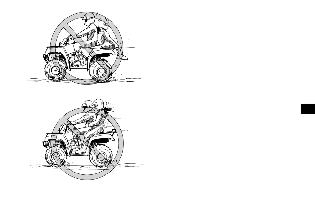
This ATV is designed to carry the operator and
cargo only – passengers prohibited.
The long seat is to allow the operator to shift position as needed during operation. It is not for carrying passengers. WARNING! Never carry a
passenger. Carrying a passenger on this ATV
greatly reduces your ability to balance and
control this ATV. You could have an accident,
resulting in severe injury or death to you
and/or your passenger.
[EWB01401]
7-3
Page 61
Apparel
Always wear the fo llowing to re duce risk o f injury in
an accident:
● Approved motorcycl e he lm et that fi ts prop er ly
● Eye protection (goggles, helmet fa ce shield, or
protective eyewear)
● Over-the-ankle boots, gloves, long-sleeved shirt
or jacket, and long pa nts
An approved he lmet and oth er pe rsona l pro tect ive
equipment can reduce the severity of injuries in an
accident. WARNING! Operating without an ap-
proved motorcycle helmet increases your
chances of a se vere he ad in jury or deat h in th e
event of an accident.
[EWB01411]
Wear eye protec tion when oper ating your AT V to
reduce the risk of a serious accident or injury. Eye
protection, su ch as a fac e shield or goggl es, may
reduce the risk of foreign materi al getting in your
eyes and help prevent loss of vision. WARNING!
Operating without eye protection can result in
an accident and increases your chance s of a
severe injury in the event of an accident.
[EWB02611]
7
7-4
Page 62

1. Protective clothing
2. Goggles
3. Gloves
4. Boots
7
5. Helmet
Do not operate after or while consuming alcohol or drugs.
The operator’s pe rformance capab ility is reduced
by the influence of alcohol or drugs. Consuming alcohol or drugs could seriously affect your judgment, cause yo u to react more s lowly, and affec t
your balance and perception. WARNING! Never
consume alcohol or drugs before or while driving this ATV. You increase your chance of an
accident.
[EWB01421]
Pre-operation checks
Always inspect your ATV each time you use it to
make sure the ATV is in safe op eratin g conditi on.
Perform the pre-operation checks listed on page
5-1. Always follow the inspection and maintenance
procedures an d schedu les descri bed in th e Owner’s Manual. WARNING! Failure to inspect the
ATV before operating it and to maintain it properly increases the possibility of an accident or
equipment damage.
[EWB01431]
Speed limiter
For riders less experienced with this model, the
throttle lever housing is eq uipped wi th a speed limiter. The speed limiter keeps the throttle from fully
7-5
Page 63

opening, even when the throttle lever is pushed to
the maximum. Turn ing in the adj usting screw lim its
the maximum engine power available and decreases the maximum speed of the ATV. Turning
in the adjustin g screw decreases to p speed, and
turning it out increases top speed. (See page 4-6.)
1. Adjusting screw
Loading and accessories
EWB01462
WARNING
Improper loading or towing can increase the
risk of loss of control, an overturn, or other accident. To reduce the risk of an accident:
● Do not exceed the maximum loading limits
for the vehicle (see “MAXIMUM LOADING
LIMIT” in this section or vehicle labeling).
● Keep weight on racks centered side to side,
and as low as possible. Be sure cargo is se-
cured – a loose load could change handling
unexpectedly.
● Make sure the load does not interfere with
your control or ability to see where you are
going.
● Tie down cargo in the trailer securely. Make
sure cargo in the trailer cannot move around.
A shifting load can cause an accident.
● Reduce speed and allow more room to stop.
A heavier vehicle takes longer to stop.
● Avoid hills and rough terrain. Choose terrain
carefully. Use extreme ca ution when towing
or carrying a load on inclines.
● Turn gradually and go slowly.
Take extra p rec auti ons w hen driv ing wi th a l oad o r
trailer. Follow these instructions and always use
common sense and go od jud gmen t when carr yin g
cargo or towing a trailer.
7
7-6
Page 64

MAXIMUM LOAD I NG LIM IT
A TV loading limit (total weight of cargo, rider,
accessories, an d t ongu e) :
210.0 kg (463 lb)
Front carrier:
40.0 kg (88 lb)
Rear carrier:
80.0 kg (176 lb)
Storage compartment:
2.0 kg (4 lb)
Trailer hitch:
Pulling load ( tota l w eight of t rai ler and c argo):
7
4900 N (500 kgf, 1102 lbf)
Tongue weight (vertical weight on tr ailer
hitch point):
147 N (15 kgf , 33 lb f )
Drive more slowly than you would wit hout a load.
The more weight you carry, the slower you should
go. Although conditions vary, it is good practice to
drive slowly (shift into first gear or low drive if available on this model) whenever you are carrying
heavier loads or when towing a trailer.
During operation
Always keep your feet on the footboards during operation; otherwise, they may contact the rear
wheels. WARNING! Removing eve n one hand
or foot can reduce your ability to control the
ATV or could cause you to lose your balance
and fall off of the ATV. If you remove a foot
from a footboard, your foot or leg may come
into contact with the rear wheels, which could
injure you or cause an accident.
[EWB01471]
Avoid wheelies and jumping. WARNING! At-
tempting wheelies, jumps, and other stunts increases the cha nce of an accident, including
7-7
Page 65

an overturn. Never attempt stunts, such as
wheelies or jumps. Don’t try to show off.
[EWB01481]
Modifications and accessories
Never modify this ATV through improper inst allation or use of accessories or other modification. All
parts and accessorie s added to this ATV should be
genuine Yamaha or equivalent components designed for use on this ATV an d should be inst alled
and used according to instructions. If you have
questions, consult an authorized ATV dealer.
WARNING! Operating this ATV with improper
modifications may cause changes in handling
which in so me sit uation s coul d lead to an ac ci-
[EWB01491]
dent.
Exhaust syst em
EWB01501
WARNING
● Dry grass or brush or other combustible ma-
terial accumulated around the engine area
could catch fire. Do not operate, idle, or park
the ATV in dry grass or other dry ground cover. Keep the engine area free of dry grass,
brush, or other combustible material.
● Someone touching the exhaust system dur-
ing or after operation could be burned. Do
not touch the hot exhaust system. Do not
park the ATV in a place where others might
be likely to touch it.
The muffler and other engine parts become extremely hot d uring ope ration and remai n hot aft er
the engine has st opped. T o reduc e the r isk of fi re
during operation or after leaving the ATV, do not let
brush, grass and other materials collect under the
vehicle, near the muffler or exhaust pipe, or next to
other hot parts. Check under the vehicle after operating in areas wh er e c om bu s tibl e m ate r ia ls may
have collect ed. Do not idle or park the v ehicle in
long dry grass or other dry ground cover.
7-8
7
Page 66

To prevent burns, avoid touching the exhaust system. Park the ATV in a place where pedestrians or
children are not li kel y to to uch it .
7
BE CAREFUL WHERE YOU RIDE
This ATV is designed for use on unpaved surfaces
only. WARNING! Paved surfaces may seriously
affect handling and control of the ATV, and
may cause the ATV to go out of control. Always
avoid paved surfaces, including sidewalks,
driveways, parking lots and streets.
[EWB01511]
While riding on unpaved public streets or roads
may be legal i n your are a, such op eration can increase the risk of collision with other vehicles.
Watch carefully for other vehicles. Make sure you
7-9
Page 67

know your country’s laws and regulations before
you ride on unpaved public streets or roads. Do not
ride on any paved publi c str eet, r oad or moto rway.
WARNING! Never operate this ATV on any
paved street, paved road or motorway. You can
collide with another vehicle.
[EWB01521]
ful when operating on unfamiliar terrain. Always be alert to changing terrain conditions
when operating the ATV.
[EWB01531]
7
Know the terrain where you ride. Ride cautiously in
unfamiliar areas. Stay alert for holes, rocks, or
roots in the terrain, and other hidden hazards
which may cause th e ATV to upset. WARNING!
The ATV could go out of control if you do not
have enough time to react to hidden rocks,
bumps, or holes. Go slowly and be extra care-
Do not operate on rough, slippery, or loose terrain
until you have learned and practiced the skills necessary to control the ATV on such terrain. Always
be especially cautious on these kinds of terrain.
WARNING! Failure to use extra care when operating on excessively rough, slippery, or
7-10
Page 68

loose terrain could cause loss of traction or
ATV control, which could result in an accident,
including an overturn.
[EWB01541]
7
When riding in an a rea w he re y ou mi gh t no t ea sil y
be seen, such as desert terrain, mount a caution
flag on the ATV. DO NOT use the flag pole bracket
as a trailer hitch. WARNING! You could collide
with another vehicle if operating in areas where
you cannot easily be seen. Mount a caution
flag on the ATV to make you more visible.
Watch carefully for other vehicles.
[EWB01551]
Do not ride in area s po ste d “no trespassing”.
Do not ride on pr ivate p rop erty w ith out gett ing p ermission.
7-11
Page 69

Select a large, flat, unpaved area to beco me fami liar with your A TV . M ak e s ure th at thi s a rea i s free
of obstacles and other riders. You should practice
control of the throttle, brakes, and turning techniques in this area before trying more difficult terrain.
Set the parking brake and follow the instruction on
page 6-1 to sta rt the engine . Once i t has warmed
up you are ready to begin riding your ATV. With the
engine idling, return the starter (choke) to the
closed positio n, and s hift the dr ive se lect lev er int o
the forward position, and then release the parking
brake. Apply the throttle slowly and smoothly.
The centrifugal clutch will engage and you will start
to accelerate. If the throttle is applied too abruptly,
the front wheels may lift off the ground, resulting in
a loss of dir ectional contro l. Avoid higher speeds
until you are thorou gh ly fam i li ar wit h the operation
of your ATV.
When slowing down or stopping, release the throttle and apply the brakes smoothly and evenly. Improper use of the brakes can cause the tires to lose
traction, reducing control and increasing the possibility of an accident.
TURNING YOUR ATV
EWB01771
WARNING
Always follow proper procedures for turning
as described in this Owner’s Manual. Prac tice
turning at low speeds before attempting to turn
at faster speeds. Do not turn at speeds too fast
for your skills or the conditions. ATV could go
out of control, causing a collision or overturn.
To achieve maxi mum t racti on on unpav ed s urfac es, the two rear wh eels tu rn togeth er at the same
speed. Therefore, unless the wheel on the inside
of the turn is allowed to slip or lose some traction ,
the ATV will resist turning. A special turning technique must be used to allow the ATV to make turns
quickly and ea sily. It is essential that this skill be
learned first at low sp ee d.
As you approach a curve, slow down and begin to
turn the handlebars in the desired direction. As you
do so, put your weight on the footboard to the outside of the turn (op posite your desired directi on)
and lean your upper body into the tu rn. Use the
throttle to maintain an even speed through the turn.
This maneuver will let the wheel on the inside of
the turn slip slightly, allowing the ATV to make the
turn properly.
7-12
7
Page 70

1. Lean towards inside of turn.
7
2. Support your weight on the outer footboard.
This procedure should be practiced at slow speed
many times in a large unpave d area w ith no obstacles. If an incorrect technique is used, your ATV
may continue to go straight. If the ATV doesn’t
turn, come to a stop a nd then p ractice the procedure again. If the r iding surface is sl ippery or loos e,
it may help to position more of your weight over the
front wheels by moving forward on the seat.
Once you have learned this te chni que, y ou should
be able to perf orm it a t high er spe eds or in ti ghter
curves.
Improper riding procedures such as abrupt throttle
changes, excessive b raki ng , i nco rrect b ody mo ve ments, or too much spee d for the sh arpness of t he
turn may cause the ATV to tip. If the ATV begins to
tip over to the outside while negotiating a turn, lean
more to the inside. It may also be necessary to
gradually let off on the throttle and steer to the outside of the turn t o av oid ti pp in g ov er.
Remember: Avoid higher speeds until you are
thoroughly familiar with the operation of your ATV.
CLIMBING UPHILL
EWB01671
WARNING
Climbing hills improperly can cause overturns
or loss of control. Use proper riding techniques described in this Owner’s Manual.
● Never operate the ATV on hills too steep for
the ATV or for your abilities. The ATV can
overturn more easily on extremely steep hills
than on level surfaces or small hills.
● Always check the terrain carefully before
you start up an y hill. Never climb hi lls with
excessively slippery or loose surfaces.
● Shift your weight forward.
● Never open the throttle suddenly. The ATV
could flip over backwards.
7-13
Page 71

● Never go over the top of any hill at high
speed. An obstacle, a sharp drop, or another
vehicle or person could be on the other side
of the hill.
● Never attempt to turn the ATV around on any
hill until you have mastered the turning technique as described in the Owner’s Manual on
level ground. Be very careful when turning
on any hill.
● Avoid crossing the side of a steep hill if pos-
sible. When crossing the side of a hill, shift
your weight to the uphill side of the ATV.
7
7-14
Page 72

Do not attemp t to climb hill s until you ha ve mastered basic maneuvers on flat ground. Always
check the terrain carefully before attempting any
hill. In all ca ses avoid incl ines with slipp ery or loose
surfaces, or obstacles that might cause you to lose
control.
To climb a hill, yo u need traction, momentum, and
steady throttle. For more traction and control for
climbing steeper and/or rougher slopes, select
“4WD”. Travel fast en ough to maintai n momentum,
but not so fast that you cannot react to changes in
the terrain as you climb.
It is important when climbing a hill to make sure
that your weight is t ransferr ed forwa rd on the AT V.
7
This can be ac compl ished by le anin g for ward and,
on steeper inclines, standing on the footboards
and leaning forwar d over the handleba rs. Whenever possible, ride straight up hills.
Slow down when you reach the crest of the hill if
you cannot see clearly what is on the other side –
there could be an other person, an obstac le, or a
sharp drop-off . Use common se nse and remem ber
that some hills are too steep for you to climb or descend.
If you are climbing a hill an d you find t hat you have
not properly ju dged your ability to make it to th e
top, you should turn the ATV aro und whi le you still
have forward motion (provided you have the room
to do so) and go down the hill.
If your ATV has stalled o r stopped and you belie ve
you can continue up the hill, restart carefully to
make sure you do not lift the front wheel s which
could cause you to lose control. If you are unable
to continue up the hill, dismount the ATV on the uphill side. Physically turn the ATV around and then
descend the hill .
If you start to roll backwards, DO NOT apply either
brake abruptly. If you are in “2WD”, apply only the
front brake. When fully stopped, apply the rear
brake as well, and the n lock the parkin g brake. If
you are in “4WD”, because all wheels are inter con-
nected by the d rive tra in , a ppl yi ng ei th er b rak e w ill
brake all wheels, therefore, avoid sudden application of either the front o r rear bra ke as th e whee ls
on the uphill si de could co me off the gr ound. The
ATV could easily tip over backwards. Apply both
the front and rear brakes gradually. When fully
stopped, lock the parking brake and dismount the
ATV immediately on the uphill side, or to a side if
pointed strai ght uphill. Turn the ATV around and
7-15
Page 73

remount, follo win g th e proc edur e d escr ibed in the
Owner’s Manual. WARNING! Stalling, rolling
backwards or improperly dismounting while
climbing a hill could result in ATV overturning.
If you cannot control the ATV, dismount immediately on the uphill side.
[EWB01802]
● Always check the terrain carefully before
you start down any hill.
● Never operate the ATV on hills too steep for
the ATV or for your abilities. The ATV can
overturn more easily on extre mely steep hil ls
than on level surfaces or small hills.
● Shift your weight backward and to the up
side of the hill.
● Never go down a hill at high speed.
● Avoid going down a hill at an angle that
would cause the ATV to lean sharply to one
side. Go straight down the hill where possible.
● Improper brak ing can cause the wheels on
the uphill side to come off the ground or
cause loss of traction. Apply brakes gradually. If in “2WD”, apply only the rear brake.
7
RIDING DOWNHILL
EWB01621
WARNING
Going down a hill improperly could cause
overturns or loss of control. Always follow
proper procedures for going down hills as described in this Owner’s Manual.
When riding y our ATV downhill, shift your weight
as far to the rear and uphill side of the ATV as possible. Move b ack on the seat and sit wit h your arms
straight. Engine compression will do most of the
braking for you. For maximum engine compression braking effect, change to “4WD” before beginning to descend th e hi ll.
7-16
Page 74

Use caution wh ile descendin g a hill with lo ose or
slippery surf aces. Braki ng ab ility and tr acti on may
be adversely affected by these surfaces. Improper
braking may also cause a loss of traction.
When this ATV is in “4WD”, all wheels (front and
rear) are interconnected by the drive train. This
means that app lying either the front br ake or the
rear brake wil l br ake al l whe els. When d escen ding
hills, using either brake lever or the brake pedal will
brake the wheels on the do wnhill side . Avo id sudden application of either the front or rear brake because the wheels on the uphill side could come off
the ground. Apply both the front and rear brakes
gradually.
7
Whenever possible, ride your ATV straight downhill. Avoid sharp angles which could allow the ATV
to tip or roll over. Carefully choose your path and
ride no faster than yo u will be abl e to rea ct to o bstacles which may appear.
CROSSING A SLOPE
EWB01632
WARNING
Improperly crossing hills or turning on hills
could cause loss of control or cause the ATV to
overturn.
● Always follow proper procedures as de-
scribed in the Owner’s Manual.
● Avoid hills with excessively slippery or loose
surfaces.
● Avoid crossing the side of a steep hill.
7-17
Page 75

● Shift your weight to the uphill side of the
ATV.
● Never attempt to turn the ATV around on any
hill until you have mastered the turning technique as described in the Owner’s Manual on
level ground. Be very careful when turning
on any hill.
Traversing a sloping surface on your ATV requires
you to properly position your weight to maintain
proper balance. Be sure that you have learned the
basic riding skil ls on flat gro und be fore attemp ting
to cross a sloping surface. Avoid slopes with slippery surfaces or rough terrain that may upset your
balance.
As you travel across a slope, lean your body in the
uphill direction. It may be necessary to correct the
steering when riding on loose surfaces by pointing
the front wheels slightly uphill. When riding on
slopes, be sur e not to ma ke shar p turns ei ther up
or down hill.
If your ATV does be gi n t o ti p o v er, g r ad ua ll y s tee r
in the downhi ll direct ion if ther e are no obstacl es in
your path. As yo u regain pro per balance , gradual ly
steer again in the direction you wish to travel.
7
CROSSING THROUGH SHALLOW WATER
EWB01641
WARNING
Operating this vehicle through deep or fastflowing water can lead to loss of control or an
overturn. To reduce your risk of drowning or
other injuries, use care when crossing through
water. Never operate this ATV water deeper
than the depth specified in your Owner’s Manual, as tires may float, increasing the risk of an
overturn.
7-18
Page 76

The ATV can be used to cross slow moving, shallow water of up to a maxi mum of 35 cm (14 in) in
depth. Before en tering the water, choose your path
carefully. Enter where there is no sharp drop of f,
and avoid rocks or other obstacles which may be
slippery or upse t the ATV. Driv e slowly and car efully.
7
Test your brakes after leaving the water. If necessary, apply them several times to let friction dry out
the linings. Do not continue to ride your ATV without verifying that you have regained proper braking
ability. WARNING! Wet brakes may have re-
duced stopping ability, which could cause loss
of control.
[EWB02621]
After riding your ATV in water, be sure to drain the
trapped water by removing the check hose at the
bottom of the air filter case, the V-belt cooling duct
check hose and the storage compartment check
hose. Also, re move the V-belt case dr ain plug to
drain any water that may have accumulated.
NOTICE: Undrained water can cause damage
or improper operation.
[ECB00841]
Wash the ATV in fresh water if it has been operated in salt water or muddy condit ions.
7-19
Page 77

1. Air filter case check hose
1. Storage compartment check hose
7
1. V-belt cooling duct check hose (left front side of ATV)
1. V-belt case drain plug
7-20
Page 78

RIDING OVER ROUGH TERRAIN
EWB01651
WARNING
Riding improperly over obstacles could cause
loss of control or a collision. Before operating
in a new area, check fo r obstacles. Never attempt to ride over large obstacles, such as
large rocks or fallen trees. When you go over
obstacles, always follow proper procedures as
described in the Owner’s Manual.
Riding over rough terrain should be done with caution. Look out for obstacles which could cause
damage to the ATV or could lead to an upset or ac-
7
cident. Be sure to keep your feet firmly mounted on
the footboards at all times. Avoid jumping the ATV
as loss of control and damage to the ATV may result.
SLIDING AND SKIDDING
EWB01662
WARNING
Skidding or sliding improperly may cause you
to lose contro l of this ATV. You may also regain traction unexpectedly, which may cause
the ATV to overturn.
● Learn to safely control skidding or sliding by
practicing at low speeds and on level,
smooth terrain.
● On extremely sli p per y su r fac es , such as ic e,
go slowly and be very cautious in order to reduce the chance of skidding or sliding out of
control.
Care should be used when riding on loose or slippery surfaces since the ATV may slide. If unexpected and uncor rected, sliding could lea d to an
accident.
To reduce the tendency for the front wheels to slide
in loose or slippery conditions, positioning your
weight over the front wheels will sometimes help.
7-21
Page 79

If the rear wheels of your ATV sta rt to slide side ways, control can usually be regained (if there is
room to do so ) by steering in the direction of the
slide. Applying the brakes or accelerating is not
recommended un til yo u ha ve corr e cted th e sli de .
With practice, ov er a period of time, skill at con trolled sliding can be developed. The terrain
should be chosen carefully before attempting such
maneuvers, since both stability and control are reduced. Bear in mind that sliding mane uvers sho uld
always be avoide d on ex tre me ly sli pp er y s ur fa ces
such as ice, since all con t rol may b e lost.
WHAT TO DO IF...
This section is designed to be a reference guide
only. Be sure to read e ach se ctio n on ridi ng tec hniques completely.
WHAT TO DO...
● If your ATV doesn’t turn when you want it to:
Bring the ATV t o a stop and practice the turning
maneuvers ag ain. Be su re you ar e puttin g your
weight on the footboard to the outside of the
turn. Position your weig ht over the fro nt wheels
for better con tr ol. ( See pa ge 7-1 2. )
● If your ATV begins to tip while turning:
Lean more into the turn to regain balance. If necessary, grad uall y le t off the t hrottl e and /or ste er
to the outside of th e tur n. (S ee pa ge 7-12 . )
● If your ATV starts to slide sideways:
Steer in the direction of the slide if you have the
room. Applying the brakes or accelerating is not
recommended until you have corrected the
slide. (See page 7-21.)
● If your ATV can’t make it up a hill you are trying
to climb:
Turn the ATV around if you still have forward
speed. If not, stop, dismount on the uphill side of
the ATV an d phys ically t urn the ATV around. If
the ATV starts to slip backwards, DO NOT USE
7-22
7
Page 80

THE REAR BRAKE IF THE ATV IS IN “2WD” –
the ATV may tip over on top of you. Dismount
the ATV on the uph ill si de. (S ee page 7 -13 .)
● If your ATV is traversing a sloping surface:
Be sure to ride with yo ur weight positioned towards the uphill side of the ATV to maintain
proper balance. If the ATV starts to tip, steer
down the hill (if ther e are no obstacles in your
way) to regain ba lance. If you discover that the
ATV is going to tip over, dismount on the uphill
side. (See page 7-17.)
● If your ATV encounters shallow water:
Ride slowly and carefully through s low moving
water, watching for obstacles. Be sure to let wa-
7
ter drain from the ATV and CHECK YOUR
BRAKES FOR PROPER OPERATION when
you come out of the water. Do not continue to
ride your ATV unti l you ha ve rega ined adeq uate
braking abili ty . ( Se e p age 7-18.)
7-23
Page 81

EBU28783
PERIODIC MAINTENANCE AND ADJUSTMENT
EBU21674
Periodic inspection, adjustment, and lubrication
will keep your v ehicle in the safe st and most effi cient condition possible. Safety is an obligation of
the vehicle owner/operator. The most important
points of vehicle inspection, adjustment, and lubrication are explained on the following pages.
EWB01841
WARNING
Failure to properly maintain the vehicle or performing maintenance activities incorrectly may
increase your risk of injury or death during service or while using the vehicle. If you are not familiar with vehicle service, have a Yamaha
dealer perf or m t he se rv ic e.
EWB02562
WARNING
Turn off the engine when performing maintenance unless otherwise specified.
● A running engine has moving parts that can
catch on body parts or clothing and electrical parts that can cause shocks or fires.
● Running the engine while servicing can lead
to eye injury, burns, fire, or carbon monoxide
poisoning - possibly leading to death. See
page 2-3 for more information about carbon
monoxide.
EWB02690
WARNING
Brake discs, calipers, drums, and linings can
become very hot during use. To avoid possible
burns, let brake components cool before
touching them.
The intervals given in the periodic maintenance
charts should be considered as a general guide
under normal riding conditions. However, DEPENDING ON THE WEATHER, TERRAIN, GEOGRAPHICAL LOCATION, AND INDIVIDUAL
USE, THE MAINTENANCE INTERVALS MAY
NEED TO BE SHORTENED.
8
8-1
Page 82

EBU21731
Owner’s manual and tool kit
Be sure to put th is owner’s manual in the plastic
bag and always c arry it on the bottom o f the seat
as shown. Put th e owner’s tool kit and low-pr essure tire gauge un de r th e se at .
8
1. Owner’s manual
2. Owner’s tool kit
3. Low-pressure tire gauge
The service information included in this manual
and the tools provided in the owner ’s tool kit are intended to assist you i n the perf ormance of preventive maintenance and minor repairs. However,
additional tools such as a torque wrench may be
necessary to perform certain maintenance work
correctly.
TIP
If you do not ha ve th e to ols or experi en ce req uired
for a particular job, have a Yamaha dealer perform
it for you.
8-2
Page 83

EBU21743
Periodic maintenance chart f or t he emis sion c ontrol system
TIP
● For ATVs not equi pped wit h an o dome te r or an hour me t er, fo llow th e mo nt h main t en an ce in t erva ls.
● For ATVs equi pped with an o dome te r or an hour me ter , foll ow th e km (m i) o r hour s ma inte nance i nter -
vals. However, ke ep in min d th at if th e ATV is n ’t used for a long period of time, the month maintenance
intervals should be f ollow ed .
● Items marked with an asterisk should be performed by a Yamaha dealer as they require special tools,
data and techni cal skill s.
INITIAL EVERY
NO. ITEM
1 * Fuel line
2 Spark plug
3 * Valves • C heck valve clearance and adjust if necessary. √ √√√
4 * Carburetor
Crankcase breather
5 *
system
CHECK OR MAINTENANCE
JOB
• Check fuel hoses for cracks or other damage, and
replace if necessary.
• Check condition and clean, regap, or replace if
necessary.
• Check starter (choke) operation and correct if necessary.
• Check engine idling speed and adjust if necessary.
• Check breather hose for cracks or other damage,
and replace if necessary.
Whichever comes
first
month136612
km
(mi)
hours 20 80 160 160 320
320
(200)
1300
(800)
√√√√√
2500
(1600)
√√√√
2500
(1600)
√√√
√√√
5000
(3200)
8
8-3
Page 84

INITIAL EVERY
NO. ITEM
6 * Exhaust system
7 Spark arrester • Clean. √√√
CHECK OR MAINTENANCE
JOB
• Check for leakage and replace gasket(s) if necessary.
• Check for looseness and tighten all screw clamps
and joints if necessary.
Whichever comes
first
month136612
km
320
(mi)
(200)
hours 20 80 160 160 320
1300
(800)
2500
(1600)
2500
(1600)
√√√
8
5000
(3200)
8-4
Page 85

EBU21865
General maintenance and lubrication chart
TIP
● For ATVs not equi pped wit h an o dome te r or an hour me t er, fo llow th e mo nt h main t en an ce in t erva ls.
● For ATVs equi pped with an o dome te r or an hour me ter , foll ow th e km (m i) o r hour s ma inte nance i nter -
vals. However, ke ep in min d th at if th e ATV is n ’t used for a long period of time, the month maintenance
intervals should be f ollow ed .
● Items marked with an asterisk should be performed by a Yamaha dealer as they require special tools,
data and techni cal skill s.
INITIAL EVERY
NO. ITEM
1 Air filter element • Clean and replace if necessary.
2 * Front brake
3 * Rear brake
CHECK OR MAINTENANCE
JOB
• C heck operation and correct if necessary.
• C heck fluid level and ATV for fluid leakage, and
correct if necessary.
• R eplace brake pads. Whenever worn to the limit
• C heck operation and correct if necessary.
• C heck brake lever and pedal free play, and adjust
if necessary.
• R eplace brake shoes. Whenever worn to the limit
Whichever comes
first
month136612
km
(mi)
hours 20 80 160 160 320
320
(200)
Every 20–40 hours (more often in wet or
1300
(800)
√√√√√
√√√√√
2500
(1600)
dusty areas)
2500
(1600)
5000
(3200)
8
8-5
Page 86

INITIAL EVERY
NO. ITEM
4 * Brake hoses
5 * Wheels
6 * Tires
7 * Wheel hub bearings
8
8 * Swingarm • Check for excessive play, and correct if necessary. √√√
9 * V-belt
10 * Chassis fasteners
11 *
12 * Steering shaft • Lubricate with lithium-soap-based grease. √√√
13 * Steering system
Shock absorber assemblies
CHECK OR MAINTENANCE
JOB
• Check for cracks or other damage, and replace if
necessary.
• Replace. Every 4 years
• Check runout and for damage, and replace if nec-
essary.
• Check tread depth and for damage, and replace if
necessary.
• Check air pressure and balance, and correct if
necessary.
• Check for looseness or damage, and replace if
necessary.
• Check for wear, cracks or other damage, and replace if necessary.
• Make sure that all nuts, bolts, and screws are
properly tightened.
• Check operation and correct if necessary.
• Check for oil leakage and replace if necessary.
• Check operation and repair or replace if damaged.
• Check toe-in and adjust if necessary.
Whichever comes
first
month136612
km
320
(mi)
(200)
hours 20 80 160 160 320
1300
(800)
√ √√√
√ √√√
√ √√√
√ √√√
√√√√√
√√√√√
2500
(1600)
√√√√
2500
(1600)
√√√
5000
(3200)
8-6
Page 87

NO. ITEM
14 * Engine mount
15 * Axle boots
16 Engine oil
17
18 Differential gear oil
19 Final gear oil
20 *
21 *
22 * Throttle lever
Engine oil filter cartridge
Moving parts and
cables
Drive select lever
safety system cable
INITIAL EVERY
CHECK OR MAINTENANCE
JOB
• C heck for cracks or other damage, and replace if
necessary.
• C heck for cracks or other damage, and replace if
necessary.
• C hange.
• Check ATV for oil leakage, and correct if neces-
sary.
• R eplace. √√√
• C hange.
• Check ATV for oil leakage, and correct if neces-
sary.
• C hange.
• Check ATV for oil leakage, and correct if neces-
sary.
• Lu bricate. √√√√
• C heck operation and adjust or replace if neces-
sary.
• Check operation.
• C heck throttle lever free play, and adjust if neces-
sary.
• Lubricate cable and lever housing.
Whichever comes
first
8-7
month136612
km
(mi)
hours 20 80 160 160 320
320
(200)
1300
(800)
√√√√√
√ √√√
√√
√√
√√√√√
2500
(1600)
2500
(1600)
√√√
√√√
5000
(3200)
8
Page 88

INITIAL EVERY
month136612
km
320
(mi)
(200)
hours 20 80 160 160 320
1300
(800)
√√√√√
2500
(1600)
2500
(1600)
NO. ITEM
23 *
24 * Lights and switches
EBU28391
Front and rear brake
switches
CHECK OR MAINTENANCE
JOB
• Check operation and correct if necessary. √√√√√
• Check operation and correct if necessary.
• Adjust headlight beams.
Whichever comes
first
TIP
● Some maintenance items need more frequent service if you are riding in unusually wet, dusty, sandy or
muddy areas, or at full-throttle.
8
● Hydraulic brake service
• Regularly check and, if necessary, correct the brake fluid level.
• Every two years replace t he internal compo nents of the brake master cylinder and calipers, a nd change
the brake fluid .
• Replace the brake hoses ever y fo ur ye ars a nd if cra cke d or dam ag ed .
5000
(3200)
8-8
Page 89

EBU23213
Checking the spark plug
The spark plu g is a n imp ortan t en gine compon ent,
which is easy to c heck. Since heat and dep osits
will cause any spark plug to slowly erode, the spark
plug should be removed and checked in accordance with the periodic maintenan ce and l ubrication chart. In ad dition, the condition of th e spark
plug can reveal the condition of the engine.
To remove the spark plug
1. Remove the spark plug cap.
1. Spark plug cap
2. Remove the spark plug as shown, with the
spark plug wrench included in the owner’s tool
kit.
1. Spark plug wrench
8
To check the spark plug
1. Check that the porcel ain i nsula tor a rou nd the
center electrode of the spark plug is a medium-to-light ta n (the ideal c olor when th e ATV
is ridden normally).
8-9
Page 90

TIP
If the spark pl ug show s a dis tinctly differe nt col or,
the engine coul d be operat ing improperl y. Do not
attempt to diagnose such problems yourself. Instead, have a Yam ah a de al er ch eck the ATV.
2. Check the spark plug for electrode erosion
and excessive carbon or other deposits, and
replace it if necessary.
Specified spark plug:
NGK/DR8EA
3. Measure the spark plug gap with a wire thickness gauge an d, if nece ssa ry, a djust t he gap
8
to specificatio n.
1. Spark plug gap
Spark plug gap:
0.6–0.7 mm (0.024–0.028 in)
To install the spark plug
1. Clean the surface of the spark plug gasket
and its matin g su rface , and th en wi pe off any
grime from the spark plug threads.
2. Install the spark plug with the spark plug
wrench, and then tighten it to the specified
torque.
8-10
Page 91

Tightening torque:
Spark plug:
18 Nm (1.8 m·kgf, 13 ft·lbf)
TIP
If a torque w rench i s not availa ble wh en ins talling
the spark plug, a good estimate of the correct
torque is 1/4 –1/2 turn past finger tight. Howeve r,
the spark plug should be tightened to the specified
torque as soon as possible.
3. Install the spark plug cap.
EBU23319
Engine oil and oil filter cartridge
The engine oil level should be checked before
each ride. In add ition, the oil must be change d and
the oil filt er cartridg e replaced at the interva ls specified in the periodic maintenance and lubrication
chart.
To check the engine oil level
1. Place the ATV on a level surface.
2. Check the engine oil level on a cold engine.
TIP
If the engine wa s started before chec king the oil
level, be sure to warm up the engine sufficiently,
and then wait at least ten minutes until the oil settles for an acc u ra te rea din g.
3. Remove the engine oil filler cap, and then
wipe the engine oil dipstick off with a clean
rag.
8
1. Engine oil filler cap
4. Insert the dipstick into the filler hole ( without
screwing it in), and then remove it again to
check the oil level.
8-11
Page 92

TIP
The engine oil should be between the tip of the dipstick and the maximum lev el mark.
8
1. Engine oil dipstick
2. Ma ximum level mark
3. Tip of the engine oil dipstick
To change the engine oil (with or without oil filter cartridge replacement)
1. Place t he AT V on a le vel surf ace .
2. Start the engine, warm it up for several minutes, and then t urn it off .
3. Place an oil pan un der the engine to col lect
the used oil.
4. Remove the engine o il f ill er c a p, and then remove the engine oil dra in bolt and its gasket to
drain the oil from the crankcase.
1
2
5. If the engine oil is not between th e tip of the
dipstick and the maximum level mark, add
sufficient oil of the recommended type to raise
it to the correct level. NOTICE: Be sure the
engine oil is at the correct level, otherwise
engine damage may result.
[ECB00851]
6. Insert the dipstick into the oil filler hole, and
then tighten t he en gin e o il f ill er ca p.
1
1. Engine oil drain bolt
2. Gasket
8-12
Page 93

TIP
Skip steps 5–7 if the oil filter cartridg e is not being
replaced.
5. Remove the oil filter c artri dge w ith an oil filter
wrench.
1
1
1. Oil filter wrench
TIP
An oil filter wrenc h is available at a nearb y Yamaha
dealer.
8
1. Oil filter cartridge
6. Apply a thin coat of engine oil to the O-ring of
the new oil filter cartridge.
TIP
Make sure that the O-ring is properly seated.
8-13
Page 94

1
1. O-ring
7. Install the new oil filter cartridge with an oil filter wrench, and then tighten it to the specified
torque with a torque wrench.
8
1. Torque wrench
Tightening torque:
Oil filter cartridge:
17 Nm (1.7 m·kgf, 12 ft·lbf)
8. Install the engine oil drain bolt and its new
gasket, and t he n tigh ten the bolt to the s pe c ified torque.
Tightening torque:
Engine oil drain bolt:
23 Nm (2.3 m·kgf, 17 ft·lbf)
8-14
Page 95

9. Refill with the speci fied am ount of the recom mended engine oil, and then in sta ll an d tigh ten the engine oil filler cap.
Recommended oil:
See page 10-1.
Oil quantity:
Without oil fi l te r cartridge re pl ac em en t:
2.20 L (2.33 US qt , 1 .9 4Imp.qt)
With oil filter cartridge replacement:
2.30 L (2.43 US qt , 2 .0 2Imp.qt)
TIP
Be sure to wipe off spilled oil on any parts after the
engine and exhaust system have cooled down.
ECB00300
NOTICE
● In order to prevent clutch slippage (since the
engine oil also lubricates the clutch), do not
mix any chemical add itives. Do not us e oils
with a diesel specification of “CD” or oils of
a higher quality than specified. I n addition,
do not use oils labeled “ENERGY CONSERVING II” or higher.
● Make sure that no foreign material enters the
crankcase.
10. St art th e engin e, and th en let i t idle f or sever al
minutes while checking it for oil leakage. If oil
is leaking, im mediat ely tu rn the engine off and
check for the cause.
11. Turn the engine off, wait at least ten minutes,
and then check the oi l level and correct it if
necessary.
EBU23386
Final gear oil
The final gear case must be checked for oil leakage before each ride. If any leakage is found, have
a Yamaha dealer check and repair the ATV. In addition, the fi nal ge ar oil leve l must be che cke d an d
the oil changed a s follows at th e intervals sp ecified
in the periodic maintenance and lubrication chart.
To check the final gear oil level
1. Place the ATV on a level surface.
2. Remove the final gear oil filler bolt and its gasket, and then check the oil level in the final
gear case. The oi l le v el s ho ul d be at the brim
of the filler hole.
8
8-15
Page 96

1 2
3
4
1. Final gear oil filler bolt
2. Gasket
3. Final gear oil
4. Correct oil level
8
3. If the oil is below the brim of the filler hole, add
sufficient oil of the recommended type to raise
it to the correct level.
4. Chec k the gasket for damage, a nd replac e it if
necessary.
5. Inst all th e oil f iller bo lt and its gaske t, an d then
tighten the bo lt to t he spe cif ied t orq ue .
Tightening torque:
Final gear oil filler bo lt :
23 Nm (2.3 m·kgf, 17 ft·lbf)
To change the final gear oil
1. Place t he AT V on a le vel surf ace .
2. Remove the final gear case guard by removing the bolts.
1. Final gear case guard
2. Bolt
3. Place an oil pan under the final gear case to
collect the used oil.
4. Remove the final gear oil filler bolt, the final
gear oil drai n bolt, and t heir gaske t to drain t he
oil from the final gear case.
8-16
Page 97

1 2
3
4
2
1
1. Final gear oil drain bolt
2. Gasket
5. Install the drain b olt and its new gasket, and
then tighten the bolt to the specified torque.
Tightening torque:
Final gear oil dr a in bo lt :
23 Nm (2.3 m·kgf, 17 ft·lbf)
6. Refill with the recommen ded final gear oil to
the brim of th e fille r ho le as s hown . NOTICE:
Be sure no foreign material enters the final
gear case.
[ECB00421]
1. Final gear oil filler bolt
2. Gasket
3. Final gear oil
4. Correct oil le vel
Recommended fin al gea r oil :
See page 10-1.
7. Check the oil filler bolt gasket for damage, and
replace it if necessary.
8. Insta ll the oil fil ler bolt and its gask et, and the n
tighten the bolt to the specified torque.
Tightening torque:
Final gear oil fill er bolt :
23 Nm (2.3 m·kgf, 17 ft·lbf)
8-17
8
Page 98

9. Chec k t he fi na l gea r case f o r oi l l eak ag e. I f oil
is leaking, check for the cause.
10. Install the final gea r case guard by install ing
the bolts a nd tigh teni ng th em t o t he spe cif ied
torque.
Tightening torque:
Final gear case guard bolt:
16 Nm (1.6 m·kgf, 12 ft·lbf)
EBU23436
Changing the differential gear oil
The differential gear case must be checked for oil
leakage before each ride. If any leakage is found,
have a Yamaha dealer check an d repa ir the AT V.
In addition, the differential gear oil must be
8
changed as f ol lo ws at t he i nt erv als sp ec if ied in the
periodic mainte na nc e an d lu bri c ati on cha rt.
1. Place the ATV on a level surface.
2. Place an oil pan under the differential gear
case to collect the used oil.
3. Remove the differential gear oil filler bolt, the
differential gear oil drain bolt and their gasket
to drain the oil from the differential gear case.
2
1
1. Differential gear oil filler bolt
2. Gasket
2
1
1. Differential gear oil drain bolt
2. Gasket
8-18
Page 99

4. Install the drain b olt and its new gasket, and
then tighten the bolt to the specified torque.
Tightening torque:
Diffe ren t ial ge ar oi l dr a in bol t:
10 Nm (1.0 m·kgf, 7.2 ft·lbf)
5. Refill with the speci fied am ount of the recom mended differential gear oil. NOTICE: Be
sure no foreign material enters the differential gear case.
[ECB00411]
6. Check the oil filler bolt gasket for damage, and
replace it if necessary.
7. Insta ll the oil fil ler bolt and its gask et, and the n
tighten the bolt to the specified torque.
Tightening torque:
Differ en ti al gear oi l fi lle r bo lt :
23 Nm (2.3 m·kgf, 17 ft·lbf)
8. Check the differential gear case for oil leakage. If oil is leaking, check for the cause.
TIP
● Do not exceed the sp ecified differe ntial g ear oil
quantity when f illin g. Ove rfill ing w ill ca use t he oil
to seep out of the breather hose during and after
riding.
● The differential gear case capacity is greater
than the recommended oil quantity, therefore
the oil leve l cann ot be ac cura tely che cked from
the oil filler hole.
Recommended differential gear oil:
See page 10-1.
Oil quantity:
0.35 L (0.37 US qt, 0.31 Imp.qt)
EBU23646
Cleaning the air filter e lem ent
The air filter elem ent should be cleaned at th e intervals speci fied in the peri odic maintena nce and
lubrication chart. Clean or, if necessary, replace
the air filter element more frequently if you are
riding in unus ua lly wet or dust y ar ea s.
TIP
There is a check hose at the bottom of the air filter
case. If dust or wa ter collects i n this hose, emp ty
the hose and clean the air filter element and air filter case.
8-19
8
Page 100

1. Air filter case check hose 1. Air filter case cover holder
1. Place the ATV on a level surface.
2. Remove the seat. (See page 4-13.)
3. Remo ve the a ir filte r case cove r by un hooking
8
the air filter case cover holders.
2. Air filter case cover
4. Pull the air filter element out of the air filter
case.
8-20
 Loading...