


YFM35FAS
YFM350FAS
5UH2-AE1
SUPPLEMENTARY
SERVICE MANUAL


FOREWORD
This Supplementary Service Manual has been prepared to introduce new service and data for the
YFM35FAS/YFM350FAS. For complete service information procedures it is necessary to use this
Supplementary Service Manual together with the following manual.
YFM4FAR/YFM400FAR SERVICE MANUAL: 5TE2-AE1
YFM35FAS/YFM350FAS
SUPPLEMENTARY
SERVICE MANUAL
©2003 by Yamaha Motor Co., Ltd.
First edition, July 2003
All rights reserved.
Any reproduction or unauthorized use
without the written permission of
Yamaha Motor Co., Ltd.
is expressly prohibited.

EB001000
NOTICE
This manual was produced by the Yamaha Motor Company primarily for use by Yamaha dealers
and their qualified mechanics. It is not possible to include all the knowledge of a mechanic in one
manual, so it is assumed that anyone who uses this book to perform maintenance and repairs on
Yamaha machine has a basic understanding of the mechanical ideas and the procedures of
machine repair. Repairs attempted by anyone without this knowledge are likely to render the
machine unsafe and unfit for use.
Yamaha Motor Company, Ltd. is continually striving to improve all its models. Modifications and
significant changes in specifications or procedures will be forwarded to all authorized Yamaha
dealers and will appear in future editions of this manual where applicable.
OTE:
Designs and specifications are subject to change without notice.
IMPORTANT INFORMATION
Particularly important information is distinguished in this manual by the following notations.
The Safety Alert Symbol means ATTENTION! BECOME ALERT! YOUR
SAFETY IS INVOLVED!
WARNING
CAUTION:
NOTE:
Failure to follow WARNING instructions could result in severe injury or death
to the machine operator, a bystander or a person inspecting or repairing the
machine.
A CAUTION indicates special precautions that must be taken to avoid
damage to the machine.
A NOTE provides key information to make procedures easier or clearer.
EB002000
HOW TO USE THIS MANUAL
MANUAL ORGANIZATION
This manual consists of chapters for the main categories of subjects. (See “Illustrated symbols”)
1st title 1: This is the title of the chapter with its symbol in the upper right corner of each page.
2nd title 2: This title indicates the section of the chapter and only appears on the first page of each
section. It is located in the upper left corner of the page.
3rd title 3: This title indicates a sub-section that is followed by step-by-step procedures
accompanied by corresponding illustrations.
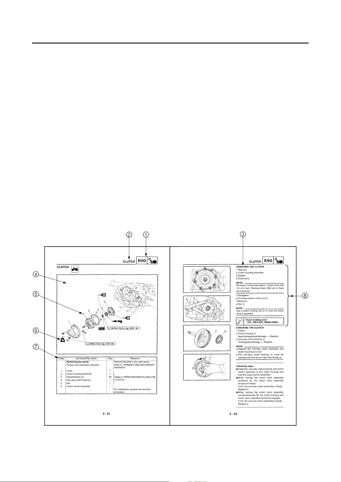
EXPLODED DIAGRAMS
To help identify parts and clarify procedure steps, there are exploded diagrams at the start of each
removal and disassembly section.
1. An easy-to-see exploded diagram 4 is provided for removal and disassembly jobs.
2. Numbers 5 are given in the order of the jobs in the exploded diagram. A number that is enclosed
by a circle indicates a disassembly step.
3. An explanation of jobs and notes is presented in an easy-to-read way by the use of symbol marks
6
. The meanings of the symbol marks are given on the next page.
4. A job instruction chart 7 accompanies the exploded diagram, providing the order of jobs, names
of parts, notes in jobs, etc.
5. For jobs requiring more information, the step-by-step format supplements 8 are given in addition
to the exploded diagram and the job instruction chart.
12
GEN
INFO
34
SPEC
CHK
ENG
ADJ
56
COOL
78
CARB
EB003000
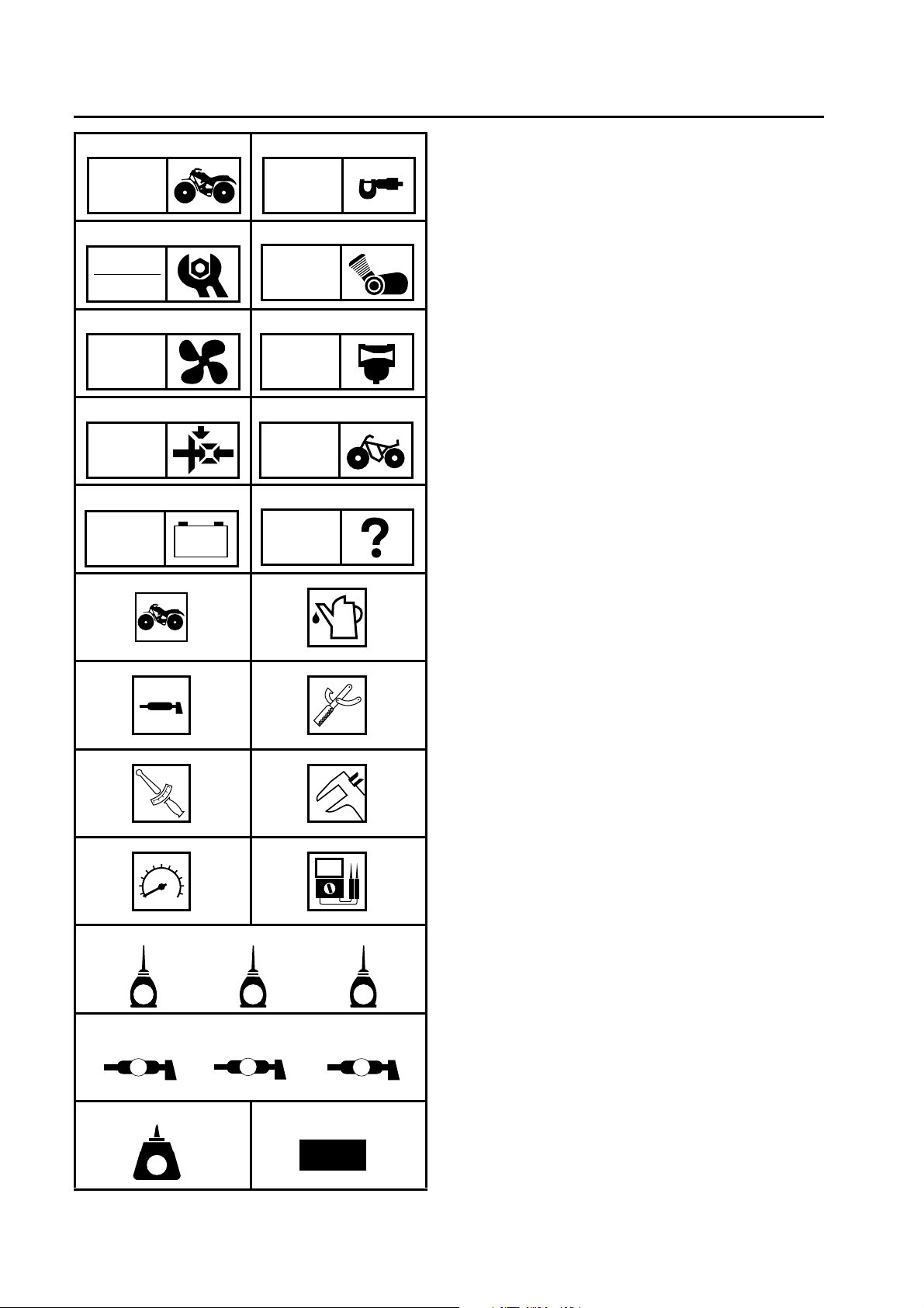
ILLUSTRATED SYMBOLS
Illustrated symbols 1 to 0 are printed on the
top right of each page and indicate the subject
of each chapter.
General information
1
Specifications
2
Periodic checks and adjustments
3
Engine
4
Cooling system
5
Carburetion
6
Drive train
7
Chassis
8
Electrical
9
Troubleshooting
0
DRIV
90
–+
ELEC
AB
CD
EF
T
.
R
.
GH
CHAS
TRBL
SHTG
Illustrated symbols A to H are used to identify
the specifications appearing in the text.
Can be serviced with engine mounted
A
Filling fluid
B
Lubricant
C
Special tool
D
Torque
E
Wear limit, clearance
F
Engine speed
G
, V, A
Ω
H
IJK
LS
G
M
M
New
E
LMN
B
OP
LT
Illustrated symbols I to N in the exploded
diagrams indicate the types of lubricants and
lubrication points.
Apply engine oil
I
Apply gear oil
J
Apply molybdenum disulfide oil
K
Apply wheel bearing grease
L
Apply lithium-soap-based grease
M
Apply molybdenum disulfide grease
N
Illustrated symbols O to P in the exploded
diagrams indicate where to apply a locking
agent O and when to install a new part P.
®
Apply the locking agent (LOCTITE
O
Replace
P
)

CONTENTS
GENERAL INFORMATION
SPECIAL TOOLS ......................................................................................1
SPECIFICATIONS
GENERAL SPECIFICATIONS ..................................................................2
MAINTENANCE SPECIFICATIONS .........................................................5
ENGINE ................................................................................................5
CHASSIS ............................................................................................15
ELECTRICAL ......................................................................................19
LUBRICATION POINTS AND LUBRICANT TYPES ...............................21
ENGINE ..............................................................................................21
OIL FLOW DIAGRAMS ...........................................................................22
CABLE ROUTING ...................................................................................26
PERIODIC CHECKS AND ADJUSTMENTS
INTRODUCTION .....................................................................................34
PERIODIC MAINTENANCE/LUBRICATION ...........................................34
SEAT, CARRIERS, FENDERS AND FUEL TANK ..................................36
SEAT, FRONT CARRIER, FRONT BUMPER AND
FRONT FENDER ................................................................................36
FUEL TANK ........................................................................................38
ENGINE ...................................................................................................39
CHECKING THE OIL TEMPERATURE WARNING LIGHT ................39
ENGINE
CYLINDER HEAD ...................................................................................40
CAMSHAFT, ROCKER ARMS AND VALVES ........................................42
CYLINDER AND PISTON .......................................................................44
RECOIL STARTER AND A.C. MAGNETO ............................................45
BALANCER GEARS AND OIL PUMP .....................................................47
OIL PUMP ...........................................................................................49
REMOVING THE BALANCER DRIVE GEAR AND
BALANCER DRIVEN GEAR ...............................................................50
REMOVING THE BALANCER DRIVE GEAR AND
BUFFER BOSS ...................................................................................50
CHECKING THE OIL PUMP DRIVEN GEAR .....................................50
CHECKING THE BALANCER DRIVE GEAR AND
BALANCER DRIVEN GEAR ...............................................................50
INSTALLING THE BALANCER DRIVE GEAR AND
BALANCER DRIVEN GEAR ...............................................................51

OIL COOLER ..........................................................................................52
PRIMARY AND SECONDARY SHEAVES ..............................................54
PRIMARY SLIDING SHEAVE .............................................................56
SECONDARY SHEAVE ......................................................................57
ASSEMBLING THE PRIMARY SHEAVE ............................................58
ASSEMBLING THE SECONDARY SHEAVE .....................................58
CLUTCH ..................................................................................................60
CRANKCASE ..........................................................................................62
STARTER MOTOR, TIMING CHAIN AND OIL FILTER .....................62
CRANKCASE ......................................................................................64
CRANKCASE BEARINGS ..................................................................65
SEPARATING THE CRANKCASE .....................................................66
ASSEMBLING THE CRANKCASE .....................................................66
CRANKSHAFT ........................................................................................68
REMOVING THE CRANKSHAFT .......................................................69
INSTALLING THE CRANKSHAFT ......................................................69
TRANSMISSION .....................................................................................70
INSTALLING THE TRANSMISSION ...................................................71
MIDDLE GEAR ........................................................................................72
MIDDLE DRIVE SHAFT ......................................................................72
MIDDLE DRIVEN SHAFT ...................................................................73
SELECTING THE MIDDLE DRIVE AND DRIVEN GEAR SHIMS ......75
DRIVE TRAIN
FRONT CONSTANT VELOCITY JOINTS AND
DIFFERENTIAL GEAR ............................................................................79
MEASURING AND ADJUSTING THE DIFFERENTIAL
GEAR LASH ........................................................................................81
CHASSIS
REAR BRAKE .........................................................................................83
CHECKING THE REAR BRAKE .........................................................85
INSTALLING THE REAR BRAKE .......................................................86
STEERING SYSTEM ..............................................................................89
STEERING STEM ...............................................................................89
FRONT ARMS AND FRONT SHOCK ABSORBERS .............................91
ELECTRICAL
ELECTRIC STARTING SYSTEM ............................................................93
STARTER MOTOR .............................................................................93
ASSEMBLING THE STARTER MOTOR ............................................94
SIGNAL SYSTEM ...................................................................................95
CIRCUIT DIAGRAM ............................................................................95
COOLING SYSTEM ................................................................................99
CIRCUIT DIAGRAM ............................................................................99
TROUBLESHOOTING .....................................................................100

TROUBLESHOOTING
FAULTY GEAR SHIFTING ....................................................................104
HARD SHIFTING ..............................................................................104
SHIFT LEVER DOES NOT MOVE ....................................................104
JUMPS OUT OF GEAR ....................................................................104
OVERHEATING ....................................................................................104
OVERHEATING ................................................................................104
FAULTY BRAKE ...................................................................................105
POOR BRAKING EFFECT ...............................................................105
YFM35FAS/YFM350FAS WIRING DIAGRAM

GEN
SPECIAL TOOLS
GENERAL INFORMATION
EB102001
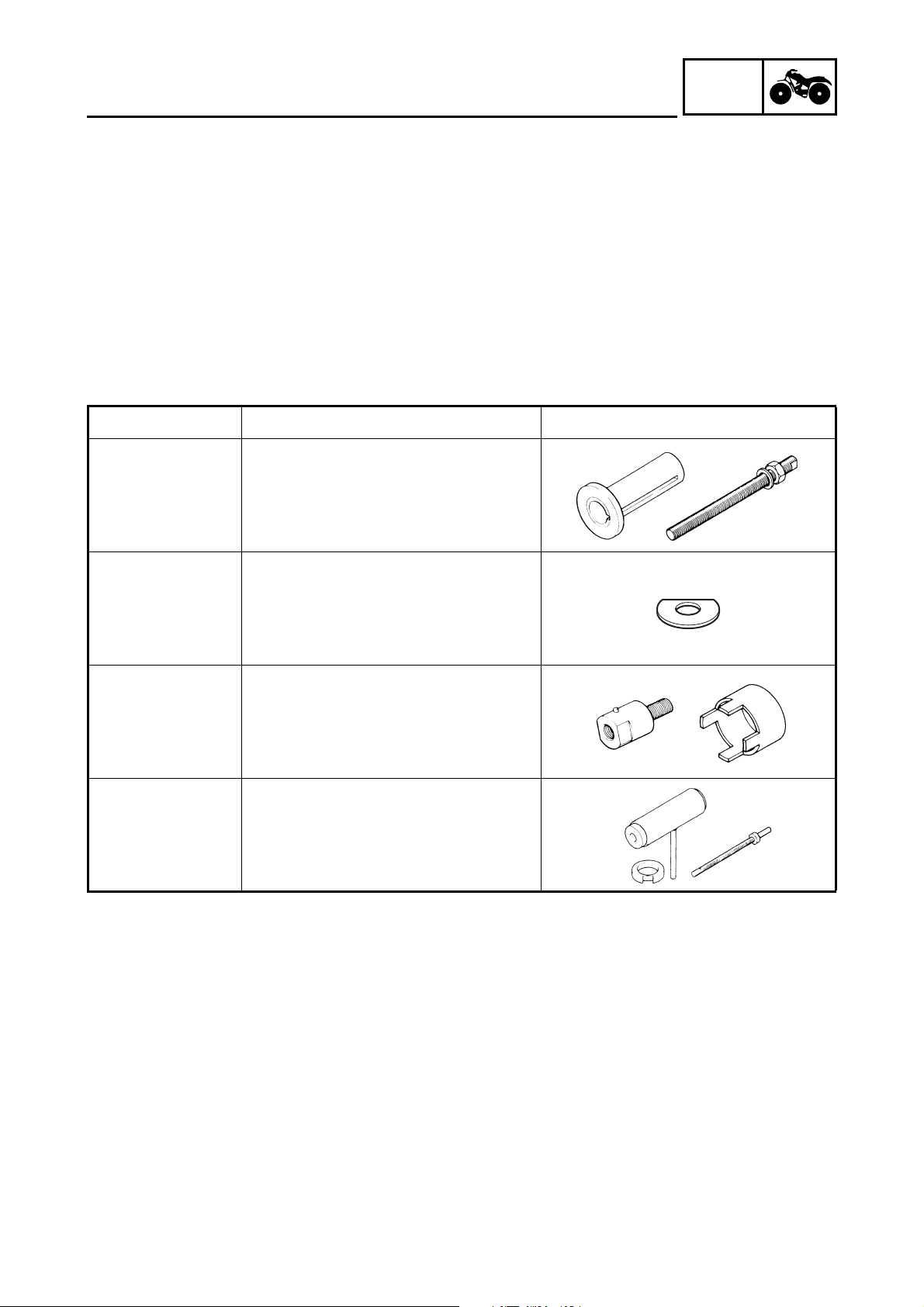
SPECIAL TOOLS
The following special tools are necessary for complete and accurate tune-up and assembly. Use
only the appropriate special tools; this will help prevent damage caused by the use of inappropriate
tools or improvised techniques. Special tools may differ by shape and part number from country to
country. In such a case, two types are provided.
When placing an order, refer to the list provided below to avoid any mistakes.
For US and CDN
P/N. YM-, YU-, YS-, YK-, ACC-
Except for US and CDN
P/N. 90890-
Tool No. Tool name/How to use Illustration
Crankshaft installer pot
Pot
90890-01274
Bolt
90890-01275
Crankshaft installer bolt
These tools are used to install the
crankshaft.
INFO
90890-01309
Adapter
90890-01383
YM-1383
Spacer
90890-04081
YM-91044
YU-90050
Spacer
This tool is used to install the
crankshaft.
Adapter
Spacer (crankshaft installer)
These tools are used to install the
crankshaft.
Crankshaft installer set
These tools are used to install the
crankshaft.
– 1 –
GENERAL SPECIFICATIONS
SPECIFICATIONS
GENERAL SPECIFICATIONS
Item Standard
Model code: 5UH2 (for CDN)
5UH4 (for Europe)
5UH5 (for Oceania)
Dimensions:
Overall length 1,984 mm (78.1 in)
Overall width 1,085 mm (42.7 in)
Overall height 1,120 mm (44.1 in)
Seat height 827 mm (32.6 in)
Wheelbase 1,233 mm (48.5 in)
Minimum ground clearance 245 mm (9.7 in)
Minimum turning radius 3,000 mm (118.1 in)
Basic weight:
With oil and full fuel tank 258 kg (569 lb)
Engine:
Engine type Air-cooled 4-stroke, SOHC
Cylinder arrangement Forward-inclined single cylinder
Displacement 348 cm
Bore × stroke 83.0 × 64.5 mm (3.27 × 2.54 in)
Compression ratio 9.2 : 1
Standard compression pressure (at sea level) 1,050 kPa (10.5 kg/cm
Starting system Electric and recoil starter
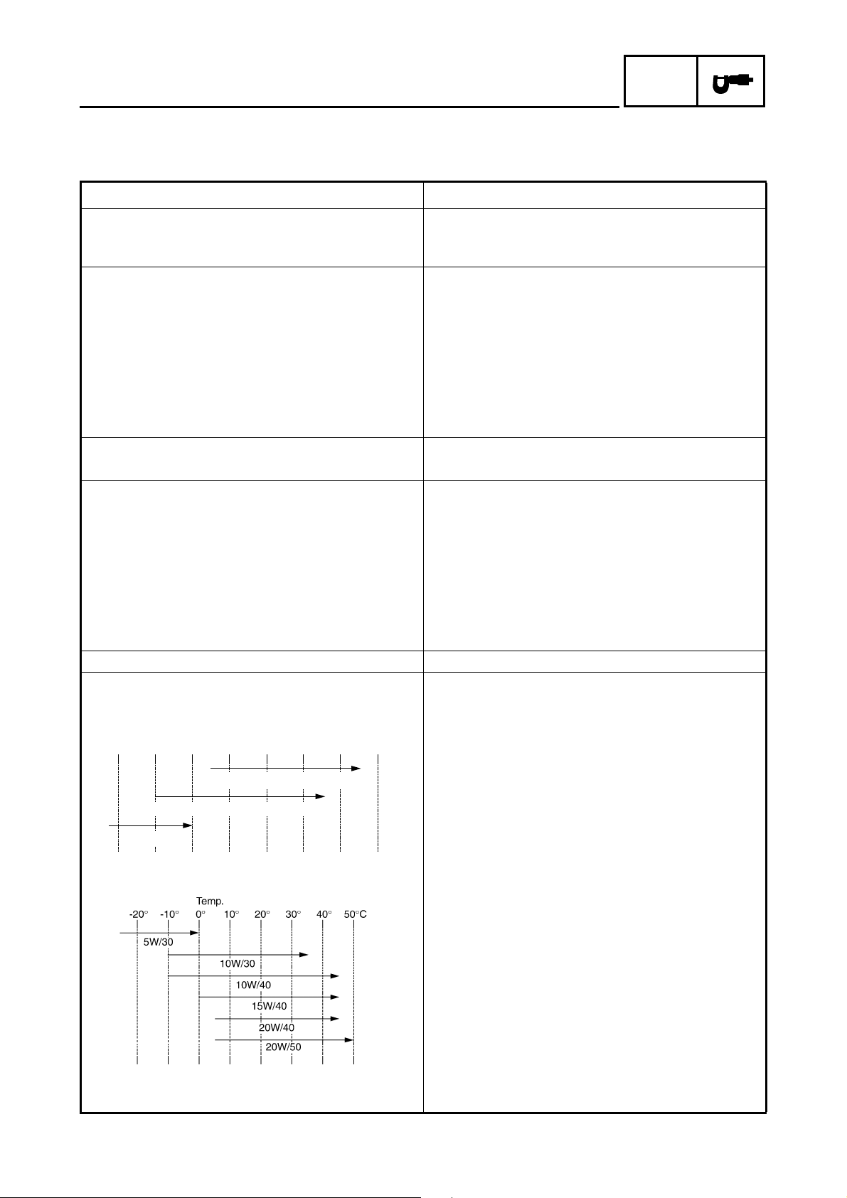
Lubrication system: Wet sump
Oil type or grade:
Engine oil
For CDN
0° 10° 30° 50° 70° 90° 110°
130°F
API service SE, SF, SG type or higher
3
2
SPEC
, 149.3 psi) at 750 r/min
YAMALUBE 4 (20W40) or SAE 20W40
YAMALUBE 4 (10W30) or SAE 10W30
SAE 5W30
-20° -10° 0° 10° 20° 30° 40°
50°C
For Europe, Oceania
Final gear oil SAE 80API “GL-4” Hypoid Gear Oil
Differential gear oil SAE 80API “GL-4” Hypoid Gear Oil
– 2 –

GENERAL SPECIFICATIONS
Item Standard
Oil capacity:
Engine oil
Periodic oil change 2.2 L (1.94 Imp qt, 2.33 US qt)
With oil filter replacement 2.3 L (2.02 Imp qt, 2.43 US qt)
Total amount 3.1 L (2.73 Imp qt, 3.28 US qt)
Final gear case oil
Periodic oil change 0.23 L (0.20 Imp qt, 0.24 US qt)
Total amount 0.25 L (0.22 Imp qt, 0.26 US qt)
Differential gear case oil
Periodic oil change 0.35 L (0.31 Imp qt, 0.37 US qt)
Total amount 0.40 L (0.35 Imp qt, 0.42 US qt)
Air filter: Wet type element
Fuel:
Type Regular unleaded gasoline only
(for CDN, Europe)
Unleaded gasoline only (for Oceania)
Fuel tank capacity 13.5 L (2.97 Imp gal, 3.57 US gal)
Fuel reserve amount 3.3 L (0.73 Imp gal, 0.87 US gal)
Carburetor:
Type/quantity BSR33/1
Manufacturer MIKUNI
Spark plug:
Type/manufacturer DR8EA/NGK
Spark plug gap 0.6 ~ 0.7 mm (0.024 ~ 0.028 in)
Clutch type: Wet, centrifugal automatic
Transmission:
Primary reduction system V-belt
Secondary reduction system Shaft drive
Secondary reduction ratio 41/21 × 24/18 × 33/9 (9.545)
Transmission type V-belt automatic
Operation Left hand operation
Single speed automatic 2.60 ~ 0.75 : 1
Sub transmission ratio 35/20 (1.750)
Reverse gear 26/15 (1.733)
Chassis:
Frame type Steel tube frame
Caster angle 4°
Camber angle 1°
Kingpin angle 11°
Kingpin offset –5.0 mm (–0.20 in)
Trail 21 mm (0.83 in)
Tread (STD) front 850 mm (33.46 in)
rear 825 mm (32.48 in)
Toe-in 0 ~ 10 mm (0 ~ 0.39 in)
SPEC
– 3 –

GENERAL SPECIFICATIONS
Item Standard
Tires:
Type Tubeless
Size front AT25 × 8–12
rear AT25 × 10–12
Manufacturer front MAXXIS (for CDN, Europe)
CHENG SHIN (for Oceania)
rear MAXXIS (for CDN, Europe)
CHENG SHIN (for Oceania)
Type front M911Y (for CDN, Europe)
C828 (for Oceania)
rear M912Y (for CDN, Europe)
C828 (for Oceania)
Tire pressure (cold tire):
Maximum load* 210 kg (463 lb)
Off-road riding front 22 ~ 28 kPa (0.22 ~ 0.28 kg/cm
rear 22 ~ 28 kPa (0.22 ~ 0.28 kg/cm
*Load in total weight of rider accessories
Brakes:
Front brake type Dual disc brake
operation Right hand operation
Rear brake type Drum brake
operation Left hand and right foot operation
Suspension:
Front suspension Double wishbone
Rear suspension Swingarm (monocross)
Shock absorbers:
Front shock absorber Coil spring/oil damper
Rear shock absorber Coil spring/oil damper
Wheel travel:
Front wheel travel 160 mm (6.30 in)
Rear wheel travel 180 mm (7.09 in)
Electrical:
Ignition system D.C. C.D.I.
Generator system A.C. magneto
Battery type YTX14AH
Battery capacity 12 V 12 Ah
Headlight type: Krypton bulb
Bulb wattage × quantity:
Headlight 12 V 30 W/30 W × 2
Tail/brake light 12 V 5 W/21 W × 1
Meter light 14 V 3 W × 1
Indicator lights
Neutral 12 V 1.7 W × 1
Reverse 12 V 1.7 W × 1
Oil temperature 12 V 1.7 W × 1
Four-wheel drive 14 V 1.7 W × 1
SPEC
2
, 3.2 ~ 4.0 psi)
2
, 3.2 ~ 4.0 psi)
– 4 –
MAINTENANCE SPECIFICATIONS
SPEC
MAINTENANCE SPECIFICATIONS
ENGINE
Item Standard Limit
Cylinder head:
Warp limit ---- 0.03 mm
(0.0012 in)
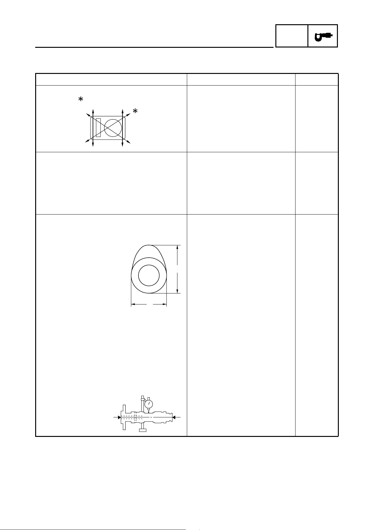
Cylinder:
Bore size 82.970 ~ 83.020 mm
(3.2665 ~ 3.2685 in)
Taper limit ---- 0.05 mm
Out of round limit ---- 0.01 mm
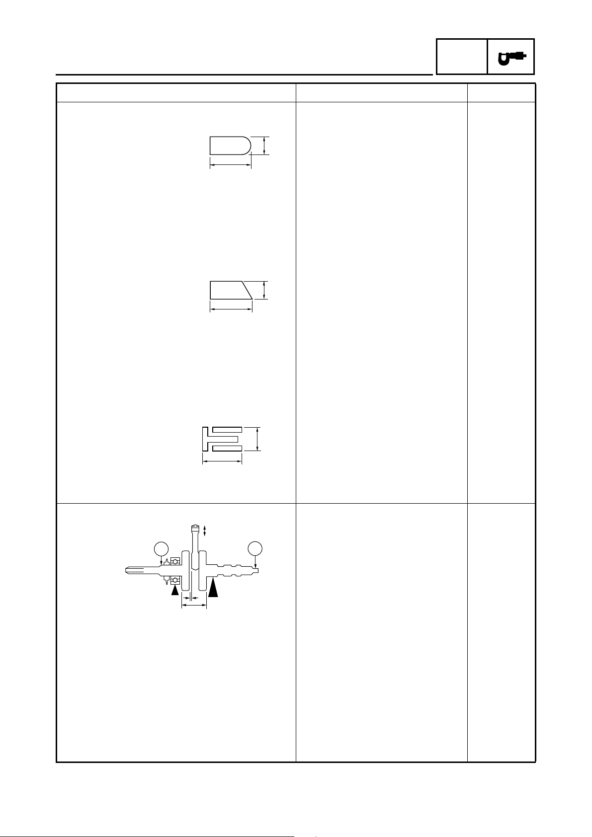
Camshaft:
Drive method Chain drive (left) ----
Cam dimensions
83.100 mm
(3.2720 in)
(0.0016 in)
(0.0004 in)
A
B
Intake “A” 40.62 ~ 40.72 mm
(1.5992 ~ 1.6031 in)
“B” 32.18 ~ 32.28 mm
(1.2669 ~ 1.2709 in)
Exhaust “A” 40.62 ~ 40.72 mm
(1.5992 ~ 1.6031 in)
“B” 32.18 ~ 32.28 mm
(1.2669 ~ 1.2709 in)
Camshaft runout limit ---- 0.03 mm
40.52 mm
(1.5953 in)
32.08 mm
(1.2630 in)
40.52 mm
(1.5953 in)
32.08 mm
(1.2630 in)
(0.0012 in)
– 5 –
MAINTENANCE SPECIFICATIONS
SPEC
Item Standard Limit
Cam chain:
Cam chain type/No. of links 92RH2005/110 ----
Cam chain adjustment method Automatic ---Rocker arm/rocker arm shaft:
Rocker arm inside diameter 11.980 ~ 11.998 mm
(0.4717 ~ 0.4724 in)
Rocker arm shaft outside diameter 11.961 ~ 11.971 mm
(0.4709 ~ 0.4713 in)
Rocker-arm-to-rocker-arm-shaft clearance 0.009 ~ 0.037 mm
(0.0004 ~ 0.0015 in)
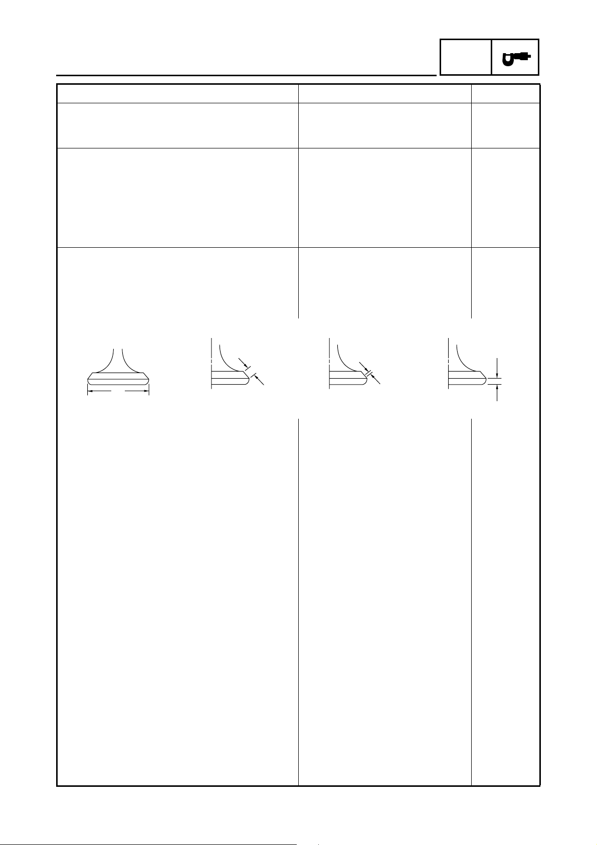
Valves, valve seats, valve guides:
Valve clearance (cold) IN 0.06 ~ 0.10 mm
(0.0024 ~ 0.0039 in)
EX 0.16 ~ 0.20 mm
(0.0063 ~ 0.0079 in)
Valve dimensions
12.058 mm
(0.4747 in)
11.931 mm
(0.4697 in)
0.080 mm
(0.0031 in)
----
----
A
Head Diameter
Face Width
B
Seat Width
C
Margin Thickness
“A” head diameter IN 39.9 ~ 40.1 mm
(1.5709 ~ 1.5787 in)
EX 33.9 ~ 34.1 mm
(1.3346 ~ 1.3425 in)
“B” face width IN 2.26 mm (0.0890 in) ----
EX 2.26 mm (0.0890 in) ----
“C” seat width IN 1.2 ~ 1.4 mm
(0.0472 ~ 0.0551 in)
EX 1.2 ~ 1.4 mm
(0.0472 ~ 0.0551 in)
“D” margin thickness IN 1.0 ~ 1.4 mm
(0.0394 ~ 0.0551 in)
EX 0.8 ~ 1.2 mm
(0.0315 ~ 0.0472 in)
Stem outside diameter IN 6.975 ~ 6.990 mm
(0.2746 ~ 0.2752 in)
EX 6.955 ~ 6.970 mm
(0.2738 ~ 0.2744 in)
Guide inside diameter IN 7.000 ~ 7.012 mm
(0.2756 ~ 0.2761 in)
EX 7.000 ~ 7.012 mm
(0.2756 ~ 0.2761 in)
Stem-to-guide clearance IN 0.010 ~ 0.037 mm
(0.0004 ~ 0.0015 in)
EX 0.030 ~ 0.057 mm
(0.0012 ~ 0.0022 in)
D
----
----
1.6 mm
(0.0630 in)
1.6 mm
(0.0630 in)
----
----
6.950 mm
(0.2736 in)
6.915 mm
(0.2722 in)
7.03 mm
(0.2768 in)
7.03 mm
(0.2768 in)
0.080 mm
(0.0031 in)
0.100 mm
(0.0039 in)
– 6 –
MAINTENANCE SPECIFICATIONS
Item Standard Limit
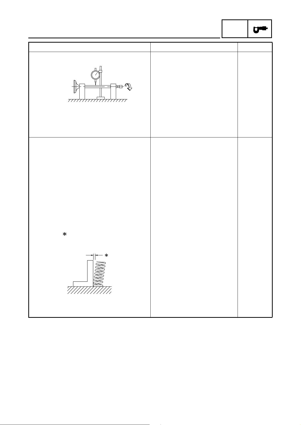
Stem runout limit ---- 0.01 mm
SPEC
(0.0004 in)
Valve seat width IN 1.2 ~ 1.4 mm
(0.0472 ~ 0.0551 in)
EX 1.2 ~ 1.4 mm
(0.0472 ~ 0.0551 in)
Valve spring:
Inner spring
Free length IN 39.9 mm (1.57 in) 37.9 mm
EX 39.9 mm (1.57 in) 37.9 mm
Set length (valve closed) IN 33.6 mm (1.32 in) ----
EX 33.6 mm (1.32 in) ----
Compressed pressure
(installed) IN 104.9 ~ 120.6 N
(10.7 ~ 12.3 kg, 23.58 ~ 27.11 lb)
EX 104.9 ~ 120.6 N
(10.7 ~ 12.3 kg, 23.58 ~ 27.11 lb)
Tilt limit IN 2.5°/1.7 mm
EX 2.5°/1.7 mm
----
----
(1.49 in)
(1.49 in)
----
----
(2.5°/0.07 in)
(2.5°/0.07 in)
Direction of winding
(top view) IN Counterclockwise ----
EX Counterclockwise ----
– 7 –
MAINTENANCE SPECIFICATIONS
Item Standard Limit
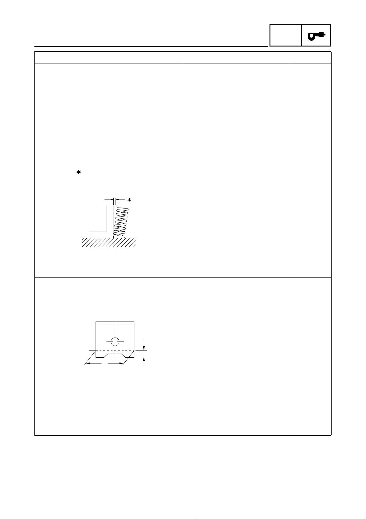
Outer spring
Free length IN 43.27 mm (1.70 in) 41.27 mm
EX 43.27 mm (1.70 in) 41.27 mm
Set length (valve closed) IN 36.6 mm (1.44 in) ----
EX 36.6 mm (1.44 in) ----
Compressed pressure
(installed) IN 235.4 ~ 251.1 N
(24.0 ~ 25.6 kg, 52.92 ~ 56.45 lb)
EX 235.4 ~ 251.1 N
(24.0 ~ 25.6 kg, 52.92 ~ 56.45 lb)
Tilt limit IN ---- 2.5°/1.9 mm
EX ---- 2.5°/1.9 mm
SPEC
(1.62 in)
(1.62 in)
----
----
(2.5°/0.07 in)
(2.5°/0.07 in)
Direction of winding
(top view) IN Clockwise ----
EX Clockwise ----
Piston:
Piston to cylinder clearance 0.040 ~ 0.060 mm
(0.0016 ~ 0.0024 in)
Piston size “D” 82.920 ~ 82.970 mm
(3.2646 ~ 3.2665 in)
H
D
Measuring point “H” 5 mm (0.20 in) ----
Piston offset 0.5 mm (0.0200 in) ----
Offset direction Intake side ----
Piston pin bore inside diameter 19.004 ~ 19.015 mm
(0.7482 ~ 0.7486 in)
Piston pin outside diameter 18.991 ~ 19.000 mm
(0.7477 ~ 0.7480 in)
0.150 mm
(0.0059 in)
----
19.045 mm
(0.7498 in)
18.971 mm
(0.7469 in)
– 8 –
MAINTENANCE SPECIFICATIONS
Item Standard Limit
Piston rings:
Top ring
B
T
Type Barrel ---Dimensions (B × T) 1.2 × 3.3 mm (0.05 × 0.13 in) ---End gap (installed) 0.20 ~ 0.40 mm
(0.008 ~ 0.016 in)
Side clearance (installed) 0.03 ~ 0.08 mm
(0.0012 ~ 0.0032 in)
2nd ring
B
T
Type Taper ---Dimensions (B × T) 1.5 × 3.4 mm (0.06 × 0.13 in) ---End gap (installed) 0.20 ~ 0.40 mm
(0.008 ~ 0.016 in)
Side clearance 0.03 ~ 0.07 mm
(0.0012 ~ 0.0028 in)
Oil ring
SPEC
0.65 mm
(0.0256 in)
0.13 mm
(0.0051 in)
0.75 mm
(0.0295 in)
0.13 mm
(0.0051 in)
B
T
Dimensions (B × T) 2.8 × 2.8 mm (0.11 × 0.11 in) ---End gap (installed) 0.3 ~ 0.9 mm (0.01 ~ 0.04 in) ----
Crankshaft:
E
C1
B
A
Crank width “A” 58.95 ~ 59.00 mm
C2
----
(2.321 ~ 2.323 in)
Runout limit C1 ---- 0.03 mm
(0.0012 in)
C2 ---- 0.03 mm
(0.0012 in)
Big end side clearance “B” 0.35 ~ 0.85 mm
(0.0138 ~ 0.0335 in)
Big end radial clearance “E” 0.004 ~ 0.023 mm
1.0 mm
(0.04 in)
----
(0.0002 ~ 0.0009 in)
– 9 –
MAINTENANCE SPECIFICATIONS
Item Standard Limit
Balancer:
Balancer drive method Gear ---Automatic centrifugal clutch:
Clutch shoe thickness 1.5 mm (0.06 in) 1.0 mm
Clutch-in revolution 1,950 ~ 2,350 r/min ----
Clutch-stall revolution 3,350 ~ 3,850 r/min ---Transmission:
Main axle deflection limit ---- 0.08 mm
Drive axle deflection limit ---- 0.08 mm
Shifter:
Shifter type Shift cam and guide bar ---Air filter oil grade: Engine oil ---Carburetor:
I. D. mark 5UH1 00 ----
Main jet (M.J) #130 ----
Main air jet (M.A.J) #70 ----
Jet needle (J.N) 5ETY1-2 ----
Needle jet (N.J) P-2M ----
Pilot air jet (P.A.J.1) #80 ----
Pilot air jet (P.A.J.2) 1.3 ----
Pilot outlet (P.O) 0.8 ----
Pilot jet (P.J) #17.5 ----
Bypass 1 (B.P.1) 0.8 ----
Bypass 2 (B.P.2) 0.8 ----
Bypass 3 (B.P.3) 0.8 ----
Pilot screw (P.S) 1-1/2 turns out ----
Valve seat size (V.S) 2.0 ----
Starter jet (G.S.1) 57.5 ----
Starter jet (G.S.2) 0.9 ----
Throttle valve size (Th.V) 100 ----
Float height (F.H) 13.0 mm (0.51 in) ----
Fuel level (F.L) 4.0 ~ 5.0 mm (0.16 ~ 0.20 in) ----
Engine idle speed 1,450 ~ 1,550 r/min ----
Intake vacuum 32 kPa (240 mmHg, 9.4 inHg) ----
SPEC
(0.04 in)
(0.0031 in)
(0.0031 in)
– 10 –
MAINTENANCE SPECIFICATIONS
SPEC
Item Standard Limit
Oil pump:
Oil filter type Foam ----
Oil pump type Trochoid ----
Tip clearance 0.15 mm (0.006 in) 0.20 mm
(0.008 in)
Side clearance 0.04 ~ 0.09 mm
----
(0.002 ~ 0.004 in)
Bypass valve setting pressure 78 ~ 118 kPa (0.78 ~ 1.18 kg/cm
2
,
----
11.3 ~ 17.1 psi)
Oil pressure (hot) 20 kPa (0.20 kg/cm
2
, 2.9 psi) at
----
1,500 r/min
Pressure check location Cylinder head ---Shaft drive:
Middle gear backlash 0.1 ~ 0.3 mm (0.004 ~ 0.012 in) ----
Final gear backlash 0.1 ~ 0.2 mm (0.004 ~ 0.008 in) ----
Differential gear backlash 0.05 ~ 0.25 mm
----
(0.0020 ~ 0.0098 in)
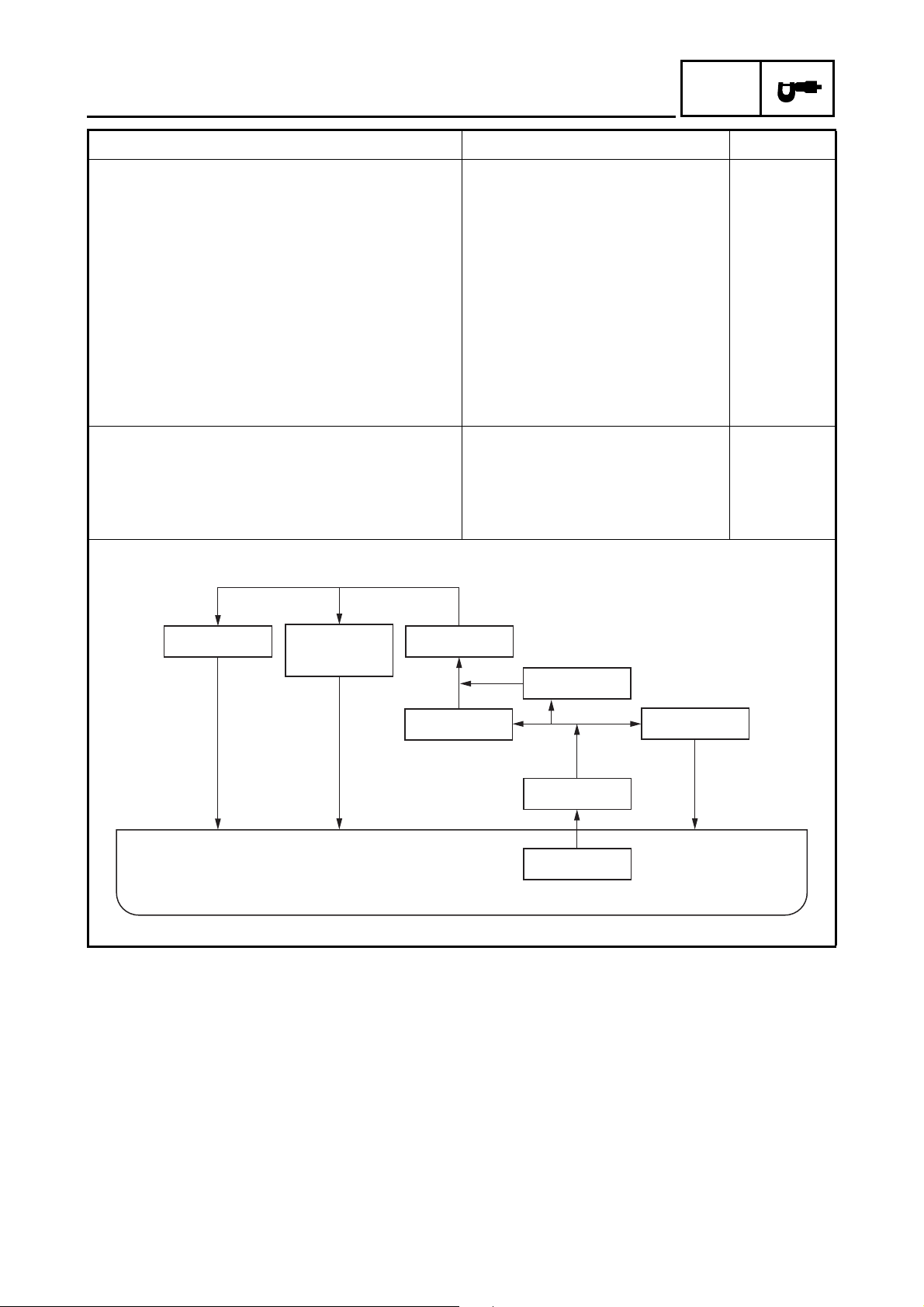
Lubrication chart:
Crank pin,
clutch
Oil pan
Oil filterCylinder head
Oil cooler
Relief valve
Transmission
Oil pump
Oil strainer
– 11 –
MAINTENANCE SPECIFICATIONS
Item Standard Limit
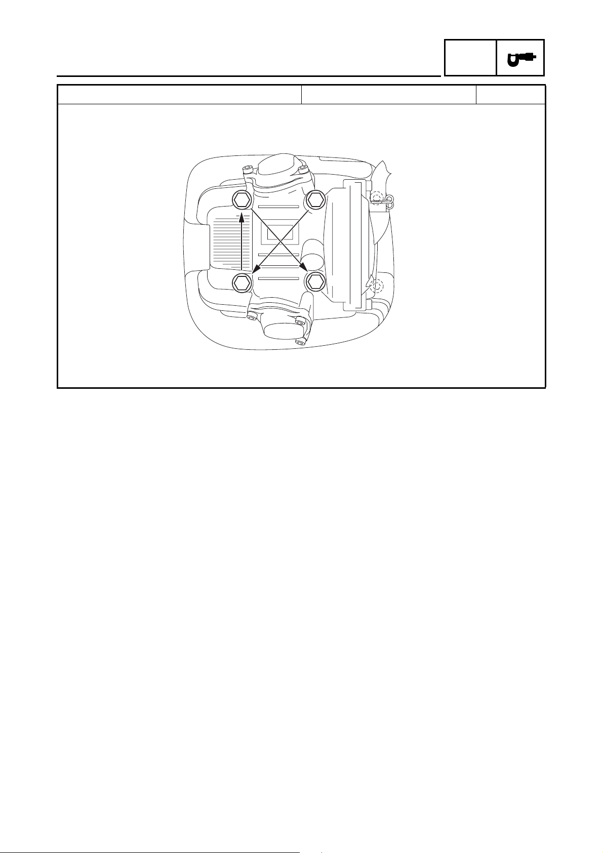
Cylinder head tightening sequence:
3
SPEC
5
1
2
4
6
– 12 –
Tightening torques
MAINTENANCE SPECIFICATIONS
SPEC
Part to be tightened
Part
name
Thread
size
Q’ty
Tightening torque
Nm m·kg ft·lb
Cylinder head (exhaust pipe) Stud bolt M6 2 7 0.7 5.1
Cylinder head Bolt M10 4 32 3.2 23
Bolt M8 2 20 2.0 14
Camshaft bearing retainer Bolt M6 2 8 0.8 5.8
Spark plug — M12 1 18 1.8 13
Oil gallery bolt Bolt M6 1 7 0.7 5.1
Cylinder Bolt M6 1 10 1.0 7.2
Starter pulley Bolt M10 1 55 5.5 40
Balancer driven gear Nut M16 1 60 6.0 43
Valve adjusting screw Nut M7 2 20 2.0 14
Tappet cover (intake) Bolt M6 2 10 1.0 7.2
Tappet cover (exhaust) Bolt M6 3 10 1.0 7.2
Camshaft sprocket Bolt M10 1 60 6.0 43
Camshaft sprocket cover Bolt M6 2 10 1.0 7.2
Timing chain tensioner cap Bolt M11 1 23 2.3 17
Timing chain tensioner Bolt M6 2 11 1.1 8.0
Timing chain guide (intake) Bolt M6 2 10 1.0 7.2
Oil strainer Bolt M5 2 4 0.4 2.9
Oil filter union bolt — M20 1 68 6.8 49
Oil filter cartridge — M20 1 17 1.7 12
Oil cooler Bolt M6 4 7 0.7 5.1
Oil cooler fan Bolt M6 3 6 0.6 4.3
Oil hose union bolt — M14 2 50 5.0 36
Oil hose (oil cooler side) — M16 2 21 2.1 15
Oil hose (crankcase side) — M16 2 35 3.5 25
Oil pump assembly Bolt M6 3 7 0.7 5.1
Oil pump housing Screw M5 1 5 0.5 3.6
Plate (oil pump driven gear) Bolt M6 2 7 0.7 5.1
Intake manifold Bolt M8 2 20 2.0 14
Crankcase Bolt M8 3 20 2.0 14
Bolt M6 15 10 1.0 7.2
Oil drain bolt Bolt M12 1 23 2.3 17
Bearing retainer (right crankcase) Bolt M6 2 10 1.0 7.2
Bearing retainer (left crankcase)
Torx
screw
M6 1 11 1.1 8.0
Crankcase oil passage plug — M14 1 25 2.5 18
Lead holder (stator assembly) Bolt M5 2 7 0.7 5.1
Drive belt case Bolt M6 9 10 1.0 7.2
Bearing housing (primary sheave) Bolt M6 4 10 1.0 7.2
Drive belt case cover Bolt M6 14 10 1.0 7.2
Crankcase cover Bolt M6 12 10 1.0 7.2
Stator assembly Screw M6 3 7 0.7 5.1
Remarks
LT
LT
– 13 –
MAINTENANCE SPECIFICATIONS
SPEC
Part to be tightened
Part
name
Thread
size
Q’ty
Tightening torque
Remarks
Nm m·kg ft·lb
Pickup coil Bolt M5 2 7 0.7 5.1
Starter one-way clutch Bolt M8 3 30 3.0 22
Recoil starter Bolt M6 4 10 1.0 7.2
Clutch carrier assembly Nut M22 1 140 14.0 100 Stake.
Clutch housing assembly Bolt M6 8 10 1.0 7.2
Middle drive shaft bearing retainer
Torx
screw
M8 4 25 2.5 18
Middle drive shaft drive pinion gear Nut M22 1 130 13.0 94 Stake.
Middle drive shaft bearing housing Bolt M8 4 32 3.2 23
Middle driven pinion gear bearing
retainer
Universal joint yoke
(middle driven pinion gear)
Middle driven pinion gear bearing
housing
Middle driven shaft bearing retainer Nut M55 1 80 8.0 58
Nut M65 1 110 11.0 80
Nut M14 1 97 9.7 70
Bolt M8 4 25 2.5 18
Left-handed
threads
Left-handed
threads
Primary sliding sheave cap Screw M4 3 3 0.3 2.2
Primary sliding sheave assembly Nut M16 1 100 10.0 72
Secondary sheave assembly Nut M16 1 100 10.0 72
Secondary sheave spring retainer Nut M36 1 90 9.0 65
Shift shaft stopper bolt — M14 1 18 1.8 13
Shift lever assembly Bolt M6 1 14 1.4 10
Neutral switch — M10 1 17 1.7 12
Reverse switch — M10 1 17 1.7 12
Thermo unit — M12 1 20 2.0 14
Muffler and exhaust pipe Bolt M8 2 15 1.5 11
Exhaust pipe Nut M6 2 12 1.2 8.7
Muffler Bolt M10 2 25 2.5 18
Exhaust pipe bracket (exhaust pipe) Bolt M6 2 14 1.4 10
Exhaust pipe bracket (engine) Bolt M6 2 10 1.0 7.2
Starter motor Bolt M6 2 10 1.0 7.2
Speedometer gear unit Bolt M6 2 10 1.0 7.2
Screw M6 2 7 0.7 5.1
LT
LT
LT
LT
LT
LT
– 14 –

MAINTENANCE SPECIFICATIONS
CHASSIS
Item Standard Limit
Steering system:
Steering bearing type Ball and race bearing ----
Front suspension:
Shock absorber travel 99 mm (3.90 in) ---Spring free length 265 mm (10.43 in) ---Spring fitting length 231.9 mm (9.13 in) ---Spring rate (K1) 13.5 N/mm
(1.35 kg/mm, 75.60 lb/in)
Stroke (K1) 0 ~ 99 mm (0 ~ 3.90 in) ---Optional spring No ----
Rear suspension:
Shock absorber travel 126 mm (4.96 in) ---Spring free length 317 mm (12.48 in) ---Spring fitting length 283.1 mm (11.15 in) ---Spring rate (K1) 27.4 N/mm
(2.74 kg/mm, 153.43 lb/in)
Stroke (K1) 0 ~ 126 mm (0 ~ 4.96 in) ---Optional spring No ----
Swingarm:
Free play limit end ---- 1 mm
side ---- 1 mm
Front wheel:
Type Panel wheel ---Rim size 12 × 6.0 AT ---Rim material Steel ---Rim runout limit radial ---- 2 mm
lateral ---- 2 mm
Rear wheel:
Type Panel wheel ---Rim size 12 × 7.5 AT ---Rim material Steel ---Rim runout limit radial ---- 2 mm
lateral ---- 2 mm
SPEC
----
----
(0.04 in)
(0.04 in)
(0.08 in)
(0.08 in)
(0.08 in)
(0.08 in)
– 15 –

MAINTENANCE SPECIFICATIONS
Item Standard Limit
Front disc brake:
Type Dual ---Disc outside diameter × thickness 200.0 × 3.5 mm (7.87 × 0.14 in) ---Pad thickness inner 4.5 mm (0.18 in) 1 mm
Pad thickness outer 4.5 mm (0.18 in) 1 mm
Master cylinder inside diameter 14 mm (0.55 in) ---Caliper cylinder inside diameter 32 mm (1.26 in) ---Brake fluid type DOT 4 ----
Rear drum brake:
Type Leading, trailing ---Brake drum inside diameter 160 mm (6.30 in) 161 mm
Lining thickness 4.0 mm (0.16 in) 2 mm
Brake lever and brake pedal:
Brake lever free play (pivot) front 0 mm (0 in) ----
rear 3 ~ 5 mm (0.12 ~ 0.20 in) ---Brake pedal free play 20 ~ 30 mm (0.79 ~ 1.18 in) ---Throttle lever free play 3 ~ 5 mm (0.12 ~ 0.20 in) ----
SPEC
(0.04 in)
(0.04 in)
(6.34 in)
(0.08 in)
– 16 –
Tightening torques
MAINTENANCE SPECIFICATIONS
SPEC
Part to be tightened Thread size
Tightening torque
Nm m·kg ft·lb
Engine bracket (front-upper) and frame M8 33 3.3 24
Engine bracket (front-lower) and frame M8 33 3.3 24
Engine bracket (front-upper) and engine M10 42 4.2 30
Engine bracket (front-lower) and engine M10 42 4.2 30
Engine and frame (rear-upper) M10 56 5.6 40
Engine and frame (rear-lower) M10 56 5.6 40
Frame and bearing retainer (steering stem holder
bearing)
M42 40 4.0 29
Select lever assembly and frame M8 23 2.3 17
Swingarm M12 82 8.2 59
Rear shock absorber and frame M12 82 8.2 59
Final gear case and swingarm M10 63 6.3 45
Final gear case and rear axle housing M10 63 6.3 45
Swingarm and rear axle housing M12 63 6.3 45
Differential gear case and frame M10 55 5.5 40
Front arm and frame M10 45 4.5 32
Front shock absorber and frame M10 45 4.5 32
Front shock absorber and upper front arm M10 45 4.5 32
Steering stem, pitman arm and frame M14 190 19.0 140
Steering stem holder and frame M8 23 2.3 17
Steering stem and handlebar holder M8 23 2.3 17
Pitman arm and tie-rod end M12 30 3.0 22
Tie-rod and locknut M12 40 4.0 29
Steering knuckle and upper front arm M12 30 3.0 22
Steering knuckle and lower front arm M12 30 3.0 22
Steering knuckle and tie-rod M12 30 3.0 22
Fuel tank and fuel cock M6 4 0.4 2.9
Fuel tank M6 10 1.0 7.2
Front wheel and wheel hub M10 55 5.5 40
Front axle and wheel hub M16 150 15.0 110
Steering knuckle and brake caliper M8 30 3.0 22
Front brake disc and wheel hub M8 30 3.0 22
Rear wheel and rear wheel hub M10 55 5.5 40
Rear axle and nut M16 150 15.0 110
Brake drum cover and brake shoe plate M6 7 0.7 5.1
Front brake hose and steering knuckle M6 7 0.7 5.1
Front brake hose and upper front arm M6 7 0.7 5.1
Front brake hose and frame M6 7 0.7 5.1
Front brake pipe nut M10 19 1.9 13
Front brake hose union bolt M10 27 2.7 19
Bleed screw M8 6 0.6 4.3
Remarks
LT
LS
Use lock
washer
LT
– 17 –

MAINTENANCE SPECIFICATIONS
SPEC
Part to be tightened Thread size
Tightening torque
Nm m·kg ft·lb
Master cylinder and handlebar M6 7 0.7 5.1
Footrest bracket and frame M8 16 1.6 11
Front bumper and frame M8 34 3.4 24
Front carrier and frame M8 34 3.4 24
Front carrier and front bumper M8 34 3.4 24
Rear carrier and frame M8 34 3.4 24
Engine skid plate M6 7 0.7 5.1
Differential gear oil filler bolt M14 23 2.3 17
Differential gear oil drain bolt M10 10 1.0 7.2
Differential gear case and bearing housing M8 25 2.5 18
Gear motor M8 13 1.3 9.4
Final gear oil filler bolt M14 23 2.3 17
Final gear oil drain bolt M14 23 2.3 17
Bearing retainer (drive pinion gear) M65 100 10.0 72
Final gear case and bearing housing M10 40 4.0 29
M8 23 2.3 17
Battery holding bracket M6 7 0.7 5.1
Footrest board and footrest bracket M6 7 0.7 5.1
Trailer hitch bracket M10 32 3.2 23
Front brake pad holding bolt M8 17 1.7 12
Front brake caliper retaining bolt M8 17 1.7 12
Rear brake light switch bracket M8 23 2.3 17
Rear brake light switch cover M6 7 0.7 5.1
Rear brake lever holder bracket M6 7 0.7 5.1
Brake camshaft lever M6 9 0.9 6.5
Oil hose protector M6 7 0.7 5.1
Remarks
– 18 –

MAINTENANCE SPECIFICATIONS
ELECTRICAL
Item Standard Limit
Voltage: 12 V ---Ignition system:
Ignition timing (B.T.D.C.) 10°/ 1,500 r/min ---Advancer type Digital ----
C.D.I.:
Magneto model/manufacturer F4T475/MITSUBISHI ---Pickup coil resistance/color 459 ~ 561 Ω at 20 °C (68 °F)/
White/Red – White/Green
Rotor rotation direction sensing coil
resistance/color
C.D.I. unit model/manufacturer F8T40371/MITSUBISHI ----
Ignition coil:
Model/manufacturer 2JN/YAMAHA ---Minimum spark gap 6 mm (0.24 in) ---Primary winding resistance 0.18 ~ 0.28 Ω at 20 °C (68 °F) ---Secondary winding resistance 6.32 ~ 9.48 kΩ at 20 °C (68 °F) ----
Spark plug cap:
Type Resin ---Resistance 10 kΩ ----
Charging system:
Type A.C. magneto generator ---Model/manufacturer F4T475/MITSUBISHI ---Nominal output 14 V 18 A at 5,000 r/min ---Charging coil resistance/color 0.49 ~ 0.62 Ω at 20 °C (68 °F)/
Rectifier/regulator:
Regulator type Semi conductor-short circuit ---No-load regulated voltage (DC) 14.1 ~ 14.9 V ---Model/manufacturer SH640E-11/SHINDENGEN ---Capacity 14 A ---Withstand voltage 200 V ----
Battery:
Specific gravity 1.32 ----
Electric starter system:
Type Constant mesh ---Starter motor
Model/manufacturer SM-13/MITSUBA ---Output 0.7 kW ---Armature coil resistance 0.0015 ~ 0.0025 Ω at
0.086 ~ 0.105 Ω at 20 °C (68 °F)/
Red – White/Blue
White – White
20 °C (68 °F)
SPEC
----
----
----
----
– 19 –

MAINTENANCE SPECIFICATIONS
Item Standard Limit
Brush overall length 12.0 mm (0.47 in) 4 mm
Spring force 7.65 ~ 10.01 N (780 ~ 1,021 g,
27.53 ~ 36.04 oz)
Commutator diameter 28 mm (1.10 in) 27 mm
Mica undercut 0.7 mm (0.03 in) ----
Starter relay
Model/manufacturer MS5F-561/JIDECO ---Amperage rating 180 A ---Coil winding resistance 4.18 ~ 4.62 Ω at 20 °C (68 °F) ----
Electric fan:
Running rpm 6,350 r/min ----
Thermostat switch:
Thermo unit
Model/manufacturer 4GB/DENSO ----
Circuit breakers:
Type Fuse ---Amperage for individual circuit
Main fuse 30 A × 1 ---Headlight fuse 15 A × 1 ---Ignition fuse 15 A × 1 ---Auxiliary DC jack fuse 10 A × 1 ---Four-wheel drive fuse 3 A × 1 ---Signaling system fuse 10 A × 1 ---Reserve 30 A × 1 ---Reserve 15 A × 1 ---Reserve 10 A × 1 ---Reserve 3 A × 1 ----
SPEC
(0.16 in)
----
(1.06 in)
– 20 –
 Loading...