

Page 1
READ THIS MANUAL CAREFULLY!
It contains important safety information.
LIRE ATTENTIVEMENT CE MANUEL!
Il comprend d’importantes informations de sécurité.
¡LEA ESTE MANUAL ATENTAMENTE!
Contiene indicaciones importantes acerca de la seguridad.
OWNER’S MANUAL
MANUEL DU PROPRIÉTAIRE
MANUAL DEL PROPIETARIO
YFM25RA/YFM25RSEA
YFM250RA/YFM250RSEA
1BT-28199-61
Page 2

PRINTED ON RECYCLED PAPER
IMPRIMÉ SUR PAPIER RECYCLÉ
IMPRESO EN PAPEL RECICLADO
YAMAHA MOTOR CO., LTD.
PRINTED IN JAPAN
2010.04-0.8×1 CR
(E,F,S)
Page 3
READ THIS MANUAL CAREFULLY!
It contains important safety information.
OWNER’S MANUAL
YFM25RA/YFM25RSEA
YFM250RA/YFM250RSEA
1BT-28199-61-E0
Page 4

EBU29102
Read this manual carefully before operating this vehicle. This manual should stay with this ve-
hicle if it is sold.
EC Declaration of Conformity
conforming to Directive 2006/42/EC
We, YAMAHA MOTOR CO., LTD. 2500 Shingai, Iwata, Japan,
declare in sole responsibility, that the product
YFM250R (YFM25R) (JY4AG03W0A0006915–)
(Make, model)
to which this declaration applies, conforms to the essential health
and safety requirements of Directive 2006/42/EC
(If applicable)
and to the other relevant Directives of EEC
(Title and/or number and date of issue of the other Directives of EEC)
(If applicable)
To effect correct application of the essential health and safety requirements
stated in the Directives of EEC, the following-standards and/or technical
specifications were consulted:
(Title and/or number and date of issue of standards and/or specifications)
Authorized Representative
YAMAHA MOTOR EUROPE N.V.
Koolhovenlaan 101, 1119 NC Schiphol-Rijk, The Netherlands
2004/108/EC
ANSI/SVIA 1-2007
Signature
General Manager
RV Engineering Division
MC Operations
Date of Issue
Shinya Shimada
6 January, 2010
Page 5

EBU17170
INTRODUCTION
EBU17322
Congratulations on your purchase of the Yamaha YFM25RA/YFM25RSEA/YFM250RA/YFM250RSEA.
This ATV represents the result of many years of Yamaha experience in the production of fine sporting, touring, and pacesetting racing machines. With the purchase of this Yamaha, you can now appreciate the high
degree of craftsmanship and reliability that have made Yamaha a leader in these fields.
This manual will provide you with a good basic understanding of the features and operation of this ATV.
This manual includes important safety information. It provides information about special techniques and skills necessary to ride the ATV. It also includes basic maintenance and inspection proce-
dures. If you have any questions regarding the operation or maintenance of your ATV, please consult a
Yamaha dealer.
AN IMPORTANT SAFETY MESSAGE:
● Read this manual completely before operating your ATV. Make sure you understand all instructions.
● Pay close attention to the warning and notice labels on the ATV.
● This ATV should not be ridden by anyone under 16 years of age.
● This ATV is a high-performance ATV for off-road use only, for sport-type recreational and competitive use
by experienced operators.
Page 6
EBU17330
IMPORTANT MANUAL INFORMATION
EBU17342
FAILURE TO FOLLOW THE WARNINGS CONTAINED IN THIS MANUAL CAN RESULT IN SERIOUS INJURY OR DEATH.
Particularly important information is distinguished in this manual by the following notations:
This is the safety alert symbol. It is used to alert you to potential personal injury hazards. Obey all safety messages that follow this symbol to avoid possible injury or death.
WARNING
NOTICE
TIP
A WARNING indicates a hazardous situation which, if not avoided,
could result in death or serious injury.
A NOTICE indicates special precautions that must be taken to avoid
damage to the vehicle or other property.
A TIP provides key information to make procedures easier or clearer.
* Product and specifications are subject to change without notice.
Page 7

EBU17350
IMPORTANT NOTICE
EBU17372
This ATV is designed and manufactured for use on unpaved surfaces only. It is unsafe to operate this ATV
on any paved surface, paved street, paved road or motorway.
Please check your local riding laws and regulations before operating this ATV.
EBU17390
YFM25RA/YFM25RSEA
YFM250RA/YFM250RSEA
OWNER ’S MANUAL
©2010 by Yamaha Motor Co., Ltd.
1st edition, March 2010
All rights reserved.
Any reprinting or unauthorized use
without the written permission of
Yamaha Motor Co., Ltd.
is expressly prohibited.
Printed in Japan.
Page 8

EBU17420
TABLE OF CONTENTS
LOCATION OF THE WARNING AND
SPECIFICATION LABELS ............................ 1-1
SAFETY INFORMATION .............................. 2-1
DESCRIPTION .............................................. 3-1
Left view ...................................................... 3-1
Right view.................................................... 3-1
Controls and instruments ............................ 3-2
INSTRUMENT AND CONTROL
FUNCTIONS .................................................. 4-1
Main switch ................................................ 4-1
Indicator light .............................................. 4-2
Handlebar switches .................................... 4-2
Throttle lever .............................................. 4-3
Speed limiter .............................................. 4-4
Clutch lever ................................................ 4-4
Brake lever (YFM25RA/YFM250RA) .......... 4-5
Brake lever
(YFM25RSEA/YFM250RSEA) ................. 4-5
Brake pedal ................................................ 4-6
Parking brake lever .................................... 4-6
Shift pedal .................................................. 4-7
Fuel tank cap ..............................................4-8
Fuel .............................................................4-8
Fuel cock ..................................................4-10
Starter (choke) ..........................................4-11
Seat ..........................................................4-12
Adjusting the front shock absorber
assemblies (YFM25RA/YFM250RA) .......4-13
Adjusting the front shock absorber
assemblies
(YFM25RSEA/YFM250RSEA).................4-14
Adjusting the rear shock absorber
assembly (YFM25RA/YFM250RA) ..........4-18
Adjusting the rear shock absorber
assembly
(YFM25RSEA/YFM250RSEA).................4-20
PRE-OPERATION CHECKS ..........................5-1
Fuel .............................................................5-3
Engine oil ....................................................5-3
Front and rear brakes .................................5-3
Throttle lever ...............................................5-3
Drive chain ..................................................5-4
Tires ............................................................5-4
Chassis fasteners .......................................5-6
Page 9

Instruments, lights and switches ................ 5-6
OPERATION .................................................. 6-1
Starting a cold engine ................................ 6-1
Starting a warm engine .............................. 6-2
Shifting ....................................................... 6-3
Engine break-in .......................................... 6-4
Parking ....................................................... 6-5
Parking on a slope ..................................... 6-6
Accessories and loading ............................ 6-6
RIDING YOUR ATV ...................................... 7-1
GETTING TO KNOW YOUR ATV............... 7-2
RIDE WITH CARE AND GOOD
JUDGMENT .............................................. 7-2
BE CAREFUL WHERE YOU RIDE............. 7-9
TURNING YOUR ATV .............................. 7-12
CLIMBING UPHILL ................................... 7-13
RIDING DOWNHILL.................................. 7-16
CROSSING A SLOPE............................... 7-18
CROSSING THROUGH SHALLOW
WATER ................................................... 7-19
RIDING OVER ROUGH TERRAIN ........... 7-20
SLIDING AND SKIDDING ......................... 7-21
WHAT TO DO IF... .................................... 7-22
WHAT TO DO... ........................................ 7-22
PERIODIC MAINTENANCE AND
ADJUSTMENT................................................8-1
Owner’s manual and tool kit .......................8-2
Periodic maintenance chart for the
emission control system ...........................8-3
General maintenance and lubrication
chart ..........................................................8-5
Checking the spark plug .............................8-9
Engine oil and oil filter element .................8-11
Cleaning the air filter element ...................8-14
Cleaning the spark arrester ......................8-18
Adjusting the carburetor ............................8-20
Adjusting the engine idling speed .............8-20
Adjusting the throttle cable free play .........8-21
Valve clearance ........................................8-22
Brakes .......................................................8-22
Checking the front and rear brake pads ...8-22
Checking the brake fluid level ...................8-23
Changing the brake fluid ...........................8-25
Checking the front brake lever free play ...8-25
Checking the brake pedal position ............8-25
Adjusting the parking brake free play .......8-26
Brake light switches ..................................8-27
Adjusting the clutch lever free play ...........8-28
Drive chain slack .......................................8-29
Lubricating the drive chain ........................8-31
Checking and lubricating the cables .........8-31
Page 10

Checking and lubricating the brake and
clutch levers ........................................... 8-32
Checking the shift pedal ........................... 8-33
Checking and lubricating the brake
pedal ...................................................... 8-33
Checking the wheel hub bearings ............ 8-33
Lubricating the swingarm pivots ............... 8-34
Lubricating the upper and lower arm
pivots ...................................................... 8-34
Lubricating the steering shaft ................... 8-35
Battery ...................................................... 8-35
Replacing the fuse ................................... 8-38
Replacing a headlight bulb ....................... 8-39
Adjusting a headlight beam ...................... 8-41
Replacing the tail/brake light bulb
(YFM25RA/YFM250RA).......................... 8-41
Tail/brake light
(YFM25RSEA/YFM250RSEA) ................ 8-42
Removing a wheel .................................... 8-42
Installing a wheel ...................................... 8-42
Troubleshooting ....................................... 8-43
Troubleshooting chart .............................. 8-44
CLEANING AND STORAGE.......................... 9-1
Cleaning ..................................................... 9-1
Storage ....................................................... 9-2
SPECIFICATIONS .......................................10-1
CONSUMER INFORMATION.......................11-1
Identification numbers ...............................11-1
Page 11
EBU29680
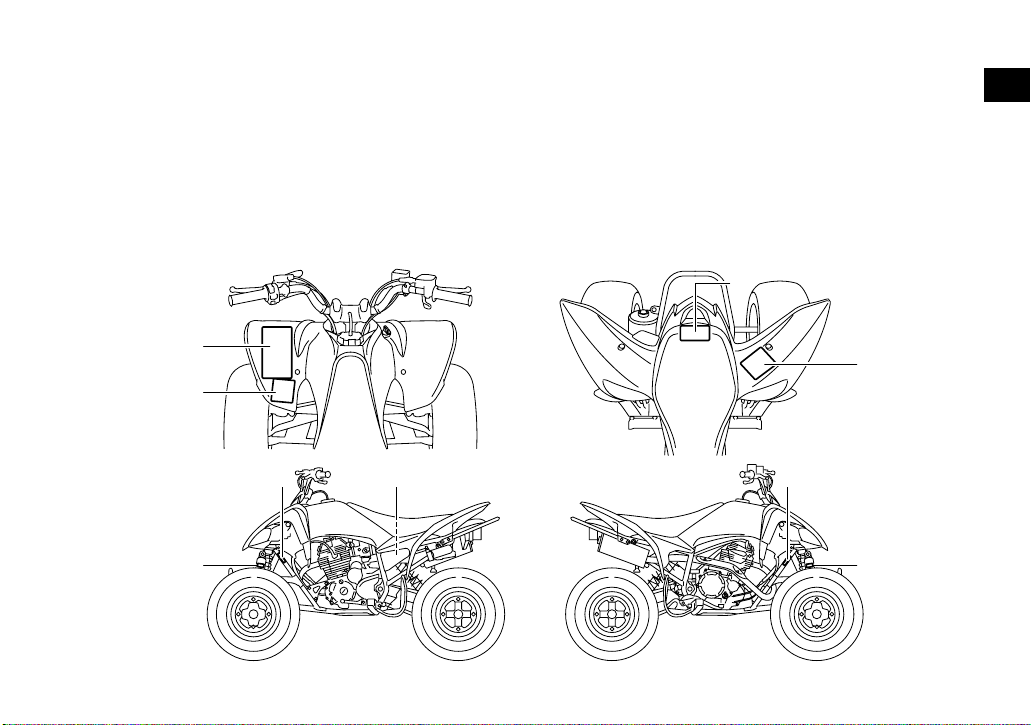
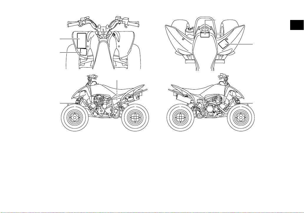
LOCATION OF THE WARNING AND SPECIFICATION LABELS
EBU29991
Read and understand all of the labels on your ATV. These labels contain important information for safe and
proper operation.
Never remove any labels from your ATV. If a label becomes difficult to read or comes off, request a replacement label from your Yamaha dealer.
For Europe
3
1
1
4
2
78 5
6
1-1
6
Page 12
12
1
4D3-2816L-20
3
43P-2816P-00
43P-2816R-01
1-2
Page 13
45
YFM250R
14.0 kW 150 kg
4D3-2156A-10
1
27.5 kPa
0.275 kgf/cm²
4.0 psi
27.5 kPa
0.275 kgf/cm²
4.0 psi
4D3-2816M-M0
6 YFM25RSEA 7 8
4AA-22259-40 4AA-22259-40
1-3
2010
YAMAHA MOTOR CO., LTD.
2500 SHINGAI, IWATA, JAPAN
8AC-2817L-00
Page 14
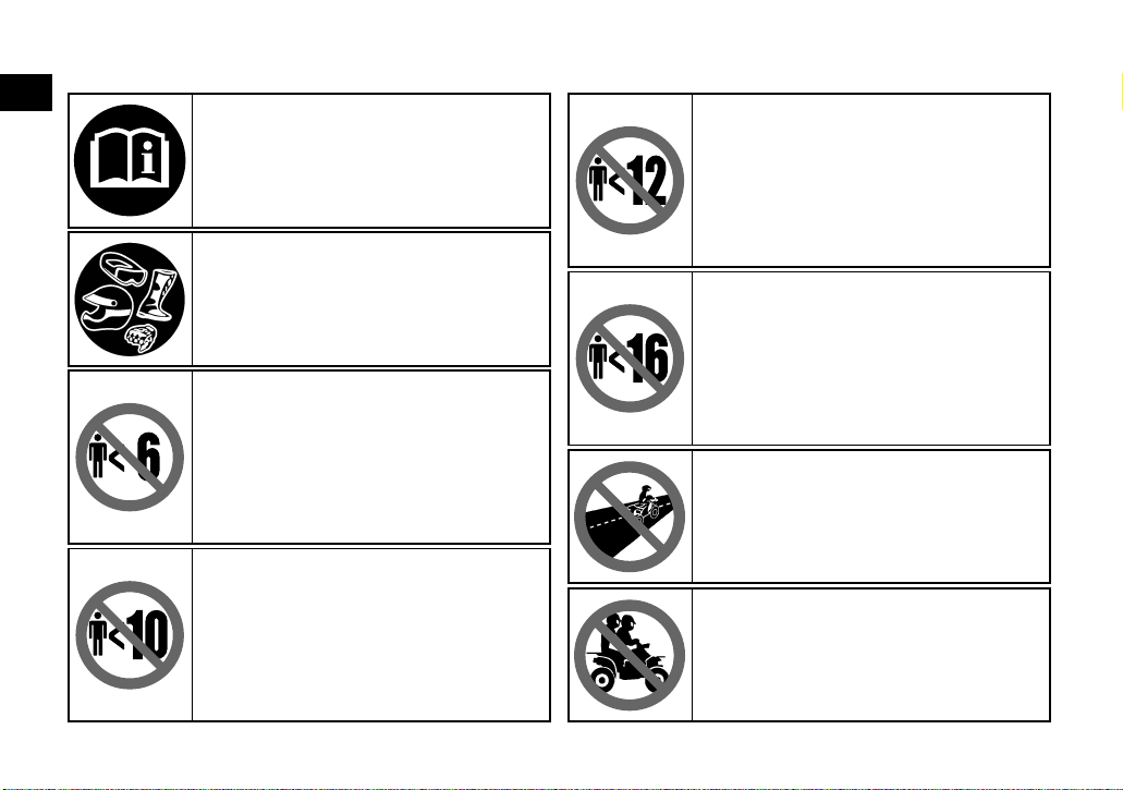
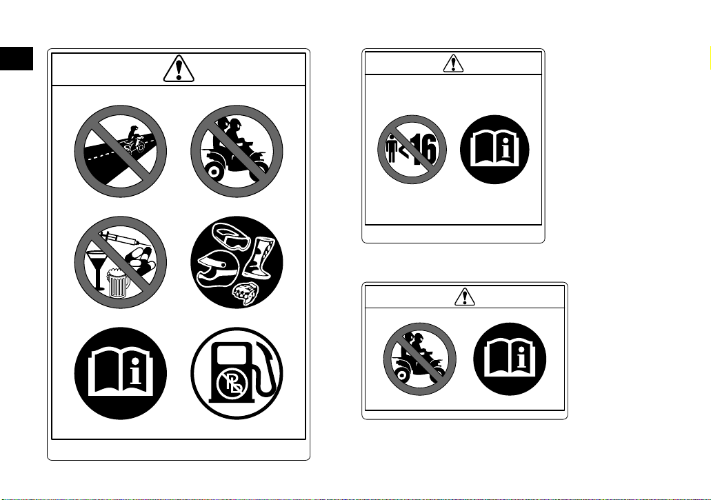
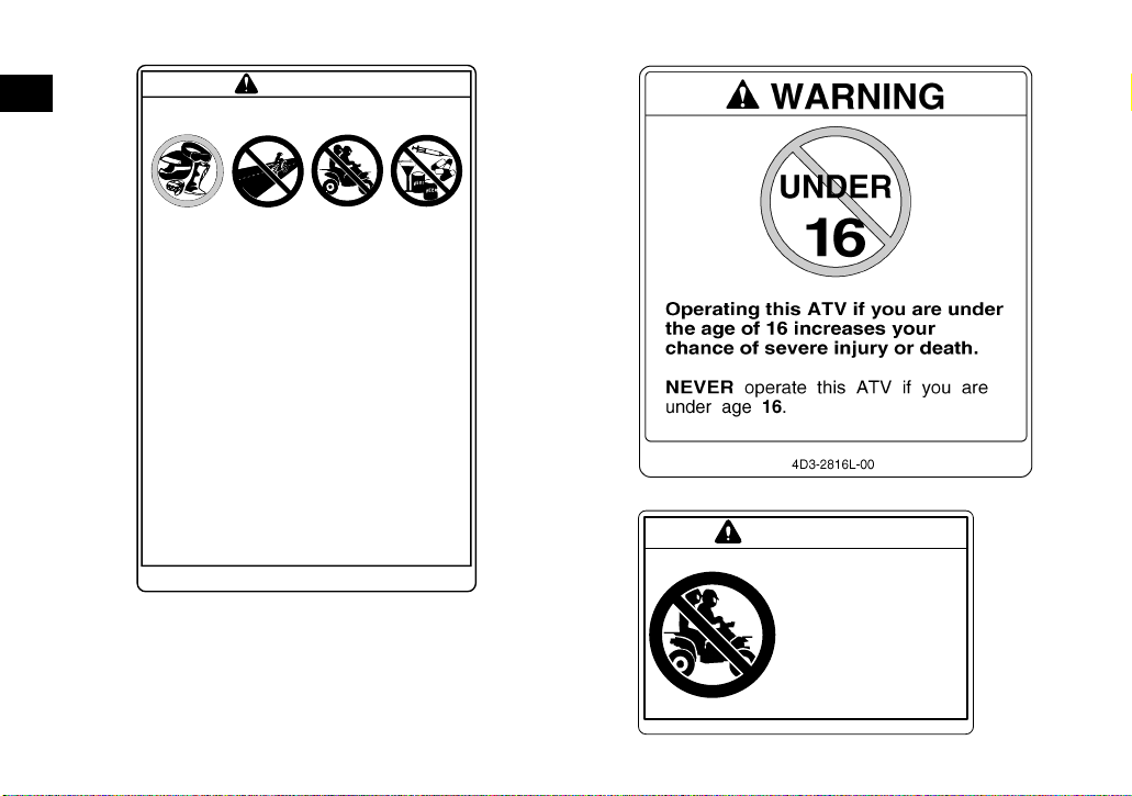
Familiarize yourself with the following pictograms and read the explanatory text, then make sure to check
the pictograms that apply to your model.
1
Read the Owner’s manual.
ALWAYS use an approved helmet and
protective gear.
NEVER permit children under age 6 to
operate this ATV.
Operation of this ATV by children under the
age of 6 increases the risk of severe injury
or death.
Adult supervision required for children under
age 16.
NEVER permit children under age 10 to
operate this ATV.
Operation of this ATV by children under the
age of 10 increases the risk of severe injury
or death.
Adult supervision required for children under
age 16.
NEVER permit children under age 12 to
operate this ATV.
Operation of this ATV by children under the
age of 12 increases the risk of severe injury
or death.
Adult supervision required for children under
age 16.
NEVER operate this ATV if you are under
age 16.
Operating this ATV if you are under the age
of 16 increases your chance of severe injury
or death.
NEVER use on paved roads.
NEVER carry passengers.
1-4
Page 15
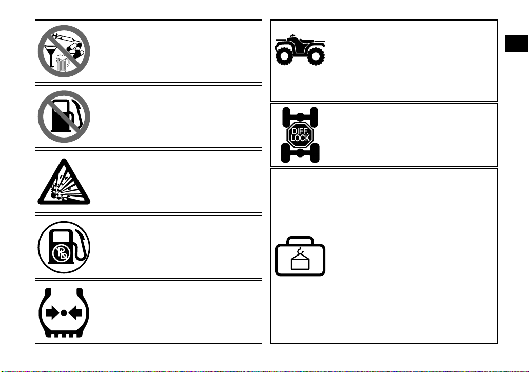
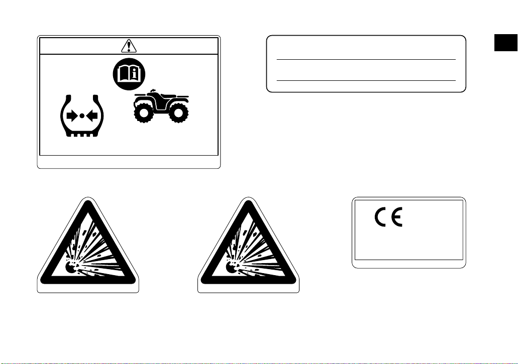
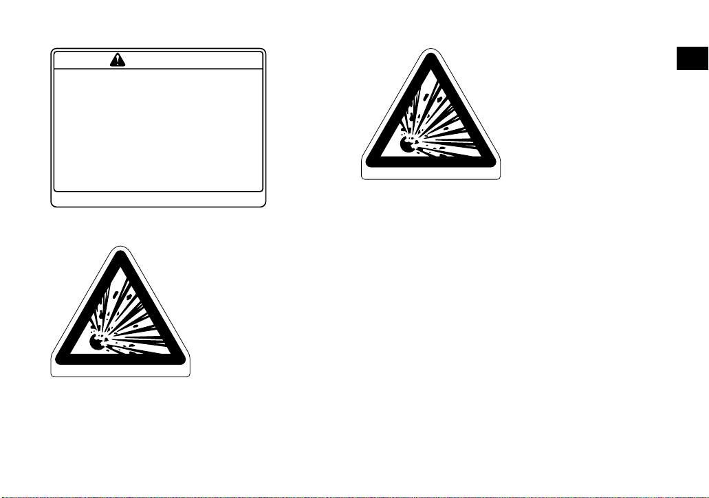
NEVER use with drugs or alcohol.
NEVER store fuel or flammable liquids.
This unit contains high-pressure nitrogen
gas.
Mishandling can cause an explosion. Do not
incinerate, puncture or open.
Use unleaded gasoline only.
Measure the tire pressure when the tires are
cold.
**.* kPa
*.** kgf/cm²
*.* psi
Adjust the tire pressure.
Improper tire pressure can cause loss of
control.
Loss of control can result in severe injury or
death.
**.* kPa
*.** kgf/cm²
*.* psi
Turning the ATV in 4WD-LOCK
(“DIFF.LOCK”) takes more effort.
Operate at a slow speed and allow extra
time and distance for maneuvers to avoid
loss of control.
This pictogram shows the loading limits
and/or maximum load capacity for this ATV.
Follow all load limits and other loading
guidelines in this manual.
Load may include the driver, passenger,
human protective gear, accessories, goods,
luggage, and all other load related items.
Make sure you do not exceed the load limits.
Overloading can cause loss of control.
Loss of control can result in severe injury or
death.
1
1-5
Page 16
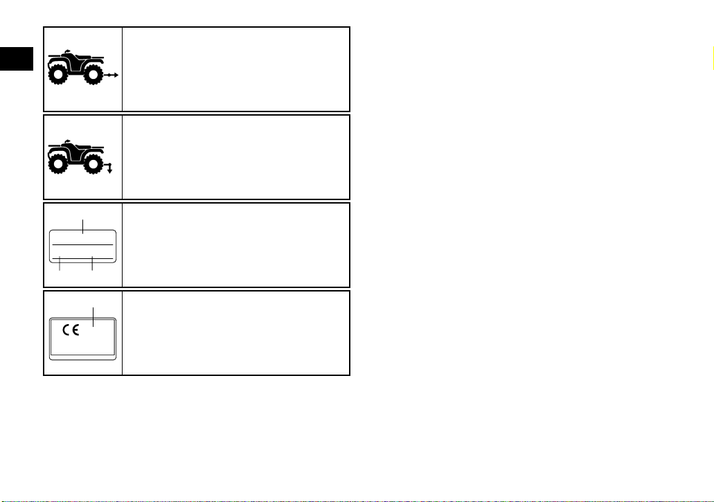
This pictogram shows trailer Hitch Tow
1
weight limit. (Combined weight of the trailer
and all cargo in the trailer.)
Overloading can cause loss of control.
Loss of control can result in severe injury or
death.
This pictogram shows trailer Hitch Tongue
weight limit. (Weight on the trailer tongue.)
Overloading can cause loss of control.
Loss of control can result in severe injury or
death.
1
******
*** kW *** kg
23
1
****
YAMAHA MOTOR CO., LTD.
2500 SHINGAI, IWATA, JAPAN
1
Model Name
2
Max. Power
3
Mass In Running Order
1
Year of construction
1-6
Page 17
For Oceania
3
1
1
4
2
6
5
1-7
5
Page 18
12
1
Improper ATV use can result in SEVERE
INJURY or DEATH.
WARNING
ALWAYS USE
AN A PPR OVED ON P UBL IC PASSENGERS WITH DRU GS
HELMET AND ROADS
PROTECTIVE
NEVER
•
without proper training or instruction.
•
at speeds too fast for your skills or
the conditions.
•
on public roads-a collision can occur
with another vehicle.
•
with a passenger-passengers affect balance
and steering and increase risk
of losing control.
ALWAYS :
• use proper riding techniques to avoid
vehicle overturns on hills and rough terrain
and it turns.
•
avoid paved surfaces-pavement may
seriously affect handling and control.
FOLLOW ALL INSTRUCTIONS AND WARNINGS.
NEVER USE
GEAR
operate :
LOCATE AND READ OWNER'S MANUAL.
NEVER CARRY NEVER USE
OR ALCOHOL
5FE-21568-11
3
WARNING
NEVER ride as a
passenger.
Passengers can cause
a loss of control,
resulting in SEVERE
INJURY or DEATH.
3B4-2151H-00
1-8
Page 19
4 5 YFM250RSEA
WARNING
Improper tire pressure or overloading can cause
loss of control.
Loss of control can result in severe injury or
death.
OPERATING TIRE PRESSURE: Set with tires cold
•
Recommended
•
Minimum
•
Never set tire pressure below minimum.
It could cause the tire to dislodge from the rim.
LOADING
•
Maximum weight capacity
Includes weight of operator, cargo and accessories.
:
:
Front
Rear
Front
Rear
4D3-2816M-00
6
4AA-22259-40
:
27.5
:
27.5
:
24.5
:
24.5
:
(
kPa,
4.0 psi
(
kPa,
4.0 psi
()
3.6 psi
kPa,
()
3.6 psi
kPa,
(220 lbs).
100 kg,
)
)
4AA-22259-40
1
1-9
Page 20
EBU17431
SAFETY INFORMATION
EBU17593
2
AN ATV IS NOT A TOY AND CAN BE HAZARDOUS TO OPERATE.
An ATV handles differently from other vehicles, including motorcycles and cars. A collision or rollover can occur quickly, even during routine
maneuvers such as turning and riding on hills or
over obstacles, if you fail to take proper precautions.
SEVERE INJURY OR DEATH can result if you do
not follow these instructions:
● Read this manual and all labels carefully and fol-
low the operating procedures described.
● Never operate an ATV without proper training or
instruction.
● Always follow the age recommendation:
– A child under 16 years old should never operate an ATV with engine size greater than 90 cc.
● Never allow a child under age 16 to operate an
ATV without adult supervision, and never allow
continued use of an ATV by a child if he or she
does not have the abilities to operate it safely.
● Never carry a passenger on an ATV.
● Always avoid operating an ATV on any paved
surfaces, including sidewalks, driveways, parking lots and paved streets.
● Never operate an ATV on any paved street,
paved road or motorway.
● Watch carefully for other vehicles when operat-
ing on unpaved public streets or roads. Make
sure you know your country’s laws and regulations before you ride on unpaved public streets
or roads.
● Never operate an ATV without wearing an ap-
proved motorcycle helmet that fits properly. You
should also wear eye protection (goggles or face
shield), gloves, boots, a long-sleeved shirt or a
jacket, and long pants.
● Never consume alcohol or drugs before or while
operating this ATV.
● Never operate at speeds too fast for your skills
or the riding conditions. Always go at a speed
that is proper for the terrain, visibility, operating
conditions, and your experience.
● Never attempt wheelies, jumps, or other stunts.
2-1
Page 21

● Always inspect your ATV each time you use it to
make sure it is in safe operating condition. Always follow the inspection and maintenance
procedures and schedules described in this
manual.
● Always keep both hands on the handlebars and
both feet on the footrests of the ATV during operation.
● Always go slowly and be extra careful when op-
erating on unfamiliar terrain. Always be alert to
changing terrain conditions when operating the
ATV.
● Never operate on excessively rough, slippery or
loose terrain until you have learned and practiced the skills necessary to control the ATV on
such terrain. Always be especially cautious on
these kinds of terrain.
● Always follow proper procedures for turning as
described in this manual. Practice turning at low
speeds before attempting to turn at faster
speeds and never turn at excessive speeds.
● Never operate the ATV on hills too steep for the
ATV or for your abilities. Practice on smaller hills
before attempting larger hills.
● Always follow proper procedures for climbing
hills as described in this manual. Check the terrain carefully before you start up any hill. Never
climb hills with excessively slippery or loose surfaces. Shift your weight forward. Never open the
throttle suddenly or make sudden gear changes.
Never go over the top of a hill at high speed.
● Always follow proper procedures for going down
hills and for braking on hills as described in this
manual. Check the terrain carefully before you
start down any hill. Shift your weight backward.
Never go down a hill at high speed. Avoid going
down a hill at an angle that would cause the vehicle to lean sharply to one side. Go straight
down the hill where possible.
● Always follow proper procedures for crossing
the side of a hill as described in this manual.
Avoid hills with excessively slippery or loose surfaces. Shift your weight to the uphill side of the
ATV. Never attempt to turn the ATV around on
any hill until you have mastered the turning technique described in this manual on level ground.
Avoid crossing the side of a steep hill if possible.
● Always use proper procedures if you stall or roll
backwards when climbing a hill. To avoid stalling, use the proper gear and maintain a steady
2
2-2
Page 22

speed when climbing a hill. If you stall or roll
backwards, follow the special procedure for
braking described in this manual. Dismount on
the uphill side or to a side if pointed straight up-
2
hill. Turn the ATV around and remount, following
the procedure described in this manual.
● Always check for obstacles before operating in a
new area.
● Never attempt to operate over large obstacles,
such as large rocks or fallen trees. Always follow
proper procedures when operating over obstacles as described in this manual.
● Always be careful when skidding or sliding.
Learn to safely control skidding or sliding by
practicing at low speeds and on level, smooth
terrain. On extremely slippery surfaces, such as
ice, go slowly and be very cautious in order to reduce the chance of skidding or sliding out of control.
● Never operate an ATV in fast flowing water or in
water deeper than that recommended in this
manual. Remember that wet brakes may have
reduced stopping ability. Test your brakes after
leaving water. If necessary, apply them several
times to let friction dry out the linings.
● Always use the size and type of tires specified in
this manual.
● Always maintain proper tire pressure as de-
scribed in this manual.
● Never modify an ATV through improper installa-
tion or use of accessories.
● Never exceed the stated load capacity for an
ATV. Cargo should be properly distributed and
securely attached. Reduce speed and follow instructions in this manual for carrying cargo or
pulling a trailer. Allow greater distance for braking.
EWB00071
WARNING
Avoid Carbon Monoxide Poisoning
All engine exhaust contains carbon monoxide,
a deadly gas. Breathing carbon monoxide can
cause headaches, dizziness, drowsiness, nausea, confusion, and eventually death.
Carbon Monoxide is a colorless, odorless,
tasteless gas which may be present even if you
do not see or smell any engine exhaust. Deadly
levels of carbon monoxide can collect rapidly
and you can quickly be overcome and unable
to save yourself. Also, deadly levels of carbon
monoxide can linger for hours or days in en-
2-3
Page 23
closed or poorly ventilated areas. If you experience any symptoms of carbon monoxide
poisoning, leave the area immediately, get
fresh air, and SEEK MEDICAL TREATMENT.
● Do not run engine indoors. Even if you try to
ventilate engine exhaust with fans or open
windows and doors, carbon monoxide can
rapidly reach dangerous levels.
● Do not run engine in poorly ventilated or par-
tially enclosed areas such as barns, garages,
or carports.
● Do not run engine outdoors where engine
exhaust can be drawn into a building
through openings such as windows and
doors.
EWB02591
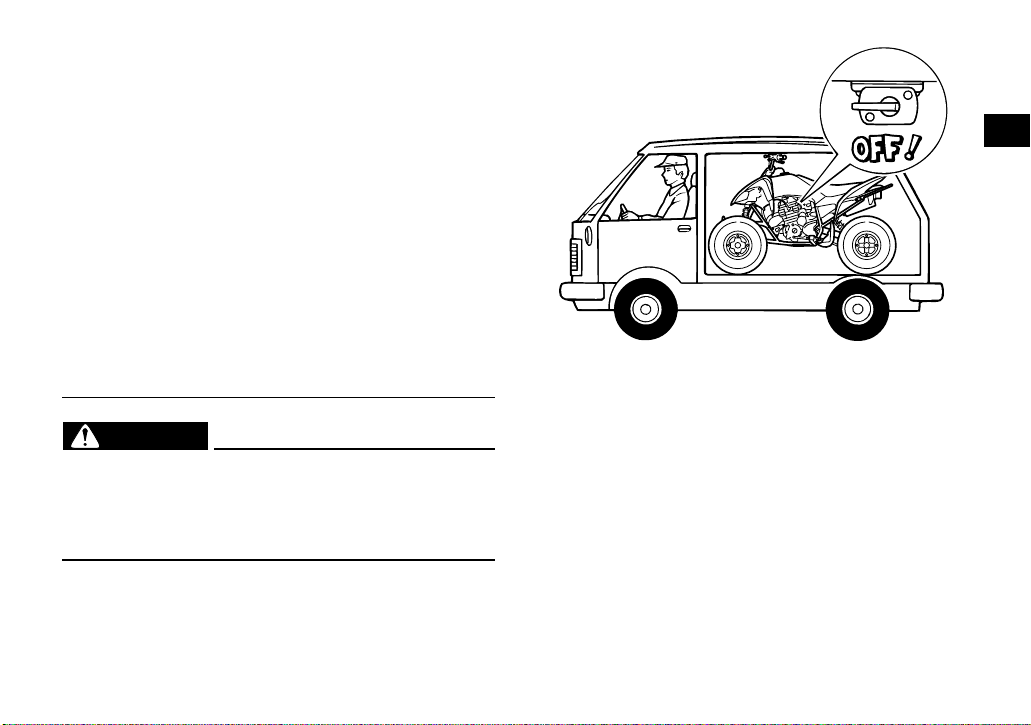
WARNING
When transporting the ATV in another vehicle,
be sure it is kept upright and that the fuel cock
is in the “OFF” position. Otherwise, fuel may
leak out of the carburetor or fuel tank.
2
2-4
Page 24
EBU17680
DESCRIPTION
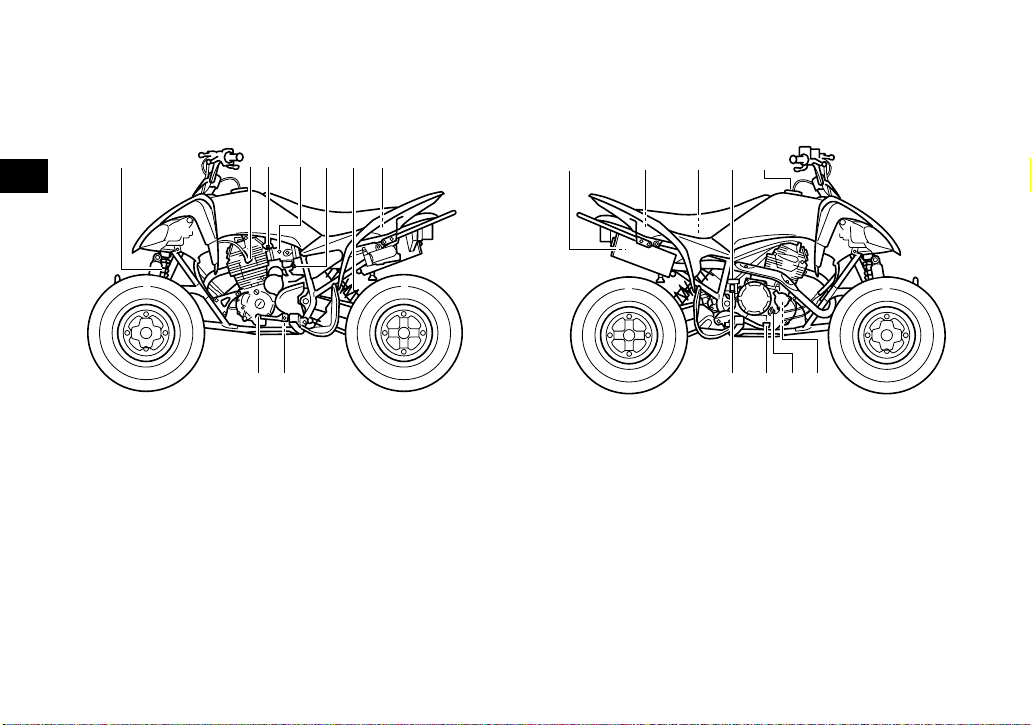
EBU17690
Left view
3
1. Front shock absorber assembly
2. Spark plug
3. Fuel cock
4. Starter (choke)
5. Throttle stop screw
6. Rear shock absorber assembly
7. Owner’s tool kit
8. Engine oil drain bolt
9. Shift pedal
3456 721
9 8
EBU17700
Right view
146
1. Spark arrester
2. Fuse
3. Battery
4. Air filter case
5. Rear brake fluid reservoir
6. Fuel tank cap
7. Oil filter element
8. Engine oil filler cap
9. Brake pedal
10.Rear brake light switch
52,3
8
7910
3-1
Page 25
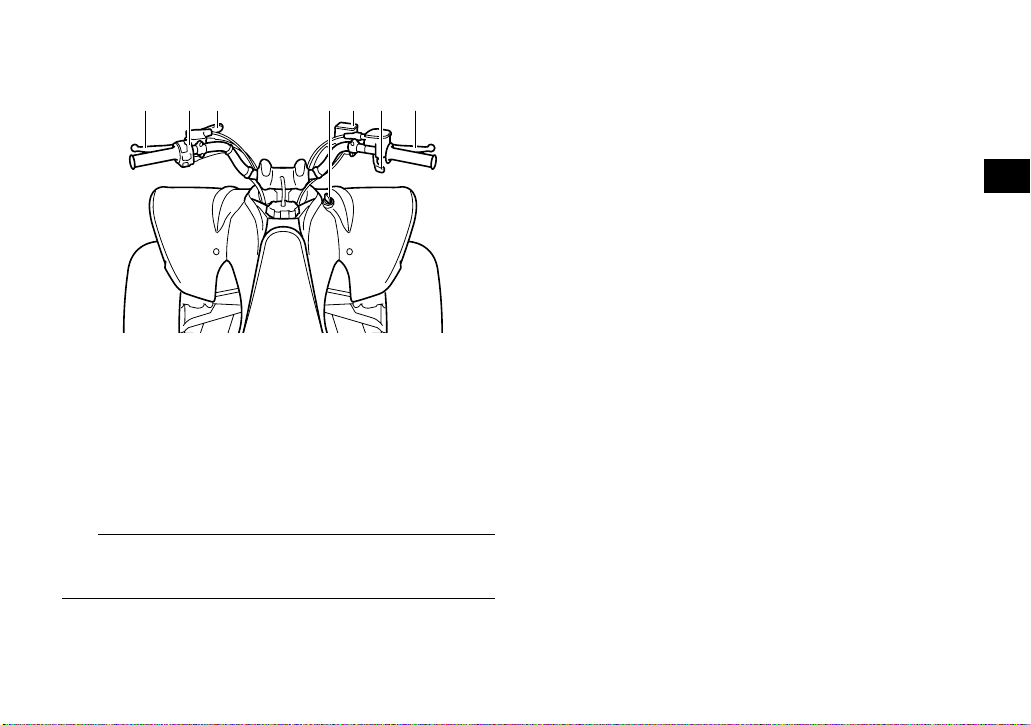
EBU17712
Controls and instruments
1 2 3 4 6 75
1. Clutch lever
2. Handlebar switches
3. Parking brake lever
4. Main switch
5. Front brake fluid reservoir
6. Throttle lever
7. Brake lever
TIP
The ATV you have purchased may differ slightly
from the figures shown in this manual.
3
3-2
Page 26

EBU17733
INSTRUMENT AND CONTROL FUNCTIONS
EBU17760
Main switch
The positions of the main switch are as follows:
OFF ON
ON
All electrical systems are supplied with power. The
4
headlights and taillight come on when the light
switch is on, and the engine can be started. The
key cannot be removed.
OFF
All electrical systems are off. The key can be removed.
1
1. Main switch
4-1
Page 27
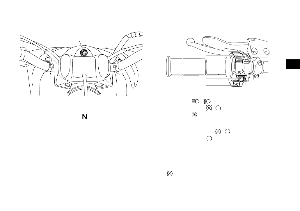
EBU17783
Indicator light
EBU18061
Handlebar switches
1
1
4
2
3
1. Neutral indicator light “N”
EBU17860
Neutral indicator light “”
This indicator light comes on when the transmission is in the neutral position.
1. Light switch “ //OFF”
2. Engine stop switch “ / ”
3. Start switch “”
EBU18080
Engine stop switch “ / ”
Set this switch to “” before starting the engine.
The engine stop switch controls the ignition and
stops the engine when it is running. Use this switch
to stop the engine in an emergency situation. The
engine will not start or run when this switch is set
to “”.
4-2
Page 28
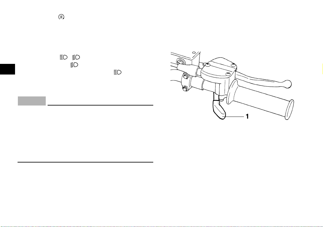
EBU18101
Start switch “”
Push this switch to crank the engine with the starter. See the starting instructions on page 6-1 prior
to starting the engine.
EBU18152
Light switch “ //OFF”
Set this switch to “” to turn on the low beams
4
and the taillight. Set the switch to “” to turn on
the high beams and the taillight. Set the switch to
“OFF” to turn off all the lights.
ECB00041
NOTICE
Do not use the headlights with the engine
turned off for an extended period of time, otherwise the battery may discharge to the point
that the starter motor will not operate properly.
If this should happen, remove the battery and
recharge it. See page 8-35 for battery charging
information.
EBU18282
Throttle lever
Once the engine is running, pushing the throttle lever will increase the engine speed.
Regulate the speed of the ATV by varying the
throttle position. Because the throttle is springloaded, the ATV will decelerate, and the engine will
return to an idle any time the throttle lever is released.
1. Throttle lever
Before starting the engine, check the throttle to be
sure it is operating smoothly. Make sure it returns
to the idle position as soon as the lever is released.
4-3
Page 29
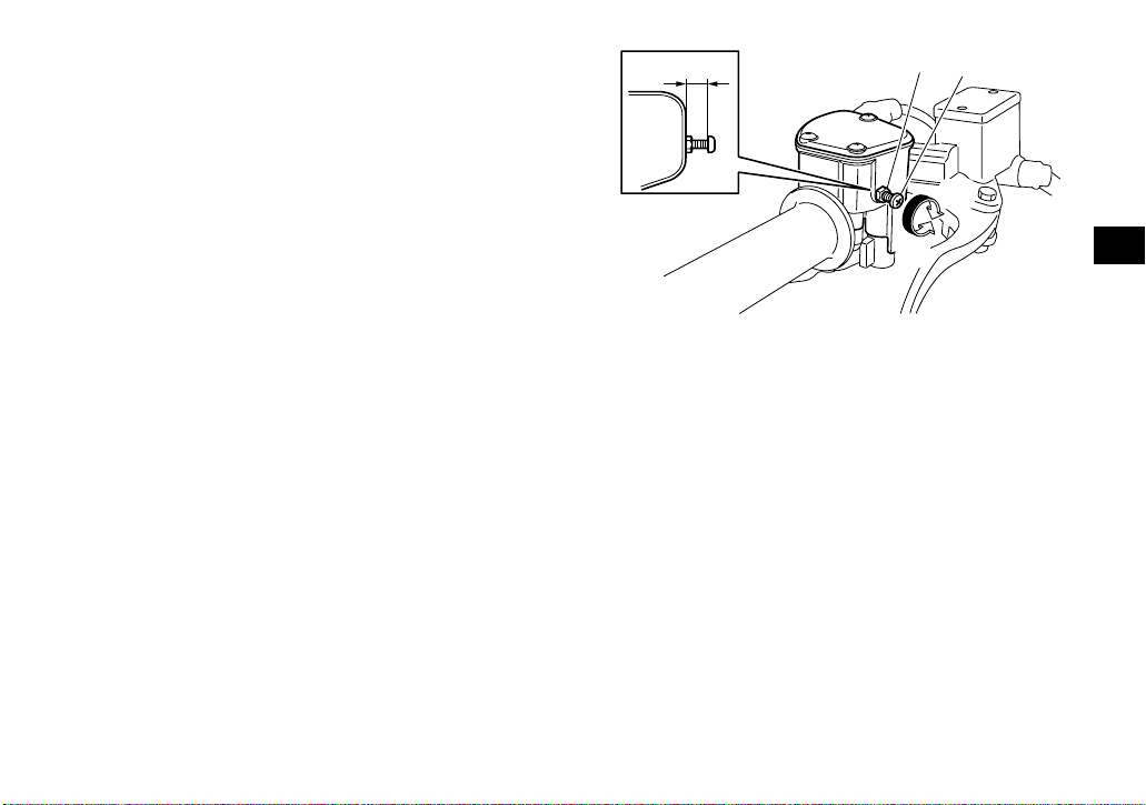
EBU18323
Speed limiter
Your ATV is equipped with an adjustable speed
limiter. The speed limiter keeps the throttle from
fully opening, even when the throttle lever is
pushed to the maximum.
1. Loosen the locknut.
2. To increase the maximum engine power avail-
able and the maximum speed of the ATV, turn
the adjusting screw in direction (a). To decrease the maximum engine power available
and the maximum speed of the ATV, turn the
adjusting screw in direction (b). Do not turn
the adjusting screw out more than 12 mm
(0.47 in) or the throttle cable could be damaged. Always make sure the throttle lever free
play is adjusted to 2.0–4.0 mm (0.08–0.16 in).
(See page 8-21.) WARNING! Improper ad-
justment of the speed limiter and throttle
could cause throttle cable damage or improper throttle operation. You could lose
control, resulting in an accident.
[EWB00241]
1
3
2
(b)
(a)
1. Locknut
2. Adjusting screw
3. No more than 12 mm (0.47 in)
3. Tighten the locknut.
EBU18382
Clutch lever
The clutch lever is located on the left handlebar
and the ignition circuit cut-off system is incorporated in the clutch lever holder. To disengage the
clutch, pull the clutch lever toward the handlebar
grip. To engage the clutch, release the clutch lever.
The clutch lever should be pulled rapidly and released slowly for smooth clutch operation. (See
page 6-1 for a description of the ignition circuit cutoff system.)
4-4
4
Page 30
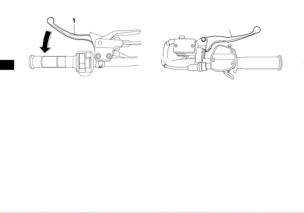
1
4
1. Clutch lever
EBU18411
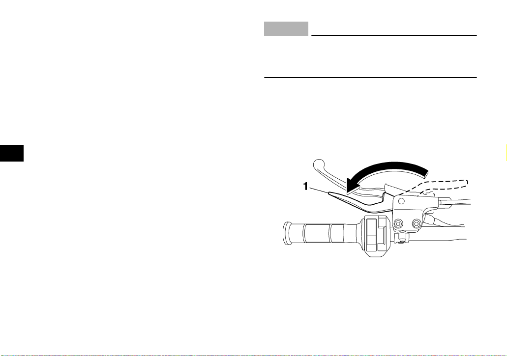
Brake lever (YFM25RA/YFM250RA)
The brake lever is located at the right handlebar
grip. To apply the front brake, pull the brake lever
toward the handlebar grip.
1. Brake lever
EBU18423
Brake lever (YFM25RSEA/YFM250RSEA)
The brake lever is located on the right handlebar.
To apply the front brake, pull the brake lever toward the handlebar grip.
The brake lever is equipped with a position adjusting bolt. To adjust the distance between the brake
lever and the handlebar grip, hold the brake lever
away from the handlebar so it does not contact the
adjusting bolt, loosen the locknut, turn the adjusting bolt, and then tighten the locknut.
4-5
Page 31

3
2
1
1
4
4
1. Brake lever
2. Locknut
3. Brake lever position adjusting bolt
4. Distance between brake lever and handlebar grip
EBU18432
Brake pedal
The brake pedal is located on the right side of the
ATV. To apply the rear brake, push down on the
brake pedal.
1. Brake pedal
EBU18520
Parking brake lever
Use the parking brake before starting the engine or
parking the ATV, especially on a slope. To apply
the parking brake, move the parking brake lever in
direction (a). To release the parking brake, move
the parking brake lever in direction (b).
4-6
Page 32

4
1. Parking brake lever (locked position)
1. Parking brake lever (unlocked position)
EWB00220
WARNING
● Always set the parking brake before starting
the engine. The ATV could start moving unexpectedly if the parking brake is not applied. This could cause loss of control or a
collision.
● Always be sure you have released the park-
ing brake before you begin to ride. The brake
could overheat if you ride the ATV without releasing the parking brake. You could lose
braking performance which could cause an
accident. You could also wear out the brakes
prematurely.
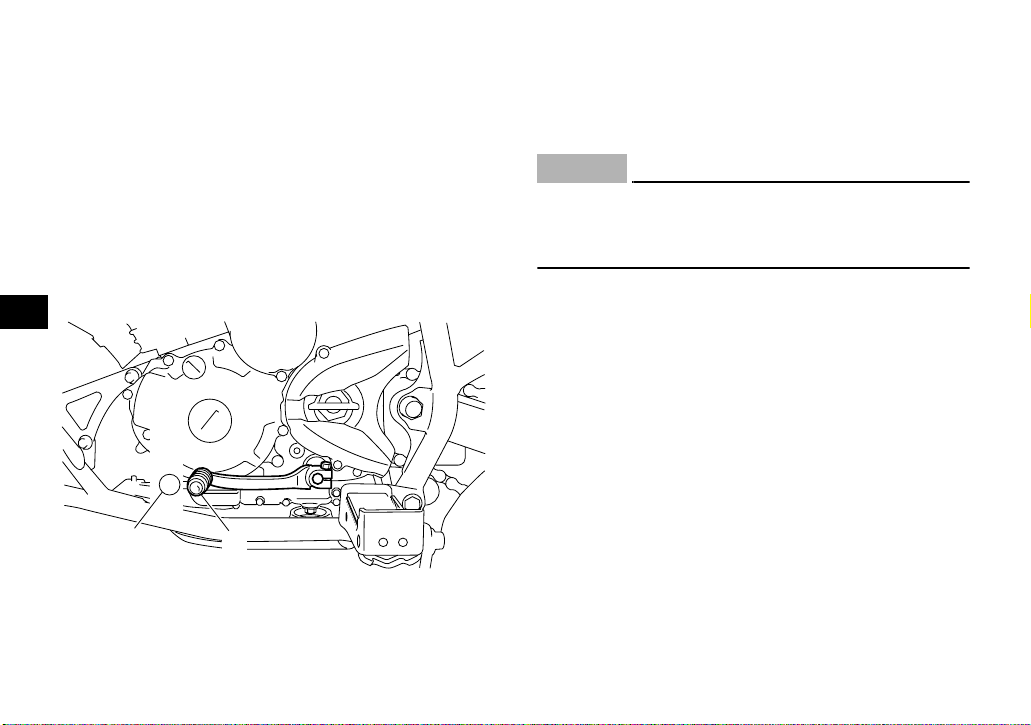
EBU18530
Shift pedal
This ATV is equipped with a constant-mesh 5speed transmission. The shift pedal is located on
the left side of the engine and is used in combination with the clutch when shifting.
4-7
Page 33

1
4
1
1. Shift pedal
EBU18720
Fuel tank cap
Remove the fuel tank cap by turning it counterclockwise.
1. Fuel tank cap
EBU18754
Fuel
Make sure there is sufficient gasoline in the tank.
EWB02521
WARNING
Gasoline and gasoline vapors are extremely
flammable. To avoid fires and explosions and
to reduce the risk of injury when refueling, follow these instructions.
1. Before refueling, turn off the engine and be
sure that no one is sitting on the vehicle. Never refuel while smoking, or while in the vicinity
4-8
Page 34

of sparks, open flames, or other sources of ignition such as the pilot lights of water heaters
and clothes dryers.
2. Do not overfill the fuel tank. When refueling,
be sure to insert the pump nozzle into the fuel
tank filler hole. Stop filling when the fuel reaches the bottom of the filler tube. Because fuel
4
expands when it heats up, heat from the engine or the sun can cause fuel to spill out of
the fuel tank.
1. Maximum fuel level
2. Filler tube
Recommended fuel:
UNLEADED GASOLINE ONLY
For Europe: Regular unleaded gasoline only
with a research octane number of 91 or
higher
Fuel tank capacity:
9.0 L (2.38 US gal, 1.98 Imp.gal)
Fuel reserve amount:
1.0 L (0.26 US gal, 0.22 Imp.gal)
3. Wipe up any spilled fuel immediately.
NOTICE: Immediately wipe off spilled fuel
with a clean, dry, soft cloth, since fuel may
deteriorate painted surfaces or plastic
parts.
[ECB00981]
4. Turn the fuel tank cap fully clockwise to make
sure it is securely closed.
EWB02531
WARNING
Gasoline is poisonous and can cause injury or
death. Handle gasoline with care. Never siphon
gasoline by mouth. If you should swallow
some gasoline or inhale a lot of gasoline vapor,
or get some gasoline in your eyes, see your
4-9
Page 35
doctor immediately. If gasoline spills on your
skin, wash with soap and water. If gasoline
spills on your clothing, change your clothes.
ECB00070
NOTICE
Use only unleaded gasoline. The use of leaded
gasoline will cause severe damage to internal
engine parts, such as the valves and piston
rings, as well as to the exhaust system.
Your Yamaha engine has been designed to use
regular unleaded gasoline with a research octane
number of 91 or higher. If knocking (or pinging) occurs, use a gasoline of a different brand. Use of unleaded fuel will extend spark plug life and reduce
maintenance costs.
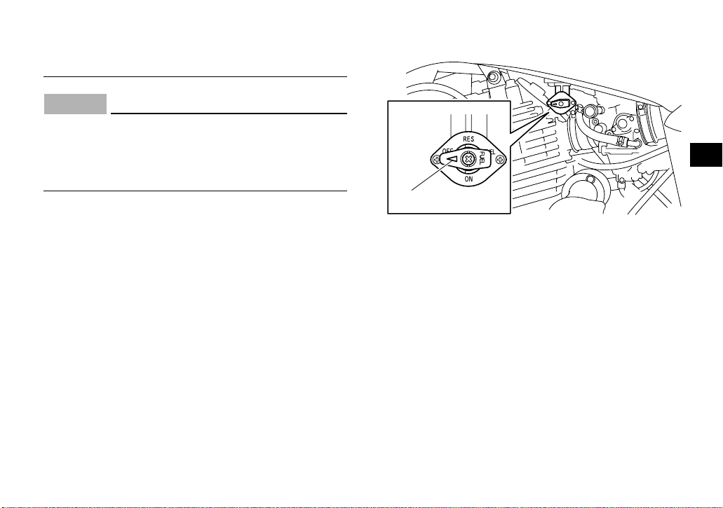
EBU18820
Fuel cock
The fuel cock supplies fuel from the tank to the carburetor while also filtering it.
The fuel cock lever positions are explained as follows and shown in the illustrations.
OFF
OFF
1
1. Arrow mark positioned over “OFF”
With the fuel cock lever in this position, fuel will not
flow. Always turn the fuel cock lever to this position
when the engine is not running.
4
4-10
Page 36

ON
RES
4
ON
1. Arrow mark positioned over “ON”
1
With the fuel cock lever in this position, fuel flows
to the carburetor. Turn the fuel cock lever to this
position when starting the engine and riding.
RES
1. Arrow mark positioned over “RES”
1
This indicates reserve. With the fuel cock lever in
this position, the fuel reserve is made available.
Turn the fuel cock lever to this position if you run
out of fuel while riding. When this occurs, refuel as
soon as possible and be sure to turn the fuel cock
lever back to “ON”!
EBU18840
Starter (choke)
Starting a cold engine requires a richer air-fuel mixture, which is supplied by the starter (choke).
Move the starter (choke) in direction (a) to turn on
the starter (choke).
4-11
Page 37

Move the starter (choke) in direction (b) to turn off
the starter (choke).
See the “Starting a cold engine” section on page
6-1 for proper operation.
1
(b)
(a)
1. Starter (choke)
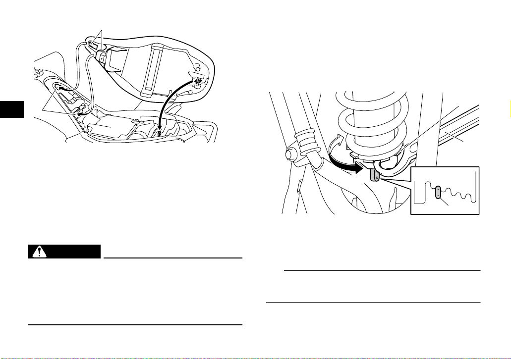
EBU18891
Seat
To remove the seat
Insert your hand between the rear of the seat and
the rear fender, pull the seat lock lever upward and
pull up the seat at the rear.
1
4
1. Seat lock lever
To install the seat
Insert the projections on the front of the seat into
the seat holders and push down on the seat at the
rear. Make sure that the seat is securely fitted.
4-12
Page 38
1
Adjust the spring preload as follows.
Turn the spring preload adjusting ring in direction
(a) to increase the spring preload and thereby
harden the suspension, and in direction (b) to decrease the spring preload and thereby soften the
suspension.
4
2
1. Projection
2. Seat holder
EBU18992
Adjusting the front shock absorber assemblies (YFM25RA/YFM250RA)
The spring preload can be adjusted to suit the rider’s weight and the riding conditions.
EWB00400
WARNING
Always adjust the shock absorber assemblies
on the left and right side to the same setting.
Uneven adjustment can cause poor handling
and loss of stability, which could lead to an accident.
(a)
(b)
1. Spring preload adjusting ring
2. Special wrench
3. Position indicator
TIP
A special wrench can be obtained at a Yamaha
dealer to make this adjustment.
4-13
1
1
2
2
3
4
5
3
Page 39

Spring preload setting:
Minimum (soft):
1
Standard:
2
Maximum (hard):
5
EBU30050
Adjusting the front shock absorber assemblies (YFM25RSEA/YFM250RSEA)
These shock absorber assemblies are equipped
with a spring preload adjusting nut, a rebound
damping force adjusting screw, with a compression damping force adjusting bolt (for fast compression damping), and a compression damping
force adjusting screw (for slow compression damping).
EWB02491
WARNING
● Suspension components become hot during
operation. Never touch the compression
damping force adjusting bolt and screw, the
rebound damping force adjusting screw or
the oil reservoir with your bare hand or skin
until suspension components have cooled.
● Always adjust the shock absorber assem-
blies on the left and right side to the same
setting. Uneven adjustment can cause poor
handling and loss of stability, which could
lead to an accident.
ECB00090
NOTICE
Never turn an adjusting mechanism beyond
the minimum and maximum settings.
TIP
Although the total number of clicks or turns of a
damping force adjusting mechanism may not exactly match the following specifications due to
small differences in production, the actual number
of clicks or turns always represents the entire adjusting range. To obtain a precise adjustment, it
would be advisable to check the number of clicks
or turns of each damping force adjusting mechanism and to modify the specifications as necessary.
Spring preload
1. Loosen the locknut.
4-14
4
Page 40

2. Turn the spring preload adjusting nut in direction (a) to increase the spring preload and
thereby harden the suspension, and in direction (b) to decrease the spring preload and
thereby soften the suspension.
2
4
(a)
1
(b)
1. Spring preload adjusting nut
2. Locknut
3. Special wrench
TIP
● A special wrench can be obtained at a Yamaha
dealer to make this adjustment.
● The spring preload setting is determined by
measuring distance A, shown in the illustration.
The shorter distance A is, the higher the spring
preload; the longer distance A is, the lower the
spring preload. With each complete turn of the
adjusting nut, distance A is changed by 1.5 mm
(0.06 in).
Spring preload setting:
Minimum (soft):
Distance A = 209.6 mm (8.25 in)
Standard:
Distance A = 206.0 mm (8.11 in)
Maximum (hard):
3
Distance A = 197.6 mm (7.78 in)
1
1. Distance A
4-15
Page 41

3. Tighten the locknut to the specified torque.
NOTICE: Always tighten the locknut
against the adjusting nut, and then tighten
it to the specified torque.
[ECB00081]
Tightening torque:
Locknut:
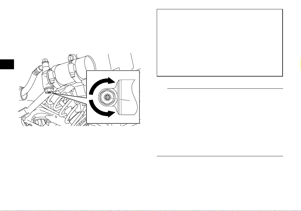
42 Nm (4.2 m·kgf, 30 ft·lbf)
Rebound damping force
Turn the rebound damping force adjusting screw in
direction (a) to increase the rebound damping
force and thereby harden the damping, and in direction (b) to decrease the rebound damping force
and thereby soften the damping.
1
(b)
1. Rebound damping force adjusting screw
Rebound damping setting:
Minimum (soft):
20 click(s) in direction (b)*
Standard:
12 click(s) in direction (b)*
Maximum (hard):
3 click(s) in direction (b)*
* With the adjusting screw fully turned in di-
rection (a)
4-16
4
(a)
Page 42

Compression damping force
Compression damping force (for fast compression
damping)
To increase the compression damping force and
thereby harden the compression damping, turn the
compression damping force adjusting bolt in direction (a). To decrease the compression damping
4
force and thereby soften the compression damping, turn the adjusting bolt in direction (b).
(a)
(b)
1. Compression damping force adjusting bolt (for fast
compression damping)
Compression damping setting (for fast compression damping):
Minimum (soft):
4 turn(s) out from the fully turned in position
Standard:
2 turn(s) out from the fully turned in position
Maximum (hard):
Adjusting bolt fully turned in
Compression damping force (for slow compression damping)
To increase the compression damping force and
thereby harden the compression damping, turn the
1
compression damping force adjusting screw in direction (a). To decrease the compression damping
force and thereby soften the compression damping, turn the adjusting screw in direction (b).
4-17
Page 43

(a)
(b)
1. Compression damping force adjusting screw (for slow
compression damping)
Compression damping setting (for slow compression damping):
Minimum (soft):
16 click(s) in direction (b)*
Standard:
10 click(s) in direction (b)*
Maximum (hard):
1 click(s) in direction (b)*
* With the adjusting screw fully turned in di-
rection (a)
EWB00410
WARNING
These shock absorber assemblies contain
highly pressurized nitrogen gas. Read and understand the following information before handling the shock absorber assemblies.
1
● Do not tamper with or attempt to open the
cylinder assemblies.
● Do not subject the shock absorber assem-
4
blies to an open flame or other high heat
source. This may cause the unit to explode
due to excessive gas pressure.
● Do not deform or damage the cylinders in
any way. Cylinder damage will result in poor
damping performance.
● Do not dispose of a damaged or worn out
shock absorber assembly yourself. Take the
shock absorber assembly to a Yamaha dealer for any service.
EBU28243
Adjusting the rear shock absorber assembly (YFM25RA/YFM250RA)
The spring preload can be adjusted to suit the rider’s weight and the riding conditions.
4-18
Page 44

ECB01090
NOTICE
Never turn the adjusting mechanism beyond
the minimum and maximum settings.
Adjust the spring preload as follows.
1. Loosen the locknut.
2. Turn the spring preload adjusting nut in direc-
4
tion (a) to increase the spring preload and
thereby harden the suspension, and in direction (b) to decrease the spring preload and
thereby soften the suspension.
3
(b)
1. Locknut
2. Spring preload adjusting nut
3. Distance A
(a)
2
1
TIP
● A special wrench can be obtained at a Yamaha
dealer to make this adjustment.
● The spring preload setting is determined by
measuring distance A, shown in the illustration.
The shorter distance A is, the higher the spring
preload; the longer distance A is, the lower the
spring preload. With each complete turn of the
adjusting nut, distance A is changed by 1.0 mm
(0.04 in).
Spring preload setting:
Minimum (soft):
Distance A = 234.0 mm (9.21 in)
Standard:
Distance A = 230.0 mm (9.06 in)
Maximum (hard):
Distance A = 222.0 mm (8.74 in)
3. Tighten the locknut to the specified torque.
NOTICE: Always tighten the locknut
against the adjusting nut, and then tighten
it to the specified torque.
[ECB00081]
4-19
Page 45

Tightening torque:
Locknut:
42 Nm (4.2 m·kgf, 30 ft·lbf)
EWB00450
WARNING
This shock absorber assembly contains highly
pressurized nitrogen gas. If the shock absorber assembly is damaged, it could explode
causing injury or property damage. Shock absorber cylinder damage could also result in
poor handling which could cause an accident.
● Do not tamper with or attempt to open the
cylinder assembly.
● Do not subject the shock absorber assembly
to an open flame or other high heat.
● Do not deform or damage the cylinder in any
way.
● Do not dispose of a damaged or worn out
shock absorber assembly yourself. Take the
shock absorber assembly to a Yamaha dealer for any service.
EBU29312
Adjusting the rear shock absorber assembly (YFM25RSEA/YFM250RSEA)
The spring preload, rebound damping and compression damping forces of the rear shock absorber assembly can be adjusted to suit the rider’s
weight and the riding conditions.
EWB02500
WARNING
Suspension components become hot during
operation. Never touch the compression
damping force adjusting screw, the rebound
damping force adjusting dial or the oil reservoir with your bare hand or skin until suspension components have cooled.
ECB00090
NOTICE
Never turn an adjusting mechanism beyond
the minimum and maximum settings.
Spring preload
1. Loosen the locknut.
4
4-20
Page 46

2. Turn the spring preload adjusting nut in direction (a) to increase the spring preload and
thereby harden the suspension, and in direction (b) to decrease the spring preload and
thereby soften the suspension.
4
2
(a)
(b)
1
1. Locknut
2. Spring preload adjusting nut
TIP
● A special wrench can be obtained at a Yamaha
dealer to make this adjustment.
● The spring preload setting is determined by
measuring distance A, shown in the illustration.
The shorter distance A is, the higher the spring
preload; the longer distance A is, the lower the
spring preload. With each complete turn of the
adjusting nut, distance A is changed by 1.5 mm
(0.06 in).
Spring preload setting:
Minimum (soft):
Distance A = 232.0 mm (9.13 in)
Standard:
Distance A = 228.0 mm (8.98 in)
Maximum (hard):
Distance A = 220.0 mm (8.66 in)
1
1. Distance A
4-21
Page 47

3. Tighten the locknut to the specified torque.
NOTICE: Always tighten the locknut
against the adjusting nut, and then tighten
it to the specified torque.
[ECB00081]
Tightening torque:
Locknut:
42 Nm (4.2 m·kgf, 30 ft·lbf)
Rebound damping force
Turn the rebound damping force adjusting dial in
direction (a) to increase the rebound damping
force and thereby harden the damping, and in direction (b) to decrease the rebound damping force
and thereby soften the damping.
1
1. Rebound damping force adjusting dial
Rebound damping setting:
Minimum (soft):
20 click(s) in direction (b)*
Standard:
12 click(s) in direction (b)*
Maximum (hard):
3 click(s) in direction (b)*
* With the adjusting dial fully turned in direc-
tion (a)
4-22
(a)
4
(b)
Page 48
Compression damping force
Turn the compression damping force adjusting
screw in direction (a) to increase the compression
damping force and thereby harden the damping,
and in direction (b) to decrease the compression
damping force and thereby soften the damping.
4
(a)
(b)
1. Compression damping force adjusting screw
Compression damping setting:
Minimum (soft):
12 click(s) in direction (b)*
Standard:
7 click(s) in direction (b)*
Maximum (hard):
2 click(s) in direction (b)*
* With the adjusting screw fully turned in di-
rection (a)
TIP
Although the total number of clicks of a damping
1
force adjusting mechanism may not exactly match
the above specifications due to small differences in
production, the actual number of clicks always represents the entire adjusting range. To obtain a precise adjustment, it would be advisable to check the
number of clicks of each damping force adjusting
mechanism and to modify the specifications as
necessary.
4-23
Page 49

EWB00430
WARNING
This shock absorber assembly contains highly
pressurized nitrogen gas. Read and understand the following information before handling the shock absorber assembly.
● Do not tamper with or attempt to open the
cylinder assembly.
● Do not subject the shock absorber assembly
to an open flame or other high heat source.
This may cause the unit to explode due to excessive gas pressure.
● Do not deform or damage the cylinder in any
way. Cylinder damage will result in poor
damping performance.
● Do not dispose of a damaged or worn out
shock absorber assembly yourself. Take the
shock absorber assembly to a Yamaha dealer for any service.
4
4-24
Page 50

EBU19201
PRE-OPERATION CHECKS
EBU19224
Inspect your vehicle each time you use it to make sure the vehicle is in safe operating condition. Always
follow the inspection and maintenance procedures and schedules described in the Owner’s Manual.
EWB00481
WARNING
Failure to inspect or maintain the vehicle properly increases the possibility of an accident or equipment damage. Do not operate the vehicle if you find any problem. If a problem cannot be corrected
5
by the procedures provided in this manual, have the vehicle inspected by a Yamaha dealer.
Before using this vehicle, check the following points:
ITEM ROUTINE PAGE
Fuel
Engine oil
Front brake
• Check fuel level in fuel tank, and add recommended fuel if necessary.
• Check fuel line for leakage. Correct if necessary.
• Check oil level in engine, and add recommended oil to specified lev-
el if necessary.
• Check ATV for oil leakage. Correct if necessary.
• Check operation. If soft or spongy, have Yamaha dealer bleed hy-
draulic system.
• Check brake pads for wear, and replace if necessary.
• Check brake fluid level in reservoir, and add recommended brake
fluid to specified level if necessary.
• Check hydraulic system for leakage. Correct if necessary.
4-8, 5-3
5-3, 8-11
5-3, 8-22, 8-23, 8-25
5-1
Page 51

ITEM ROUTINE PAGE
• Check operation. If soft or spongy, have Yamaha dealer bleed hydraulic system.
Rear brake
Clutch
Throttle lever
Control cables • Make sure that operation is smooth. Lubricate if necessary. 8-31
Drive chain
Wheels and tires
Shift pedal
Brake pedal
Brake and clutch levers
Chassis fasteners • Make sure that all nuts, bolts and screws are properly tightened. 5-6
Instruments, lights and
switches
• Check brake pads for wear, and replace if necessary.
• Check brake fluid level in reservoir, and add recommended brake
fluid to specified level if necessary.
• Check hydraulic system for leakage. Correct if necessary.
• Check operation, and correct if necessary.
• Lubricate cable if necessary.
• Check lever free play, and adjust if necessary.
• Make sure that operation is smooth. Lubricate cable and lever hous-
ing if necessary.
• Check cable free play, and adjust if necessary.
• Check chain slack, and adjust if necessary.
• Check chain condition. Lubricate if necessary.
• Check wheel condition, and replace if damaged.
• Check tire condition and tread depth. Replace if necessary.
• Check air pressure. Correct if necessary.
• Make sure that operation is smooth.
• Correct if necessary.
• Make sure that operation is smooth. Lubricate pedal pivoting point if
necessary.
• Make sure that operation is smooth. Lubricate lever pivoting points if
necessary.
• Check operation, and correct if necessary. 5-6
5-3, 8-22, 8-23, 8-25
8-28
5-3, 8-21
5-4, 8-29, 8-31
5-4
8-33
8-33
8-32
5
5-2
Page 52

EBU19541
Fuel
Make sure that there is sufficient fuel in the tank.
(See page 4-8.)
EBU19560
Engine oil
Make sure that the engine oil is at the specified level. Add oil as necessary. (See page 8-11.)
EBU19711
5
Front and rear brakes
Brake lever and brake pedal
● Check that there is no free play in the brake le-
ver. If there is free play, have a Yamaha dealer
check the brake system.
● Check for correct brake pedal height. (See page
8-25.) If the pedal height is incorrect, have a
Yamaha dealer adjust it.
● Check the operation of the lever and pedal. They
should move smoothly and there should be a
firm feeling when the brakes are applied. If not,
have a Yamaha dealer check the brake system.
Brake fluid level
Check the brake fluid level. Add fluid if necessary.
(See page 8-23.)
Recommended brake fluid:
DOT 4
Brake fluid leakage
Check to see if any brake fluid is leaking out of the
pipe joints or brake fluid reservoirs. Apply the
brakes firmly for one minute. If there is any leakage, have a Yamaha dealer check the brake system.
Brake operation
Test the brakes at slow speed after starting out to
make sure they are working properly. If the brakes
do not provide proper braking performance, check
the brake pads for wear. (See page 8-22.)
EBU19761
Throttle lever
Check the operation of the throttle lever. It must
open smoothly and spring back to the idle position
when released. Have a Yamaha dealer correct if
necessary.
5-3
Page 53

EBU19770
Drive chain
Check the condition of the drive chain and check
the drive chain slack. Lubricate and adjust the
drive chain as necessary. (See page 8-29.)
EBU19794
Tires
Check tire pressure regularly to make sure it is at
the recommended specifications. Also check for
wear and damage.
Tire pressure
Use the low-pressure tire gauge to check and adjust tire pressures when the tires are cold. Tire
pressures must be equal on both sides.
WARNING! Operation of this vehicle with improper tire pressure may cause severe injury
or death from loss of control or rollover. Tire
pressure below the minimum specified could
also cause the tire to dislodge from the rim under severe riding conditions.
pressures to the following specifications:
[EWB02541] Set tire
Recommended tire pressure:
Front
27.5 kPa (0.275 kgf/cm², 4.0 psi)
Rear
27.5 kPa (0.275 kgf/cm², 4.0 psi)
Minimum tire pressure:
Front
24.5 kPa (0.245 kgf/cm², 3.6 psi)
Rear
24.5 kPa (0.245 kgf/cm², 3.6 psi)
Maximum tire seating pressure:
Front
250 kPa (2.5 kgf/cm², 36 psi)
Rear
250 kPa (2.5 kgf/cm², 36 psi)
The low-pressure tire gauge is included as standard equipment. Make two measurements of the
tire pressure and use the second reading. Dust or
dirt in the gauge could cause the first reading to be
incorrect.
5
5-4
Page 54

5
1. Low-pressure tire gauge 1. Tire wear limit
Tire wear limit
When the tire groove decreases to 3 mm (0.12 in)
due to wear, replace the tire.
Tire information
This ATV is equipped with tubeless tires with
valves.
EWB02551
WARNING
Use of improper tires on this ATV may cause
loss of control, increasing your risk of an accident.
After extensive tests, only the tires listed below
have been approved for this model by Yamaha
Motor Co., Ltd.
5-5
Page 55

Front:
Manufacturer/model:
DUNLOP/KT201
Size:
AT20 x 7-10
Ty p e:
Tu b el e ss
Rear:
Manufacturer/model:
DUNLOP/KT205A
Size:
AT19 x 10-9
Ty p e:
Tu b el e ss
Aftermarket tires and rims
The tires and rims that came with your ATV were
designed to match the performance capabilities
and to provide the best combination of handling,
braking, and comfort. Other tires, rims, sizes, and
combinations may not be appropriate.
EBU19840
Chassis fasteners
Make sure that all nuts, bolts and screws are properly tightened.
EBU19850
Instruments, lights and switches
Check that all instruments, lights and switches are
working properly. Correct if necessary.
5
5-6
Page 56

EBU19881
OPERATION
EBU19901
Read the Owner’s Manual carefully before riding
the ATV. If there is a control or function you do not
understand, ask your Yamaha dealer.
EWB00631
WARNING
Read the Owner’s Manual carefully to become
familiar with all controls in order to help pre-
6
vent any loss of control, which could cause an
accident or injury.
EBU20183
Starting a cold engine
ECB00150
NOTICE
See the “Engine break-in” section on page 6-4
prior to operating the engine for the first time.
1. Set the parking brake.
2. Turn the fuel cock to “ON”.
3. Turn the key to “ON” and the engine stop
switch to “”.
4. Shift the transmission into neutral. The neutral
indicator light should come on. If the indicator
light does not come on, have a Yamaha dealer check the electrical circuit.
TIP
This model is equipped with an ignition circuit cutoff system. The engine can be started under the
following conditions.
● The transmission is in neutral.
● The clutch is disengaged with the transmission
in gear. However, it is recommended to shift into
neutral before starting the engine.
5. Use the starter (choke) in reference to the figure:
Position (1):
Cold engine start with ambient temperature
below 5 °C (40 °F).
Position (2):
Cold engine start with ambient temperature
between 0 °C (30 °F) and 30 °C (90 °F).
Position (3):
Cold engine start with ambient temperature
above 25 °C (80 °F).
6-1
Page 57

Ambient temp./starter (choke) position
1
3
2
4
123
1. Fully open
2. Half open
3. Closed
4. Starter (choke)
6. Completely close the throttle lever and start
the engine by pushing the start switch.
NOTICE: For maximum engine life, never
accelerate hard when the engine is cold!
[ECB00162]
TIP
If the engine fails to start, release the start switch,
then push it again. Pause a few seconds before
the next attempt. Each cranking should be as short
as possible to preserve battery energy. Do not
crank the engine more than 10 seconds on each
attempt.
7. If the engine is started with the starter (choke)
in position (1), the starter (choke) should be
returned to position (2) to warm up the engine.
If the engine is started with the starter (choke)
in position (2), keep the starter (choke) in this
position to warm up the engine.
8. Continue warming up the engine until it idles
smoothly, then return the starter (choke) to
position (3) before riding.
TIP
The engine is warm when it responds quickly to the
throttle with the starter (choke) turned off.
EBU20291
Starting a warm engine
Follow the same procedure as for starting a cold
engine, with the exception that the starter (choke)
is not required when the engine is warm. Instead,
start the engine with the throttle slightly open.
6
6-2
Page 58
EBU20522
Shifting
This ATV has a 5-speed forward transmission. The
transmission allows you to control the amount of
power you have available at a given speed or for
starting, accelerating, climbing hills, etc.
To shift into neutral, release the throttle lever, apply the clutch, and then repeatedly depress the
shift pedal until it stops.
When it stops, it will be in first gear. Raise the pedal
slightly to reach the neutral position, and then release the clutch.
6
5
4
3
2
N
1
2
1. Shift pedal
2. Neutral position
1
EBU20592
To start out and accelerate
1. Release the throttle lever, apply the front or
rear brake, and then release the parking
brake.
ECB00200
NOTICE
Always close the throttle before shifting gears,
otherwise damage to the engine and drive train
may result.
2. Pull the clutch lever to disengage the clutch.
3. Shift into first gear, and then release the
brake.
4. Open the throttle gradually and at the same
time, release the clutch lever slowly.
WARNING! Opening the throttle abruptly
or releasing the clutch lever too quickly
could make the ATV wheelie, which would
increase the chance of an accident, including an overturn.
[EWB00731]
5. Once the ATV has attained adequate speed,
release the throttle, and at the same time,
quickly pull in the clutch lever.
6. Shift the transmission into second gear.
(Make sure not to shift the transmission into
neutral.)
6-3
Page 59

7. Open the throttle part way and gradually release the clutch lever.
8. Follow the same procedure when shifting to
the next higher gear.
EBU20650
To decelerate
When slowing down or stopping, release the throttle and apply the brakes smoothly and evenly. As
you slow down, shift to a lower gear. Be sure that
the engine has sufficiently slowed before engaging
a lower gear. Improper use of the brakes or shifting
can cause the tires to lose traction, reducing control and increasing the possibility of an accident.
EWB00710
WARNING
Make sure the engine has sufficiently slowed
before shifting to a lower gear. Engaging a lower gear when the engine speed is too high
could make the wheels stop rotating and lose
traction. This could cause loss of control, an
accident and injury. It could also cause engine
or drive train damage.
ECB00180
NOTICE
● Even with the transmission in the neutral po-
sition, do not coast for long periods of time
with the engine off, and do not tow the ATV
for long distances. The transmission is properly lubricated only when the engine is running. Inadequate lubrication may damage
the transmission.
● Always use the clutch when changing gears.
The engine, transmission and drive train are
not designed to withstand the shock of
forced shifting and can be damaged by shifting without using the clutch.
EBU20672
Engine break-in
TIP
● For ATVs equipped with an odometer or an hour
meter, follow the figures given in km (mi) or the
figures given in hours.
● For ATVs not equipped with an odometer or
hour meter, follow the figures given in hours.
6
6-4
Page 60
There is never a more important period in the life of
your engine than the first 320 km (200 mi) or 20
hours of riding. For this reason, you should read
the following material carefully.
Since the engine is brand new, do not put an excessive load on it for the first 320 km (200 mi) or 20
hours. The various parts in the engine wear and
polish themselves to the correct operating clearances. During this period, prolonged full-throttle
operation or any condition that might result in engine overheating must be avoided.
6
0–160 km (0–100 mi) or 0–10 hours
Avoid prolonged operation above 1/2 throttle. Vary
the speed of the ATV regularly. Do not operate it at
one set throttle position.
160–320 km (100–200 mi) or 10–20 hours
Avoid prolonged operation above 3/4 throttle. Rev
the engine through the gears freely, but do not use
full throttle at any time.
ECB00220
NOTICE
If any engine trouble should occur during the
engine break-in period, immediately have a
Yamaha dealer check the ATV.
EBU20722
Parking
When parking the ATV, shift into first gear, stop the
engine, apply the parking brake, and then turn the
fuel cock to “OFF”.
320 km (200 mi) or 20 hours and beyond
The ATV can now be operated normally.
1. Parking brake lever (locked position)
6-5
Page 61

EBU20865
Parking on a slope
EWB00851
WARNING
Avoid parking on hills or other inclines. Parking on a hill or other incline could cause the
ATV to roll out of control, increasing the
chance of an accident. If you must park on an
incline, place the ATV transversely across the
incline, shift into first gear, stop the engine, apply the parking brake, and then block the front
and rear wheels with rocks or other objects.
Never park the ATV on hills that are too steep
to walk up easily.
EBU20910
Accessories and loading
6
1. Bring the ATV to a stop by applying the front
brake, shift into first gear, and then stop the
engine.
2. With the front and rear brakes applied, apply
the parking brake.
3. Release the front and rear brakes.
4. Turn the fuel cock to “OFF”.
EBU20921
Genuine Yamaha Accessories
Choosing accessories for your ATV is an important
decision. Genuine Yamaha Accessories, which
are available only from a Yamaha dealer, have
been designed, tested, and approved by Yamaha
for use on your ATV. Many companies with no connection to Yamaha manufacture parts and accessories or offer other modifications for Yamaha
vehicles. Yamaha is not in a position to test the
products that these aftermarket companies produce. Therefore, Yamaha can neither endorse nor
6-6
Page 62

recommend the use of accessories not sold by
Yamaha or modifications not specifically recommended by Yamaha, even if sold and installed by
a Yamaha dealer.
Aftermarket parts, accessories, and modifications
While you may find aftermarket products similar in
design and quality to genuine Yamaha Accessories, recognize that some aftermarket accessories
or modifications are not suitable because of potential safety hazards to you or others. Installing after-
6
market products or having other modifications
performed to your ATV that change any of the vehicle’s design or operation characteristics can put
you and others at greater risk of serious injury or
death. You are responsible for injuries related to
changes in the vehicle.
Keep the following in mind when considering an
accessory or operating an ATV which has accessories.
● Accessories should be rigidly and securely
mounted. An accessory which can shift position
or come off while you are riding could affect your
ability to control the ATV.
● Do not mount an accessory where it could inter-
fere with your ability to control the ATV. Examples include (but are not limited to) a heavy or
bulky object attached to the handlebars which
could make steering difficult, an accessory that
limits your ability to move around on the seat, or
one that limits your view.
● Use extra caution when riding an ATV with ac-
cessories. The ATV may handle differently than
it does without accessories.
EBU20941
Loading
EWB00820
WARNING
Never exceed the stated load capacity for this
ATV. Overloading this ATV or carrying or towing cargo improperly could cause changes in
ATV handling which could lead to an accident.
Cargo should be properly distributed and securely attached. Reduce speed when carrying
cargo or pulling a trailer. Allow greater distance for braking.
As originally equipped, this ATV is not designed to
carry cargo or tow a trailer. If you choose to add accessories so that you can carry cargo or tow a trail-
6-7
Page 63

er, you must use common sense and good
judgment as the stability and handling of an ATV
can be changed. When adding accessories, keep
the following points in mind:
● Never exceed the weight limits shown. An over-
loaded ATV can be unstable.
MAXIMUM LOADING LIMIT
ATV loading limit (total weight of rider, cargo,
accessories, and tongue):
100.0 kg (220 lb)
practice not to exceed 2nd gear whenever you
are carrying heavier loads or when towing a trailer.
● Allow more braking distance. A heavier ATV
takes longer to stop.
● Avoid making sharp turns unless at very slow
speeds.
● Avoid hills and rough terrain. Choose terrain
carefully. Added weight affects the stability and
handling of the ATV.
● If you are carrying cargo and towing a trailer, in-
clude the tongue weight in the maximum ATV
load limit.
● Load cargo on the carriers as close to the center
of the ATV as possible. Put cargo at the rear of
the front carrier, at the front of the rear carrier,
and center it.
● Tie down cargo securely to the carriers. Make
sure cargo in the trailer cannot move around. A
shifting load can cause an accident.
● Make sure the load does not interfere with con-
trols or your ability to see where you are going.
● Ride more slowly than you would without a load.
The more weight you carry, the slower you
should go. Although conditions vary, it is good
6
6-8
Page 64

7
EBU21141
RIDING YOUR ATV
7-1
Page 65

EBU21616
GETTING TO KNOW YOUR ATV
This ATV is intended for recreational use by experienced operators only. This section, Riding your
ATV, provides general ATV riding instructions for
recreational riding. The skills and techniques described in this section, however, are appropriate
for all types of riding. Riding your ATV requires
special skills acquired through practice over a period of time. Take the time to learn the basic techniques well before attempting more difficult
maneuvers.
Riding your new ATV can be a very enjoyable activity, providing you with hours of pleasure. But it is
essential to familiarize yourself with the operation
of the ATV to achieve the skill necessary to enjoy
riding safely. Before you begin to ride, be sure you
have read this Owner’s Manual completely and understand the operation of the controls. Pay particular attention to the safety information on pages
2-1–2-4. Also read all warning and notice labels on
your ATV.
RIDE WITH CARE AND GOOD JUDGMENT
Get training if you are inexperienced.
EWB01381
WARNING
● Do not operate this ATV or allow anyone else
to operate it without proper instruction. The
risk of an accident is greatly increased if the
operator does not know how to operate the
ATV properly in different situations and on
different types of terrain.
● Do not operate this ATV at speeds too fast
for your skills or the conditions, as this increases your chances of losing control of
the ATV and an accident. Always go at a
speed that is proper for the terrain, visibility
and operating conditions, and your experience.
Beginning and inexperienced operators should
regularly practice the skills and the operating techniques described in this Owner’s Manual.
7
7-2
Page 66

Riding your ATV requires skills acquired
through practice over a period of time.
Do not attempt to operate at maximum performance until you are totally familiar with the ATV’s
handling and performance characteristics. Take
the time to learn the basic techniques well before
attempting more difficult maneuvers. Become familiar with this ATV at slow speeds first, even if you
are an experienced operator.
Not recommended for children under 16 years
of age.
EWB01390
7
WARNING
A child under 16 should never operate an ATV
with engine size greater than 90 cc. Use by children of ATVs that are not recommended for
their age can lead to severe injury or death of
the child.
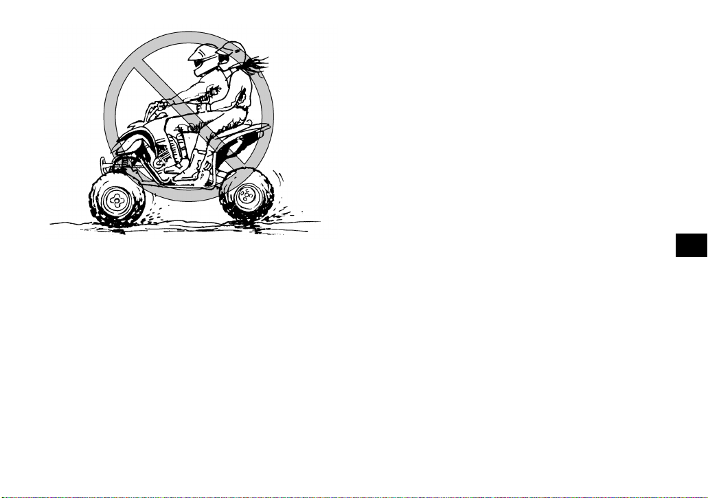
This ATV is designed to carry the operator only
– passengers prohibited.
The long seat is to allow the operator to shift position as needed during operation. It is not for carrying passengers. WARNING! Never carry a
passenger. Carrying a passenger on this ATV
greatly reduces your ability to balance and
control this ATV. You could have an accident,
resulting in severe injury or death to you
and/or your passenger.
[EWB01401]
7-3
Page 67
proved motorcycle helmet increases your
chances of a severe head injury or death in the
event of an accident.
[EWB01411]
Wear eye protection when operating your ATV to
reduce the risk of a serious accident or injury. Eye
protection, such as a face shield or goggles, may
reduce the risk of foreign material getting in your
eyes and help prevent loss of vision. WARNING!
Operating without eye protection can result in
an accident and increases your chances of a
severe injury in the event of an accident.
[EWB02611]
Apparel
Always wear the following to reduce risk of injury in
an accident:
● Approved motorcycle helmet that fits properly
● Eye protection (goggles, helmet face shield, or
protective eyewear)
● Over-the-ankle boots, gloves, long-sleeved shirt
or jacket, and long pants
An approved helmet and other personal protective
equipment can reduce the severity of injuries in an
accident. WARNING! Operating without an ap-
7
7-4
Page 68

1. Protective clothing
2. Goggles
3. Gloves
4. Boots
7
5. Helmet
Do not operate after or while consuming alcohol or drugs.
The operator’s performance capability is reduced
by the influence of alcohol or drugs. Consuming alcohol or drugs could seriously affect your judgment, cause you to react more slowly, and affect
your balance and perception. WARNING! Never
consume alcohol or drugs before or while driving this ATV. You increase your chance of an
accident.
[EWB01421]
Pre-operation checks
Always inspect your ATV each time you use it to
make sure the ATV is in safe operating condition.
Perform the pre-operation checks listed on page
5-1. Always follow the inspection and maintenance
procedures and schedules described in the Owner’s Manual. WARNING! Failure to inspect the
ATV before operating it and to maintain it properly increases the possibility of an accident or
equipment damage.
[EWB01431]
Speed limiter
For riders less experienced with this model, the
throttle lever housing is equipped with a speed limiter. The speed limiter keeps the throttle from fully
7-5
Page 69
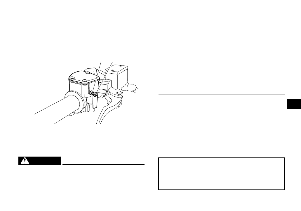
opening, even when the throttle lever is pushed to
the maximum. Turning in the adjusting screw limits
the maximum engine power available and decreases the maximum speed of the ATV. Turning
in the adjusting screw decreases top speed, and
turning it out increases top speed. (See page 4-4.)
2
1
● Do not exceed the maximum loading limits
for the vehicle (see box in this section or vehicle labeling).
● Make sure the load does not interfere with
your control or ability to see where you are
going.
● Reduce speed and allow more room to stop.
A heavier vehicle takes longer to stop.
● Avoid hills and rough terrain. Choose terrain
carefully. Use extreme caution when towing
or carrying a load on inclines.
● Turn gradually and go slowly.
1. Adjusting screw
2. Locknut
Loading and accessories
EWB00971
WARNING
Improper loading or towing can increase the
risk of loss of control, an overturn, or other accident. To reduce the risk of an accident:
As originally equipped, this ATV is not designed to
carry cargo or tow a trailer. If you choose to add accessories to carry cargo, you must use common
sense and good judgment.
Use extra caution when riding the ATV with additional loads, such as accessories or cargo. The
ATV’s handling may be adversely affected. Reduce your speed when adding additional loads.
MAXIMUM LOADING LIMIT
ATV loading limit (total weight of cargo, rider,
accessories, and tongue):
100.0 kg (220 lb)
7-6
7
Page 70

During operation
Always keep your feet on the footrests during operation; otherwise, they may contact the rear
wheels. WARNING! Removing even one hand
or foot can reduce your ability to control the
ATV or could cause you to lose your balance
and fall off of the ATV. If you remove a foot
from a footrest, your foot or leg may come into
contact with the rear wheels, which could injure you or cause an accident.
[EWB02660]
7
Avoid wheelies and jumping. WARNING! Attempting wheelies, jumps, and other stunts increases the chance of an accident, including
an overturn. Never attempt stunts, such as
wheelies or jumps. Don’t try to show off.
[EWB01481]
Modifications and accessories
Never modify this ATV through improper installation or use of accessories or other modification. All
parts and accessories added to this ATV should be
genuine Yamaha or equivalent components designed for use on this ATV and should be installed
and used according to instructions. If you have
7-7
Page 71

questions, consult an authorized ATV dealer.
WARNING! Operating this ATV with improper
modifications may cause changes in handling
which in some situations could lead to an accident.
[EWB01491]
Exhaust system
EWB01501
WARNING
● Dry grass or brush or other combustible ma-
terial accumulated around the engine area
could catch fire. Do not operate, idle, or park
the ATV in dry grass or other dry ground cov-
er. Keep the engine area free of dry grass,
brush, or other combustible material.
● Someone touching the exhaust system dur-
ing or after operation could be burned. Do
not touch the hot exhaust system. Do not
park the ATV in a place where others might
be likely to touch it.
The muffler and other engine parts become extremely hot during operation and remain hot after
the engine has stopped. To reduce the risk of fire
during operation or after leaving the ATV, do not let
brush, grass and other materials collect under the
vehicle, near the muffler or exhaust pipe, or next to
other hot parts. Check under the vehicle after operating in areas where combustible materials may
have collected. Do not idle or park the vehicle in
long dry grass or other dry ground cover.
To prevent burns, avoid touching the exhaust system. Park the ATV in a place where pedestrians or
children are not likely to touch it.
7
7-8
Page 72
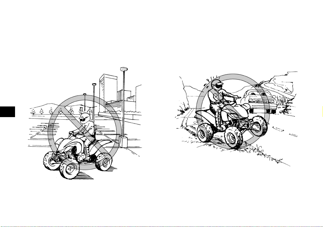
BE CAREFUL WHERE YOU RIDE
This ATV is designed for use on unpaved surfaces
only. WARNING! Paved surfaces may seriously
affect handling and control of the ATV, and
may cause the ATV to go out of control. Always
avoid paved surfaces, including sidewalks,
driveways, parking lots and streets.
[EWB01511]
7
While riding on unpaved public streets or roads
may be legal in your area, such operation can increase the risk of collision with other vehicles.
Watch carefully for other vehicles. Make sure you
know your country’s laws and regulations before
you ride on unpaved public streets or roads. Do not
ride on any paved public street, road or motorway.
WARNING! Never operate this ATV on any
paved street, paved road or motorway. You can
collide with another vehicle.
[EWB01521]
Know the terrain where you ride. Ride cautiously in
unfamiliar areas. Stay alert for holes, rocks, or
roots in the terrain, and other hidden hazards
which may cause the ATV to upset. WARNING!
The ATV could go out of control if you do not
7-9
Page 73

have enough time to react to hidden rocks,
bumps, or holes. Go slowly and be extra careful when operating on unfamiliar terrain. Always be alert to changing terrain conditions
when operating the ATV.
[EWB01531]
Do not operate on rough, slippery, or loose terrain
until you have learned and practiced the skills necessary to control the ATV on such terrain. Always
be especially cautious on these kinds of terrain.
WARNING! Failure to use extra care when operating on excessively rough, slippery, or
loose terrain could cause loss of traction or
ATV control, which could result in an accident,
including an overturn.
[EWB01541]
When riding in an area where you might not easily
be seen, such as desert terrain, mount a caution
flag on the ATV. DO NOT use the flag pole bracket
as a trailer hitch. WARNING! You could collide
with another vehicle if operating in areas where
you cannot easily be seen. Mount a caution
flag on the ATV to make you more visible.
Watch carefully for other vehicles.
[EWB01551]
7
7-10
Page 74

7 Do not ride in areas posted “no trespassing”.
Do not ride on private property without getting permission.
Select a large, flat, unpaved area to become familiar with your ATV. Make sure that this area is free
of obstacles and other riders. You should practice
control of the throttle, brakes, shifting procedures,
and turning techniques in this area before trying
more difficult terrain.
Set the parking brake and follow the instruction on
page 6-1 to start the engine. Once it has warmed
up you are ready to begin riding your ATV. As you
get on the ATV, be sure not to accidentally move
the shift pedal. With the engine idling, pull the
clutch lever to disengage the clutch and shift into
1st gear, and then release the parking brake. Open
the throttle gradually, and at the same time, release the clutch lever slowly. Once the ATV has attained adequate speed, release the throttle lever
and at the same time, quickly pull in the clutch lever and shift into 2nd gear. Open the throttle part
way and gradually release the clutch. WARNING!
If the throttle is applied too abruptly or if the
throttle is not released during shifting, or if the
shift pedal is not released before applying the
throttle, the front wheels may lift off the
ground, resulting in a loss of directional con-
7-11
Page 75

trol.
[EWB02631] NOTICE: Do not shift gears without
releasing the throttle. Damage to the engine or
drive train may occur.
[ECB01071]
Use this same procedure as you move into the
higher gears. Be sure to coordinate the use of the
throttle and shift pedal properly.
Avoid higher speeds until you are thoroughly familiar with the operation of your ATV.
When slowing down or stopping, release the throttle and apply the brakes smoothly and evenly. As
you slow down, shift to a lower gear. Be sure that
the engine has sufficiently slowed before engaging
a lower gear. Improper use of the brakes or shifting
can cause the tires to lose traction, reducing control and increasing the possibility of an accident.
TURNING YOUR ATV
EWB01771
WARNING
Always follow proper procedures for turning
as described in this Owner’s Manual. Practice
turning at low speeds before attempting to turn
at faster speeds. Do not turn at speeds too fast
for your skills or the conditions. ATV could go
out of control, causing a collision or overturn.
To achieve maximum traction on unpaved surfaces, the two rear wheels turn together at the same
speed. Therefore, unless the wheel on the inside
of the turn is allowed to slip or lose some traction,
the ATV will resist turning. A special turning technique must be used to allow the ATV to make turns
quickly and easily. It is essential that this skill be
learned first at low speed.
As you approach a curve, slow down and begin to
turn the handlebars in the desired direction. As you
do so, put your weight on the footrest to the outside
of the turn (opposite your desired direction) and
lean your upper body into the turn. Use the throttle
to maintain an even speed through the turn. This
maneuver will let the wheel on the inside of the turn
slip slightly, allowing the ATV to make the turn
properly.
7
7-12
Page 76

1
2
1. Lean towards inside of turn.
7
2. Support your weight on the outer footrest.
This procedure should be practiced at slow speed
many times in a large unpaved area with no obstacles. If an incorrect technique is used, your ATV
may continue to go straight. If the ATV doesn’t
turn, come to a stop and then practice the procedure again. If the riding surface is slippery or loose,
it may help to position more of your weight over the
front wheels by moving forward on the seat.
Once you have learned this technique, you should
be able to perform it at higher speeds or in tighter
curves.
Improper riding procedures such as abrupt throttle
changes, excessive braking, incorrect body movements, or too much speed for the sharpness of the
turn may cause the ATV to tip. If the ATV begins to
tip over to the outside while negotiating a turn, lean
more to the inside. It may also be necessary to
gradually let off on the throttle and steer to the outside of the turn to avoid tipping over.
Remember: Avoid higher speeds until you are
thoroughly familiar with the operation of your ATV.
CLIMBING UPHILL
EWB01591
WARNING
Climbing hills improperly can cause overturns
or loss of control. Use proper riding techniques described in this Owner’s Manual.
● Never operate the ATV on hills too steep for
the ATV or for your abilities. The ATV can
overturn more easily on extremely steep hills
than on level surfaces or small hills.
● Always check the terrain carefully before
you start up any hill. Never climb hills with
excessively slippery or loose surfaces.
● Shift your weight forward.
7-13
Page 77

● Never open the throttle suddenly or make
sudden gear changes. The ATV could flip
over backwards.
● Never go over the top of any hill at high
speed. An obstacle, a sharp drop, or another
vehicle or person could be on the other side
of the hill.
● Never attempt to turn the ATV around on any
hill until you have mastered the turning tech-
nique as described in the Owner’s Manual on
level ground. Be very careful when turning
on any hill.
● Avoid crossing the side of a steep hill if pos-
sible. When crossing the side of a hill, shift
your weight to the uphill side of the ATV.
7
7-14
Page 78

7
Do not attempt to climb hills until you have mastered basic maneuvers on flat ground. Always
check the terrain carefully before attempting any
hill. In all cases avoid inclines with slippery or loose
surfaces, or obstacles that might cause you to lose
control.
To climb a hill, you need traction, momentum, and
steady throttle. Travel fast enough to maintain momentum, but not so fast that you cannot react to
changes in the terrain as you climb.
It is important when climbing a hill to make sure
that your weight is transferred forward on the ATV.
This can be accomplished by leaning forward and,
on steeper inclines, standing on the footrests and
leaning forward over the handlebars. Whenever
possible, ride straight up hills.
Slow down when you reach the crest of the hill if
you cannot see clearly what is on the other side –
there could be another person, an obstacle, or a
sharp drop-off. Use common sense and remember
that some hills are too steep for you to climb or descend.
If you are climbing a hill and you find that you have
not properly judged your ability to make it to the
top, you should turn the ATV around while you still
have forward motion (provided you have the room
to do so) and go down the hill.
If your ATV has stalled or stopped and you believe
you can continue up the hill, restart carefully to
make sure you do not lift the front wheels which
could cause you to lose control. If you are unable
to continue up the hill, dismount the ATV on the uphill side. Physically turn the ATV around and then
descend the hill.
7-15
Page 79

If you start to roll backwards, DO NOT apply the
rear brake, and apply the front brake gradually.
The ATV could easily tip over backwards. When
fully stopped, apply the rear brake as well, and
then lock the parking brake. Dismount the ATV immediately on the uphill side or to a side if pointed
straight uphill. Turn the ATV around and remount,
following the procedure described in the Owner’s
Manual. WARNING! Stalling, rolling backwards
or improperly dismounting while climbing a hill
could result in ATV overturning. If you cannot
control the ATV, dismount immediately on the
uphill side.
[EWB01802]
7
RIDING DOWNHILL
EWB01131
WARNING
Going down a hill improperly could cause
overturns or loss of control. Always follow
proper procedures for going down hills as described in this Owner’s Manual.
● Always check the terrain carefully before
you start down any hill.
7-16
Page 80
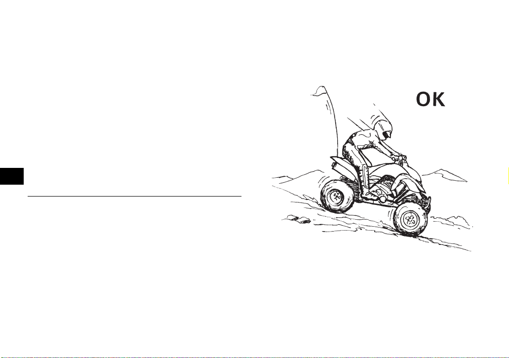
● Never operate the ATV on hills too steep for
the ATV or for your abilities. The ATV can
overturn more easily on extremely steep hills
than on level surfaces or small hills.
● Shift your weight backward and to the up
side of the hill.
● Never go down a hill at high speed.
● Avoid going down a hill at an angle that
would cause the ATV to lean sharply to one
side. Go straight down the hill where possible.
● Improper braking can cause the wheels on
the uphill side to come off the ground or
cause loss of traction. Gradually apply only
7
the rear brake when going downhill.
When riding your ATV downhill, shift your weight
as far to the rear and uphill side of the ATV as possible. Move back on the seat and sit with your arms
straight. Choose a low gear which will allow the engine compression to do most of the braking for you.
Use caution while descending a hill with loose or
slippery surfaces. Braking ability and traction may
be adversely affected by these surfaces. Improper
braking may also cause a loss of traction. Gradually apply only the rear brake.
Whenever possible, ride your ATV straight downhill. Avoid sharp angles which could allow the ATV
to tip or roll over. Carefully choose your path and
ride no faster than you will be able to react to obstacles which may appear.
7-17
Page 81
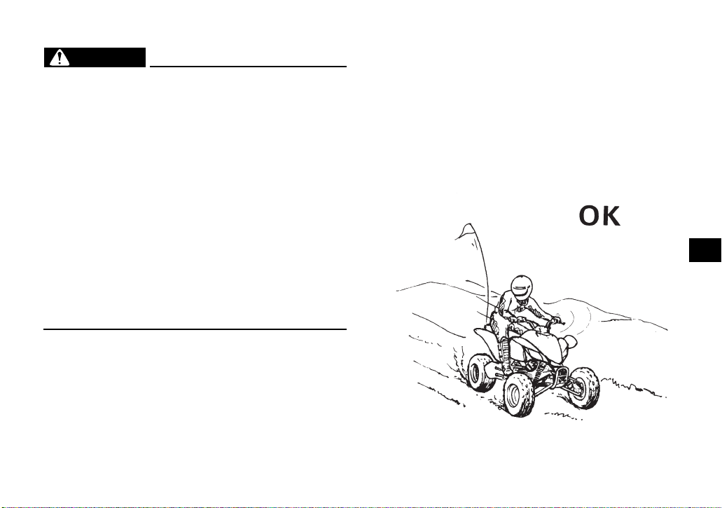
CROSSING A SLOPE
EWB01632
WARNING
Improperly crossing hills or turning on hills
could cause loss of control or cause the ATV to
overturn.
● Always follow proper procedures as de-
scribed in the Owner’s Manual.
● Avoid hills with excessively slippery or loose
surfaces.
● Avoid crossing the side of a steep hill.
● Shift your weight to the uphill side of the
ATV.
● Never attempt to turn the ATV around on any
hill until you have mastered the turning tech-
nique as described in the Owner’s Manual on
level ground. Be very careful when turning
on any hill.
Traversing a sloping surface on your ATV requires
you to properly position your weight to maintain
proper balance. Be sure that you have learned the
basic riding skills on flat ground before attempting
to cross a sloping surface. Avoid slopes with slippery surfaces or rough terrain that may upset your
balance.
As you travel across a slope, lean your body in the
uphill direction. It may be necessary to correct the
steering when riding on loose surfaces by pointing
the front wheels slightly uphill. When riding on
slopes, be sure not to make sharp turns either up
or down hill.
If your ATV does begin to tip over, gradually steer
in the downhill direction if there are no obstacles in
your path. As you regain proper balance, gradually
steer again in the direction you wish to travel.
7
7-18
Page 82
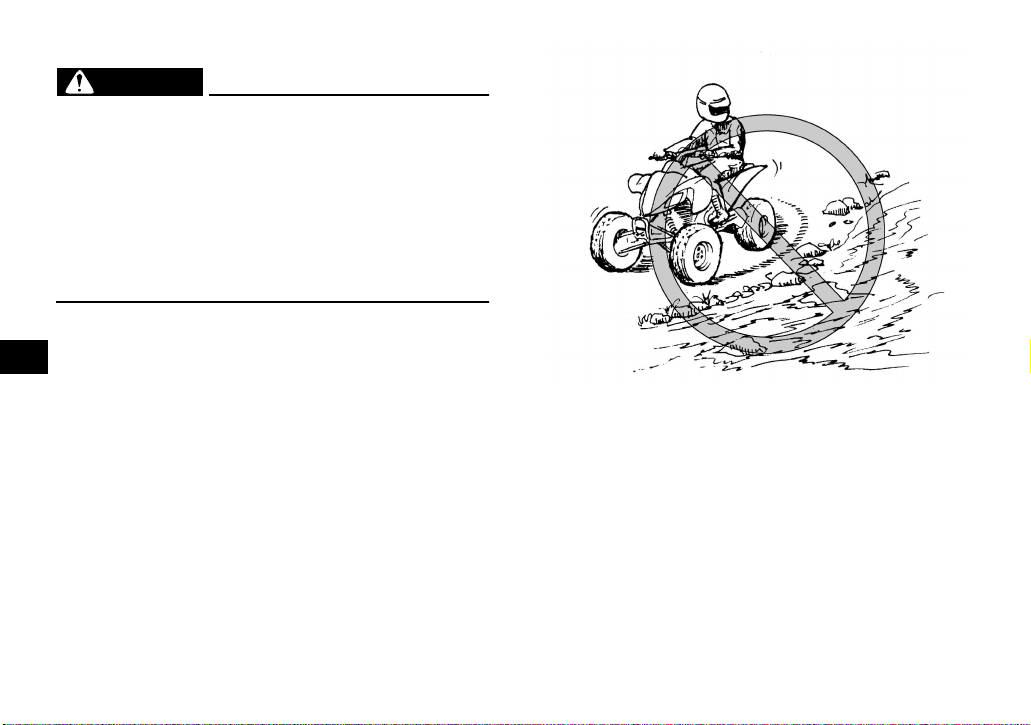
CROSSING THROUGH SHALLOW WATER
EWB01641
WARNING
Operating this vehicle through deep or fastflowing water can lead to loss of control or an
overturn. To reduce your risk of drowning or
other injuries, use care when crossing through
water. Never operate this ATV water deeper
than the depth specified in your Owner’s Manual, as tires may float, increasing the risk of an
overturn.
The ATV can be used to cross slow moving, shallow water of up to a maximum of 35 cm (14 in) in
7
depth. Before entering the water, choose your path
carefully. Enter where there is no sharp drop off,
and avoid rocks or other obstacles which may be
slippery or upset the ATV. Drive slowly and carefully.
Test your brakes after leaving the water. If necessary, apply them several times to let friction dry out
the linings. Do not continue to ride your ATV without verifying that you have regained proper braking
ability. WARNING! Wet brakes may have re-
duced stopping ability, which could cause loss
of control.
[EWB02621]
7-19
Page 83

1. Air filter case check hose
1
After riding your ATV in water, be sure to drain the
trapped water by removing the check hose at the
bottom of the air filter case. NOTICE: Undrained
water can cause damage or improper operation.
[ECB00841]
Wash the ATV in fresh water if it has been operated in salt water or muddy conditions.
RIDING OVER ROUGH TERRAIN
EWB01651
WARNING
Riding improperly over obstacles could cause
loss of control or a collision. Before operating
in a new area, check for obstacles. Never attempt to ride over large obstacles, such as
large rocks or fallen trees. When you go over
obstacles, always follow proper procedures as
described in the Owner’s Manual.
Riding over rough terrain should be done with caution. Look out for obstacles which could cause
damage to the ATV or could lead to an upset or ac-
7-20
7
Page 84

cident. Be sure to keep your feet firmly mounted on
the footrests at all times. Avoid jumping the ATV as
loss of control and damage to the ATV may result.
SLIDING AND SKIDDING
EWB01662
WARNING
Skidding or sliding improperly may cause you
to lose control of this ATV. You may also regain traction unexpectedly, which may cause
the ATV to overturn.
● Learn to safely control skidding or sliding by
practicing at low speeds and on level,
smooth terrain.
7
● On extremely slippery surfaces, such as ice,
go slowly and be very cautious in order to reduce the chance of skidding or sliding out of
control.
Care should be used when riding on loose or slippery surfaces since the ATV may slide. If unexpected and uncorrected, sliding could lead to an
accident.
To reduce the tendency for the front wheels to slide
in loose or slippery conditions, positioning your
weight over the front wheels will sometimes help.
If the rear wheels of your ATV start to slide sideways, control can usually be regained (if there is
room to do so) by steering in the direction of the
slide. Applying the brakes or accelerating is not
recommended until you have corrected the slide.
7-21
Page 85

With practice, over a period of time, skill at controlled sliding can be developed. The terrain
should be chosen carefully before attempting such
maneuvers, since both stability and control are reduced. Bear in mind that sliding maneuvers should
always be avoided on extremely slippery surfaces
such as ice, since all control may be lost.
WHAT TO DO IF...
This section is designed to be a reference guide
only. Be sure to read each section on riding techniques completely.
WHAT TO DO...
● If your ATV doesn’t turn when you want it to:
Bring the ATV to a stop and practice the turning
maneuvers again. Be sure you are putting your
weight on the footrest to the outside of the turn.
Position your weight over the front wheels for
better control. (See page 7-12.)
● If your ATV begins to tip while turning:
Lean more into the turn to regain balance. If necessary, gradually let off the throttle and/or steer
to the outside of the turn. (See page 7-12.)
● If your ATV starts to slide sideways:
Steer in the direction of the slide if you have the
room. Applying the brakes or accelerating is not
recommended until you have corrected the
slide. (See page 7-21.)
● If your ATV can’t make it up a hill you are trying
to climb:
Turn the ATV around if you still have forward
speed. If not, stop, dismount on the uphill side of
the ATV and physically turn the ATV around. If
the ATV starts to slip backwards, DO NOT USE
THE REAR BRAKE – the ATV may tip over on
top of you. Dismount the ATV on the uphill side.
(See page 7-13.)
7
7-22
Page 86

● If your ATV is traversing a sloping surface:
Be sure to ride with your weight positioned towards the uphill side of the ATV to maintain
proper balance. If the ATV starts to tip, steer
down the hill (if there are no obstacles in your
way) to regain balance. If you discover that the
ATV is going to tip over, dismount on the uphill
side. (See page 7-18.)
● If your ATV encounters shallow water:
Ride slowly and carefully through slow moving
water, watching for obstacles. Be sure to let water drain from the ATV and CHECK YOUR
BRAKES FOR PROPER OPERATION when
you come out of the water. Do not continue to
7
ride your ATV until you have regained adequate
braking ability. (See page 7-19.)
7-23
Page 87

EBU28783
PERIODIC MAINTENANCE AND ADJUSTMENT
EBU21672
Periodic inspection, adjustment, and lubrication
will keep your vehicle in the safest and most efficient condition possible. Safety is an obligation of
the vehicle owner/operator. The most important
points of vehicle inspection, adjustment, and lubrication are explained on the following pages.
EWB01841
WARNING
Failure to properly maintain the vehicle or performing maintenance activities incorrectly may
increase your risk of injury or death during service or while using the vehicle. If you are not familiar with vehicle service, have a Yamaha
dealer perform the service.
EWB02561
WARNING
Turn off the engine when performing maintenance unless otherwise specified.
● A running engine has moving parts that can
catch on body parts or clothing and electri-
cal parts that can cause shocks or fires.
● Running the engine while servicing can lead
to eye injury, burns, fire, or carbon monoxide
poisoning - possibly leading to death. See
page 2-1 for more information about carbon
monoxide.
EWB02690
WARNING
Brake discs, calipers, drums, and linings can
become very hot during use. To avoid possible
burns, let brake components cool before
touching them.
The intervals given in the periodic maintenance
and lubrication chart should be considered as a
general guide under normal riding conditions.
However, DEPENDING ON THE WEATHER,
TERRAIN, GEOGRAPHICAL LOCATION, AND
INDIVIDUAL USE, THE MAINTENANCE INTERVALS MAY NEED TO BE SHORTENED.
8
8-1
Page 88

EBU29790
Owner’s manual and tool kit
Be sure to put this owner’s manual in the cover and
always carry it along with the low-pressure tire
gauge and the owner’s tool kit under the seat.
4
3
2
1
TIP
If you do not have the tools or experience required
for a particular job, have a Yamaha dealer perform
it for you.
8
1. Low-pressure tire gauge
2. Owner’s tool kit
3. Owner’s manual
4. Manual cover
43
The service information included in this manual
and the tools provided in the owner’s tool kit are intended to assist you in the performance of preventive maintenance and minor repairs. However,
additional tools such as a torque wrench may be
necessary to perform certain maintenance work
correctly.
8-2
Page 89

EBU21743
Periodic maintenance chart for the emission control system
TIP
● For ATVs not equipped with an odometer or an hour meter, follow the month maintenance intervals.
● For ATVs equipped with an odometer or an hour meter, follow the km (mi) or hours maintenance inter-
vals. However, keep in mind that if the ATV isn’t used for a long period of time, the month maintenance
intervals should be followed.
● Items marked with an asterisk should be performed by a Yamaha dealer as they require special tools,
data and technical skills.
INITIAL EVERY
NO. ITEM
1 * Fuel line
2 Spark plug
3 * Valves • Check valve clearance and adjust if necessary. √ √√√
4 * Carburetor
Crankcase breather
5 *
system
CHECK OR MAINTENANCE
JOB
• Check fuel hoses for cracks or other damage, and
replace if necessary.
• Check condition and clean, regap, or replace if
necessary.
• Check starter (choke) operation and correct if necessary.
• Check engine idling speed and adjust if necessary.
• Check breather hose for cracks or other damage,
and replace if necessary.
Whichever comes
first
month136612
km
(mi)
hours 20 80 160 160 320
320
(200)
1300
(800)
√√√√√
2500
(1600)
√√√√
2500
(1600)
√√√
√√√
5000
(3200)
8
8-3
Page 90

INITIAL EVERY
NO. ITEM
6 * Exhaust system
7 Spark arrester • Clean. √√√
CHECK OR MAINTENANCE
JOB
• Check for leakage and replace gasket(s) if necessary.
• Check for looseness and tighten all screw clamps
and joints if necessary.
Whichever comes
first
month136612
km
320
(mi)
(200)
hours 20 80 160 160 320
1300
(800)
2500
(1600)
2500
(1600)
√√√
8
5000
(3200)
8-4
Page 91

EBU21865
General maintenance and lubrication chart
TIP
● For ATVs not equipped with an odometer or an hour meter, follow the month maintenance intervals.
● For ATVs equipped with an odometer or an hour meter, follow the km (mi) or hours maintenance inter-
vals. However, keep in mind that if the ATV isn’t used for a long period of time, the month maintenance
intervals should be followed.
● Items marked with an asterisk should be performed by a Yamaha dealer as they require special tools,
data and technical skills.
INITIAL EVERY
NO. ITEM
1 Air filter element • Clean and replace if necessary.
2 * Clutch • Check operation and adjust if necessary. √ √√√
3 * Front brake
4 * Rear brake
CHECK OR MAINTENANCE
JOB
• Check operation and correct if necessary.
• Check fluid level and ATV for fluid leakage, and
correct if necessary.
• Replace brake pads. Whenever worn to the limit
• Check operation and correct if necessary.
• Check fluid level and ATV for fluid leakage, and
correct if necessary.
• Replace brake pads. Whenever worn to the limit
Whichever comes
first
8-5
month136612
km
(mi)
hours 20 80 160 160 320
320
(200)
Every 20–40 hours (more often in wet or
1300
(800)
√√√√√
√√√√√
2500
(1600)
dusty areas)
2500
(1600)
5000
(3200)
8
Page 92

INITIAL EVERY
NO. ITEM
5 * Brake hoses
6 * Parking brake • Check operation and adjust if necessary. √√√√√
7 * Wheels
8 * Tires
8
9 * Wheel hub bearings
10 * Swingarm pivots
11 *
12 Drive chain
13 * Drive chain roller • Check for wear and replace if necessary. √√√
Upper and lower
arm pivots
CHECK OR MAINTENANCE
JOB
• Check for cracks or other damage, and replace if
necessary.
• Replace. Every 4 years
• Check runout and for damage, and replace if nec-
essary.
• Check tread depth and for damage, and replace if
necessary.
• Check air pressure and balance, and correct if
necessary.
• Check for looseness or damage, and replace if
necessary.
• Check operation and for excessive play, and replace bearings if necessary.
• Lubricate with lithium-soap-based grease.
• Lubricate with lithium-soap-based grease. √√√
• Check chain slack and adjust if necessary.
• Check rear wheel alignment and correct if neces-
sary.
• Clean and lubricate.
Whichever comes
first
8-6
month136612
km
320
(mi)
(200)
hours 20 80 160 160 320
1300
(800)
√ √√√
√ √√√
√ √√√
√√√√√
2500
(1600)
√√√√
2500
(1600)
√√√
5000
(3200)
Page 93

INITIAL EVERY
NO. ITEM
14 * Chassis fasteners
Shock absorber as-
15 *
semblies
16 * Steering shaft • Lubricate with lithium-soap-based grease. √√√
17 * Steering system
18 Engine oil
Engine oil filter ele-
19
ment
Moving parts and
20 *
cables
Throttle lever hous-
21 *
ing and cable
Front and rear brake
22 *
switches
23 * Lights and switches
CHECK OR MAINTENANCE
JOB
• Make sure that all nuts, bolts, and screws are
properly tightened.
• Check operation and correct if necessary.
• Check for oil leakage and replace if necessary.
• Check operation and repair or replace if damaged.
• Check toe-in and adjust if necessary.
• Change.
• Check ATV for oil leakage, and correct if neces-
sary.
• Replace. √√√
• Lubricate. √√√√
• Check operation and correct if necessary.
• Check throttle cable free play and adjust if neces-
sary.
• Lubricate throttle lever housing and cable.
• Check operation and correct if necessary. √√√√√
• Check operation and correct if necessary.
• Adjust headlight beams.
Whichever comes
first
8-7
month136612
km
(mi)
hours 20 80 160 160 320
320
(200)
1300
(800)
√√√√√
√√√√√
√ √√√
√√√√√
√√√√√
2500
(1600)
2500
(1600)
√√√
5000
(3200)
8
Page 94

EBU23071
TIP
● Some maintenance items need more frequent service if you are riding in unusually wet, dusty, sandy or
muddy areas, or at full-throttle.
● Hydraulic brake service
• Regularly check and, if necessary, correct the brake fluid level.
• Every two years replace the internal components of the brake master cylinders and calipers, and
change the brake fluid.
• Replace the brake hoses every four years and if cracked or damaged.
8
8-8
Page 95

EBU23213
Checking the spark plug
The spark plug is an important engine component,
which is easy to check. Since heat and deposits
will cause any spark plug to slowly erode, the spark
plug should be removed and checked in accordance with the periodic maintenance and lubrication chart. In addition, the condition of the spark
plug can reveal the condition of the engine.
To remove the spark plug
1. Remove the spark plug cap.
1
1. Spark plug cap
2. Remove the spark plug as shown, with the
spark plug wrench included in the owner’s tool
kit.
1
1. Spark plug wrench
To check the spark plug
1. Check that the porcelain insulator around the
center electrode of the spark plug is a medium-to-light tan (the ideal color when the ATV
is ridden normally).
TIP
If the spark plug shows a distinctly different color,
the engine could be operating improperly. Do not
attempt to diagnose such problems yourself. Instead, have a Yamaha dealer check the ATV.
8
8-9
Page 96

2. Check the spark plug for electrode erosion
and excessive carbon or other deposits, and
replace it if necessary.
Specified spark plug:
NGK/DR7EA
3. Measure the spark plug gap with a wire thickness gauge and, if necessary, adjust the gap
to specification.
8
1. Spark plug gap
Spark plug gap:
0.6–0.7 mm (0.024–0.028 in)
To install the spark plug
1. Clean the surface of the spark plug gasket
and its mating surface, and then wipe off any
grime from the spark plug threads.
2. Install the spark plug with the spark plug
wrench, and then tighten it to the specified
torque.
Tightening torque:
Spark plug:
18 Nm (1.8 m·kgf, 13 ft·lbf)
TIP
If a torque wrench is not available when installing
the spark plug, a good estimate of the correct
torque is 1/4–1/2 turn past finger tight. However,
the spark plug should be tightened to the specified
torque as soon as possible.
3. Install the spark plug cap.
8-10
Page 97

EBU28957
Engine oil and oil filter element
The engine oil level should be checked before
each ride. In addition, the oil must be changed and
the oil filter element must be replaced at the intervals specified in the periodic maintenance and lubrication chart.
To check the engine oil level
1. Place the ATV on a level surface.
2. Check the engine oil level on a cold engine.
TIP
If the engine was started before checking the oil
level, be sure to warm up the engine sufficiently,
and then wait at least ten minutes until the oil settles for an accurate reading.
3. Remove the engine oil filler cap, and then
wipe the engine oil dipstick off with a clean
rag.
4. Insert the dipstick into the filler hole (without
screwing it in), and then remove it again to
check the oil level.
TIP
The engine oil should be between the minimum
and maximum level marks.
1
2
3
4
1. Engine oil filler cap
2. Engine oil dipstick
3. Maximum level mark
4. Minimum level mark
5. If the engine oil is at or below the minimum
level mark, add sufficient oil of the recommended type to raise it to the correct level.
NOTICE: Be sure the engine oil is at the
correct level, otherwise engine damage
may result.
[ECB00851]
8
8-11
Page 98

6. Insert the dipstick into the oil filler hole, and
then tighten the engine oil filler cap.
To change the engine oil (with or without oil filter element replacement)
1. Place the ATV on a level surface.
2. Start the engine, warm it up for several minutes, and then turn it off.
3. Place an oil pan under the engine to collect
the used oil.
4. Remove the engine oil filler cap, and then remove the engine oil drain bolt and its gasket to
drain the oil from the crankcase.
TIP
Skip steps 5–7 if the oil filter element is not being
replaced.
5. Remove the oil filter element cover by removing the bolts, and then remove the oil filter element and the O-rings.
2
8
1. Engine oil drain bolt
2. Gasket
1
2
1. Oil filter element cover
2. Bolt
1
8-12
Page 99
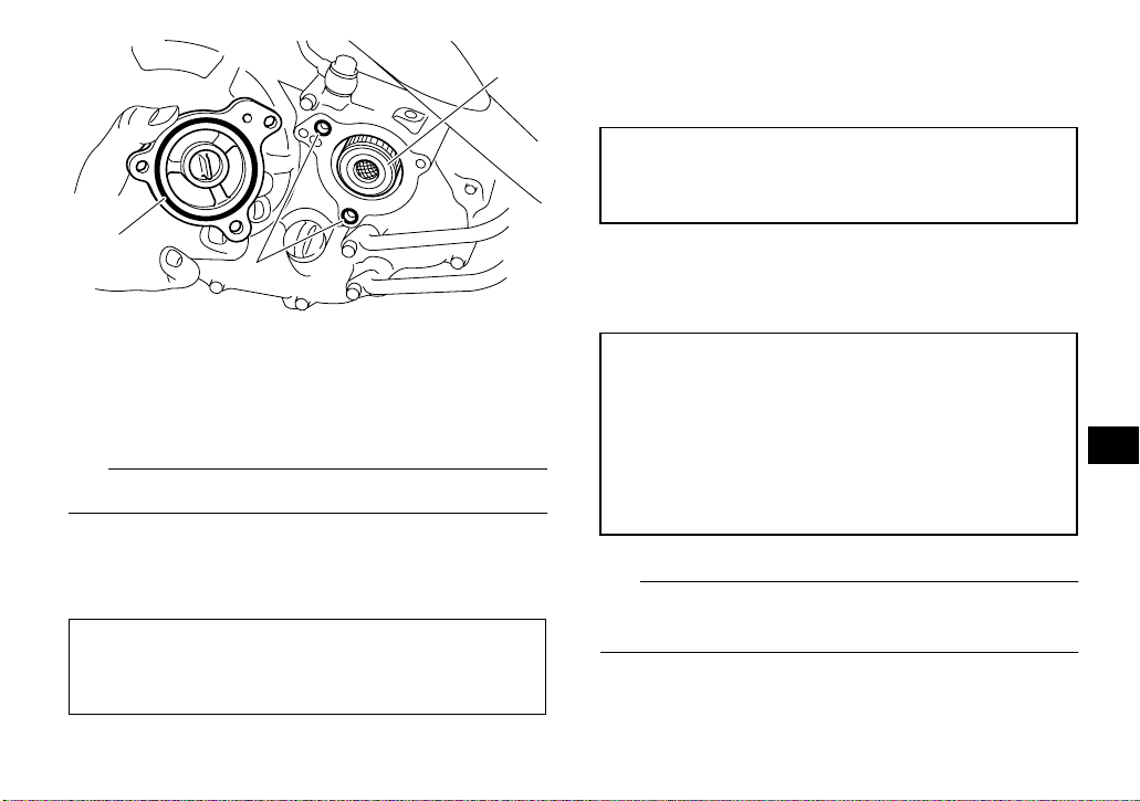
8. Install the engine oil drain bolt and its new
1
gasket, and then tighten the bolt to the specified torque.
Tightening torque:
Engine oil drain bolt:
20 Nm (2.0 m·kgf, 14 ft·lbf)
2
2
1. Oil filter element
2. O-ring
6. Install a new oil filter element and new Orings.
TIP
Make sure that the O-rings are properly seated.
7. Install the oil filter element cover by installing
the bolts, and then tighten them to the specified torque.
Tightening torque:
Oil filter element cover bolt:
10 Nm (1.0 m·kgf, 7.2 ft·lbf)
9. Refill with the specified amount of the recommended engine oil, and then install and tighten the engine oil filler cap.
Recommended oil:
See page 10-1.
Oil quantity:
Without oil filter element replacement:
1.25 L (1.32 US qt, 1.10 Imp.qt)
With oil filter element replacement:
1.35 L (1.43 US qt, 1.19 Imp.qt)
TIP
Be sure to wipe off spilled oil on any parts after the
engine and exhaust system have cooled down.
8-13
8
Page 100
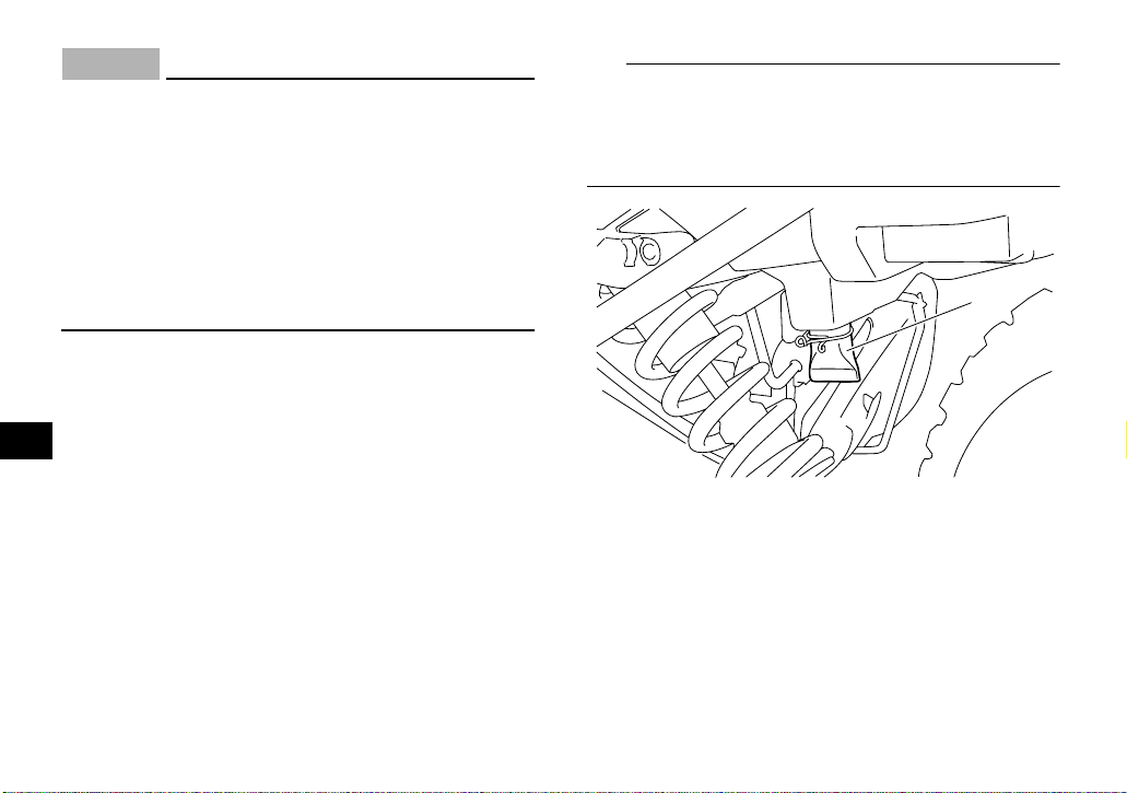
ECB00300
NOTICE
● In order to prevent clutch slippage (since the
engine oil also lubricates the clutch), do not
mix any chemical additives. Do not use oils
with a diesel specification of “CD” or oils of
a higher quality than specified. In addition,
do not use oils labeled “ENERGY CONSERVING II” or higher.
● Make sure that no foreign material enters the
crankcase.
10. Start the engine, and then let it idle for several
minutes while checking it for oil leakage. If oil
is leaking, immediately turn the engine off and
8
check for the cause.
11. Turn the engine off, wait at least ten minutes,
and then check the oil level and correct it if
necessary.
EBU23707
Cleaning the air filter element
The air filter element should be cleaned at the intervals specified in the periodic maintenance and
lubrication chart. Clean or, if necessary, replace
the air filter element more frequently if you are
riding in unusually wet or dusty areas.
TIP
There is a check hose at the bottom of the air filter
case. If dust or water collects in this hose, empty
the hose and clean the air filter element and air filter case.
1
1. Air filter case check hose
1. Place the ATV on a level surface.
2. Remove the seat. (See page 4-12.)
3. Remove the air filter case cover by unhooking
the holders.
8-14
 Loading...