


2002
YFM250X
SUPPLEMENTARY
(
P
4XE3-AE3
)
SERVICE MANUAL


FOREWORD
This Supplementary Service Manual has been prepared to introduce new service and new data for
the YFM250X(P) 2002. For complete information on service procedures, it is necessary to use this
Supplementary Service Manual together with the following manual.
YFM250XL’99 SERVICE MANUAL: 4XE3-AE1
YFM250XN 2001 SUPPLEMENTARY SERVICE MANUAL: 4XE3-AE2
YFM250X(P) 2002
SUPPLEMENTARY
SERVICE MANUAL
2001 by Yamaha Motor Co., Ltd.
First Edition, June 2001
All rights reserved.
Any reproduction or unauthorized use
without the written permission of
Yamaha Motor Co., Ltd.
is expressly prohibited.
EB001000
NOTICE
This manual was produced by the Yamaha Motor Company primarily for use by Yamaha dealers
and their qualified mechanics. It is not possible to include all the knowledge of a mechanic in one
manual, so it is assumed that anyone who uses this book to perform maintenance and repairs on
Yamaha machine has a basic understanding of the mechanical ideas and the procedures of
machine repair. Repairs attempted by anyone without this knowledge are likely to render the
machine unsafe and unfit for use.
Yamaha Motor Company, Ltd. is continually striving to improve all its models. Modifications and significant changes in specifications or procedures will be forwarded to all authorized Yamaha dealers
and will appear in future editions of this manual where applicable.
OTE:
Designs and specifications are subject to change without notice.
IMPORTANT INFORMATION
Particularly important information is distinguished in this manual by the following notations.
The Safety Alert Symbol means ATTENTION! BECOME ALERT! YOUR
SAFETY IS INVOLVED!
WARNING
CAUTION:
NOTE:
Failure to follow WARNING instructions could result in severe injury or death
to the machine operator, a bystander or a person inspecting or repairing the
machine.
A CAUTION indicates special precautions that must be taken to avoid damage to the machine.
A NOTE provides key information to make procedures easier or clearer.
HOW TO USE THIS MANUAL
CONSTRUCTION OF THIS MANUAL
This manual consists of chapters for the main categories of subjects. (See “Illustrated symbols”)
1st title 1: This is a chapter with its symbol on the upper right of each page.
2nd title 2: This title appears on the upper of each page on the left of the chapter sym-
bol. (For the chapter “Periodic inspection and adjustment” the 3rd title
appears.)
3rd title 3: This is a final title.
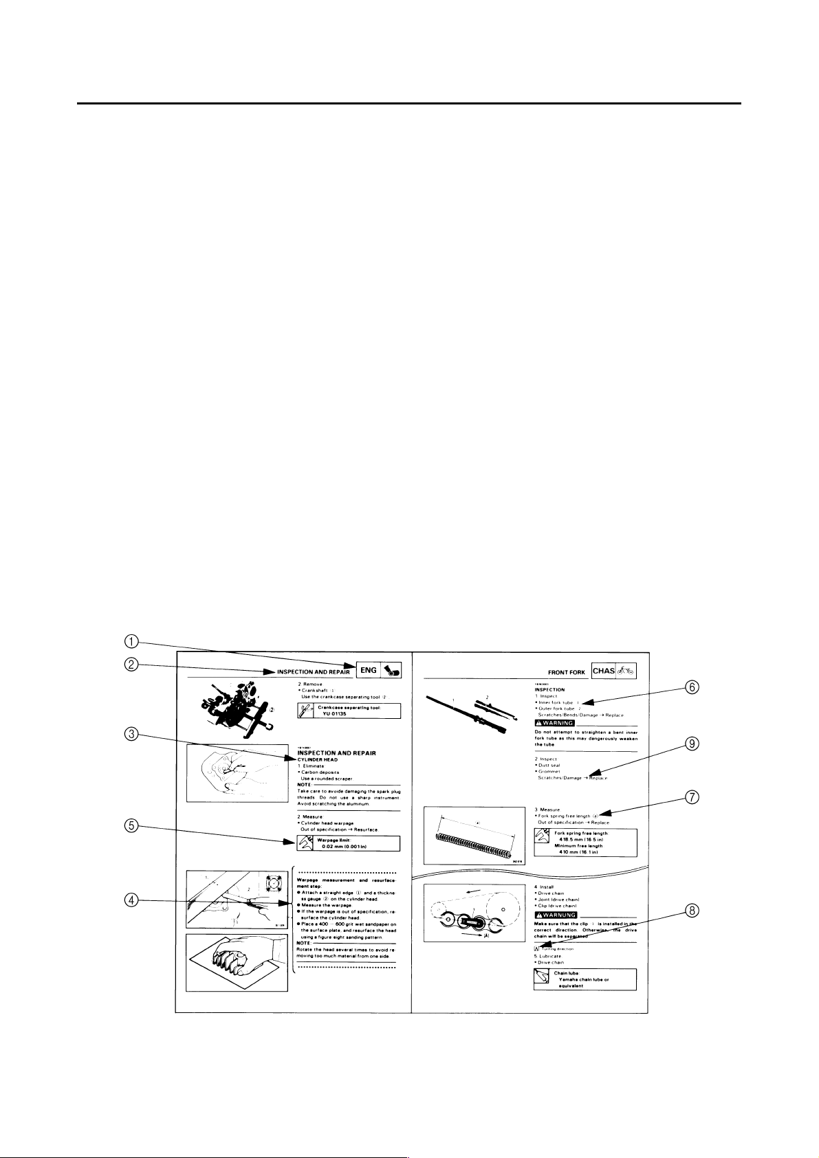
MANUAL FORMAT
All of the procedures in this manual are organized in a sequential, step-by-step format. The information has been compiled to provide the mechanic with an easy to read, handy reference that contains
comprehensive explanations of all disassembly, repair, assembly, and inspections.
A set of particularly important procedure 4 is placed between a line of asterisks “
dure preceded by “
●
”.
IMPORTANT FEATURES
●
Data and a special tool are framed in a box preceded by a relevant symbol 5.
●
An encircled numeral 6 indicates a part name, and an encircled alphabetical letter data or an
alignment mark 7, the others being indicated by an alphabetical letter in a box 8.
●
A condition of a faulty component will precede an arrow symbol 9 and the course of action will follow it.
*
” with each proce-
EXPLODED DIAGRAM
Each chapter provides exploded diagrams before each disassembly section for ease in identifying
correct disassembly and assembly procedures.
12
GEN
INFO
34
SPEC
CHK
ADJ
56
CARB
78
ENG
DRIV
EB003000
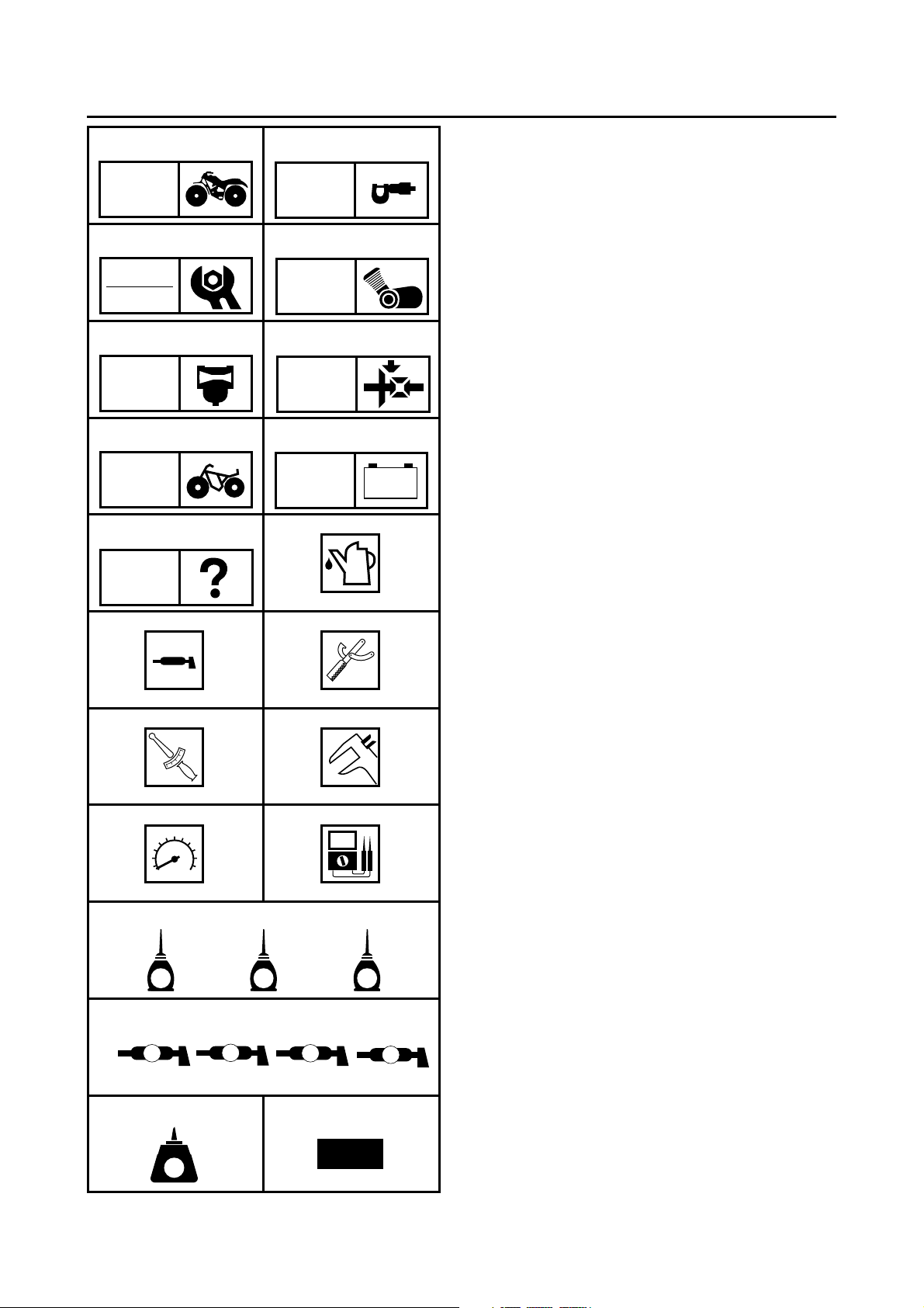
ILLUSTRATED SYMBOLS
Illustrated symbols 1 to 9 are printed on the
top right of each page and indicate the subject
of each chapter.
General information
1
Specifications
2
Periodic checks and adjustments
3
Engine
4
Carburetion
5
Drive train
6
Chassis
7
Electrical
8
Troubleshooting
9
CHAS
90
ELEC
– +
TRBL
SHTG
AB
CD
T
.
R
.
EF
GHI
Illustrated symbols 0 to F are used to identify
the specifications appearing in the text.
Filling fluid
0
Lubricant
A
Special tool
B
Torque
C
Wear limit, clearance
D
Engine speed
E
, V, A
Ω
F
Illustrated symbols G to M in the exploded
diagrams indicate the types of lubricants and
lubrication points.
LS
G
M
M
S
New
E
J
NO
KLM
B
LT
Apply engine oil
G
Apply gear oil
H
Apply molybdenum disulfide oil
I
Apply wheel bearing grease
J
Apply lightweight lithium soap base grease
K
Apply molybdenum disulfide grease
L
Apply silicon grease
M
Illustrated symbols N to O in the exploded
diagrams indicate where to apply a locking
agent N and when to install a new part O.
Apply the locking agent (LOCTITE
N
Replace
O
)

CONTENTS
SPECIFICATIONS
GENERAL SPECIFICATIONS ..................................................................1
MAINTENANCE SPECIFICATION ............................................................2
ENGINE ................................................................................................2
CHASSIS ..............................................................................................3
ELECTRICAL ........................................................................................3
CABLE ROUTING .....................................................................................4
PERIODIC CHECKS AND ADJUSTMENTS
INTRODUCTION .....................................................................................12
PERIODIC MAINTENANCE/LUBRICATION INTERVALS.......................12
CHASSIS .................................................................................................14
ADJUSTING THE FRONT BRAKE .....................................................14
ADJUSTING THE REAR BRAKE LIGHT SWITH ...............................14
ELECTRICAL
CHECKING THE SWITCH ......................................................................15
CHECKING THE SWITCH ..................................................................15
CHECKING A SWITCH SHOWN IN THE MANUAL ...........................15
SIGNAL SYSTEM ...................................................................................16
CIRCUIT DIAGRAM ............................................................................16
CHECKING THE SIGNAL SYSTEM ...................................................17
............................................................................................1
..................................................12
.................................................................................................15
YFM250X(P) 2002 WIRING DIAGRAM

GENERAL SPECIFICATIONS
SPEC
SPECIFICATIONS
GENERAL SPECIFICATIONS
Item Standard
Model code: 4XEF (CDN, Europe and Oceania)
Dimensions:
Overall length 1,940 mm (76.4 in)
Overall width 1,080 mm (42.5 in)
Overall height 1,118 mm (44.0 in)
Seat height 780 mm (30.7 in)
Wheelbase 1,170 mm (46.1 in)
Minimum ground clearance 150 mm (5.9 in)
Minimum turning radius 2,900 mm (114.2 in)
Brake:
Front brake type Dual disc brake
operation Right hand operation
Rear brake type Drum brake (fully sealed)
operation Left hand and right foot operation
Electrical:
Ignition system DC.C.D.I.
Generator system A.C. magneto
Battery type YB14A-A2
Battery capacity 12 V 14 AH
Bulb wattage × quantity:
Headlight 12 V 25 W/25 W × 2
Tail/brake light 12 V 5 W/21 W × 1
Indicator lights:
Neutral 12 V 1.7 W × 1
Reverse 12 V 1.7 W × 1
– 1 –
 Loading...