

Page 1
EN
FR
ES
EnglishFrançaisEspañol
STAGE KEYBOARD
CLAVIER DE SCÈNE
TECLADO DE ESCENARIO
Page 2

YC61 Owner’s Manual
2
Page 3

FCC INFORMATION (U.S.A.)
1. IMPORTANT NOTICE: DO NOT MODIFY THIS UNIT!
This product, when installed as indicated in the instructions
contained in this manual, meets FCC requirements. Modifications not expressly approved by Yamaha may void your
authority, granted by the FCC, to use the product.
2. IMPORTANT: When connecting this product to accessories
and/or another product use only high quality shielded cables.
Cable/s supplied with this product MUST be used. Follow all
installation instructions. Failure to follow instructions could
void your FCC authorization to use this product in the USA.
3. NOTE: This product has been tested and found to comply
with the requirements listed in FCC Regulations, Part 15 for
Class “B” digital devices. Compliance with these requirements provides a reasonable level of assurance that your
use of this product in a residential environment will not result
in harmful interference with other electronic devices. This
equipment generates/uses radio frequencies and, if not
installed and used according to the instructions found in the
users manual, may cause interference harmful to the operation of other electronic devices. Compliance with FCC regula-
* This applies only to products distributed by Yamaha Corporation of America. (class B)
COMPLIANCE INFORMATION STATEMENT (Supplierʼs declaration of conformity procedure)
Responsible Party: Yamaha Corporation of America
Address: 6600 Orangethorpe Ave., Buena Park, Calif. 90620
Telephone: 714-522-9011
Type of Equipment: STAGE KEYBOARD
Model Name: YC61
This device complies with Part 15 of the FCC Rules.
Operation is subject to the following two conditions:
1) this device may not cause harmful interference, and
2) this device must accept any interference received including interference that may cause undesired operation.
tions does not guarantee that interference will not occur in all
installations. If this product is found to be the source of interference, which can be determined by turning the unit “OFF”
and “ON”, please try to eliminate the problem by using one of
the following measures:
Relocate either this product or the device that is being
affected by the interference.
Utilize power outlets that are on different branch (circuit
breaker or fuse) circuits or install AC line filter/s.
In the case of radio or TV interference, relocate/reorient the
antenna. If the antenna lead-in is 300 ohm ribbon lead,
change the lead-in to co-axial type cable.
If these corrective measures do not produce satisfactory
results, please contact the local retailer authorized to distribute this type of product. If you can not locate the appropriate
retailer, please contact Yamaha Corporation of America,
Electronic Service Division, 6600 Orangethorpe Ave, Buena
Park, CA90620
The above statements apply ONLY to those products distributed by Yamaha Corporation of America or its subsidiaries.
* This applies only to products distributed by Yamaha Corporation of America.
(FCC SDoC)
YC61 Owner’s Manual
3
Page 4
CAUTION
RISK OF ELECTRIC SHOCK
DO NOT OPEN
CAUTION: TO REDUCE THE RISK OF
ELECTRIC SHOCK, DO NOT REMOVE
COVER (OR BACK). NO USER-SERVICEABLE
PARTS INSIDE. REFER SERVICING TO
QUALIFIED SERVICE PERSONNEL.
The above warning is located on the bottom of the unit.
IMPORTANT SAFETY INSTRUCTIONS
Explanation of Graphical Symbols
The lightning flash with arrowhead symbol
within an equilateral triangle is intended to
alert the user to the presence of uninsulated
“dangerous voltage” within the product’s
enclosure that may be of sufficient
magnitude to constitute a risk of electric
shock to persons.
The exclamation point within an equilateral
triangle is intended to alert the user to the
presence of important operating and
maintenance (servicing) instructions in the
literature accompanying the product.
1 Read these instructions.
2 Keep these instructions.
3 Heed all warnings.
4 Follow all instructions.
5 Do not use this apparatus near water.
6 Clean only with dry cloth.
7 Do not block any ventilation openings. Install in
accordance with the manufacturer’s instructions.
8 Do not install near any heat sources such as
radiators, heat registers, stoves, or other apparatus
(including amplifiers) that produce heat.
9 Do not defeat the safety purpose of the polarized or
grounding-type plug. A polarized plug has two
blades with one wider than the other. A grounding
type plug has two blades and a third grounding
prong. The wide blade or the third prong are
provided for your safety. If the provided plug does
not fit into your outlet, consult an electrician for
replacement of the obsolete outlet.
10 Protect the power cord from being walked on or
pinched particularly at plugs, convenience
receptacles, and the point where they exit from the
apparatus.
11 Only use attachments/accessories specified by the
manufacturer.
12 Use only with the cart, stand,
tripod, bracket, or table
specified by the manufacturer,
or sold with the apparatus.
When a cart is used, use
caution when moving the cart/
apparatus combination to
avoid injury from tip-over.
13 Unplug this apparatus during lightning storms or
when unused for long periods of time.
14 Refer all servicing to qualified service personnel.
Servicing is required when the apparatus has been
damaged in any way, such as power-supply cord or
plug is damaged, liquid has been spilled or objects
have fallen into the apparatus, the apparatus has
been exposed to rain or moisture, does not operate
normally, or has been dropped.
WARNING
TO REDUCE THE RISK OF FIRE OR ELECTRIC SHOCK, DO NOT EXPOSE THIS APPARATUS TO RAIN OR MOISTURE.
(UL60065_03)
Information for users on collection and disposal of old equipment:
This symbol on the products, packaging, and/or accompanying documents means that used electrical and
electronic products should not be mixed with general household waste.
For proper treatment, recovery and recycling of old products, please take them to applicable collection points, in
accordance with your national legislation.
By disposing of these products correctly, you will help to save valuable resources and prevent any potential
negative effects on human health and the environment which could otherwise arise from inappropriate waste
handling.
For more information about collection and recycling of old products, please contact your local municipality, your
waste disposal service or the point of sale where you purchased the items.
For business users in the European Union:
If you wish to discard electrical and electronic equipment, please contact your dealer or supplier for further
information.
Information on Disposal in other Countries outside the European Union:
This symbol is only valid in the European Union. If you wish to discard these items, please contact your local
authorities or dealer and ask for the correct method of disposal.
YC61 Owner’s Manual
4
(weee_eu_en_02)
Page 5
PRECAUTIONS
Power supply/Power cord
Do not open
Water warning
Fire warning
If you notice any abnormality
PLEASE READ CAREFULLY BEFORE PROCEEDING
Please keep this manual in a safe and handy place for future reference.
WARNING
Always follow the basic precautions listed below to avoid the possibility of serious injury or even death from
electrical shock, short-circuiting, damages, fire or other hazards. These precautions include, but are not limited
to, the following:
• Do not place the power cord near heat sources such as heaters
or radiators. Also, do not excessively bend or otherwise damage
the cord, or place heavy objects on it.
• Only use the voltage specified as correct for the instrument. The
required voltage is printed on the name plate of the instrument.
• Use only the supplied power cord/plug.
• Check the electric plug periodically and remove any dirt or dust
which may have accumulated on it.
• Be sure to connect to an appropriate outlet with a protective
grounding connection. Improper grounding can result in
electrical shock.
• This instrument contains no user-serviceable parts. Do not
open the instrument or attempt to disassemble or modify the
internal components in any way. If it should appear to be
malfunctioning, discontinue use immediately and have it
inspected by qualified Yamaha service personnel.
• Do not expose the instrument to rain, use it near water or in
damp or wet conditions, or place on it any containers (such as
vases, bottles or glasses) containing liquids which might spill
into any openings. If any liquid such as water seeps into the
instrument, turn off the power immediately and unplug the
power cord from the AC outlet. Then have the instrument
inspected by qualified Yamaha service personnel.
• Never insert or remove an electric plug with wet hands.
• When one of the following problems occur, immediately turn off
the power switch and disconnect the electric plug from the
outlet. Then have the device inspected by Yamaha service
personnel.
- The power cord or plug becomes frayed or damaged.
- It emits unusual smells or smoke.
- Some object has been dropped into the instrument.
- There is a sudden loss of sound during use of the instrument.
- If any cracks or breakages exist on the instrument.
English
• Do not put burning items, such as candles, on the unit.
A burning item may fall over and cause a fire.
DMI-7 1/2
YC61 Owner’s Manual
5
Page 6
CAUTION
Power supply/Power cord
Location
Connections
Handling caution
Always follow the basic precautions listed below to avoid the possibility of physical injury to you or others, or
damage to the instrument or other property. These precautions include, but are not limited to, the following:
• Do not connect the instrument to an electrical outlet using a
multiple-connector. Doing so can result in lower sound quality,
or possibly cause overheating in the outlet.
• When removing the electric plug from the instrument or an
outlet, always hold the plug itself and not the cord. Pulling by
the cord can damage it.
• Remove the electric plug from the outlet when the instrument is
not to be used for extended periods of time, or during electrical
storms.
• Do not place the instrument in an unstable position where it
might accidentally fall over.
• Before moving the instrument, remove all connected cables, to
prevent damage to the cables or injury to anyone who might trip
over them.
• When setting up the product, make sure that the AC outlet you
are using is easily accessible. If some trouble or malfunction
occurs, immediately turn off the power switch and disconnect
the plug from the outlet. Even when the power switch is turned
off, electricity is still flowing to the product at the minimum
level. When you are not using the product for a long time, make
sure to unplug the power cord from the wall AC outlet.
• Before connecting the instrument to other electronic
components, turn off the power for all components. Before
turning the power on or off for all components, set all volume
levels to minimum.
• Be sure to set the volumes of all components at their minimum
levels and gradually raise the volume controls while playing the
instrument to set the desired listening level.
• Do not insert a finger or hand in any gaps on the instrument.
• Never insert or drop paper, metallic, or other objects into the
gaps on the panel or keyboard. This could cause physical injury
to you or others, damage to the instrument or other property, or
operational failure.
• Do not rest your weight on, or place heavy objects on the
instrument, and do not use excessive force on the buttons,
switches or connectors.
• Do not use the instrument/device or headphones for a long
period of time at a high or uncomfortable volume level, since
this can cause permanent hearing loss. If you experience any
hearing loss or ringing in the ears, consult a physician.
Yamaha cannot be held responsible for damage caused by improper use or modifications to the instrument, or data that is lost or
destroyed.
Always turn the power off when the instrument is not in use.
Even when the [STANDBY/ON] switch is in standby status (display is off), electricity is still flowing to the instrument at the minimum level.
When you are not using the instrument for a long time, make sure you unplug the power cord from the wall AC outlet.
DMI-5 2/2
YC61 Owner’s Manual
6
Page 7

NOTICE
To avoid the possibility of malfunction/ damage to the
product, damage to data, or damage to other property,
follow the notices below.
Handling
• Do not use the instrument in the vicinity of a TV, radio,
stereo equipment, mobile phone, or other electric
devices. Otherwise, the instrument, TV, or radio may
generate noise. When you use the instrument along
with an application on your smart device such as a
smartphone or tablet, we recommend that you set
“Airplane Mode” to “ON” on that device in order to
avoid noise caused by communication.
• Do not expose the instrument to excessive dust or
vibrations, or extreme cold or heat (such as in direct
sunlight, near a heater, or in a car during the day) to
prevent the possibility of panel disfiguration, damage
to the internal components or unstable operation.
• Do not place vinyl, plastic or rubber objects on the
instrument, since this might discolor the panel or
keyboard.
Maintenance
• When cleaning the instrument, use a soft and dry (or
slightly damp) cloth. If the panel (front, side and
bottom, excepting the controllers and the keyboard) is
dirty, wipe the dirt away using a cloth moistened with a
neutral detergent solution and tightly wrung out.
Following this, wipe away the detergent solution using
a cloth soaked in water and tightly wrung out. Do not
use paint thinners, solvents, alcohol, or chemicalimpregnated wiping cloths.
• During extreme changes in temperature or humidity,
condensation may occur and water may collect on the
surface of the instrument. If water is left, the wooden
parts may absorb the water and be damaged. Make sure
to wipe any water off immediately with a soft cloth.
Information
About copyrights
• Copying of the commercially available musical data
including but not limited to MIDI data and/or audio
data is strictly prohibited except for your personal use.
• This product incorporates and bundles contents in
which Yamaha owns copyrights or with respect to
which Yamaha has license to use others’ copyrights.
Due to copyright laws and other relevant laws, you are
NOT allowed to distribute media in which these
contents are saved or recorded and remain virtually the
same or very similar to those in the product.
* The contents described above include a computer
program, Accompaniment Style data, MIDI data,
WAVE data, voice recording data, a score, score data,
etc.
* You are allowed to distribute medium in which your
performance or music production using these
contents is recorded, and the permission of Yamaha
Corporation is not required in such cases.
About this manual
• The illustrations and LCD screens as shown in this
manual are for instructional purposes only, and may
appear somewhat different from those on your
instrument.
• iPhone and iPad are trademarks of Apple Inc.,
registered in the U.S. and other countries.
• IOS is a trademark or registered trademark of Cisco in
the U.S. and other countries and is used under license.
• The company names and product names in this
manual are the trademarks or registered trademarks of
their respective companies.
Saving data
• Edited Live Set Sounds (including settings of the
SETTINGS screens) and settings of MENU screens are
lost when you turn off the power to the instrument.
This also occurs when the power is turned off by the
Auto Power Off function (page 23). Save the data to the
instrument, or to USB flash drive/an external device
such as a computer (page 25). However, the data saved
to the instrument may be lost due to some failure, an
operation mistake, etc. Save your important data onto
USB flash drive/an external device such as a computer
(page 25). Before using a USB flash drive, make sure to
refer to page 26.
• To protect against data loss through USB flash drive
damage, we recommend that you save your important
data onto spare USB flash drive or an external device
such as a computer as backup data.
The model number, serial number, power requirements, etc.,
may be found on or near the name plate, which is at the
bottom of the unit. You should note this serial number in the
space provided below and retain this manual as a
permanent record of your purchase to aid identification in
the event of theft.
Model No.
Serial No.
(bottom_en_01)
YC61 Owner’s Manual
7
Page 8

We lc om e
Thank you for purchasing the Yamaha YC61.
This instrument is a Stage Keyboard designed especially for live performance.
Please read this Owner’s Manual carefully before using the instrument in order to take full advantage of its various
features. When you have finished reading the manual, keep it in a safe, accessible place, and refer to it when you need to
better understand an operation or function.
Accessories
•Owner’s Manual (this book)
•Power cord
Main Features
Remarkably authentic organ sounds with waterfall keyboard—striving for the ultimate
realism
The YC61 is equipped with a VCM Organ tone generator and VCM Rotary Speaker simulator that have been newly
developed based on Yamaha VCM (Virtual Circuitry Modeling) technology. These authentically reproduce the natural
saturation and warmth of sound that are uniquely characteristic to tonewheel organs and rotary speakers—thanks to
the meticulously accurate modeling of analog circuits. In addition, the YC61 is equipped with a newly developed
semi-weighted waterfall keyboard—the ideal keyboard for playing organ sounds, with techniques such as glissando,
etc.
Piano sounds of unparalleled quality, and FM sound for dynamic performance
The YC61 is equipped with high-quality acoustic piano and electric piano sounds perfected in and derived from the
Yamaha CP series. It also features an FM tone generator with 128-note polyphony for smooth, dynamic performance.
Design embodies high-class appearance and portability
The finely crafted design and aluminum exterior of the YC61 delivers both a sleek, professional appearance in a
lightweight (7.1 kg), highly portable instrument—perfect for onstage use.
User interface provides total intuitive control—essential for live performance
All controls required during onstage are placed in the dedicated Sections on the panel, such as Organ and Keys. This
gives you direct access to the parameters you need at any time and allows you to instantly improvise sound changes,
on the fly. In addition, the Organ Section features newly developed physical drawbars, which naturally deliver
exceptionally high playability, and even allow you to immediately check the current settings of the drawbars (with
LED indicators) when switching among different sounds (Live Set Sounds)—letting you fully concentrate on your
performance.
Connect with other devices and expand your performance potential
Comprehensive MIDI control function and powerful Master Keyboard function make it more useful to connect and
use this instrument with software synthesizers and external MIDI devices. Moreover, the instrument has a built-in
Class Compliant USB Audio/MIDI interface, which makes for greater recording ease in home and professional
studios, as well as greater onstage performance power.
YC61 Owner’s Manual
8
Page 9

Contents
PRECAUTIONS..................................................................5
NOTICE ...............................................................................7
Information..........................................................................7
Welcome...............................................................................8
Accessories ...........................................................................8
Main Features ......................................................................8
Controls and Functions 10
Front Panel........................................................................ 10
Settings of LCD and the lamps........................... 10
Live Set......................................................................... 12
Storing a Live Set Sound ..................................... 12
Swapping/Copying Live Set Sounds.................. 13
Initializing the Live Set Sound ........................... 13
Organ Section ............................................................. 14
Keys (Key A/Key B) Section ..................................... 16
EFFECT Section ......................................................... 17
SPEAKER/AMP Section ........................................... 18
REVERB Section ........................................................ 19
Master EQ ................................................................... 19
Rear Panel.......................................................................... 20
Using with External Devices 27
Setting the MIDI transmit and receive channels ... 28
Setting the internal tone generator to not produce
sound when the built-in keyboard is played .......... 28
Setting how the MIDI [IN]/[OUT] terminals are used
(MIDI Port settings) .................................................. 28
Connecting to a computer ........................................ 29
Connecting an iPhone or iPad ................................. 29
USB Audio .................................................................. 29
MIDI................................................................................... 30
Special Operations List 31
Insertion Effect Type List 32
EG/Filter Control Type List 34
MENU LIST 36
Setting Up 22
Power Supply .................................................................... 22
Connecting Speakers or Headphones ........................... 22
Turning On and Off......................................................... 22
Auto Power Off Function................................................ 23
Restoring the Factory Default Settings (Factory Reset)23
Basic Structure & Display Content 23
Top Screen Configuration............................................... 23
Selecting Voice Sections .................................................. 23
Exiting from the Current Screen.................................... 24
Editing File Names/Live Set Sound Names .................. 24
Saving / Loading Data 25
Saving the settings to a USB flash drive ........................ 25
Loading the settings from a USB flash drive ................ 25
SETTINGS LIST 42
Appendix 51
Display Messages.............................................................. 51
Troubleshooting ............................................................... 52
Specifications .................................................................... 54
Index................................................................................... 55
DATA LIST 56
Live Set Sound List ........................................................... 56
Voice List........................................................................... 58
Control Change Number List......................................... 60
MIDI Data Format ........................................................... 62
MIDI Data Table .............................................................. 64
MIDI Implementation Chart.......................................... 69
YC61 Owner’s Manual
9
Page 10

Controls and Functions
2
1
3
4
5
6
7
8
9
)
Live Set
(page 12)
Organ Section
(page 14)
SPEAKER/AMP Section
(page 18)
Front Panel
1 Bend Lever
For using as the Pitch Bend controller or as to change the
rotation speed of the rotary speaker on the SPEAKER/
AMP Section.
Which of the two functions is used by the Bend Lever
can be set from the [SETTINGS] button → “Controllers”
→ “Bend Lever” → “Mode” (page 49). In the default
settings, this is set to “Pitch Bend.”
NOTE
The pitch bend range can be set for each Section from the
[SETTINGS] button “Controllers” “Bend Lever” “Pitch
Bend Range” (page 49).
2 Modulation Lever (Assignable)
For applying vibrato to the sound.
Another Control Change number can be assigned to this
lever. The assignment of Control Change number can be
set from the [SETTINGS] button → “Controllers” →
“Modulation Lever” → “Assign” (page 49).
NOTE
• The vibrato depth and speed can be set for each Section from
the [SETTINGS] button “Controllers” “Modulation Lever”
“P.Mod Depth”/ “P.Mod Speed” (page 49).
• The Modulation (CC#1) effect is not applied to the Organ
Section when the VCM Organ type (H1 to H3) is selected. To
apply the vibrato effect to the VCM Organ type, use the Organ
Section VIBRATO/CHORUS (page 15).
3 [MASTER VOLUME] knob
For adjusting the overall volume of the instrument.
Settings of LCD and the lamps
To make the following settings, press the [MENU]
button → “Control Panel” → “Display Lights.”
Section
Ins Effect
LCD SW
LCD
Contrast
5 Encoder dial/[ENTER] button
For displaying the Live Set View (page 12) on the LCD
and to edit the currently selected parameter. In the
MENU and SETTINGS screens, use this dial to move the
cursor (highlighted) up or down.
Also, pressing the Encoder dial is equivalent to pressing
the [ENTER] button. Use this button to determine the
selected parameter or to execute each operation.
For setting whether the indicator lamps of
each Section are always lit up (“On”)
regardless of the status of the corresponding
Section [ON/OFF] switch.
For setting whether the lamps in the EFFECT
1 and 2 areas of the Key A/Key B Sections
are always lit up (“On”) regardless of the
status of each of the EFFECT 1/2 [ON/OFF]
buttons.
For setting whether to display (“On”) or not
display (“Off”) the Top screen of the LCD.
The various setting screens such as the
MENU screens and the SETTINGS screens
are always shown regardless of this setting.
For adjusting the contrast of the LCD.
4 LCD
Displays the system messages, parameter settings, and a
range of other information depending on the function
currently being used.
YC61 Owner’s Manual
10
Page 11
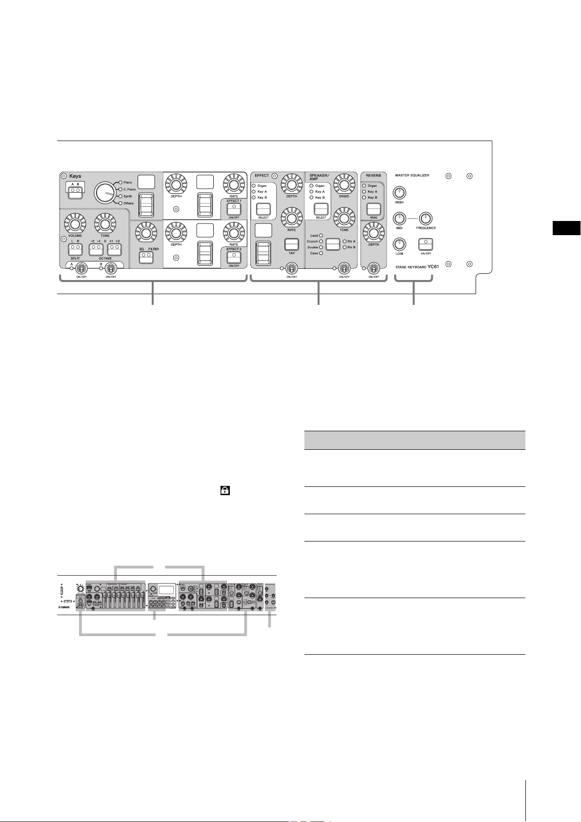
Controls and Functions
Keys (Key A, Key B) Sections
(page 16)
Master EQ
(page 19)
EFFECT, SPEAKER/AMP, REVERB
Sections (pages 17–19)
A
B
C
D
6 [EXIT] button
The MENU screens and the SETTINGS screens have a
hierarchical structure. Press this button to exit from the
current screen and return to the previous level. Also,
holding down this button and pressing other specific
buttons/knobs gives you access to a variety of convenient
shortcuts and quick operations (Special Operations;
page 31).
7 [PANEL LOCK] button
When this is set to “On,” control panel operations are
disabled, ensuring the settings cannot be inadvertently
changed. While the panel lock is engaged, will appear
on the top left corner of the LCD display.
NOTE
Panel lock settings can be made individually for the following
areas from the [MENU] button “Control Panel” “Panel Lock
Settings” (page 39).
A. Live Set
B. Organ/Keys
C. Effect/Sp Amp/Reverb
D. Master EQ
8 [TUNE] button
For setting the tuning for the entire instrument (414.72–
466.78 Hz, the default value is 440.00 Hz). Press the
[TUNE] button, and then use the Encoder dial to change
the value.
9 [TOUCH] button
For selecting curves that determine how the actual
velocities will be generated according your playing
strength. The following five types of settings are available.
The setting can also be changed from the [MENU] button
→ “General” → “Keyboard/Pedal” → “Touch Curve”
(page 38).
Settings Characteristics
Normal
Soft
Hard
Wide
Fixed
NOTE
Conventionally, organs do not respond to playing strength (key
velocity). Because of this, the Organ Section only produces a
fixed-velocity sound, regardless of playing strength, and the
settings of the [TOUCH] button do not affect the Organ Section.
This curve produces velocities in direct
proportion to the strength of your keyboard
playing. This is the most common type of curve.
This curve makes it easier to produce high
velocities across the entire keyboard.
This curve makes it more difficult to produce
high velocities across the entire keyboard.
This curve accentuates your playing strength by
producing lower velocities in response to softer
playing and louder velocities in response to
harder playing. You can use this setting to
expand the dynamic range of your performances.
This curve produces the same amount of sound
change, regardless of how hard or soft you play
the keyboard. The fixed velocity can be set from
the [MENU] button “General” “Keyboard/
Pedal” “Fixed Velocity.”
) [MENU] button
For calling up the screens for making overall system
settings (page 36).
YC61 Owner’s Manual
11
Page 12
Controls and Functions
!
@
#
$
%
^
Live Set Sound
20 pages
Live Set
Organ
Key A
Key B
EFFECT
SPEAKER/AMP
REVERB
SETTINGS
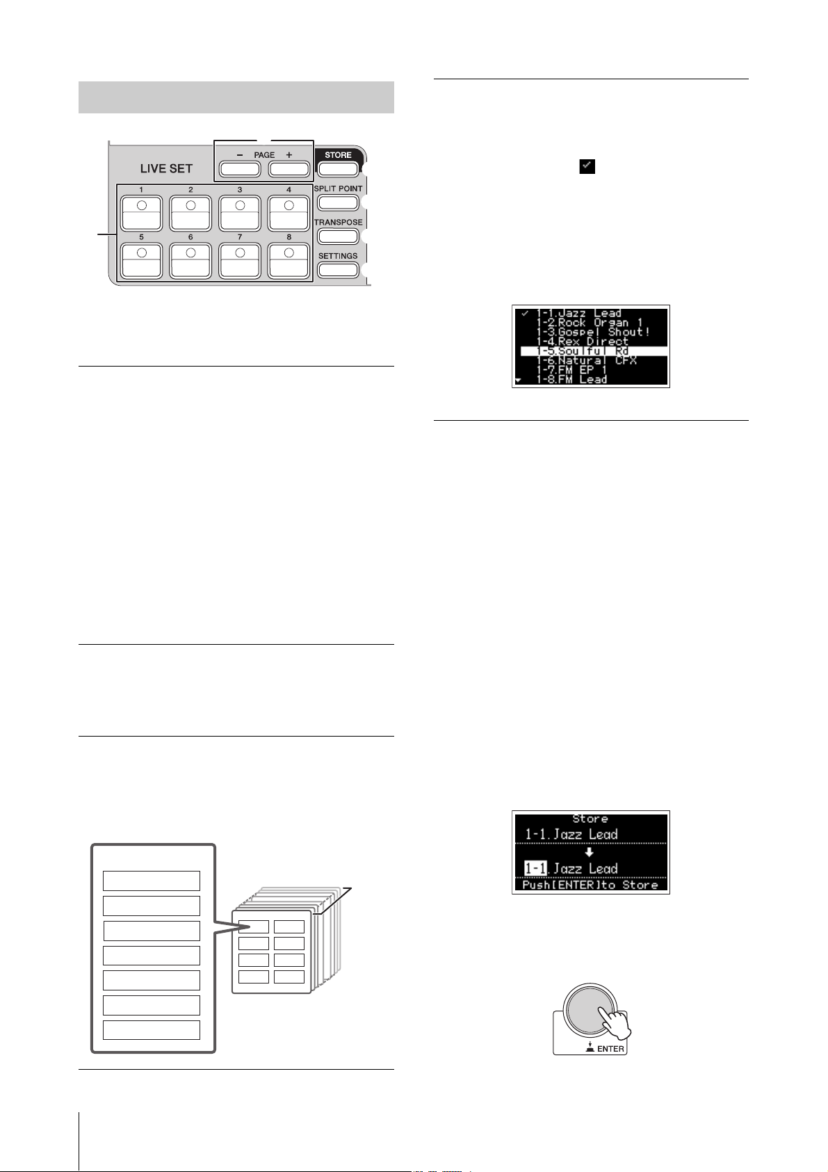
Live Set
! Live Set Sound [1]–[8] buttons
For calling up the stored Live Set Sounds.
Live Set Sound
The name “Live Set Sound” refers to sound settings that
include the Voices of the Organ Section (page 14) and
Keys Sections (Key A/Key B; page 16), the Effects of the
EFFECT Section (page 17) and SPEAKER/AMP Section
(page 18) and REVERB Section (page 19). You can freely
combine Voices and Insertion Effects to create and store
a custom Live Set Sound, and then easily call up that
sound. This instrument features an SSS (Seamless Sound
Switching) function to ensure that the sound does not
cut off even when switching the Live Set Sound, resulting
in a more natural performance.
NOTE
If you wish to mute the sound continued due to SSS, press the
currently selected Live Set Sound button again.
@ PAGE [-]/[+] buttons
For switching the Live Set Page. The Live Set Sound
changes accordingly.
Live Set View
Turn the Encoder dial when at the Top screen to open
the Live Set View. On the Live Set View, the names of the
Live Set Sounds [1]–[8] for one Live Set Page are
displayed in a screen. The indication will appear on
the left of the currently selected Live Set Sound. To
change the Live Set Sound in Live Set View, turn the
Encoder dial to select a Live Set Sound, and then press
the [ENTER] button. Once the change is made, it will
return automatically to the Top screen. To keep the Live
Set View displayed during performances, set “Live Set
View Mode” to “Keep” (page 39).
Live Set View Mode
# [STORE] button
For storing the edited Live Set Sound.
The following content is stored. Stored settings will be
retained when this instrument is turned off.
• Settings of the Organ Section
• Settings of the Key A and Key B Sections
• Settings of the EFFECT Section
• Settings of the SPEAKER/AMP Section
• Settings of the REVERB Section
• Settings in SETTINGS (including SPLIT POINT and
TRANSPOSE)
NOTE
Settings of the Master EQ cannot be stored in Live Set Sound.
Storing a Live Set Sound
Live Set
A Live Set combines Live Set Sounds [1]–[8] into a single
Live Set Page. A total of 20 pages can be stored. With the
default settings (factory settings), the preset Live Set
Sounds have been installed in the Live Set Pages 1–10.
YC61 Owner’s Manual
12
1.
Press the [STORE] button.
A screen for selecting the Live Set Sound to be stored
to appears.
2. Press the [ENTER] button to store the data.
“Completed.” appears on the screen, and then it
returns to the Top screen.
Page 13

Controls and Functions
NOTE
If you wish to store the currently edited settings to another
Live Set Sound, use the Encoder dial to select which Live
Set Sound to store the data to. You can confirm the sound of
that has already been stored in the destination by playing the
keyboard, before step 2.
NOTICE
• The settings will be overwritten if you change the
settings of an existing Live Set Sound (including one
of the preset Live Set Sounds) and then store those
changes. Proceed with caution, as the original
settings will be lost.
• The settings currently being edited will be lost if you
select a different Live Set Sound or turn off the power
before storing the settings.
NOTE
• If you selected a different Live Set Sound causing your
edits to be lost, you can use the “Edit Recall” function to
recall the last edited status (page 41).
• You can download the preset Live Set Sounds from
Soundmondo. Soundmondo is a service for managing
and sharing the Sound settings on an iOS application or
by using the Google Chrome browser on a Mac or PC. For
details, refer to the website below.
http://www.yamaha.com/2/soundmondo
Swapping/Copying Live Set Sounds
1. Call up the Live Set Sound you want to swap
from or copy.
2. Open the operating screen.
[MENU] button → “Job” → “Live Set Manager” →
“Swap”/ “Copy.”
Initializing the Live Set Sound
1. Call up the Live Set Sound you want to
initialize.
2. Open the initialization screen.
[MENU] button → “Job” → “Live Set Manager”→
“Initialize.”
3. Execute initialization.
Use the Encoder dial to select “Live Set Sound Init”
and then press the [ENTER] button. The messages
“Initializing..” → “Completed.” appears on the screen,
and then it returns automatically to the Top screen.
NOTE
If you want to reset the sound settings currently being edited
to the default state, press the [EXIT] and the [SETTINGS]
buttons simultaneously. This operation does not overwrite
the stored Live Set Sound.
$ [SPLIT POINT] button
For changing the Split Point. Turn the Encoder dial or
press the key you wish to assign as the Split Point. The
setting will be stored in the current Live Set Sound.
Split
The Split function allows you play different Voices with
the right and left hands. The point on the keyboard that
separates the right hand section and the left hand section
of the keyboard is called the “Split Point.”
NOTE
• You can also set by pressing the desired key while holding the
[SPLIT POINT] button.
• The note set as the Split Point becomes the lowest note of the
right hand section.
• The Split Point can also be changed from the [SETTINGS]
button “Function” “Split Point” (page 44).
3. Select the Live Set Sound you want to swap to
or copy to.
Use the Encoder dial to select the intended Live Set
Sound. Press the [ENTER] button. The messages
“Executing..” → “Completed.” appear on the screen,
and then operation returns automatically to the Top
screen.
% [TRANSPOSE] button
For adjusting the pitch in semitone steps. The settings
can be stored to the Live Set Sound. The settings can also
be changed from the [SETTINGS] button → “Sound” →
“Function” → “Transpose” (page 44).
^ [SETTINGS] button
For calling up the screens for making detailed settings
for the currently selected Live Set Sound (page 42). You
can make various settings, including the Organ
customization and Mono/Poly settings for Key A and
Key B. Settings made here are stored in the Live Set
Sound.
YC61 Owner’s Manual
13
Page 14
Controls and Functions
*
(
A
B
C
D
E
F
G
I
J
K
H
&
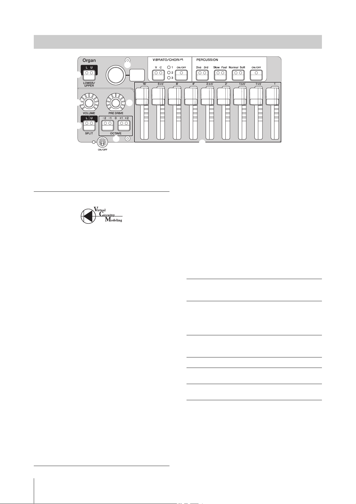
Organ Section
The YC61 Organ Section allows you to select an organ type from the VCM Organ tone generator that faithfully
reproduces a tonewheel-type vintage organ or an FM tone generator that reproduces a transistor-type organ, and uses
physical drawbars allowing you to perform while changing the organ sound in real time. You can also adjust the detailed
parameters to create an organ sound that includes differences between individual instruments etc.
VCM Organ tone generator
The VCM Organ tone generator was developed to
faithfully reproduce the sound of a tonewheel-type
vintage organ.
VCM stands for “Virtual Circuitry Modeling™,” and is
technology that uses DSP to emulate the functions of an
analog electric circuit. This technology enables the
instrument to reproduce sound with an analog-like
depth, which cannot be reproduced by a simple digital
sound.
By applying this technology, the VCM Organ tone
generator fully reproduces the following characteristics
of a vintage organ.
• Natural, organic harmonies when playing chords—
thanks to a matrix circuit that connects the keyboard,
tone wheels, and drawbars
• Percussion sound with remarkable presence—based on
vacuum tube circuit analysis
• Key clicks and leakage sounds—based on electrical
circuit analysis
• Natural sound distortion—simulating vintage vacuum
tube pre-amplifiers
• Vibrato/Chorus effect—from scanner-based vibrato
circuitry
• Changes in frequency characteristics and drive amount
that responds dynamically to operation of the
expression pedal
Adjustment of these detailed parameters makes it
possible to accurately recreate the distinctive
characteristics of the original instruments—including all
of their specially attractive imperfections, faults and even
deterioration.
& Section [ON/OFF] switch
To enable (turn on) or disable (turn off) this Section.
When this Section is enabled (on), the lamp lights up
and pressing a key generates sound.
* Organ type selector/display
Turn the Encoder dial to select the Organ type to be
used. The selected type (H1–H3, F1–F3) is shown on the
display.
H1–H3 indicate the VCM Organ types, while F1–F3
indicate the types using the FM tone generator.
H1
H2
H3
F1
F2
F3
The type setting is common to both LOWER and
UPPER parts.
NOTE
The organ sound characteristics (such as leakage level of the
tonewheel and volume of the key click sound) can be set from
the [SETTINGS] button “Sound” “Organ Settings”
(page 42). These settings are stored in the Live Set Sound.
This type faithfully reproduces a standard vintage
organ. It is fit for organ solos and music in which
the organ is the main instrument.
This type is characterized by its deep sound with
emphasis in the mid- to low-range tones. It is
ideal for when you want to have an edge or
presence that cuts through the rest of the band or
ensemble.
This type has a unique percussion sound.
This type works well with the drive effects, and is
suitable for playing fast passages.
This organ generates simple sine waves.
This type recreates a famous British transistor
combo organ.
This type recreates a famous Italian transistor
combo organ.
YC61 Owner’s Manual
14
Page 15

Controls and Functions
( LOWER/UPPER [L U] button
The Organ Section is divided into two parts: LOWER
and UPPER. Use this button to select which of those two
parts you want to display/change the settings of.
A SPLIT [L U] button
For selecting the setting whether each part of the Organ
sounds or not when you play each keyboard section
relative to the Split Point. Pressing the button alternates
sequentially between the four settings.
Off
L+U
U
L
NOTE
For details about the Split Point, refer to page 13.
The part selected by the LOWER/UPPER [L U]
button sounds, regardless of which key you play.
The LOWER part sounds when you play the left
section of the keyboard, and the UPPER part
generates sounds when you play the right section
of the keyboard.
The part selected by the LOWER/UPPER [L U]
button sounds only when you play the right
section of the keyboard. The LOWER/UPPER
[L U] is automatically changed to “U.”
The part selected by the LOWER/UPPER [L U]
button sounds only when you play the left section
of the keyboard. The LOWER/UPPER [L U] is
automatically changed to “L.”
B OCTAVE [-2 -1]/[+1 +2] buttons
To change the range of the keyboard in units of one
octave.
Press the [-2 -1] button and [+1 +2] button
simultaneously to restore the value to “0.” This can be set
separately for the LOWER and UPPER parts.
C [VOLUME] knob
For adjusting the volume of this Section. For the Organ
Section, this parameter is common to both the LOWER
and UPPER parts.
D [PRE DRIVE] knob
For changing the gain of the Organ pre-amplifier. It
models the changes in distortion caused by a preamplifier adjustment screw in the organ body. This
parameter is common to both the LOWER and UPPER
parts.
E Drawbars
For adjusting the composition of the Organ’s harmonics
and determine the character of the sound. When you
move a drawbar, the LED lights up to match the current
setting and the sound changes—as if you were pulling
out a drawbar on a vintage organ.
NOTE
• In situations like when you call up settings from the Live Set,
the actual position of the drawbars and the LED displays
(currently set values) will not match. If you move a drawbar,
that position will be reflected in the settings. Or, if you press
the LOWER/UPPER [L U] button while holding the [EXIT]
button, the values for the actual positions of all the drawbars
are immediately reflected in the settings without having to
move the drawbars.
• You can change the behavior for matching the actual
positions and the LED displays when drawbars are moved,
from the [MENU] button “Control Panel” “Advanced
Settings” “Drawbar Mode” (page 39).
• For organ types F1–F3, the 1' drawbar is disabled.
• You can set the color of the drawbar LEDs separately for the
LOWER and UPPER parts from the [SETTINGS] button
“Drawbar Color” “Upper”/ “Lower” (page 50). These
settings are stored in the Live Set Sound.
F VIBRATO/CHORUS [ON/OFF] button
Enables the vibrato/chorus effects (lamp lights when on).
These effects are only available for the VCM Organ types
(H1–H3), and can be set separately for the LOWER and
UPPER parts.
G VIBRATO/CHORUS type selection
button
For selecting the VIBRATO/CHORUS type. Pressing the
button alternates sequentially between V (vibrato) 1–3
and C (chorus) 1–3. This setting is common to both the
LOWER and UPPER parts.
H PERCUSSION [ON/OFF] button
Determines whether a percussion sound is generated or
not when a key is pressed. Percussion can be used only
with the UPPER part using the VCM Organ type (H1–
H3).
NOTE
You can set whether to link the percussion sound and the [1']
drawbar and only have one of them generate sound from the
[SETTINGS] button “Sound” “Organ Settings” “Perc.
Link to 1feet” (page 42). With default settings, this is set to “On.”
These settings are stored in the Live Set Sound.
I PERCUSSION [Normal Soft] button
For switching the level of the percussion sound.
J PERCUSSION [Slow Fast] button
For switching the decay speed of the percussion sound.
K PERCUSSION [2nd 3rd] button
For switching the pitch (harmonic) of the percussion
sound.
• When this is set to [2nd], pressing a key generates a
percussion sound at the same pitch as the [4'] drawbar
(2nd harmonic).
• When this is set to [3rd], pressing a key generates a
percussion sound at the same pitch as the [2 2/3']
drawbar (3rd harmonic).
YC61 Owner’s Manual
15
Page 16
Controls and Functions
Q
T
a
a
d
d
b
b
c
c
R
S
L
P
O
M
N
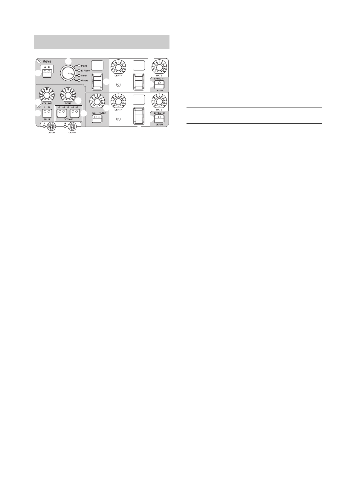
Keys (Key A/Key B) Section
The YC61 Keys Sections (Key A/Key B) allow you to
select a Voice for each Key from the four categories of
Piano, Electric Piano, Synth, and Other. Furthermore,
EG, FILTER, and two Insertion Effects (EFFECT 1,
EFFECT 2) can be set individually for each of the Key A
and Key B Sections. You can also make sound layers or
splits, using both Key A and Key B Sections
simultaneously.
P SPLIT [L R] button
Determines where the currently selected Section can be
played on the keyboard, with the Split Point as the basis.
Pressing the button alternates sequentially between the
three settings.
L+R
L
R
The Section sounds no matter where on the
keyboard you play.
The Section sounds only when you play the left
section of the keyboard.
The Section sounds only when you play the right
section of the keyboard.
Q OCTAVE [-2 -1]/[+1 +2] buttons
Determines the octave range of the keyboard for the
currently selected Section in units of one octave.
Press the [-2 -1] button and [+1 +2] button
simultaneously to restore the value to “0.”
R [VOLUME] knob
For adjusting the volume of the currently selected
Section.
L Section [ON/OFF] switch
For enabling (turning on) or disabling (turning off) the
Key A and Key B Sections, respectively.
M Keys [A B] button
For selecting which of the Key A and Key B Sections you
want to display/change the settings of.
NOTE
• You can switch the settings of the Key A and Key B Sections
by pressing the [EXIT] + Keys [A B] buttons (page 31).
• If both the Key A and Key B Sections are off, nothing will be
displayed if this button is pressed.
You can also set so that the settings are displayed even when
these Sections are off. Set the value under the [MENU] button
“Control Panel” “Display Lights” “Section” to “On”
(page 39).
N Voice category selector
For selecting the Voice category to be used in the
currently selected Section.
O Voice selection switch/display
For selecting one of the Voices of the category selected
with the Voice category selector. The currently selected
Voice number is displayed. Operating this switch while
holding the [EXIT] button moves to the top of next/
previous Voice subcategory (page 31).
For a list of Voices available for the Key A and Key B
Sections, refer to page 58.
S [TONE] knob
For adjusting the tone of the currently selected Section.
When the knob is in the center, the tone is flat. Turn the
knob to the right to boost the higher and lower ranges,
or turn it to the left to cut them.
T [EG FILTER] button/knob
The knob here lets you adjust (with a convenient, single
control) the EG or FILTER of the currently selected
Section, while pressing the button selects the specific
parameter for knob control (EG or FILTER).
NOTE
The EG and FILTER control types for each of the Key A and
Key B Sections can be selected from different types of changes.
Change the types by operating the [EXIT] button + [EG FILTER]
knob, or from the [SETTINGS] button “Sound” “Key A
Settings”/ “Key B Settings” “EG Control”/ “Filter Control.”
For details on the EG/Filter control types, see page 34.
a EFFECT 1/2 [ON/OFF] button
For turning the Insertion Effects on or off. To use the
effects, set this to ON.
NOTE
To check the effect settings while the Insertion Effects are set to
off, set the value under the [MENU] button “Control Panel”
“Display Lights” “Ins Effect” to “On” (page 39).
YC61 Owner’s Manual
16
Page 17
Controls and Functions
PRE DRIVE EFFECT 1 EFFECT 1
Ins. Effect
SPEAKER/AMP Section
Send
level
Reverb Section
Master EQ
EFFECT Section
Organ Key A Key B
EFFECT 2 EFFECT 2
Ins. Effect
b Effect type selection switch/display
Use this switch to select the type of Insertion Effects. The
type name currently selected is displayed using two
characters.
The Effect types that can be selected in EFFECT 1/2 and
the EFFECT Section are different. For a list of the
available Effect types, refer to page 32.
Operating this switch while holding the [EXIT] button,
moves to the top of next/previous Effect category
(page 31).
c [DEPTH] knob
For adjusting the depth or other parameters of the
Insertion Effects.
d [RATE] knob
For adjusting the speed or other parameters of the
Insertion Effects. The parameter to be adjusted differs
for each effect type. For details, see page 32.
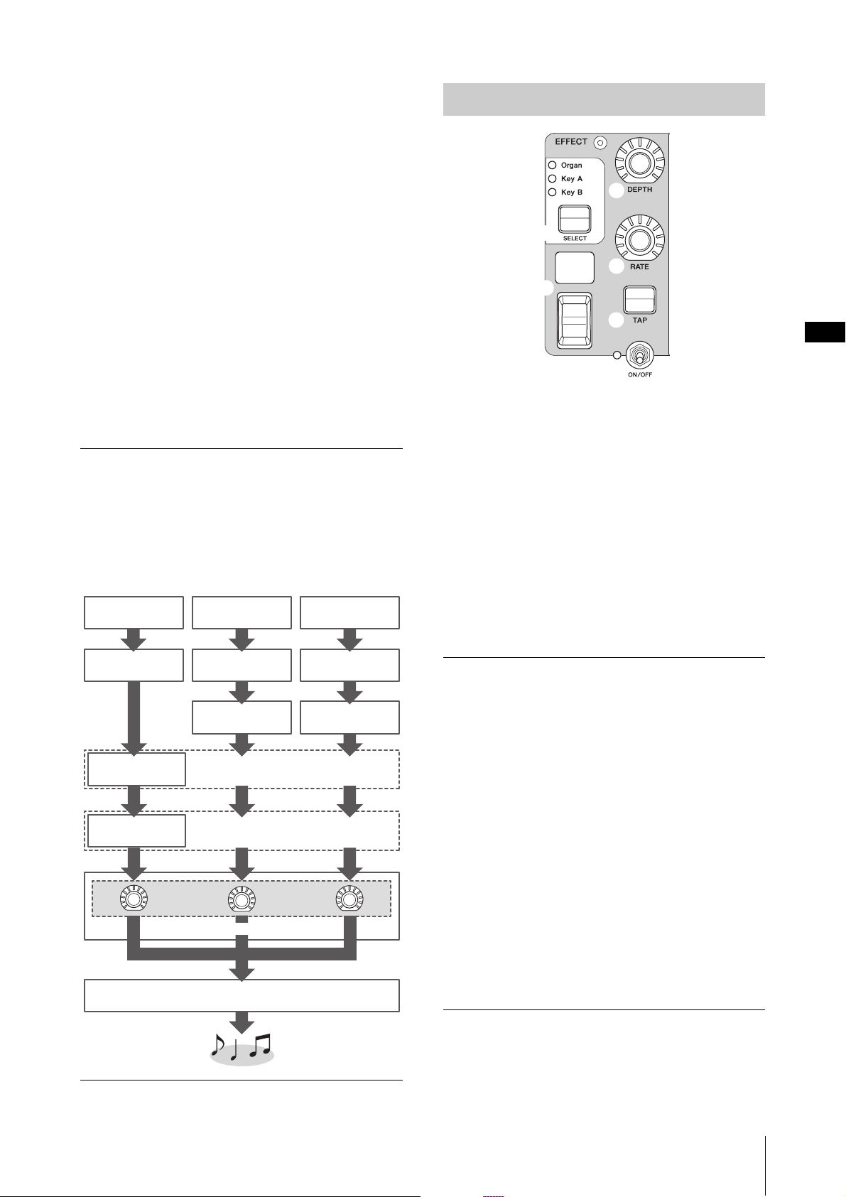
Effect
The YC61 features Insertion Effects that can be set
individually for each of the Key A and Key B Sections,
Insertion Effects that can be set for either Voice Section,
and a reverb effect and Master EQ that can be set for all
Voice Sections simultaneously. The illustration below
shows the audio signal path.
EFFECT Section
c
f
d
b
g
e
The EFFECT Section allows you to apply an Insertion
Effect to either the Organ, Key A, or Key B Section.
There are also two types exclusive to this Section: Tempo
Delay and Looper Delay. For a list of the available effect
types, refer to page 32.
e Section [ON/OFF] switch
For enabling (turning on) or disabling (turning off) the
EFFECT Section. The lamp is lit up when effects are
applied.
f [SELECT] button
For selecting the Section to which the Insertion Effects
will be applied.
About Looper Delay
When the Looper Delay type (page 33) is selected, the
EFFECT Section behaves differently from normal:
• The Looper Delay effect is applied after the SPEAKER/
AMP Section. In addition, the effect of the REVERB
Section is not applied to the delay sound.
• The status of the [SELECT] button lamps have a
different meaning than normal. Pressing the
[SELECT] button alternates between the two states
(below).
All lit: The delay effect is applied to all the Organ,
Key A, and Key B Sections, and the sound you play is
added to the Looper.
All off: The delay effect is not applied to any of the
Sections, and the sound you play will not have any
Looper effect. Using this lets you effectively create a
rhythmic delay “loop” as you play, and then stop
adding to it so you can play phrases over it while the
loop continues.
YC61 Owner’s Manual
17
Page 18
Controls and Functions
g [TAP] button
Use this button to control the speed (tempo) when the
“Tempo Delay” type is selected. Tap this button three
times or more to change the tempo.
You can also change the “Tempo Delay Time” (page 45)
by turning the [RATE] knob while holding the [EXIT]
button.
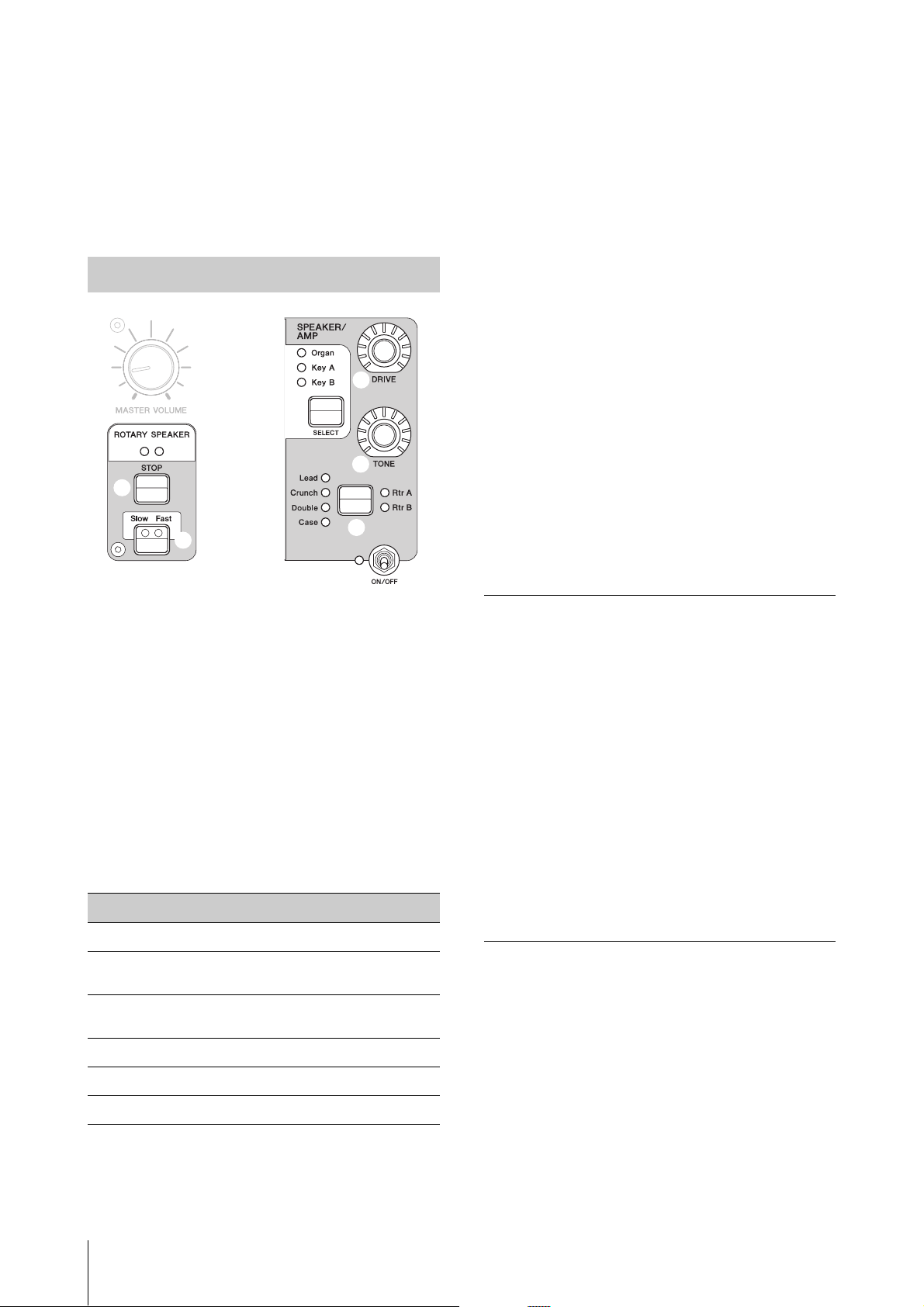
SPEAKER/AMP Section
j
f
n
k
m
i
l
h
tune the status of the rotary speaker from [SETTINGS] button
“Sound” “Rotary Speaker” (page 44).
• Rtr A and Rtr B use monaural input and stereo/monaural
output. Select whether to use stereo output or monaural
output from [SETTINGS] button “Sound” “Rotary
Speaker” “Stereo/Mono.”
• Lead, Crunch, Double, and Case use stereo input and stereo
output.
j [DRIVE] knob
For adjusting the amount of distortion in the speaker/
amp sound. Turn this knob to the right to increase the
distortion.
k [TONE] knob
For adjusting the tone of the speaker/amp sound. When
the knob is in the center, the tone is flat. Turn to the
right to boost treble and cut bass. Turn to the left to
boost bass and cut treble.
l [Slow Fast] button
For switching the rotation speed of the rotary speaker.
Pressing the [Slow Fast] button while a type other than
Rtr A or Rtr B is selected automatically selects the Rtr A
type. In addition, pressing this button will automatically
turn the SPEAKER/AMP Section on even if the Section
itself is off.
The SPEAKER/AMP Section allows you to apply speaker
or amp-related Insertion Effect to either the Organ,
Key A, or Key B Section. The rotary speaker type
faithfully reproduces switching between slow and fast,
and the behavior when stopping.
h Section [ON/OFF] switch
For enabling (turning on) or disabling (turning off) the
SPEAKER/AMP Section. The lamp is lit up when effects
are applied.
i Effect type switching button
Alternates between the following effects. The lamp for
the selected effect lights.
Effect Description
Rtr A
Rtr B
Lead
Crunch
Double
Case
NOTE
• If you have selected either the Rtr A or Rtr B type, you can
use the ROTARY SPEAKER [STOP]/[Slow Fast] button to
control the operation of the rotary speaker. You can also fine-
Standard rotary speaker for organ.
Rotary speaker connected to a transistor
preamplifier with strong distortion.
Guitar amp that features a bass of high sound
pressure, and a sharp treble.
Guitar amp that features a crunch sound.
Guitar amp that features a bright sound.
Speaker amp for a vintage electric piano.
Controllers that can be used for switching the
Slow/Fast
The rotary speaker rotation speed switching function can
also be assigned to the following controllers.
•Bend Lever
•Modulation Lever
•FOOT CONTROLLER [1]
•FOOT CONTROLLER [2]
• FOOT SWITCH [SUSTAIN]
• FOOT SWITCH [ASSIGNABLE]
The function of the FOOT SWITCH [ASSIGNABLE]
can be set via the [MENU] button → “General” →
“Keyboard/Pedal” → “Foot Switch Assign” (page 38).
The function of the other controllers can be set via the
[SETTINGS] button → “Controllers” (page 49).
m [STOP] button
For stopping the rotation of the rotary speaker. Pressing
and holding the button for a few seconds immediately
stops the rotary speaker, and resets the position.
n [ROTARY SPEAKER] lamp
This lamp gives you visual indication of the rotation
speed of the rotary speaker, by flashing in time with the
speed.
YC61 Owner’s Manual
18
Page 19

Controls and Functions
o
p
q
r
s
t
u
v
REVERB Section
The REVERB Section applies a reverb effect to all Voice
Sections, creating a rich, special ambience as if you are
playing in a concert hall or other performance space.
o Section [ON/OFF] switch
For enabling (turning on) or disabling (turning off) the
REVERB Section. The lamp is lit up when effects are
applied.
Master EQ
Master EQ adjusts the tone of the overall sound.
r MASTER EQUALIZER [ON/OFF] button
To enable (turn on) or disable (turn off) the Master EQ.
The lamp is lit up when Master EQ is applied.
NOTE
The Master EQ settings cannot be stored in Live Set Sound.
s [HIGH] knob
For setting the gain (-12 to +12) of the high range
(5 kHz).
p [SEND] button
Determines the Section for adjusting the Send level of
the reverb effect. When all three lamps are lit up, you can
equally adjust the send level for each Section.
q [DEPTH] knob
For adjusting the send level (effect depth) of the reverb
effect for the Section selected with the [SEND] button.
t [MID] knob
For setting the gain (-12 to +12) of the middle range (100
to 10 kHz).
u [FREQUENCY] knob
For setting the center frequency of the middle range.
v [LOW] knob
For setting the gain (-12 to +12) of the low range
(80 Hz).
YC61 Owner’s Manual
19
Page 20

Rear Panel
1
2
4
3
AC outlet
USB flash drive
Computer
1 [STANDBY/ON] switch
For switching the instrument to standby or turning it on.
2 [AC IN] jack
For connecting the supplied AC power cord.
3 USB [TO DEVICE] terminal
For connecting a USB flash drive to this instrument,
allowing you to use the device to save data you have
created and load data you want to restore.
NOTE
Only a USB flash drive can be recognized by this instrument. No
other USB devices (such as a hard disk drive, CD-ROM drive or
USB hub) can be used.
4 USB [TO HOST] terminal
For connecting this instrument to a computer, iPhone or
iPad via a USB cable, allowing you to transfer MIDI data
and audio data between the devices. Unlike the
communication via the MIDI [IN]/[OUT] terminals,
this terminal can handle two MIDI ports via a single
cable. For more information on these two MIDI ports,
see page 28.
NOTE
• Audio data sending capability for the instrument is a maximum
two channels (one stereo channel) at a sampling rate of
44.1 kHz, 24 bit.
• For details on connecting an iPhone or iPad, refer to page 29.
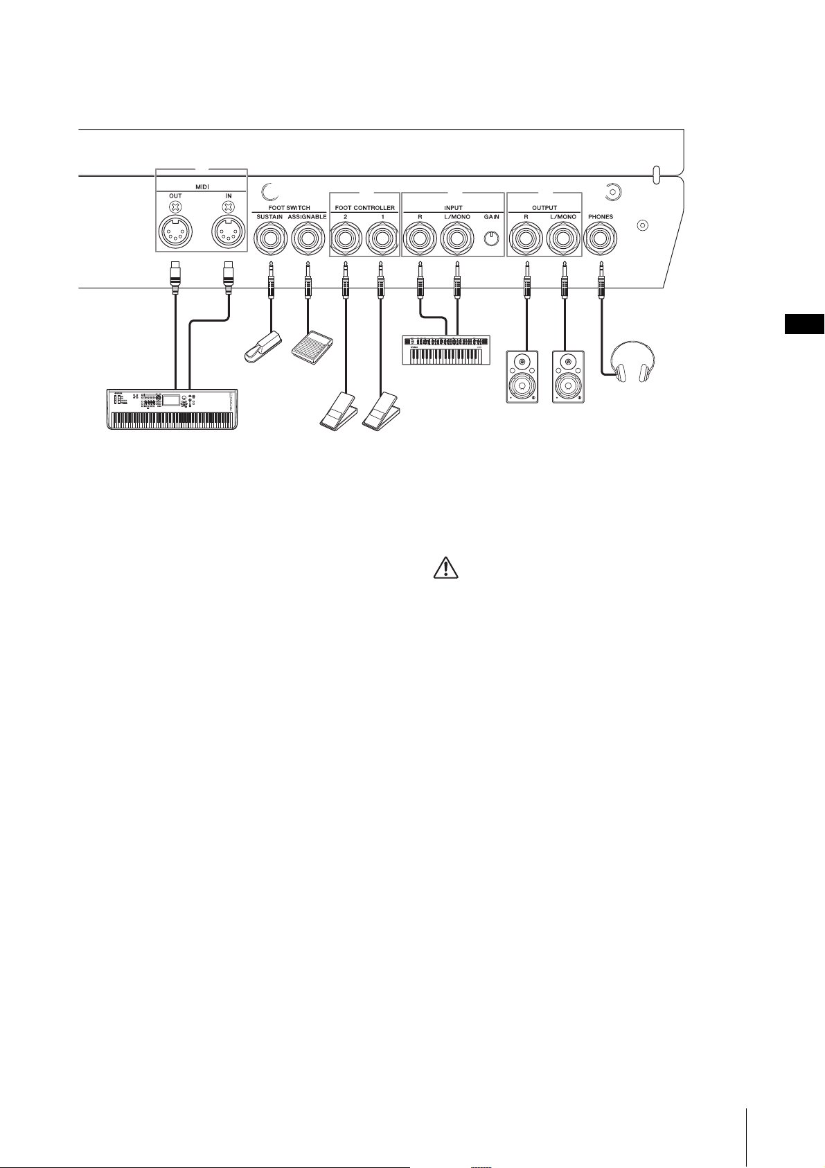
5 MIDI [IN]/[OUT] terminals
With a standard MIDI cable (commercially available),
you can connect an external MIDI instrument, and
control it from this instrument. Likewise, you can use an
external MIDI device (such as a keyboard or sequencer)
to control the sounds on this instrument.
6 FOOT SWITCH [SUSTAIN] jack
For connecting an FC3A Foot Switch (sold separately)
for use as a dedicated Sustain pedal.
You can also switch assignments to use the same
function as the ROTARY SPEAKER [Slow Fast] button
(page 18) instead of the Sustain function. Function
assignment can be set from the [SETTINGS] button →
“Controllers” → “Sustain Pedal.”
7 FOOT SWITCH [ASSIGNABLE] jack
For connecting a separately sold foot switch (FC4A or
FC5) in order to perform a range of freely assignable
functions such as a soft pedal, sostenuto pedal, and
switching Live Set Sounds. In the default settings, “Live
Set+” is assigned.
You can assign functions from the [MENU] button →
“General” → “Keyboard/Pedal” → “Foot Switch Assign”
(page 38). Refer to page 60 for a list of the parameters
that can be assigned to this instrument.
20
YC61 Owner’s Manual
Page 21
Controls and Functions
6 7 !
5
8 9 )
External MIDI keyboard, etc.
FC3A,
FC4A,
FC5
FC4A,
FC5
FC7
External
synthesizer, etc.
Keyboard amplifier
or
Monitor speakers
Headphones
8 FOOT CONTROLLER [1]/[2] jacks
For connecting a separately sold foot controller (FC7),
which conveniently lets you continuously control one of
various different assignable functions with your foot—
such as volume and the tone of Voice Sections. In the
default settings, “Expression” is assigned to FOOT
CONTROLLER [1], and “Pedal Wah” is assigned to
FOOT CONTROLLER [2].
You can assign functions to the foot controller from the
[SETTINGS] button → “Controllers” → “Foot Controller
1” / “Foot Controller 2” → “Assign.” Refer to page 60 for
a list of the parameters that can be assigned.
9 INPUT [L/MONO]/[R] jacks/[GAIN] knob
These jacks allow you to connect an external audio
devices and mix the output of that device with that of
this instrument. Use the [GAIN] knob to adjust the
volume balance with this instrument.
) OUTPUT [L/MONO]/[R] jacks
Use these two 1/4" standard mono phone (unbalanced)
jacks together to output stereo audio signals. When
using mono output, connect only to the [L/MONO]
jack.
! [PHONES] jack
Use this 1/4" standard stereo phone jack to connect a
pair of headphones.
CAUTION
• To prevent hearing loss, avoid using headphones at high
volumes for extended periods of time.
• Whenever connecting other audio equipment, ensure that
all devices are turned off.
NOTE
The sound output via the headphones is identical to that output
via the OUTPUT [L/MONO]/[R] jacks. Furthermore, plugging in
or disconnecting a set of headphones has no effect on whether
the sound is output via these jacks.
YC61 Owner’s Manual
21
Page 22
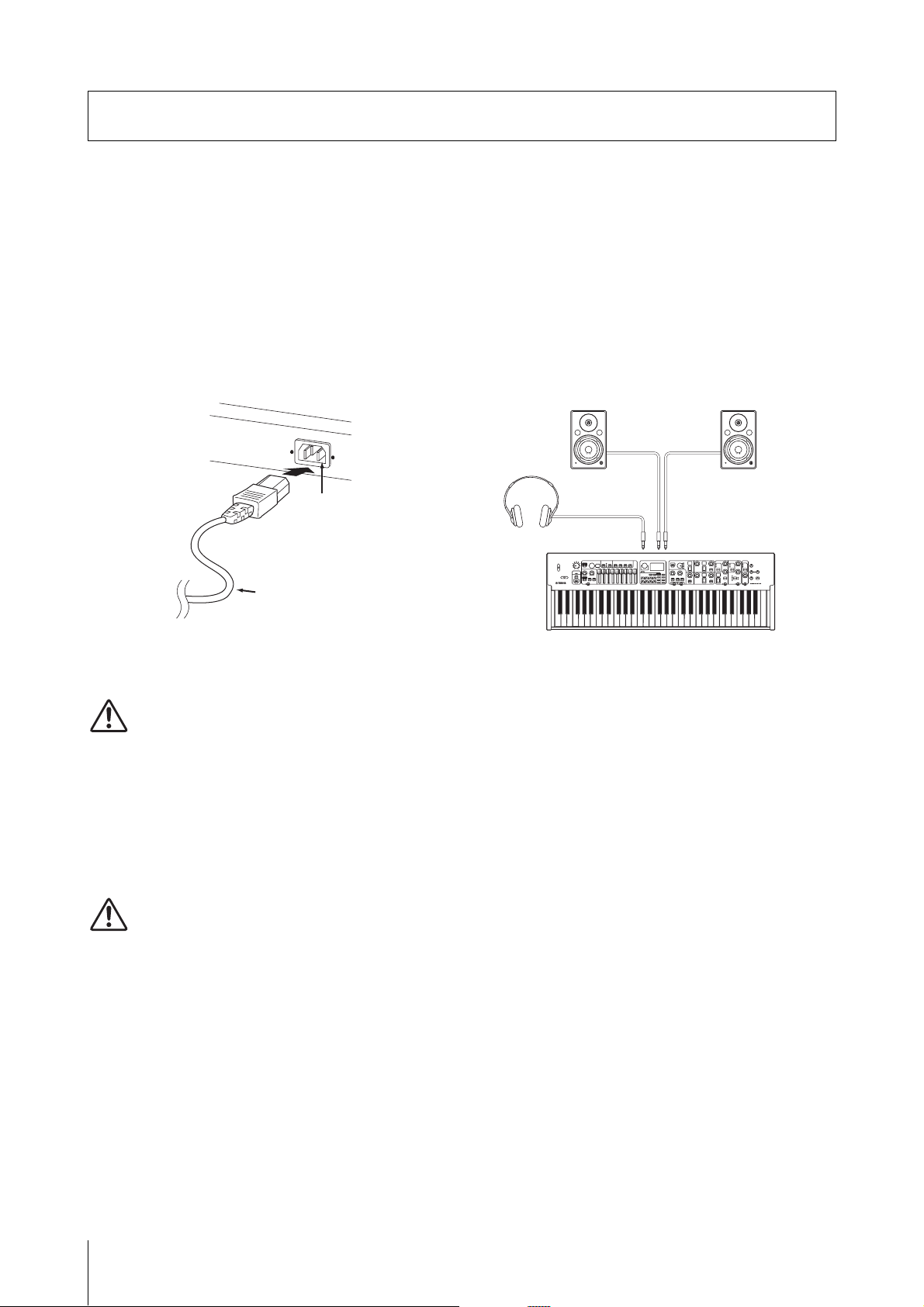
Setting Up
[AC IN] jack
Power cord (included)
Rear panel
Keyboard amplifier or monitor speaker
(left) (right)
Headphones
OUTPUT
[L/MONO] jack
OUTPUT
[R] jack
[PHONES] jack
Setting Up
Power Supply
Connect the respective ends of the supplied AC power
cord in the following order. Make sure the [STANDBY/
ON] switch on the instrument is set to the STANDBY
position.
1. Connect the supplied power cord to the
[AC IN] jack on the instrument’s rear panel.
2. Connect the other end of the power cord to an
AC outlet.
Connecting Speakers or Headphones
Since the instrument has no built-in speakers, you will
need to monitor the sound of the instrument by using
external equipment. Connect a set of headphones,
monitor speakers, or other playback equipment as
illustrated below. When making connections, be sure
that your cables have the appropriate ratings.
NOTE
Follow this procedure in reverse order when disconnecting the
power cord.
WARNING
• Use only the AC power cord supplied with your
instrument. The use of an inappropriate replacement can
lead to overheating or electric shock.
• The power cord supplied with your instrument must not
be used with other electrical equipment. Failure to
observe this precaution can result in damage to the
equipment or fire.
• Make sure your instrument the voltage requirement for
the country or region in which it is being used.
CAUTION
The instrument remains charged and draws a small amount
of power even when the [STANDBY/ON] switch is set to the
STANDBY position. If you intend not to use it for an
extended period of time, therefore, make sure to unplug the
power cord from the wall outlet.
Turning On and Off
Make sure the volume settings of the instrument and
external devices such as powered speakers are turned to
the minimum before turning the power on. When
connecting the instrument to monitor speakers, turn on
the power switch of each device in the following order.
Turning on
Turn the [MASTER VOLUME] knob of this instrument
to its minimum (left-most setting) → set the [STANDBY/
ON] switch to ON → turn the amplifier or speaker power
on.
Turning off
Turn the [MASTER VOLUME] knob of this instrument
to its minimum (left-most setting) → turn the amplifier
or speaker power off → set the [STANDBY/ON] switch
to STANDBY.
22
YC61 Owner’s Manual
Page 23
Basic Structure & Display Content
1
23
Auto Power Off Function
The Auto Power Off function automatically turns off
this instrument after 30 minutes of inactivity. By default,
this is set to “Disable.”
Setting the Auto Power Off function
[MENU] button → “General” → “Auto Power Off” →
“Enable” (page 38).
NOTICE
• Since any unsaved data will be lost when the Auto Power
Off function turns off this instrument. Make sure to store
your work before this occurs.
• Depending on the instrument status, the power may not
turn off automatically, even after the specified period of
time elapses. Always turn off the power manually when
the instrument is not in use.
Basic Structure & Display Content
Restoring the Factory Default Settings (Factory Reset)
The Factory Reset function allows you to restore this
instrument to its initial condition. To execute the factory
Reset function, press the [MENU] button → “Job” →
“Factory Reset.”
NOTICE
When the Factory Reset function is executed, all the Live
Set Sounds and the settings of MENU screens and
SETTINGS screens will be overwritten with their defaults. It
is wise, therefore, to regularly create backup copies of
important data on a USB flash drive or the like.
NOTE
Refer to page 56 for information on detailed settings of preset
Live Set Sounds.
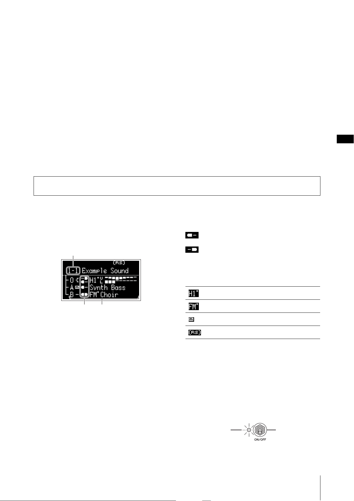
Top Screen Configuration
This section explains the Top (Live Set Sound) screen
which appears when this instrument is turned on with its
default settings (factory settings).
1 Live Set Sound number
Displays the currently selected Live Set Sound number.
The “1-1” is selected automatically when this instrument
is turned on. You can also change which number is
automatically selected when turned on, by changing the
“Power On Sound” setting (page 40).
2 Voice Sections
Indicates the status of each Section.
The sound of this instrument is divided into three Voice
Sections: Organ, Key A, and Key B. The Organ (O) area
shows the organ type and the approximate drawbar
settings, while the Key A (A) and Key B (B) areas show
the Voice names.
Voices having “FM” in the name are those using FM
tone generation.
The Sections set to on will sound simultaneously in a
layer. The Sections set to off are not displayed on the
Top Screen and will not sound.
3 Split
Indicates the current split status of each Voice Section/
part.
indicates that the Section/part sounds when the
keyboard is played in a range below the Split Point.
indicates that the Section/part sounds when the
keyboard is played in a range above the Split Point.
In addition, following special icons may appear on the
Top screen depending on the Live Set Sound settings.
“Organ Settings” (page 42) are customized.
“FM Unison” “Mode” (page 43) is set.
“Mono/Poly” (page 43) is set to “Mono.”
“Rotary Speaker” settings (page 44) are customized.
Selecting Voice Sections
To enable (ON) or disable (OFF) each Voice Section, use
the corresponding Section [ON/OFF] switch. When the
indicator lamp of the Section [ON/OFF] switch is lit, the
corresponding Voice Section will sound when you play
the keyboard. When multiple Sections are set to on,
those Sections will sound simultaneously in a layer.
YC61 Owner’s Manual
23
Page 24

Exiting from the Current
Cursor
Desired character
Screen
The MENU screens and the SETTINGS screens are
arranged in a hierarchical structure. To move one step
back to the previous hierarchy, press the [EXIT] button.
Pressing the [EXIT] button several times will return you
to the Top (Live Set Sound) screen.
Use the Live Set Sound [1]/[2] buttons to move the
cursor to the position of the character you wish to edit.
Use the Encoder dial to select characters, and then use
the following buttons to edit the name.
Button/Indication Functions
Live Set Sound [1]
Live Set Sound [2]
Moves the cursor to left.
Moves the cursor to right.
Editing File Names/Live Set Sound Names
Editing File Names
[MENU] button → “File” → “File Utility” → “Rename” →
Select the desired file for which you wish to edit the
name → Edit the name → [ENTER] button to save the
file.
Editing Live Set Sound Names
Select the desired Live Set Sound for which you wish to
edit the name → [SETTINGS] button → “Name” → Edit
the name → [ENTER] button → Select “Store”/ “Do not
store now.”
Live Set Sound [3]
Live Set Sound [4]
Live Set Sound [5]
Live Set Sound [7]
Live Set Sound [8]
[ENTER]
[EXIT]
Inserts a desired character at the
cursor position.
Deletes the character at the cursor
position.
Changes the character at the cursor
position to the desired one.
Reverts all characters to the unedited
name.
Deletes all characters.
Terminates the edit operation, and
then stores the data or saves the file.
Terminates the edit operation.
NOTE
If “Do not store now” is selected, the Live Set Sound will not be
stored, but the edited name will remain.
Operations During Name Edit
YC61 Owner’s Manual
24
Page 25

Saving / Loading Data
File name edit screen
Saving / Loading Data
In the File screens ([MENU] button → “File”), you can save/load the data of this instrument, including the entire system
settings, entire Live Set, or each Live Set Sound to/from a USB flash drive.
NOTE
Before using a USB flash drive, be sure to read “Precaution when using the USB [TO DEVICE] terminal” (page 26).
Saving the settings to a USB flash drive
1. Connect a USB flash drive to the USB [TO
DEVICE] terminal of this instrument.
2. Call up the File screen.
Select the [MENU] button → “File.”
3. Select the contents you wish to save.
The following file types can be saved to a USB flash
drive.
File type Description
Back Up File
Live Set All File
Live Set Page File
Live Set Sound File
4. Perform the save operation.
Select “Save” and press the [ENTER] button to call up
the screen for selecting the destination.
When overwriting the existing file
Select the desired file from the displayed list.
All data including the system
settings.
All the Live Set Pages.
Currently selected Live Set
Page.
Currently selected Live Set
Sound.
Loading the settings from a USB flash drive
NOTICE
The Load operation overwrites any data previously existing
in this instrument. Important data should always be saved
to a USB flash drive connected to the USB [TO DEVICE]
terminal.
1. Connect a USB flash drive to the USB [TO
DEVICE] terminal of this instrument.
2. Call up the File screen.
Select the [MENU] button → “File.”
3. Select the contents you wish to load from the
USB flash drive.
File type Description
Back Up File
(Extension: .Y0A)
Live Set All File
(Extension: .Y0L)
Live Set Page File
(Extension: .Y0P)
Live Set Sound File
(Extension: .Y0S)
All data including system
settings.
All Live Set Pages.
One Live Set Page. The file will
be loaded to the currently
selected Live Set Page.
One Live Set Sound. The file
will be loaded to the currently
selected Live Set Sound.
When saving as a new file
Select “New File.”
The “Save *** File” screen for editing file name
appears. For details on name editing operations, refer
to “Operations During Name Edit” (page 24).
Press the [ENTER] button to execute saving. The
messages “Saving..” → “Completed.” will appear on
the screen, and then return to the Top screen.
4. Select “Load” and press the [ENTER] button.
5. Select the file in the USB flash drive.
To cancel the loading operation, select “Cancel” and
press the [ENTER] button.
6. Perform the load operation.
Select “Load All”/ “Load to ***” and then press the
[ENTER] button. The messages “Loading..” →
“Completed.” will appear on the screen, and then
return to the Top screen.
NOTE
For file types other than a Live Set Sound file, you can select
and load the one desired Live Set Sound included in the file.
In that case, select “Load Live Set Sound” in step 6 to call up
the screen for selecting the Live Set Sound in the file. Then
select the desired data, and execute loading. The data is
loaded into the currently selected Live Set Sound.
YC61 Owner’s Manual
25
Page 26

Saving / Loading Data
Precautions when using the USB
[TO DEVICE] terminal
This instrument features a built-in USB [TO
DEVICE] terminal. When connecting a USB device
to the USB [TO DEVICE] terminal, be sure to
handle the USB device with care. Follow the
important precautions below.
NOTE
For more information about the handling of USB devices,
refer to the owner’s manual of the USB device.
Compatible USB devices
• USB flash drive
Other USB devices such as a USB hub, computer
keyboard or mouse cannot be used.
The instrument does not necessarily support all
commercially available USB devices. Yamaha cannot
guarantee operation of USB devices that you purchase.
Before purchasing a USB device for use with this
instrument, please visit the following web page:
https://download.yamaha.com/
Although USB devices 2.0 to 3.0 can be used on this
instrument, the amount of time for saving to or loading
from the USB device may differ depending on the type
of data or the status of the instrument.
NOTICE
The rating of the USB [TO DEVICE] terminal is a
maximum of 5V/500mA. Do not connect USB devices
having a rating above this, since this can cause damage
to the instrument itself.
Connecting a USB device
When connecting a USB device to the USB [TO
DEVICE] terminal, make sure that the connector on
the device is appropriate and that it is connected in the
proper direction.
NOTICE
• Avoid connecting or disconnecting the USB device
during playback/recording and file management
operations (such as Save, Copy, Delete and Format),
or when accessing the USB device. Failure to
observe this may result in “freezing” of the operation
of the instrument or corruption of the USB device and
the data.
• When connecting then disconnecting the USB device
(and vice versa), make sure to wait a few seconds
between the two operations.
• Do not use an extension cable when connecting a
USB device.
Formatting a USB flash drive
You should format the USB flash drive only with this
instrument (page 41). A USB flash drive formatted on
another device may not operate properly.
NOTICE
The format operation overwrites any previously existing
data. Make sure that the drive you are formatting does
not contain important data.
To protect your data (write-protect)
To prevent important data from being inadvertently
erased, apply the write-protect provided with each USB
flash drive. If you are saving data to the USB flash drive,
make sure to disable write-protect.
Turning off the instrument
When turning off the instrument, make sure that the
instrument is NOT accessing the USB flash drive by file
management (such as during Save, Copy, Delete and
Format operations). Failure to do so may corrupt the
USB flash drive and the data.
Precautions when using the USB [TO
HOST] terminal
When connecting the computer to the USB [TO
HOST] terminal, make sure to observe the following
points to avoid freezing the computer and corrupting
or losing the data.
NOTICE
• Use an AB type USB cable. USB 3.0 cables cannot be
used.
• Execute the following before turning the power to the
instrument on/off or plugging/unplugging the USB
cable to/from the USB [TO HOST] terminal.
- Quit any open application software on the
computer.
- Make sure that data is not being transmitted from
the instrument. (Data is transmitted only by playing
notes on the keyboard.)
• While the computer is connected to the instrument,
you should wait for six seconds or more between
these operations: (1) when turning the power of the
instrument off then on again, or (2) when alternately
connecting/disconnecting the USB cable.
If the computer or the instrument freezes, restart the
application software or the computer OS, or turn the
power to the instrument off then on again.
Using USB flash drives
By connecting the instrument to a USB flash drive, you
can save data you’ve created to the connected device, as
well as read data from the connected device.
• Number of USB flash drives that can be used
Only one USB flash drive can be connected to the
[USB TO DEVICE] terminal.
YC61 Owner’s Manual
26
Page 27

Using with External Devices
MIDI [IN] terminal
External MIDI keyboard, stage piano, etc.
MIDI [OUT] terminal
YC6 1
MIDI [IN] terminal
Synthesizer or tone generator module, etc.
MIDI [OUT] terminal
YC6 1
Using with External Devices
By using the MIDI [IN]/[OUT] terminals and the USB [TO HOST] terminal, you can connect various kinds of external
devices to this instrument.
• MIDI [IN]/[OUT] terminals: Connecting the instrument to an external MIDI device (synthesizer, tone generator
module, etc.), and transmit/receive MIDI data.
• USB [TO HOST] terminal: Connecting the instrument to a computer or iPhone/iPad, and transmit/receive MIDI and
audio data.
These can be combined for use with the instrument in various ways.
NOTE
Before connecting the USB [TO HOST] terminal to a computer or the like, be sure to read “Precautions when using the USB [TO HOST]
terminal” on page 26.
Controlling this instrument
from an external MIDI
keyboard or stage piano
You can use the external MIDI keyboard instead of the
keyboard of this instrument to play and control each
Section of this instrument. To specify which Section/part
will sound when you play an external MIDI keyboard,
make settings via the [SETTINGS] button → “External
Keyboard” (page 45).
You can also use these to recreate a two-manual organ,
by setting only one of the UPPER/LOWER parts in the
Organ Section to be controlled from an external MIDI
keyboard. For example, if you want to play the UPPER
part of the Organ Section with the keyboard of this
instrument and play the LOWER part with an external
MIDI keyboard, set “External Keyboard” to
“2manualLo.”
You can also use the controllers of the Sections that is
turned off to control external devices by setting the
“MIDI Control” (page 37) to “Invert.”
Using by connecting to a
computer or an iPhone/iPad
By connecting to a computer or an iPhone/iPad, you can
use this instrument for following usages:
Controlling a synthesizer or
tone generator module from
this instrument
You can play the sounds of an external MIDI tone
generator by playing on this instrument's keyboard.
Controlling this instrument from a
computer or iPhone/iPad
You can play or control the Sections of this instrument
from a DAW software etc. on your computer or iPhone/
iPad. Audio data can also be transmitted/received.
Controlling a synthesizer or tone
generator module from a computer or
iPhone/iPad
By using the YC61 as a USB-MIDI interface, you can
play the sound of other MIDI tone generator from a
DAW software etc. on your computer or iPhone/iPad via
this instrument. To do this, turn the setting of “MIDI
Port” → “MIDI” to “Off” (page 36).
YC61 Owner’s Manual
27
Page 28

Using with External Devices
MIDI [IN] terminal
External MIDI device such as tone generator
MIDI [OUT] terminal
YC6 1
USB [TO HOST] terminal
Computer
USB cable
USB terminal
Setting the MIDI transmit and receive channels
NOTE
By default, “MIDI Port” “MIDI” is set to “On.” There is no need
to change the settings except when using as Port 2 as shown
below.
To control a device using MIDI data, you must match
the transmit channel on the controlling device and the
receive channel on the controlled device.
You can change the transmit channel (Tx) and receive
channel (Rx) on this instrument to any number. Make
changes as necessary from the [MENU] button →
“General” → “MIDI Settings” → “MIDI Channel” → “Tx”/
“Rx.”
NOTE
• For details on setting the transmit channel of an external MIDI
keyboard or the receive channel of an external MIDI tone
generator, refer to the owner’s manual of that product.
• For details about MIDI channels, refer to page 30.
Setting the internal tone generator to not produce sound when the built-in keyboard is played
If you want for only the external tone generator
connected to the MIDI [OUT] terminal or USB [TO
HOST] terminal to produce sound when the keyboard of
this instrument are played, you can lower the
instrument's volume, or turn off all the Sections, or set
the value for Local Control under the [MENU] button →
“General” → “Local Control” to “Off” (page 38).
On the other hand, if you want to perform MIDI
communication between this instrument and a
computer connected to the USB [TO HOST] terminal,
set the MIDI IN/OUT settings on the computer to “YC
Series” (Port 1).
Port 2: For communication between a
computer or the like and an external
device
This Port is for using this instrument as a USB-MIDI
interface. Use this port when you want to connect an
external MIDI device without a USB terminal to a
computer via this instrument.
Setting how the MIDI [IN]/[OUT] terminals are used (MIDI Port settings)
This instrument provides two MIDI ports with different
purposes.
• Port 1: For communication between this instrument
and an external device
• Port 2: For communication between a computer or the
like and an external device
You can set whether the MIDI [IN]/[OUT] terminals are
used as Port 1 or Port 2, from the [MENU] button →
“General” → “MIDI Setting” → “MIDI Port” → “MIDI.”
Port 1: For communication between this
instrument and an external device
Use this Port to control the tone generator of this
instrument from an external device, or to control an
external tone generator from this instrument.
If using the MIDI [IN]/[OUT] terminals as Port 1, set
the value under the [MENU] button → “General” →
“MIDI Setting” → “MIDI Port” → “MIDI” to “On.”
When using the MIDI [IN]/[OUT] terminals as Port 2,
set the values under the [MENU] button → “General” →
“MIDI Setting” → “MIDI Port” as follows.
• USB: On
• MIDI: Off
In addition, set the MIDI IN/OUT settings of a
computer connected to the USB [TO HOST] terminal to
the “MIDI IN 2 (YC Series)” and “MIDI OUT 2 (YC
Series)” (Port 2).
YC61 Owner’s Manual
28
Page 29

Using with External Devices
USB terminal
USB cable
USB [TO HOST] terminal
Connecting to a computer
By connecting this instrument to your computer, you
can use musical production applications such as DAW
software to expand your musical possibilities. Here are
some of the creative options you can explore.
• Using this instrument as an external tone generator or
MIDI keyboard for DAW software.
• Recording your performance on this instrument in
MIDI or audio format by DAW software on your
computer.
A USB cable and the Yamaha Steinberg USB Driver are
necessary to connect this instrument to the computer.
Follow the instructions below to make the connection.
NOTE
Before connecting the USB [TO HOST] terminal to a computer,
be sure to read “Precautions when using the USB [TO HOST]
terminal” on page 26.
1. Download the latest Yamaha Steinberg USB
Driver from the URL below.
https://download.yamaha.com/
Connecting an iPhone or iPad
Connecting this instrument to an iPhone or iPad and
using compatible apps allows you to more conveniently
enjoy using this instrument. For details about how to
connect the devices, refer to the “Smart Device
Connection Manual,” which is available from the
Yamaha website.
NOTICE
Be sure to place your iPhone or iPad on a stable surface to
prevent it from falling over and being damaged.
NOTE
If using this instrument with an iPhone or iPad app, we
recommend first putting the iPhone or iPad in Airplane mode
and then turning the Wi-Fi on to avoid noise due to
transmissions.
Smart Device Connection Manual
Access the website below and then open “Manual
Library.” Select your language, and then input “iPhone/
iPad” or the like in the “Model Name or Keyword” field
and then click “Search.”
https://download.yamaha.com/
Open “Manual Library,” select your language, and
then input the model name in the “Model Name or
Keyword” field and then click “Search.” Download
the resulting file, and then extract it.
NOTE
• For details about the system requirements, refer to the
URL above.
• The Yamaha Steinberg USB Driver may be revised and
updated without prior notice. For details and the latest
information, refer to the URL above.
2. Install the Yamaha Steinberg USB Driver on
your computer.
Refer to the Installation Guide included in the
downloaded file. When connecting the USB [TO
HOST] terminal of this instrument and the computer
by USB cable, refer to the figure below.
For details about smart devices and applications
compatible with this instrument, refer to the following
website.
https://www.yamaha.com/kbdapps/
USB Audio
There are two channels (one stereo channel) capable of
handling USB audio for input and output, with a
sampling rate of 44.1 kHz, 24 bit.
The audio input signal via the USB [TO HOST] terminal
is output via the OUTPUT [L/MONO]/[R] jacks and the
[PHONES] jack. The input level can be adjusted from
the [MENU] button → “General” → “I/O Volume” →
“USB Audio.”
The audio output signal via the USB [TO HOST]
terminal is identical to the audio signal output via the
OUTPUT [L/MONO]/[R] jacks and the [PHONES]
jack.
NOTE
The audio signal input via the INPUT [L/MONO]/[R] jacks is
output only from the OUTPUT [L/MONO]/[R] jacks and the
[PHONES] jack of this instrument, and is not sent via the USB
[TO HOST] terminal.
3. Set this instrument to send and receive MIDI
data through the USB [TO HOST] terminal.
Set the value under the [MENU] button → “General”
→ “MIDI Settings” → “MIDI Port” → “USB” to “On.”
YC61 Owner’s Manual
29
Page 30

Using with External Devices
1
2
2
Weather forecast
News
News
MIDI transmit channel: 2
MIDI receive channel: 2
MIDI cable
MIDI
Musical Instrument Digital Interface (MIDI) is a global
standard designed to allow performance, Voice, and
other data to be transferred between musical
instruments. As such, reliable data communication is
assured even between musical instruments and
equipment from different manufacturers.
In addition to data generated by playing the keyboard or
selecting a Live Set Sound, a wide range of other data
types can also be exchanged via MIDI. Using the
powerful functionality provided by this technology, you
can not only play other instruments using this
instrument’s keyboard and controllers, but you can also
adjust the volume or the tone of each Section and adjust
effect settings. In fact, practically all of the parameters
that can be set using the instrument’s control panel can
also be remotely controlled from another MIDI device.
MIDI Channels
MIDI data can be transmitted and received on one of
sixteen MIDI channels. Therefore, performance data
for up to sixteen different instrument parts can be
simultaneously exchanged over a single MIDI cable.
MIDI channels are very similar in nature to TV
channels, in that each TV station transmits its
broadcasts over a specific channel. Your TV, for
example, receives many different programs at the
same time from different broadcasters, and you
select which program to watch by choosing the
corresponding channel.
In much the same way, multiple transmitting devices
in a MIDI system can each be set to send data on a
separate channel (i.e., a MIDI transmit channel),
which link with the system’s receiving devices via
MIDI cables. If a receiving device’s MIDI channel
(i.e., a MIDI receive channel) matches a MIDI
Transmit channel, the receiving device will produce
sound in response to the data sent by the
corresponding transmitting device.
YC61 Owner’s Manual
30
Page 31

Special Operations List
The Special Operations are convenient shortcuts that help you quickly set important functions and parameters, especially
for Live Set Sounds. To use them, hold down the [EXIT] button and operate the relevant controls listed below.
Location Operation Description
Center area
of the panel
Organ [EXIT] + LOWER/UPPER [L U]
Keys [EXIT] + Keys [A B] button Swaps the settings of the Key A and Key B Sections of the selected Live Set
[EXIT] + [SETTINGS] button Resets only those sound settings being edited to their default state. This
operation does not overwrite the stored data of the Live Set Sound. You can
create a new Live Set Sound from the initial value without erasing the stored
settings.
NOTE
Unlike this special operation, the operation on [MENU] button “Job” “Live Set
Manager” “Initialize” initializes both the settings of being edited and the settings
stored in the selected Live Set Sound (page 40).
[EXIT] + [TOUCH] button Calls up the Fixed Velocity setting screen directly.
This is the same screen called up via the [MENU] button → “General” →
“Keyboard / Pedal” → “Fixed Velocity.”
Reflects the actual position of all drawbars to the display of the LEDs (current
button
[EXIT] + VIBRATO/CHORUS
type selection button
[EXIT] + Voice selection switch Moves to the beginning of the next/previous subcategory, within the selected
setting) of the selected part (UPPER or LOWER).
Switches the VIBRATO/CHORUS type in reverse order. This is useful when
you want to return to the previous type.
Sound.
This is the same effect as [MENU] button → “Job” → “Section Manager” →
“Swap Key A & Key B.”
Voice category. This is useful when you want to select desired Voice in a
category that contains many Voices, such as the “Others” category.
For details on the Voice subcategories, refer to Voice List (page 58).
[EXIT] + [EG FILTER] knob Changes the “EG Control” or “Filter Control” of the selected Section (Key A or
[EXIT] + Effect type selection
switch
[EXIT] + EFFECT 1 [ON/OFF]
button, or [EXIT] + EFFECT 2
[ON/OFF] button
EFFECT [EXIT] + Effect type selection
switch
[EXIT] + [RATE] knob The “Tempo Delay Time” are changed directly only when this operation is
SPEAKER/
AMP
[EXIT] + Effect type switching
button
Key B) directly. This operation changes the “EG Control” if the “EG” lamp is lit,
and the “Filter Control” if the “FILTER” lamp is lit.
These are the same settings as the [SETTINGS] button → “Sound” → “Key A
Settings”/“Key B Settings” → “EG Control”/“Filter Control.”
Moves to the beginning of the next/previous category. This is useful when you
want to quickly switch to the desired type.
For details on categories of the Insertion Effects, see the “Insertion Effect Type
List” (page 32).
Swaps the settings of the EFFECT 1 and EFFECT 2 in the selected Section
(Key A or Key B). This is useful when you want to change the order in which
the two insertion effects are applied.
This is the same effect as the [MENU] button → “Job” → “Section Manager” →
“Swap EFFECT 1/2.”
Moves to the beginning of the next/previous category. This is useful when you
want to quickly switch to the desired type.
performed while the “Tempo Delay” type is selected.
This is the same setting as the [SETTINGS] button → “Sound” → “Tempo Delay
Time.”
Switches the effect type of SPEAKER/AMP in reverse order. This is useful
when you want to return to the previous type.
YC61 Owner’s Manual
31
Page 32

Insertion Effect Type List
*Keys: These effect types can only be used in the EFFECT 1 and EFFECT 2 on the Key A and Key B Sections.
*EFFECT: These effect types can only be used in the EFFECT Section.
Category
Type Name
Chorus G Chorus
SPX Chorus
Symphonic
816 Chorus
Flanger VCM Flanger
Cross FB
Flanger
Phaser VCM Stereo
Phaser
Small Phaser
Max90
Display
Description
Chorus effect that produces a deep sound with complex modulation. Turn the
[DEPTH] knob to adjust the depth, and the [RATE] knob to adjust the speed.
Chorus effect that uses a three-phase LFO to give more complex swell and spread. Turn
the [DEPTH] knob to adjust the depth, and the [RATE] knob to adjust the speed.
Chorus effect that features multiple sound modulation to give a greater sense of
spaciousness. Turn the [DEPTH] knob to adjust the depth, and the [RATE] knob to
adjust the speed.
Chorus effect that reproduces the detuned chorus effect characteristic of multiple FM
tone generators on the famed TX816. Turn the [DEPTH] knob to adjust the depth, and
the [RATE] knob to adjust the speed.
Vintage flanger featuring a warm analog sound. Turn the [DEPTH] knob to adjust the
depth and feedback amount, and the [RATE] knob to adjust the speed.
Vintage flanger featuring a complex sound by cross feedback. Turn the [DEPTH] knob
to adjust the depth and feedback amount, and the [RATE] knob to adjust the speed.
Vintage phaser featuring a warm analog sound. Turn the [DEPTH] knob to adjust the
depth and feedback amount, and the [RATE] knob to adjust the speed.
Vintage phaser that features a smooth and unique sweeping effect. Turn the [DEPTH]
knob to switch the modulation type—which differs depending on whether the knob is
set to the left or the right—and turn the [RATE] knob to adjust the speed.
Classic vintage phaser. Turn the [DEPTH] knob to adjust the effect strength, and the
[RATE] knob to adjust the speed.
Stereo/
Mono
Stereo
Stereo
Stereo
Stereo
Stereo
Stereo
Stereo
Mono
Mono
Dual Phaser
Trem/Rtr Tremolo
Auto Pan
Simple Rotary
Dist British Combo
British Lead
Small Stereo
Comp Compressor
Wah Auto Wah
To u c h Wah
Vintage phaser that features two phasers with different characteristics. Turn the
[DEPTH] knob to adjust the speed of the phaser 1, and the [RATE] knob to adjust the
speed of the phaser 2.
Effect that changes the volume cyclically. Turn the [DEPTH] knob to adjust the depth,
and the [RATE] knob to adjust the speed.
Effect that moves the sound in the stereo field cyclically left and right. Turn the
[DEPTH] knob to adjust the depth, and the [RATE] knob to adjust the speed.
Simple rotary speaker. Turn the [DEPTH] knob to adjust the volume and drive level,
and the [RATE] knob to switch the rotation speed. The rotation speed is set to “Slow”
when the [RATE] knob is turned to the left from center, and set to “Fast” when the
knob is turned to the right from center.
Crunch distortion. Turn the [DEPTH] knob to adjust the amount of distortion, and
the [RATE] knob to adjust the brightness.
Hard rock type distortion. Use the [DEPTH] knob to adjust the amount of distortion,
and the [RATE] knob to adjust the presence.
Stereo distortion. Use the [DEPTH] knob to adjust the amount of distortion, and the
[RATE] knob to adjust the presence.
Stereo compressor. Use the [DEPTH] knob to adjust the depth, and the [RATE] knob
to adjust the volume.
Wah that changes characteristics cyclically. Turn the [DEPTH] knob to adjust the
amount of resonance, and the [RATE] knob to adjust the speed.
Wah that changes characteristics in response to volume changes by keyboard touch.
Turn the [DEPTH] knob to adjust the strength of the effect, and the [RATE] knob to
adjust the amount of resonance.
Mono
Stereo
Stereo
Mono
Mono
Mono
Stereo
Stereo
Stereo
Stereo
YC61 Owner’s Manual
32
Page 33

Insertion Effect Type List
Category
Type Name
Wah Pedal Wah
Delay Cross Delay
Te m p o D e l ay
(*EFFECT)
Digital Delay
(*Keys)
Analog Delay
Looper Delay
(*EFFECT)
Display
Description
Wah that is controlled by the pedal. Turn the [DEPTH] knob to adjust the amount of
distortion, and the [RATE] knob to adjust the amount of resonance. By default, pedal
wah control is assigned to FOOT CONTROLLER [2].
Delay that alternates the delayed repeats between the left and right sides of the stereo
image. Turn the [DEPTH] knob to adjust the depth and feedback amount, and the
[RATE] knob to adjust the speed.
Delay that can be applied to match the tempo of the song. Specify the Tempo and the
note length (“Tempo Delay Time”), and delay will be applied at that length. The default
setting of the Tempo Delay Time is 1/4 (quarter note). Turn the [DEPTH] knob to
adjust the feedback level, and the [RATE] knob to adjust the tempo. You can also set
the tempo by tapping the [TAP] button several times.
NOTE
You can set the note length by [EXIT] button + [RATE] knob operation, or from the
[SETTINGS] “Sound” “Tempo Delay Time.”
Clean digital delay. Turn the [DEPTH] knob to adjust the depth and feedback amount,
and the [RATE] knob to adjust the delay time. The maximum delay time is 1,486 ms.
Delay featuring a warm analog sound. Turn the [DEPTH] knob to adjust the feedback
amount, and the [RATE] knob to adjust the delay time. The delay time is a maximum
of 800 ms.
A special delay that provides a multiple echo/delay effect, repeating the sound for a
short time for you to improvise with, like an audio looper. Turn the [DEPTH] knob to
adjust the depth and feedback amount, and the [RATE] knob to adjust the delay time.
The maximum delay time is 1,486 ms.
When this type is selected, the EFFECT Section behaves differently from normal.
• The “Looper Delay” effect is applied after the SPEAKER/AMP Section. In addition,
the effect of the REVERB Section is not applied to the delay sound.
• Pressing the [SELECT] button alternates between the two following states.
All lit: The delay effect is applied to all the Organ, Key A, and Key B Sections.
All off: The delay effect is not applied to any of the Sections. You can play without a
delay effect, while keeping the delay sounds you played before switching this setting.
Stereo/
Mono
Stereo
Stereo
Stereo
Stereo
Stereo
Stereo
Reverb Room Reverb
Hall Reverb
Reverse
Reverb
Lo-Fi Lo-Fi
Tech Ring
Modulator
Slicer
LP Filter
Misc Damper
Resonance
(*Keys)
Harmonic
Enhancer
Simulates the reverberation of a room. Turn the [DEPTH] knob to adjust the dry/wet
balance, and the [RATE] knob to adjust the duration of the reverb effect.
Simulates the reverberation of a hall. Turn the [DEPTH] knob to adjust the dry/wet
balance, and the [RATE] knob to adjust the duration of the reverb effect.
Effect that simulates reverse playback of the Gate Reverb. Turn the [DEPTH] knob to
adjust the dry/wet balance, and the [RATE] knob to adjust the duration of the effect.
Effect that re-samples and degrades the input sound. Turn the [DEPTH] knob to adjust
the volume threshold, and the [RATE] knob to adjust the sampling frequency. Turn
each knob clockwise to make the sound more degraded and less clear.
Effect that changes the input sound to a metallic sound. Turn the [DEPTH] knob to
adjust the depth, and the [RATE] knob to adjust the frequency.
Effect that slices the input sound. Turn the [DEPTH] knob to adjust the gate time
length, and the [RATE] knob to adjust the fineness of slicing.
Filter that cuts sounds at frequencies higher than the cutoff frequency. Turn the
[DEPTH] knob to adjust the cutoff frequency, and the [RATE] knob to adjust the
resonance.
Effect that reproduces the sound spread produced by open strings while the damper
pedal of a piano is pressed. Turn the [DEPTH] knob to adjust the dry/wet balance, and
the [RATE] knob to adjust the damper opening degree.
Effect that adds harmonic overtones to the input sound to give the sound a little
“sparkle” or an airy brightness. Turn the [DEPTH] knob to adjust the cutoff frequency
of the high-pass filter, and the [RATE] knob to adjust the strength of the effect.
Stereo
Stereo
Stereo
Mono
Stereo
Stereo
Stereo
Stereo
Stereo
YC61 Owner’s Manual
33
Page 34

EG/Filter Control Type List
Level
Key on Key off
Sustain Level
Time
Attack Decay Release
0 12764
Atk&Dcy&Rls A
0 12764
Atk&Dcy&Rls B
0 12764
Attack
0 12764
Decay
0 12764
Release
0 12764
Atk&Rls A
0 12764
Atk&Rls B
0 12764
Atk&Rls Minus
0 12764
Dcy&Rls
0 12764
Atk&Dcy A
0 12764
Atk&Dcy B
Atk&Dcy&Rls A/B
Types which the Attack, Decay, and Release are
all changed by the knob.
Attack/Decay/Release
Types which only one of Attack, Decay, and Release is
changed by the knob.
Atk&Rls A/B/Minus
Types which the Attack and Release are changed by the knob. “B” is suitable for
making pad sounds. “Minus” enables creation of unusual sounds, since turning
the knob clockwise reduces the release time.
Dcy&Rls
A type which the Decay and Release
are changed by knob operation.
Atk&Dcy A/B
Types which the Attack and Decay are changed by the knob.
“B” has less change.
Attack
Decay
Release
You can change the expression of the sound in real time by operating the [EG FILTER] knob while playing phrases.
This list explains the control types of each EG and Filter.
EG (Envelope Generator)
EG allows you to determine how the level of the sound changes in time. This lets you to reproduce a variety of sound
characteristics of natural acoustic instruments—such as the quick attack and decay of percussion sounds, or the long
release of sustained piano sound. The YC61 controls the following three characteristics with a single knob.
Attack Determines the time which the sound reaches its maximum
level after the key is played. The lower the value, the quicker
the attack.
Decay Determines the time it takes for the sound reaches its sustain
level (a slightly lower level than maximum). The lower the
value, the quicker the decay.
Release Determines the time it takes for the sound decays to silence
after the key is released. The lower the value, the quicker the
release.
How these three characteristics change with a single knob operation is referred to as EG control type. The YC61 has 11
types. The type can be set using the [EXIT] button + [EG FILTER] knob operation, or from the “EG Control” (page 43).
Graphs below show how the Attack, Decay, and Release change when the knob is turned from the center (= 64) to the left
and right in each type.
YC61 Owner’s Manual
34
Page 35

EG/Filter Control Type List
Vol um e
Cutoff Frequency
Frequency
(pitch)
Cutoff rangeThese frequencies are
“passed” by the filter.
Vol um e
Frequency
(pitch)
Resonance
Flat Reso
A type which uses the knob
to change only the Cutoff.
Reso Plus
A type which increases the Resonance
by turning the knob to the right.
Reso Minus A/B/C
Types which reduce the Resonance by turning the knob to the right. Characteristics of
the Filter function are strongly emphasized, letting you create synthesizer-like sounds.
Reso Boost A/B
Types which increase the Resonance regardless of whether the knob is turned left or
right. Characteristics of the Filter function are strongly emphasized, and the sound gets
brighter when turning the knob to the right compared to the Reso Minus types.
Cutoff
Resonance
Filter
Filter is a function that changes the tone of a sound by passing or only a specific frequency range and cutting signals in
other frequency ranges. The YC61 controls the following two characteristics with a single knob.
Cutoff
Determines the cutoff frequency of the filter (which frequency
band signal or higher is cut), adjusting the brightness of the
sound. Higher values result in a brighter sound.
Resonance
Determines the amount of the resonance which raises the
volume around the cutoff frequency. Higher values result in a
more pronounced effect.
How these two characteristics change with a single knob operation is referred to as Filter control type. The YC61 has
seven types. The type can be set using the [EXIT] button + [EG FILTER] knob operation, or from the “Filter Control”
(page 43).
Graphs below show how the two parameters change when the knob is turned from the center (= 64) to the left and right in
each type.
Flat Reso
0 12764
Reso Minus A
0 12764
Reso Boost A
Reso Minus B
0 12764
Reso Boost B
Reso Plus
0 12764
Reso Minus C
0 12764
0 12764
0 12764
YC61 Owner’s Manual
35
Page 36

MENU LIST
From the [MENU] button, you can configure various parameters and functions that affect the whole system of this
instrument. The settings will be stored in this instrument.
Operation
1. Press the [MENU] button.
2. Use the Encoder dial and the [ENTER] button to select an item and display the settings screen.
NOTE
You can also use the LIVE SET buttons [1] to [6] to select the items directly. The LIVE SET buttons [1] to [6] correspond to the items in
order from the top. The lamps for selectable buttons light up.
3. Use the Encoder dial to change and set the value or setting.
4. Press the [ENTER] button to return to the Top screen (Live Set Sound).
General
Function name Description
Master Tune Determines the tuning for the entire instrument.
Settings: 414.72 Hz – 466.78 Hz
Default: 440.00 Hz
MIDI Settings MIDI Port USB Determines whether to use (On) the USB [TO HOST] terminal for
transmission/reception of MIDI messages, or not (Off).
Default: On
MIDI Determines whether to use (On) the MIDI [IN]/[OUT] terminals for the
transmission/reception of MIDI messages with the tone generator of this
instrument, or not (Off).
When this is set to “On,” the terminals are used as Port 1 (message transmission/
reception with the tone generator of this instrument).
When this is set to “Off,” they are used as Port 2 (USB-MIDI interface). In this
case, MIDI messages received by the MIDI [IN] terminal are output without
alteration to USB Port 2 (MIDIOUT2 (YC Series)). MIDI messages received by
the USB Port 2 (MIDIIN2 (YC Series)) are output without alteration to the MIDI
[OUT] terminal.
Default: On
MIDI Channel Tx Determines the MIDI transmit channel. When this is set to “Off,” MIDI
messages are not transmitted.
Settings: 1 – 16, Off
Default: 1
Rx Determines the MIDI receive channel. When this is set to “All,” MIDI messages
will be received over all channels.
Settings: 1 – 16, All
Default: 1
YC61 Owner’s Manual
36
Page 37

Function name Description
MIDI Settings MIDI Control Determines the transmission of MIDI control messages.
When this is set to “On,” MIDI messages corresponding to the controls on the
instrument are transmitted when a setting is changed using the controls (knobs,
etc.), allowing you to receive and record the operation information on DAW
software or an external MIDI device.
When this is set to “Invert,” MIDI messages are transmitted only when you use
the controls of a Section that has been turned off, allowing you to control DAW
software or an external MIDI device. For example, when you have created a Live
Set Sound combining this instrument’s Organ Section and a DAW software’s
strings sound, you can use the operators of the Key A/Key B Sections to control
the volume or filters of the software strings.
Default: Off
NOTE
• When MIDI messages corresponding to controls are received by DAW software or the
like, the settings of the corresponding controls are changed.
• The assignment of MIDI messages to each control is fixed. If you want to control the
parameters on DAW software from the instrument’s controls, perform configurations
on the computer side so that messages corresponding to the controls are
appropriately received. For details about the controls and their corresponding MIDI
messages, refer to page 58.
• MIDI messages for when the Modulation Lever and Bend Lever are operated are
always sent, regardless of this setting.
MENU LIST
MIDI Control = Off
MIDI messages are not transmitted even when this instrument is operated.
MIDI Control = On
Corresponding MIDI messages are transmitted when parameters are changed
using the controls on this instrument.
NOTE
Even when the Section [ON/OFF] switch or EFFECT 1/2 [ON/OFF] button is off, MIDI
messages are transmitted if the control lamps are lit for enabling parameter changes, by
the settings of “Display Lights” (page 39).
MIDI Control = Invert
Corresponding MIDI messages are transmitted only when controls in a Section
where the Section [ON/OFF] switch is off are moved.
NOTE
• When this is set to “Invert,” control lamps automatically light up regardless of the
status of the Section [ON/OFF] switch.
• When this is set to “Invert,” settings for “Display Lights” (Section, Ins Effect) cannot be
made.
Tx/Rx Pgm Change Determines whether transmission/reception of Program Change messages
between this instrument and external MIDI devices is enabled (On) or disabled
(Off).
Default: On
Tx/Rx Bank Select Determines whether transmission/reception of Bank Select messages between
this instrument and external MIDI devices is enabled (On) or disabled (Off).
Default: On
Controller Reset Determines whether to keep (Hold) or initialize (Reset) the values of controllers
(Modulation Lever, Foot Controller, etc.) when switching between Live Set
Sounds.
When this is set to “Reset,” the controllers are reset to the default states (below)
when switching between Live Set Sounds.
• Pitch Bend: Center
• Modulation: Minimum
• Expression: Maximum
• Pedal Wah: Minimum
Default: Reset
YC61 Owner’s Manual
37
Page 38

MENU LIST
Function name Description
Keyboard/
Pedal
Octave Shifts the octave range of the keyboard up or down.
Settings: -3 – +3
Default: +0
Transpose Transposes the pitch of the keyboard up or down in semitones.
Settings: -12 – +12
Default: +0
Touch Curve Determines how actual velocities will be generated according to the strength
with which you play notes on the keyboard (page 11).
Settings: Normal, Soft, Hard, Wide, Fixed
Default: Normal
Fixed Velocity Set this parameter to produce the same velocity, regardless of how hard or soft
you play the keyboard. This parameter is only used when “Touch Curve” is set to
“Fixed.”
Settings: 1 – 127
Default: 64
Sustain Pedal Type Determines which type of sustain pedal is connected to the FOOT SWITCH
[SUSTAIN] jack. Select “FC3A (HalfOn)” when you want to use a pedal with a
Half Damper function.
Settings: FC3A (HalfOn), FC3A (HalfOff), FC4A/FC5
Default: FC3A (HalfOn)
Foot Switch Assign Determines the Control Change number generated by using the Footswitch
connected to the FOOT SWITCH [ASSIGNABLE] jack.
Default: Live Set +
Local Control Determines whether Local Control is on or off.
When this is set to “Off,” this instrument’s tone generator is internally
disconnected from the keyboard and controllers, and no sound will be produced
when the keyboard is played. However, regardless of the setting here,
performance information from this instrument’s keyboard and controllers is
transmitted as MIDI messages, and this instrument's tone generator will
continue to produce sound in response to the MIDI messages received from
MIDI input, depending on the MIDI settings.
Default: On
I/O Volume USB Audio Determines the volume of USB Audio input.
Settings: 0 – 127
Default: 64
Output Adjusts the final output sound level of the instrument.
Settings: -24 dB – +0 dB – +24 dB
Default: -6 dB
Auto Power Off Determines whether to set the Auto Power Off function to “Enable” or “Disable.”
Default: Disable
YC61 Owner’s Manual
38
Page 39

Control Panel
Function name Description
MENU LIST
Panel Lock
Settings
Live Set Determines whether the panel lock for each of the categories listed at left are
Organ/Keys
Effect/Sp Amp/Reverb
Master EQ
Display Lights Section
Ins Effect Determines whether the lamps in the EFFECT 1 and 2 areas of the Key A/Key B
LCD SW Determines whether to display (On) or not display (Off) the Top screen in the
LCD Contrast For adjusting the contrast of the LCD.
enabled (On) or disabled (Off).
Default: On
Determines whether the indicator lamps of each Section are always lit (“On”)
regardless the status of the corresponding Section [ON/OFF] switch.
Default: Off
NOTE
When “MIDI Control” is set to “On” and the parameter is changed using the operator
whose lamp is lit, the corresponding Control Change message is transmitted (page 37).
Sections are always lit (“On”) regardless the status of each of the EFFECT 1/2
[ON/OFF] buttons.
Default: Off
NOTE
When “MIDI Control” is set to “On” and the parameter is changed using the operator
whose lamp is lit, the corresponding Control Change message is transmitted (page 37).
LCD. The various setting screens such as the MENU screens and the SETTINGS
screens are always shown regardless of this setting.
Default: On
Settings: 1 – 63
Default: 32
Advanced Settings Drawbar Mode Sets the conditions for a drawbar position to be reflected when the drawbar’s
actual position and the LED display (setting called up) do not match.
When this is set to “Jump,” the position of a drawbar is unconditionally reflected
when that drawbar is moved.
When this is set to “Catch,” the current setting will be held until the drawbar’s
position matches (catches) the LED display. Once they have matched, the
drawbar’s position will be reflected.
Default: Jump
Section Hold When this is set to “Enable,” you can select another Live Set Sound and still
maintain (hold) the current settings of the desired Sections.
Push and hold the Section [ON/OFF] switch of a Section you want to maintain
the settings of until the corresponding lamp flashes to put that Section in the
Hold status. To release Section Hold, push the Section [ON/OFF] switch again.
For example, to keep reverb settings during your performance regardless of the
Live Set Sounds you change, set this item to “Enable” and then push and hold the
REVERB Section [ON/OFF] switch.
Default: Disable
Live Set View Mode Determines whether to maintain the Live Set View (Keep) or automatically
return to the Top screen (Close) when switching between Live Set Sounds.
When this is set to “Keep,” the names of eight sets of Live Set Sounds are always
displayed.
Default: Close
Value Indication Determines whether to show (On) or not show (Off) the values on the LCD
when the values for the knobs of each Section are changed.
Default: On
SW Direction Determines whether to operate the Voice selection switch and the Effect type
selection switches in ascending order (Default) or in descending order (Reverse).
Default: Default
YC61 Owner’s Manual
39
Page 40

MENU LIST
Function name Description
Advanced Settings EG/Filter Reset Determines whether to reset (On) or maintain without resetting (Off) the
parameters of EG and FILTER when Voices are switched in the Key A/Key B
Sections.
Default: On
System Settings Power On Sound Determines which Live Set Sound is shown when this instrument is turned on.
Default: 1- 1
MIDI Device Number Determines the MIDI device numbers. The device number of this instrument
must match the device number of the external MIDI device when transmitting/
receiving Bulk Dump data, Parameter Changes, or other System Exclusive
messages.
Settings: 1 – 16, All, Off
Default: All
MIDI Control Delay Adjusts the transmission timing for MIDI control messages transmitted when
switching between Live Set Sounds. You may need to make adjustments to this
when the application on your computer does not receive messages correctly.
Settings: 0 – 1500 msec
Default: 0 msec
Job
Function name Description
Live Set
Manager
Section
Manager
Swap Swaps the stored data of the currently selected Live Set Sound with another user-
specified Live Set Sound.
Copy Copies the stored data of the currently selected Live Set Sound to another user-
specified Live Set Sound.
Initialize Resets the stored data of the currently selected Live Set Sound to its default
status.
Copy Organ Copies the settings of the Organ Section of the Live Set Sound currently being
edited.
Key A Copies the settings of the Key A Section of the Live Set Sound currently being
edited.
Key B Copies the settings of the Key B Section of the Live Set Sound currently being
edited.
Effect Copies the settings of the EFFECT Section of the Live Set Sound currently being
edited.
Speaker
Amp
Copies the settings of the SPEAKER/AMP Section of the Live Set Sound
currently being edited.
Paste Organ Pastes the copied settings. The paste function cannot be executed when nothing
Key A
Key B
has been copied.
Pastes between different Sections are only possible when pasting from Key A to
KeyB, or from KeyB to KeyA.
YC61 Owner’s Manual
40
Effect
Speaker
Amp
Swap Key A & Key B Swaps the settings of the Key A Section and the Key B Section of the currently
being edited Live Set Sound.
NOTE
This job can also be executed using the [EXIT] button and the Keys [A B] button.
Page 41

Function name Description
Section
Manager
Edit Recall Recall Recalls the last edited state of the currently selected Live Set Sound. If, while
Menu Initialize Resets the settings of MENU screens to the default values.
Factory Reset Restores this instrument to its default (factory) condition.
Initialize Organ Initializes all the settings under [SETTINGS] → “Sound” → “Organ Settings” of
the Live Set Sound currently being edited.
Rotary
Speaker
FM Unison Initializes all the settings under “FM Unison” of the desired Section, of the Live
Initializes all the settings under [SETTINGS] → “Sound” → “Rotary Speaker” of
the Live Set Sound currently being edited.
Set Sound currently being edited.
• Key A: [Settings] → “Sound” → “Key A Settings” → “FM Unison”
• Key B: [Settings] → “Sound” → “Key B Settings” → “FM Unison”
editing a Live Set Sound you have not yet stored, you select a different Live Set
Sound and then return to the one being edited, the latest stored version will be
called up instead of the latest edited status. If this happens, execute this function
to restore the latest edited status of the Live Set Sound.
NOTICE
The latest edited status for each Live Set Sound will be lost when this instrument is
turned off.
File
Function name Description
Back Up File Save Saves all the data stored in this instrument including the system settings to a USB flash
drive as a “Back Up File” (with the extension: .Y0A).
Load (*) Loads the data saved as a “Back Up File” from a USB flash drive to this instrument.
Live Set All File Save Saves all the Live Set data stored in this instrument to a USB flash drive as a “Live Set All
File” (with the extension: .Y0L).
Load (*) Loads the data saved as a “Live Set All File” from a USB flash drive to this instrument.
Live Set Page File Save Saves the currently selected Live Set Page stored in this instrument to a USB flash drive
as a “Live Set Page File” (with the extension: .Y0P).
Load (*) Loads the data saved as a “Live Set Page File” from a USB flash drive to this instrument.
Live Set Sound File Save Saves the currently selected Live Set Sound stored in this instrument to a USB flash drive
as a “Live Set Sound File” (with the extension: .Y0S).
Load Loads the data saved as a “Live Set Sound File” from a USB flash drive to this instrument.
File Utility Rename Changes the name of a file in a USB flash drive.
Delete Deletes a file in a USB flash drive.
Format Formats (initializes) a USB flash drive. Formatting is required to use a new USB flash
drive for the File-related functions of this instrument.
NOTICE
When a USB flash drive is formatted, all of its content will be deleted. Make sure before
formatting that the USB flash drive contains no irreplaceable data.
* You can also load the desired single Live Set Sound from a file containing multiple Live Set Sounds such as the Backup file, Live Set file, and Live
Set Page file (page 25).
Version Info
Shows the versions of this instrument’s software and firmware, as well as its copyright information.
YC61 Owner’s Manual
41
Page 42

SETTINGS LIST
SETTINGS LIST
From the [SETTINGS] button, you can configure and store the various settings of the currently selected Live Set Sound.
The settings made here will all be stored in the Live Set Sound.
Operation
1. Press the [SETTINGS] button.
2. Use the Encoder dial and the [ENTER] button to select an item and display the settings screen.
NOTE
If there are six or fewer items displayed on the screen, you can also use the LIVE SET buttons [1] to [6] to select the items directly. The
LIVE SET buttons [1] to [6] correspond to the items in order from the top. The lamps for selectable buttons light up.
3. Use the Encoder dial to change and set the value or setting.
4. Press the [ENTER] button to return to the Top screen (Live Set Sound).
Sound
Function name Description
Organ Settings Determines the detailed settings for the Organ Section.
Items marked with an asterisk (*) can be configured only when the VCM
Organ type (H1–H3) is selected. If at least one of the items marked with (*) is
changed from the default, a “+” will be displayed on the upper right of “H1”–
“H3” on the Top screen.
Leak Level* Adjusts the volume of the leakage sound (sound leaked from the tonewheel to
the electric circuit).
Settings: 0 – 127
Default: 64
KeyClick Level* Determines the volume of the key click sound produced when you press a key.
Settings: 0 – 127
Default: 64
Perc. Link to 1feet* Determines the operation of the [1'] (one foot) drawbar when switching the
PERCUSSION on or off.
• On: When PERCUSSION is turned on, the sound of the [1'] drawbar stops.
• Off: The [1'] drawbar generates sound regardless of whether PERCUSSION
is on or off.
Default: On
Expression Type Determines the position in the organ’s signal path where the expression pedal
is applied.
• Drive+Vol: The pedal effect is applied to the pre-amplifier in the Organ.
Operating the pedal changes both the volume and the distortion of the
Organ sound. If the VCM Organ type is selected, this faithfully reproduces
the effect of the expression pedal on a vintage organ.
• Volume: The pedal effect is applied directly before the REVERB Section
after the Organ sound is generated. Operating the pedal changes the volume,
but not the distortion, of the Organ sound.
Default: Drive+Vol
YC61 Owner’s Manual
42
Page 43

Function name Description
SETTINGS LIST
Key A Settings/
Key B Settings
Mono/Poly Selects whether to play the Section as monophonic (Mono) or polyphonic
(Poly). When set to “Mono,” the icon is displayed to the right of the
Section name (A, B) on the Top screen.
Default: Poly
Portamento Determines settings regarding the portamento function, which continuously
changes the sound from one played note to the next.
This can only be set when “Mono/Poly” is set to “Mono.”
Switch Determines whether the portamento effect is applied (On) or not (Off).
Default: Off
Time Determines the time (speed) that it takes for the portamento effect to shift in
pitch between notes.
Settings: 0 – 127
Default: 64
Mode Determines how the portamento effect should be applied depending on how
you play the keys.
• Full-time: The portamento effect is always applied.
• Fingered: The portamento effect is applied only when you play legato
performances (playing a key while still holding the previous key).
Default: Fu ll-ti me
Time Mode Determines the time standard for portamento pitch shifts.
• Rate: The pitch shifts at a speed corresponding to the distance between
sounds (notes). The further the pitches between the two sounds, the more
time it takes.
• Time: The pitch shifts over a particular amount of time, regardless of how
far apart the pitches between the two sounds are.
Default: Rate
FM Unison Determines the settings for creating a sense of thickness and spaciousness in
an FM tone generator Voice. This setting is available only when a Voice having
“FM” in its name is selected.
Mode Selects whether, when one note is played, to generate one note (Off), two
notes simultaneously (2 Unison), or four notes simultaneously (4 Unison).
When set to “2 Unison” or “4 Unison,” a “+” will be displayed on the upper
right of “FM” in the Voice name on the Top screen.
Default: Off
Detune Determines the difference in pitch between the two or four notes, which
affects the degree of thickness of to the sound.
Settings: 0 – 15
Default: 0
Spread Determines the difference in panning between the two or four notes, which
affects the degree of widening of to the sound.
Settings: 0 – 15
Default: 0
EG Control Selects the EG control type. For details on the types that can be selected, see
“EG/Filter Control Type List” (page 34).
Default: Atk&Dcy&Rls A
Filter Control Selects the Filter control type. For details on the modes that can be selected,
see “EG/Filter Control Type List” (page 34).
Default: Flat Reso
YC61 Owner’s Manual
43
Page 44

SETTINGS LIST
Function name Description
Rotary Speaker Determines the detailed operations of the VCM Rotary Speaker types (RtrA
and RtrB types of the SPEAKER/AMP Section).
Level Horn Determines the volume of the horn (treble).
Settings: 0 – 127
Default: 64
Rotor Determines the volume of the rotor (bass).
Settings: 0 – 127
Default: 64
Background
Noise
Switch Determines whether to include (On) or not include (Off) simulated
background noise.
Default: On
Level Determines the volume of the background noise.
Settings: 0 – 127
Default: 64
Stereo/Mono Determines whether to use stereo or monaural output for RtrA and RtrB.
Default: Stereo
Speed Determines the speed for the horn (treble) and rotor (bass) for the Slow and
Fast states of the rotary speaker.
Horn Fast
Rotor Fast
Horn Slow
Rotor Slow
Settings: 209.4 – 817.6 rpm
Default: 413.8 rpm
Settings: 189.3 – 736.8 rpm
Default: 373.5 rpm
Settings: 23.0 – 89.6 rpm
Default: 45.4 rpm
Settings: 22.7 – 88.3 rpm
Default: 44.8 rpm
Acceleration Determines the speed of acceleration and deceleration for the horn (treble)
and rotor (bass) of the rotary speaker.
Horn
Acceleration
Rotor
Acceleration
Horn
Deceleration
Settings: 0.21 – 2.00
Default: 1. 3 0
Settings: 0.21 – 2.00
Default: 1. 0 0
Settings: 0.21 – 2.00
Default: 1. 3 0
Rotor
Deceleration
Settings: 0.21 – 2.00
Default: 1. 0 0
Function Transpose Transposes the pitch in semitone steps.
Settings: -12 – +12
Default: +0
NOTE
This setting does not affect MIDI output data.
Split Point Determines the key position when splitting the keyboard into left hand and
right hand sections. The set value becomes the lowest note of the right hand
section.
Settings: C#-2 – G8
Default: G2
YC61 Owner’s Manual
44
Page 45

SETTINGS LIST
2ManualUp 2ManualLo
MIDI [OUT] terminal
External MIDI device: UPPER
YC61: LOWER
YC61: UPPER
External MIDI device such as a stage piano:
LOWER
MIDI [IN] terminal
MIDI [IN] terminal
MIDI [OUT] terminal
Function name Description
Tempo Delay Time Determines the delay time in note lengths relative to the tempo for the
“Tempo Delay” effect.
Settings: 1/32 Tri. – 1/2
Default: 1/4
NOTE
You can change the tempo used for calculating the delay time by setting it with the
[TAP] button or the [RATE] knob in the EFFECT Section.
External Keyboard
Determines the generation of sound for each Section when the YC61 receives performance information (key-on, key-off )
MIDI messages from an external MIDI device. You can make settings so that combine the YC61 with an external
keyboard for a two-manual organ, or performing only the Key A and/or Key B Sections on an external keyboard, etc.
NOTE
For Sections/parts that are set to generate sound only when playing an external keyboard, display of the Split on the Top screen changes
from to .
Function name Description
Organ • Ext+Int: Sound is generated for both key-on signals received from an external MIDI device and
performance on this instrument’s keyboard.
• ExtOnly: Sound is generated only for key-on signals received from an external MIDI device. Sound is not
generated when the keyboard on this instrument is played.
• 2ManualUp: This setting is for performances on a two-manual organ. The UPPER part generates sound
for key-on signals received from an external MIDI device, and the LOWER part generates sound when the
keyboard on this instrument is played.
• 2ManualLo: This setting is for performances on a two-manual organ. The LOWER part generates sound
for key-on signals received from an external MIDI device, and the UPPER part generates sound when the
keyboard on this instrument is played.
• Off: Sound is not generated for key-on signals received from an external MIDI device. Sound is generated
when the keyboard on this instrument is played.
Default: Ext+Int
Connection examples
NOTE
When “2ManualUp” or “2ManualLo” is set, the settings of the Organ Section Split become invalid, and the lamps for
the SPLIT [L U] button both automatically light.
YC61 Owner’s Manual
45
Page 46

SETTINGS LIST
YC61: Organ (UPPER/LOWER) + Key A
External MIDI device such as a stage piano: Key B
MIDI [IN] terminal
MIDI [OUT] terminal
Organ = Off, Key A = Off, Key B = ExtOnly
Function name Description
Key A • Ext+Int: Sound is generated for both key-on signals received from an external MIDI device and
performance on this instrument’s keyboard.
• ExtOnly: Sound is generated only for key-on signals received from an external MIDI device. Sound is not
generated when the keyboard on this instrument is played.
• Off: Sound is not generated for key-on signals received from an external MIDI device. Sound is generated
when the keyboard on this instrument is played.
Default: Ext+Int
Connection example
Key B
YC61 Owner’s Manual
46
Page 47

SETTINGS LIST
Organ
Zone 1
Zone 2
Zone 3
Internal
tone generator
External
tone generator
(Zone)
Master Keyboard
This function is for using the YC61 as a master keyboard. It allows the keyboard to be split into as many as four different
zones, each of which can control separate sounds of an external tone generator. For example, you can make a Live Set
Sound combining Voices from this instrument and the connected external tone generators, or a Live Set Sound composed
with Voices of external tone generators only.
Function name Description
Mode SW Switches the Master Keyboard Mode settings. When “On” is selected, the Master
Keyboard Mode is enabled, and the indication appears on the Top screen.
Default: Off
Advanced Zone SW Switches the setting range of Master Keyboard Mode. When “On” is selected, you
can make detailed settings.
Default: Off
NOTE
When “Off” is selected, the detailed settings items marked with asterisk (*) will not be
displayed.
Zone Settings
Zone 1–4
*: Detailed settings
Zone SW Determines whether to enable (On) or disable (Off) the currently selected zone.
Default: Zone 1 = On, Zone 2 – 4 = Off
Tx Channel Determines the MIDI transmit channel for the currently selected zone.
Settings: 1 – 16
Default: Zone 1 = 1, Zone 2 = 2, Zone 3 = 3, Zone 4 = 4
Octave Shift Shifts the pitch of the currently selected zone in units of one octave.
Settings: -3 – +3
Default: +0
Transpose Transposes the pitch of the currently selected zone in semitone steps.
Settings: -11 – +11
Default: +0
Note Limit Low Determines the lowest key that generates sound in the currently selected zone.
Default: C -2
Note Limit High Determines the highest key that generates sound in the currently selected zone.
Default: G8
Bank MSB* Determines the Bank Select MSB to be sent as a MIDI message to the external tone
generator played by the currently selected zone upon selection of a Live Set Sound.
Default: 0
YC61 Owner’s Manual
47
Page 48

SETTINGS LIST
Function name Description
Zone Settings
Zone 1–4
*: Detailed settings
Bank LSB* Determines the Bank Select LSB to be sent as a MIDI message to the external tone
generator played by the currently selected zone upon selection of a Live Set Sound.
Default: 0
Program Change* Determines the Program Change Number to be sent as a MIDI message to the
external tone generator played by the currently selected zone upon selection of the
Live Set Sound.
Default: 1
Volume* Determines the volume to be sent as a MIDI message to the external tone generator
played by the currently selected zone upon selection of a Live Set Sound.
Default: 100
Pan* Determines the panning to be sent as a MIDI message to the external tone generator
played by the currently selected zone upon selection of a Live Set Sound.
Default: C
Tx SW Note* Determines whether to transmit (On) or not transmit (Off) MIDI note messages to
the external tone generator played by the currently selected zone.
Default: On
Tx SW Bank* Determines whether to transmit (On) or not transmit (Off) MIDI Bank Select
messages to the external tone generator played by the currently selected zone.
Default: On
Tx SW Program* Determines whether to transmit (On) or not transmit (Off) MIDI Program Change
messages to the external tone generator played by the currently selected zone.
Default: On
Tx SW Volume* Determines whether to transmit (On) or not transmit (Off) MIDI volume messages
to the external tone generator played by the currently selected zone.
Default: On
Tx SW Pan* Determines whether to transmit (On) or not transmit (Off) MIDI Pan messages to
the external tone generator played by the currently selected zone.
Default: On
Tx SW PB* Determines whether to transmit (On) or not transmit (Off) MIDI Pitch Bend
messages to the external tone generator played by the currently selected zone.
Default: On
Tx SW Mod* Determines whether to transmit (On) or not transmit (Off) MIDI Modulation
messages to the external tone generator played by the currently selected zone.
Default: On
Tx SW Sustain* Determines whether to transmit (On) or not transmit (Off) MIDI Sustain messages
to the external tone generator played by the currently selected zone.
Default: On
Tx SW FS* Determines whether to transmit (On) or not transmit (Off) MIDI Footswitch
messages to the external tone generator played by the currently selected zone.
Default: On
Tx SW FC1* Determines whether to transmit (On) or not transmit (Off) MIDI messages for
FOOT CONTROLLER [1] to the external tone generator played by the currently
selected zone.
Default: On
YC61 Owner’s Manual
48
Tx SW FC2* Determines whether to transmit (On) or not transmit (Off) MIDI messages for
FOOT CONTROLLER [2] to the external tone generator played by the currently
selected zone.
Default: On
Page 49

Controllers
Function name Description
Bend Lever Mode Switches the operation mode of the Bend Lever.
• Pitch Bend: Operates as a Pitch Bend controller.
• Rotary S/F: Switches between slow and fast for the rotary speaker of the
SPEAKER/AMP Section. Moving the lever in either direction produces the same
effect as pressing the ROTARY SPEAKER [Slow Fast] button.
Default: Pitch Bend
SETTINGS LIST
Modulation
Lever
Pitch Bend
Range
Organ Determines the pitch bend range in semitone steps. This can be set individually for
Key A
Key B
each Voice Section.
Settings: -24 – +0 – +24
Default: +2
Assign Determines the function to be assigned to the Modulation Lever.
You can assign Control Change numbers 1 to 119 as well as the USB Audio volume.
Settings: Off, 1 – 63, 65, 67 – 119, USB Audio Volume
Default: 1
Limit Low Determines the lower limit for the Modulation Lever values.
Settings: 0 – 127
Default: 0
Limit High Determines the higher limit for the Modulation Lever values.
Settings: 0 – 127
Default: 0
P. M o d
Depth
P. M o d
Speed
Organ Determines the depth of the vibrato effect applied to keyboard notes. This can be set
individually for each Voice Section.
Key A
Key B
Settings: 0 – 127
Default: 10
NOTE
This can be set for the Organ Section only when the FM tone generator organ type (F1 to
F3) is selected.
Organ Determines the speed of the vibrato effect applied to keyboard notes. This can be set
individually for each Voice Section.
Key A
Key B
Settings: +64 – +0 – +63
Default: +0
NOTE
This can be set for the Organ Section only when the FM tone generator organ type (F1 to
F3) is selected.
Foot
Controller 1
Assign Determines the Control Change number to be assigned to a foot controller (sold
separately) connected via the FOOT CONTROLLER [1] jack.
Settings: Off, 1 – 63, 65, 67 – 119, USB Audio Volume
Default: 11 (Expression)
Limit Low Determines the lower limit value for a foot controller (sold separately) connected to
the FOOT CONTROLLER [1] jack.
Settings: 0 – 127
Default: 0
Limit High Determines the upper limit value for a foot controller (sold separately) connected to
the FOOT CONTROLLER [1] jack.
Settings: 0 – 127
Default: 127
YC61 Owner’s Manual
49
Page 50

SETTINGS LIST
Function name Description
Foot
Controller 2
Sustain
Pedal
Receive
SW
Assign Determines the Control Change number to be assigned to a foot controller (sold
separately) connected to the FOOT CONTROLLER [2] jack.
Settings: Off, 1 – 63, 65, 67 – 119, USB Audio Volume
Default: 4 (Pedal Wah)
Limit Low Determines the lower limit value for a foot controller (sold separately) connected to
the FOOT CONTROLLER [2] jack.
Settings: 0 – 127
Default: 0
Limit High Determines the upper limit value for a foot controller (sold separately) connected to
the FOOT CONTROLLER [2] jack.
Settings: 0 – 127
Default: 127
Mode Switches the operation mode of a sustain pedal (sold separately) connected to the
FOOT SWITCH [SUSTAIN] jack.
• Sustain: Operates as a sustain pedal.
• Rotary S/F: Switches between slow and fast for the rotary speaker of the
SPEAKER/AMP Section. Pressing the pedal produces the same effect as pressing
the ROTARY SPEAKER [Slow Fast] button.
Default: Sustain
Expression Organ Determines whether each Voice Section receives (On) or ignores (Off) the
Key A
Key B
corresponding MIDI messages received from external devices or the messages
generated by operating the footswitch or foot controller.
Default: On
Sustain Organ
Key A
Key B
Sostenuto Organ
Key A
Key B
Soft Key A
Key B
Drawbar Color
Function name Description
Upper Determines the color of the drawbar LEDs. This can be set individually for the UPPER and LOWER
parts.
Lower
Settings: White, Red, Yellow, Green, Cyan, Blue, Magenta
Default: Upper = White, Lower = Red
Name
Determines the names of Live Set Sounds. For details on editing Live Set Sound names, refer to “Editing File Names/Live
Set Sound Names” (page 24).
NOTE
To store the edited names, you’ll need to use the Store operation (page 12).
YC61 Owner’s Manual
50
Page 51

Appendix
Display Messages
LCD indication Description
Auto power off disabled. This message appears when Auto Power Off is disabled.
Completed. The specified load, save, format, or other Job has been completed.
Connecting to USB device… Currently recognizing the USB flash drive connected to the USB [TO DEVICE]
terminal.
Device number is off. Bulk data cannot be transmitted/received because the device number is off.
Device number mismatch. Bulk data cannot be received because the device numbers do not match.
File or folder already exists. A file/folder having the same name as the one you are about to save already exists.
File or folder path is too long. The file or folder you tried to access cannot be accessed because the maximum amount
of characters indicating the path has been exceeded.
Illegal bulk data. An error occurred while receiving a Bulk data or Bulk Request message.
Illegal file name. The specified file name is invalid. Try entering a different name.
Illegal file. The specified file is unusable by this instrument or cannot be loaded.
Incompatible USB device. USB device which cannot be used with this instrument has been connected to the USB
[TO DEVICE] terminal.
MIDI buffer full. Failed to process the MIDI data because too much data was received at one time.
MIDI checksum error. An error occurred when receiving bulk data.
No device. Device is not connected.
No read/write authority to the file. Indicates that you do not have the authority to read/write the file.
Now receiving MIDI bulk data… Indicates this instrument is receiving MIDI bulk data.
Now transmitting MIDI bulk data… Indicates this synthesizer is transmitting MIDI bulk data.
Please reboot to maintain internal
memory.
Push [PANEL LOCK] Button. Push the [PANEL LOCK] button to disengage panel lock.
Unsupported USB device. This message appears if the plugged-in USB flash drive is either unformatted or
USB connection terminated. Communication with the USB device has been shut down because of the overcurrent to
Reboot this instrument to restore the internal memory.
formatted in a way that this instrument does not support. Please format the USB device
using this instrument.
the USB device. Disconnect the device from the USB [TO DEVICE] terminal, and then
turn on the power of the instrument.
USB device is full. The USB flash drive is full and no more data can be saved. Use a new USB flash drive, or
make space by erasing unwanted data from the storage device.
USB device is write-protected. This message appears when you have attempted to write to a protected USB flash drive.
USB device read/write error. An error occurred while reading or writing to/from a USB flash drive.
YC61 Owner’s Manual
51
Page 52

Appendix
Troubleshooting
No sound? Wrong sound? When a problem like this occurs, please check the following points before assuming that the
product is faulty. Many problems can be solved by executing the Factory Reset operation (page 23). If the problem
persists, consult your Yamaha dealer.
Issue Suspected cause Solution
The instrument turns off
unexpectedly.
No sound is produced. Related external equipment (e.g., amplifier,
This is normal when the Auto Power Off
function is enabled.
speaker, headphones) is not properly
connected to this instrument via audio
cables.
Power to this instrument or the connected
external audio equipment are not turned on.
The volume of this instrument and the
connected external audio equipment are
turned fully down.
All the Voice Section [ON/OFF] switches are
set to OFF.
The volume of the Voice Sections are turned
fully down.
Local Control is set to “Off.” When Local Control is set to “Off,” the internal
If necessary, you can deactivate the Auto Power
Off function to prevent it from turning off the
instrument again (page 23).
Since this instrument has no built-in speakers,
you will need an external audio system or a set of
stereo headphones to properly monitor it
(page 22).
Check the power to this instrument and the
connected external audio equipment are turned
on.
Adjust the volume. Use the [MASTER
VOLUME] knob to adjust the volume. If a foot
controller has been connected to the FOOT
CONTROLLER [1]/[2] jacks, try using it to
increase the volume.
Set the desired Voice Section [ON/OFF]
switch(es) to ON.
Use the [VOLUME] knobs of each Voice Section
to adjust the volume.
tone generator will not sound even if you play
the keyboard. Set Local Control to “On”
(page 38).
MIDI volume or expression has been set to a
very low level by an external MIDI
controller.
A sound continues to play
indefinitely.
Sounds are distorted. Effect settings are not appropriate. Sound will be distorted depending on the effect
Sound output is intermittent and
stuttered.
Effect sounds such as delay continue. Lower the [DEPTH] knob value, or set the
Volume is set too high. Adjust the volume. To adjust the overall volume,
Volume of this instrument and the
connected external audio source are set too
high.
The entire sound has exceeded the
maximum polyphony (128 notes).
Select other Live Set Sound. If a foot controller
has been connected to the FOOT
CONTROLLER [1]/[2] jacks, try using it to
increase the volume.
EFFECT1/2 [ON/OFF] button or the Section
[ON/OFF] switch to OFF. If another Live Set
Sound is selected during a sound continues to
play, press the currently selected Live Set Sound
button once more.
types and the settings. Change the effect types
and the settings.
adjust the “I/O Volume” → “Output” (page 38).
Adjust the volume of the connected external
audio device, or use the INPUT [GAIN] knob of
this instrument. You can also adjust the volume
from the “I/O Volume” → “USB Audio”
(page 38).
Be careful not to exceed the maximum
polyphony.
No effect is applied. The depth is turned to the minimum level. Use the [DEPTH] knob to adjust the effect
depth.
YC61 Owner’s Manual
52
Page 53

Issue Suspected cause Solution
Appendix
Data communication between
the computer and this
The Port settings on the computer are not
appropriate.
Check the port settings on the computer.
instrument does not work
properly.
MIDI bulk data transmission
does not work properly.
Cannot save data to the external
Use of the wrong terminals (MIDI, USB). Check the connections.
Wrong MIDI device number. Check the MIDI device number.
The USB flash drive is write protected. Unlock the write protect.
USB flash drive.
The USB flash drive is not formatted
Format again.
properly.
A pedal has no effect. The pedal is not correctly connected. Make sure that the pedal’s plug is fully and
firmly inserted.
Nothing is displayed on the
“Display Lights” → “LCD SW” is set to “Off”. Set the “LCD SW” to “On” (page 39).
LCD, even the instrument’s
power is on.
“Display Lights” → “LCD Contrast” value is
set too low.
Adjust the contrast from “LCD Contrast”
(page 39).
YC61 Owner’s Manual
53
Page 54

Appendix
Specifications
Item Details
YC6 1
Keyboard
Tone
Generation
Tone Generation
Technology
Polyphony (max.)
Voices Number of Live Set
Sounds
Number of Voices
Effects
Display Type
Connectors
61 keys, semi-weighted waterfall keyboard (initial touch)
VCM Organ, AWM2, FM
VCM Organ + AWM2: 128*, FM: 128
*Total of VCM Organ and AWM2
160 (Preset Live Set Sounds: 80)
145 (Organ: 6 / Keys: 139)
Insertion Effect:
Organ 1 system (pre drive)
Key A 2 systems (1: 32 types, 2: 32 types)
Key B 2 systems (1: 32 types, 2: 32 types)
Effect: 32 types
Speaker/Amp: 6 types (Rotary Speaker: 2 types, Amp: 4 types)
Reverb
Master Equalizer: 3-band (with sweepable mid)
Full Dot LCD (128 x 64 dots)
OUTPUT [L/MONO]/[R] (6.3 mm, standard phone jacks, unbalanced)
[PHONES] (6.3 mm, standard stereo phone jack)
INPUT [L/MONO]/[R] (6.3 mm, standard phone jacks)
FOOT CONTROLLER [1]/[2]
FOOT SWITCH [SUSTAIN]/[ASSIGNABLE]
MIDI [IN]/[OUT]
USB [TO HOST]/[TO DEVICE]
[AC IN]
Size/Weight Dimensions
(W x D x H)
Weight
Included Accessories
Owner’s Manual (this book) x 1
Power cord x 1
896 mm x 309 mm x 108 mm
(35-1/4" x 12-3/16" x 4-1/4")
7.1 kg (15 lb, 10 oz)
The contents of this manual apply to the latest specifications as of the printing date.
Since Yamaha makes continuous improvements to the product, this manual may not completely apply to the specifications of your
particular product. To obtain the latest manual, access the Yamaha website then download the manual file.
YC61 Owner’s Manual
54
Page 55

Index
Appendix
A
Auto Power Off ..................................................................23
C
Computer .................................................................... 27, 29
E
Effect ...................................................................................17
EFFECT Section ................................................................17
EG ................................................................................. 16, 34
External Keyboard ...................................................... 27, 45
External MIDI keyboard ..................................................27
F
Factory Reset ......................................................................23
File type ...............................................................................25
Filter ............................................................................. 16, 35
I
iPad ............................................................................... 27, 29
iPhone .......................................................................... 27, 29
R
REVERB Section ................................................................19
Rotary Speaker ............................................................ 18, 44
S
Save ......................................................................................25
Section .................................................................................10
SETTINGS ..........................................................................42
SPEAKER/AMP Section ...................................................18
Split ............................................................................... 13, 23
Split (Key A, Key B) ..........................................................16
Split (Organ) ......................................................................15
Split Point ...........................................................................13
SSS (Seamless Sound Switching) .....................................12
U
UPPER ................................................................................15
USB Audio ..........................................................................29
USB flash drive ..................................................................25
USB [TO DEVICE] ...........................................................26
USB [TO HOST] ...............................................................26
K
Key A Section .....................................................................16
Key B Section .....................................................................16
L
Live Set ................................................................................12
Live Set Sound ............................................................. 12, 23
Live Set View ......................................................................12
Load .....................................................................................25
LOWER ...............................................................................15
M
Master EQ ...........................................................................19
Master Keyboard ...............................................................47
MENU .................................................................................36
MIDI channel .....................................................................30
MIDI Port ...........................................................................28
MIDI receive channel .......................................................28
MIDI transmit channel .....................................................28
O
Organ Section ....................................................................14
V
VCM Organ .......................................................................14
VIBRATO/CHORUS ........................................................15
Voice Section ......................................................................23
Y
Yamaha Steinberg USB Driver ........................................29
P
PERCUSSION ....................................................................15
PRE DRIVE ........................................................................15
YC61 Owner’s Manual
55
Page 56

DATA LIST
Live Set Sound List
Bank No Name
1 1 Jazz Lead G2 Organ H1 63 0 1
1 2 Rock Organ 1 G2 Organ H2 63 0 2
1 3 Gospel Shout! G2 Organ H1 63 0 3
1 4 Rex Direct G2 Organ F2 63 0 4
1 5 Soulful Rd G2 Organ - 63 0 5
1 6 Natural CFX G2 Organ - 63 0 6
1 7 FM EP 1 G2 Organ - 63 0 7
1 8 FM Lead G2 Organ - 63 0 8
2 1 Jazz Swish G2 Organ H1 63 1 1
2 2 Prog 1 G2 Organ H2 63 1 2
2 3 Gospel Worship G2 Organ H1 63 1 3
2 4 Italian Organ 1 G2 Organ F3 63 1 4
2 5 67 Trem EP G2 Organ - 63 1 5
2 6 One Ear Upright G2 Organ - 63 1 6
2 7 80s Piano Layer G2 Organ - 63 1 7
2 8 Fat OB Brass G2 Organ - 63 1 8
3 1 Squabble G2 Organ H1 63 2 1
3 2 Casino Fire G2 Organ H2 63 2 2
3 3 H Split Ld/Ba G2 Organ H1 63 2 3
3 4 Church G2 Organ F1 63 2 4
3 5 Wr Trem G2 Organ - 63 2 5
3 6 C7 w/Pad G2 Organ - 63 2 6
Split
Section Voice Name MSB LSB PC
Point
Key A Key B -
Key A Key B -
Key A Key B -
Key A Key B -
Key A 78Rd
Key B -
Key A CFX
Key B -
Key A FM Piano DA
Key B -
Key A FM Syn Lead 2
Key B -
Key A Key B -
Key A Key B -
Key A Key B -
Key A Key B -
Key A 67Rd Dark
Key B -
Key A U1
Key B -
Key A CFX
Key B FM The EP
Key A OB Brass 1
Key B OB Brass 2
Key A Key B -
Key A Key B -
Key A Key B -
Key A Key B -
Key A Wr Bright
Key B -
Key A C7
Key B Analog Pad
Bank No Name
3 7 FM EP+Pad 1 G2 Organ - 63 2 7
3 8 Motion Pad G2 Organ - 63 2 8
4 1 Clean Amp G2 Organ H3 63 3 1
4 2 H Split Ld/Chd C3 Organ H1 63 3 2
4 3 F1 Jazz G2 Organ F1 63 3 3
4 4 Rex Rotary G2 Organ F2 63 3 4
4 5 Rex Amp G2 Organ F2 63 3 5
4 6 Italian Organ 2 G2 Organ F3 63 3 6
4 7 Italian Organ 3 G2 Organ F3 63 3 7
4 8 F2 / RdBa G2 Organ F2 63 3 8
5 1 CFX Bright G2 Organ - 63 4 1
5 2 C7 G2 Organ - 63 4 2
5 3 70's C7 G2 Organ - 63 4 3
5 4 Showbiz Upright G2 Organ - 63 4 4
5 5 AP+Strings G2 Organ - 63 4 5
5 6 Bass Stays Home G2 Organ - 63 4 6
5 7 78Rd Chorus G2 Organ - 63 4 7
5 8 67Rd Overdrive G2 Organ - 63 4 8
6 1 Wr Dist G2 Organ - 63 5 1
6 2 FM EP 2 G2 Organ - 63 5 2
6 3 FM EP 3 G2 Organ - 63 5 3
6 4 FM EP 4 G2 Organ - 63 5 4
Split
Section Voice Name MSB LSB PC
Point
Key A FM The EP
Key B Lite Strings
Key A Mystic Pad
Key B Analog Pad
Key A Key B -
Key A Key B -
Key A Key B -
Key A Key B -
Key A Key B -
Key A Key B -
Key A Key B -
Key A 78Rd
Key B -
Key A CFX
Key B -
Key A C7
Key B -
Key A C7
Key B -
Key A U1
Key B -
Key A CFX
Key B Fast Strings
Key A Upright Bass
Key B C7
Key A 78Rd
Key B -
Key A 67Rd Bright
Key B -
Key A Wr Warm
Key B -
Key A FM The EP
Key B -
Key A FM Pf's Heart
Key B -
Key A FM Urban EP
Key B FM DX EP
YC61 Owner’s Manual
56
Page 57

DATA LIST
Bank No Name
6 5 FM EP 5 G2 Organ - 63 5 5
6 6 Magic Piano G2 Organ - 63 5 6
6 7 80s Soundtrack G2 Organ - 63 5 7
6 8 FM EP+Pad 2 G2 Organ - 63 5 8
7 1 Swell Backgrnd C3 Organ - 63 6 1
7 2 Bass and 73Rd G2 Organ - 63 6 2
7 3 Analog Pad G2 Organ - 63 6 3
7 4 Fat Pad G2 Organ - 63 6 4
7 5 Massive FM G2 Organ - 63 6 5
7 6 Smooth Strings G2 Organ - 63 6 6
7 7 Stringy Octaves G2 Organ - 63 6 7
7 8 Synth Brass G2 Organ - 63 6 8
8 1 Analog Lead G2 Organ - 63 7 1
8 2 Expressive Lead G2 Organ - 63 7 2
8 3 Monster Lead G2 Organ - 63 7 3
8 4 Ep/Lead Split 1 G2 Organ - 63 7 4
8 5 Ep/Lead Split 2 G2 Organ - 63 7 5
8 6 Pad/Lead G2 Organ - 63 7 6
8 7 Icy Split C3 Organ - 63 7 7
8 8 Sticky Bass G2 Organ - 63 7 8
9 1 Aggressive Bass G2 Organ - 63 8 1
9 2 Dual Bass G2 Organ - 63 8 2
9 3 FM Harmonic Ba G2 Organ - 63 8 3
9 4 Syn Bell 1 G2 Organ - 63 8 4
9 5 Syn Bell 2 G2 Organ - 63 8 5
9 6 Concerto Goldo G2 Organ - 63 8 6
Split
Section Voice Name MSB LSB PC
Point
Key A FM The EP
Key B FM DX Road
Key A 67Rd Dark
Key B FM Pf's Heart
Key A 78Rd
Key B Analog Pad
Key A FM Pf's Heart
Key B Analog Pad
Key A FM Saw Pad
Key B 67Rd Dark
Key A Finger Bass
Key B 73Rd
Key A Analog Pad
Key B Noble Pad
Key A JP Strings
Key B Analog Pad
Key A FM Saw Pad
Key B FM BellSquare
Key A FM Syn Str
Key B JP Strings
Key A Oct Syn Str
Key B Unison Str
Key A Synth Brass 1
Key B Synth Brass 4
Key A Classic Mini
Key B -
Key A Sine Lead
Key B Classic Mini
Key A FM Syn Lead 1
Key B FM Syn Lead 2
Key A 73Rd
Key B Soft Square
Key A FM DX EP
Key B Mini Lead
Key A Analog Pad
Key B Funky Mini
Key A Digi Pad
Key B Mini Lead
Key A 1o1 Bass
Key B Analog Bass
Key A 1o1 Bass
Key B Analog Bass
Key A FM Saw Pad
Key B Unison Bass
Key A Mini Sub Bass
Key B FM Tear Bass
Key A Heaven Bell
Key B -
Key A Far Away FM
Key B -
Key A Slow Strings
Key B Violin
Bank No Name
9 7 String Ensemble G2 Organ - 63 8 7
9 8 Big Fanfare G2 Organ - 63 8 8
10 1 Classic Gt. G2 Organ - 63 9 1
10 2 Steel Gt. G2 Organ - 63 9 2
10 3 Clean Gt. G2 Organ - 63 9 3
10 4 Brass Section G2 Organ - 63 9 4
10 5 Brass w/Sax G2 Organ - 63 9 5
10 6 Upright Bass G2 Organ - 63 9 6
10 7 Fingered Bass G2 Organ - 63 9 7
10 8 Slap Bass G2 Organ - 63 9 8
Split
Section Voice Name MSB LSB PC
Point
Key A Fast Strings
Key B Violin
Key A Marcato Str
Key B Brass 3
Key A Classic Gt
Key B -
Key A Steel Gt
Key B -
Key A Clean Gt 1
Key B -
Key A Brass 1
Key B -
Key A Brass 1
Key B Brass 2
Key A Upright Bass
Key B -
Key A Finger Bass
Key B -
Key A Slap Bass
Key B -
YC61 Owner’s Manual
57
Page 58

DATA LIST
Voi ce Li st
Section Category
Organ - - - H1 0
Keys A/B Piano Grand 01 CFX 6
E.Piano Rd 01 78Rd 14
Synth Pad 01 FM Saw Pad 32
Sub
Category
Upright 04 U1 9
CP 05 CP80 1 10
Layer 07 Piano Strings 12
Wr 06 Wr Warm 19
Clavi 09 Clavi B 22
FM 12 FM Piano DA 25
Strings 17 JP Strings 48
Brass 22 Synth Brass 1 53
Lead 31 FM Syn Lead 1 62
No. Name
-H2 1
-H3 2
-F1 3
-F2 4
-F3 5
02 S700 7
03 C7 8
06 CP80 2 11
08 Piano Synth 13
02 75Rd Funky 15
03 73Rd 16
04 67Rd Dark 17
05 67Rd Bright 18
07 Wr Bright 20
08 Wr Wide 21
10 Clavi S 23
11 Harpsichord 24
13 FM DX Road 26
14 FM The EP 27
15 FM DX EP 28
16 FM Pf's Heart 29
17 FM Urban EP 30
18 FM PowerClavi 31
02 Analog Pad 33
03 Dark Light 34
04 Digi Pad 35
05 Noble Pad 36
06 Pop Pad 37
07 Fat Saw 38
08 Angel Pad 39
09 FM BellSquare 40
10 FM Cloud Pad 41
11 FM Bow RM Pad 42
12 Itopia 43
13 Mystic Pad 44
14 Nowhere 45
15 FM Choir 46
16 Lite Strings 47
18 FM Syn Str 49
19 Pop Syn Str 50
20 Unison Str 51
21 Oct Syn Str 52
23 Synth Brass 2 54
24 Synth Brass 3 55
25 Synth Brass 4 56
26 OB Brass 1 57
27 OB Brass 2 58
28 OB Brass 3 59
29 FM Brass 60
30 FM Brass Ens 61
32 FM Syn Lead 2 63
33 Classic Mini 64
34 Mini Lead 65
35 Funky Mini 66
Parameter
Value(*)
Section Category
Keys A/B Synth Lead 36 Sine Lead 67
Others Strings 01 Slow Strings 91
Sub
Category
Bass 44 Mini Sub Bass 75
ChromPerc 54 FM Glocken 85
Guitar 09 Classic Gt 99
Brass 20 Brass 1 110
Sax / Winds 28 Sax Section 1 118
Bass 42 Upright Bass 132
No. Name
37 Square Lead 68
38 Soft Square 69
39 Dirty Hook 70
40 Sync Saw Lead 71
41 Nu Mini 72
42 5th Lead 73
43 Calliope Lead 74
45 Analog Bass 76
46 1o1 Bass 77
47 Synth Bass 78
48 FM Tear Bass 79
49 FM DX E.Bass 80
50 FM BoogieBass 81
51 FM SuperBass 82
52 Unison Bass 83
53 FM Owl Bass 84
55 FM Far Away 86
56 Digi Bell 87
57 FM Brite Comp 88
58 Heaven Bell 89
59 FM Tblr Bells 90
02 Marcato Str 92
03 Fast Strings 93
04 Tremolo Str 94
05 Pizzicato 95
06 Tape Strings 96
07 Violin 97
08 Cello 98
10 Steel Gt 100
11 12Strings Gt 101
12 FM Jazz Gt 102
13 Clean Gt 1 103
14 Clean Gt 2 104
15 Clean Gt 3 105
16 Banjo 106
17 Sitar 107
18 Shamisen 108
19 Koto 109
21 Brass 2 111
22 Brass 3 112
23 Sf. Brass 113
24 Trumpet 114
25 Trombone 115
26 Horn 1 116
27 Horn 2 117
29 Sax Section 2 119
30 Soprano Sax 120
31 Alto Sax 121
32 Tenor Sax 122
33 Baritone Sax 123
34 Jazz Flute 124
35 Alto Flute 125
36 Tape Flute 126
37 Harmonica 127
38 FM Harmonica 128
39 Pan Flute 129
40 Bag Pipe 130
41 Shakuhachi 131
43 Finger Bass 133
Parameter
Value(*)
YC61 Owner’s Manual
58
Page 59

DATA LIST
Section Category
Keys A/B Others Bass 44 Pick Bass 134
*This is the number used for the “Voice Number” parameters (pages 67, 68).
Sub
Category
ChromPerc 47 Glocken 137
Others 53 Accordion 143
No. Name
45 Fretless Bass 135
46 Slap Bass 136
48 Jazz Vibes 138
49 Marimba 139
50 Xylophone 140
51 Tubular Bell 141
52 Kalimba 142
54 Musette 144
Parameter
Value(*)
YC61 Owner’s Manual
59
Page 60

DATA LIST
Control Change Number List
O: = Organ, U: = Organ UPPER, L: = Organ LOWER, A: = Key A, B: = Key B, E: = EFFECT, S: = SPEAKER/AMP
*1: Parameter Value/Controller Value Correspondence Table (page 61)
*2: Assignable only to the foot switch.
*3: Assignable only to the foot controller 1/2 and modulation lever.
Parameters shown within parentheses do not affect the sound of this instrument.
CC No. (LCD indication) Panel controls
Organ 13 O: Volume
14 O: Pre Drive
102 U: Drawbar 16'
103 U: Drawbar 5 1/3' E Drawbar A
104 U: Drawbar 8' E Drawbar A
105 U: Drawbar 4' E Drawbar A
106 U: Drawbar 2 2/3' E Drawbar A
107 U: Drawbar 2' E Drawbar A
108 U: Drawbar 1 3/5' E Drawbar A
109 U: Drawbar 1 1/5' E Drawbar A
110 U: Drawbar 1' E Drawbar A
111 L: Drawbar 16' E Drawbar A
112 L: Drawbar 5 1/3' E Drawbar A
113 L: Drawbar 8' E Drawbar A
114 L: Drawbar 4' E Drawbar A
115 L: Drawbar 2 2/3' E Drawbar A
116 L: Drawbar 2' E Drawbar A
117 L: Drawbar 1 3/5' E Drawbar A
118 L: Drawbar 1 1/5' E Drawbar A
119 L: Drawbar 1' E Drawbar A
Key A 18 A: Volume C [VOLUME] knob A
Key B 27 B: Volume C [VOLUME] knob A
EFFECT 94 E: Depth c [DEPTH] knob A
SPEAKER/
AMP
REVERB 91 All Reverb Depth
MASTER
EQUALIZER
19 A: Tone
20 A: EG
21 A: Filter T [EG FILTER] knob A
22 A: Effect 1 Depth
23 A: Effect 1 Rate
24 A: Effect 2 Depth c [DEPTH] knob A
25 A: Effect 2 Rate d [RATE] knob A
28 B: Tone S [TONE] knob A
29 B: EG T [EG FILTER] knob A
30 B: Filter T [EG FILTER] knob A
31 B: Effect 1 Depth c [DEPTH] knob A
68 B: Effect 1 Rate d [RATE] knob A
69 B: Effect 2 Depth c [DEPTH] knob A
70 B: Effect 2 Rate d [RATE] knob A
79 E: Rate d [RATE] knob A
93 S: Drive
80 S: Tone
85 Rotary Slow/Fast
81 O: Reverb Depth q [DEPTH] knob A
82 A: Reverb Depth q [DEPTH] knob A
83 B: Reverb Depth q [DEPTH] knob A
87 Master EQ High
88 Master EQ Mid
89 Master EQ Freq
90 Master EQ Low
[VOLUME] knob A
C
[PRE DRIVE] knob A
D
Drawbar A
E
[TONE] knob A
S
[EG FILTER] knob A
T
[DEPTH] knob A
c
[RATE] knob A
d
[DRIVE] knob A
j
[TONE] knob A
k
[STOP] button D
m
[Slow Fast] button D
l
[DEPTH] knob A
q
[HIGH] knob B
s
[MID] knob B
t
[FREQUENCY] knob C
u
[LOW] knob B
v
Table
(*1)
Foot Switch,
Foot
Controller 1,
Foot
Controller 2,
Modulation
Lever
CC No. (LCD indication)
1 Modulation
4 Pedal Wah
5 (Portamento Time)
6 (Data Entry MSB)
7 All Volume
10 (Pan)
11 Expression
13 O: Volume C [VOLUME] knob A
14 O: Pre Drive D [PRE DRIVE] knob A
18 A: Volume C [VOLUME] knob A
19 A: Tone S [TONE] knob A
20 A: EG T [EG FILTER] knob A
21 A: Filter T [EG FILTER] knob A
22 A: Effect 1 Depth c [DEPTH] knob A
23 A: Effect 1 Rate d [RATE] knob A
24 A: Effect 2 Depth c [DEPTH] knob A
25 A: Effect 2 Rate d [RATE] knob A
27 B: Volume C [VOLUME] knob A
28 B: Tone S [TONE] knob A
29 B: EG T [EG FILTER] knob A
30 B: Filter T [EG FILTER] knob A
31 B: Effect 1 Depth c [DEPTH] knob A
32 (Bank LSB)
38 (Data Entry LSB)
64 Sustain (*2)
65 (Portamento)
66 Sostenuto (*2)
67 Soft
68 B: Effect 1 Rate d [RATE] knob A
69 B: Effect 2 Depth c [DEPTH] knob A
70 B: Effect 2 Rate d [RATE] knob A
71 (Resonance)
72 (Release)
73 (Attack)
74 (Cutoff)
79 E: Rate d [RATE] knob A
80 S: Tone k [TONE] knob A
81 O: Reverb Depth q [DEPTH] knob A
82 A: Reverb Depth q [DEPTH] knob A
83 B: Reverb Depth q [DEPTH] knob A
84 (Portamento Ctrl)
85 Rotary Slow/Fast
87 Master EQ High s [HIGH] knob B
88 Master EQ Mid t [MID] knob B
89 Master EQ Freq u [FREQUENCY] knob C
90 Master EQ Low v [LOW] knob B
91 All Reverb Depth q [DEPTH] knob A
92 (Effect 2 Depth)
93 S: Drive j [DRIVE] knob A
94 E: Depth c [DEPTH] knob A
95 (Effect 5 Depth)
96 (Data Increment)
97 (Data Decrement)
98 (NRPN LSB)
99 (NRPN MSB)
100 (RPN LSB)
101 (RPN MSB)
102 U: Drawbar 16'
103 U: Drawbar 5 1/3' E Drawbar A
104 U: Drawbar 8' E Drawbar A
105 U: Drawbar 4' E Drawbar A
Panel controls
m [STOP] button D
l [Slow Fast] button D
Drawbar A
E
Table
(*1)
YC61 Owner’s Manual
60
Page 61

DATA LIST
Panel controls
Foot Switch,
Foot
Controller 1,
Foot
Controller 2,
Modulation
Lever
CC No. (LCD indication)
106 U: Drawbar 2 2/3' E Drawbar A
107 U: Drawbar 2' E Drawbar A
108 U: Drawbar 1 3/5' E Drawbar A
109 U: Drawbar 1 1/3' E Drawbar A
110 U: Drawbar 1' E Drawbar A
111 L: Drawbar 16' E Drawbar A
112 L: Drawbar 5 1/3' E Drawbar A
113 L: Drawbar 8' E Drawbar A
114 L: Drawbar 4' E Drawbar A
115 L: Drawbar 2 2/3' E Drawbar A
116 L: Drawbar 2' E Drawbar A
117 L: Drawbar 1 3/5' E Drawbar A
118 L: Drawbar 1 1/3' E Drawbar A
119 L: Drawbar 1' E Drawbar A
--- Live Set Sound + (*2)
--- Live Set Sound - (*2)
--- USB Audio Volume (*3)
Parameter Value/Controller Value
Correspondence Table
A
Controller
Controller
B
Parameter
0-127 0-127 0-127
Parameter
-12dB 52 0-5 0-5
-11dB 53 6-10 6-10
-10dB 54 11-15 11-15
-9dB 55 16-20 16-20
-8dB 56 21-25 21-25
-7dB 57 26-30 26-30
-6dB 58 31-35 31-35
-5dB 59 36-40 36-40
-4dB 60 41-46 41-46
-3dB 61 47-51 47-51
-2dB 62 52-56 52-56
-1dB 63 57-61 57-61
0dB 64 62-66 62-66
1dB 65 67-71 67-71
2dB 66 72-76 72-76
3dB 67 77-81 77-81
4dB 68 82-87 82-87
5dB 69 88-92 88-92
6dB 70 93-97 93-97
7dB 71 98-102 98-102
8dB 72 103-107 103-107
9dB 73 108-112 108-112
10dB 74 113-117 113-117
11dB 75 118-122 118-122
12dB 76 123-127 123-127
Transmitted Recognized
Transmitted Recognized
Table
(*1)
C
Parameter
100Hz 14 0-3 0-3
110Hz 15 4-6 4-6
125Hz 16 7-9 7-9
140Hz 17 10-12 10-12
160Hz 18 13-15 13-15
180Hz 19 16-18 16-18
200Hz 20 19-21 19-21
225Hz 21 22-24 22-24
250Hz 22 25-28 25-28
280Hz 23 29-31 29-31
315Hz 24 32-34 32-34
355Hz 25 35-37 35-37
400Hz 26 38-40 38-40
450Hz 27 41-43 41-43
500Hz 28 44-46 44-46
560Hz 29 47-49 47-49
630Hz 30 50-53 50-53
700Hz 31 54-56 54-56
800Hz 32 57-59 57-59
900Hz 33 60-62 60-62
1.0kHz 34 63-65 63-65
1.1kHz 35 66-68 66-68
1.2kHz 36 69-71 69-71
1.4kHz 37 72-74 72-74
1.6kHz 38 75-78 75-78
1.8kHz 39 79-81 79-81
2.0kHz 40 82-84 82-84
2.2kHz 41 85-87 85-87
2.5kHz 42 88-90 88-90
2.8kHz 43 91-93 91-93
3.2kHz 44 94-96 94-96
3.6kHz 45 97-99 97-99
4.0kHz 46 100-102 100-102
4.5kHz 47 103-106 103-106
5.0kHz 48 107-109 107-109
5.6kHz 49 110-112 110-112
6.3kHz 50 113-115 113-115
7.0kHz 51 116-118 116-118
8.0kHz 52 119-121 119-121
9.0kHz 53 122-124 122-124
10kHz 54 125-127 125-127
Transmitted Recognized
D
Parameter
Slow 0 0-63
Stop 64 64
Fast 127 65-127
Transmitted Recognized
Controller
Controller
YC61 Owner’s Manual
61
Page 62

DATA LIST
MIDI Data Format
(1) TRANSMIT FLOW
MIDI <-+--[SW1]--+---------NOTE OFF 8nH
OUT |
| +---------NOTE ON 9nH
| |
| +---------CONTROL CHANGE
| | SUSTAIN BnH,40H
| | ASSIGNABLE CONTROLLER BnH,(01H...76H)
| |
| +--[SW3]--BANK SELECT MSB BnH,00H
| | BANK SELECT LSB BnH,20H
| |
| +--[SW4]--PROGRAM CHANGE CnH
| |
| +---------PITCH BEND CHANGE EnH
|
+-------------------SYSTEM REALTIME MESSAGE
| ACTIVE SENSING FEH
|
+--[SW2]--+---------SYSTEM EXCLUSIVE MESSAGE
| |
| +---------<BULK DUMP>
| | F0H 43H 0nH 7FH 1CH bhH blH 09H ahH amH
| | alH ddH....ddH ccH F7H
| |
| +---------<PARAMETER CHANGE>
| F0H 43H 1nH 7FH 1CH 09H ahH amH alH
| ddH...ddH F7H
|
+-------------------SYSTEM EXCLUSIVE MESSAGE
IDENTITY REPLY
F0H 7EH 7FH 06H 02H 43H 00H 41H ddH ddH
mmH 00H 00H 7FH F7H
dd: Device family number/code
YC61: 5CH 06H
mm: version
mm=(version no.-1.0)*10
e.g.)version 1.0mm=(1.0-1.0)*10=0
version 1.5mm=(1.5-1.0)*10=5
[SW1] M IDI Transmit Channel
Complies with Zone Transmit Channel when the Master Keyboard Mode SW is set to
on.
Complies with MIDI Transmit Channel in any other case.
[SW2] SYSTEM MIDI Device Number
When set to “all,” transmitted via “1.”
[SW3] SYSTEM Bank Select Switch
[SW4] SYSTEM Program Change Switch
(2) RECEIVE FLOW
MIDI >-+--[SW1]--+---------NOTE OFF 8nH
| |
| |---------NOTE ON/OFF 9nH
| |
| +---------CONTROL CHANGE
| | MODULATION BnH,01H
| | PEDAL WAH BnH,04H
| | CHANNEL VOLUME BnH,07H
| | EXPRESSION BnH,0BH
| | SUSTAIN BnH,40H
| | SOSTENUTO BnH,42H
| | SOFT BnH,43H
| | PORTAMENTO CONTROL BnH,54H
| |
| +--[SW3]--BANK SELECT MSB BnH,00H
| | BANK SELECT LSB BnH,20H
| |
| +---------CHANNEL MODE MESSAGE
| | ALL SOUND OFF BnH,78H
| | RESET ALL CONTROLLERS BnH,79H
| | ALL NOTE OFF BnH,7BH
| | OMNI MODE OFF BnH,7CH
| | OMNI MODE ON BnH,7DH
| |
| +--[SW4]--PROGRAM CHANGE CnH
| |
| +---------PITCH BEND CHANGE EnH
|
+-------------------SYSTEM REALTIME MESSAGE
| ACTIVE SENSING FEH
|
+--[SW2]--+---------SYSTEM EXCLUSIVE MESSAGE
| |
| +---------<BULK DUMP>
| | F0H 43H 0nH 7FH 1CH bhH blH 09H ahH amH
| | alH ddH...ddH ccH F7H
| |
| +---------<PARAMETER CHANGE>
| | F0H 43H 1nH 7FH 1CH 09H ahH amH alH
| | ddH...ddH F7H
| |
| +---------<BULK DUMP REQUEST>
| | F0H 43H 2nH 7FH 1CH 09H ahH amH alH F7H
| |
| +---------<PARAMETER REQUEST>
| F0H 43H 3nH 7FH 1CH 09H ahH amH alH F7H
|
+-------------------SYSTEM EXCLUSIVE MESSAGE
IDENTITY REQUEST F0H 7EH 0nH 06H 01H F7H
[SW1] Com plies with MIDI Receive Channel.
[SW2] SYSTEM MIDI Device Number
[SW3] SYSTEM Bank Select Switch
[SW4] SYSTEM Program Change Switch
(3) TRANSMIT/RECEIVE DATA
(3-1) CHANNEL VOICE MESSAGES
(3-1-1) NOTE OFF
STATUS 1000nnnn(9nH) n=0-15 CHANNEL NUMBER
NOTE No. 0kkkkkkk k=0(C-2)-127(G8)
VELOCITY 0vvvvvvv v=64 Transmit
(3-1-2) NOTE ON/OFF
STATUS 1000nnnn(8nH) n=0-15 CHANNEL NUMBER
NOTE No. 0kkkkkkk k=0(C-2)-127(G8)
VELOCITY NOTE ON 0vvvvvvv(v≠0)
NOTE OFF 0vvvvvvv(v=0)
(3-1-3) CONTROL CHANGE
STATUS 1011nnnn(BnH) n=0-15 CHANNEL NUMBER
CONTROL NUMBER 0ccccccc
CONTROL VALUE 0vvvvvvv
*TRANSMITTED CONTROL NUMBER
c=0 BANK SELECT MSB ;v=0-127 *1
c=32 BANK SELECT LSB ;v=0-127 *1
c=64 SUSTAIN ;v=0-127 *3
c=1...119 ASSIGNABLE CONTROLLER ;v=0-127 *2
*RECEIVED CONTROL NUMBER
c=0 BANK SELECT MSB ;v=0-127 *1
c=32 BANK SELECT LSB ;v=0-127 *1
c=1 MODULATION ;v=0-127
c=4 PEDAL WAH ;v=0-127
c=7 CHANNEL VOLUME ;v=0-127
c=11 EXPRESSION ;v=0-127
c=64 SUSTAIN ;v=0-127
c=66 SOSTENUTO ;v=0-63:OFF, 64-127:ON
c=67 SOFT ;v=0-127
c=84 PORTAMENTO CONTROL ;v=0-127
*1 Relation between BANK SELECT and PROGRAM is as follows:
CATEGORY MSB LSB PROGRAM No.
Live Set Page 1 63 0 0..7
:: :
Live Set Page 20 63 19 0..7
*2 The default CONTROL NUMBERs of ASSIGNABLE CONTROLLER are as
follows:
MODULATION 1
FOOT CONTROLLER 1 11
FOOT CONTROLLER 2 4
FOOT SWITCH Live Set Inc
*3 When Sustain is set to something other than “FC3A (HalfOn),”
operating the foot switch transmits only values of 0 (off) or
127 (on).
Bank Select will be actually executed when a Program Change message is received.
Bank Select and Program Change numbers that are not supported by this instrument
will be ignored.
(3-1-4) PROGRAM CHANGE
STATUS 1100nnnn(CnH) n=0-15 CHANNEL NUMBER
PROGRAM NUMBER 00000ppp p=0-7
(3-1-5) PITCH BEND CHANGE
STATUS 1110nnnn(EnH) n=0-15 CHANNEL NUMBER
LSB 0vvvvvvv PITCH BEND CHANGE LSB
MSB 0vvvvvvv PITCH BEND CHANGE MSB
Transmitted with a resolution of 7 bits.
(3-2) CHANNEL MODE MESSAGES
STATUS 1011nnnn(BnH) n=0-15 CHANNEL NUMBER
CONTROL NUMBER 0ccccccc c=CONTROL NUMBER
CONTROL VALUE 0vvvvvvv v=DATA VALUE
(3-2-1) ALL SOUND OFF (CONTROL NUMBER = 78H, DATA VALUE = 0)
All the sounds currently being played, including channel messages such as note-on
of a certain channel, are muted this message is received.
(3-2-2) RESET ALL CONTROLLERS (CONTROL NUMBER = 79H, DATA VALUE = 0)
Resets the values set for the following controllers.
PITCH BEND CHANGE 0 (center)
MODULATION 0 (minimum)
PEDAL WAH 0 (minimum)
EXPRESSION 127 (maximum)
SUSTAIN 0 (off)
SOSTENUTO 0 (off)
SOFT 0 (off)
PORTAMENTO CONTROL Clear the reserved note number
YC61 Owner’s Manual
62
Page 63

DATA LIST
Doesn’t reset the following data:
PROGRAM CHANGE, BANK SELECT MSB/LSB, VOLUME
(3-2-3) ALL NOTE OFF (CONTROL NUMBER = 7BH, DATA VALUE = 0)
All the notes currently set to on in certain channel(s) are muted when receiving this
message. However, if Sustain or Sostenuto is on, notes will continue sounding until
these are turned off.
(3-2-4) OMNI MODE OFF (CONTROL NUMBER = 7CH, DATA VALUE = 0)
Performs the same function as when receiving ALL NOTES OFF.
(3-2-5) OMNI MODE ON (CONTROL NUMBER = 7DH, DATA VALUE = 0)
Performs the same function as when receiving ALL NOTES OFF.
(3-3) SYSTEM REAL TIME MESSAGES
(3-3-1) ACTIVE SENSING
STATUS 11111110(FEH)
Transmitted every 200 msec.
Once this code is received, the instrument starts sensing. When neither status
messages nor data are received for more than approximately 350 ms, the MIDI
receive buffer will be cleared, and the sounds currently being played are forcibly
turned off.
(3-4) SYSTEM EXCLUSIVE MESSAGE
(3-4-1) UNIVERSAL NON REALTIME MESSAGE
(3-4-1-1) IDENTITY REQUEST (Receive only)
F0H 7EH 0nH 06H 01H F7H (“n” = Device No. However, this
instrument receives under “omni.”)
(3-4-1-2) IDENTITY REPLY (Transmit only)
F0H 7EH 7FH 06H 02H 43H 00H 41H ddH ddH mmH 00H 00H 7FH
F7H
dd: Device family number/code
YC61: 5CH 06H
mm: version
mm=(version no.-1.0)*10
e.g.) version 1.0mm=(1.0-1.0)*10=0
version 1.5mm=(1.5-1.0)*10=5
(3-4-2) UNIVERSAL REALTIME MESSAGE
(3-4-3)PARAMETER CHANGE
(3-4-3-1) NATIVE PARAMETER CHANGE, MODE CHANGE
11110000 F0 Exclusive status
01000011 43 YAMAHA ID
0001nnnn 1n Device Number
01111111 7F Group ID High
00011100 1C Group ID Low
00001001 09 Model ID
0aaaaaaa aaaaaaa Address High
0aaaaaaa aaaaaaa Address Mid
0aaaaaaa aaaaaaa Address Low
0ddddddd ddddddd Data
| |
11110111 F7 End of Exclusive
For parameters with data size of 2 or more, the appropriate number of data
bytes will be transmitted.
See the following MIDI Data Table for Address.
(3-4-4) BULK DUMP
(3-4-5) DUMP REQUEST
11110000 F0 Exclusive status
01000011 43 YAMAHA ID
0000nnnn 0n Device Number
01111111 7F Group ID High
00011100 1C Group ID Low
0bbbbbbb bbbbbbb Byte Count
0bbbbbbb bbbbbbb Byte Count
00001001 09 Model ID
0aaaaaaa aaaaaaa Address High
0aaaaaaa aaaaaaa Address Mid
0aaaaaaa aaaaaaa Address Low
0 0 Data
| |
0ccccccc ccccccc Check-sum
11110111 F7 End of Exclusive
See the following MIDI Data Table for Address and Byte Count.
Checksum is the value that results in a value of 0 for the lower 7 bits when
the Byte Count, Start Address, Data and Checksum itself are added.
11110000 F0 Exclusive status
01000011 43 YAMAHA ID
0010nnnn 2n Device Number
01111111 7F Group ID High
00011100 1C Group ID Low
00001001 09 Model ID
0aaaaaaa aaaaaaa Address High
0aaaaaaa aaaaaaa Address Mid
0aaaaaaa aaaaaaa Address Low
11110111 F7 End of Exclusive
See the following MIDI Data Table for Address.
(3-4-6) PARAMETER REQUEST
11110000 F0 Exclusive status
01000011 43 YAMAHA ID
0011nnnn 3n Device Number
01111111 7F Group ID High
00011100 1C Group ID Low
00001001 09 Model ID
0aaaaaaa aaaaaaa Address High
0aaaaaaa aaaaaaa Address Mid
0aaaaaaa aaaaaaa Address Low
11110111 F7 End of Exclusive
See the following MIDI Data Table for Address.
(4) SYSTEM OVERVIEW (Keyboard and Tone Generator)
MIDI Port
Zone Mode SW
Keyboard
Zone Settings
Local Control
MIDI Port
MIDI SW
MIDI IN
USB Port 1
MIDI Port
USB SW
USB Port 2
USB Port 2 is enabled when ‘MIDI Port MIDI SW = OFF’
and ‘MIDI Port USB SW = ON’
ALL SOUND OFF clears all the sounds in the specific channel(s) played by both the keyboard
and the data via MIDI.
ALL NOTES OFF received via MIDI clears the sounds in the specific channel(s) played via
MIDI.
MIDI SW
MIDI Out
MIDI Port
USB SW
USB Port 1
Organ
External Keyboard SW
Keyboard A
External Keyboard SW
Keyboard B
External Keyboard SW
Organ
Upper
Section
Organ
Lower
Section
Keyboard A
Section
Keyboard B
Section
USB Port 2
YC61 Owner’s Manual
63
Page 64

DATA LIST
MIDI Data Table
Bank Select
MSB LSB
DEC HEX DEC HEX
63 3F 0 00 0 – 7 Live Set
1 01 0 – 7 User Live Set Page 2
2 02 0 – 7 User Live Set Page 3
3 03 0 – 7 User Live Set Page 4
4 04 0 – 7 User Live Set Page 5
5 05 0 – 7 User Live Set Page 6
6 06 0 – 7 User Live Set Page 7
7 07 0 – 7 User Live Set Page 8
8 08 0 – 7 User Live Set Page 9
9 09 0 – 7 User Live Set Page 10
10 0A 0 – 7 User Live Set Page 11
11 0B 0 – 7 User Live Set Page 12
12 0C 0 – 7 User Live Set Page 13
13 0D 0 – 7 User Live Set Page 14
14 0E 0 – 7 User Live Set Page 15
15 0F 0 – 7 User Live Set Page 16
16 10 0 – 7 User Live Set Page 17
17 11 0 – 7 User Live Set Page 18
18 12 0 – 7 User Live Set Page 19
19 13 0 – 7 User Live Set Page 20
Program
No.
Type Memory Description
Sound
User Live Set Page 1
Parameter Base Address
Group Number = 7F 1C, Model ID = 09
Parameter Block
DescriptionTop Address
High Mid Low
System 20 00 00 System
20 40 00 Master EQ
BULK CONTROL 0E 00 00 Header
STORE TO FLASH 0D 00 00 Store To Flash
Live Set Sound 46 00 00 Common
Zone 4A zz 00 Zone (zz: 00 – 03)
Organ Section 50 00 00 Common
Keys Sections 60 0s 00 Section (s: 0 – 1 (0: A, 1: B))
00 7F 00 Soundmondo Format Version
0F 00 00 Footer
50 1p 00 Part (p: 0 – 1 (0: UPPER, 1: LOWER))
Bulk Dump Block
“Top Address” indicates the top address of each block designated by the bulk dump operation.
“Byte Count” indicates the data size contained in each block designated by the bulk dump
operation.
The block from the Bulk Header to the Bulk Footer of the Live Set Sound can be received
regardless of their order; however, they cannot be received if an irrelevant Block is included.
To execute 1 Live Set Sound bulk dump request, designate its corresponding Bulk Header
address.
For information about “mm” and “nn” shown in the following list, refer to the MIDI PARAMETER
CHANGE TABLE (BULK CONTROL).
Group Number = 7F 1C, Model ID = 09
Parameter Block Description
System System 48 30 20 00 00
Master EQ 20 14 20 40 00
Live Set Sound Bulk Header 0 00 0E pp 0n
Message Type Data
Parameter Change F0, 43, 1n, gh, gl, id, ah, am, al, dt, … F7
Parameter Request F0, 43, 3n, gh, gl, id, ah, am, al F7
Bulk Dump F0, 43, 0n, gh, gl, bh, bl, id, ah, am, al, dt, …, cc, F7
Bulk Request F0, 43, 2n, gh, gl, id, ah, am, al, F7
Soundmondo Format Version 4 04 00 7F 00
Common 1 01 46 00 00
Zone Zone 1 16 10 4A 00 00
: :
Zone 4 03
Organ
Organ Section Common 3624500000
Section
Organ Section Part Upper 20 14 50 10
Organ Section Part Lower 20 14 50 11
Keys
Key A Section 58 3A 60 00 00
Sections
Key B Section 58 3A 01
Bulk Footer 0 00 0F pp 0n
n: Device Number
gh: Group Number High
gl: Group Number Low
bh: Byte Count High
bl: Byte Count Low
id: Model ID
ah: Parameter Address High
am: Parameter Address Middle
al: Parameter Address Low
dt: Data
cc: Data Checksum
Byte Count Top Address
DEC HEX High Mid Low
YC61 Owner’s Manual
64
Page 65

DATA LIST
MIDI PARAMETER CHANGE TABLE
(BULK CONTROL)
Group Number = 7F 1C, Model ID = 09
Address
High Mid Low
0E pp 0n 1 - Bulk Header Live Set Sound User
7F 00 1 - Current Sound Buffer -
0F pp 0n 1 - Bulk Footer Live Set Sound User
7F 00 1 - Current Sound Buffer -
Size
Data
Range
(HEX)
Parameter
Name
Description
(pp = 0 – 19, n = 0 – 7)
(pp = 0 – 19, n = 0 – 7)
Default
(HEX)
-
-
Notes
SYSTEM
System Common
Address
High Mid Low YC61
20 00 00 1 reserved
01 1 reserved
02 4 00 – 00
06 1 3D – 43 Keyboard Octave
07 1 34 – 4C Keyboard
08 1 00 – 01 Controller Reset Hold, Reset 01
09 1 00 – 01 Local Control Off, On 01
0A 1 00 – 0F, 7FTx Channel 1 – 16, Off 00
0B 1 00 – 10 Rx Channel 1 – 16, All 00
0C 1 00 – 03 MIDI Control Off, On, Invert 00
0D 1 reserved
0E 1 38 – 48 Output Gain -24 – 0 – +24 [dB] 3E
0F 1 reser ved
10 1 00 – 04 Keyboard Touch
11 1 01 – 7F Keyboard Fixed
12 1 00 – 01 Transmit/Receive
13 1 00 – 01 Transmit/Receive
14 1 reserved
15 1 00 – 01 MIDI In/Out Off, On 01
16 1 00 – 01 USB In/Out Off, On 01
17 1 reserved
18 1 reserved
19 1 00 – 01 Display Lights
1A 1 00 – 01 Display Lights
1B 1 00 – 01 Display Lights
1C 1 reserved
1D 1 reserved
1E 1 00 – 01 Value Indication Off, On 01
1F 1 00 – 01 Drawbar Mode Jump, Catch 00
20 1 00 – 01 SW Direction Default, Reverse 00
21 1 reserved
22 1 00 – 3F LCD Contrast 1 – 63 20
23 1 00 – 01 Panel Lock
24 1 00 – 01 Panel Lock Organ/
25 1 00 – 01 Panel Lock Effect/
26 1 00 – 01 Panel Lock
Size
Data
Range
00 – 07
00 – 0F
00 – 0F
Parameter
Name
Master Tune 414.72 – 466.78
Shift
Transpose
Curve
Velocity
Bank Select
Program Change
Section
Ins Effect
LCD
Live Set
Keys
Sp Amp/Reverb
Master EQ
Group Number = 7F 1C, Model ID = 09
Default
Description
[Hz]
1st bit3-0: bit15-12
2nd bit3-0: bit11-8
3rd bit3-0: bit 7-4
4th bit3-0: bit 3-0
-3 – 0 – +3 40
-12 – +12
[semitones]
Normal, Soft, Hard,
Wide, Fixed
1 – 127 40
Off, On 01
Off, On 01
Off, On 01
Off, On 01
Off, On 01
Off, On 01
Off, On 01
Off, On 01
Off, On 01
(HEX)
00
04
00
00
40
00
Notes
Address
High Mid Low YC61
27 1 reserved
28 1 00 – 01 Section Hold Disable, Enable 00
29 1 00 – 01 Live Set View
2A 1 00 – 13 Power On Page 1 – 20 00
2B 1 00 – 07 Power On Sound 1 – 8 00
2C 1 00 – 79 FS Control
2D 1 00 – 01 EG/Filter Reset Off, On 01
2E 1 reserved
2F 1 00 – 7F USB Audio
30 1 00 – 02 Sustain Pedal
TOTAL SIZE = 49 31 (HEX)
Size
Data
Range
Parameter
Mode
Number
Volume
Select
Name
Description
Close, Keep 00
Off, 1 – 119,
120 (Live Set +),
121 (Live Set -)
0 – 127 40
FC3A (Half On),
FC3A (Half Off),
FC4A/5
Default
(HEX)
System MEQ
Address
High Mid Low YC61
20 40 00 1 34 – 4C High Gain -12dB – +12dB 40
01 1 reserved
02 1 reserved
03 1 reserved
04 1 reserved
05 1 reserved
06 1 reserved
07 1 reserved
08 1 34 – 4C Mid Gain -12dB – +12dB 40
09 1 0E – 36 Mid Frequency 100Hz – 10kHz 1C
0A 1 reserved
0B 1 reserved
0C 1 reserved
0D 1 reserved
0E 1 reserved
0F 1 reserved
10 1 34 – 4C Low Gain -12dB – +12dB 40
11 1 reserved
12 1 reserved
13 1 00 – 01 EQ On/Off Off, On 01
TOTAL SIZE = 20 14 (HEX)
Size
Data
Range
Parameter
Name
Description
Default
(HEX)
Soundmondo Format Version
Address
High Mid Low YC61
00 7F 00 1 00 – 7F Soundmondo Format
TOTAL SIZE = 4 4 (HEX)
Data
Size
1 00 – 7F Soundmondo Format
1 00 – 7F Soundmondo Format
1 reserved 00
Parameter Name Description
Range
Version Major
Version Minor
Version Bugfix
Default
(HEX)
Notes
78
00
Notes
Notes
01
00
00
YC61 Owner’s Manual
65
Page 66

DATA LIST
LIVE SET SOUND
Common
Address
High Mid Low YC61
46 00 00 1 20 – 7F Live Set Sound
01 1 20 – 7F Live Set Sound
02 1 20 – 7F Live Set Sound
03 1 20 – 7F Live Set Sound
04 1 20 – 7F Live Set Sound
05 1 20 – 7F Live Set Sound
06 1 20 – 7F Live Set Sound
07 1 20 – 7F Live Set Sound
08 1 20 – 7F Live Set Sound
09 1 20 – 7F Live Set Sound
0A 1 20 – 7F Live Set Sound
0B 1 20 – 7F Live Set Sound
0C 1 20 – 7F Live Set Sound
0D 1 20 – 7F Live Set Sound
0E 1 20 – 7F Live Set Sound
0F 1 reser ved
10 1 reserved
11 1 00 – 01 Zone Mode Switch Off, On 00
12 1 00 – 01 Advanced Zone
13 2 00 – 12
15 1 34 – 4C Sound Transpose -12 – +12 40
16 1 01 – 7F Split Point C#-2 – G8 37
17 1 reserved
18 1 00 – 01 Bend Lever Mode Pitch Bend,
19 1 00 – 3F,
1A 1 00 – 7F Modulation Lever
1B 1 00 – 7F Modulation Lever
1C 1 00 – 3F,
1D 1 00 – 7F FC1 Limit Low 0 – 127 00
1E 1 00 – 7F FC1 Limit High 0 – 127 7F
1F 1 00 – 3F,
20 1 00 – 7F FC2 Limit Low 0 – 127 00
21 1 00 – 7F FC2 Limit High 0 – 127 7F
22 1 00 – 01 Sustain Pedal Mode Sustain,
23 1 reserved
24 1 reserved
25 1 00 – 01 Keys A/B Select A, B 00
26 1 00 – 01 Reverb Switch Off, On 00
27 1 00 – 03 Reverb Depth Knob
Size
Data
Parameter Name Description
Range
Name 1
Name 2
Name 3
Name 4
Name 5
Name 6
Name 7
Name 8
Name 9
Name 10
Name 11
Name 12
Name 13
Name 14
Name 15
Mode Switch
Tempo 42.0 – 240.0 0704
00 – 60
Modulation Lever
41,
Assign
43 – 77
Limit Low
Limit High
FC1 Assign Off, 1 – 63, 65,
41,
43 – 78
FC2 Assign Off, 1 – 63, 65,
41,
43 – 78
Section Select
Group Number = 7F 1C, Model ID = 09
Default
(HEX)
32 – 127
(ASCII)
32 – 127
(ASCII)
32 – 127
(ASCII)
32 – 127
(ASCII)
32 – 127
(ASCII)
32 – 127
(ASCII)
32 – 127
(ASCII)
32 – 127
(ASCII)
32 – 127
(ASCII)
32 – 127
(ASCII)
32 – 127
(ASCII)
32 – 127
(ASCII)
32 – 127
(ASCII)
32 – 127
(ASCII)
32 – 127
(ASCII)
Off, On 00
Rotary S/F
Off, 1 – 63, 65,
67 – 119, 120
(USB Audio
Volume)
0 – 127 00
0 – 127 7F
67 – 119, 120
(USB Audio
Volume)
67 – 119, 120
(USB Audio
Volume)
Rotary S/F
All, Organ,
Keys A, Keys B
Notes
40 'I'
6E 'n'
69 'i'
74 't'
20 ' '
53 'S'
6F 'o'
75 'u'
6E 'n'
64 'd'
20
20
20
20
20
00
01 Sustain (=
64), and
Sostenuto
66)
(=
cannot be
assigned.
0B Sustain (=
64), and
Sostenuto
(= 66)
cannot be
assigned.
04 Sustain (=
64), and
Sostenuto
(= 66)
cannot be
assigned.
00
01
Address
High Mid Low YC61
28 1 reserved
29 1 reserved
2A 1 00 – 01 Effect Switch Off, On 00
2B 1
2C 1 00 – 02 Effect Section
2D 1 00 – 7F Effect Depth 0 – 127 40
2E 1 00 – 7F Effect Rate 0 – 127 40
2F 1 00 – 0E Effect Tempo Delay
30 1 00 – 01 Effect Looper Delay
31 1 00 – 01 Speaker/Amp
32 1 00 – 05 Speaker/Amp Type Rotary
33 1 00 – 02 Speaker/Amp
34 1 00 – 7F Speaker/Amp Drive 0 – 127 40
35 1 00 – 7F Speaker/Amp Tone 0 – 127 40
36 1 00 – 01 Rotary Speaker
37 1 00 – 01 Rotary Speaker
38 1 00 – 7F Rotar y Speaker
39 1 00 – 7F Rotar y Speaker
3A 1 01 – 7F Rotary Speaker
3B 1 01 – 7F Rotary Speaker
3C 1 01 – 7F Rotary Speaker
3D 1 01 – 7F Rotary Speaker
3E 1 0E – 7F Rotar y Speaker
3F 1 0E – 7F Rotary Speaker
40 1 0E – 7F Rotar y Speaker
41 1 0E – 7F Rotar y Speaker
42 1 00 – 01 Rotary Speaker
43 1 00 – 01 Background Noise
44 1 00 – 7F Background Noise
45 1 reserved
46 1 reserved
47 1 reserved
TOTAL SIZE = 72 48 (HEX)
*1: G Chorus, SPX Chorus, Symphonic, 816 Chorus, VCM Flanger, Cross FB Flanger, VCM Stereo
Phaser, Small Phaser, Max90, Dual Phaser, Tremolo, Auto Pan, Simple Rotary, British Combo,
British Lead, Small Stereo, Compressor, Auto Wah, Touch Wah, Pedal Wah, Cross Delay, Tempo
Delay, Analog Delay, Looper Delay, Room Reverb, Hall Reverb, Reverse Reverb, Lo-Fi, Ring
Modulator, Slicer, LP Filter, Harmonic Enhancer
Size
Data
Parameter Name Description
Range
00 – 15,
Effect Type
17 – 1F,
21
Select
Time
Rec Switch
Switch
Section Select
Slow/Fast
Rotation Switch
Horn Level
Rotor Level
Horn Speed Fast
Rotor Speed Fast
Horn Speed Slow
Rotor Speed Slow
Horn Acceleration
Rotor Acceleration
Horn Deceleration
Rotor Deceleration
Stereo/Mono
Switch
Level
*1
Organ, Keys A,
Keys B
1/32 Tri.,
1/64 Dot.,
1/32, 1/16 Tri.,
1/32 Dot.,
1/16, 1/8 Tri.,
1/16 Dot.,
1/8, 1/4 Tri.,
1/8 Dot., 1/4,
1/2 Tri.,
1/4 Dot., 1/2
Off, On 01
Off, On 01
Speaker A,
Rotary
Speaker B,
UK Lead,
UK Crunch,
US Double,
US Case
Organ, Keys A,
Keys B
Slow, Fast 00
Off, On 01
0 – 127 40
0 – 127 40
209.4 – 817.6
[rpm]
189.3 – 736.8
[rpm]
23.0 – 89.6
[rpm]
22.7 – 88.3
[rpm]
0.21 – 1.00 –
2.00
0.21 – 1.00 –
2.00
0.21 – 1.00 –
2.00
0.21 – 1.00 –
2.00
Stereo, Mono 00
Off, On 01
0 – 127 40
Default
(HEX)
00
00
0B
00
00
40
40
40
40
53
40
53
40
Notes
For LED
display,
see
“Insertion
Effect
Type List”
(page 32).
YC61 Owner’s Manual
66
Page 67

DATA LIST
ZONE
Zone 1-4
zz: Zone Number, 00 – 03 (HEX) Group Number = 7F 1C, Model ID = 09
Address
High Mid Low YC61
4A zz 00 1 00 – 01 Zone Switch Off, On 00 – 01 With the
01 1 00 – 0F Transmit
02 1 3D – 43 Transpose
03 1 35 – 4B Transpose
04 1 00 – 7F Note Limit Low C-2 – G8 00
05 1 00 – 7F Note Limit High C-2 – G8 7F
06 1 reserved
07 1 00 – 7F MIDI Volume 0 – 127 7F
08 1 00 – 7F MIDI Pan L64 – C – R63 40
09 1 00 – 7F MIDI Bank MSB 0 – 127 00
0A 1 00 – 7F MIDI Bank LSB 0 – 127 00
0B 1 00 – 7F MIDI Program
0C 1 00 – 1F Transmit Bank
0D 1 00 – 3F Transmit PB
0E 1 reserved
0F 1 reser ved
TOTAL SIZE = 16 10 (HEX)
Size
Data
Range
Parameter
Name
Channel
(Octave)
(Semitone)
Number
Select
Tra nsm it
Program Change
Tra nsm it Vo lum e
Tra nsm it P an
Tra nsm it Note
Tra nsm it Mod
Transmit FC1
Transmit FC2
Transmit FS
Tra nsm it S us
Description
1 – 16 00 – 03 Default
-3 – +3 40
-11 – +11 40
1 – 128 00
bit0: Off, On
Bank Select
bit1: Off, On
Program Change
bit2: Off, On
Volume
bit3: Off, On Pan
bit4: Off, On Note
bit0: Off, On PB
bit1: Off, On Mod
bit2: Off, On FC1
bit3: Off, On FC2
bit4: Off, On FS
bit5: Off, On Sus
Default
(HEX)
1F
3F
Notes
default
settings,
only the
Zone 1 is
set to “on.”
settings:
Zone 1 (0),
Zone 2 (1),
Zone 3 (2),
Zone 4 (3)
The upper
limit will be
determined
with “Note
Limit High.”
The lower
limit will be
determined
with “Note
Limit Low.”
CC#11
(Expression) will
not be
transmitted
when the
Volume is
set to “off.”
Organ Section
Organ Section Common
Address
High Mid Low YC61
50 00 00 2 00 – 00
02 1 00 – 01 Section Switch Off, On 01
03 1 00 – 01 Part Select Upper, Lower 00
04 1 00 – 03 Split Mode Off, L&U, Upper,
05 1 00 – 7F Section Volume 0 – 127 7F
06 1 00 – 7F Pre Drive 0 – 127 00
07 1 reserved
08 1 28 – 58 Pitch Bend Range -24 – 0 – +24 42
09 1 00 – 7F Pitch Modulation
0A 1 00 – 7F Pitch Modulation
Size
Data
Range
00 – 05
Parameter
Name
Voice Number
Depth
Speed
Group Number = 7F 1C, Model ID = 09
Default
Description
H1, H2, H3, F1, F2, F3
1st bit6-0 bit13-7
2nd bit6-0 bit6-0
Lower
0 – 127 0A *1
-64 – +63 40 *1
(HEX)
00 00
00
Notes
Address
High Mid Low YC61
0B 1 reserved
0C 1 00 – 01 Receive
0D 1 00 – 01 Receive Sustain Off, On 01
0E 1 00 – 01 Receive Sostenuto Off, On 01
0F 1 reserved
10 1 00 – 04 External Keyboard External + Internal,
11 1 reserved
12 1 reserved
13 1 00 – 01 Percussion Switch Off, On 00 *2
14 1 00 – 01 Percussion Type 3rd, 2nd 00 *2
15 1 00 – 01 Percussion Decay Slow, Fast 00 *2
16 1 00 – 01 Percussion
17 1 00 – 01 Percussion Link to
18 1 reserved
19 1 reserved
1A 1 00 – 05 Vibrato/Chorus
1B 1 reserved
1C 1 00 – 7F Leak Level 0 – 127 40 *2
1D 1 00 – 7F Key Click Level 0 – 127 40 *2
1E 1 reserved
1F 1 00 – 01 Expression Type Drive+Volume,
20 1 reserved
21 1 reserved
22 1 reserved
23 1 00 – 7F Reverb Depth 0 – 127 00
TOTAL SIZE = 36 24 (HEX)
* 1: Effective only when the FM organ type (F1-F3) is selected.
* 2: Effective only when the VCM organ type (H1-H3) is selected.
Size
Data
Range
Parameter
Name
Expression
Volume
1feet
Typ e
Description
Off, On 01
External Only,
2 manual (Upper),
2 manual (Lower),
Off
Soft, Normal 01 *2
Off, On 01 *2
V1, C1, V2, C2, V3, C305 *2
Volume
Default
(HEX)
Organ Section Part Upper/Lower
p: Part number, 0-1 (0: Upper, 1: Lower)
Address
High Mid Low YC61
50 1p 00 1 reserved
01 1 reserved
02 1 3E – 42 Octave Shift -2 – 0 – +2 40
03 1 reserved
04 1 00 – 7F Drawbar 16' 0 – 127 7F
05 1 00 – 7F Drawbar 5 1/3' 0 – 127 7F
06 1 00 – 7F Drawbar 8' 0 – 127 7F
07 1 00 – 7F Drawbar 4' 0 – 127 00
08 1 00 – 7F Drawbar 2 2/3' 0 – 127 00
09 1 00 – 7F Drawbar 2' 0 – 127 00
0A 1 00 – 7F Drawbar 1 3/5' 0 – 127 00
0B 1 00 – 7F Drawbar 1 1/3' 0 – 127 00
0C 1 00 – 7F Drawbar 1' 0 – 127 00
0D 1 00 – 06 Drawbar Color 1: White,
0E 1 reserved
0F 1 reserved
10 1 reserved
11 1 reserved
12 1 00 – 01 Vibrato/Chorus
13 1 reserved
TOTAL SIZE = 20 14 (HEX)
Size
Data
Range
Parameter
Name
Switch
Description
2: Red,
3: Yellow,
4: Green,
5: Cyan,
6: Blue,
7: Magenta
Off, On 00
Default
(HEX)
06
Notes
00
00 *2
Note
Correspondence between
drawbar position and
parameter
value
0: 0
1: 1 - 18
2: 19 - 36
3: 37 - 54
4: 55 - 72
5: 73 - 90
6: 91 - 108
7: 109 - 126
8: 127
YC61 Owner’s Manual
67
Page 68

DATA LIST
Keys Sections
Key A/Key B Section
s: Section number, 0-1 (0: A, 1: B) Group Number = 7F 1C, Model ID = 09
Address
High Mid Low YC61
60 0s 00 1 00 – 03 Current Category Piano, E.Piano,
01 2 00 – 00
03 2 00 – 00
05 2 00 – 00
07 2 00 – 01
09 1 reserved
0A 1 00 – 01 Section Switch Off, On 00
0B 1 00 – 02 Split Mode L&R, L, R 00
0C 1 3E – 42 Octave Shift -2 – 0 – +2 40
0D 1 reserved
0E 1 00 – 7F Section Volume 0 – 127 7F
0F 1 00 – 7F Tone 0 – 127 40
10 1 00 – 01 EG/Filter Select EG, Filter 00
11 1 00 – 7F EG 0 – 127 40
12 1 00 – 0A EG Control Atk&Dcy&Rls A,
13 1 00 – 7F Filter 0 – 127 40
14 1 00 – 06 Filter Control Flat Reso,
15 1 reserved
16 1 reserved
17 1 00 – 02 FM Unison Off, 2 Unison,
18 1 00 – 0F FM Detune 0 – 15 00 *1
19 1 00 – 0F FM Spread 0 – 15 00 *1
1A 1 reserved
1B 1 reserved
1C 1 00 – 01 Mono/Poly Mono, Poly 01
1D 1 00 – 01 Portamento
1E 1 00 – 7F Portamento Time 0 – 127 40 *2
1F 1 00 – 01 Portamento Mode Fingered, Full-time 01 *2
20 1 00 – 01 Portamento Time
21 1 28 – 58 Pitch Bend Range -24 – 0 – +24 42
22 1 00 – 7F Pitch Modulation
23 1 00 – 7F Pitch Modulation
24 1 reserved
25 1 reserved
26 1 00 – 01 Receive
27 1 00 – 01 Receive Sustain Off, On 01
28 1 00 – 01 Receive Sostenuto Off, On 01
29 1 00 – 01 Receive Soft Off, On 01
2A 1 00 – 02 External Keyboard External + Internal,
2B 1 reserved
2C 1 reserved
2D 1 00 – 01 Effect 1 Switch Off, On 00
Size
Data
Range
06 – 0D
0E – 1F
20 – 5A
00 – 7F
Parameter
Name
Category 1 Voice
Number
Category 2 Voice
Number
Category 3 Voice
Number
Category 4 Voice
Number
Switch
Mode
Depth
Speed
Expression
Description
Synth, Others
6 – 13
1st bit6-0 bit13-7
2nd bit6-0 bit6-0
14 – 31
1st bit6-0 bit13-7
2nd bit6-0 bit6-0
32 – 90
1st bit6-0 bit13-7
2nd bit6-0 bit6-0
90 – 144
1st bit6-0 bit13-7
2nd bit6-0 bit6-0
Atk&Dcy&Rls B,
Attack, Decay,
Release, Atk&Rls A,
Atk&Rls B,
Atk&Rls Minus,
Dcy&Rls,
Atk&Dcy A,
Atk&Dcy B
Reso Plus,
Reso Minus A,
Reso Minus B,
Reso Minus C,
Reso Boost A,
Reso Boost B
4 Unison
Off, On 00 *2
Rate, Time 00 *2
0 – 127 0A
-64 – +63 40
Off, On 01
External Only, Off
Default
(HEX)
A: 00,
B: 02
00 06
00 0E
00 20
00 5B
00
00
00 *1
00
Notes
Address
High Mid Low YC61
2E 1
2F 1 00 – 7F Effect 1 Depth 0 – 127 40
30 1 00 – 7F Effect 1 Rate 0 – 127 40
31 1 00 – 01 Effect 2 Switch Off, On 00
32 1
33 1 00 – 7F Effect 2 Depth 0 – 127 40
34 1 00 – 7F Effect 2 Speed 0 – 127 40
35 1 reserved
36 1 reserved
37 1 reserved
38 1 reserved
39 1 00 – 7F Reverb Depth 0 – 127 00
TOTAL SIZE = 58 3A (HEX)
*1: Effective only when the FM organ type (F1-F3) is selected.
*2: Effective only when the VCM organ type (H1-H3) is selected.
*3: G Chorus, SPX Chorus, Symphonic, 816 Chorus, VCM Flanger, Cross FB Flanger, VCM Stereo
Phaser, Small Phaser, Max90, Dual Phaser, Tremolo, Auto Pan, Simple Rotary, British Combo,
British Lead, Small Stereo, Compressor, Auto Wah, Touch Wah, Pedal Wah, Cross Delay, Digital
Delay, Analog Delay, Room Reverb, Hall Reverb, Reverse Reverb, Lo-Fi, Ring Modulator, Slicer, LP
Filter, Damper Resonance, Harmonic Enhancer
Size
Data
Range
00 – 14,
16 – 17,
19 – 21
00 – 14,
16 – 17,
19 – 21
Parameter
Name
Effect 1 Type *3 00
Effect 2 Type *3 00
Description
Default
(HEX)
Notes
For
LED
display,
see
“Insertion
Effect
Typ e
List”
(page
32).
For
LED
display,
see
“Insertion
Effect
Typ e
List”
(page
32).
YC61 Owner’s Manual
68
Page 69

DATA LIST
YAMAHA [Stage Keyboard] Date :25-SEP-2019
MIDI Implementation Chart
Model YC61 MIDI Implementation Chart Version : 1.0
TransmittedFunction... Recognized Remarks
Basic
Channel
Mode
Note
Number : True voice
Velocity
After
Touch
Pitch Bend
Control
Change
Default
Changed
Default
Messages
Altered
Note On
Note Off
Key's
Ch's
0,32
7,11,67,84
64
66
13,14
18-25,27-31
68-70
79-83
85-91
93,94
102-119
1-119
1 - 16
1 - 16
3
X
**************
0 - 127
**************
O 9nH,v=1-127
X 8nH,v=64
X
X
O
O *2
1
O
X
O
X
O *1
O *1
O *1
O *1
O *1
O *1
O *1
O *3
1 - 16
1 - 16
3
X
X
0 - 127
0 - 127
O 9nH,v=1-127
O 9nH,v=0 or 8nH
X
X
O
O *2
O
O
O *2
O *2
O *1
O *1
O *1
O *1
O *1
O *1
O *1
X
Memorized
Memorized
Bank Select
Sustain Sw
Sostenuto
Prog
Change : True #
System Exclusive
: Song Pos.
Common : Song Sel.
: Tune
System : Clock
Real Time : Commands
: All Sound Off
Aux :
: Local On/Off
Mes- : All Notes Off
sages: Active Sense
: Reset
Notes:
Mode 1 : OMNI ON , POLY Mode 2 : OMNI ON ,MONO
Mode 3 : OMNI OFF, POLY Mode 4 : OMNI OFF,MONO
Reset All Cntrls
*1 receive/transmit if MIDI control mode is on.
*2 receive/transmit if switch is on.
*3 transmit if assigned to controllers.
O 0 - 127 *2
O
X
X
X
X
X
X
X
X
X
O
X
O 0 - 7 *2
O
X
X
X
X
X
O (120)
O (121)
X
O (123-125)
O
X
O : Yes
X : No
YC61 Owner’s Manual
69
Page 70

Apache License 2.0
Copyright (c) 2009-2018 Arm Limited. All rights reserved.
SPDX-License-Identier: Apache-2.0
Licensed under the Apache License, Version 2.0 (the License);
you may not use this le except in compliance with the License.
You may obtain a copy of the License at
www.apache.org/licenses/LICENSE-2.0
Unless required by applicable law or agreed to in writing,
software distributed under the License is distributed on an AS IS
BASIS, WITHOUT WARRANTIES OR CONDITIONS OF ANY
KIND, either express or implied. See the License for the specic
language governing permissions and limitations under the
License.
The Clear BSD license
The Clear BSD License
Copyright 1997-2016 Freescale Semiconductor, Inc.
Copyright 2016-2018 NXP
All rights reserved.
Redistribution and use in source and binary forms, with or
without modication, are permitted (subject to the limitations in
the disclaimer below) provided that the following conditions are
met:
Redistributions of source code must retain the above copyright
notice, this list of conditions and the following disclaimer.
Redistributions in binary form must reproduce the above
copyright notice, this list of conditions and the following
disclaimer in the documentation and/or other materials provided
with the distribution.
Neither the name of the copyright holder nor the names of its
contributors may be used to endorse or promote products
derived from this software without specic prior written
permission.
NO EXPRESS OR IMPLIED LICENSES TO ANY PARTY'S
PATENT RIGHTS ARE GRANTED BY THIS LICENSE. THIS
SOFTWARE IS PROVIDED BY THE COPYRIGHT HOLDERS
AND CONTRIBUTORS “AS IS” AND ANY EXPRESS OR
IMPLIED WARRANTIES, INCLUDING, BUT NOT LIMITED TO,
THE IMPLIED WARRANTIES OF MERCHANTABILITY AND
FITNESS FOR A PARTICULAR PURPOSE ARE
DISCLAIMED. IN NO EVENT SHALL THE COPYRIGHT
HOLDER OR CONTRIBUTORS BE LIABLE FOR ANY DIRECT,
INDIRECT, INCIDENTAL, SPECIAL, EXEMPLARY, OR
CONSEQUENTIAL DAMAGES (INCLUDING, BUT NOT
LIMITED TO, PROCUREMENT OF SUBSTITUTE GOODS OR
SERVICES; LOSS OF USE, DATA, OR PROFITS; OR
BUSINESS INTERRUPTION) HOWEVER CAUSED AND ON
ANY THEORY OF LIABILITY, WHETHER IN CONTRACT,
STRICT LIABILITY, OR TORT (INCLUDING NEGLIGENCE
OR OTHERWISE) ARISING IN ANY WAY OUT OF THE USE
OF THIS SOFTWARE, EVEN IF ADVISED OF THE
POSSIBILITY OF SUCH DAMAGE.
YC61 Owner’s Manual
70
Page 71

MEMO
YC61 Owner’s Manual
71
Page 72

MEMO
YC61 Owner’s Manual
72
Page 73

Important Notice:
U.S. LIMITED WARRANTY for Customers in the United States
For detailed information about this Yamaha product and warranty service, please either
visit the following website address (printable file is available at our website) or contact
Customer Service at the address or telephone number identified below.
Website Address:
Yamaha.io/SynthAndStageWarranty
Customer Service:
Yamaha Corporation of America
6600 Orangethorpe Avenue, Buena Park, CA 90620-1273
Telephone: 800-854-1569
YC61 Owner’s Manual
73
Page 74

Page 75

Page 76

Manual Development Group
© 2019 Yamaha Corporation
Published 11/2019 MWMA*.*-**A0
VCN7200
YC61 Owner’s Manual
76
 Loading...