

Yamaha XVZ1300TF User Manual
XVZ1300TF
OWNER’S MANUAL

EAU00001
INTRODUCTION
Welcome to the Yamaha world of motorcycling!
As the owner of a Royal Star™ VENTURE®, you are benefiting from Yamaha’s vast
experience in and newest technology for the design and the manufacture of highquality products, which have earned Yamaha a reputation for dependability.
Please take the time to read this manual thoroughly, so as to enjoy all your
Royal Star™ VENTURE®’s advantages. The owner’s manual does not only instruct
you in how to operate, inspect and maintain your motorcycle, but also in how to saf eguard yourself and others from trouble and injury.
In addition, the many tips given in this manual will help to keep your motorcycle in
the best possible condition. If you have any further questions, do not hesitate to contact your Yamaha dealer.
The Yamaha team wishes you many safe and pleasant rides. So, remember to put
safety first!

IMPORTANT MANUAL INFORMATION
Particularly important information is distinguished in this manual by the following notations:
The Safety Alert Symbol means ATTENTION! BECOME ALERT! YOUR SAFETY IS
INVOLVED!
EAU00005
WARNING
CAUTION:
NOTE:
Failure to follow WARNING instructions could result in severe injury or death to the
motorcycle operator, a bystander or a person inspecting or repairing the motorcycle.
A CAUTION indicates special precautions that must be taken to avoid damage to the
motorcycle.
A NOTE provides key information to make procedures easier or clearer.
NOTE:
@
This manual should be considered a permanent part of this motorcycle and should remain
●
with it even if the motorcycle is subsequently sold.
Yamaha continually seeks advancements in product design and quality. Therefore, while
●
this manual contains the most current product information available at the time of printing,
there may be minor discrepancies between your motorcycle and this manual. If there is any
question concerning this manual, please consult your Yamaha dealer.
@

IMPORTANT MANUAL INFORMATION
EW000002
WARNING
@
PLEASE READ THIS MANUAL CAREFULLY AND COMPLETELY BEFORE OPERATING
THIS MOTORCYCLE.
@
IMPORTANT MANUAL INFORMATION
XVZ1300TF
OWNER’S MANUAL
© 1999 by Yamaha Motor Co., Ltd.
1st Edition, September 1999
All rights reserved. Any reprinting or
unauthorized use without the written
permission of Yamaha Motor Co., Ltd.
is expressly prohibited.
Printed in Japan.
EAU00008

TABLE OF CONTENTS
1 GIVE SAFETY THE RIGHT OF WAY
2 DESCRIPTION
3 INSTRUMENT AND CONTROL FUNCTIONS
4 AUDIO SYSTEM
5 PRE-OPERATION CHECKS
6 OPERATION AND IMPORTANT RIDING POINTS
7 PERIODIC MAINTENANCE AND MINOR REPAIR
8 MOTORCYCLE CARE AND STORAGE
9 SPECIFICATIONS
10 CONSUMER INFORMATION
INDEX
1
2
3
4
5
6
7
8
9
10

GIVE SAFETY THE RIGHT OF WAY
GIVE SAFETY THE RIGHT OF WAY.......................... ... ... ... ... .... .......1-1
1
1-
GIVE SAFETY THE RIGHT OF WAY
EAU00021
Motorcycles are fascinating vehicles, which can give you an unsurpassed feeling of power and
freedom. However, they also impose certain limits, which you must accept; even the best motorcycle
does not ignore the laws of physics.
1
Regular care and maintenance are essential for preserving your motorcycle’s value and operating
condition. Moreover, what is true for the motorcycle is also true for the rider: good performance
depends on being in good shape. Riding under the influence of medication, drugs and alcohol is, of
course, out of the question. Motorcycle ri der s - m ore t han car drive rs - mu st alwa ys b e at t he ir m ent al
and physical best. Under the influence of even small amounts of alcohol, there is a tendency to take
dangerous risks.
Protective clothing is as essential for the motorcycle rider as seat belts are for car drivers and
passengers. Always wear a complete motorcycle suit (whether made of leather or tear-resistant
synthetic materials with protectors), sturdy boots, motorcycle gloves and a properly fitting helmet.
Optimum protective wear, however, should not encourage carelessness. Though full-coverage
helmets and suits, in particular, create an illusion of total safety and protection, motorcyclists will
always be vulnerable. Riders who lack critical self-control run the risk of going too fast and are apt to
take chances. This is even more dangerous in wet weather. The good motorcyclist rides safely,
predictably and defensively - avoiding all dangers, including those caused by others.
Enjoy your ride!
Give safety the right of way
1-1

DESCRIPTION
Left view.............................................................................................2-1
Right view...........................................................................................2-2
Controls/Instruments.......................................................................... 2-3
2
2-
DESCRIPTION
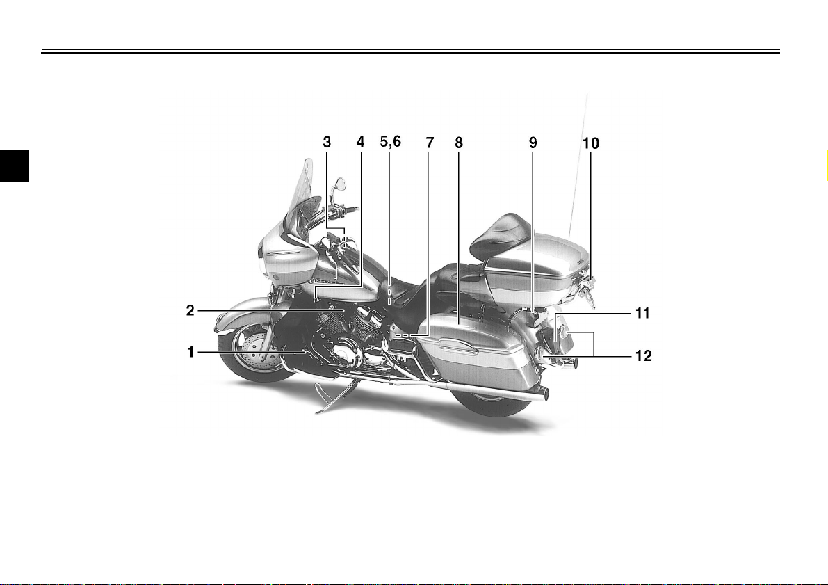
Left view
2
EAU00026
1.Shift pedal (page 3-11)
2.Starter (choke) knob (page 3-15)
3.Fuel tank cap (page 3-12)
4.Fuel cock (page 3-14)
5.Battery (page 7-29)
6.Coolant reservoir tank (page 7-14)
7.Fuse box B (page 7-31)
8.Saddlebag (page 3-17)
9.Helmet holder (page 3-16)
10.Licence light (page 7-34)
11.Tail/brake light (page 7-33)
12.Rear turn signal lights (page 7-33)
2-1
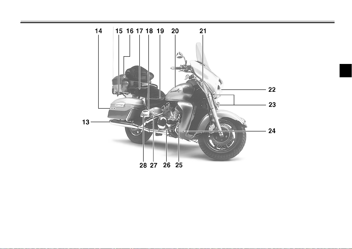
Right view
DESCRIPTION
2
13.Muffler
14.Tool kit (page 7-1)
15.Helmet holder (page 3-16)
16.Travel trunk (page 3-18)
17.Passenger seat
18.Rear shock absorber air valve (page 3-21)
19.Rider seat (page 3-15)
20.Fuel tank (page 3-12)
21.Front fork air valve (page 3-19)
22.Headlight (page 7-32)
23.Front turn signal lights (Page 7-33)
24.Fuse box A (page 7-31)
25.Rear brake pedal (page 3-11)
26.Rider footrest
27.Coolant reservoir tank (page 7-14)
28.Passenger footrest
2-2
DESCRIPTION
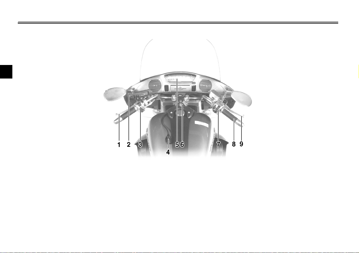
Controls/Instruments
2
1.Clutch lever (page 3-10)
2.Audio system control unit (page 4-3)
3.Left handlebar switches (page 3-9)
4.Rider headset jack (page 4-2)
5.Speedometer (page 3-5)
6.Main switch/steering lock (page 3-1)
7.Right handlebar switches (page 3-10)
8.Throttle grip (page 7-18)
9.Front brake lever (page 3-11)
2-3

INSTRUMENT AND CONTROL FUNCTIONS
Main switch/steering lock......................................3-1
Indicator lights ......................................................3-3
Speedometer........................................................3-5
Cruise control system...........................................3-7
Antitheft alarm (optional) ......................................3-8
Fuel gauge............................................................3-9
Handlebar switches . .... .........................................3-9
Clutch lever.........................................................3-10
Shift pedal...........................................................3-11
Front brak e lever.................................................3-11
Rear brake pedal................................................3-11
Fuel tank cap......................................................3-12
Fuel.................................................................... 3-13
Fuel tank breather hose..................................... 3-13
Fuel cock............................................................ 3-14
Starter (choke) knob .......................................... 3-15
Rider seat........................................................... 3-15
Helmet holders................................................... 3-16
Saddlebags and travel trunk .............................. 3-17
Front fork adjustment ......................................... 3-19
Rear shock absorber adjustment ....................... 3-21
Sidestand........................................................... 3-21
Sidestand/clutch switch operation check............ 3-22
Auxiliary DC jack and terminal........................... 3-23
3
3-
INSTRUMENT AND CONTROL FUNCTIONS
ACC (Accessory)
The audio system, auxiliary DC terminal and jack can be used in this position.
The key cannot be removed in this position. Do not use the accessory posi-
3
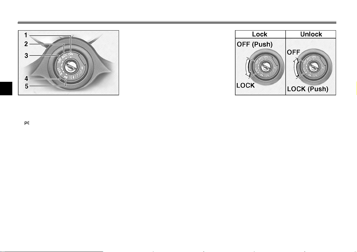
1. ON
2. ACC (Accessory)
3. OFF
4. LOCK
5. (Parking)
EAU00029*
Main switch/steering lock
tion for an extended period of time as
the battery may discharge.
OFF
All electrical circuits are switched off.
The key can be removed in this position.
The main switch controls the ignition
and lighting systems. Its operation is
described below.
EAU00036
ON
Electrical circuits are switched on. The
engine can be started. The key cannot
be removed in this position.
EAU01842
EAU00038
EAU00027
EAU00040*
LOCK
The steering is locked in this position
and all electrical circuits are switched
off. The key can be removed in this position.
To lock the steering, turn the handlebars all the way to the left. While pushing the key into the main switch, turn it
from “OFF” to “LOCK” and remove it.
To release the lock, turn the key to
“OFF” while pushing.
3-1
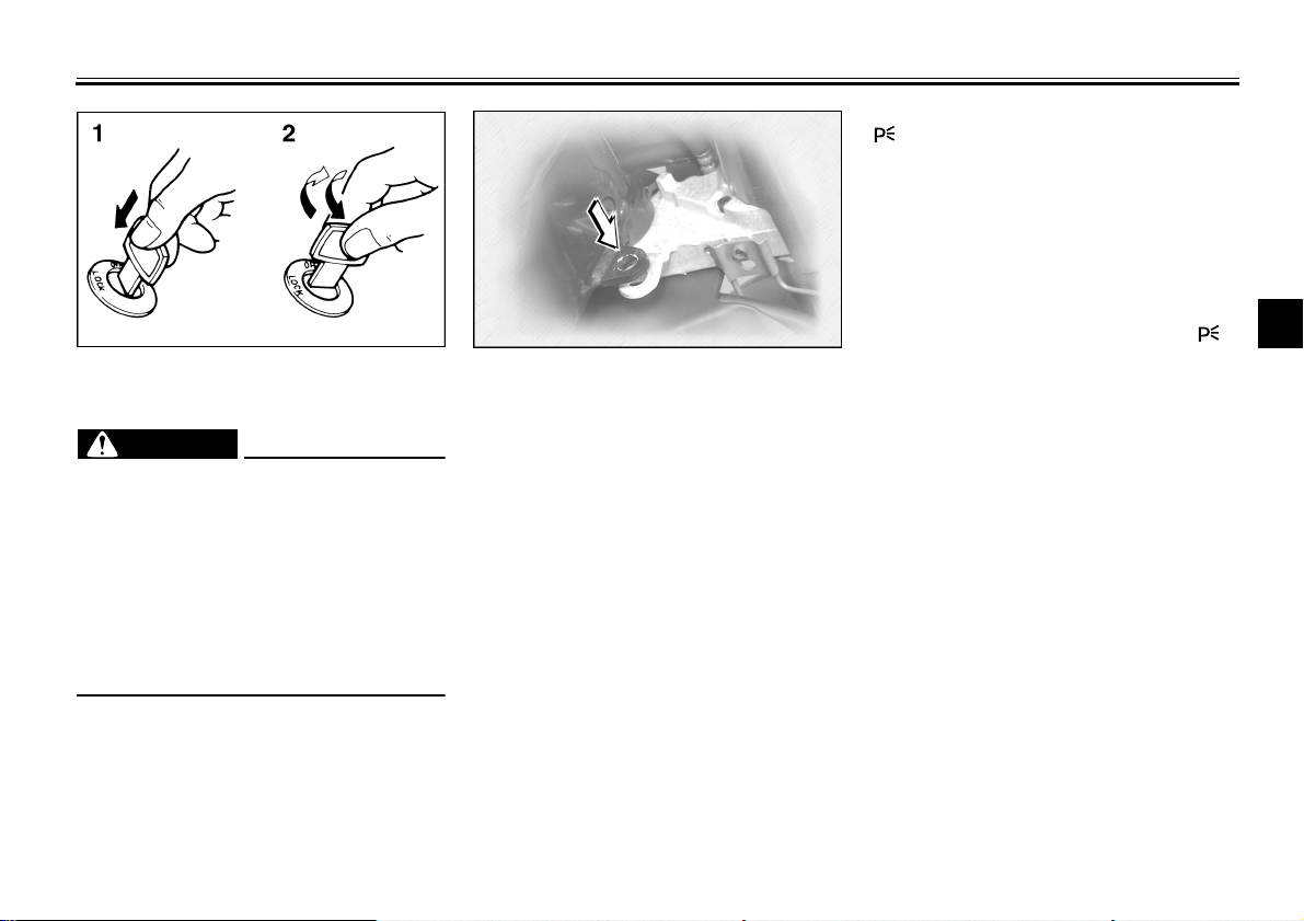
1. Push
2. Turn
EW000016
WARNING
@
Never turn the key to “OFF” or
“LOCK” when the motorcycle is
moving. The electrical circuits will
be switched off which may result in
loss of control or an accident. Be
sure the motorcycle is stopped before turning the key to “OFF” or
“LOCK”.
@
INSTRUMENT AND CONTROL FUNCTIONS
(Parking)
The steering is locked in this position,
and the taillight, license light and auxiliary light come on but all other circuits
are off. The key can be removed in this
position.
To use the parking position, first lock
the steering, then turn the key to “ ”.
Do not use this position for an extend-
On the right side of the headpipe, there
is also a place to lock the steering with
a padlock. Turn the handlebars to align
the holes in the two brackets and lock
the steering with a suitable padlock.
ed length of time as the battery may
discharge.
EAU01861
3
3-2

INSTRUMENT AND CONTROL FUNCTIONS
3
EAU00056
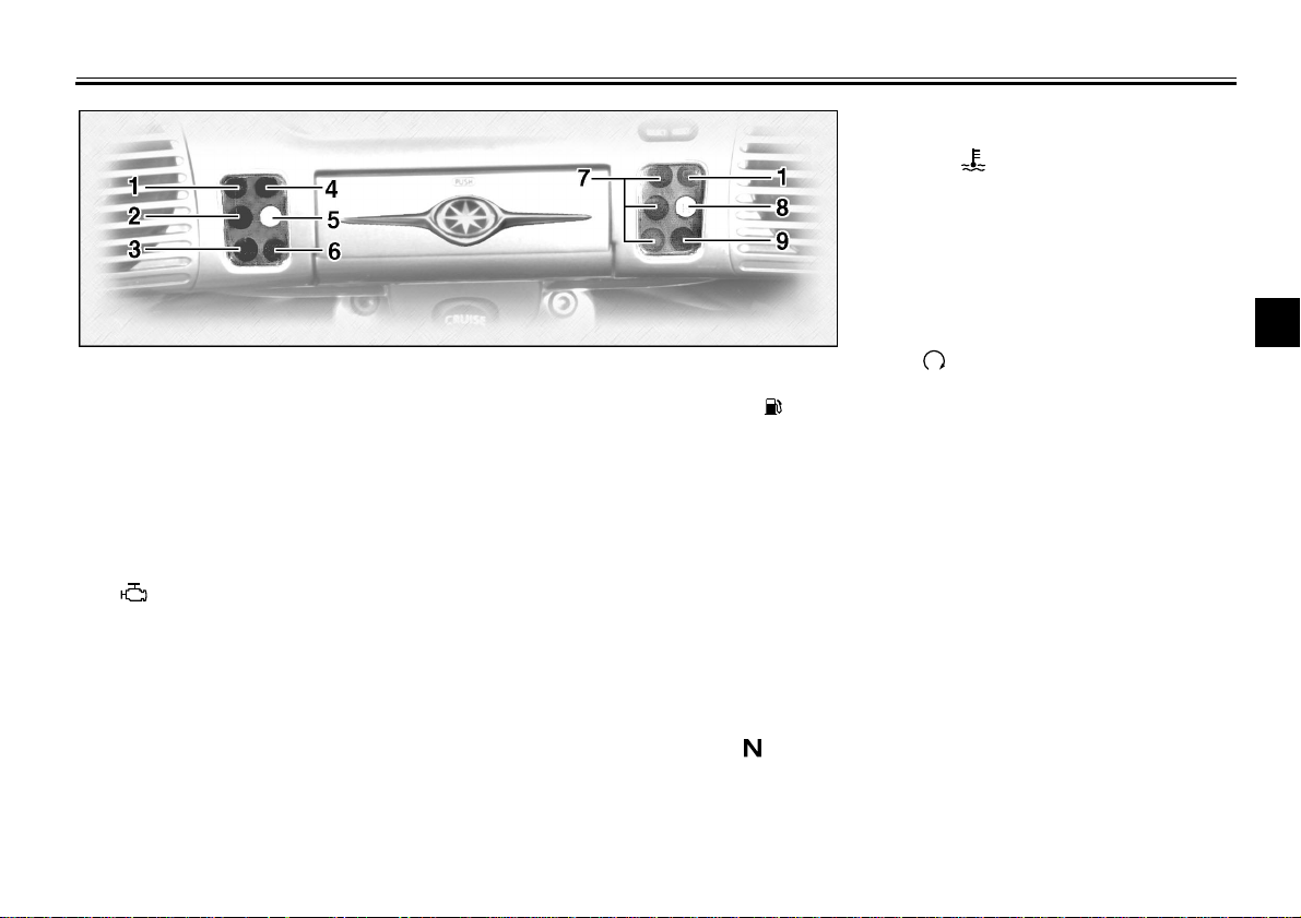
Indicator lights
EAU00058
1. Turn indicator lights “ ” / “ ”
The corresponding indicator flashes
when the turn switch is moved to the
left or right.
EAU00063
2. High beam indicator light “ ”
This indicator comes on when the
headlight high beam is used.
EAU01209
3. Oil level indicator light “ ”
This indicator light will come on if the oil
level is low. To check that the indicator
light is working properly:
Turn the engine stop switch to
●
“ ” and the main switch to “ON”.
Put the transmission in neutral or
●
apply the clutch lever.
Push the start switch.
●
If the indicator light does not come on
while pushing the start switch, have a
Yamaha dealer inspect the electrical
circuit.
NOTE:
@
Even if the oil is filled to the specified
level, the indicator light may flicker
when riding on a slope or during sudden acceleration or deceleration, but
this is normal.
@
3-3
EAU01774
4. Overdrive indicator light “O/D”
This indicator light will come on when
the transmission is in overdrive (5th
gear).
EAU00091
5. Engine trouble indicator light
“”
This indicator light will come on or flash
if trouble occurs in a monitoring circuit.
In such a case, take the motorcycle to a
Yamaha dealer to have the self-diagnostic systems checked.
INSTRUMENT AND CONTROL FUNCTIONS
9. Coolant temperature indicator
light “ ”
This indicator light will come on if the
engine overheats. If the light comes on,
stop the engine immediately and allow
the engine to cool. To check that the indicator light is working properly:
Turn the engine stop switch to
●
“ ” and the main switch to “ON”.
EAU00079
6. Fuel level indicator light “ ”
When the fuel level drops below approximately 3.5 L, this light will come
on. When this light comes on, switch
the fuel cock to “RES”. Then, fill the
tank at the first opportunity.
EAU01773
7. Cruise control indicator lights
See page 3-7 for an explanation of the
functions of these indicator lights.
EAU00061
8. Neutral indicator light “ ”
This indicator comes on when the
transmission is in neutral.
Put the transmission in neutral or
●
apply the clutch lever.
Push the start switch.
●
If the indicator light does not come on
while pushing the start switch, have a
Yamaha dealer inspect the electrical
circuit.
EAU01257*
3
3-4

INSTRUMENT AND CONTROL FUNCTIONS
NOTE:
3
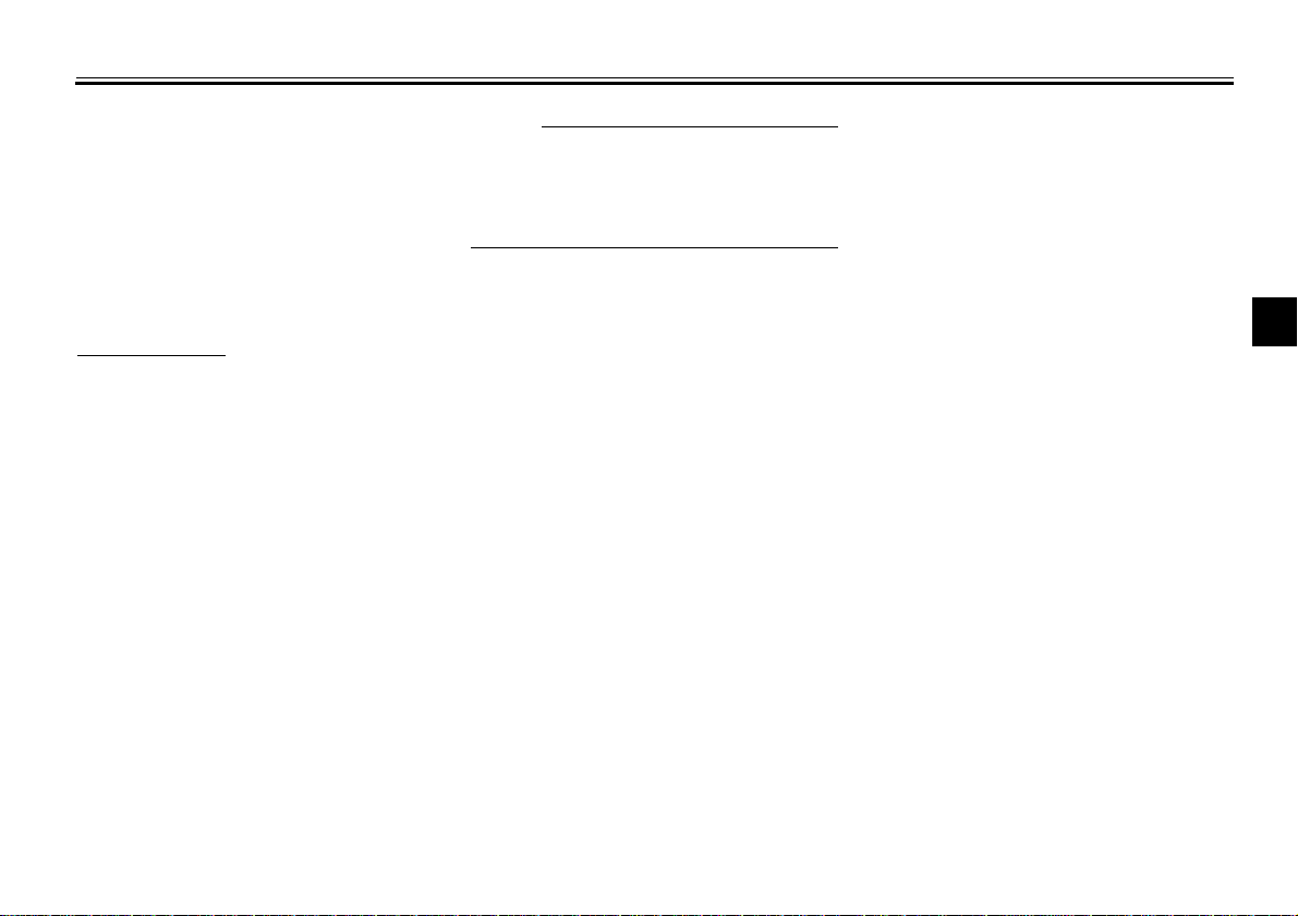
1. Speedometer
2. Odometer/tripmeter/clock
3. “RESET” button
4. “SELECT” button
Speedometer
This speedometer is equipped with:
an odometer
●
two trip odometers
●
a fuel reserve trip meter
●
a clock
●
EAU01775*
Odometer and trip meter modes
Use the trip meters to estimate how far
you can ride on a tank of fuel.
Use the fuel reserve trip meter to see
the distance traveled from when the
fuel level dropped to the reserve level.
Selecting a mode
Push the “SELECT” button to change
between the odometer mode “ODO”
and the trip odometer modes “TRIP 1”
and “TRIP 2” in the following order:
“ODO” → “TRIP 1” → “TRIP 2”
→
“ODO”
If the fuel level indicator light comes on
(see page 3-4), the odometer display
will automatically change to the fuel reserve trip meter mode “TRIP F” and
start counting the distance traveled
from that point. Push the “SELECT”
button to change between the fuel reserve trip meter, trip odometers and
odometer modes in the following order:
“TRIP F” → “TRIP 1” → “TRIP 2”
→
“ODO” → “TRIP F”
Resetting a meter
To reset a trip odometer to 0.0, select it
by pushing the “SELECT” button and
push the “RESET” button. To reset the
fuel reserve trip meter, select it by
pushing the “SELECT” button and
push the “RESET” button. The display
will return to “TRIP 1”. If you do not reset the fuel reserve trip meter manually, it will automatically reset and return
to “TRIP 1” after refueling and traveling
5 km.
@
After resetting the fuel reserve trip
meter, the display always returns to the
“TRIP 1” mode, unless a different mode
had been previously selected; in that
case, the display automatically returns
to the prior mode.
@
3-5
INSTRUMENT AND CONTROL FUNCTIONS
Clock mode
To change the display to the clock
mode, push the “SELECT” button for at
least two seconds.
To change the display back to the
odometer modes, push the “SELECT”
button.
To set the clock
1. Push both the “SELECT” and
“RESET” buttons for at least two
seconds.
2. When the hour digits start flashing,
push the “RESET” button to set
the hours.
3. Push the “SELECT” button and
the minute digits will start flashing.
4. Push the “RESET” button to set
the minutes.
5. Push the “SELECT” button to start
the clock.
NOTE:
@
After setting the clock, be sure to push
the “SELECT” button before turning the
main switch to “OFF”, otherwise the
clock will not be set.
@
3
3-6

INSTRUMENT AND CONTROL FUNCTIONS
NOTE:
3
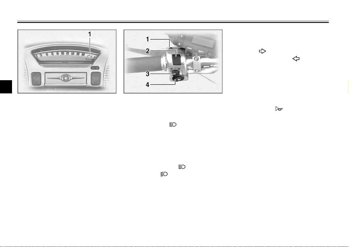
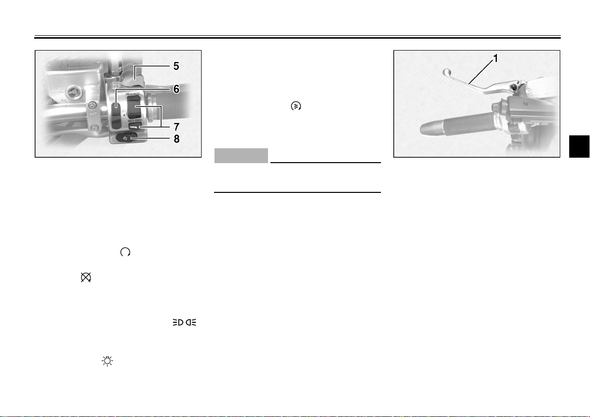
1. “CRUISE” switch 1. Cruise control switch
EAU01776
Cruise control system
This motorcycle is equipped with a
cruise control system designed to
maintain a set traveling speed.
2. “CANCEL” switch
1. Push the “CRUISE” switch to the
left to turn on the cruise control
system. The “ON” indicator light
will come on.
2. Press the “SET/DEC” (set/decel-
Activating and setting cruise control
Cruise control can only be activated
when riding in 4th or 5th gear at speeds
between 50 km/h and 130 km/h.
erate) side of the cruise control
switch to activate cruise control.
The “SET” indicator light will come
on.
3. Set the desired traveling speed as
follows. Press the “RES/ACC” (resume/accelerate) side of the
cruise control switch to increase
the set speed orthe “SET/DEC”
side to decrease the speed.
3-7
1. “SET” indicator light
2. “RES” indicator light
3. “ON” indicator light
@
Pressing the switch once will change
the speed by 1.6 km/h. Holding the
switch down will increase or decrease
the speed continuously until the switch
is released.
@
The traveling speed can be set to maximum 130 km/h and minimum 50 km/h.
When cruise control is activated and
the throttle grip is turned to increase
the traveling speed by up to 8 km/h, the
cruise control system will return to the
set speed after the throttle grip is released. However, if the speed is in-

INSTRUMENT AND CONTROL FUNCTIONS
creased by more than 8 km/h, cruise
control will be deactivated until the traveling speed returns to within 8 km/h of
the set speed.
Deactivating cruise control
Applying the front or rear brake or disengaging the clutch will automatically
deactivate cruise control.
Push the “CANCEL” switch to manually
deactivate cruise control and return to
normal throttle operation.
NOTE:
@
When cruise control is deactivat-
●
ed, the “RES” (resume) indicator
light will come on.
The traveling speed starts de-
●
creasing as soon as cruise control
is deactivated, unless the throttle
grip is turned.
@
Push the “RES/ACC” side of the cruise
control button to reactivate cruise control. The traveling speed will return to
the previously set speed. The “RES” indicator light will flash during this time
and then go off. Finally, the “SET” indicator light will come on.
Push the “CRUISE” switch to the right
to turn the cruise control system off
completely.
EWA00019
WARNING
@
If some trouble occurs in the cruise
control system, the “SET” and
“RES” indicator lights will flash simultaneously. If this occurs, turn off
the cruise control system and have
a Yamaha dealer check it.
@
EAU00109
Antitheft alarm (optional)
An antitheft alarm can be equipped to
this motorcycle. Consult your Yamaha
dealer to obtain and install the alarm.
3
3-8
INSTRUMENT AND CONTROL FUNCTIONS
3
1. Fuel gauge
EAU01779
Fuel gauge
The fuel gauge indicates the quantity of
the remaining gasoline in the tank. The
segments in the fuel gauge disappear
towards “E” (Empty) as the fuel level
decreases. When only one segment is
left near “E”, add fuel as soon as possible.
This fuel gauge is equipped with a selfdiagnosis system. If there is a problem
in an electric circuit, first the segments
and then either “E” or “F” flash. In this
case, be sure to consult a Yamaha
dealer as soon as possible.
Handlebar switches
1. Pass switch “ ”
Press the switch to operate the passing
light.
2. Dimmer switch
Turn the switch to “ ” for the high
beam and to “ ” for the low beam.
EAU00118
EAU00119
EAU00121
EAU00127
3. Turn signal switch
To signal a right-hand turn, push the
switch to “ ”. To signal a left-hand
turn, push the switch to “ ”. Once the
switch is released it will return to the
center position. To cancel the signal,
push the switch in after it has returned
to the center position.
EAU00129
4. Horn switch “ ”
Press the switch to sound the horn.
3-9
EAU00138
5. Engine stop switch
The engine stop switch is a safety device for use in an emergency such as
when the motorcycle overturns or if
trouble occurs in the throttle system.
Turn the switch to “ ” to start the engine. In case of emergency, turn the
switch to “ ” to sto p the engine.
EAU01871
6. Light switch
Turning the light switch to “ ”
turns on the auxiliary light, meter lights,
taillight and licence light. Turning the
light switch to “ ” turns the headlight
on also.
INSTRUMENT AND CONTROL FUNCTIONS
EAU01859
7. Cruise control switches
See page 3-7 for operation procedures.
EAU00143
8. Start switch “ ”
The starter motor cranks the engine
when pushing the start switch.
CAUTION:
@
See starting instructions prior to
starting the engine.
@
EC000005
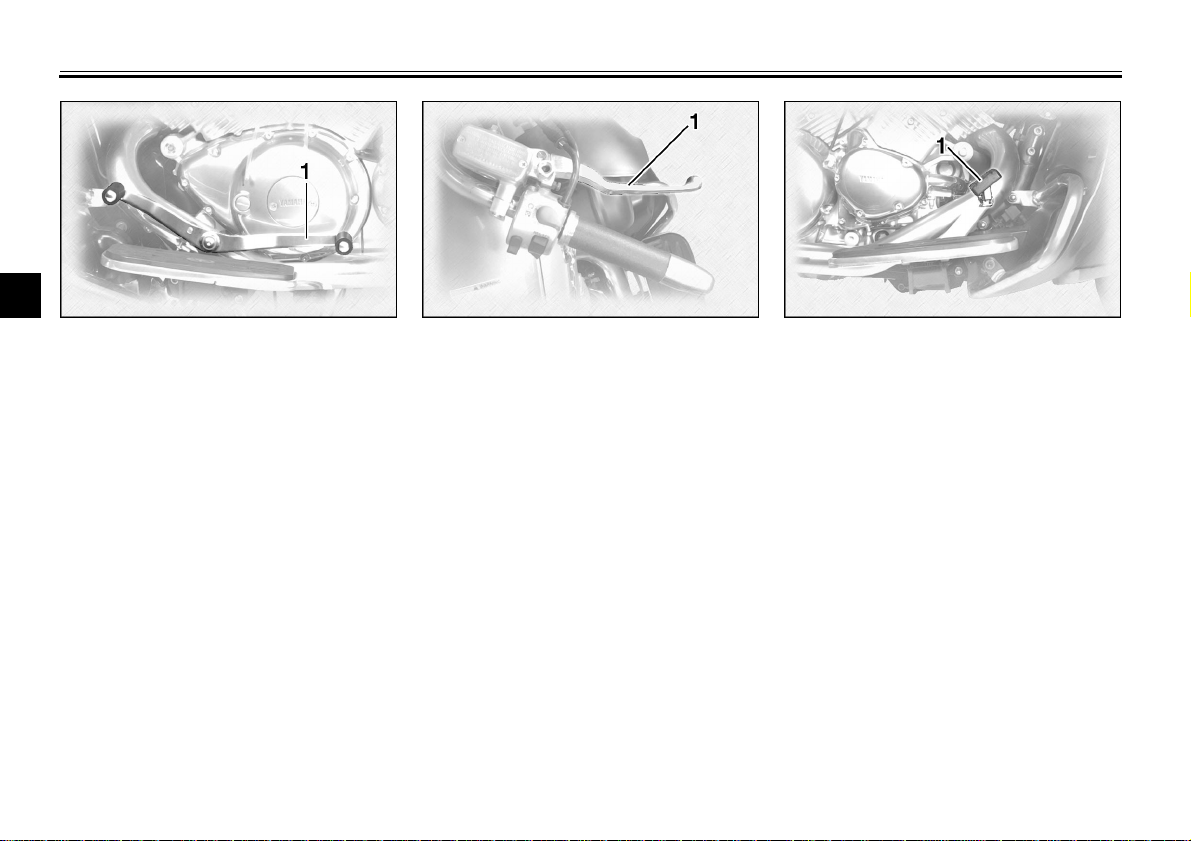
1. Clutch lever
Clutch lever
The clutch lever is located on the left
handlebar, and the ignition circuit cutoff system is incorporated in the clutch
lever holder. Pull the clutch lever to the
handlebar to disengage the clutch, and
release the lever to engage the clutch.
The lever should be pulled rapidly and
released slowly for smooth clutch operation. (Refer to the engine starting procedures for a description of the ignition
circuit cut-off system.)
3
EAU00152
3-10
INSTRUMENT AND CONTROL FUNCTIONS
3
1. Shift pedal 1. Front brake lever 1. Rear brake pedal
EAU01215
Shift pedal
The shift pedal is located on the left
side of the engine and is used in combination with the clutch when shifting.
Use your toe or heel to shift up and
your toe to shift down.
Front brake lever
The front brake lever is located on the
right handlebar. Pull it toward the handlebar to apply the front brake.
EAU00158
Rear brake pedal
The rear brake pedal is on the right
side of the motorcycle. Press down on
the brake pedal to apply the rear brake.
EAU00162
3-11
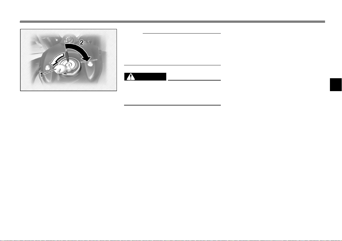
1. Lock cover
2. Open
EAU02917
Fuel tank cap
To remove
Slide the lock cover open, insert the
key and turn it 1/4 turn clockwise. The
lock will be released and the cap can
be removed.
To install
Make sure the arrow mark on the tank
cap is facing forward, then push the
tank cap into position. Turn the key
counterclockwise to the original position and remove it. Close the lock cover.
INSTRUMENT AND CONTROL FUNCTIONS
NOTE:
@
This tank cap cannot be closed unless
the key is in the lock. The key cannot
be removed if the cap is not locked
properly.
@
WARNING
@
Be sure the cap is properly installed
and locked in place before riding the
motorcycle.
@
EW000023
3
3-12

INSTRUMENT AND CONTROL FUNCTIONS
CAUTION:
@
Always wipe off spilled fuel immediately with a dry and clean soft cloth.
Fuel may deteriorate painted surfaces or plastic parts.
@
3
1. Filler tube
2. Fuel level
EAU01183
Fuel
Make sure there is sufficient fuel in the
tank. Fill the fuel tank to the bottom of
the filler tube as shown in the illustration.
WARNING
@
Do not overfill the fuel tank. Avoid
spilling fuel on the hot engine. Do
not fill the fuel tank above the bottom of the filler tube or it may overflow when the fuel heats up later and
expands.
@
EW000130
Recommended fuel:
Regular unleaded gasoline with a
research octane number of 91 or
higher.
Fuel tank capacity:
Total:
22.5 L
Reserve:
3.5 L
NOTE:
@
If knocking or pinging occurs, use a different brand of gasoline or higher octane grade.
@
EAU00185
EAU00191
1. Fuel tank breather hose
EAU02955
Fuel tank breather hose
This model is equipped with a fuel tank
breather hose.
Before using this motorcycle:
Check the hose connection.
●
Check the hose for cracks or dam-
●
age and replace it if damaged.
Make sure the end of the hose is
●
not blocked and clean it if necessary.
3-13
INSTRUMENT AND CONTROL FUNCTIONS
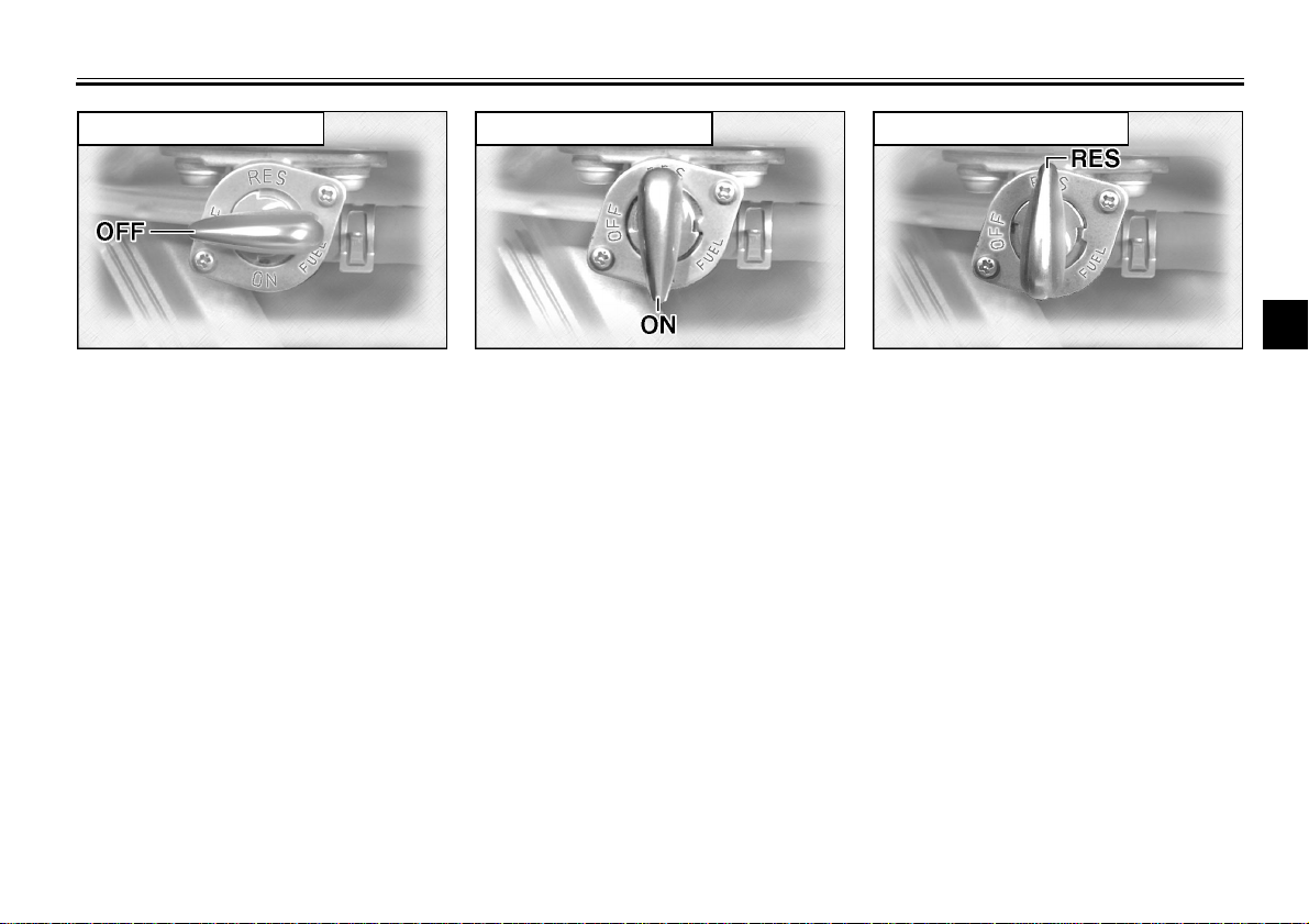
RES: reserve position
OFF: closed position ON: normal position
3
Fuel cock
The fuel cock supplies fuel from the
tank to the carburetors while filtering it
also.
The fuel cock has three positions,
which should be set as shown in the illustrations.
OFF
With the fuel cock in this position, fuel
will not flow. Always set the fuel cock to
this position when the engine is not
running.
EAU02969
ON
With the fuel cock in this position, fuel
flows to the carburetors. Set the fuel
cock to this position when starting the
engine and while riding.
3-14
RES
This indicates reserve. If you run out of
fuel while riding, set the fuel cock to this
position. Fill the tank at the first opportunity. Be sure to set the fuel cock back
to “ON” after refueling!
INSTRUMENT AND CONTROL FUNCTIONS
NOTE:
3
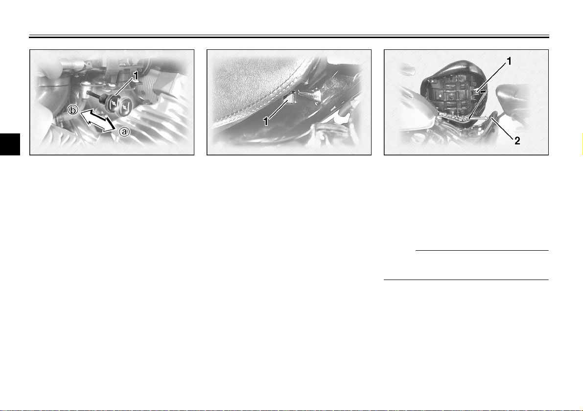
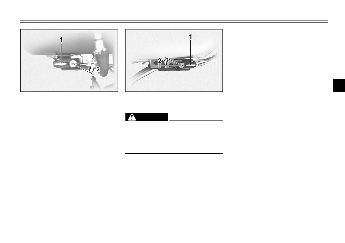
1. Starter (choke) knob 1. Nut (× 2) 1. Projection
EAU03032
Starter (choke) knob
Starting a cold engine requires a richer
air-fuel mixture, which is supplied by
the starter (choke).
Rider seat
To remove
Remove the nuts and lift up the rider
seat.
EAU01781
2. Seat holder
To install
Insert the projection on the rear of the
rider seat into the seat holder, then
tighten the nuts.
Move the knob in direction a to turn on
the starter (choke).
Move the knob in direction b to turn off
the starter (choke).
3-15
@
Make sure that the rider seat is securely fitted.
@
INSTRUMENT AND CONTROL FUNCTIONS
3
1. Helmet holder (right)
2. Open
EAU01782
Helmet holders
To open a helmet holder, insert the key
in the lock and turn it as shown. To lock
the helmet holder, place the holder in
its original position and remove the
key.
1. Helmet holder (left)
2. Open
EWA00015
WARNING
@
Never ride with a helmet in either
helmet holder. The helmet may hit
objects, causing loss of control and
possibly an accident.
@
3-16
 Loading...