

Yamaha XT250, XT250XC, XT250X Owner's Manual

XT250XC
OWNER’S MANUAL
XT250X
EAU10041

INTRODUCTION
EAU10080
EAU10131
EWA10010

IMPORTANT MANUAL INFORMATION
EAU10192
XT250X/XT250XC
OWNER’S MANUAL
1st edition, June 2007
All rights reserved.
Printed in Japan.
P/N LIT-11626-21-52
AFFIX DEALER
LABEL HERE

.................................. 5-1
............................................... 6-1
Tires .............................................. 6-19
Spoke wheels ............................... 6-21
Accessories and replacement
parts ........................................... 6-22
Adjusting the clutch lever free
play ............................................ 6-22
Adjusting the brake lever free
play ............................................ 6-23
Adjusting the rear brake light
switch ......................................... 6-24
Checking the front and rear brake
pads ........................................... 6-24
Checking the brake fluid level ....... 6-25
Changing the brake fluid ............... 6-26
Drive chain slack ........................... 6-26
Cleaning and lubricating the drive
chain .......................................... 6-27
Checking and lubricating the
cables ........................................ 6-28
Checking and lubricating the throttle
grip and cable ............................ 6-28
Checking and lubricating the brake
and shift pedals ......................... 6-28
Checking and lubricating the brake
and clutch levers ........................ 6-29
Checking and lubricating the
sidestand ................................... 6-30
Lubricating the rear suspension .... 6-30
Checking the front fork .................. 6-30
Checking the steering ................... 6-31
Checking the wheel bearings ........ 6-32
TABLE OF CONTENTS

1-1
motorist’s blind spot.
●
Many accidents involve inexperienced operators. In fact, many operators who have been involved in
accidents do not even have a current motorcycle license.
●
Make sure that you are qualified
and that you only lend your motorcycle to other qualified operators.
●
Know your skills and limits.
Staying within your limits may
help you to avoid an accident.
●
We recommend that you practice riding your motorcycle
where there is no traffic until you
have become thoroughly familiar with the motorcycle and all of
its controls.
●
Many accidents have been caused
by error of the motorcycle operator. A typical error made by the operator is veering wide on a turn
due to EXCESSIVE SPEED or undercornering (insufficient lean angle for the speed).
●
Always obey the speed limit and
never travel faster than warrant-
SAFETY INFORMATION
1-2
1
der the motorcycle unsafe for use and
may cause severe personal injury.
Modifications may also make your motorcycle illegal to use.
Loading and accessories
Adding accessories or cargo to your
motorcycle can adversely affect stability and handling if the weight distribution
of the motorcycle is changed. To avoid
the possibility of an accident, use extreme caution when adding cargo or
accessories to your motorcycle. Use
extra care when riding a motorcycle
that has added cargo or accessories.
Here are some general guidelines to
follow if loading cargo or adding accessories to your motorcycle:
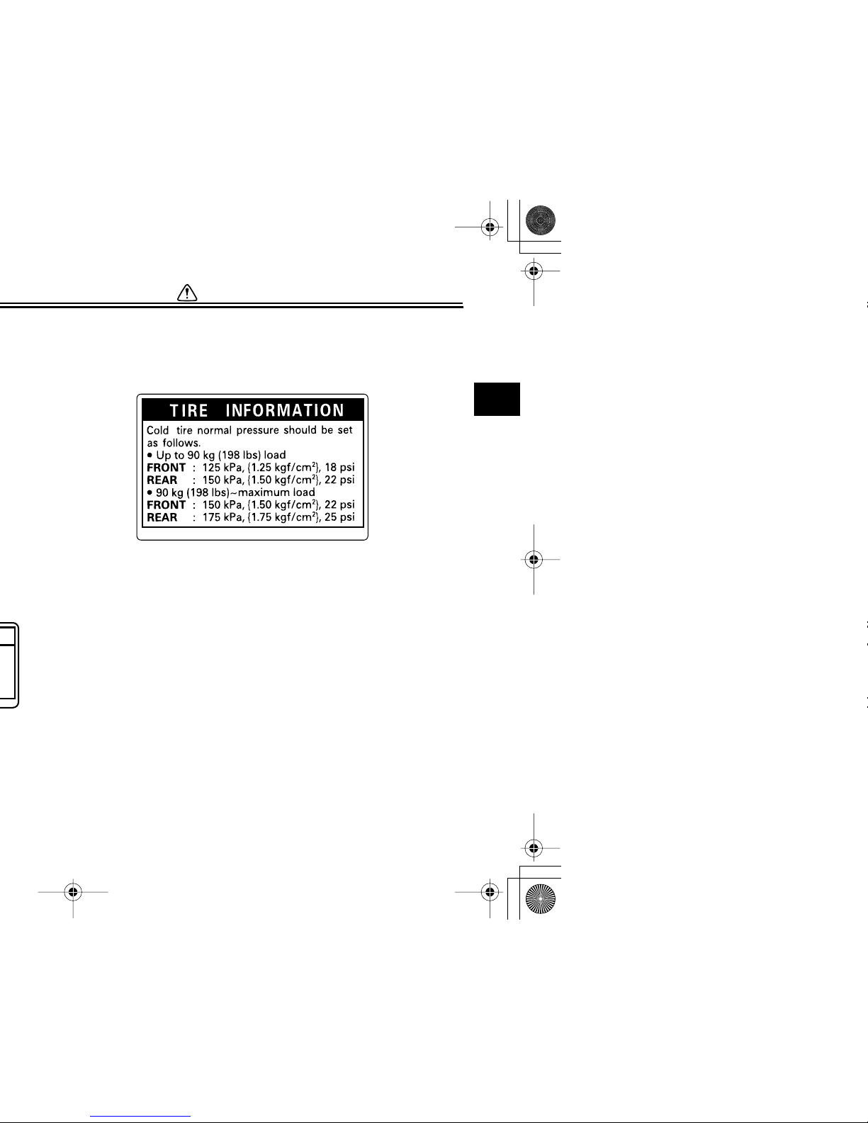
Loading
The total weight of the operator, passenger, accessories and cargo must
not exceed the maximum load limit.
When loading within this weight limit,
keep the following in mind:
Maximum load:
160 kg (353 lb)

1-3
the motorcycle due to aerodynamic effects. Wind may attempt to lift the motorcycle, or
the motorcycle may become unstable in cross winds. These accessories may also cause
instability when passing or being
passed by large vehicles.
●
Certain accessories can displace the operator from his or
her normal riding position. This
improper position limits the freedom of movement of the operator and may limit control ability,
therefore, such accessories are
not recommended.
●
Use caution when adding electrical accessories. If electrical accessories exceed the capacity of the
motorcycle’s electrical system, an
electric failure could result, which
could cause a dangerous loss of
lights or engine power.
Gasoline and exhaust gas
●
GASOLINE IS HIGHLY FLAMMABLE:
●
Always turn the engine off when

SAFETY INFORMATION
1-4
1
1-5
EAU10381
21 3
SAFETY INFORMATION
1-6
1
3
3TT-21668-00
1-7
2

SAFETY INFORMATION
1-8
1
2-1
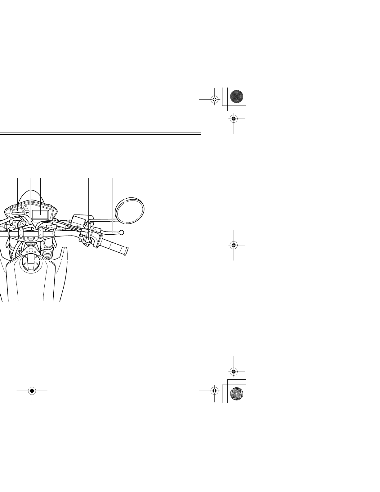
EAU10410
1 2 43
DESCRIPTION
2-2
2
3
4
5
6
7
8
9
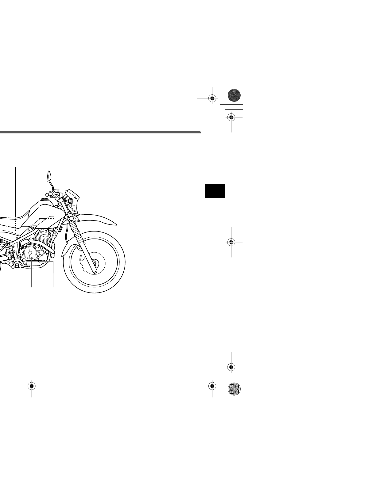
EAU10420
23 4
5
6
2-3
EAU10430
9
4
9. Fuel tank cap (page 3-6)

3-1
2
3
4
5
6
7
8
9
EAU10660
EAU10690
2. Push the key in from the “OFF” position, and then turn it to “LOCK”
while still pushing it.
3. Remove the key.
To unlock the steering
Push the key into the main switch, and
then turn it to “OFF” while still pushing
it.
WARNING
EWA10060
Never turn the key to “OFF” or
“LOCK” while the vehicle is moving,
otherwise the electrical systems will
be switched off, which may result in
loss of control or an accident. Make
1
2
1. Push.
2. Turn.
1
2
3-2
EAU10980
EAU11020
EAU11060
EAU11080
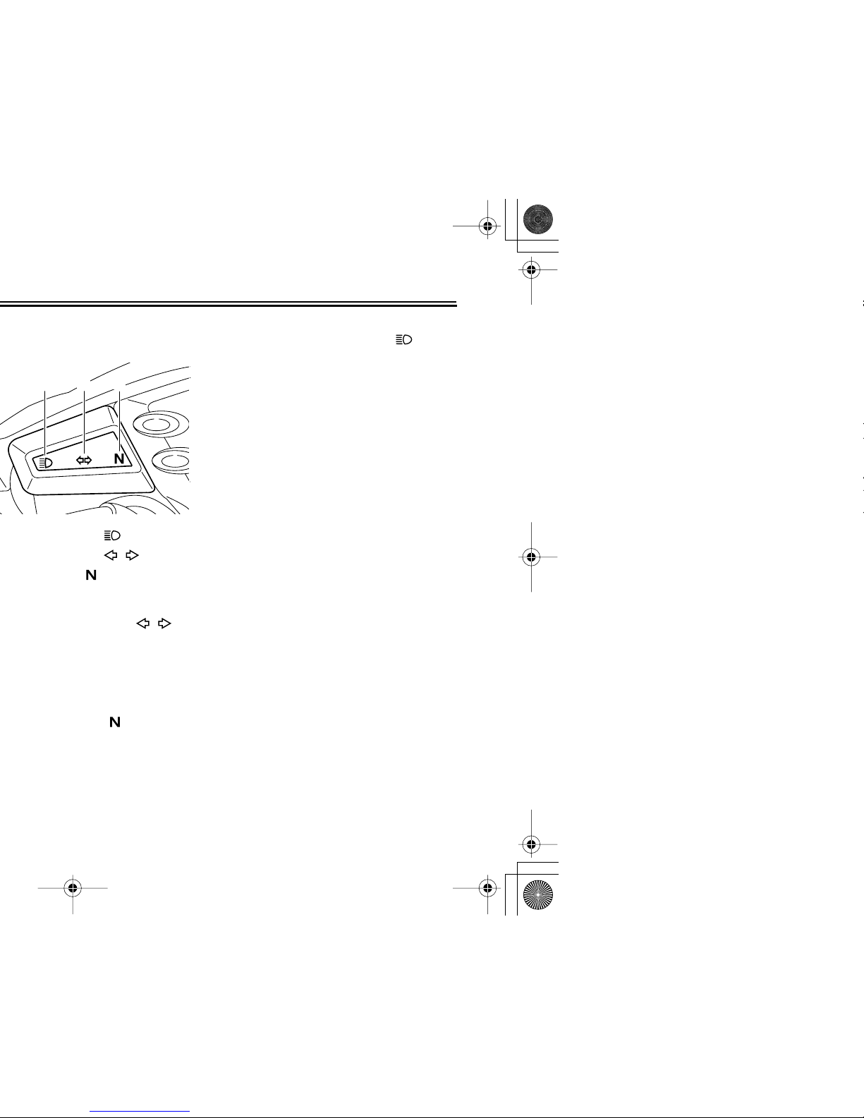
High beam indicator light “”
This indicator light comes on when the
high beam of the headlight is switched
on.
1 2
3
3-3
2
3
4
5
6
7
8
9
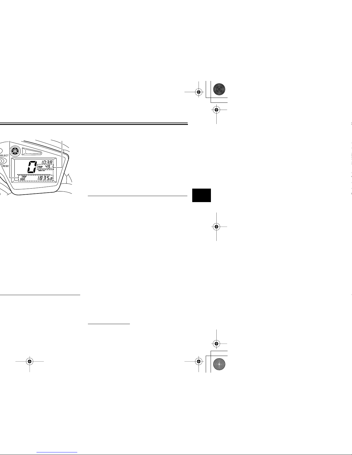
multi-function display will appear
one after the other and then disappear, in order to test the electrical
circuit.
●
To switch the speedometer and
odometer/tripmeter displays between miles and kilometers, press
the “SELECT” button for at least
two seconds.
Odometer, clock and tripmeter
modes
Pushing the “SELECT” button switches
the display between the odometer
mode “ODO” and the tripmeter modes
“TRIP” in the following order:
ODO → TRIP (top) → TRIP (bottom) →
ODO
To reset a tripmeter, select it by pushing the “SELECT” button until “TRIP”
begins flashing (“TRIP” will only flash
for five seconds). While “TRIP” is flashing, push the “RESET” button for at
least one second.
Clock mode
To set the clock:
1. Push the “SELECT” button and
2
1
3-4
EAU12347
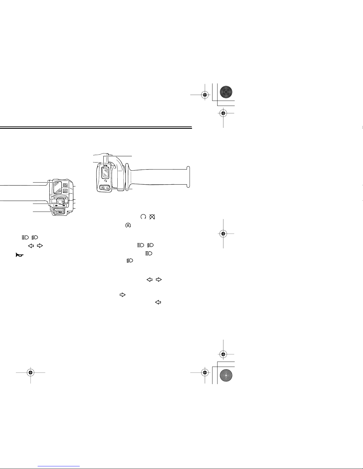
Right
EAU12400
Dimmer switch “ / ”
Set this switch to “” for the high
beam and to “” for the low beam.
EAU12460
Turn signal switch “ / ”
To signal a right-hand turn, push this
switch to “”. To signal a left-hand
turn, push this switch to “”. When re-
leased, the switch returns to the center
position. To cancel the turn signal
lights, push the switch in after it has returned to the center position.
1
2
3
1. Engine stop switch “ / ”
2. Start switch “”
1
2

3-5
2
3
4
5
6
7
8
9
EAU12820
EAU12870
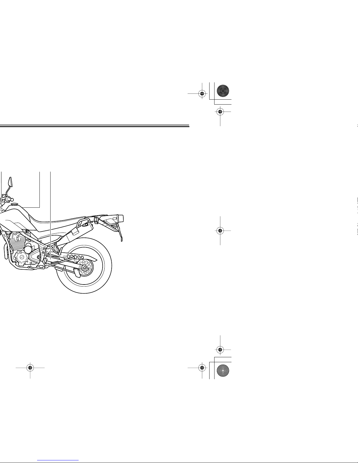
Shift pedal
The shift pedal is located on the left
side of the engine and is used in combination with the clutch lever when
shifting the gears of the 5-speed constant-mesh transmission equipped on
this motorcycle.
1
1. Shift pedal
1
3-6
EAU12941
EAUM1792
Fuel tank cap
To remove the fuel tank cap
1. Open the fuel tank cap lock cover.
2. Insert the key into the lock and turn
it 1/4 turn clockwise. The lock will
be released and the fuel tank cap
can be removed.
To install the fuel tank cap
1. Push and install the fuel tank cap
into position with the key inserted
in the lock.
2. Turn the key counterclockwise to
the original position, and then remove it.
1
1. Fuel tank cap lock cover
2. Unlock.
1
2
3-7
2
3
4
5
6
7
8
9
EAU13211
EWA10880
ECA10070
fuel may deteriorate painted surfaces or plastic parts.
EAU13300
CAUTION:
ECA11400
Use only unleaded gasoline. The use
of leaded gasoline will cause severe
damage to internal engine parts,
such as the valves and piston rings,
as well as to the exhaust system.
Your Yamaha engine has been designed to use regular unleaded gasoline with a pump octane number
[(R+M)/2] of 86 or higher, or a research
octane number of 91 or higher. If
knocking (or pinging) occurs, use a
gasoline of a different brand or premi-
Recommended fuel:
UNLEADED GASOLINE ONLY
Fuel tank capacity:
9.1 L (2.40 US gal) (2.00 Imp.gal)
(CAL)
9.8 L (2.59 US gal) (2.16 Imp.gal)
(U49)
Fuel reserve amount:
1.9 L (0.50 US gal) (0.42 Imp.gal)
3-8
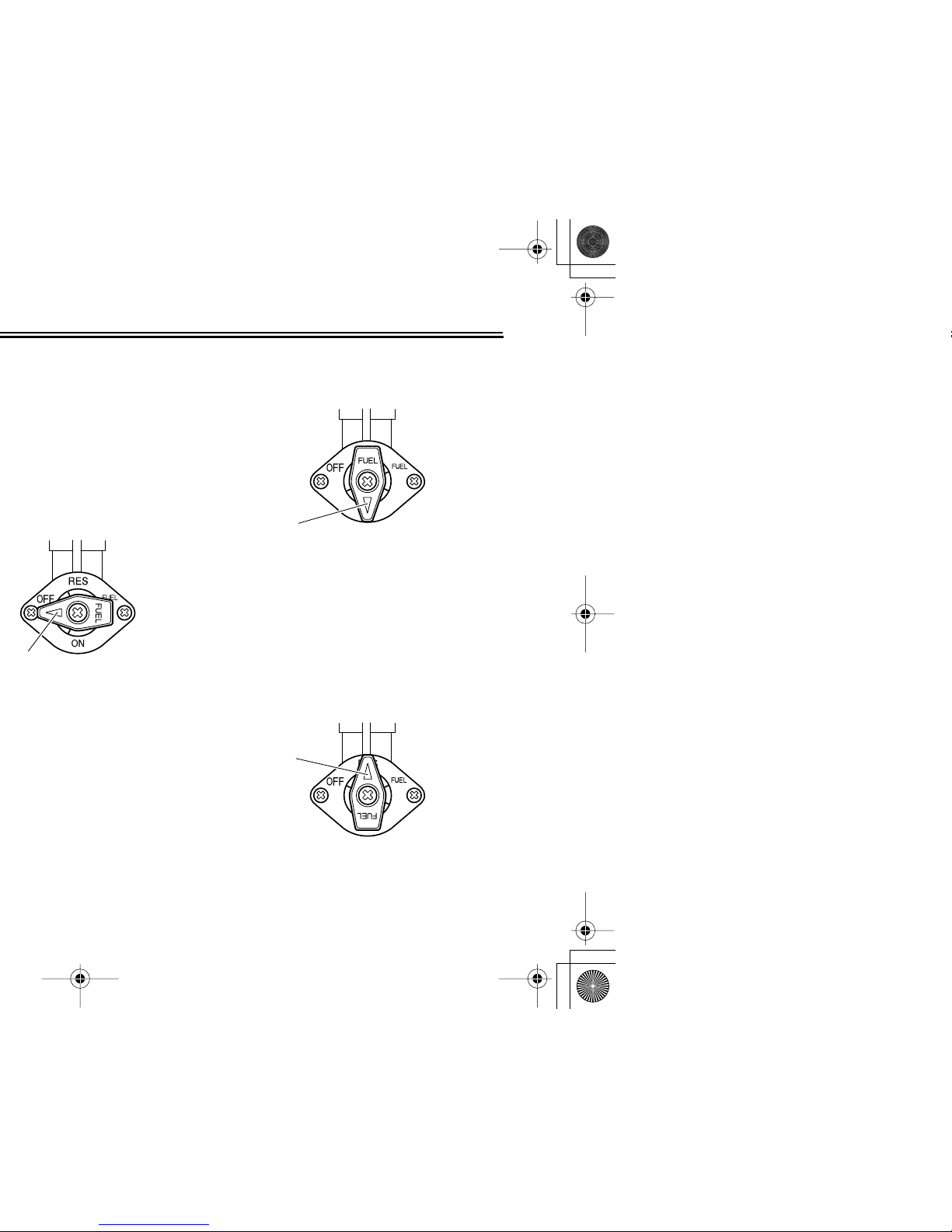
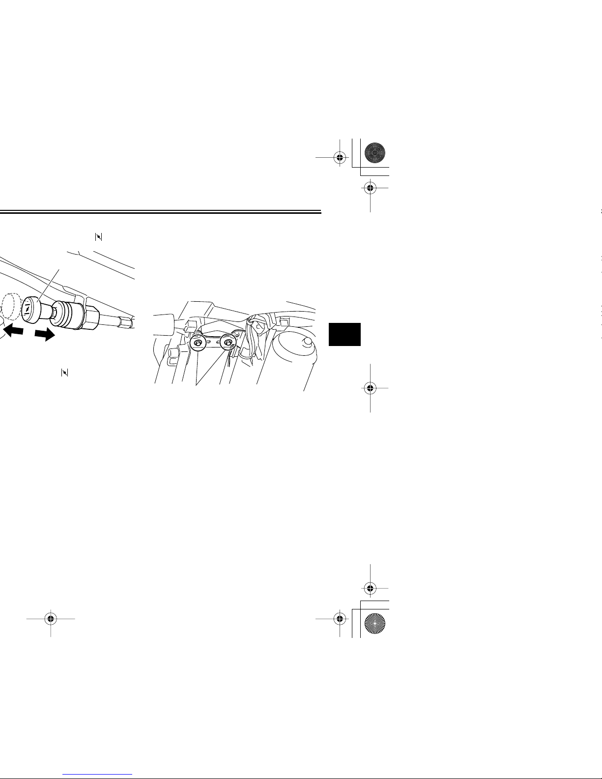
EAU13561
ON
With the lever in this position, fuel flows
to the carburetor. Normal riding is done
with the lever in this position.
RES
1
1. Pointed end positioned over “ON”
1. Pointed end positioned over “RES”
1
1
3-9
2
3
4
5
6
7
8
9
EAU13600
EAU13970
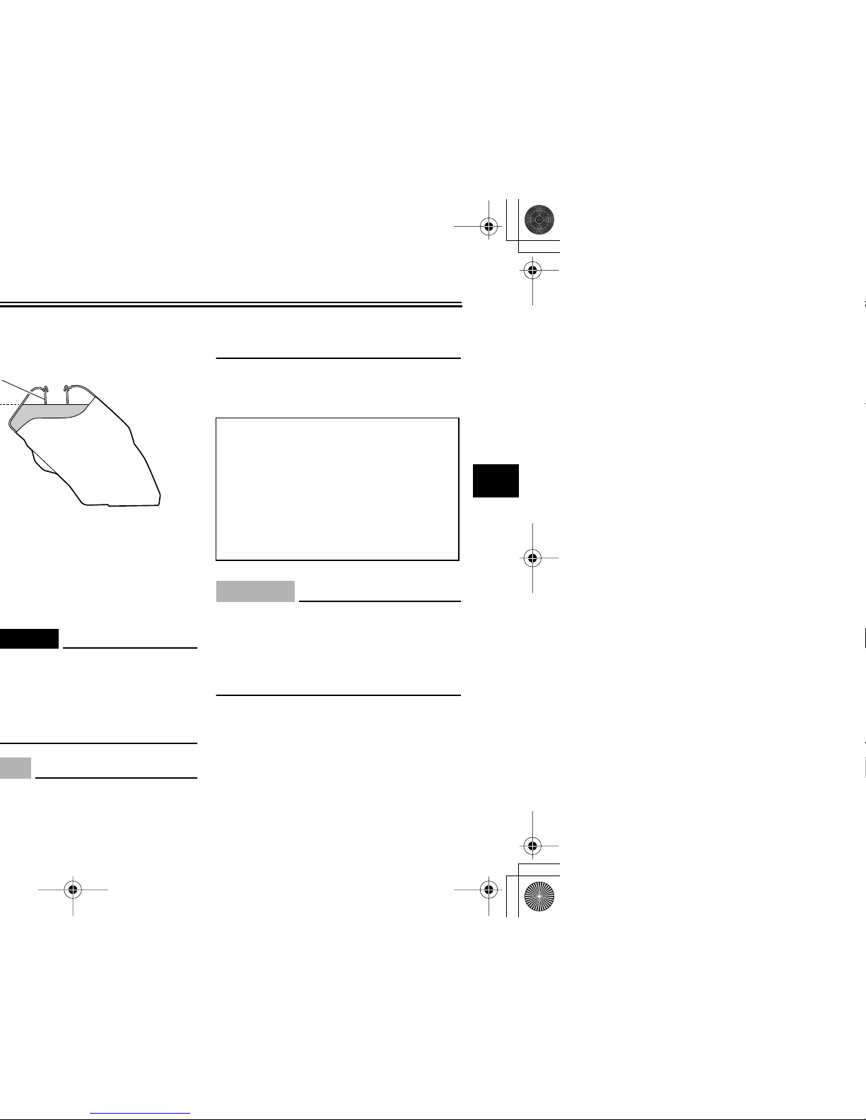
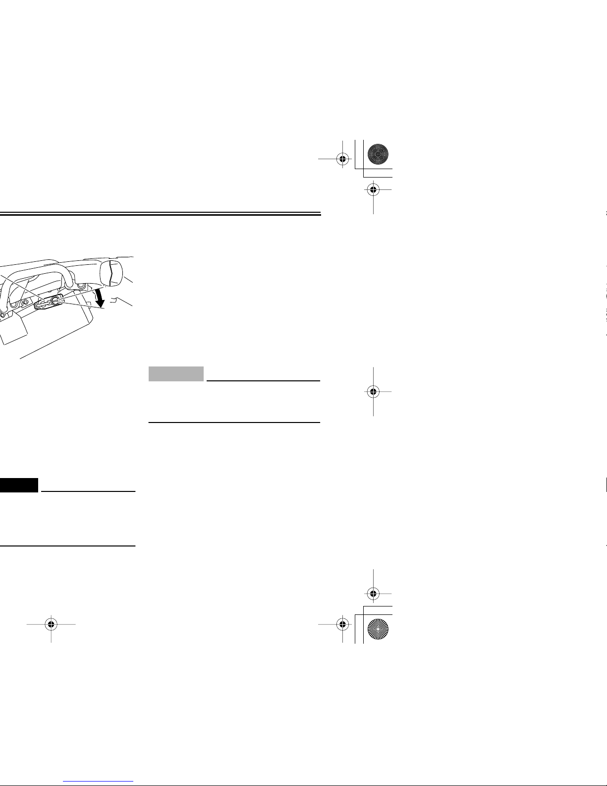
Seat
To remove the seat
Remove the bolts, and then pull the
seat off.
To install the seat
1. Insert the projection on the front of
the seat into the seat holder as
shown.
1
(a)
(b)
1. Bolt
1
3-10
EAU14281
EWA10160
EAU44770
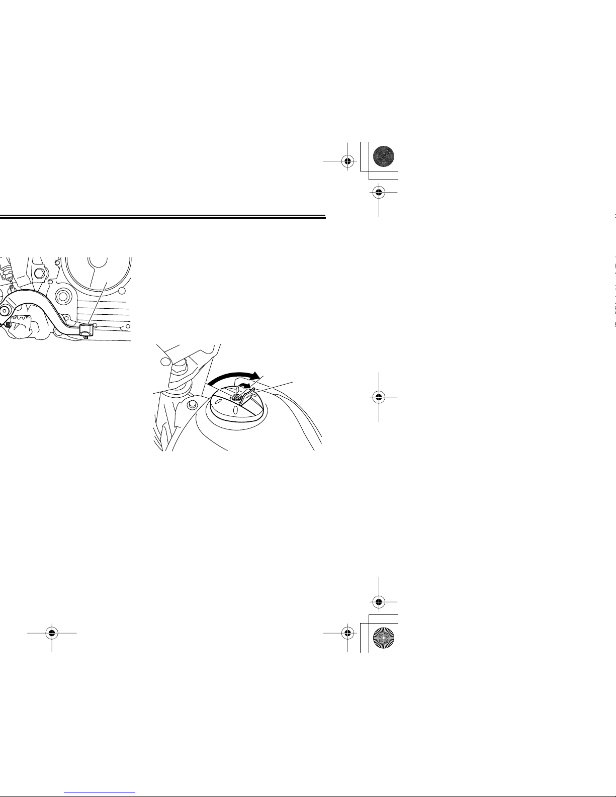
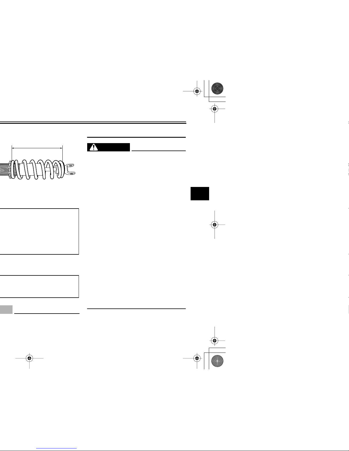
Adjusting the shock absorber
assembly
This shock absorber assembly is
equipped with a spring preload adjusting ring.
It is recommended to have a Yamaha
dealer adjust the spring preload. However, if you choose to make this adjustment yourself, obtain a special wrench
at a Yamaha dealer.
CAUTION:
ECA10100
Never attempt to turn an adjusting
mechanism beyond the maximum or
minimum settings.
1. Loosen the locknut.
2. To increase the spring preload and
thereby harden the suspension,
turn the adjusting ring in direction
(a). To decrease the spring preload and thereby soften the suspension, turn the adjusting ring in
direction (b).
2
3-11
2
3
4
5
6
7
8
9
ECA10130
the locknut to the specified torque.
WARNING
EWA10220
This shock absorber contains highly
pressurized nitrogen gas. For proper handling, read and understand
the following information before
handling the shock absorber. The
manufacturer cannot be held responsible for property damage or
personal injury that may result from
improper handling.
●
Do not tamper with or attempt to
open the gas cylinder.
●
Do not subject the shock absorber to an open flame or other
high heat sources, otherwise it
may explode due to excessive
gas pressure.
●
Do not deform or damage the
gas cylinder in any way, as this
will result in poor damping performance.
●
Always have a Yamaha dealer
service the shock absorber.
1
3-12
EAU15312
Ignition circuit cut-off system
The ignition circuit cut-off system (comprising the sidestand switch, clutch
switch and neutral switch) has the following functions.
●
It prevents starting when the transmission is in gear and the sidestand is up, but the clutch lever is
not pulled.
●
It prevents starting when the transmission is in gear and the clutch lever is pulled, but the sidestand is
still down.
●
It cuts the running engine when the
transmission is in gear and the sidestand is moved down.
Periodically check the operation of the
ignition circuit cut-off system according
to the following procedure.
WARNING
EWA10250
If a malfunction is noted, have a
Yamaha dealer check the system before riding.
 Loading...