


XQ125
2001
XQ150
5HT1-AE2
SERVICE MANUAL

EASM0000
XQ125 / XQ150
SERVICE MANUAL
© 2001 by MBK Industrie
2nd edition, April 2001
All rights reserved.
Any reproduction or unauthorized
use without the written
permission of MBK Industrie
is expressly prohibited.

EAS00005
IMPORTANT MANUAL INFORMATION
Particularly important information is distinguished in this manual by the following.
The Safety Alert Symbol means ATTENTION! BECOME ALERT! YOUR SAFETY
IS INVOLVED!
Failure to follow WARNING instructions
could result in severe injury or death to
the scooter operator, a bystander or a person checking or repairing the scooter.
A CAUTION indicates special precautions that must be taken to avoid damage
to the scooter.
A NOTE provides key information to make procedures easier or clearer.
NOTE:
WARNING
CAUTION:
EASM0001
NOTICE
This manual was produced by the MBK Industrie primarily for use by Yamaha and MBK dealers and
their qualified mechanics. It is not possible to include all the knowledge of a mechanic in one manual.
Therefore, anyone who uses this book to perform maintenance and repairs on Yamaha and MBK
vehicles should have a basic understanding of mechanics and the techniques to repair these types
of vehicles. Repair and maintenance work attempted by anyone without this knowledge is likely to
render the vehicle unsafe and unfit for use.
MBK Industrie is continually striving to improve all of its models. Modifications and significant changes in specifications or procedures will be forwarded to all authorized Yamaha and MBK dealers and
will appear in future editions of this manual where applicable.
NOTE:
Designs and specifications are subject to change without notice.
TECHNICAL DOCUMENTATION
MBK INDUSTRIE

EAS00007
HOW TO USE THIS MANUAL
This manual is intended as a handy, easy-to-read reference book for the mechanic. Comprehensive
explanations of all installation, removal, disassembly, assembly, repair and check procedures are
laid out with the individual steps in sequential order.
햲 The manual is divided into chapters. An abbreviation and symbol in the upper right corner of each
page indicate the current chapter. Refer to "SYMBOLS".
햳 Each chapter is divided into sections. The current section title is shown at the top of each page,
except in Chapter 3 ("PERIODIC CHECKS AND ADJUSTMENTS"), where the sub-section title(s)
appears.
햴 Sub-section titles appear in smaller print than the section title.
햵 To help identify parts and clarify procedure steps, there are exploded diagrams at the start of each
removal and disassembly section.
햶 Numbers are given in the order of the jobs in the exploded diagram. A circled number indicates
a disassembly step.
햷 Symbols indicate parts to be lubricated or replaced. Refer to "SYMBOLS".
햸 A job instruction chart accompanies the exploded diagram, providing the order of jobs, names of
parts, notes in jobs, etc.
햹 Jobs requiring more information (such as special tools and technical data) are described
sequentially.
ENG
ENG
EASM0025
CYLINDER AND PISTON
Removing the cylinder and piston
Remove the parts in the order listed.
Cylinder head
Refer to “CYLINDER HEAD” section.
1 Cylinder bolt
2
2 Timing chain guide (exhaust side)
1
3 Cylinder
1
4 Dowel pin
2
5 Cylinder gasket
1
6 Piston pin clip
2
7 Piston pin
1
8 Piston
1
9 Piston ring (top)
1
10 Piston ring (2nd)
1
11 Oil ring
1
For installation, reverse the removal
procedure.
EAS00253
REMOVING THE CYLINDER AND PISTON
1. Remove:
•piston pin clip 햲
•piston pin 햳
•piston 햴
CAUTION:
Do not use a hammer to drive the piston pin
out.
NOTE:
•Before removing the piston pin clip, cover the
crankcase opening with a clean rag to prevent
the piston pin clip from falling into the crankcase.
• Before removing the piston pin, deburr the
piston pin clip’s groove and the piston’s pin
bore area. If both areas are deburred and the
piston pin is still difficult to remove, remove it
with the piston pin puller.
Piston pin puller
90890-01304
2. Remove:
•top ring
•2nd ring
•oil ring
NOTE:
When removing a piston ring, open the end gap
with your fingers and lift the other side of the ring
over the piston crown.
EAS00255
CHECKING THE CYLINDER AND PISTON
1. Check:
•piston wall
•cylinder wall
Vertical scratches → Rebore or replace the
cylinder, and replace the piston and piston
rings as a set.
4 - 23 4 - 24
CYLINDER AND PISTON CYLINDER AND PISTON
Order Job/Part
Q’ty Remarks
햲
햳
햴
FWD
1
2
3
4
5
6
7
8
9
10
11
T
.R
12 Nm (1.2 m•kg)
햲
햹
햳햴햵
햶
햷
햸
COOL
GEN
INFO
ENG
SPEC
햲햳
햵햴
햶
햷
햸햹
햺햻
햽
햾
햿헀
헁헂
헅
쎻
22
쎻
23
헄헆
쎻
21
쎻
24
쎻
25
EAS00008
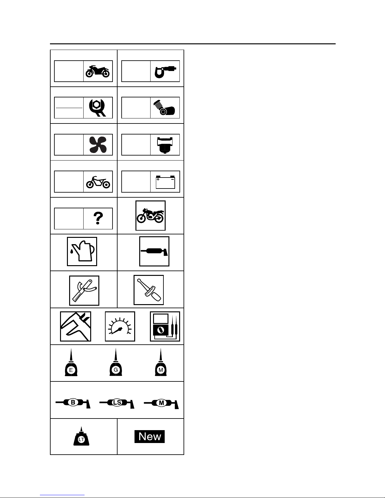
SYMBOLS
The following symbols are not relevant to every
vehicle.
Symbols
햲 to 햺 indicate the subject of each
chapter.
햲 General information
햳 Specifications
햴 Periodic checks and adjustments
햵 Engine
햶 Cooling system
햷 Carburetor
햸 Chassis
햹 Electrical system
햺 Troubleshooting
Symbols
햻 to 헃 indicate the following.
햻 Serviceable with engine mounted
햽 Filling fluid
햾 Lubricant
햿 Special tool
헀 Tightening torque
헁 Wear limit, clearance
헂 Engine speed
헃 Electrical data
Symbols
헄 to 쎻
23
in the exploded diagrams indicate
the types of lubricants and lubrication points.
헄 Engine oil
헅 Gear oil
헆 Molybdenum disulfide oil
쎻
21
Wheel bearing grease
쎻
22
Lithium soap base grease
쎻
23
Molybdenum disulfide grease
Symbols
쎻
24
to 쎻25 in the exploded diagrams
indicate the following.
쎻
24
Apply locking agent (LOCTITE®)
쎻
25
Use a new one
T.R
TRBL
SHTG
ELEC
CHAS
CARB
CHK
ADJ
헃

GENERAL INFORMATION
SPECIFICATIONS
PERIODIC CHECKS AND
ADJUSTMENTS
ENGINE OVERHAUL
COOLING SYSTEM
CARBURETOR
CHASSIS
ELECTRICAL SYSTEM
TROUBLESHOOTING
1
2
3
4
6
7
8
9
TRBL
SHTG
GEN
INFO
SPEC
CHK
ADJ
ENG
CARB
ELEC
CHAS
5
COOL
EAS00010
TABLE OF CONTENTS

1
GEN
INFO

GEN
INFO
CHAPTER 1.
GENERAL INFORMATION
SCOOTER IDENTIFICATION ........................................................................1-1
VEHICLE IDENTIFICATION NUMBER .................................................... 1-1
MODEL LABEL ........................................................................................ 1-1
FEATURES ................................................................................................... 1-2
OIL INDICATOR LIGHT ...........................................................................1-2
ODOMETER/TRIPMETER READING MODE .........................................1-2
BATTERY VOLTAGE/FUEL GAUGE ......................................................1-2
THE CLOCK .............................................................................................1-3
AUTO-CHOKE SYSTEM .........................................................................1-3
IMPORTANT INFORMATION ...................................................................... 1-4
PREPARATION FOR REMOVAL AND DISASSEMBLY ........................ 1-4
REPLACEMENT PARTS ........................................................................ 1-4
GASKETS, OIL SEALS AND O-RINGS .................................................. 1-4
LOCK WASHERS/PLATES AND COTTER PINS................................... 1-5
BEARINGS AND OIL SEALS.................................................................. 1-5
CIRCLIPS................................................................................................ 1-5
CHECKING THE CONNECTIONS ............................................................... 1-6
SPECIAL TOOLS ..........................................................................................1-7
GEN
INFO
SCOOTER IDENTIFICATION
EAS00015
GENERAL INFORMATION
SCOOTER IDENTIFICATION
EASM0002
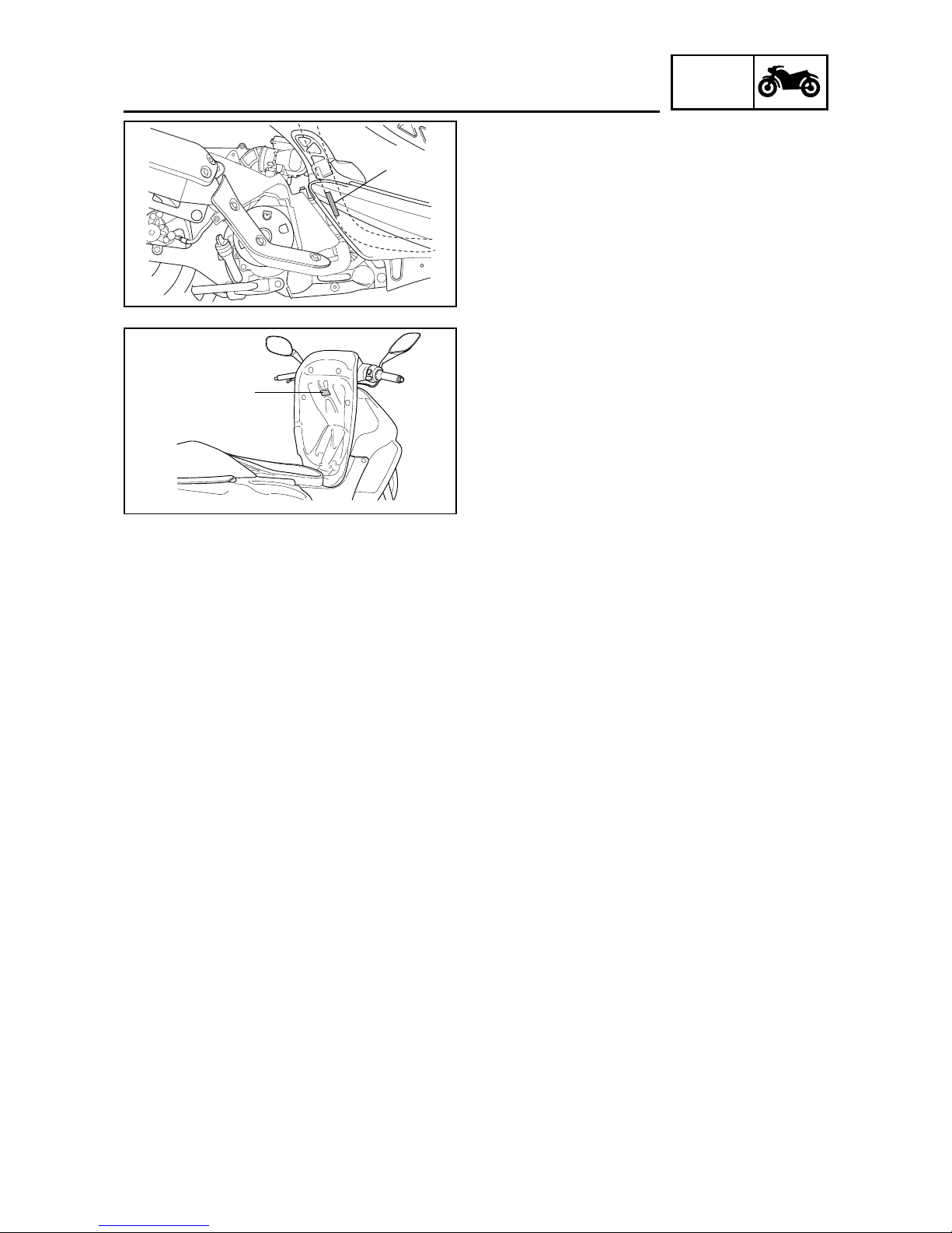
VEHICLE IDENTIFICATION NUMBER
The vehicle identification number 햲 is stamped
into the frame.
EASM0003
MODEL LABEL
The model label 햲 is affixed under the seat.
This information will be needed to order spare
parts.
ZAUM0113
햲
ZAUM0114
햲
1-1

GEN
INFO
1-2
FEATURES
EASM0004
FEATURES
OIL INDICATOR LIGHT
• FUNCTION
Pulses (travel distance signals) from the speedometer are counted and cause the oil indicator light
to come on at 500 km for the first time and thereafter every 3,000 km. In this way, the light indicates
the time for oil change.
• RESETTING PROCEDURE
To reset the oil change indicator light
1) Press the “TRIP” button while turning the key to “ON”.
2) Release the button and the oil change indicator light will go off.
NOTE:
To reset the oil change indicator light before the periodic oil change interval has been reached, follow
the above procedure.
ODOMETER/TRIPMETER READING MODE
The odometer and tripmeter can be set to count in either miles or kilometers according to the following
procedure.
1) Turn the key to “ON”.
2) Press the “TRIP” button until the current mode appears in the dispaly:
“CONT” (continental) for kilometer mode and “EnGL” (English) for the mile mode.
3) Press the “TRIP” button to switch mode.
4) Press the “TRIP” button for two seconds to confirm the setting.
NOTE:
• The odometer/tripmeter reading mode can be changed any number of times while the odometer
reading is below 10, but it cannot changed anymore after the reading has reached 10.
• Switching between the mile and the kilometer mode does not change or convert the current odometer/
tripmeter reading.
BATTERY VOLTAGE/FUEL GAUGE
When the key is turned to “OFF”, the voltage/fuel gauge indicates the battery voltage.
NOTE:
If the battery voltage drops to 10V, refer to “CHECKING THE BATTERY” section in chapter 3.
When the key is turned to “ON”, the voltage/fuel gauge indicates the amount of fuel in the fuel tank
after indicating the battery voltage for two seconds.

GEN
INFO
THE CLOCK
• Setting the clock
To set the clock:
1) Make sure that the key is turned to “OFF”.
2) Press the “TRIP” button for two seconds and the hour display will flash.
3) Press the “TRIP” button to set the hours.
4) Press the “TRIP” button for two seconds, and the first minute digit will flash.
5) Press the “TRIP” button to set the first minute digit.
6) Press the “TRIP” button for two more seconds, and the second minute digit will flash.
7) Press the “TRIP” button to set the second minute digit.
8) Press the “TRIP” button for two seconds to set the clock.
AUTO-CHOKE SYSTEM
This system is the parallel connection of the ignitor unit circuit and the thermo switch as shown,
detecting the engine temperature, and facilitates the restarting with the warm engine.
• Circuit diagram
• Auto-choke operation
FEATURES
Main switch
Fuse
Battery
Thermo
switch
Auto-choke
Ignitor unit
C.P.U
Ignition
Engine condition
Start with the Crank with the Crank with the Restart with the
cold engine cold engine warm engine warm engine
Thermo switch OFF OFF ON ON
Ignitor unit circuit OFF ON ON OFF
Auto-choke Activates Activates Not activate Not activate
1-3

GEN
INFO
EAS00020
IMPORTANT INFORMATION
PREPARATION FOR REMOVAL AND
DISASSEMBLY
1.Before removal and disassembly, remove all
dirt, mud, dust and foreign material.
2.Use only the proper tools and cleaning equipment.
Refer to the “SPECIAL TOOLS”.
3. When disassembling, always keep mated parts
together. This includes gears, cylinders, pistons and other parts that have been “mated”
through normal wear. Mated parts must always be reused or replaced as an assembly.
4.During disassembly, clean all of the parts and
place them in trays in the order of disassembly. This will speed up assembly and allow for
the correct installation of all parts.
5.Keep all parts away from any source of fire.
EAS00021
REPLACEMENT PARTS
1.Use only genuine Yamaha and MBK parts for
all replacements. Use oil and grease recommended by Yamaha or MBK for all lubrication
jobs. Other brands may be similar in function
and appearance, but inferior in quality.
EAS00022
GASKETS, OIL SEALS AND O-RINGS
1.When overhauling the engine, replace all gaskets, seals and O-rings. All gasket surfaces,
oil seal lips and O-rings must be cleaned.
2.During reassembly, properly oil all mating
parts and bearings and lubricate the oil seal
lips with grease.
IMPORTANT INFORMATION
1-4
 Loading...