

Yamaha XP530E-A, XP530D-A, XP530-A Owner's Manual

OWNER’S MANUAL
Read this manual carefully before oper-
ating this vehicle.
TMAX ABS
MOTORCYCLE
XP530E-A
XP530-A
XP530D-A
BV1-28199-E0
Read this manual carefully before operating this vehicle. This manual
should stay with this vehicle if it is sold.
EAU77940
For XP530-A and XP530D-A
EAU79571


Introduction
WARNING
EAU10114
Welcome to the Yamaha world of motorcycling!
As the owner of the XP530E-A/XP530-A/XP530D-A, you are benefiting from
Yamaha’s vast experience and newest technology regarding the design and manufacture of high-quality products, which have earned Yamaha a reputation for dependability.
Please take the time to read this manual thoroughly, so as to enjoy all advantages
of your XP530E-A/XP530-A/XP530D-A. The Owner’s Manual does not only instruct you in how to operate, inspect and maintain your scooter, but also in how to
safeguard yourself and others from trouble and injury.
In addition, the many tips given in this manual will help keep your scooter in the
best possible condition. If you have any further questions, do not hesitate to contact your Yamaha dealer.
The Yamaha team wishes you many safe and pleasant rides. So, remember to put
safety first!
Yamaha continually seeks advancements in product design and quality. Therefore, while this manual contains the most current product information available at
the time of printing, there may be minor discrepancies between your scooter and
this manual. If there is any question concerning this manual, please consult a
Yamaha dealer.
EWA12412
Please read this manual carefully and completely before operating this
scooter.
Important manual information
WARNING
NOTICE
TIP
EAU63350
Particularly important information is distinguished in this manual by the following
notations:
This is the safety alert symbol. It is used to
alert you to potential personal injury hazards.
Obey all safety messages that follow this
symbol to avoid possible injury or death.
A WARNING indicates a hazardous situation
which, if not avoided, could result in death or
serious injury.
A NOTICE indicates special precautions that
must be taken to avoid damage to the vehicle
or other property.
A TIP provides key information to make procedures easier or clearer.
*Product and specifications are subject to change without notice.
EAU10201
XP530E-A/XP530-A/XP530D-A
OWNER’S MANUAL
©2016 by Yamaha Motor Co., Ltd.
1st edition, October 2016
All rights reserved.
Any reprinting or unauthorized use
without the written permission of
Yamaha Motor Co., Ltd.
is expressly prohibited.
Printed in Japan.

Table of contents
Safety information ............................1-1
Further safe-riding points ................ 1-5
Description ........................................2-1
Left view .......................................... 2-1
Right view........................................2-2
Controls and instruments ................2-3
Smart key system ............................3-1
Smart key system............................3-1
Operating range of the smart key
system..........................................3-2
Handling of the smart key and
mechanical key ............................ 3-3
Smart key ........................................3-5
Replacing the smart key battery...... 3-6
Powering on the vehicle ..................3-7
Powering off the vehicle ..................3-8
How to lock the steering ..................3-9
How to lock the centerstand .......... 3-10
Storage compartment and fuel
tank access................................3-10
Parking mode ................................3-12
Special features ................................4-1
Cruise control system
(XP530D-A)..................................4-1
D-mode (drive mode)
(XP530-A, XP530D-A) .................4-3
Traction control system ...................4-4
Instrument and control functions ...5-1
Handlebar switches.........................5-1
Indicator lights and warning lights ...5-2
Speedometer...................................5-4
Tachometer ..................................... 5-4
Multi-function display....................... 5-5
Front brake lever ........................... 5-17
Rear brake lever............................5-18
Rear brake lock lever ....................5-18
ABS ...............................................5-19
Fuel tank cap.................................5-20
Fuel ...............................................5-21
Fuel tank overflow hose ................ 5-22
Catalytic converter.........................5-23
Storage compartments..................5-23
Windshield
(XP530E-A, XP530-A) ............... 5-25
Rear view mirrors.......................... 5-26
Shock absorber assembly............. 5-27
Auxiliary DC jack........................... 5-28
Sidestand ...................................... 5-29
Ignition circuit cut-off system......... 5-30
For your safety – pre-operation
checks ............................................... 6-1
Operation and important riding
points................................................. 7-1
Starting the engine.......................... 7-2
Starting off....................................... 7-3
Acceleration and deceleration......... 7-3
Braking............................................ 7-4
Tips for reducing fuel
consumption ................................ 7-5
Engine break-in............................... 7-5
Parking............................................ 7-6
Periodic maintenance and
adjustment ........................................ 8-1
Owner’s tool kit ............................... 8-2
Periodic maintenance chart for the
emission control system .............. 8-3
General maintenance and
lubrication chart ........................... 8-4
Removing and installing panels ...... 8-7
Checking the spark plugs................ 8-9
Canister......................................... 8-10
Engine oil and oil filter cartridge.... 8-10
Coolant.......................................... 8-14
Replacing the air filter element ..... 8-15
Checking the engine idling
speed......................................... 8-16
Checking the throttle grip free
play ............................................ 8-17
Valve clearance ............................ 8-17
Tires .............................................. 8-18
Cast wheels .................................. 8-20
Checking the front and rear
brake lever free play .................. 8-20
Adjusting the rear brake lock
cable .......................................... 8-21

Table of contents
Checking the rear brake lock.........8-22
Checking the front and rear brake
pads ...........................................8-22
Checking the brake fluid level........8-23
Changing the brake fluid................8-24
Drive belt slack ..............................8-24
Checking and lubricating the
cables.........................................8-25
Checking and lubricating the
throttle grip and cable.................8-25
Lubricating the front and rear
brake levers................................8-26
Checking and lubricating the
centerstand and sidestand .........8-26
Checking the front fork ..................8-27
Checking the steering....................8-27
Checking the wheel bearings ........8-28
Battery ...........................................8-28
Replacing the fuses .......................8-30
Vehicle lights .................................8-32
Replacing a front turn signal light
bulb ............................................8-33
Replacing the license plate light
bulb ............................................8-33
Troubleshooting.............................8-34
Troubleshooting charts ..................8-35
Emergency mode ..........................8-37
Scooter care and storage.................9-1
Matte color caution ..........................9-1
Care.................................................9-1
Storage ............................................9-4
Specifications..................................10-1
Consumer information ...................11-1
Identification numbers ...................11-1
Diagnostic connector .....................11-2
Vehicle data recording...................11-2
Index.................................................12-1

Safety information
EAU1026B
Be a Responsible Owner
As the vehicle’s owner, you are responsible for the safe and proper operation
of your scooter.
Scooters are single-track vehicles.
Their safe use and operation are dependent upon the use of proper riding
techniques as well as the expertise of
the operator. Every operator should
know the following requirements before
riding this scooter.
He or she should:
Obtain thorough instructions from
a competent source on all aspects
of scooter operation.
Observe the warnings and mainte-
nance requirements in this Owner’s Manual.
Obtain qualified training in safe
and proper riding techniques.
Obtain professional technical ser-
vice as indicated in this Owner’s
Manual and/or when made necessary by mechanical conditions.
Never operate a scooter without
proper training or instruction. Take
a training course. Beginners
should receive training from a certified instructor. Contact an authorized scooter dealer to find out
about the training courses nearest
you.
Safe Riding
Perform the pre-operation checks each
time you use the vehicle to make sure it
is in safe operating condition. Failure to
inspect or maintain the vehicle properly
increases the possibility of an accident
or equipment damage. See page 6-1
for a list of pre-operation checks.
This scooter is designed to carry
the operator and a passenger.
The failure of motorists to detect
and recognize scooters in traffic is
the predominating cause of automobile/scooter accidents. Many
accidents have been caused by an
automobile driver who did not see
the scooter. Making yourself conspicuous appears to be very effective in reducing the chance of this
type of accident.
Therefore:
• Wear a brightly colored jacket.
• Use extra caution when you are
approaching and passing
through intersections, since intersections are the most likely
places for scooter accidents to
occur.
• Ride where other motorists can
see you. Avoid riding in another
motorist’s blind spot.
• Never maintain a scooter without proper knowledge. Contact
an authorized scooter dealer to
inform you on basic scooter
maintenance. Certain maintenance can only be carried out by
certified staff.
Many accidents involve inexperi-
enced operators. In fact, many operators who have been involved in
accidents do not even have a current driver’s license.
• Make sure that you are qualified
and that you only lend your
scooter to other qualified operators.
• Know your skills and limits.
Staying within your limits may
1
2
3
4
5
6
7
8
9
10
11
12
13
14
1-1

Safety information
10
11
12
13
14
help you to avoid an accident.
• We recommend that you practice riding your scooter where
1
there is no traffic until you have
become thoroughly familiar with
the scooter and all of its con-
2
trols.
Many accidents have been caused
by error of the scooter operator. A
3
typical error made by the operator
is veering wide on a turn due to excessive speed or undercornering
4
(insufficient lean angle for the
speed).
• Always obey the speed limit and
5
never travel faster than warranted by road and traffic conditions.
• Always signal before turning or
6
changing lanes. Make sure that
other motorists can see you.
The posture of the operator and
7
passenger is important for proper
control.
8
• The operator should keep both
hands on the handlebar and
both feet on the operator foot-
9
rests during operation to maintain control of the scooter.
• The passenger should always
hold onto the operator, the seat
strap or grab bar, if equipped,
with both hands and keep both
feet on the passenger footrests.
Never carry a passenger unless
he or she can firmly place both
feet on the passenger footrests.
Never ride under the influence of
alcohol or other drugs.
This scooter is designed for on-
road use only. It is not suitable for
off-road use.
Protective Apparel
The majority of fatalities from scooter
accidents are the result of head injuries. The use of a safety helmet is the
single most critical factor in the prevention or reduction of head injuries.
Always wear an approved helmet.
Wear a face shield or goggles.
Wind in your unprotected eyes
could contribute to an impairment
of vision that could delay seeing a
hazard.
The use of a jacket, substantial
shoes, trousers, gloves, etc., is effective in preventing or reducing
abrasions or lacerations.
Never wear loose-fitting clothes,
otherwise they could catch on the
control levers or wheels and cause
injury or an accident.
Always wear protective clothing
that covers your legs, ankles, and
feet. The engine or exhaust system become very hot during or after operation and can cause burns.
A passenger should also observe
the above precautions.
Avoid Carbon Monoxide Poisoning
All engine exhaust contains carbon
monoxide, a deadly gas. Breathing carbon monoxide can cause headaches,
dizziness, drowsiness, nausea, confusion, and eventually death.
Carbon Monoxide is a colorless, odorless, tasteless gas which may be present even if you do not see or smell any
engine exhaust. Deadly levels of carbon monoxide can collect rapidly and
you can quickly be overcome and unable to save yourself. Also, deadly levels of carbon monoxide can linger for
1-2

Safety information
hours or days in enclosed or poorly
ventilated areas. If you experience any
symptoms of carbon monoxide poisoning, leave the area immediately, get
fresh air, and SEEK MEDICAL TREATMENT.
Do not run engine indoors. Even if
you try to ventilate engine exhaust
with fans or open windows and
doors, carbon monoxide can rapidly reach dangerous levels.
Do not run engine in poorly venti-
lated or partially enclosed areas
such as barns, garages, or carports.
Do not run engine outdoors where
engine exhaust can be drawn into
a building through openings such
as windows and doors.
Loading
Adding accessories or cargo to your
scooter can adversely affect stability
and handling if the weight distribution of
the scooter is changed. To avoid the
possibility of an accident, use extreme
caution when adding cargo or accessories to your scooter. Use extra care
when riding a scooter that has added
cargo or accessories. Here, along with
the information about accessories below, are some general guidelines to follow if loading cargo to your scooter:
The total weight of the operator, passenger, accessories and cargo must
not exceed the maximum load limit.
Operation of an overloaded vehicle
could cause an accident.
Maximum load:
199 kg (439 lb) (XP530D-A)
202 kg (445 lb) (XP530-A, XP530EA)
When loading within this weight limit,
keep the following in mind:
Cargo and accessory weight
should be kept as low and close to
the scooter as possible. Securely
pack your heaviest items as close
to the center of the vehicle as possible and make sure to distribute
the weight as evenly as possible
on both sides of the scooter to minimize imbalance or instability.
Shifting weights can create a sud-
den imbalance. Make sure that accessories and cargo are securely
attached to the scooter before riding. Check accessory mounts and
cargo restraints frequently.
• Properly adjust the suspension
for your load (suspension-adjustable models only), and
check the condition and pressure of your tires.
• Never attach any large or heavy
items to the handlebar, front
fork, or front fender. Such items
can create unstable handling or
a slow steering response.
This vehicle is not designed to
pull a trailer or to be attached to
a sidecar.
Genuine Yamaha Accessories
Choosing accessories for your vehicle
is an important decision. Genuine
Yamaha accessories, which are available only from a Yamaha dealer, have
been designed, tested, and approved
by Yamaha for use on your vehicle.
Many companies with no connection to
Yamaha manufacture parts and accessories or offer other modifications for
Yamaha vehicles. Yamaha is not in a
1
2
3
4
5
6
7
8
9
10
11
12
13
14
1-3

Safety information
position to test the products that these
aftermarket companies produce.
Therefore, Yamaha can neither endorse nor recommend the use of ac-
1
cessories not sold by Yamaha or
modifications not specifically recommended by Yamaha, even if sold and
2
installed by a Yamaha dealer.
Aftermarket Parts, Accessories,
3
and Modifications
While you may find aftermarket products similar in design and quality to
4
genuine Yamaha accessories, recognize that some aftermarket accessories
5
or modifications are not suitable because of potential safety hazards to you
or others. Installing aftermarket prod-
6
ucts or having other modifications performed to your vehicle that change any
of the vehicle’s design or operation
7
characteristics can put you and others
at greater risk of serious injury or death.
You are responsible for injuries related
8
to changes in the vehicle.
Keep the following guidelines in mind,
as well as those provided under “Load-
9
ing” when mounting accessories.
Never install accessories or carry
10
11
12
13
14
cargo that would impair the performance of your scooter. Carefully
inspect the accessory before using
it to make sure that it does not in
any way reduce ground clearance
or cornering clearance, limit suspension travel, steering travel or
control operation, or obscure lights
or reflectors.
• Accessories fitted to the handlebar or the front fork area can create instability due to improper
weight distribution or aerody-
namic changes. If accessories
are added to the handlebar or
front fork area, they must be as
lightweight as possible and
should be kept to a minimum.
• Bulky or large accessories may
seriously affect the stability of
the scooter due to aerodynamic
effects. Wind may attempt to lift
the scooter, or the scooter may
become unstable in cross
winds. These accessories may
also cause instability when
passing or being passed by
large vehicles.
• Certain accessories can displace the operator from his or
her normal riding position. This
improper position limits the freedom of movement of the operator and may limit control ability,
therefore, such accessories are
not recommended.
Use caution when adding electrical
accessories. If electrical accessories exceed the capacity of the
scooter’s electrical system, an
electric failure could result, which
could cause a dangerous loss of
lights or engine power.
Aftermarket Tires and Rims
The tires and rims that came with your
scooter were designed to match the
performance capabilities and to provide
the best combination of handling, braking, and comfort. Other tires, rims, sizes, and combinations may not be
appropriate. Refer to page 8-18 for tire
specifications and more information on
replacing your tires.
1-4

Safety information
Transporting the Scooter
Be sure to observe following instructions before transporting the scooter in
another vehicle.
Remove all loose items from the
scooter.
Point the front wheel straight
ahead on the trailer or in the truck
bed, and choke it in a rail to prevent movement.
Secure the scooter with tie-downs
or suitable straps that are attached
to solid parts of the scooter, such
as the frame or upper front fork triple clamp (and not, for example, to
rubber-mounted handlebars or
turn signals, or parts that could
break). Choose the location for the
straps carefully so the straps will
not rub against painted surfaces
during transport.
The suspension should be com-
pressed somewhat by the tiedowns, if possible, so that the
scooter will not bounce excessively during transport.
EAU57600
Further safe-riding points
Be sure to signal clearly when
making turns.
Braking can be extremely difficult
on a wet road. Avoid hard braking,
because the scooter could slide.
Apply the brakes slowly when
stopping on a wet surface.
Slow down as you approach a cor-
ner or turn. Once you have completed a turn, accelerate slowly.
Be careful when passing parked
cars. A driver might not see you
and open a door in your path.
Railroad crossings, streetcar rails,
iron plates on road construction
sites, and manhole covers become extremely slippery when
wet. Slow down and cross them
with caution. Keep the scooter upright, otherwise it could slide out
from under you.
The brake pads or linings could get
wet when you wash the scooter.
After washing the scooter, check
the brakes before riding.
Always wear a helmet, gloves,
trousers (tapered around the cuff
and ankle so they do not flap), and
a brightly colored jacket.
Do not carry too much luggage on
the scooter. An overloaded scooter is unstable. Use a strong cord to
secure any luggage to the carrier
(if equipped). A loose load will affect the stability of the scooter and
could divert your attention from the
road. (See page 1-3.)
1
2
3
4
5
6
7
8
9
10
11
12
13
1-5
14
Description
1
2
34 5
976810
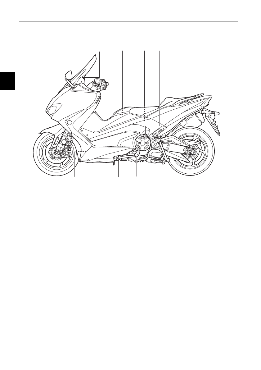
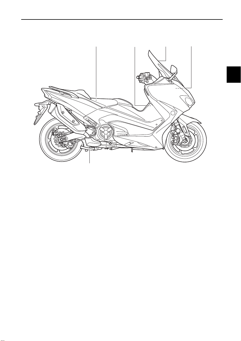
Left view
1
2
3
4
5
6
7
1. Battery (page 8-28)
2. Fuel tank cap (page 5-20)
3. Rear storage compartment (page 5-23)
8
4. Engine oil filler cap (page 8-10)
5. Grab bar (page 7-3)
6. Sidestand (page 5-29)
9
7. Engine oil drain bolt (page 8-10)
8. Engine oil level check window (page 8-10)
9. Oil filter cartridge (page 8-10)
10
10.Coolant level check window (page 8-14)
EAU63371
11
12
13
14
2-1
Right view
1
2
34
5
Description
EAU63391
1
2
3
4
5
6
1. Owner’s tool kit (page 8-2)
2. Air filter element (page 8-15)
3. Windshield (page 5-25/5-7)
4. Fuses (page 8-30)
5. Centerstand (page 8-26)
7
8
9
10
11
12
13
14
2-2
Description
1 23456 7 8
10, 11
1212
9
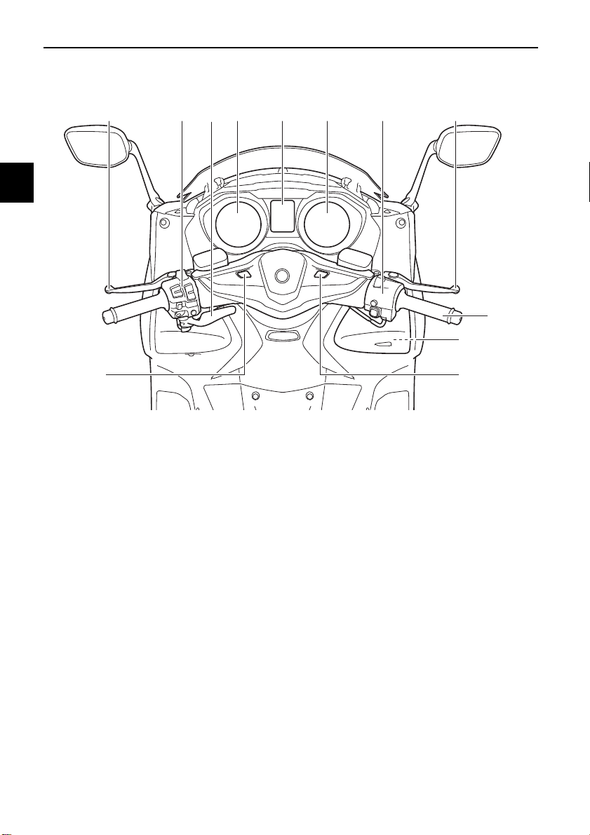
Controls and instruments
1
2
3
4
5
6
7
1. Rear brake lever (page 5-18)
2. Left handlebar switches (page 5-1)
3. Rear brake lock lever (page 5-18)
8
4. Speedometer (page 5-4)
5. Multi-function display (page 5-5)
6. Tachometer (page 5-4)
9
7. Right handlebar switches (page 5-1)
8. Front brake lever (page 5-17)
9. Throttle grip (page 8-17)
10.Front storage compartment (page 5-23)
10
11.Auxiliary DC jack (page 5-28)
12.Smart key system switches (page 3-1)
11
EAU63401
12
13
14
2-3
EAU77201
WARNING
1
1
1
1
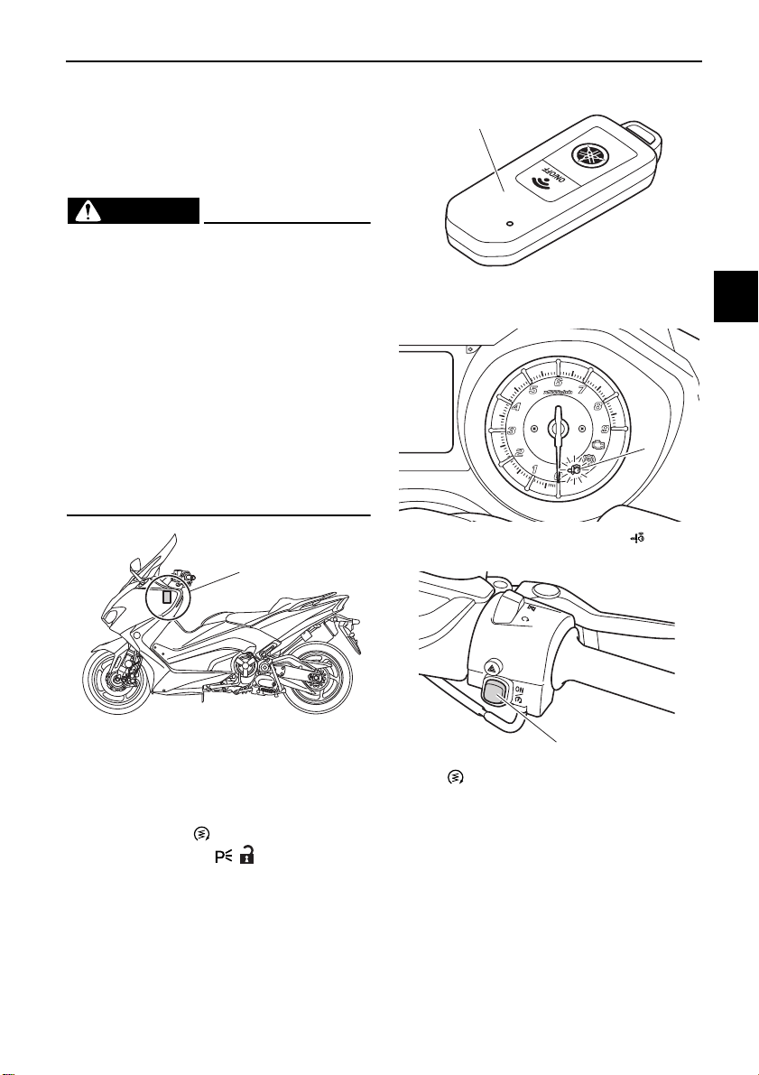
Smart key system
The smart key system enables the vehicle to be operated without using a
mechanical key.
EWA14704
Smart key system
1
Keep implanted pacemakers or
cardiac defibrillators, as well as
other electric medical devices
away from the vehicle mounted
antenna (see illustration).
Radio waves transmitted by the
antenna may affect the operation of such devices when close
by.
If you have an electric medical
device, consult a doctor or the
device manufacturer before using this vehicle.
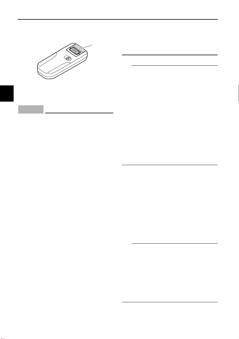
1. Vehicle mounted antenna
1. Smart key
1. Smart key system indicator light “ ”
2
3
4
5
6
7
8
9
10
In addition to the vehicle mounted antenna, the smart key system consists of
the smart key, smart key system indicator light, “ON/ ” switch, and the
“OFF/LOCK” and “ / ” switches.
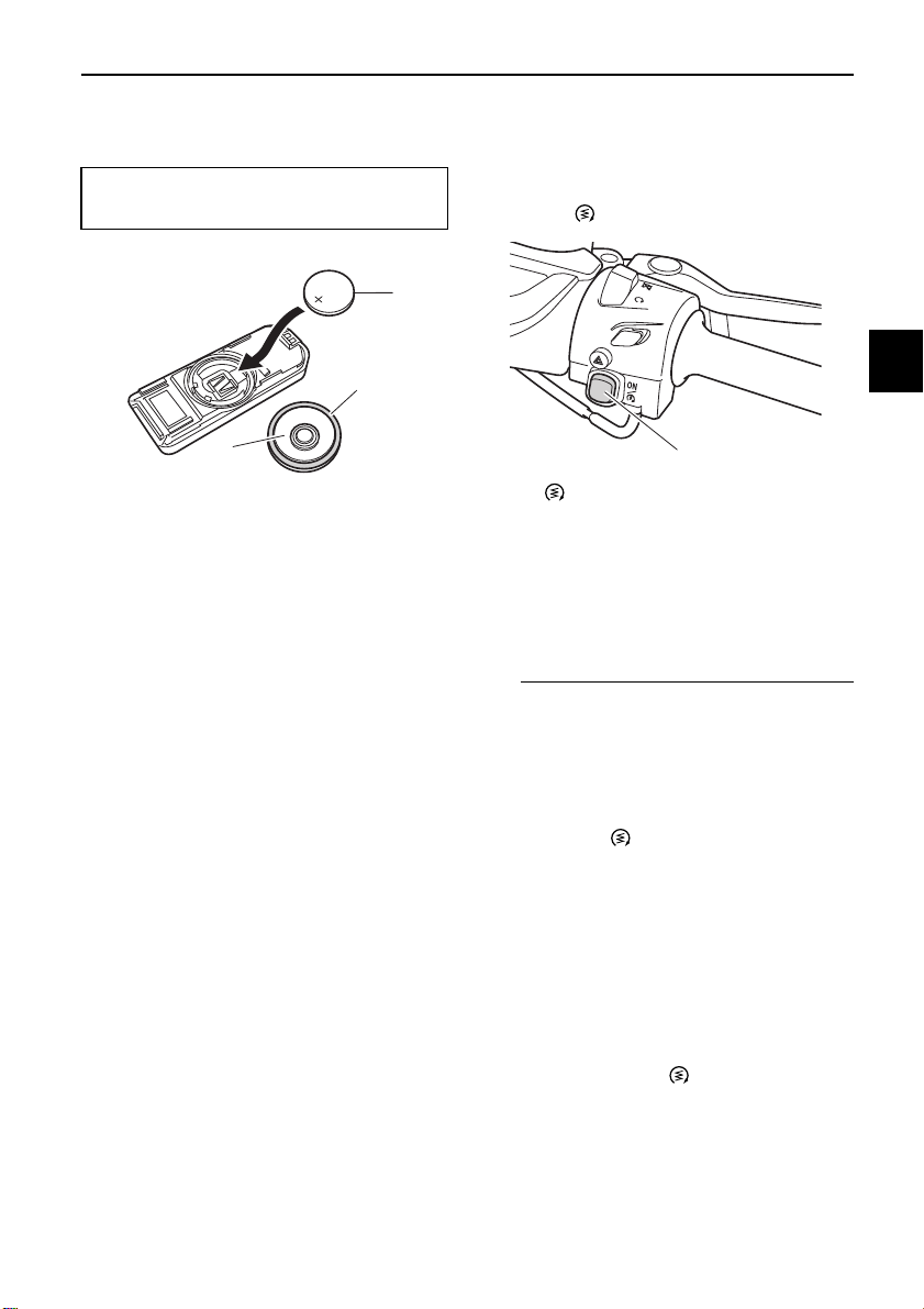
1. “ON/ ” switch
3-1
11
12
13
14
Smart key system
NOTICE
TIP
12
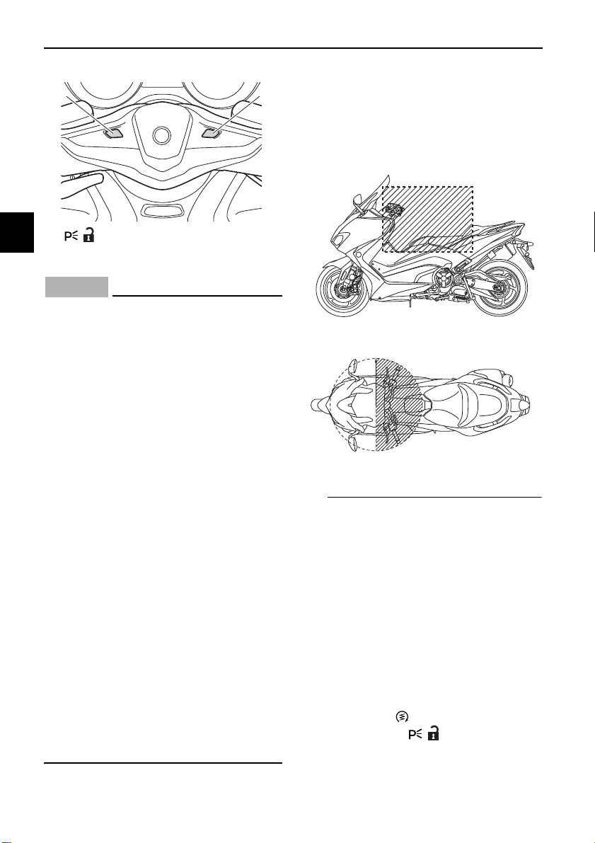
Operating range of the smart key system
1
2
3
1. “ / ” switch
2. “OFF/LOCK” switch
4
ECA15764
The smart key system uses weak radio waves. The smart key system
5
may not work in the following situations.
6
The smart key is placed in a lo-
cation exposed to strong radio
waves or other electromagnetic
7
8
noise
There are facilities nearby that
are emitting strong radio waves
(TV or radio towers, power
plants, broadcasting stations,
9
airports, etc.)
You are carrying or using com-
munication equipment such as
10
radios or mobile phones in
close proximity of the smart key
The smart key is in contact with
11
or covered by a metallic object
Other vehicles equipped with a
smart key system are nearby
12
In such situations, move the smart
key to another location and perform
the operation again. If it still does
13
not work, use the mechanical key to
carry out the operation in emergency mode. (See page 8-37.)
14
The operating range of the smart key
system is about 80 cm (31.5 in) from
the center of the handlebars.
As the smart key system uses
weak radio waves, the operating
range may be affected by the surrounding environment.
When the battery of the smart key
is discharged, the smart key may
not work or its operating range become very small.
If the smart key is turned off, the
vehicle will not recognize the smart
key even if it is within operating
range.
If the “ON/ ” switch, “OFF/LOCK”
switch, or “ / ” switch are repeatedly pressed when the smart
key is out of range or cannot com-
EAU77212
3-2
Smart key system
WARNING
TIP
123456
123
municate with the vehicle, all
switches will be temporarily disabled.
Placing the smart key in the front
or rear storage compartment may
block communication between the
smart key and the vehicle. If the
rear trunk or front storage compartment (XP530D-A) is locked
with the smart key inside, the
smart key system may be disabled. The smart key should always carried on your person.
EWA17952
The smart key should be carried
with you. Do not store it on the
vehicle.
When the smart key is within op-
erating range, exercise due care
because other people not carrying the smart key can start the
engine and operate the vehicle.
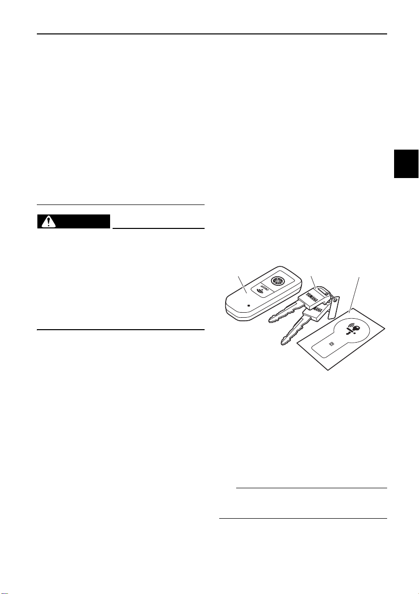
EAU61646
Handling of the smart key and mechanical key
Included with the vehicle is one smart
key (with a built-in mechanical key) and
one spare mechanical key with an identification card. Keep the spare mechanical key and card separate from the
smart key. Should you lose or damage
the smart key, or when its battery is discharged, the mechanical key will serve
as a back up. The seat can be opened,
the smart key system identification
number can be manually input, and
then the vehicle can be operated. (See
page 8-37.) We recommend that you
note down the identification number
in case of emergency.
1
2
3
4
5
6
7
8
1. Smart key
2. Mechanical key
3. Identification number card
If the smart key and identification card
of the mechanical key are both lost or
damaged, and there is no record of the
identification number, the entire smart
key system will need to be replaced.
The identification number can also be
found on the smart key itself.
3-3
9
10
11
12
13
14
Smart key system
NOTICE
TIP
TIP
1
1
chemicals to come in contact
with the smart key. The smart
key body may become discolored or cracked.
2
3
1. Identification number
4
The smart key has precision electronic components. Observe the following precautions to prevent
5
possible malfunction or damage.
Do not place or store the smart
6
key in a storage compartment.
The smart key may be damaged
from road vibrations or exces-
7
8
sive heat.
Do not drop, bend, or subject
the smart key to strong impacts.
Do not submerge the smart key
in water or other liquids.
Do not place heavy items or ex-
9
10
cessive stress on the smart key.
Do not leave the smart key in a
place exposed to direct sunlight, high temperature or high
humidity.
11
Do not grind or attempt to mod-
ify the smart key.
Keep the smart key away from
12
strong magnetic fields and magnetic objects such as key holders, TVs, and computers.
13
14
Keep the smart key away from
electric medical equipment.
Do not allow oils, polishing
agents, fuel, or any strong
ECA21573
The smart key battery life is ap-
proximately two years, but this
may vary according to operating
conditions.
The smart key battery may be-
come discharged even if it is away
from the vehicle and not being
used.
If the smart key continually re-
ceives radio waves, the smart key
battery will discharge quickly. (For
example, when placed in the vicinity of electrical products such as
televisions, radios, or computers.)
Replace the smart key battery when
the smart key system indicator light
flashes for about 20 seconds when the
vehicle is first power on, or when the
smart key indicator light does not come
on when the “ON/OFF” switch is
pushed. (See page 3-6.) After changing
the smart key battery, if the smart key
system still does not operate, have a
Yamaha dealer check the vehicle.
You can register up to six smart
keys for the same vehicle. See a
Yamaha dealer regarding spare
smart keys.
If a smart key is lost, contact a
Yamaha dealer immediately to
prevent the vehicle from being stolen.
3-4
Smart key system
TIP
1
2
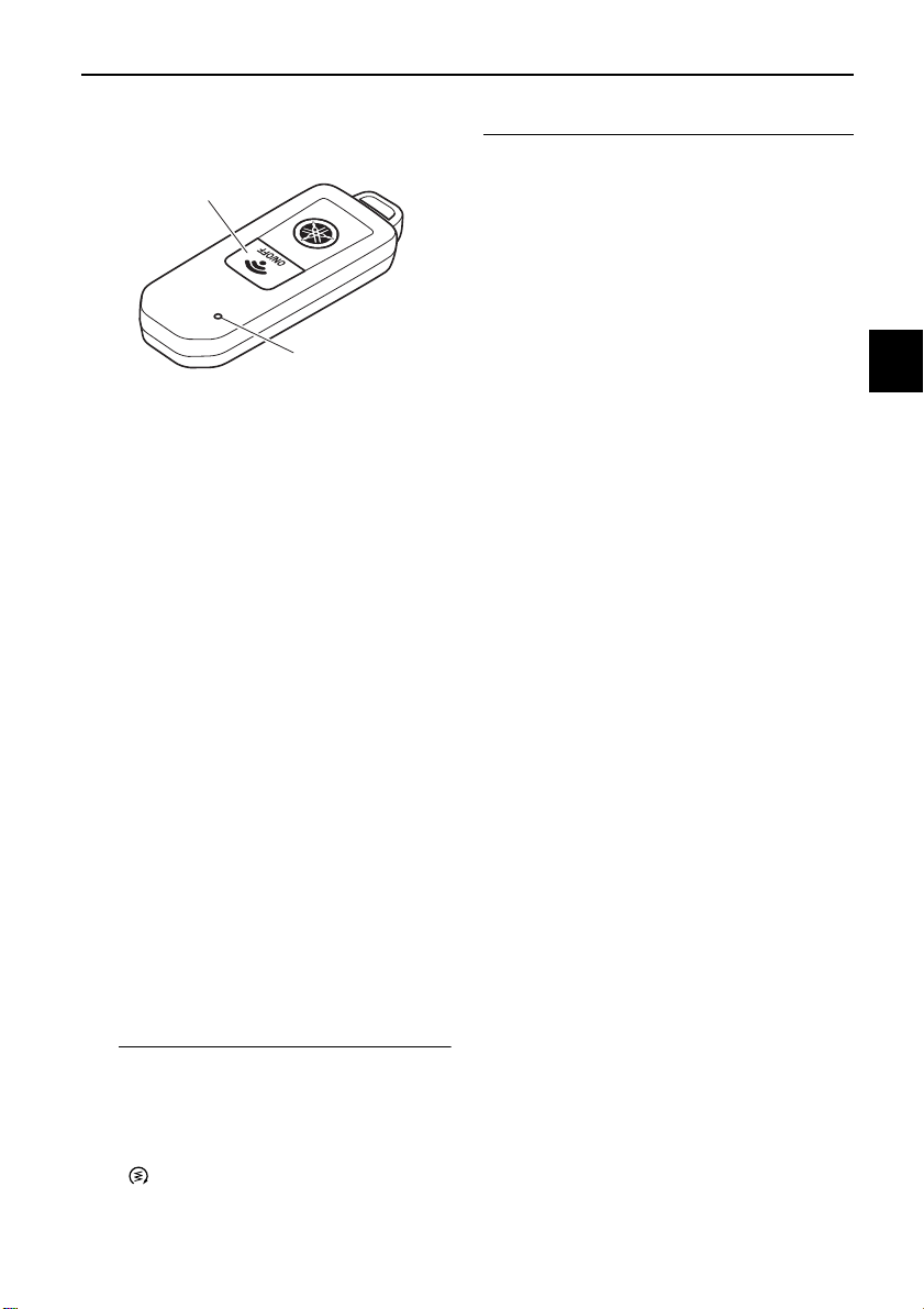
EAU77223
Smart key
1. “ON/OFF” switch
2. Smart key indicator light
When the smart key is turned on and
brought within range, the smart key
system allows you to operate the vehicle without inserting a mechanical key.
If the smart key is turned off, the vehicle
cannot be operated even if the smart
key is within operating range of the vehicle.
The current status of the key can be
checked by briefly pressing the
“ON/OFF” switch.
Short flash: the key is on
Long flash: the key is off
To turn the smart key on or off
To turn the smart key on or off, press
the “ON/OFF” switch for one second.
The smart key indicator light will flash. If
the key does a short flash, the key is on.
If the key does a long flash, the key is
off.
To preserve the vehicle battery power,
the smart key system will turn off automatically about a week after the vehicle
is last used. In this case, press the
“ON/ ” switch once to turn on the
smart key system, and then once more
to turn on the vehicle power.
To use the mechanical key
Pull out the mechanical key from the
smart key body. After using the mechanical key, insert it back into the
smart key.
1
2
3
4
5
6
7
8
9
10
11
12
13
14
3-5
Smart key system
WARNING
NOTICE
TIP
1
Replacing the smart key battery
Replace the battery in the following sit-
1
uations.
The smart key system indicator
2
3
4
5
6
7
8
9
10
11
light flashes for about 20 seconds
when the power of the vehicle is
turned on.
When the smart key indicator light
does not come on when the
“ON/OFF” switch is pushed.
1. Smart key system indicator light “ ”
The battery and other remov-
able parts may cause injury if
swallowed. Keep the battery
and other removable parts away
from children.
Do not expose the battery to di-
rect sunlight or other heat
sources.
EAU79070
EWA14724
ECA24010
waterproof seal from being
damaged or contaminated by
dirt.
Do not touch the internal cir-
cuits and terminals. This may
cause malfunctions.
Make sure the battery is in-
stalled correctly. Confirm the direction of the positive/“+” side
of the battery.
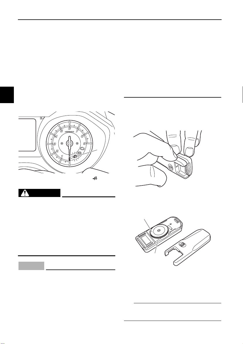
To replace the smart key battery
1. Gently pry open the smart key
case.
2. Remove the battery cover and Oring.
1
2
12
13
14
Do not apply excessive force to
the smart key when replacing
the battery.
Do not use a screwdriver or oth-
er hard object to force open the
key.
Take precautions to prevent the
1. Battery cover
2. O-ring
3. Remove the battery.
Dispose of the removed battery in accordance with local regulations.
3-6
Smart key system
TIP
MODE
1
4. Install a new battery as shown.
Note the polarity of the battery.
Specified battery:
CR2025
1
2
3
1. Battery
2. O-ring
3. Battery cover
5. Install the O-ring and battery cover.
6. Gently snap the smart key case
closed.
EAU77232
Powering on the vehicle
1. With the smart key on and in operating range, briefly press the
“ON/ ” switch.
1. “ON/ ” switch
2. Upon authentication of the smart
key, the beeper will sound twice
and the smart key system indicator
light will come on briefly. All locks
will release automatically.
The smart key system indicator
light will flash if the steering lock
cannot automatically release itself.
Try moving the handlebars gently
to the left or right and then press
the “ON/ ” switch one more time.
If the steering continues to be
locked and will not release, the
smart key system indicator light
will flash 16 times and the steering
lock release operation will stop
midway. Move the handlebar gently to the left and right to help release the steering lock and then
press the “ON/ ” switch again.
The smart key system indicator
light will flash if the centerstand
lock cannot automatically release
itself. Gently rock the vehicle forward or backward and then press
1
2
3
4
5
6
7
8
9
10
11
12
13
14
3-7
Smart key system
NOTICE
TIP
TIP
1
the “ON/ ” switch one more time.
If the centerstand continues to be
locked and will not release, the
1
smart key system indicator light
will flash 16 times and the centerstand lock release operation will
2
stop midway. Rock the vehicle forward and backward to help release
the centerstand lock and then
3
4
press the “ON/ ” switch again.
If the steering lock or centerstand
lock will not release and the smart
key system indicator light is flash-
5
ing, have a Yamaha dealer check the
smart key system.
6
3. The power of the vehicle is turned
on when all locks have been released. The multi-function display
7
will come on.
4. The engine can now be started.
8
(See page 7-2.)
See page 8-37 for information about
9
emergency mode and how to turn the
vehicle power on without the smart key.
10
11
12
13
14
EAU78031
Powering off the vehicle
To turn the vehicle power off and stop
the engine if it is running, press the
“OFF/LOCK” switch.
ECA15826
1. “OFF/LOCK” switch
Upon authentification of the smart key,
the beeper will sound once to confirm
that the vehicle power has been successfully turned off and the storage
compartment and fuel tank cap lid locks
will be released.
The rider must turn off the power of
the vehicle manually.
The power of the vehicle will not
turn off automatically even if the
smart key is moved out of operating range of the smart key system.
The power of the vehicle cannot be
turned off via the “OFF/LOCK”
switch when the vehicle is moving.
If the smart key is not within operating
range or cannot communicate with the
vehicle when you press the
“OFF/LOCK” switch, the vehicle will not
be turned off and the beeper will sound
for three seconds (the smart key system indicator light will also flash) to alert
you that the power was not successfully
turned off. Confirm the location and
condition of the smart key and try pow-
3-8
Smart key system
TIP
TIP
WARNING
ering off the vehicle again.
Without the smart key, the vehicle power can be turned off by pressing the
“OFF/LOCK” switch again while the
smart key system indicator light is
flashing.
Auto lock function
After the engine is stopped via the
“OFF/LOCK” switch, (or whenever the
vehicle power is turned from on to off),
all storage compartment locks (if
equipped) and the fuel tank cap lid lock
are released and these compartments
can be accessed temporarily. When 60
seconds have passed, all compartments will automatically lock.
When the compartment locks are released via the “ / ” switch, the compartments will automatically lock after
10 seconds have passed.
EAU80000
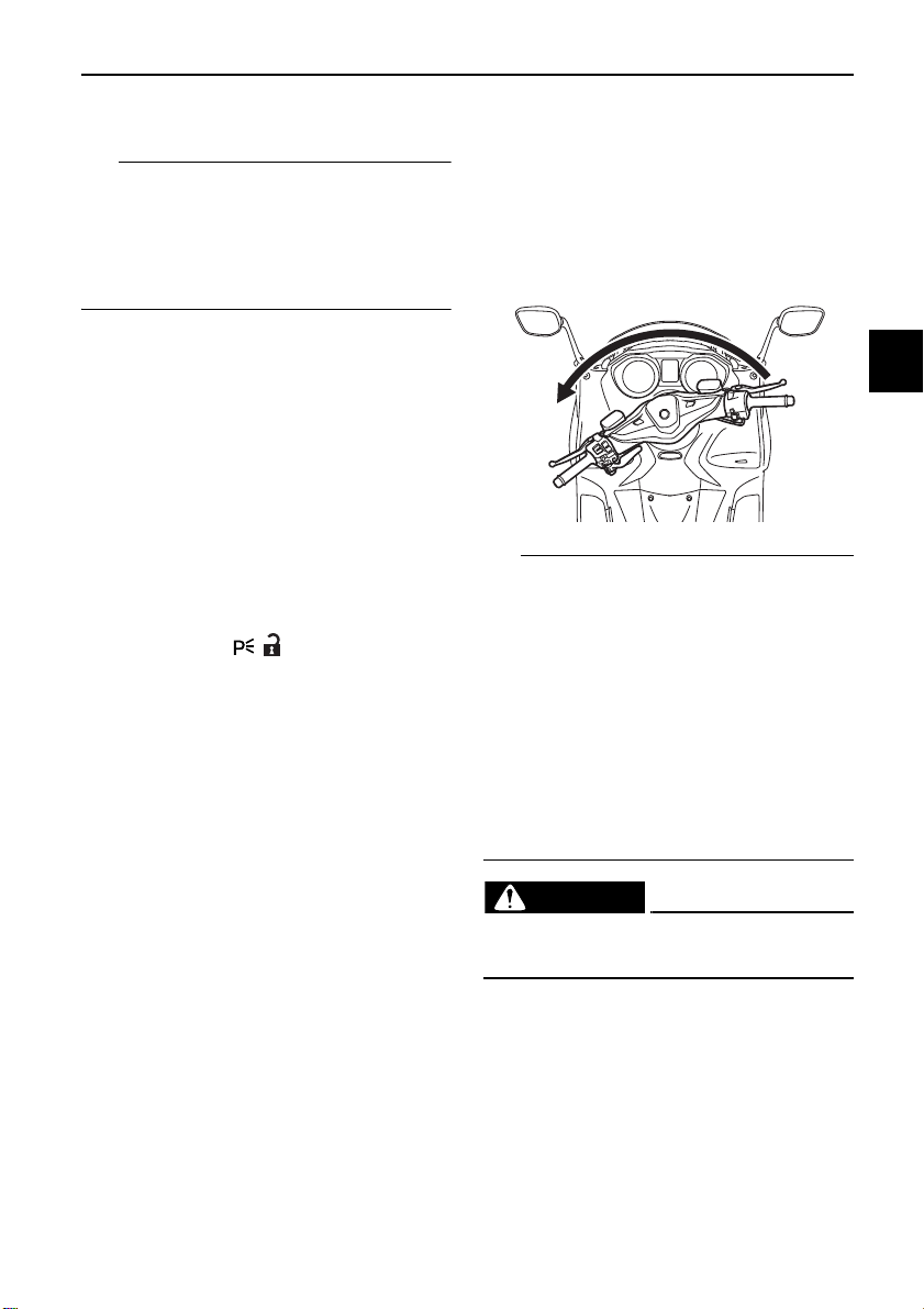
How to lock the steering
After moving the vehicle to a safe parking place, turn off the power of the vehicle. Turn the handlebars fully to the left
and then briefly press the “OFF/LOCK”
switch.
If the steering lock function locks
correctly, the beeper will sound
once.
If the steering lock function does
not lock correctly, the beeper will
sound for three seconds and the
smart key system indicator light
will flash. Turn the handlebar fully
to the left one more time and press
the “OFF/LOCK” switch again for
one second.
EWA14742
1
2
3
4
5
6
7
8
9
10
Do not operate the steering lock
while the vehicle is moving.
3-9
11
12
13
14
Smart key system
TIP
1
1
How to lock the centerstand
Park the vehicle on a firm level surface
and then place it on the centerstand.
1
Press the “OFF/LOCK” switch for one
second.
2
3
4
5
1. “OFF/LOCK” switch
6
If the centerstand lock function
locks correctly, the beeper will
7
8
9
10
sound once.
If the centerstand lock function
does not lock correctly, the beeper
will sound for three seconds and
the smart key system indicator
light will flash. Gently rock the vehicle forward or backward and press
the “OFF/LOCK” switch for one
second.
EAU78052
EAU77243
Storage compartment and fuel tank access
To open the seat
1. Place the vehicle on the centerstand.
2. Briefly press the “ / ” switch.
Upon authentication of the smart
key, the beeper will sound twice.
1
1. “ / ” switch
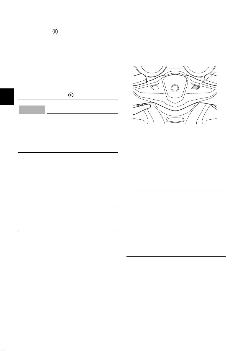
3. Press the “SEAT” button and the
seat lock will release.
11
12
13
14
1. “SEAT” button
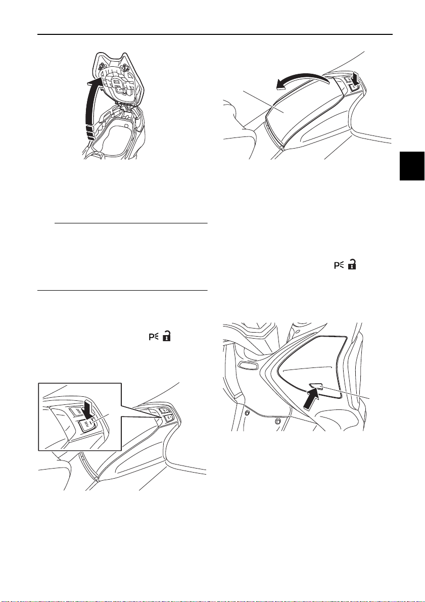
4. Fold the seat up.
3-10
Smart key system
TIP
1
1
1
1
2
To close the seat
Fold the seat down, and then push it to
lock it in place.
Make sure the seat is properly
closed before starting off.
In case of an emergency, the seat
can be opened with a mechanical
key. (See page 8-37.)
To open the fuel tank cap lid
With the smart key on and in operating
range, briefly press the “ / ” switch.
Upon authentication of the smart key,
the beeper will sound twice.
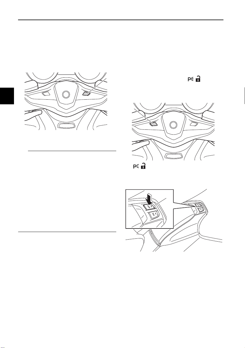
1. Press the “FUEL” button.
1. Fuel tank cap lid
To close the fuel tank cap lid
Push the lid to the original position.
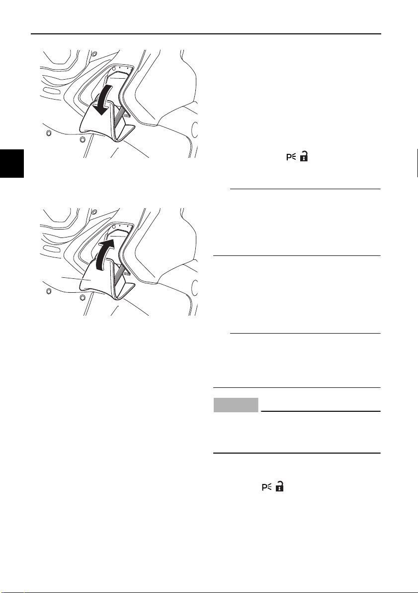
To open the front storage comapartment lid (XP530-A, XP530D-A)
With the smart key on and in operating
range, briefly press the “ / ” switch.
Upon authentication of the smart key,
the beeper will sound twice.
1. Press the button on the center of
the front storage compartment lid.
1. Button
2. Open the front storage compartment as shown.
3
4
5
6
7
8
9
10
11
12
1. “FUEL” button
2. Open the lid as shown.
13
14
3-11
Smart key system
TIP
TIP
NOTICE
1
1
EAU77251
Parking mode
The steering is locked, and the hazard
lights and turn signal lights can be
turned on, but all other electrical systems are off.
2
3
To close the front storage compartment lid
4
Push the lid into the original position.
5
6
7
1. Front storage compartment lid
8
9
10
To enter parking mode
1. Lock the steering. (See page 3-9.)
2. Press the “ / ” switch for one
second.
If the steering lock has not been applied, the beeper will sound for 3 seconds (the smart key system indicator
light will also flash) and the vehicle will
not enter parking mode.
3. Upon authentification of the smart
key, the beeper will sound twice
and the vehicle will enter parking
mode. The smart key system indicator light will come on.
The seat, fuel tank cap lid, and the front
storage compartment (for XP530-A,
XP530D-A) cannot be opened while in
parking mode.
ECA20760
11
12
13
14
Using the hazard or turn signal
lights for an extended length of time
may cause the battery to discharge.
To exit parking mode
Press the “ / ” switch. Upon authentication of the smart key, the beeper will
sound once and the smart key system
indicator light will go off.
3-12
EAU77263
WARNING
TIP
1
2
RES
SET
PASS
1
2
Cruise control system (XP530D-A)
The cruise control system is designed
to maintain a set cruising speed between about 50 km/h (31 mi/h) and 140
km/h (87 mi/h).
EWA16341
Special features
1
2
Improper use of the cruise con-
trol system may result in loss of
control, which could lead to an
accident. Do not activate the
cruise control system in heavy
traffic, poor weather conditions,
or among winding, slippery,
hilly, rough or gravel roads.
When traveling uphill or down-
hill, the cruise control system
may not be able to maintain the
set cruising speed.
To prevent accidentally activat-
ing the cruise control system,
turn it off when not in use. Make
sure that the cruise control system indicator light “ ” is off.
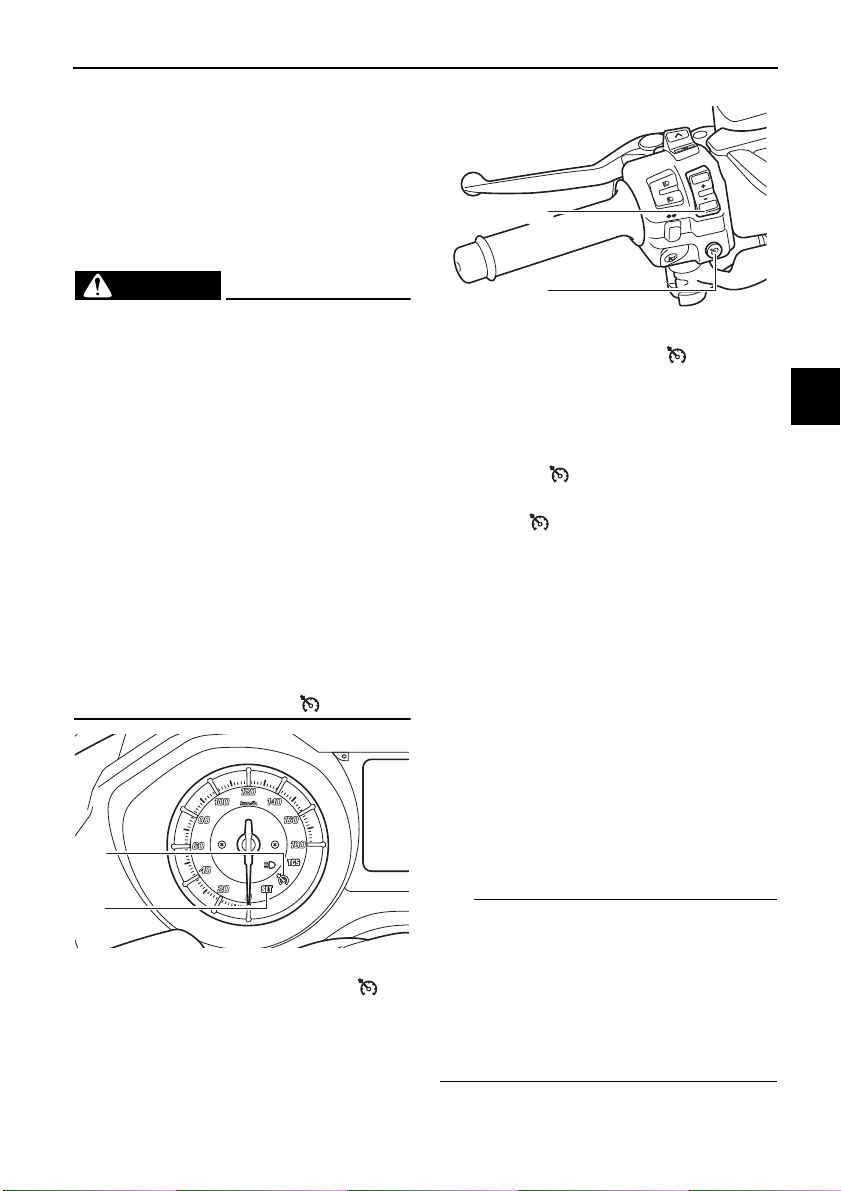
1. Cruise control setting switch “RES+/SET–”
2. Cruise control power switch “ ”
Activating the cruise control system
1. Push the cruise control power
switch “ ” to turn on the system.
The cruise control system indicator
light “ ” will come on.
2. Push the “SET–” side of the cruise
control setting switch to activate
the cruise control system. Your
current traveling speed will become the set cruising speed. The
cruise control setting indicator light
“SET” will come on.
Adjusting the set cruising speed
While the cruise control system is operating, push the “RES+” side of the
cruise control setting switch to increase
the set cruising speed or the “SET–”
side to decrease the set speed.
3
4
5
6
7
8
9
10
11
1. Cruise control setting indicator light “SET”
2. Cruise control system indicator light “ ”
Pushing the setting switch once will
change the speed in increments of approximately 2.0 km/h (1.2 mi/h). Holding down the “RES+” or “SET–” side of
the cruise control setting switch will increase or decrease the speed continuously until the switch is released.
You can also manually increase your
4-1
12
13
14

Special features
TIP
WARNING
TIP
MODE
1
2
traveling speed using the throttle. After
you have accelerated, you can set a
new cruising speed by pushing the
“SET–” side of the setting switch. If you
1
do not set a new cruising speed, when
you return the throttle grip, the vehicle
will decelerate to the previously set
2
cruising speed.
Deactivating the cruise control sys-
3
tem
Perform one of the following operations
to cancel the set cruising speed. The
4
“SET” indicator light will turn off.
Turn the throttle grip past the
5
closed position in the deceleration
direction.
6
7
8
9
1. Closed position
2. Cruise control cancel direction
10
11
Apply the front or rear brake.
Traveling speed decreases as soon as
the cruise control system is deactivated; unless the throttle grip is turned.
12
Using the resume function
Push the “RES+” side of the cruise con-
13
trol setting switch to reactivate the
cruise control system. The traveling
speed will return to the previously set
14
cruising speed. The “SET” indicator
light will come on.
EWA16351
It is dangerous to use the resume
function when the previously set
cruising speed is too high for current conditions.
Turning off the cruise control system
Push the cruise control power switch
“ ” to turn off the cruise control system. The “ ” indicator light and the
“SET” indicator light will turn off.
Whenever the cruise control system or
the vehicle power is turned off, the previously set cruising speed is erased.
You will not be able to use the resume
function until a new cruising speed has
been set.
Automatic deactivation of the cruise
control system
The cruise control system is electronically controlled and linked with other
control systems. The cruise control system will automatically deactivate under
the following conditions:
The cruise control system is not
able to maintain the set cruising
speed (such as when going up a
steep hill).
Wheel slip or wheel spin is detect-
ed. (If the traction control system is
on, traction control will engage.)
Engine trouble, etc.
If the cruise control system is automatically deactivated, the “ ” indicator
light will turn off and the “SET” indicator
light will flash for 4 seconds.
4-2
 Loading...