


SERVICE MANUAL
WaveRunner
VXS
VX1800 (F2W)
VXR
VX1800A (F2W)
F2W-28197-ZU-11

Preface
This manual has been prepared by Yamaha primarily for use by Yamaha dealers and their trained mechanics when performing maintenance procedures and repairs to Yamaha equipment. It has been written to suit the needs of persons who have the Bronze Technical Certificate of the YTA (Yamaha
Technical Academy) marine or the equivalent basic understanding of the mechanical and electrical
concepts and procedures inherent in the work, for without such knowledge attempted repairs or service
to the equipment could render it unsafe or unfit for use.
Because Yamaha has a policy of continuously improving its products, models may differ in detail from
the descriptions and illustrations given in this publication. Use only the latest edition of this manual. Authorized Yamaha dealers are notified periodically of modifications and significant changes in specifications and procedures, and these are incorporated in successive editions of this manual. Also, up-todate parts information is available on YPEC-web. Additional information and up-to-date information on
Yamaha products and services are available on Yamaha Service Portal.
Important information
Particularly important information is distinguished in this manual by the following notations:
The Safety Alert Symbol means ATTENTION! BECOME ALERT! YOUR SAFETY IS INVOLVED!
A WARNING indicates a hazardous situation which, if not avoided, could result in death or serious injury.
A NOTICE indicates special precautions that must be taken to avoid damage to the watercraft
or other property.
TIP:
A TIP provides key information to make procedures easier or clearer.
WaveRunner
VXS, VXR
SERVICE MANUAL
©2015 by Yamaha Motor Co., Ltd.
1st Edition, March 2015
All rights reserved.
Any reprinting or unauthorized use
without the written permission of
Yamaha Motor Co., Ltd.
is expressly prohibited.

Contents
General information
1
Specification
2
Maintenance
3
Fuel system
4
Power unit
5
Jet pump unit
6
Electrical system
7
Hull and hood
8
Troubleshooting
9
Appendix
A

General information
Safety while working.......................................................... 1-1
Rotating parts ............................................................................. 1-1
Hot parts..................................................................................... 1-1
Electric shock ............................................................................. 1-1
Impeller....................................................................................... 1-1
Handling of gasoline................................................................... 1-1
Ventilation................................................................................... 1-1
Self-protection ............................................................................ 1-1
Working with crane..................................................................... 1-2
Handling of heat gun .................................................................. 1-2
Parts, lubricants, and sealants ................................................... 1-2
Handling of sealants................................................................... 1-3
Special service tool .................................................................... 1-3
Tightening torque ....................................................................... 1-3
Non-reusable parts..................................................................... 1-3
Disassembly and assembly........................................................ 1-3
Identification number......................................................... 1-4
Primary I.D. number ................................................................... 1-4
Engine serial number ................................................................. 1-4
Jet pump unit serial number ....................................................... 1-4
Craft identification number (C.I.N.) (Europe).............................. 1-4
Hull identification number (H.I.N.) (Oceania).............................. 1-4
How to use this manual ..................................................... 1-5
Manual format ............................................................................ 1-5
Conditions when testing and adjusting....................................... 1-6
Abbreviation ............................................................................... 1-6
Adhesive, lubricant, sealant,
and thread locking agent................................................... 1-8
Symbols...................................................................................... 1-8
Special service tool............................................................ 1-9
Model feature.................................................................... 1-19
General feature ........................................................................ 1-19
Model equipment comparison table ......................................... 1-20
Technical tips ................................................................... 1-21
Engine control .......................................................................... 1-21

1
General information
RiDE system............................................................................. 1-23
RiDE motor............................................................................... 1-24
ETV system .............................................................................. 1-25
Shift control .............................................................................. 1-26
Engine control system .............................................................. 1-28
Deck and hull............................................................................ 1-31
Lubrication system ................................................................... 1-32
Hose routing ............................................................................. 1-33
Cooling water flow .................................................................... 1-34

Safety while working
1-1
Safety while working
To prevent an accident or injury and to provide
quality service, observe the following safety
procedures.
Rotating parts
Hands, feet, hair, jewelry, clothing, personal
flotation device straps, and so on, can become
entangled with internal rotating parts of the engine or jet pump unit, resulting in serious injury
or death.
• Keep hands, feet, hair, jewelry, clothing, personal flotation device straps, and so on,
away from any exposed moving parts when
operating the engine with the seat removed.
• Keep away from intake grate while engine is
on.
Hot parts
During and after operation, engine parts are
hot enough to cause burns. Do not touch any
parts in the engine compartment until the engine has cooled.
Electric shock
Do not touch any electrical parts while starting
or operating the engine. Otherwise, shock or
electrocution could result.
Impeller
Do not hold the impeller with your hands when
loosening or tightening the impeller.
Handling of gasoline
• Gasoline is highly flammable. Keep gasoline
and all flammable products away from heat,
sparks, and open flames.
• Gasoline is poisonous and can cause injury
or death. Handle gasoline with care. Never
siphon gasoline by mouth. If you swallow
some gasoline, inhale a lot of gasoline vapor,
or get some gasoline in your eyes, see your
doctor immediately. If gasoline spills on your
skin, wash with soap and water. If gasoline
spills on your clothing, change your clothes.
Ventilation
• Gasoline vapor and exhaust gas are heavier
than air and extremely poisonous. If gasoline
vapor or exhaust gas is inhaled in large
quantities, it may cause loss of consciousness and death within a short time.
• When test running an engine indoors (for example, in a water tank) make sure to do so
where adequate ventilation can be maintained.
Self-protection
• Protect your eyes by wearing safety glasses
or safety goggles during all operations involving drilling and grinding, or when using an air
compressor.
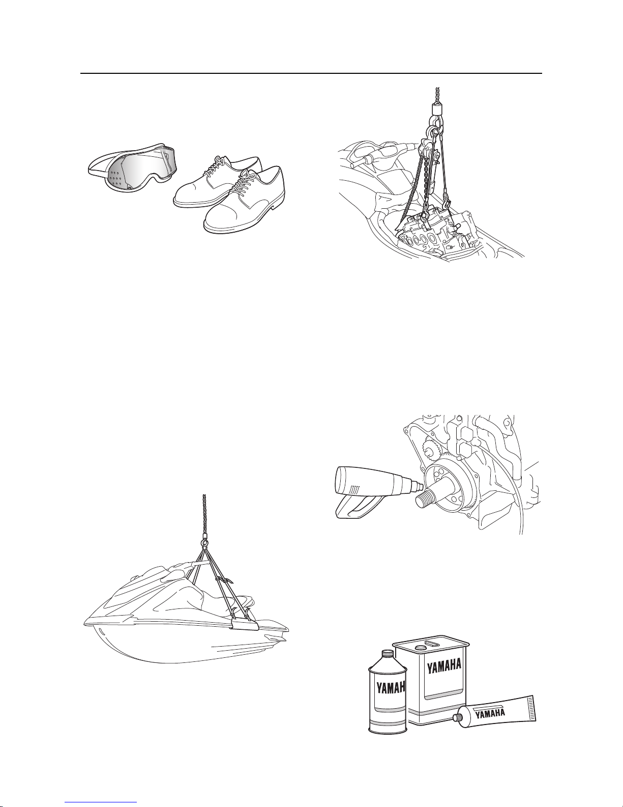
1-2
Safety while working
• Protect your hands and feet by wearing protective gloves and safety shoes when necessary.
Working with crane
• When moving the watercraft, or when lifting
the engine during removal or installation,
make sure to use a crane with a lifting capacity that is equal to or more than the weight of
the watercraft or engine respectively.
• When lifting the watercraft, use the watercraft
lift harness and make sure that the watercraft
is in a stable position when moving it.
• Use the wire ropes of adequate strength, and
lift up the engine unit using the three point
suspension.
• If the engine unit does not have three or more
points to be suspended, support it using additional ropes or the like so that the engine
unit can be lifted and carried in a stable manner.
Handling of heat gun
• Improper handling of a heat gun may result in
burns. For information on the proper handling
of the heat gun, see the operation manual issued by the manufacturer.
• When using a heat gun, keep it away from
the gasoline and oil, to prevent a fire.
• Components become hot enough to cause
burns. Do not touch any hot components directly.
Parts, lubricants, and sealants
Use only genuine Yamaha parts, lubricants,
and sealants, or those recommended by Yamaha, when servicing or repairing the watercraft.

Safety while working
1-3
Handling of sealants
• Wear protective gloves to protect your skin,
when using the sealants.
• See the material safety data sheet issued by
the manufacturer. Some of the sealants may
be harmful to human health.
Special service tool
Use the recommended special service tools to
work safely, and to protect parts from damage.
Tightening torque
Follow the tightening torque specifications provided throughout the manual. When tightening
nuts, bolts, and screws, tighten the large sizes
first, and tighten fasteners starting in the center
and moving outward.
Non-reusable parts
Always use new gaskets, seals, O-rings, cotter
pins, and so on, when installing or assembling
parts.
Disassembly and assembly
• Use compressed air to remove dust and dirt
during disassembly.
• Apply engine oil to the contact surfaces of
moving parts before assembly.
• Install bearings so that the bearing identification mark is facing in the direction indicated in
the installation procedure. In addition, make
sure to lubricate the bearings liberally.
• Apply a thin coat of water resistant grease to
the lip and periphery of an oil seal before installation.
• Check that moving parts operate normally after assembly.

1-4
Identification number
Identification number
Primary I.D. number
The primary I.D. number is stamped on a label
attached to the inside of the engine compartment.
Engine serial number
The engine serial number is stamped on a label attached to the engine unit.
Jet pump unit serial number
The jet pump unit serial number is stamped on
a label attached to the intermediate housing.
Craft identification number (C.I.N.)
(Europe)
The C.I.N. is stamped on a plate attached to
the boarding platform.
Hull identification number (H.I.N.)
(Oceania)
The H.I.N. is stamped on a plate attached to
the boarding platform.
1. Model name
2. Hull type
3. Primary I.D. number
Starting primary I.D. number
F2W: 800101
1. Engine name
2. Engine type
3. Engine serial number
Starting engine serial number
6EW: 1000001
MODEL
F2W
PRI-I.D.
YAMAHA MOTOR CO., LTD.
ASSEMBLED IN U.S.A. FROM AMERICAN AND JAPANESE
COMPONENTS.
ASSEMBLÉ AUX ÉTATS-UNIS DE PIÈCES AMÉRICAINES ET
JAPONAISES.
321
1
2
3
1. Jet pump unit name
2. Jet pump unit type
3. Jet pump unit serial number
2
1
3

How to use this manual
1-5
How to use this manual
Manual format
The format of this manual has been designed to make service procedures clear and easy to understand. Use the information below as a guide for effective and quality service.
• Parts are shown and detailed in an exploded diagram and are listed in the component list (see “1” in
the following figure for an example page).
• The component list consists of part names and quantities, as well as bolt and screw dimensions (see
“2” in the following figure).
• Symbols are used to indicate important aspects of a procedure, such as the grade of lubricant and
the lubrication point (see “3” in the following figure).
• Tightening torque specifications are provided in the exploded diagrams (see “4” in the following figure), and in the related detailed instructions. Some torque specifications are listed in stages as torque
figures or angles in degrees.
• Separate procedures and illustrations are used to explain the details of removal, checking, and installation where necessary (see “5” in the following figure for an example page).
TIP:
For troubleshooting procedures, see Chapter 9, “Troubleshooting”.
6-12
Impeller housing and impeller duct ASSY
Impeller housing and impeller duct ASSY
No. Part name Q’ty Remarks
1Clamp 1
2Spout hose 1
3Bolt 4 M10
×
125 mm
4Bracket 1
5Nozzle 1
6 Impeller housing 1
7 Dowel pin 4
8Bolt 4 M6
×
35 mm
9 Water inlet cover 1
10 Gasket 2 Not reusable
11 Water inlet strainer 1
12 Impeller duct ASSY 1
5
8
7
7
6
7
7
2
1
4
3
3
3
3
12
9
10
11
10
7 Nm (0.7 kgf·m, 5.2 ft·lb)
40 Nm (4.0 kgf·m, 29.5 ft·lb)
1 Nm (0.1 kgf·m, 0.7 ft·lb)
6-14
Impeller, drive shaft, and impeller duct
Impeller duct ASSY disassembly
1. Remove the impeller “1”.
2. Remove the cap “1”, O-ring “2”, and nut
“3”.
3. Remove the drive shaft “1”.
Do not press the drive shaft threads
directly.
4. Remove the ball bearing “1”.
5. Remove the oil seals “1” and “2”.
Drive shaft holder 6 “2”
90890-06520
Driveshaft holder “2”
YB-06201
Drive shaft holder 6 “4”
90890-06520
Driveshaft holder “4”
YB-06201
1
2
1
2
3
4
3
A. Worldwide
B. U.S.A. and Canada
Stopper guide plate “2”
90890-06501
Bearing puller assembly “3”
90890-06535
Stopper guide stand “4”
90890-06538
Slide hammer “5”
YB-06096
1
A
2
1
3
3
4
1
5
5
B
2
1
5
34

1-6
How to use this manual
Conditions when testing and adjusting
Conditions can affect specifications when checking, measuring and making some adjustments. Service
data in this manual was determined under the following conditions:
• Electrical resistance for components such as pickup coils and sensors was measured at 20 °C (68
°F).
Abbreviation
The following abbreviations are used in this service manual.
Abbreviation Description
API American Petroleum Institute
APS Accelerator Position Sensor
BOW Bow end
BTDC Before Top Dead Center
DOHC Double Overhead Camshaft
ECM Electronic Control Module
ETV Electronic Throttle Valve
EX Exhaust
FForward
ID Identification
IN Intake
ISC Idle Speed Control
ISO International Organization for Standardization
N Neutral
OBD-M On-Board Diagnostics-Marine system
OTS Off-Throttle Steering
PON Pump Octane Number
PORT Port side
RReverse
RiDE Reverse with Intuitive Deceleration Electronics
RON Research Octane Number
RPM Revolutions Per Minute
RPS RiDE Position Sensor
SAE Society of Automotive Engineers
SCU Shift Control Unit
SPS Shift Position Sensor
STBD Starboard side
STERN Stern end
TCI Transistor-Controlled Ignition
TDC Top Dead Center
TPS Throttle Position Sensor

How to use this manual
1-7
UP Upside
YDIS Yamaha Diagnostic System
Abbreviation Description
1-8
Adhesive, lubricant, sealant, and thread locking agent
Adhesive, lubricant, sealant, and thread locking agent
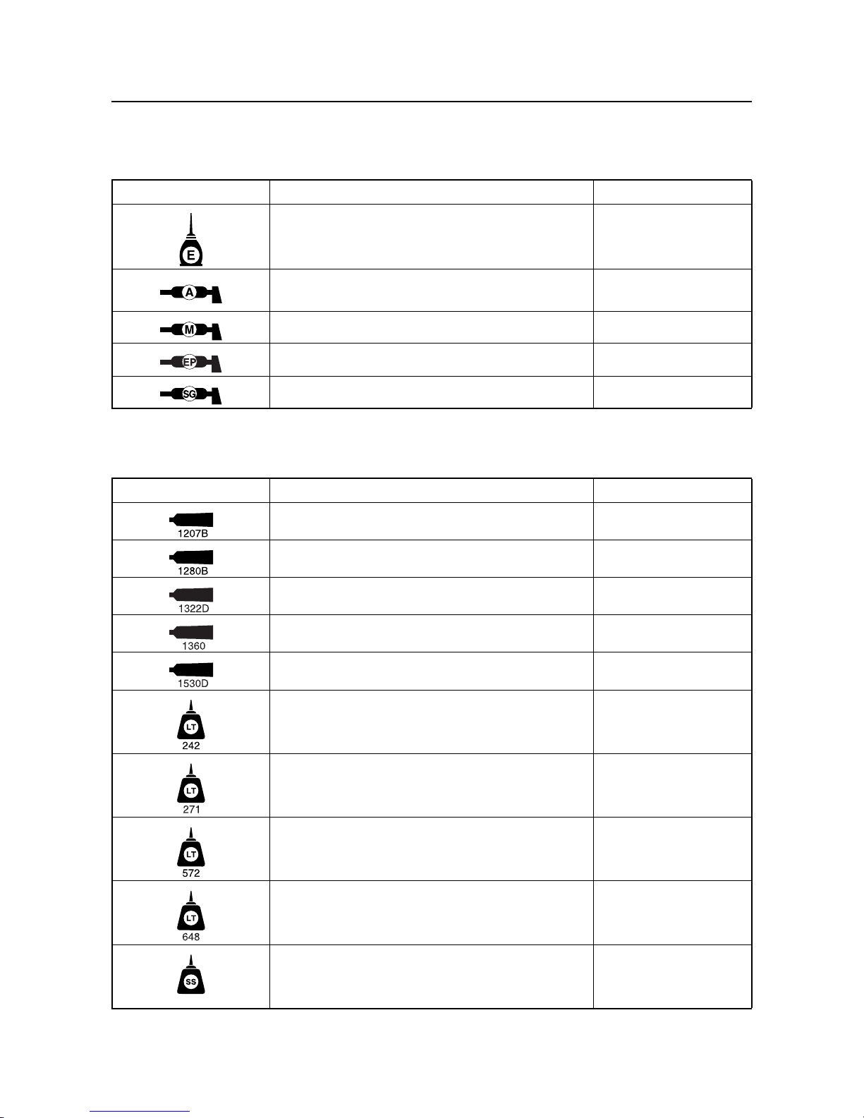
Symbols
Symbols in an exploded diagram or illustration indicate the grade of lubricant and the lubrication points.
Symbols in an exploded diagram or illustration indicate the type of adhesive, sealant, or thread locking
agent and the application points.
Symbol Name Application
YAMALUBE 4W or Yamaha 4-stroke motor oil Lubricant
Water resistant grease
(YAMALUBE MARINE GREASE)
Lubricant
Molybdenum disulfide grease Lubricant
Epnoc grease AP#0 Lubricant
Silicone grease Lubricant
Symbol Name Application
ThreeBond 1207B Sealant
ThreeBond 1280B Sealant
ThreeBond 1322D Thread locking agent
ThreeBond 1360 Thread locking agent
ThreeBond 1530D Adhesive
LOCTITE 242 (blue) Thread locking agent
LOCTITE 271 (red) Thread locking agent
LOCTITE 572 (white) Sealant
LOCTITE 648 (green) Thread locking agent
Silicone sealant Sealant
Special service tool
1-9
Special service tool
Special service tools numbered “YB/YM/YS/YU/YW-*****” are distributed by K & L.
Special service tools with Yamaha part numbers (90890-*****) are distributed by the Parts Division.
Special service tool with part number 90890-06884/LIT-YDIS2-01-KT is distributed by the Marine Service Division.
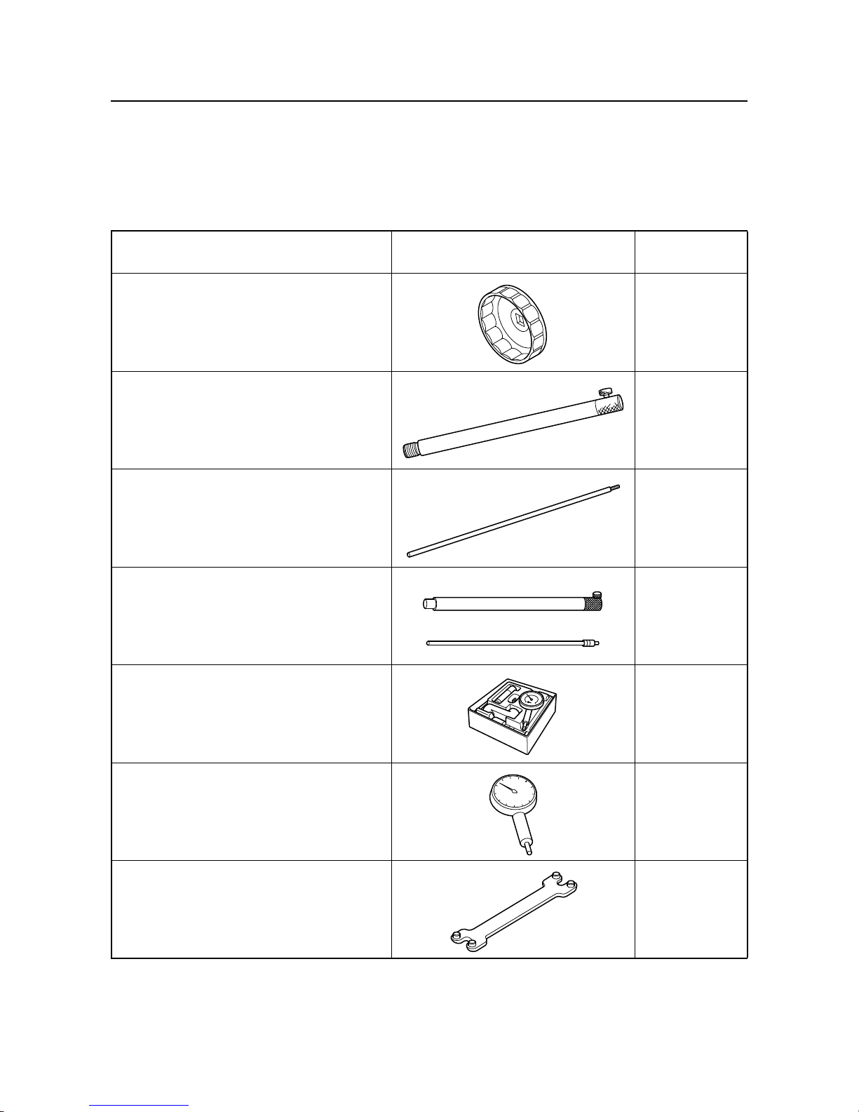
Tool name/Tool No. Illustration
Reference
pages
Oil filter wrench
90890-06830
Oil filter wrench
YB-06830
3-5, 3-5, 5-8,
5-13
Gauge stand
90890-06725
3-12, 5-34,
5-42
Dial gauge needle
90890-06584
3-12, 5-34,
5-42
Dial gauge stand set
YB-06585
3-12, 5-34,
5-42
Dial gauge set
90890-01252
3-12, 5-34,
5-42
Dial indicator gauge
YU-03097
3-12, 5-34,
5-42
Camshaft wrench
90890-06724
Camshaft wrench
YW-06724
3-12, 5-35,
5-38

1-10
Special service tool
Fuel pressure gauge adapter
90890-06946
Fuel pressure gauge adapter
YB-06946
4-3
Fuel pressure gauge
90890-06753
Fuel pressure gauge
YU-03153M
4-3
Compression gauge
90890-03160
Compression gauge
YU-33223
5-1
Compression gauge extension
90890-06563
5-1
Exhaust pipe wrench
90890-06726
Exhaust pipe wrench
YW-06726
5-17, 5-17
Coupler wrench
90890-06729
Coupler wrench
YW-06729
5-29, 5-34,
5-40, 5-42,
5-58, 5-58,
5-66, 5-66,
6-20, 6-22
Tool name/Tool No. Illustration
Reference
pages
YU-33223

Special service tool
1-11
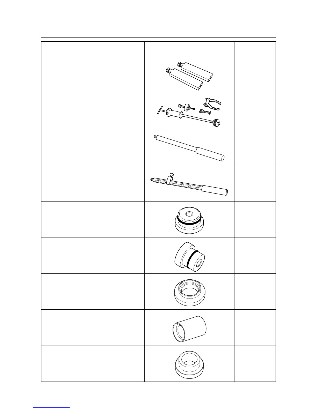
Leakage tester
90890-06840
5-29
Valve spring compressor
90890-04019
Valve spring compressor
YM-04019
5-47, 5-53
Valve spring compressor attachment
90890-04114
Compressor adapter
YM-04114
5-47, 5-53
Valve guide remover/installer
90890-06801
Valve guide remover
YB-06801
5-49, 5-50
Valve guide installer
90890-06810
Valve guide installer
YB-06810
5-50
Valve guide reamer
90890-06804
Valve guide reamer
YM-01196
5-50
Valve lapper
90890-04101
Valve lapping tool
YM-A8998
5-50, 5-53
Tool name/Tool No. Illustration
Reference
pages

1-12
Special service tool
Valve seat cutter holder
90890-06812
5-51
Valve seat cutter 30°
90890-06720
5-51
Valve seat cutter 45°
90890-06325
5-51
Valve seat cutter 60°
90890-06324
5-51
Valve seat cutter 30°
90890-06818
5-51
Valve seat cutter 45°
90890-06555
5-51
Valve seat cutter 60°
90890-06323
5-51
Neway valve seat kit
YB-91044
5-51
Crankshaft holder
90890-06732
Crankshaft holder
YW-06562
5-58, 5-59,
5-63, 5-64,
5-64, 5-65,
5-66
Tool name/Tool No. Illustration
Reference
pages

Special service tool
1-13
Shaft holder
90890-06721
Shaft holder
YW-06721
5-59, 5-59,
5-63, 5-64,
5-64, 5-65,
5-65
Drive handle
90890-06722
Drive handle
YW-06722
5-59, 5-59,
5-63, 5-64,
5-65, 5-65
Flywheel puller
90890-06723
Flywheel puller
YW-06723
5-60
Rotor puller
90890-01080
Stator rotor puller
YM-01080-A
5-60
Sheave holder
90890-01701
Primary sheave holder
YS-01880-A
5-60, 5-62
Driver rod LS
90890-06606
5-60, 5-61
Bearing outer race attachment
90890-06627
5-60
Driver handle (small)
YB-06229
5-60
Bearing and seal installer
YW-06356
5-60
Tool name/Tool No. Illustration
Reference
pages

1-14
Special service tool
Ball bearing attachment
90890-06657
5-61
Driver handle (large)
YB-06071
5-61, 5-61,
6-12
Forward gear outer race installer
YB-41446
5-61
Bearing pressure C
90890-02393
5-61
Forward bearing race installer
YB-06258
5-61
Piston ring compressor
90890-05158
Piston ring compressor
YM-08037
5-86
Drive shaft holder 6
90890-06520
Driveshaft holder
YB-06201
6-11, 6-11,
6-14, 6-14
Stopper guide plate
90890-06501
6-11, 6-12,
6-20
Bearing puller assembly
90890-06535
6-11, 6-12,
6-20
Tool name/Tool No. Illustration
Reference
pages
C
Special service tool
1-15
Stopper guide stand
90890-06538
6-11, 6-12,
6-20
Slide hammer
YB-06096
6-11, 6-12,
6-20
Driver rod L3
90890-06652
6-12
Driver rod SL
90890-06602
6-12
Needle bearing attachment
90890-06609
6-12
Driveshaft needle bearing installer and remover
YB-06194
6-12
Oil seal installer attachment
90890-06733
6-13
Oil seal installer attachment
YW-06628
6-13
Bearing attachment
90890-06728
Bearing attachment
YW-06728
6-13, 6-13,
6-13, 6-21,
6-22
Tool name/Tool No. Illustration
Reference
pages

1-16
Special service tool
Shaft holder
90890-06730
Shaft holder
YW-06730
6-20, 6-22
Bearing puller legs
YB-06523
6-20
Needle bearing attachment
90890-06654
6-21, 6-21,
6-21
Needle bearing installer
YB-06434
6-21, 6-21,
6-21
Bearing attachment
90890-06727
Bearing attachment
YW-06727
6-22, 6-22
YDIS2 Hardware Kit
90890-06884
YDIS2 Hardware Kit
LIT-YDIS2-01-KT
7-9, 9-1
Digital circuit tester
90890-03243
Digital multimeter
YU-34899-A
7-10
Tool name/Tool No. Illustration
Reference
pages

Special service tool
1-17
Peak voltage adapter B
90890-03172
Peak volt adapter
YU-39991
7-10
Ignition checker (Spark gap tester)
90890-06754
Spark checker
YM-34487
7-11
Test harness (2 pins)
90890-06851
7-12
Test harness (3 pins)
90890-06870
Test harness (3 pins)
YB-06870
7-13
Test harness (2 pins)
90890-06850
Test harness (2 pins)
YW-06850
7-13
Vacuum/pressure pump gauge set
90890-06945
Pressure/vacuum tester
YB-35956-B
7-15, 7-18
Test harness (3 pins)
90890-06877
Test harness (3 pins)
YB-06877
7-26
Tool name/Tool No. Illustration
Reference
pages

1-18
Special service tool
Throttle sensor adjusting lead FWY–3
90890-06857
Test harness (3 pins)
YB-06857
7-27
Tool name/Tool No. Illustration
Reference
pages

Model feature
1-19
Model feature
General feature
The F2W features a hull and deck that are based on those of the F2X and is equipped with an 1812
cm³ engine.
While retaining the stability and comfort of the F2X, the acceleration performance and maximum speed
have been improved by increasing the output of the engine.
The 6EW engine is based on the 6CN engine and the size and weight of the fuse box have been reduced.
a. Power unit
• 4-stroke, L4, DOHC, 16-valve, 1812 cm³ engine with electronic fuel injection
• Single throttle body
• 4-in-1 exhaust system
• Wet sump lubrication
b. Jet pump
• Stainless steel, 3-blade, ø155 mm, 15.6°
pitched impeller
• Impeller turning direction: counterclockwise
(when viewed from the stern)
• Aluminum jet thrust nozzle
• RiDE system
c. Electrical
• Electronic control throttle valve system
• In-tank fuel pump module
• Multifunction meter
•L-MODE
•OTS
• Self-diagnosis system with YDIS (version
2.20)
d. Deck and hull
• V-shaped hull
• 2 seat types (different shapes according to
the model)
• Separate front and rear seats
• Reboarding step for easier reboarding (VXR)
• Easy handgrip position
• Large-chine hull
• NanoXcel hull, NanoXcel deck
d
c
b
a

1-20
Model feature
Model equipment comparison table
: Equipped
—: Not equipped
Model VXS VXR
Total length 3.34 m (131.5 in) 3.35 m (131.9 in)
Width 1220 mm (48.0 in)
Dry weight 347 kg (765 lb) 348 kg (767 lb)
Reboarding step “1” —
Front seat “2” Normal seat Cruiser seat
A
B
2
2
1
A. VXS
B. VXR

Technical tips
1-21
Technical tips
Engine control
The ECM controls ignition timing and fuel injection with information received from the sensors and
switches installed on the engine as well as utilizing the base map saved in the ECM.
Part name Function
1 TPS Detects the opening angle of the ETV.
2 Cam position sensor Detects the rotational position of the camshaft.
3 Slant detection switch Detects whether the watercraft is capsized.
4ECM
Properly controls ignition timing, fuel injection timing and volume, opening angle of the ETV, and fail-safe function with information received from the sensors and switches.
5 Thermo sensor Detects the temperature of the exhaust cooling water.
6 Oil pressure switch Detects the pressure of the engine oil.
7 Thermo switch Detects engine overheating.
8
Intake air temperature sensor
Detects the temperature of the intake air.
9 Intake air pressure sensor Detects the pressure of the intake air.
10 Engine temperature sensor Detects the temperature of the cylinder block.
11 Pickup coil Detects the crankshaft angle.
12 RPS Detects the opening angle of the RiDE lever.
11
7
8
2
5
10
9
6
1
3
4
14
12
13

1-22
Technical tips
13 APS Detects the opening angle of the throttle lever.
14 Steering sensor
Detects when the handlebar is turned all the way to the right or
left.
Part name Function

Technical tips
1-23
RiDE system
Unlike previous systems with mechanical shifting and Q.S.T.S., the RiDE motor is driven through electric signals in order to conduct shifting and trim operations.
With electrical operation, conventional cables are not used. By using the RiDE lever and electric trim
switch unit incorporated into the left handlebar switch, shifting and trim operations are easy to control.
The number of parts has been reduced, and serviceability has improved.
The trim function drives the RiDE motor through the electric trim switch in order to move the nozzle.
The trim position is sent to the ECM in order to display the trim angle on the multifunction meter.
The shift function transfers the RiDE lever opening angle into electric signals and then delivers the signals to the ECM. The ECM controls the engine based on the RiDE lever signals, shift position, and engine status, and sends a shift request to the RiDE motor.
When changing the shift, the reverse gate operates after the engine speed has dropped and the water
jet stream intensity has been reduced. This reduces the strain on the reverse gate and allows for
smooth shifting.
B
3
11
13
1
89
2
3
10
12
C
D
7
5
4
6
7
A
A. Q.S.T.S. models
B. RiDE models
C. Mechanical link
D. Electrical signal
1. Shift lever
2. Shift cable
3. Reverse gate
4. Q.S.T.S. selector
5. Q.S.T.S. cable
6. Q.S.T.S. converter
7. Jet thrust nozzle
8. RiDE lever
9. ECM
10. SCU
11. Shift rod
12. Electric trim switch
13. Trim rod
1-24
Technical tips
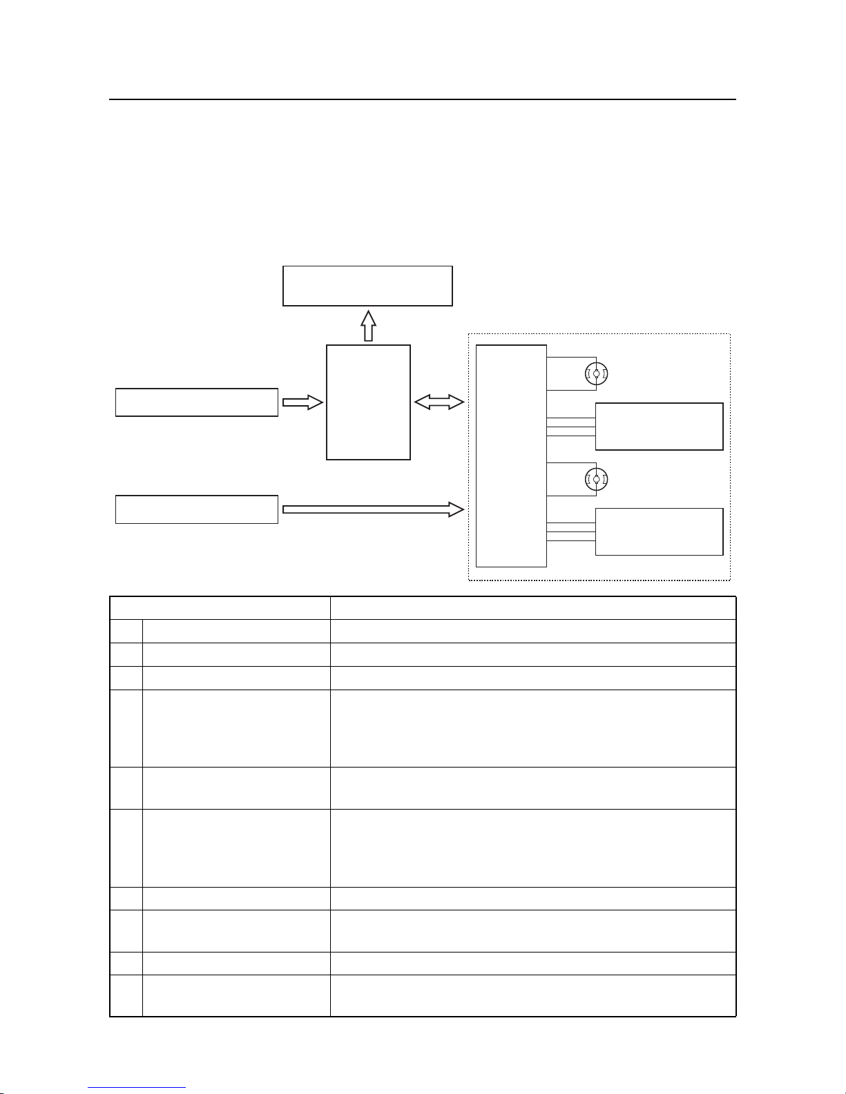
RiDE motor
The RiDE lever employs the same part used for the throttle lever that incorporates the APS. An RPS
(RiDE position sensor) is built into the RiDE lever.
The RiDE motor is an assembly part that includes the shift motor and trim motor, a shift position sensor
that detects the position of each motor, the trim position sensor, and a built-in SCU to control each motor.
This system has sensors, and also has a fail-safe function.
The ECM and SCU use CAN to deliver shift request, shift position, and trim position information.
Part name Function
1 RPS Detects the RiDE lever angle.
2 Electric trim switch Drives the trim motor.
3 Multifunction meter Displays information on shift position and trim position.
4ECM
• Controls the engine operation based on signals transmitted
by each sensor and switch, and sends signals to SCU.
• Sends information on shift position and trim position to the
multifunction meter.
5RiDE motor
An assembly that incorporates SCU, shift motor, SPS, trim motor, and trim position sensor.
6SCU
Shift control: Transmits a shift position signal to the ECM and
drives the shift motor based on the shift request from the ECM.
Trim control: Controls the trim motor based on the signal from
the trim switch and sends trim position information to the ECM.
7 Shift motor Switches the reverse gate angle.
8 Shift position sensor
Detects the shift position based on the rotation angle of the
shift motor.
9 Trim motor Switches the angle of jet thrust nozzle.
10 Trim position sensor
Detects the trim position based on the rotation angle of the trim
motor.
7. Shift motor
5. RiDE motor
9. Trim motor
4. ECM
6. SCU
10. Trim position
sensor
8. Shift position
sensor
1. RPS
2. Electric trim switch
3. Multifunction meter

Technical tips
1-25
ETV system
The F2W is equipped with the same throttle lever as that of the F2S.
The throttle lever has an APS which senses the degree of throttle opening and converts the status into
electronic signals, delivering the information to the ECM. The ECM controls the ETV based on the input
signals of the APS.
Employing the APS in the throttle lever has eliminated the need for throttle cables, reducing the number
of parts used, thereby improving throttle response and serviceability.
The throttle lever has 2 sensors as per the previous APS, the APS 1 and APS 2, which mutually diagnose any failures each system may encounter.
The APS full-close switch detects the fully closed throttle lever position.
A
3
B
1
2
4
5
6
4
5
APS 1
APS 2
b. Ground
5 V
b. Ground
5 V
b. Ground
APS 1
a. APS full close
switch
5 V
5 V
b. Ground
APS 2
5 V
b. Ground
C
D
A. Previous ETV system
B. New ETV system
C. Mechanical link
D. Electrical signal
1. Throttle lever
2. Throttle cable
3. APS
4. ECM
5. ETV
6. Electric throttle without wire cable
a. APS full-close switch
b. Ground
 Loading...