

Yamaha VMX12N, VMX12NC Owner's Manual

EA”00002
INTRODUCTION
Congratulations on your purchase of the Yamaha VMX12/VMX12C. This model is
the result of Yamaha’s vast experience in the production of fine sporting, touring, and
pacesetting racing machines. It represents the high degree of craftsmanship and
reliability that have made Yamaha a leader in these fields.
This manual will give you an understanding of the operation, inspection, and basic
maintenance of this motorcycle. If you have any questions concerning the operation
or maintenance of your motorcycle, please consult a Yamaha dealer.
The design and manufacture of this Yamaha motorcycle fully comply with the emis-
sions standards for clean air applicable at the date of manufacture. Yamaha has met
these standards without reducing the performance or economy of operation of the
motorcycle. To maintain these high standards, it is important that you and your
Yamaha dealer pay close attention to the recommended maintenance schedules and
operating instructions contained within this manual.
..“.
A
SAFETY INFORMATION
EAU00014
MOTORCYCLES ARE SINGLE TRACK VEHICLES. THEIR SAFE USE AND OPERATION ARE
DEPENDENT UPON THE USE OF PROPER RIDING TECHNIQUES AS WELL AS THE EXPERTISE
OF THE OPERATOR. EVERY OPERATOR SHOULD KNOW THE FOLLOWING REQUIREMENTS
BEFORE RIDING THIS MOTORCYCLE.
HE OR SHE SHOULD:
1. OBTAIN THOROUGH INSTRUCTIONS FROM A COMPETENT SOURCE ON ALL ASPECTS OF
MOTORCYCLE OPERATION.
2. OBSERVE THE WARNINGS AND MAINTENANCE REQUIREMENTS IN THE OWNER’S MANUAL.
3. OBTAIN QUALIFIED TRAINING IN SAFE AND PROPER RIDING TECHNIQUES.
4. OBTAIN PROFESSIONAL TECHNICAL SERVICE AS INDICATED BY THE OWNER’S MANUAL
AND/OR WHEN MADE NECESSARY BY MECHANICAL CONDITIONS.
Safe riding
1. Always make pre-operation checks. Careful checks may help prevent an accident.
2. This motorcycle is designed to carry the operator and a passenger.
3. The failure of motorists to detect and recognize motorcycles in traffic is the predominating cause of
automobile/motorcycle accidents. Many accidents have been caused by an automobile driver who
did not see the motorcycle. Making yourself conspicuous appears to be very effective in reducing the
chance of this type of accident.
Therefore:
a.
Wear a brightly colored jacket.
b.
Use extra caution when you are approaching and passing through intersections, since intersec-
tions are the most likely places for motorcycle accidents to occur.
c.
Ride where other motorists can see you. Avoid riding in another motorist’s blind spot.
l-l

A
SAFETY INFORMATION
4. Many accidents involve inexperienced operators. In fact, many operators who have been involved in
accidents do not even have a current motorcycle license.
a.
Make sure that you are qualified and that you only lend your motorcycle to other qualified opera-
tors.
b.
Know your skills and limits. Staying within your limits may help you to avoid an accident.
c.
We recommend that you practice riding your motorcycle where there is no traffic until you have
become thoroughly familiar with the motorcycle and all of its controls.
5. Many accidents have been caused by error of the motorcycle operator. A typical error made by the
operator is veering wide on a turn due to EXCESSIVE SPEED or undercornering (insufficient lean
angle for the speed).
a.
Always obey the speed limit and never travel faster than warranted by road and traffic conditions.
b.
Always signal before turning or changing lanes. Make sure that other motorists can see you.
6. The posture of the operator and passenger is important for proper control.
a.
The operator should keep both hands on the handlebar and both feet on the operator footrests
during operation to maintain control of the motorcycle.
b.
The passenger should always hold onto the operator, the seat strap or grab bar, if equipped, with
both hands and keep both feet on the passenger footrests.
c.
Never carry a passenger unless he or she can firmly place both feet on the passenger footrests.
7.
Never ride under the influence of alcohol or other drugs.
8. This motorcycle is designed for on-road use only. It is not suitable for off-road use.
l-2

A
SAFETY INFORMATION
Protective apparel
The majority of fatalities from motorcycle accidents are the result of head injuries. The use of a safety
helmet is the single most critical factor in the prevention or reduction of head injuries.
1. Always wear an approved helmet.
2.
Wear a face shield or goggles. Wind in your unprotected eyes could contribute to an impairment of vision that could delay seeing a hazard.
3. The use of a jacket, heavy boots, trousers, gloves, etc., is effective in preventing or reducing abrasions or lacerations.
4.
Never wear loose-fitting clothes, otherwise they could catch on the control levers, footrests, or wheels
and cause injury or an accident.
5.
Never touch the engine or exhaust system during or after operation. They become very hot and can
cause burns. Always wear protective clothing that covers your legs, ankles, and feet.
6. A passenger should also observe the above precautions.
Modifications
Modifications made to this motorcycle not approved by Yamaha, or the removal of original equipment,
may render the motorcycle unsafe for use and may cause severe personal injury. Modifications may
also make your motorcycle illegal to use.
Loading and accessories
Adding accessories or cargo to your motorcycle can adversely affect stability and handling if the
weight distribution of the motorcycle is changed. To avoid the possibility of an accident, use extreme
caution when adding cargo or accessories to your motorcycle. Use extra care when riding a
motorcycle that has added cargo or accessories. Here are some general guidelines to follow if loading
cargo or adding accessories to your motorcycle:
l-3
&
SAFETY INFORMATION
Loading
The total weight of the operator, passenger, accessories and cargo must not exceed the maximum
load limit of VMX12: 476 lb (216 kg) / VMX12C: 474 lb (215 kg). When loading within this weight limit,
keep the following in mind:
1. Cargo and accessory weight should be kept as low and close to the motorcycle as possible. Make
sure to distribute the weight as evenly as possible on both sides of the motorcycle to minimize imbal-
ance or instability.
2.
Shifting weights can create a sudden imbalance. Make sure that accessories and cargo are securely
attached to the motorcycle before riding. Check accessory mounts and cargo restraints frequently.
3. Never attach any large or heavy items to the handlebar, front fork, or front fender. These items, in-
cluding such items as sleeping bags, duffel bags, or tents, can create unstable handling or a slow
steering response.
Accessories
Genuine Yamaha accessories have been specifically designed for use on this motorcycle. Since
Yamaha cannot test all other accessories that may be available, you must personally be responsible
for the proper selection, installation and use of non-Yamaha accessories. Use extreme caution when
selecting and installing any accessories.
Keep the following guidelines in mind, as well as those provided under “Loading” when mounting
accessories.
1.
Never install accessories or carry cargo that would impair the performance of your motorcycle. Carefully inspect the accessory before using it to make sure that it does not in any way reduce ground
clearance or cornering clearance, limit suspension travel, steering travel or control operation, or ob-
scure lights or reflectors.
l-4
A
SAFETY INFORMATION
2.
a.
Accessories fitted to the handlebar or the front fork area can create instability due to improper
weight distribution or aerodynamic changes. If accessories are added to the handlebar or front
fork area, they must be as lightweight as possible and should be kept to a minimum.
b.
Bulky or large accessories may seriously affect the stability of the motorcycle due to aerodynamic
effects. Wind may attempt to lift the motorcycle, or the motorcycle may become unstable in cross
winds. These accessories may also cause instability when passing or being passed by large ve-
hicles.
c.
Certain accessories can displace the operator from his or her normal riding position. This improper position limits the freedom of movement of the operator and may limit control ability, therefore,
such accessories are not recommended.
Use caution when adding electrical accessories. If electrical accessories exceed the capacity of the
motorcycle’s electrical system, an electric failure could result, which could cause a dangerous loss of
lights or engine power.
Gasoline and exhaust gas
1. GASOLINE IS HIGHLY FLAMMABLE:
a.
Always turn the engine off when refueling.
b.
Take care not to spill any gasoline on the engine or exhaust system when refueling.
c.
Never refuel while smoking or in the vicinity of an open flame.
2.
Never start the engine or let it run for any length of time in a closed area. The exhaust fumes are poisonous and may cause loss of consciousness and death within a short time. Always operate your
motorcycle in an area that has adequate ventilation.
3. Always turn the engine off before leaving the motorcycle unattended and remove the key from the
main switch. When parking the motorcycle, note the following:
l-5

A
SAFETY INFORMATION
a.
The engine and exhaust system may be hot, therefore, park the motorcycle in a place where pedestrians or children are not likely to touch these hot areas.
b.
Do not park the motorcycle on a slope or soft ground, otherwise it may fall over.
c.
Do not park the motorcycle near a flammable source (e.g., a kerosene heater, or near an open
flame), otherwise it could catch fire.
4. When transporting the motorcycle in another vehicle, make sure that it is kept upright. If the motorcycle should lean over, gasoline may leak out of the carburetor or fuel tank.
5. If you should swallow any gasoline, inhale a lot of gasoline vapor, or allow gasoline to get into your
eyes, see your doctor immediately. If any gasoline spills on your skin or clothing, immediately wash
the affected area with soap and water and change your clothes.
1-6
A
SAFETY INFORMATION
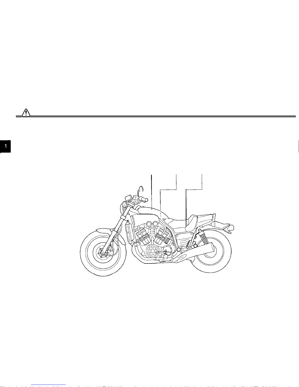
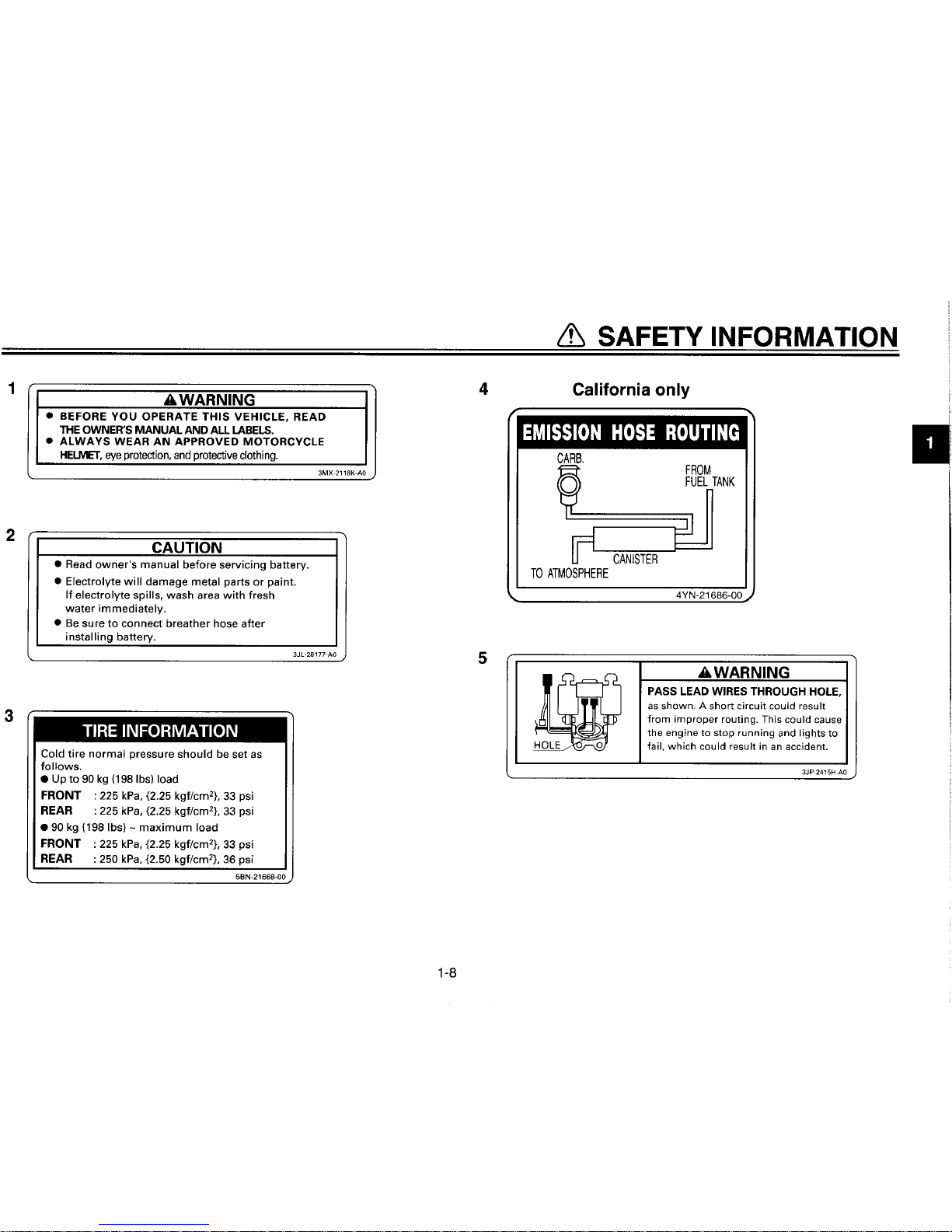
Location of important labels
u
Please read the following important labels carefully before operating this motorcycle.
1
2,3,4
5
-A
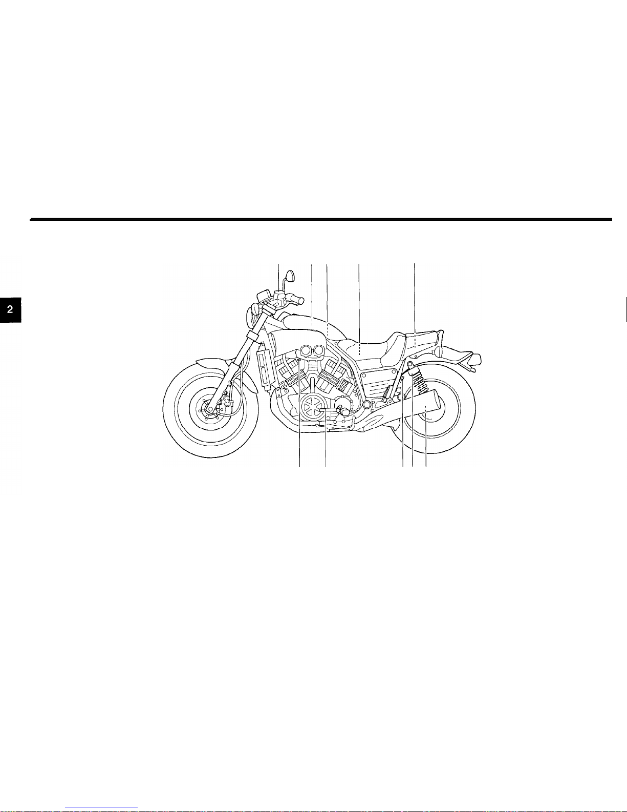
DESCRIPTION
Left view
1
2
3 4
5
1. Clutch master cylinder reservoir
2. Air filter element
3.
Fuse box
4. Main fuse box
5. Owner’s tool kit
6.
Rear shock absorber spring preload
adjusting ring
10 9 87 6
(page 6-29)
7. Rear shock absorber damping force
(page 6-21)
adjusting knob
(page 3-13)
(page 6-38)
8. Helmet holder
(page 3-10)
(page 6-38)
9. Shift pedal
(page 3-5)
(page 6-l
)
I0.
Starter (choke) lever
(Page 3-8)
(page 3-13)
2-1
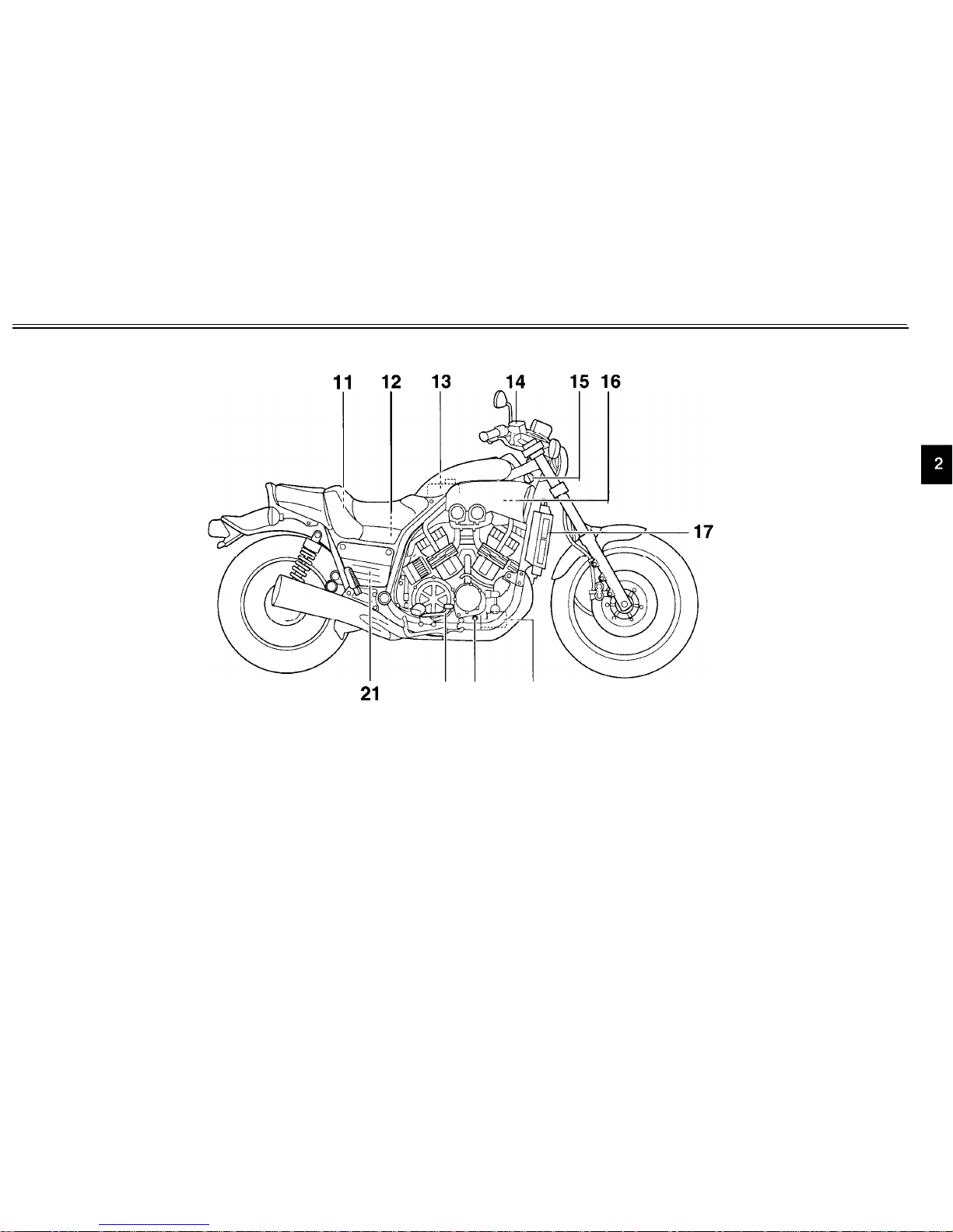
DESCRIPTION
Right view
11. Fuel tank cap
12.
Battery
13.
Coolant reservoir
14. Front brake master cylinder reservoir
15.
Main switch
16.
Radiator
cap
17.
Radiator
18. Engine oil filter cartridge
19. Engine oil level check window
20. Brake pedal
21. Rear brake fluid reservoir
20 19
18
(page
3-6)
(page 6-35)
(page 6-16)
(page 6-29)
(page 3-1)
)
(page 6-18)
(page 6-18)
(page 6-12)
(page 6-11)
(page 3-6)
(page 6-29)
2-2

DESCRIPTION
Controls and instruments
1.
Clutch lever
2. Left handlebar switches
3.
Speedometer
unit
4. Right handlebar switches
5.
Brake lever
6.
Throttle grip
7.
Tachometer
8. Coolant temperature gauge
8 7
6
(page 3-5)
(page 3-3)
(page 3-2)
(page 3-4)
(page 3-5)
(page 6-22)
(page 3-3)
(page 3-3)
2-3
INSTRUMENT AND CONTROL FUNCTIONS
EAU00027
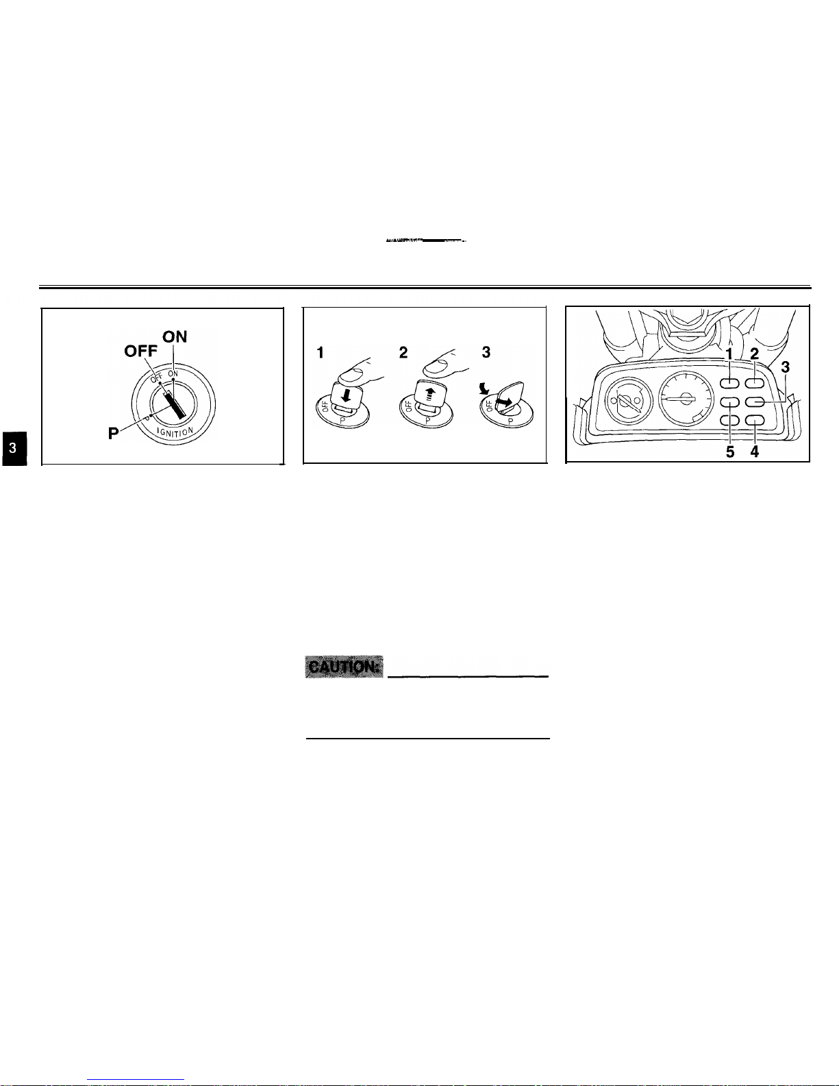
Main switch
EAUO0028
The main switch controls the ignition
and lighting systems. The various main
switch positions are described below.
EAU00032
ON
All electrical systems are supplied with
power, the headlight, meter lighting,
taillight and front position lights come
on, and the engine can be started. The
key cannot be removed.
EAU00038
OFF
All electrical systems are off. The key
can be removed.
1. Push.
2. Release.
3. Turn
P (Parking)
The meter light, taillight and position
lights are on, but all other electrical systems are off. The key can be removed.
The key must be pushed in from the
“OFF” position to be turned to “P”.
ECA00043
Do not use the parking position for
an extended length of time, otherwise the battery may discharge.
1. Neutral indicator light 'NEUTRAL’
2. Turn signal indicator light 'TURN'
3. Fuel level warning light 'FUEL'
4. High beam indicator light 'HIGH BEAM'
5. Oil level warning light 'OIL LEVEL'
EAU03034
Indicator and warning lights
EAU00062
Neutral indicator light “NEUTRAL”
This indicator light comes on when the
transmission is in the neutral position.
EAU00059
Turn signal indicator light “TURN”
This indicator light flashes when the
turn signal switch is pushed to the left
or right.
3-1
INSTRUMENT AND CONTROL FUNCTIONS
EAU03365 EAU03366
Fuel level warning light “FUEL”
This warning light comes on when the
fuel level drops below approximately
3 L (0.7 Imp gal, 0.8 US gal). When this
occurs, refuel as soon as possible.
The electrical circuit of the warning light
can be checked according to the fol-
lowing procedure.
1. Turn the key to “ON”.
2. If the warning light does not come
on, have a Yamaha dealer check
the electrical circuit.
Oil level warning light “OIL LEVEL”
This warning light comes on when the
engine oil level is low.
The electrical circuit of the warning light
can be checked according to the following procedure.
1. Turn the key to “ON”.
2. If the warning light does not come
on, have a Yamaha dealer check
the electrical circuit.
NOTE:
EAU00064
High beam indicator light
“HIGH BEAM”
This indicator light comes on when the
high beam of the headlight is switched
on.
Even if the oil level is sufficient, the
warning light may flicker when riding on
a slope or during sudden acceleration
or deceleration, but this is not a malfunction.
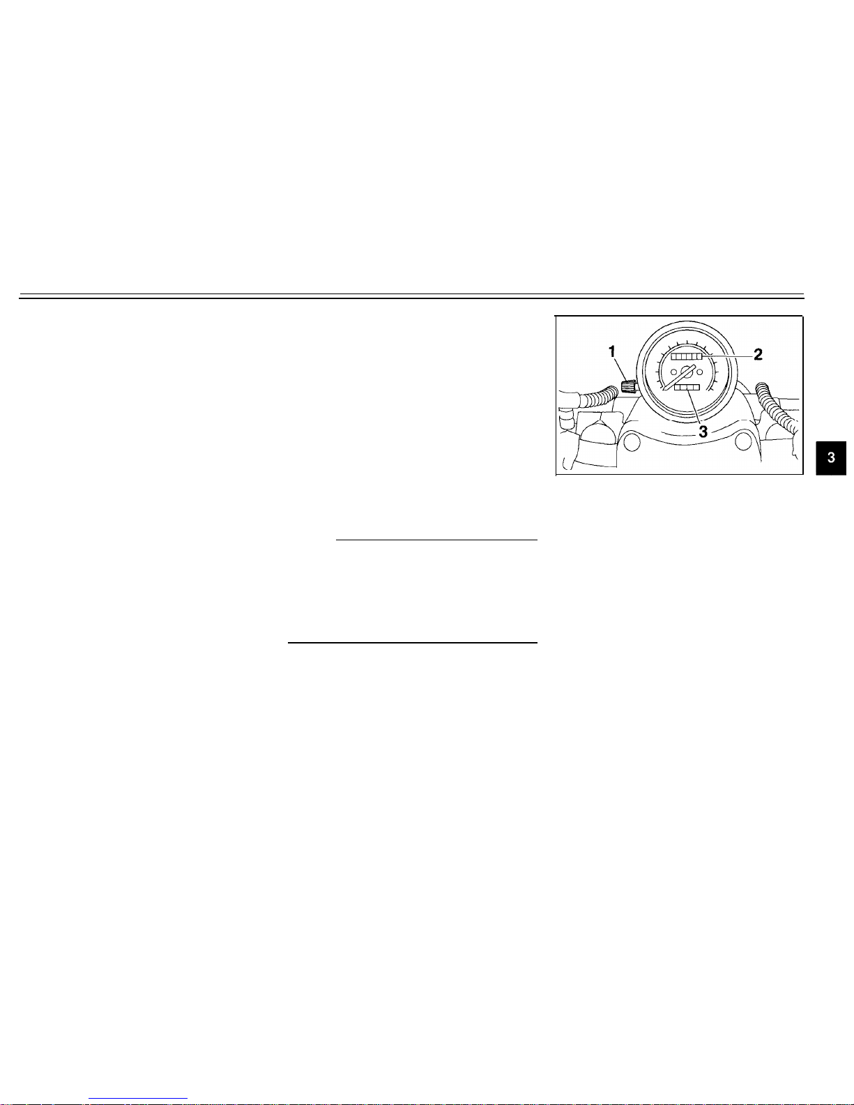
1. Tripmeter reset knob
2. Odometer
3. Tripmeter
Speedometer unit
EAU00095
The speedometer unit is equipped with
a speedometer, an odometer and a
tripmeter. The speedometer shows
riding speed. The odometer shows the
total distance traveled. The tripmeter
shows the distance traveled since it
was last set to zero with the reset knob.
The tripmeter can be used to estimate
the distance that can be traveled with a
full tank of fuel. This information will en-
able you to plan future fuel stops.
3-2
INSTRUMENT AND CONTROL FUNCTIONS
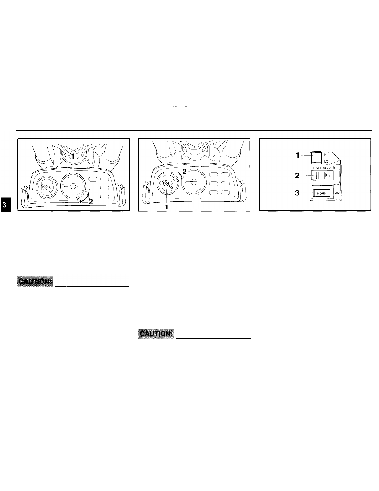
1
1. Tachometer
2. Red zone
Tachometer
The electric tachometer allows the rider
to monitor the engine speed and keep it
within the ideal power range.
EC000003
Do not operate the engine in the
tachometer red zone.
Red zone: 8,500 r/min and above
1. Coolant temperature gauge
2. Red zone
Coolant temperature gauge
With the key in the “ON” position, the
coolant temperature gauge indicates
the temperature of the coolant. The
coolant temperature varies with changes in the weather and engine load. If
the needle reaches or enters the red
zone, stop the motorcycle and let the
engine cool. (See page 6-47 for further
instructions.)
EC000002
Do not operate the engine if it is
overheated.
1. Dimmer switch “LIGHTS”
2. Turn signal switch “TURN”
3. Horn switch “HORN”
Handlebar switches
Dimmer switch “LIGHTS”
Set the switch to “HI” for the high beam
and to “LO” for the low beam.
Turn signal switch “TURN”
To signal a right-hand turn, push this
switch to the right. To signal a left-hand
turn, push the switch to the left. When
released, the switch returns to the cen-
ter position.
3-3

INSTRUMENT AND CONTROL FUNCTIONS
Since this model is equipped with a
self-canceling system, the turn signal
lights will self-cancel after the motorcycle has traveled both about 150 m
(490 ft) and for approximately 15 seconds. However, the turn signal lights
can also be canceled manually by
pushing the switch in after it has returned to the center position.
1.
Engine stop switch “ENGINE STOP”
NOTE:
2. Fuel reserve switch “FUEL”
The self-canceling system only oper-
3. Start switch “START”
ates when the motorcycle is moving, so
that the turn signal lights will not
self-
Engine stop switch “ENGINE STOP”
cancel while you are stopped at an
in-
Set this switch to “OFF” to stop the en-
tersection.
gine in case of an emergency, such as
when the motorcycle overturns or
when the throttle cable is stuck.
30
Horn switch “HORN”
Press this switch to sound the horn.
EAU01653
Fuel reserve switch “FUEL”
During normal operation, this switch
should be kept in the “ON” position. If
the fuel warning light comes on while
riding, set the switch to “RES”, refuel as
soon as possible, and then set the
switch back to “ON”.
NOTE:
After switching to “RES”, approximately
3 L (0.7 Imp gal, 0.8 US gal) of fuel re-
main in the fuel tank.
Start switch “START”
Push this switch to crank the engine
with the starter.
EC000005
See page 5-1 for starting instruc-
tions prior to starting the engine.
3-4
INSTRUMENT AND CONTROL FUNCTIONS
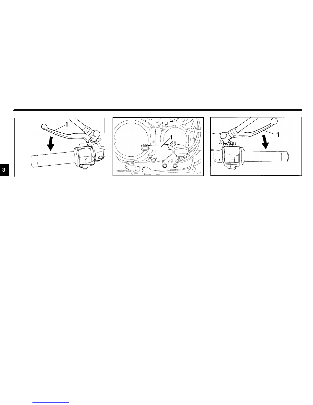
1. Clutch lever
1. Shift pedal
Clutch lever
52
The clutch lever is located at the left
handlebar grip. To disengage the
clutch, pull the lever toward the handlebar grip. To engage the clutch, release
the lever. The lever should be pulled
rapidly and released slowly for smooth
clutch operation.
The clutch lever is equipped with a
clutch switch, which is part of the ignition circuit cut-off system. (See page
3-17 for an explanation of the ignition
circuit cut-off system.)
Shift pedal
EAU00157
The shift pedal is located on the left
side of the engine and is used in com-
bination with the clutch lever when
shifting the gears of the 5-speed con-
stant-mesh transmission equipped on
this motorcycle.
1. Brake lever
Brake lever
The brake lever is located at the right
handlebar grip. To apply the front
brake, pull the lever toward the handlebar grip.
3-5

INSTRUMENT AND CONTROL FUNCTIONS
1. Brake pedal 1. Lever (x 2) 1. Open
62
Brake pedal Fuel tank cap
2. Insert the key into the lock, and
then turn it
1/4
turn clockwise. The
The brake pedal is on the right side of
lock will be released and the fuel
the motorcycle. To apply the rear
To remove the fuel tank cap
brake, press down on the brake pedal.
1. Push the levers on the left and
tank cap can be opened.
right side of the rider seat backrest
as shown and slide the rider seat
backrest forward.
3-6
INSTRUMENT AND CONTROL FUNCTIONS
To install the fuel tank cap
1. Insert the fuel tank cap into the
tank opening with the key inserted
in the lock.
2. Turn the key counterclockwise,
and then remove it.
3. Slide the rider seat backrest rearward and push it down.
NOTE:
The fuel tank cap cannot be installed
unless the key is in the lock. In addition,
the key cannot be removed if the cap is
not properly installed and locked.
EW000024
Make sure that the fuel tank cap is
properly installed before riding.
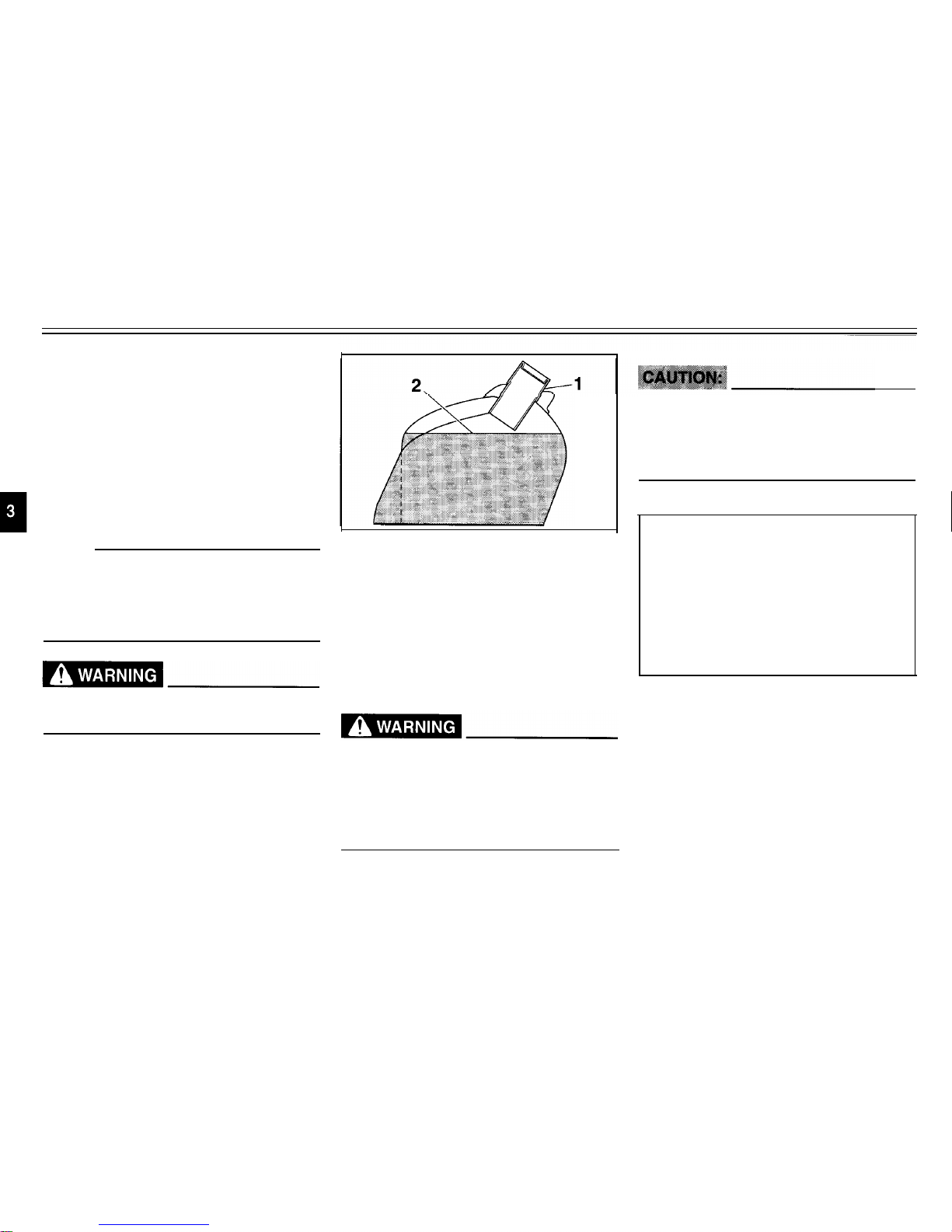
1. Filler tube
2. Fuel level
Fuel
Make sure that there is sufficient fuel in
the tank. Fill the fuel tank to the bottom
of the filler tube as shown in the illustration.
EW000130
l
Do not overfill the fuel tank, oth-
erwise it may overflow when the
fuel warms up and expands.
l Avoid spilling fuel on the hot
engine.
EAU00185
Immediately wipe off spilled fuel
with a clean, dry, soft cloth, since
fuel may deteriorate painted surfaces or plastic parts.
EAU00189
Recommended fuel:
UNLEADED FUEL
Fuel tank capacity:
Total amount:
15 L (3.3 Imp gal, 4.0 US gal)
Reserve amount:
3 L (0.7 Imp gal, 0.8 US gal)
Your Yamaha engine has been designed to use regular unleaded gaso-
line with a pump octane number
[(R+M)/2] of 86 or higher, or a research
octane number of 91 or higher. If
knocking (or pinging) occurs, use a
gasoline of a different brand or premi-
um unleaded fuel. Use of unleaded fuel
will extend spark plug life and reduce
3-7

INSTRUMENT AND CONTROL FUNCTIONS
maintenance costs. If unleaded gaso-
line is not available, then leaded regu-
lar gasoline can be used.
Gasohol
There are two types of gasohol: gasohol containing ethanol and that contain-
ing methanol. Gasohol containing
ethanol can be used if the ethanol content does not exceed 10%. Gasohol
containing methanol is not recom-
mended by Yamaha because it can
cause damage to the fuel system or ve-
hicle performance problems.
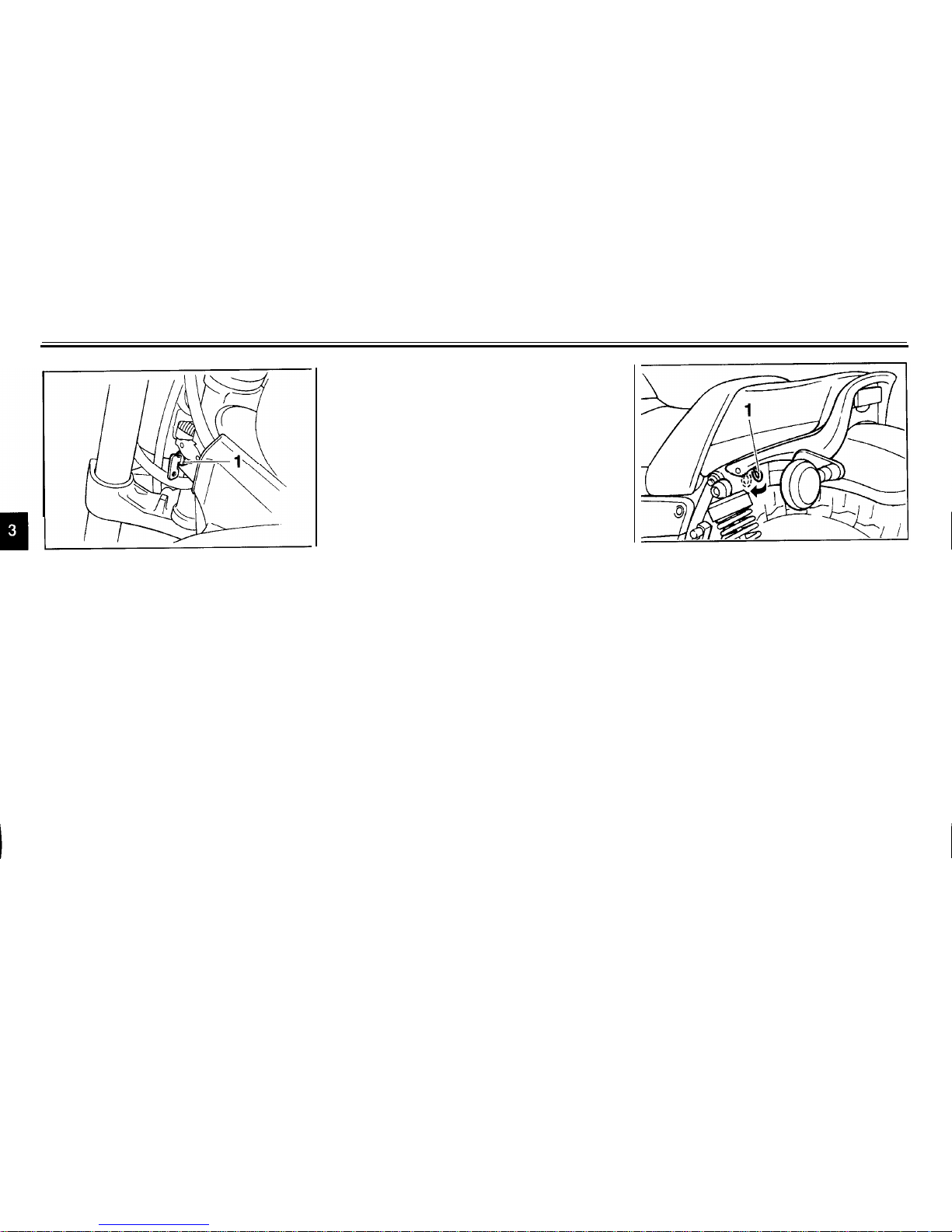
1. Starter (choke) lever
Starter (choke) lever
Starting a cold engine requires a richer
air-fuel mixture, which is supplied by
the starter (choke).
Move the lever in direction a to turn on
the starter (choke).
Move the lever in direction b to turn off
the starter (choke).
3-8
INSTRUMENT AND CONTROL FUNCTIONS
1. Steering lock
Steering lock
EAU03342
To lock the steering
1. Turn the handlebar all the way to
the right.
2. Open the steering lock cover, and
then insert the steering lock key.
3. Turn the key 1/8 turn counter-
clockwise, push it in while turning
the handlebar slightly to the left,
and then turn the key 1/8 turn
clockwise.
4. Check that the steering is locked,
remove the key, and then close
the lock cover.
To unlock the steering
1. Open the steering lock cover, and
then insert the steering lock key.
2. Push the key in, turn it 1/81/8 turn
counterclockwise so that it moves
out, and then release it.
3. Remove the key, and then close
the lock cover.
1. Lever (x 2)
Rider seat
EAU03413
To remove the rider seat
1. Release the rider seat backrest by
pushing the levers on the left and
right side as shown, and then slide
the backrest forward.
3-9

INSTRUMENT AND CONTROL FUNCTIONS
1. Bolt (x 2)
1. Projection
2. Screw (x 2) 2. Seat holder
2. Remove the bolts and screws, and
To install the rider seat
then pull the rider seat off.
1.
Insert the projection on the front of
the rider seat into the seat holder
as shown.
2. Place the rider seat in the original
position, and then tighten the bolts
and screws.
NOTE:
Make sure that the seat is properly secured before riding.
3. Return the rider seat backrest to
the original position.
1. Helmet holder
2. Open
EAU00260
Helmet holder
To open the helmet holder, insert the
key into the lock, and then turn the key
as shown.
To lock the helmet holder, place it in
the original position, and then remove
the key.
EW000030
Never ride with a helmet attached to
the helmet holder, since the helmet
may hit objects, causing loss of
control and possibly an accident.
3-10

INSTRUMENT AND CONTROL FUNCTIONS
EAU03414
Adjusting the front fork
This front fork is equipped with air
valves for adjusting the spring rate.
EW000035
Always adjust both fork legs equal-
ly, otherwise poor handling and loss
of stability may result.
1. Air valve cap
2. Air valve
Adjust the spring rate as follows.
1. Elevate the front wheel by placing
the motorcycle on the centerstand.
NOTE:
When checking and adjusting the air
pressure, there should be no weight on
the front end of the motorcycle.
2. Remove the air valve cap from
each fork leg.
1. Air pressure gauge
3. Check the air pressure in each
fork leg with an air pressure
gauge.
NOTE:
An optional air pressure gauge is available at a Yamaha dealer.
4. To increase the spring rate and
thereby harden the suspension,
increase the air pressure with an
air pump or compressed air. To
decrease the spring rate and
thereby soften the suspension, decrease the air pressure by pushing
each valve stem down.
3-11
INSTRUMENT AND CONTROL FUNCTIONS
Spring rate:
Minimum/standard (soft):
Air pressure =
40 kPa (0.4 kgf/cm², 5.7 psi)
Maximum (hard):
Air pressure =
100 kPa (1.0 kgf/cm², 14 psi)
EC000012
Never exceed the maximum air pressure, otherwise the front fork oil
seals may become damaged.
EWA00037
There must be no difference in air
pressure between the left and right
fork legs, otherwise poor handling
and loss of stability may result.
5. Securely install the air valve caps.
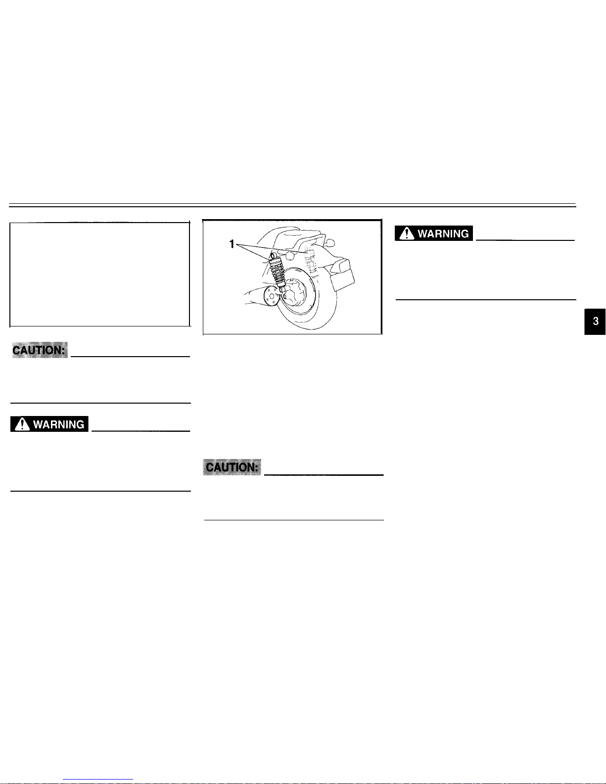
1. Shock absorber assembly (x 2)
Adjusting the shock absorber
assemblies
Both shock absorber assemblies are
equipped with a spring preload adjust-
ing ring and a damping force adjusting
knob.
EC00001 5
Never attempt to turn an adjusting
mechanism beyond the maximum
or minimum settings.
EW000040
Always adjust both shock absorber
assemblies equally, otherwise poor
handling and loss of stability may
result.
3-12
INSTRUMENT AND CONTROL FUNCTIONS
NOTE:
l Align the bottom edge of the ad-
justing ring with the appropriate
setting on the shock absorber.
l
Use the special wrench included in
the owner’s tool kit to make this
adjustment.
Spring preload:
Spring preload
To increase the spring preload and
thereby harden the suspension, turn
the adjusting ring on each shock ab-
sorber assembly in direction a To de-
crease the spring preload and thereby
soften the suspension, turn the adjust-
ing ring on each shock absorber as-
sembly in direction b
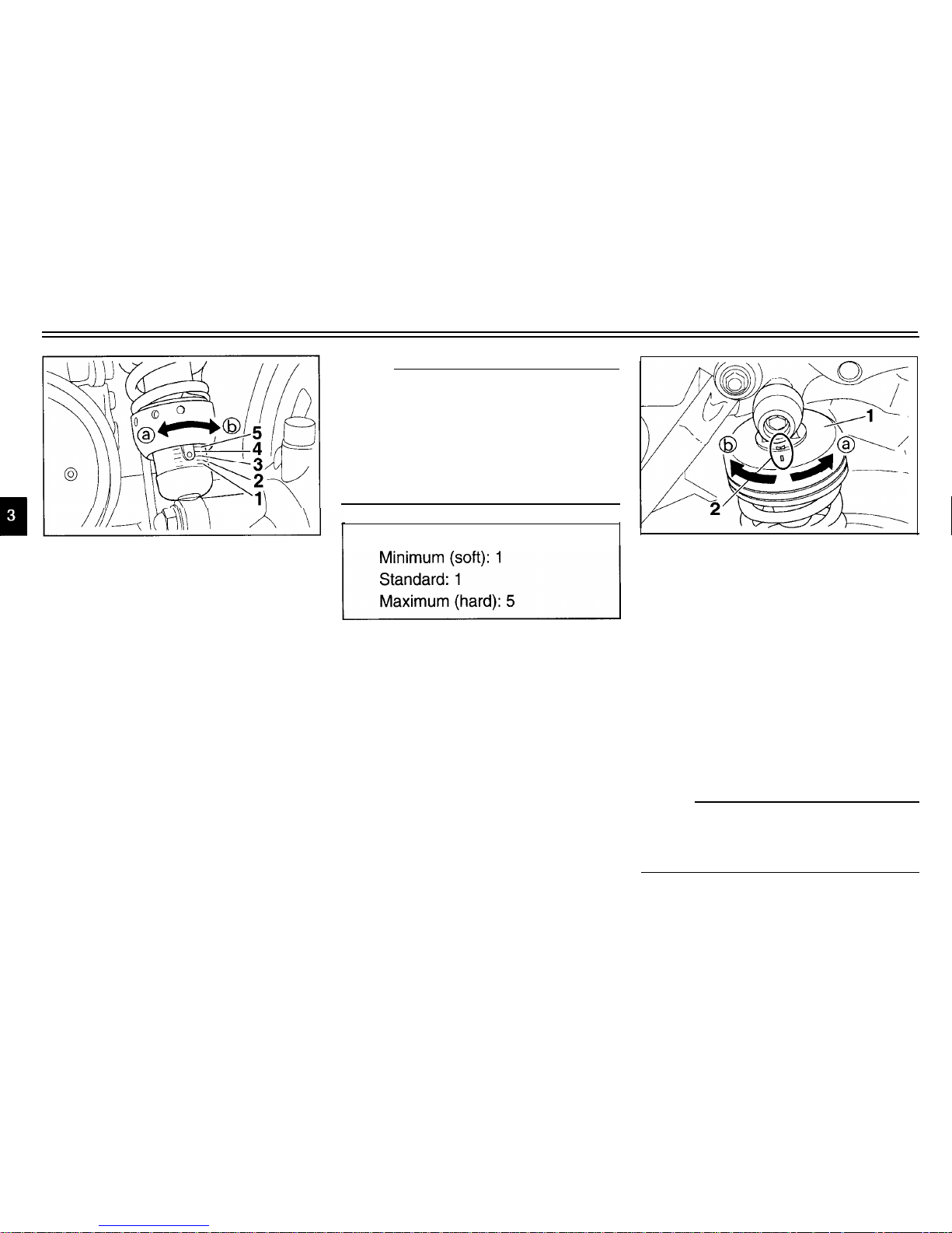
1. Damping force adjusting knob
2. Position indicator
Damping force
To increase the damping force and
thereby harden the damping, turn the
adjusting knob on each shock absorber
assembly in direction a To decrease
the damping force and thereby soften
the damping, turn the adjusting knob
on each shock absorber assembly in
direction
b
NOTE:
Align the appropriate setting on the adjusting knob with the position indicator
on the shock absorber.
3-13
INSTRUMENT AND CONTROL FUNCTIONS
Damping force:
Minimum (soft): 1
Standard: 1
Maximum (hard): 4
3-14

INSTRUMENT AND CONTROL FUNCTIONS
658
Matching the front and rear suspension settings
Use this table as a guide to match the suspension and damping adjustments of the front fork and shock absorber assembly
according to various load conditions.
Load condition
Rider only
With passenger or with
accessories and equipment
Front fork adjustment
Spring preload (air pressure)
40-60 kPa
0.4-0.6
kgf/cm²
5.7-8.5 psi
40-100 kPa
0.4-l.0
kgf/cm²
5.7-14 psi
40-100 kPa
0.4-l.0 kgf/cm²
kgf/c
5.7-14 psi
Shock absorber assembly adjustment
Spring preload Damping force
l-2
l-2
3-5 2-4
With passenger,
accessories and equipment
5
4
EC000015
Never attempt to turn an adjusting mechanism beyond the maximum or minimum settings.
3-15
 Loading...