

Yamaha VMX12 (2001) Service Manual

2001
VMX12
3LRD-AE1
SERVICE MANUAL


EAS00000
VMX12 2001
SERVICE MANUAL
© 2000 by Yamaha Motor Co., Ltd.
First edition, June 2000
All rights reserved.
Any reproduction or unauthorized use
without the written permission of
Yamaha Motor Co., Ltd.
is expressly prohibited.
EAS00002
NOTICE
This manual was produced by the Yamaha Motor Company, Ltd. primarily for use by Yamaha dealers and their qualified mechanics. It is not possible to include all the knowledge of a mechanic in
one manual. Therefore, anyone who uses this book to perform maintenance and repairs on Yamaha
vehicles should have a basic understanding of mechanics and the techniques to repair these types
of vehicles. Repair and maintenance work attempted by anyone without this knowledge is likely to
render the vehicle unsafe and unfit for use.
Yamaha Motor Company, Ltd. is continually striving to improve all of its models. Modifications and
significant changes in specifications or procedures will be forwarded to all authorized Yamaha dealers and will appear in future editions of this manual where applicable.
NOTE:
@
Designs and specifications are subject to change without notice.
@
EAS00004
IMPORTANT MANUAL INFORMATION
Particularly important information is distinguished in this manual by the following.
The Safety Alert Symbol means ATTENTION! BECOME ALERT! YOUR
SAFETY IS INVOLVED!
WARNING
CAUTION:
NOTE:
Failure to follow WARNING instructions could result in severe injury or death to
the motorcycle operator, a bystander or a person checking or repairing the
motorcycle.
A CAUTION indicates special precautions that must be taken to avoid damage
to the motorcycle.
A NOTE provides key information to make procedures easier or clearer.
EAS00007
HOW TO USE THIS MANUAL
This manual is intended as a handy, easy-to-read reference book for the mechanic. Comprehensive
explanations of all installation, removal, disassembly, assembly, repair and check procedures are
laid out with the individual steps in sequential order.
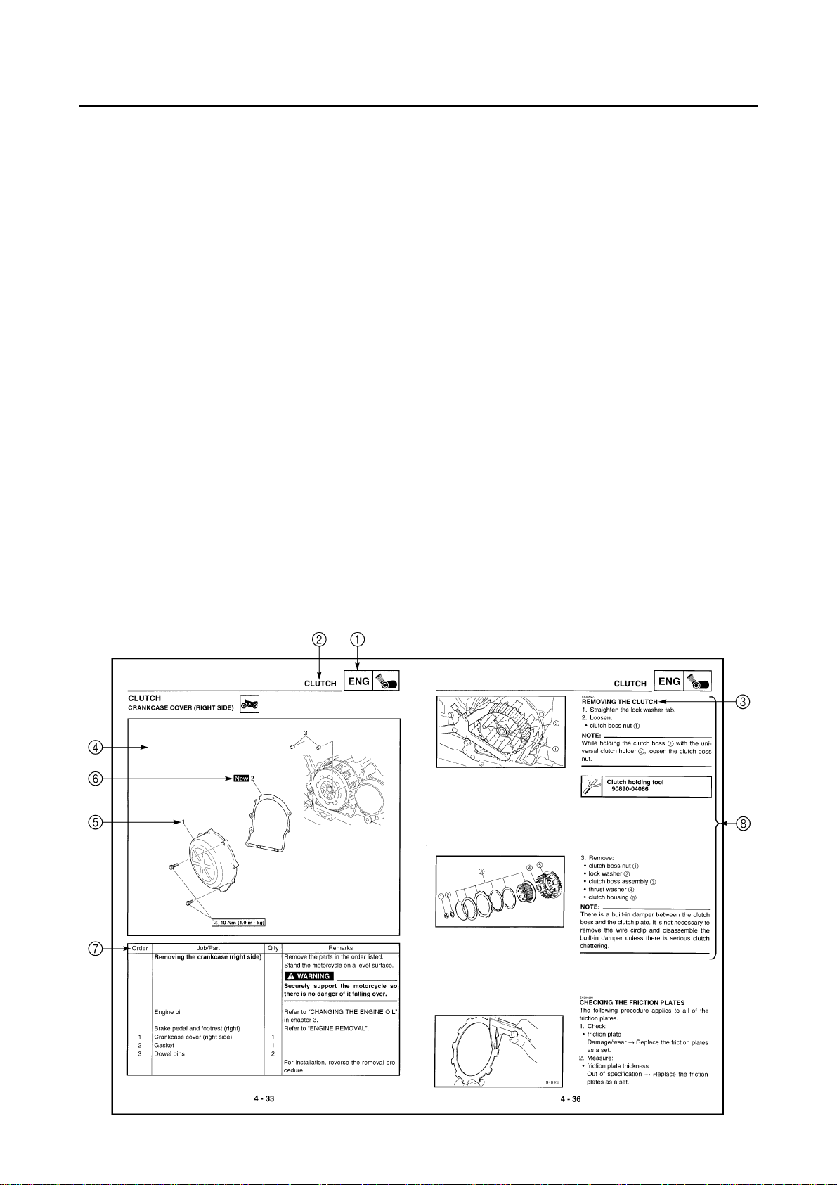
The manual is divided into chapters. An abbreviation and symbol in the upper right corner of
1
each page indicate the current chapter.
Refer to “SYMBOLS”.
Each chapter is divided into sections. The current section title is shown at the top of each page,
2
except in chapter 3 (“PERIODIC CHECKS AND ADJUSTMENTS”), where the sub-section title(s)
appears.
Sub-section titles appear in smaller print than the section title.
3
To help identify parts and clarify procedure steps, there are exploded diagrams at the start of
4
each removal and disassembly section.
Numbers are given in the order of the jobs in the exploded diagram. A circled number indicates a
5
disassembly step.
Symbols indicate parts to be lubricated or replaced.
6
Refer to “SYMBOLS”.
A job instruction chart accompanies the exploded diagram, providing the order of jobs, names of
7
parts, notes in jobs, etc.
Jobs requiring more information (such as special tools and technical data) are described sequen-
8
tially.
12
GEN
SPEC
INFO
34
CHK
ENG
ADJ
56
COOL CARB
78
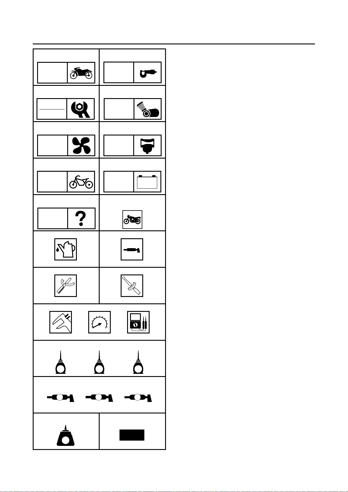
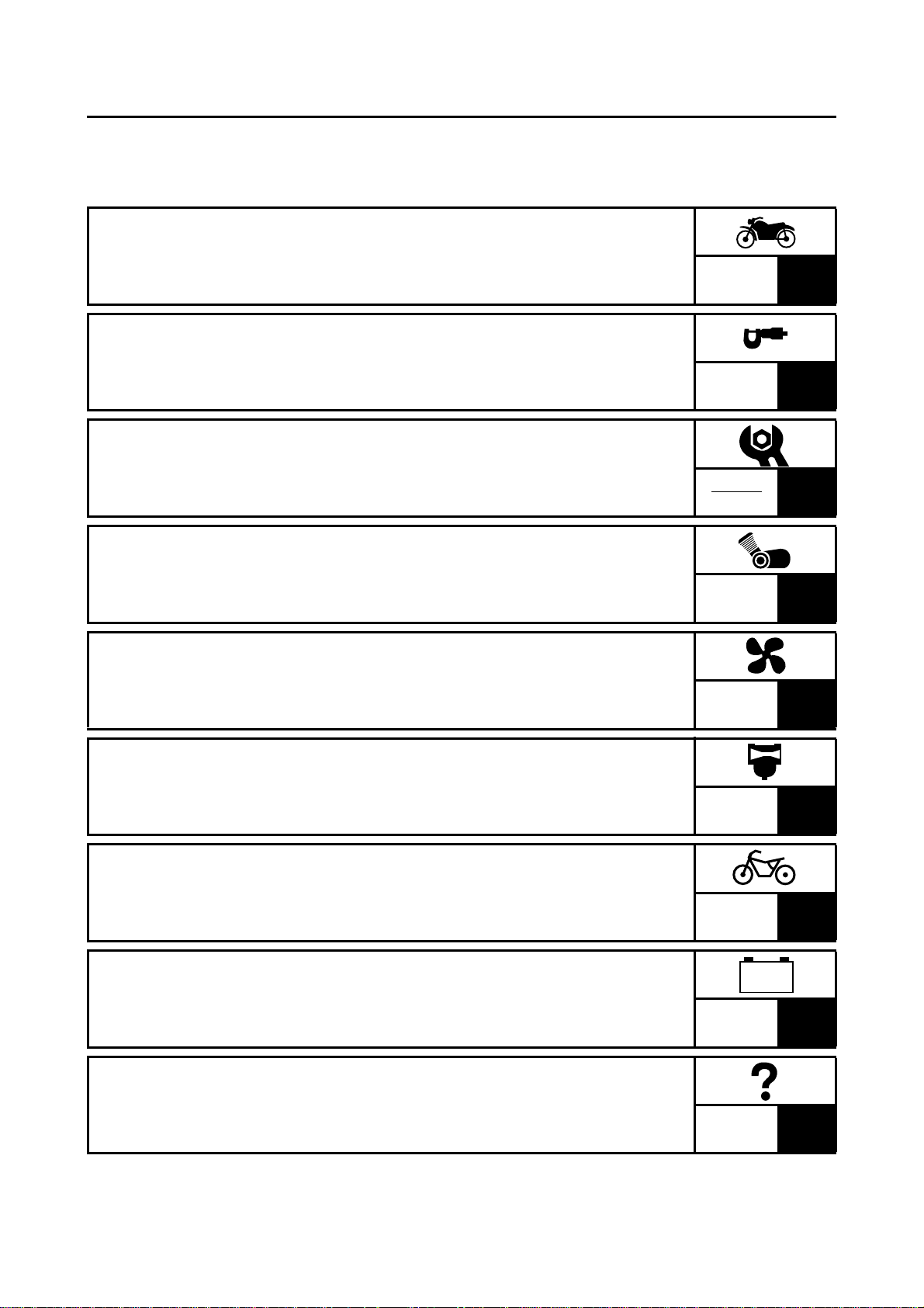
EAS00008
SYMBOLS
The following symbols are not relevant to
every vehicle.
Symbols 1 to 9 indicate the subject of each
chapter.
General information
1
Specifications
2
Periodic checks and adjustments
3
Engine
4
Cooling system
5
Carburetion
6
Chassis
7
Electrical system
8
Troubleshooting
9
CHAS
90
ELEC
–+
TRBL
SHTG
AB
CD
T
.
R
.
EFG
HIJ
Symbols 0 to G indicate the following.
Serviceable with engine mounted
0
Filling fluid
A
Lubricant
B
Special tool
C
Tightening torque
D
Wear limit, clearance
E
Engine speed
F
Electrical data
G
Symbols H to M in the exploded diagrams
indicate the types of lubricants and lubrication
points.
LS
G
M
M
New
E
KLM
B
NO
LT
Engine oil
H
Gear oil
I
Molybdenum disulfide oil
J
Wheel bearing grease
K
Lithium soap base grease
L
Molybdenum disulfide grease
M
Symbols N to O in the exploded diagrams
indicate the following.
Apply locking agent (LOCTITE
N
Replace the part
O
®
)
EAS00012
–+
TABLE OF CONTENTS
GENERAL INFORMATION
SPECIFICATIONS
PERIODIC CHECKS AND
ADJUSTMENTS
ENGINE
COOLING SYSTEM
GEN
INFO
SPEC
CHK
ADJ
ENG
COOL
1
2
3
4
5
CARBURETION
CHASSIS
ELECTRICAL SYSTEM
TROUBLESHOOTING
CARB
CHAS
ELEC
TRBL
SHTG
6
7
8
9

GEN
INFO
1

GEN
INFO
CHAPTER 1
GENERAL INFORMATION
MOTORCYCLE IDENTIFICATION .................................................................1-1
VEHICLE IDENTIFICATION NUMBER ....................................................1-1
MODEL CODE .........................................................................................1-1
IMPORTANT INFORMATION ........................................................................1-2
PREPARATION FOR REMOVAL AND DISASSEMBLY ..........................1-2
REPLACEMENT PARTS ..........................................................................1-2
GASKETS, OIL SEALS AND O-RINGS ...................................................1-2
LOCK WASHERS/PLATES AND COTTER PINS ....................................1-3
BEARINGS AND OIL SEALS ...................................................................1-3
CIRCLIPS .................................................................................................1-3
CHECKING THE CONNECTIONS ...........................................................1-4
SPECIAL TOOLS ...........................................................................................1-5

GEN
INFO
MOTORCYCLE IDENTIFICATION
EAS00014
GENERAL INFORMATION
MOTORCYCLE IDENTIFICATION
EAS00017
VEHICLE IDENTIFICATION NUMBER
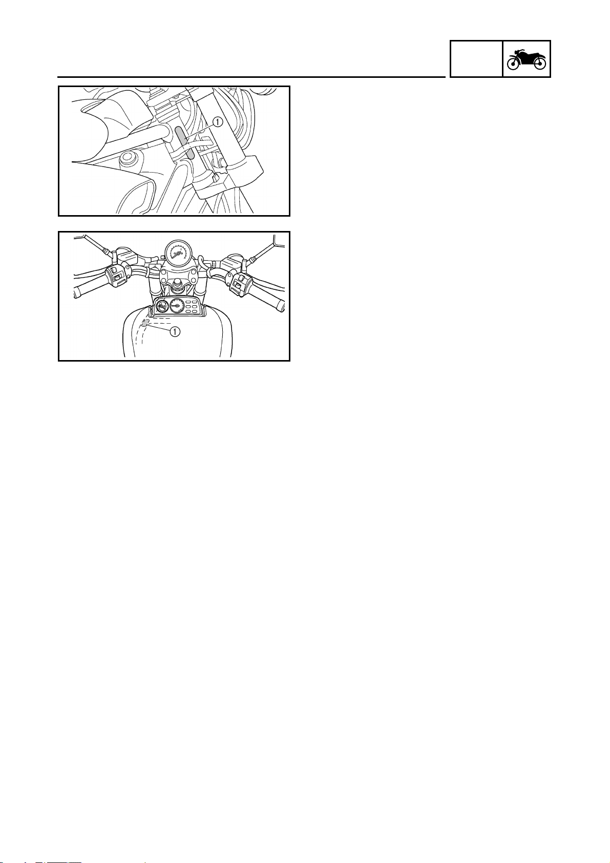
The vehicle identification number 1 is
stamped into the right side of the steering head
pipe.
EAS00018
MODEL CODE
The model code label 1 is affixed to the
frame. This information will be needed to order
spare parts.
GEN
INFO
1 - 1
IMPORTANT INFORMATION
EAS00020
IMPORTANT INFORMATION
PREPARATION FOR REMOVAL AND
DISASSEMBLY
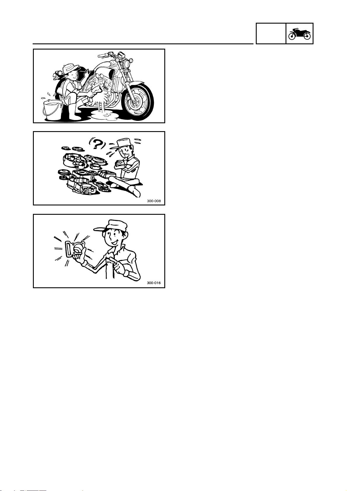
1. Before removal and disassembly, remove all
dirt, mud, dust and foreign material.
2. Use only the proper tools and cleaning
equipment. Refer to the “SPECIAL T OOLS”.
3. When disassembling, always keep mated
parts together. This includes gears, cylinders, pistons and other parts that have been
“mated” through normal wear. Mated parts
must always be reused or replaced as an
assembly.
4. During disassembly, clean all of the parts
and place them in trays in the order of disassembly. This will speed up assembly and
allow for the correct installation of all parts.
5. Keep all parts away from any source of fire.
GEN
INFO
EAS00021
REPLACEMENT PARTS
Use only genuine Yamaha parts for all
replacements. Use oil and grease recommended by Yamaha for all lubrication jobs.
Other brands may be similar in function and
appearance, but inferior in quality.
EAS00022
GASKETS, OIL SEALS AND O-RINGS
1. When overhauling the engine, replace all
gaskets, seals and O-rings. All gasket surfaces, oil seal lips and O-rings must be
cleaned.
2. During reassembly, properly oil all mating
parts and bearings and lubricate the oil seal
lips with grease.
1 - 2
IMPORTANT INFORMATION
EAS00023
LOCK WASHERS/PLATES AND COTTER
PINS
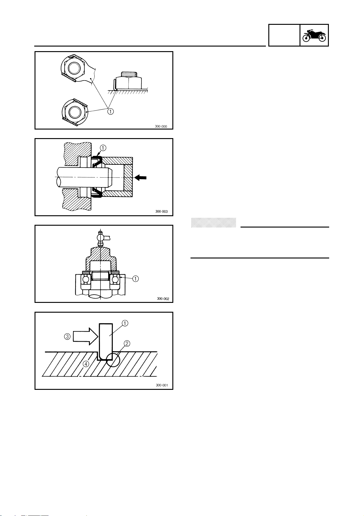
After removal, replace all lock washers/plates
and cotter pins. After the bolt or nut has
1
been tightened to specification, bend the lock
tabs along a flat of the bolt or nut.
EAS00024
BEARINGS AND OIL SEALS
Install bearings and oil seals so that the manufacturer’s marks or numbers are visible. When
installing oil seals, lubricate the oil seal lips
with a light coat of lithium soap base grease.
Oil bearings liberally when installing, if appropriate.
GEN
INFO
Oil seal
1
CAUTION:
@
Do not spin the bearing with compressed
air because this will damage the bearing
surfaces.
@
Bearing
1
EAS00025
CIRCLIPS
Before reassembly, check all circlips carefully
and replace damaged or distorted circlips.
Always replace piston pin clips after one use.
When installing a circlip 1, make sure the
sharp-edged corner 2 is positioned opposite
the thrust 3 that the circlip receives.
Shaft
4
1 - 3
IMPORTANT INFORMATION
EAS00026
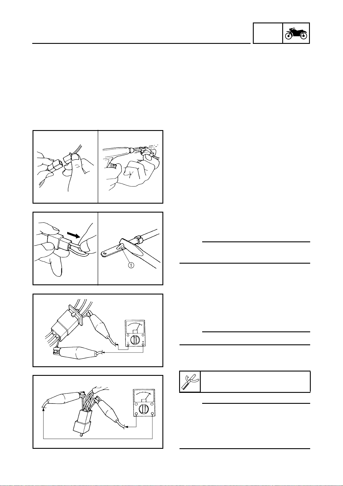
CHECKING THE CONNECTIONS
Check the leads, couplers, and connectors for
stains, rust, moisture, etc.
1. Disconnect:
• lead
• coupler
• connector
2. Check:
• lead
• coupler
• connector
Moisture → Dry with an air blower.
Rust/stains → Connect and disconnect several times.
GEN
INFO
3. Check:
• all connections
Loose connection → Connect properly.
NOTE:
@
If the pin 1 on the terminal is flattened, bend it
up.
@
4. Connect:
• lead
• coupler
• connector
NOTE:
@
Make sure all connections are tight.
@
5. Check:
• continuity (with the pocket tester)
Pocket tester
90890-03112
NOTE:
@
• If there is no continuity, clean the terminals.
• When checking the wire harness, perform
steps (1) to (3).
• As a quick remedy, use a contact revitalizer
available at most part stores.
@
1 - 4
GEN
SPECIAL TOOLS
EAS00027
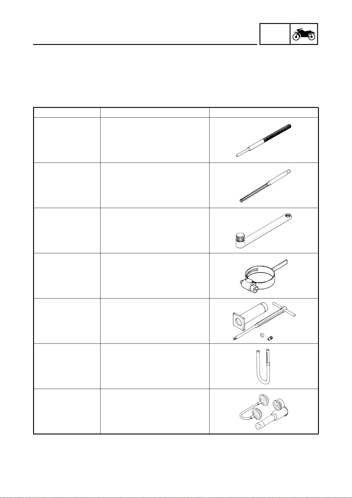
SPECIAL TOOLS
The following special tools are necessary for complete and accurate tune-up and assembly. Use
only the appropriate special tools as this will help prevent damage caused by the use of inappropriate tools or improvised techniques. Special tools, part numbers or both may differ depending on the
country.
When placing an order, refer to the list provided below to avoid any mistakes.
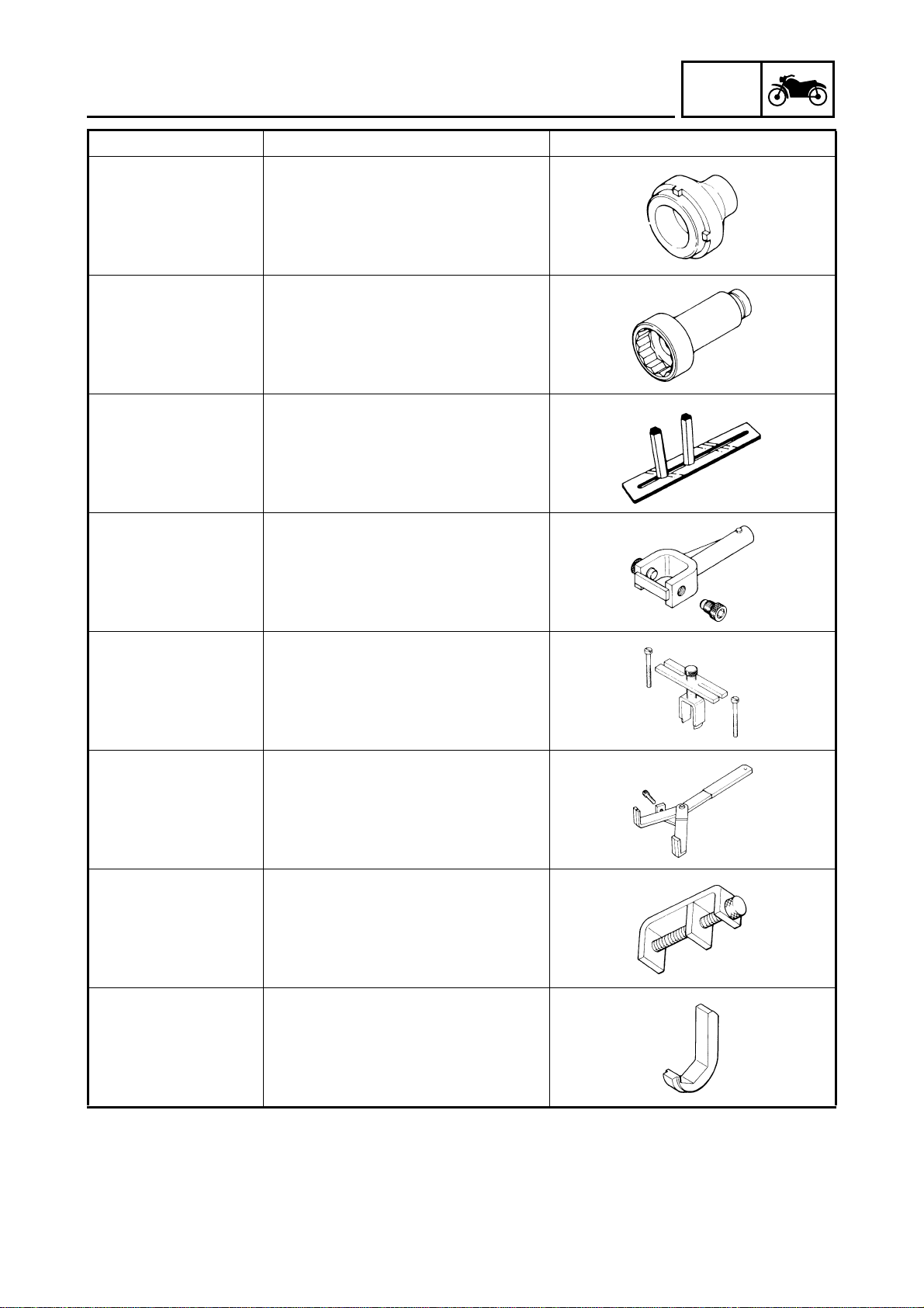
Tool No. Tool name/Function Illustration
Valve guide remover (5.5 mm)
90890-01122
This tool is needed to remove and
install the valve guide.
Valve guide reamer (5.5 mm)
90890-01196
This tool is needed to rebore the new
valve guide.
Coupling gear/middle shaft tool
INFO
90890-01229
90890-01230
90890-01304
90890-01312
Tester
90890-01325
Adapter
90890-01352
This tool is needed when removing or
installing the coupling gear nut.
Final gear backlash band
This tool is needed when measuring
final gear backlash.
Piston pin puller set
This tool is used to remove the piston
pin.
Fuel level gauge
This gauge is used to measure the fuel
level in the float chamber.
Radiator cap tester
Adapter
This tester and its adapter are needed
for checking the cooling system.
1 - 5
GEN
SPECIAL TOOLS
Tool No. Tool name/Function Illustration
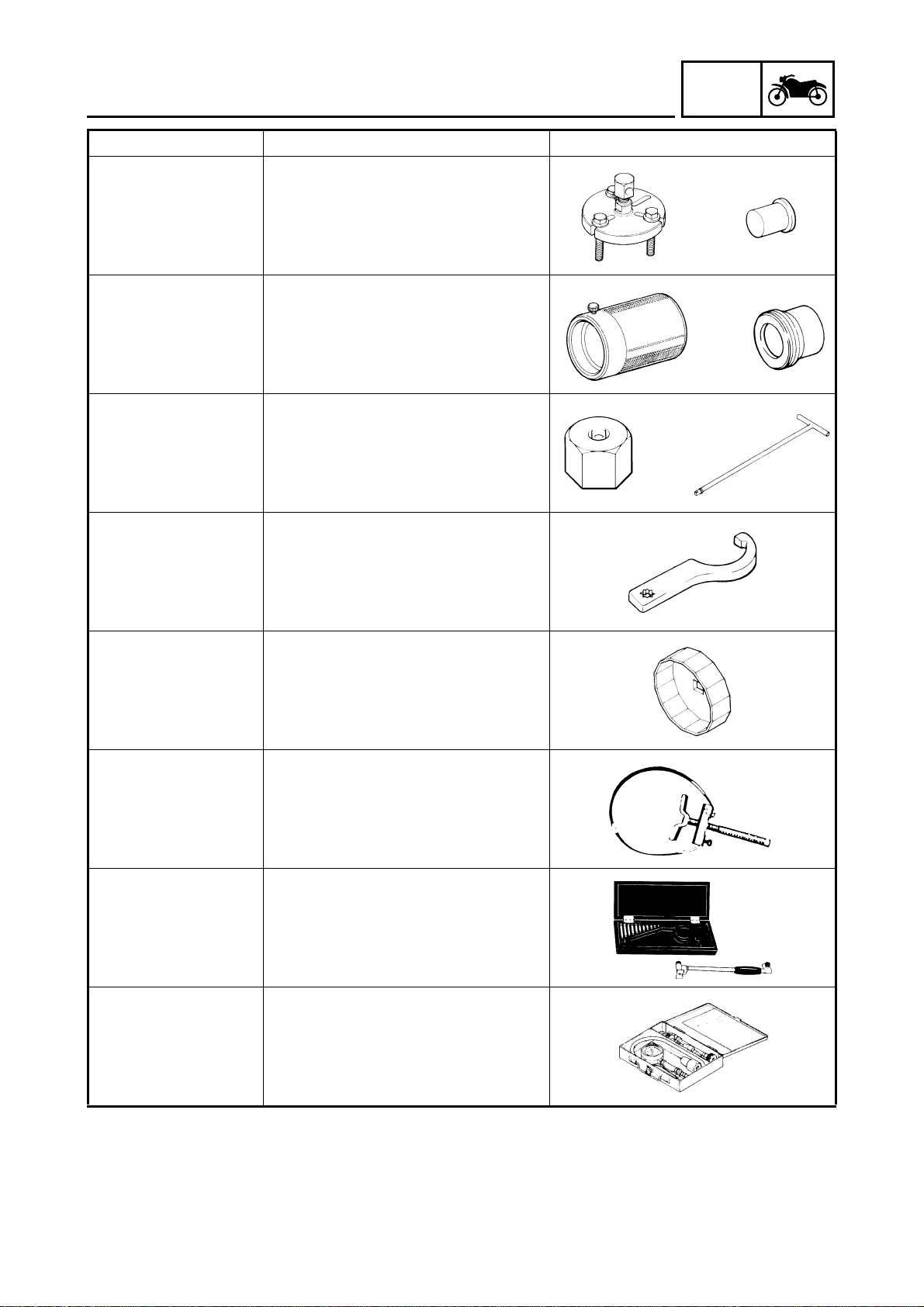
Flywheel puller
Puller
90890-01362
Attachment
90890-04089
Weight
90890-01367
Attachment
90890-01373
Rod holder
90890-01375
T-handle
90890-01326
Attachment
These tools are needed to remove the
rotor.
Fork seal driver weight
Attachment (f40)
These tools are needed when installing
the slide metal, oil seal and dust seal
into the fork.
Damper rod holder (29 mm)
T-handle
These tools are needed to loosen and
tighten the damper rod holding bolt.
Steering nut wrench
INFO
90890-01403
90890-01426
90890-01701
90890-03017
This tool is needed to loosen and
tighten the steering stem ring nut.
Oil filter wrench
This tool is needed to remove and
install the oil filter.
Sheave holder
This tool is needed to hold the rotor
when removing or installing the rotor
bolt.
Cylinder bore gauge (50 ~ 100 mm)
This tool is used to measure the cylinder bore.
Compression gauge
90890-03081
These tools are needed to measure
engine compression.
1 - 6
GEN
SPECIAL TOOLS
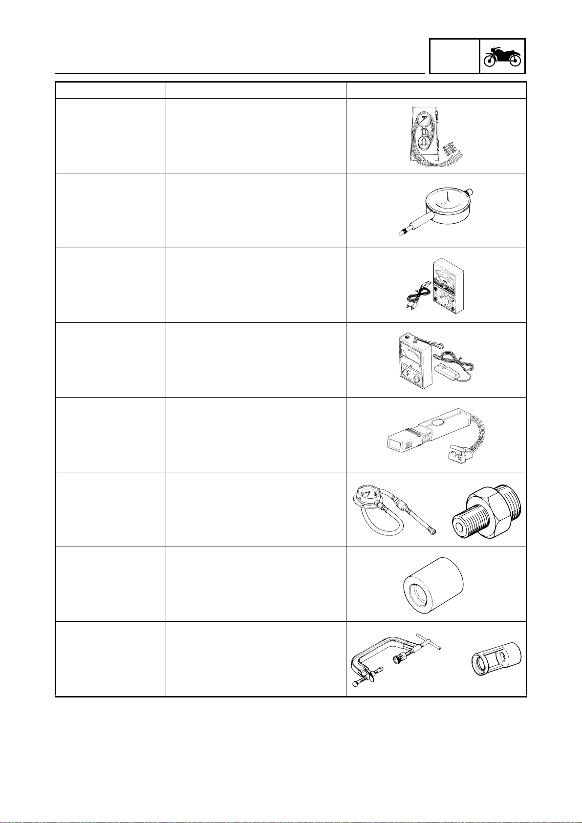
Tool No. Tool name/Function Illustration
Vacuum gauge
90890-03094
This gauge is needed for carburetor
synchronization.
Dial gauge
90890-03097
This tool is used to measure the middle
gear backlash.
Pocket tester
90890-03112
This instrument is needed for checking
the electrical system.
Engine tachometer
INFO
90890-03113
90890-03141
Gauge
90890-03153
Oil pressure adaptor B
90890-03124
90890-04015
Compressor
90890-04019
Attachment
90890-04114
This tool is needed for observing engine
rpm.
Timing light
This tool is necessary for checking ignition timing.
Pressure gauge
Oil pressure adaptor B
These tools are needed to measure
engine oil pressure.
Valve guide installer (5.5 mm)
This tool is needed to install the valve
guide.
Valve spring compressor/attachment
These tools are needed to remove and
install the valve assemblies.
1 - 7
GEN
SPECIAL TOOLS
Tool No. Tool name/Function Illustration
Bearing retainer wrench
90890-04050
This tool is needed when removing or
installing the final drive shaft bearing.
Middle drive shaft nut wrench (55 mm)
90890-04054
This tool is needed when removing or
installing the middle drive shaft nut.
Middle drive gear holder
INFO
YM-33222
90890-04062
90890-04080
90890-04086
This tool is needed to remove and
install the middle drive pinion gear.
This tool is also used for the gear backlash adjustment.
Universal joint holder
This tool is needed when removing or
installing the driven pinion gear nut.
Middle gear backlash tool
This tool is needed for the gear backlash adjustment.
Clutch holding tool
This tool is needed to hold the clutch
when removing or installing the clutch
boss nut.
Damper spring compressor
90890-04090
90890-04105
This tool is needed when removing or
installing the damper spring.
Tappet adjusting tool
This tool is needed to rotate the camshaft for access to the valve lifter and
valve pad.
1 - 8
GEN
SPECIAL TOOLS
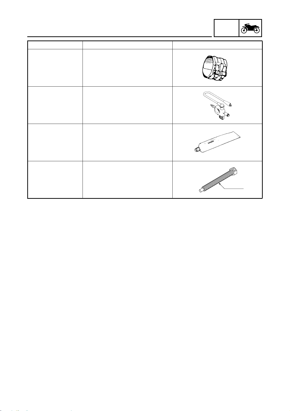
Tool No. Tool name/Function Illustration
Piston ring compressor
INFO
90890-05158
90890-06754
90890-85505
90890-01524
This tool is used to compress the piston
rings when installing the piston into the
cylinder.
Ignition checker
Yamaha Bond No. 1215
This sealant (bond) is used on crankcase mating surfaces, etc.
Ring gear fix bolt (M14)
This tool is used to measure the gear
lash.
M14×P1.5
1 - 9

SPEC
2

SPEC
CHAPTER 2
SPECIFICATIONS
GENERAL SPECIFICATIONS .......................................................................2-1
ENGINE SPECIFICATIONS ..........................................................................2-2
CHASSIS SPECIFICATIONS .......................................................................2-11
ELECTRICAL SPECIFICATIONS ................................................................2-14
CONVERSION TABLE .................................................................................2-17
GENERAL TIGHTENING TORQUE SPECIFICATION.................................2-17
TIGHTENING TORQUES .............................................................................2-18
ENGINE TIGHTENING TORQUES ........................................................2-18
CHASSIS TIGHTENING TORQUES ......................................................2-21
LUBRICATION POINTS AND LUBRICANT TYPES ...................................2-23
ENGINE ..................................................................................................2-23
CHASSIS ...............................................................................................2-24
COOLING SYSTEM DIAGRAMS .................................................................2-25
OIL FLOW DIAGRAMS ................................................................................2-27
CABLE ROUTING ........................................................................................2-31

SPEC
GENERAL SPECIFICATIONS
SPEC
SPECIFICATIONS
GENERAL SPECIFICATIONS
Item Standard Limit
Dimensions
Overall length 2,300 mm ---Overall width 795 mm ---Overall height 1,160 mm ---Seat height 765 mm ---Wheelbase 1,590 mm ---Minimum ground clearance 145 mm ---Minimum turning radius 2,900 mm ----
Weight
Wet (with oil and a full fuel tank) 281 kg ---Dry (without oil and fuel) 262 kg ---Maximum load (total of cargo, rider,
passenger, and accessories)
209 kg ----
2 - 1
ENGINE SPECIFICATIONS
SPEC
ENGINE SPECIFICATIONS
Item Standard Limit
Engine
Engine type Liquid-cooled, 4-stroke, DOHC ---Displacement 1,198 cm
Cylinder arrangement V-type 4-cylinder ---Bore × stroke 76 × 66 mm ---Compression ratio 10.5 : 1 ---Engine idling speed 950 ~ 1,050 r/min ---Vacuum pressure at engine idling
speed
Standard compression pressure
(at sea level)
Fuel
Recommended fuel Regular unleaded gasoline ---Fuel tank capacity
Total (including reserve) 15 L ---Reserve only 3 L ----
Engine oil
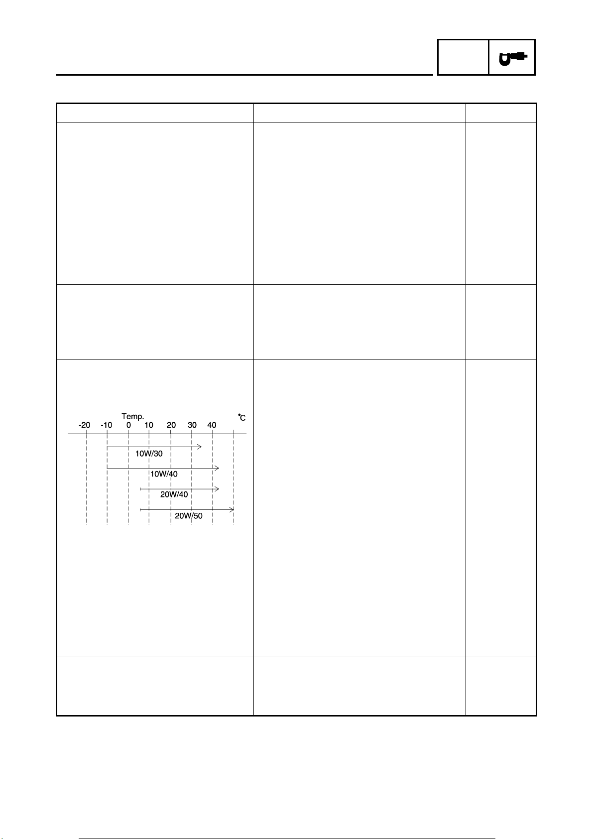
Lubrication system Wet sump ---Recommended oil
26.7 kPa (200 mm Hg) ----
1,450 kPa (14.5 kgf/cm
3
----
2
) at 350 r/min ----
----
SAE 20W40SE or SAE 10W30SE
Quantity
Total amount 4 L ---Without oil filter cartridge replace-
ment
With oil filter cartridge replacement 3.4 L ----
Oil pressure (hot) 25 kPa at 1,000 r/min
Relief valve opening pressure 440 ~ 560 kPa (4.4 ~ 5.6 kgf/cm
Final gear oil
Recommended oil SAE 80 API “GL-4” Hypoid Gear Oil ---Final gear case oil
Total amount 0.2 L ----
3.2 L ----
2
(0.25 kgf/cm
at 1,000 r/min)
2
) ----
----
----
2 - 2
ENGINE SPECIFICATIONS
Item Standard Limit
Oil filter
Oil filter type Cartridge (paper) ---Bypass valve opening pressure 170 ~ 240 kPa (1.7 ~ 2.4 kgf/cm
Oil pump
Oil pump type Trochoid ---Inner-rotor-to-outer-rotor-tip clearance 0 ~ 0.12 mm 0.17 mm
Outer-rotor-to-oil-pump-housing
clearance
Cooling system
Radiator capacity 3.05 L ---Radiator cap opening pressure 75 ~ 105 kPa (0.75 ~ 1.05 kgf/cm
Radiator core
Width 363.8 mm ---Height 240 mm ---Depth 16 mm ----
Coolant reservoir
Capacity 0.3 L ---<From low to full level> 0.2 L ----
Water pump
Water pump type Single-suction centrifugal pump ---Reduction ratio 31/21 (1.476) ---Max. impeller shaft tilt ---- 0.15 mm
Starting system type Electric starter ----
Spark plugs
Model (manufacturer) × quantity DPR8EA-9/X24EPR-U9 (NGK/DENSO) × 4 ----
Spark plug gap 0.8 ~ 0.9 mm ----
Cylinder head
Max. warpage ---- 0.03 mm
0.03 ~ 0.08 mm 0.08 mm
SPEC
2
) ----
2
) ----
2 - 3
ENGINE SPECIFICATIONS
Item Standard Limit
Camshafts
Drive system Chain drive (center) ---Camshaft cap inside diameter 25.000 ~ 25.021 mm ---Camshaft journal diameter 24.967 ~ 24.980 mm ---Camshaft-journal-to-camshaft-cap
clearance
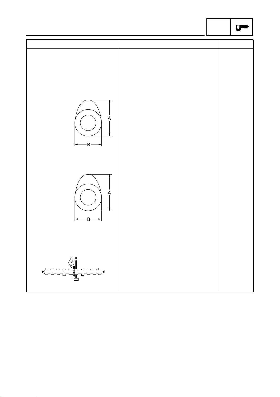
Intake camshaft lobe dimensions
Measurement A 36.25 ~ 36.35 mm 36.15 mm
Measurement B 28.02 ~ 28.12 mm 27.92 mm
Exhaust camshaft lobe dimensions
0.020 ~ 0.054 mm ----
SPEC
Measurement A 36.25 ~ 36.35 mm 36.15 mm
Measurement B 28.02 ~ 28.12 mm 27.92 mm
Max. camshaft runout ---- 0.03 mm
2 - 4
ENGINE SPECIFICATIONS
SPEC
Item Standard Limit
Timing chain
Model/number of links 219FTS/117 ---Tensioning system Automatic ----
Valves, valve seats, valve guides
Valve clearance (cold)
Intake 0.11 ~ 0.15 mm ---Exhaust 0.26 ~ 0.30 mm ----
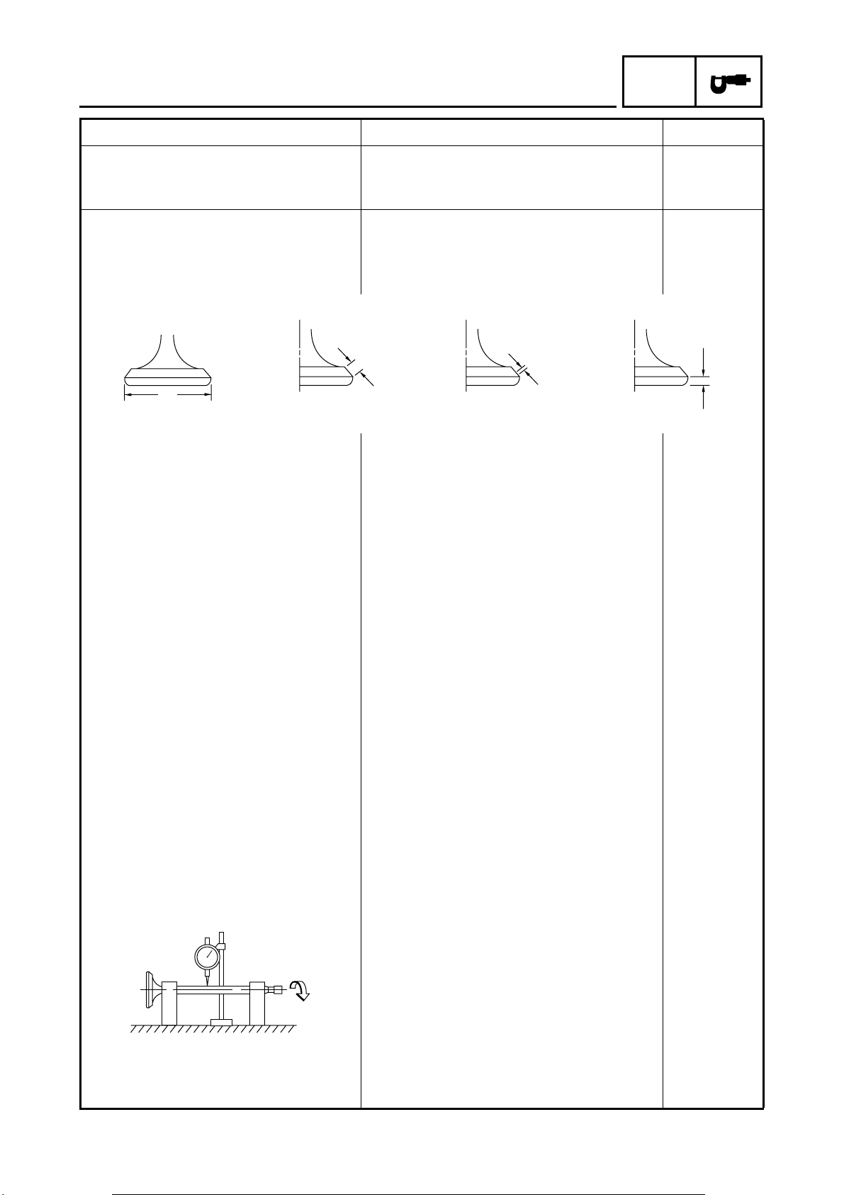
Valve dimensions
A
Head Diameter
Face Width
B
Seat Width
C
D
Margin Thickness
Valve head diameter A
Intake 30.4 ~ 30.6 mm ---Exhaust 24.9 ~ 25.1 mm ----
Valve face width B
Intake 1.6 ~ 3.1 mm ---Exhaust 1.3 ~ 2.4 mm ----
Valve seat width C
Intake 0.9 ~ 1.1 mm 1.4 mm
Exhaust 0.9 ~ 1.1 mm 1.4 mm
Valve margin thickness D
Intake 1.1 ~ 1.5 mm 0.7 mm
Exhaust 1.1 ~ 1.5 mm 0.7 mm
Valve stem diameter
Intake 5.475 ~ 5.490 mm 5.445 mm
Exhaust 5.460 ~ 5.475 mm 5.42 mm
Valve guide inside diameter
Intake 5.500 ~ 5.512 mm 5.55 mm
Exhaust 5.500 ~ 5.512 mm 5.55 mm
Valve-stem-to-valve-guide clearance
Intake 0.010 ~ 0.037 mm 0.08 mm
Exhaust 0.025 ~ 0.052 mm 0.1 mm
Valve stem runout ---- 0.01 mm
Valve seat width
Intake 0.9 ~ 1.1 mm 1.4 mm
Exhaust 0.9 ~ 1.1 mm 1.4 mm
2 - 5
ENGINE SPECIFICATIONS
Item Standard Limit
Valve springs
Inner springs
Free length
Intake 39.65 mm 37.45 mm
Exhaust 39.65 mm 37.45 mm
Installed length (valve closed)
Intake 31.8 mm ---Exhaust 31.8 mm ----
Compressed spring force (installed)
Intake 61.7 ~ 72.5 N (6.29 ~ 7.39 kgf) ---Exhaust 61.7 ~ 72.5 N (6.29 ~ 7.39 kgf) ----
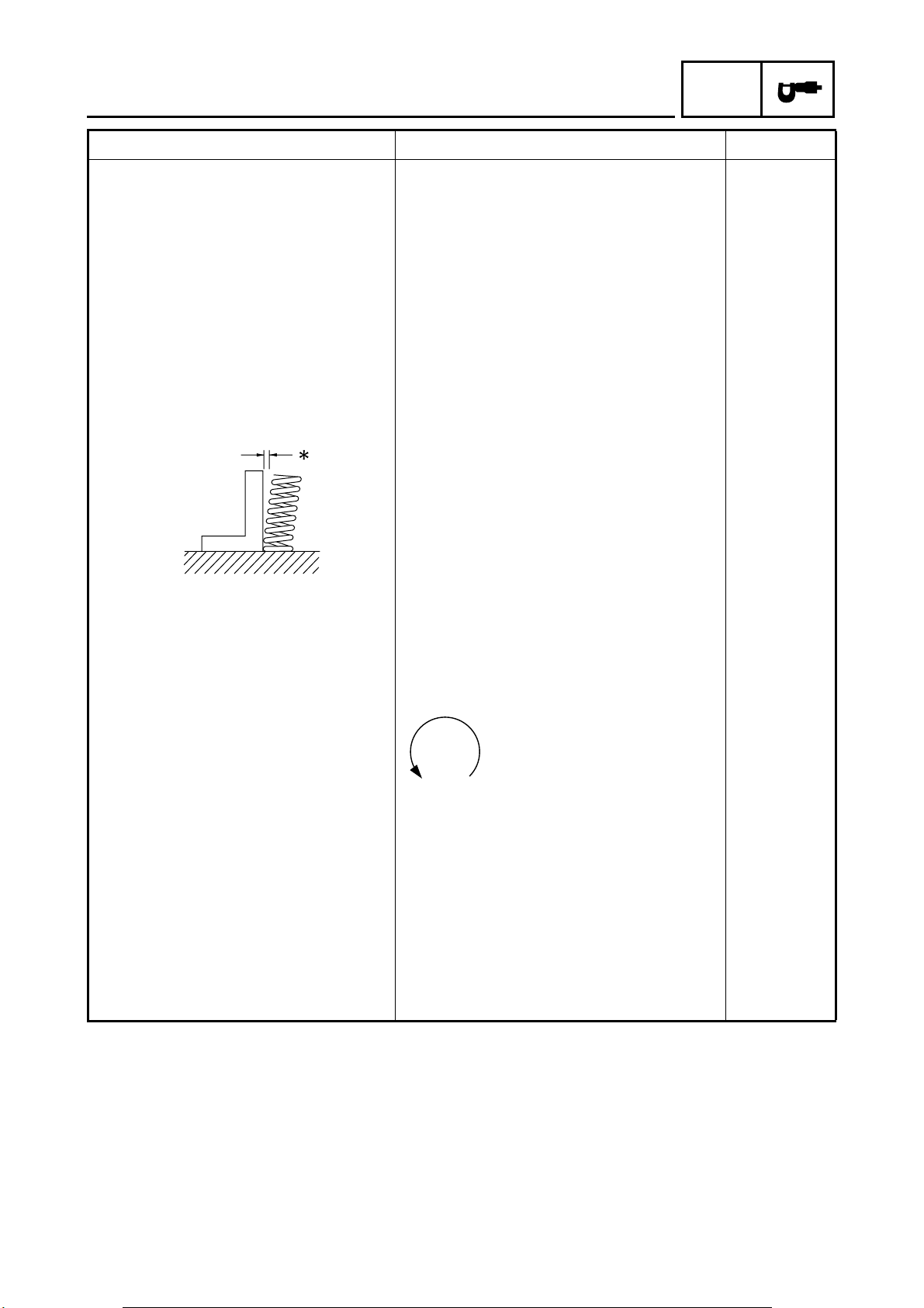
Spring tilt
SPEC
Intake ---- 2.5° /1.7 mm
Exhaust ---- 2.5° /1.7 mm
Winding direction (top view)
Intake Counterclockwise ---Exhaust Counterclockwise ----
Outer springs
Free length
Intake 41.1 mm 38.9 mm
Exhaust 41.1 mm 38.9 mm
Installed length (valve closed)
Intake 33.8 mm ---Exhaust 33.8 mm ----
Compressed spring force (installed)
Intake 130.4 ~ 154.0 N (13.3 ~ 15.7 kgf) ---Exhaust 130.4 ~ 154.0 N (13.3 ~ 15.7 kgf) ----
2 - 6
 Loading...