

Page 1

USB AUDIO/MIDI PERSONAL STUDIO
USB AUDIO/MIDI PERSONAL STUDIO
EnglishDeutschFrançais
Owner‘s Manual
Bedienungsanleitung
Mode d’emploi
Page 2

SPECIAL MESSAGE SECTION
This product utilizes batteries or an external power supply
(adapter). DO NOT connect this product to any power
supply or adapter other than one described in the manual,
on the name plate, or specifically recommended by
Yamaha.
WARNING: Do not place this product in a position
where anyone could walk on, trip over ,or roll anything
over power or connecting cords of any kind. The use of an
extension cord is not recommended! IF you must use an
extension cord, the minimum wire size for a 25' cord (or
less ) is 18 AWG. NOTE: The smaller the AWG number
,the larger the current handling capacity. For longer
extension cords, consult a local electrician.
This product should be used only with the components
supplied or; a cart, rack, or stand that is recommended by
Yamaha. If a cart, etc., is used, please observe all safety
markings and instructions that accompany the accessory
product.
SPECIFICATIONS SUBJECT TO
CHANGE:
The information contained in this manual is believed to be
correct at the time of printing. However, Yamaha reserves
the right to change or modify any of the specifications
without notice or obligation to update existing units.
This product, either alone or in combination with an
amplifier and headphones or speaker/s, may be capable
of producing sound levels that could cause permanent
hearing loss. DO NOT operate for long periods of time at
a high volume level or at a level that is uncomfortable. If
you experience any hearing loss or ringing in the ears,
you should consult an audiologist.
IMPORTANT: The louder the sound, the shorter the time
period before damage occurs.
Some Yamaha products may have benches and / or
accessory mounting fixtures that are either supplied with
the product or as optional accessories. Some of these
items are designed to be dealer assembled or installed.
Please make sure that benches are stable and any
optional fixtures (where applicable) are well secured
BEFORE using.
Benches supplied by Yamaha are designed for seating
only. No other uses are recommended.
NOTICE:
Service charges incurred due to a lack of knowledge
relating to how a function or effect works (when the unit is
operating as designed) are not covered by the
manufacturer’s warranty, and are therefore the owners
responsibility. Please study this manual carefully and
consult your dealer before requesting service.
ENVIRONMENTAL ISSUES:
Yamaha strives to produce products that are both user
safe and environmentally friendly. We sincerely believe
that our products and the production methods used to
produce them, meet these goals. In keeping with both the
letter and the spirit of the law, we want you to be aware of
the following:
Battery Notice:
This product MAY contain a small non-rechargeable
battery which (if applicable) is soldered in place. The
average life span of this type of battery is approximately
five years. When replacement becomes necessary, contact
a qualified service representative to perform the replacement.
This product may also use “household” type batteries.
Some of these may be rechargeable. Make sure that the
battery being charged is a rechargeable type and that the
charger is intended for the battery being charged.
When installing batteries, do not mix batteries with new, or
with batteries of a different type. Batteries MUST be
installed correctly. Mismatches or incorrect installation may
result in overheating and battery case rupture.
Warning:
Do not attempt to disassemble, or incinerate any battery.
Keep all batteries away from children. Dispose of used
batteries promptly and as regulated by the laws in your
area. Note: Check with any retailer of household type
batteries in your area for battery disposal information.
Disposal Notice:
Should this product become damaged beyond repair, or for
some reason its useful life is considered to be at an end,
please observe all local, state, and federal regulations that
relate to the disposal of products that contain lead,
batteries, plastics, etc. If your dealer is unable to assist
you, please contact Yamaha directly.
NAME PLATE LOCATION:
The name plate is located on the top panel of the product.
The name plate lists the product’s model number, power
requirements, and other information. The serial number is
located on the rear panel. Please record the model
number, serial number, and date of purchase in the spaces
provided below, and keep this manual as a permanent
record of your purchase.
Model
Serial No.
Purchase Date
92-BP (others)
PLEASE KEEP THIS MANUAL
Page 3
PRECAUTIONS
PLEASE READ CAREFULLY BEFORE PROCEEDING
* Please keep these precautions in a safe place for future reference.
WARNING
Always follow the basic precautions listed below to avoid the possibility of serious injury or even death from
electrical shock, short-circuiting, damages, fire or other hazards. These precautions include, but are not limited
to, the following:
• Do not open the instrument or attempt to disassemble
the internal parts or modify them in any way. The
instrument contains no user-serviceable parts. If it should
appear to be malfunctioning, discontinue use
immediately and have it inspected by qualified Yamaha
service personnel.
• Do not expose the instrument to rain, use it near water
or in damp or wet conditions, or place containers on it
containing liquids which might spill into any openings.
• If the AC adaptor cord or plug becomes frayed or
damaged, or if there is a sudden loss of sound during
use of the instrument, or if any unusual smells or smoke
should appear to be caused by it, immediately turn off
CAUTION
Always follow the basic precautions listed below to avoid the possibility of physical injury to you or others, or
damage to the instrument or other property. These precautions include, but are not limited to, the following:
• Do not place the AC adaptor cord near heat sources
such as heaters or radiators, and do not excessively
bend or otherwise damage the cord, place heavy objects
on it, or place it in a position where anyone could walk
on, trip over, or roll anything over it.
• When removing the electric plug from the instrument or
an outlet, always hold the plug itself and not the cord.
• Do not connect the instrument to an electrical outlet using
a multiple-connector. Doing so can result in lower sound
quality, or possibly cause overheating in the outlet.
• Unplug the AC power adaptor when not using the
instrument, or during electrical storms.
• Before connecting the instrument to other electronic
components, turn off the power for all components.
Before turning the power on or off for all components,
set all volume levels to minimum. Also, be sure to set
the volumes of all components at their minimum levels
and gradually raise the volume controls while playing
the instrument to set the desired listening level.
• Do not expose the instrument to excessive dust or
vibrations, or extreme cold or heat (such as in direct
sunlight, near a heater, or in a car during the day) to
prevent the possibility of panel disfiguration or damage
to the internal components.
• Do not use the instrument near other electrical products
such as televisions, radios, or speakers, since this might
cause interference which can affect proper operation of
the other products.
• Do not place the instrument in an unstable position where
it might accidentally fall over.
(3)-6
the power switch, disconnect the adaptor plug from the
outlet, and have the instrument inspected by qualified
Yamaha service personnel.
• Use the specified adaptor (PA-3B or an equivalent
recommended by Yamaha) only. Using the wrong
adaptor can result in damage to the instrument or
overheating.
• Before cleaning the instrument, always remove the
electric plug from the outlet. Never insert or remove an
electric plug with wet hands.
• Check the electric plug periodically and remove any dirt
or dust which may have accumulated on it.
• Before moving the instrument, remove all connected
adaptor and other cables.
• When cleaning the instrument, use a soft, dry cloth. Do
not use paint thinners, solvents, cleaning fluids, or
chemical-impregnated wiping cloths. Also, do not place
vinyl, plastic or rubber objects on the instrument, since
this might discolor the panel or keyboard.
• Do not rest your weight on, or place heavy objects on
the instrument, and do not use excessive force on the
buttons, switches or connectors.
• Do not operate the instrument for a long period of time
at a high or uncomfortable volume level, since this can
cause permanent hearing loss. If you experience any
hearing loss or ringing in the ears, consult a physician.
Yamaha cannot be held responsible for damage
caused by improper use or modifications to the
instrument, or data that is lost or destroyed.
Always turn the power off when the instrument is not in use.
Page 4

Welcome to the UW500
Thank you for choosing the Yamaha UW500 USB Audio/MIDI Personal Studio. The
UW500 is a USB interface that enables simultaneous transfer of audio and MIDI data.
Connect the UW500 to a computer that has a USB port and enjoy the powerful
features of digital audio.
Please read this owner’s manual thoroughly to make the best use of the UW500. After
you read this manual, please keep it in a safe place for future reference.
SPECIAL NOTICES
• The software and this owner’s manual are exclusive copyrights of Yamaha Corporation.
• Use of the software and this manual is governed by the license agreement which the
purchaser fully agrees to upon breaking the seal of the software packaging. (Please
read carefully the Software Licensing Agreement at the end of this manual before
installing the application.)
• Copying of the software or reproduction of this manual in whole or in part by any
means is expressly forbidden without the written consent of the manufacturer.
• Yamaha makes no representations or warranties with regard to the use of the software and documentation and cannot be held responsible for the results of the use of
this manual and the software.
• This disk is a CD-ROM. Do not attempt to play the disk on an audio CD player.
Doing so may result in irreparable damage to your audio CD player.
• Copying of the commercially available music sequence data and/or digital audio files
is strictly prohibited except for your personal use.
• The company names and product names in this Owner’s Manual are the trademarks
or registered trademarks of their respective companies.
• The screen displays as illustrated in this Owner’s Manual are for instructional purposes, and may appear somewhat different from the screens which appear on your
computer.
• Future upgrades of application and system software and any changes in specifications and functions will be announced separately.
* “SoftSynthesizer” is a trademark of Yamaha Corporation.
4
Page 5

Table of contents
UW500 Features .................................................................................. 6
Notes on USB ................................................................................................7
Notes on musical copyrights..........................................................................8
Package Contents ............................................................................... 9
About the included software.......................................................................... 9
System Requirements .......................................................................11
Parts and Functions........................................................................... 12
Connection........................................................................................16
Installing the Driver .......................................................................... 22
Playing the Demo Song .................................................................... 32
Hard Disk Recording ......................................................................... 34
Creating a Song Using Sample Phrases............................................ 40
Changing the driver setting (MIDI Patch Screen) ...........................44
Specifications ....................................................................................50
Troubleshooting (FAQ).....................................................................51
5
Page 6

UW500 Features
Transferring audio and MIDI data simultaneously
•
You can use audio data and MIDI data at the same time.
The audio inputs and outputs of the UW500 support both analog signals (microphone input and line input/output) and digital signals (optical input/output). MIDI
data is transferred via the MIDI IN/OUT terminals and TO TG terminal (which is
equivalent to a computer’s serial port). Multiple-port configuration (6 MIDI outputs
and 2 MIDI inputs) reinforces a powerful musical production environment.
Producing a clear sound
•
Usually, if you try to record audio using a computer’s audio input jack, computer
noise is introduced and lowers the audio quality during the analog-to-digital conversion. The UW500, however, converts analog input signals into digital, which enables
you to record clear sound to your hard disk.
The included software supports a musical production environ-
•
ment
Using the included software, XGworks and TWE facilitate hard disk recording. Even
without external tone generators, you can play both audio data and MIDI data
simultaneously using SoftSynthesizer S-YXG50.
Easy Hot Swap Connection
•
With a USB connection, you can connect and disconnect the USB cable while the
power to the computer is on. You can also use the unit as soon as you install the
driver.
USB Fast Data Transfer
•
USB connection enables a quick response from any connected devices during simultaneous audio and MIDI data performance.
USB
USB is an abbreviation for Universal Serial Bus. It is a serial interface for connecting
a computer with peripheral devices, and enables much faster data transfer
(12Mbps) compared to conventional serial port connections. Also, it allows “hot
swapping” (connecting peripheral devices while the power to the computer is
on).
6
Page 7

UW500 Features
Notes on USB
Don’t turn the power to the UW500 on or off, or connect or disconnect a USB cable
under any of the following conditions. Otherwise, the computer may lock up or
UW500 functions may be disabled:
• The computer is checking the device or loading the driver.
• The computer is starting or quitting the OS.
• The computer is in Save Energy (Sleep) mode or canceling the mode.
• The audio/MIDI application is started.
Also, don’t perform any of the following operations. Otherwise, the computer may
lock up or the UW500 functions may be disabled:
• Do not frequently turn on and off the power to the UW500 or connect and
disconnect the cable.
• Do not place the computer in Save Energy (Sleep) mode or cancel the
mode during audio/MIDI data transfer.
• Do not connect or disconnect the USB cable while the UW500 is on.
• Do not turn the power to the UW500 on or off, start the computer, or
install the driver while a large quantity of data is being transferred.
7
Page 8
UW500 Features
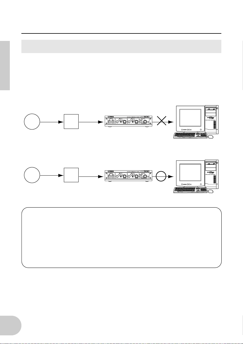
Notes on musical copyrights
The UW500 supports SCMS (Serial Copy Management System) to protect the
copyrights of music software. When you digitally copy data from CDs, or other music
software purchased from stores, to your own media (such as MDs), information
regarding digital recording generation is also recorded. If you route the recorded data
to the DIGITAL IN jack, the data cannot be recorded on the computer. Use analog
inputs (INPUT 1-3 jacks) to record data on the computer.
computer
UW500
digital digital
CD
digital
CD
MD
MD
You cannot
record.
computer
UW500
analog
You can
record.
It is prohibited to use copyrighted songs and sound data (that can be recorded via
the UW500) for commercial purposes. It is also prohibited to reproduce, transfer,
or distribute the data, or play the data for a commercial audience without
permission from the owners of the copyright, except for personal use or
application that does not infringe the copyright. If you wish to use such data for
occasions other than personal use, consult a copyright expert. Yamaha is not
responsible for any data created, reproduced, or edited using the UW500, nor for
any reproduction or use of such data.
8
Page 9

Package Contents
The UW500 package contains the following items. Check the contents for missing
items.
• UW500 main unit
• Power adaptor (PA-3B)
(The power adaptor may not be included in the package in some areas.)
• CD-ROM
• USB cable (approx. 2m)
• Owner’s manual (this book)
About the included software
The included CD-ROM contains the following software.
• USB-MIDI driver (YAMAHA USB-MIDI Driver)
This driver enables the UW500’s MIDI functions.
See page 22 for information on installing the driver.
• XGworks lite V3.0A
This sequence software supports Windows 98 and offers you an opportunity for
high-quality music production. It lets you to create MIDI performance data and process audio data for advanced music post production.
To start the installer, double-click “Setup.exe” in the “XGworks_” folder. Install the
software following the instructions on the display.
For more information on using the software, refer to the “XGworks Manual” PDF file
after you finish the installation. This file is located at [Start|Programs|YAMAHA
XGworks lite Ver.3.0]. Please note that the included Help and PDF files are for
XGworks V3.0. The following functions are not available in XGworks lite V3.0A.
• Staff Window and Printing the Staves
• Drum Window
• Control Section
• Voice To Score R
• Auto Arranger
• Guitar Arranger
• Auto Play
• Importer
• SW1000XG Mixer
• Voice To Score
• XF Information Editor
9
Page 10

Package Contents
• Wave Editor TWE
Wave Editor TWE is used to record and edit Wave files. It is suitable for loading and
editing the Wave files recorded using XGworks.
This software is installed along with XGworks. To start the application, select [Wave
Editor TWE] from the [Job] menu in XGworks. For more information on using the
software, refer to the “Wave Editor TWE Manual” PDF file after you finish the installation. This file is located at [Start|Programs|YAMAHA XGworks lite Ver.3.0].
• SoftSynthesizer (S-YXG50)
The S-YXG50 is XG tone generator software that produces voices using the computer’s CPU power. By installing SoftSynthesizer, you can enjoy high quality tones
from MIDI data performance without connecting an external XG tone generator.
To start the installer, double-click “Setup.exe” in the “Syxg50_” folder. Install SoftSynthesizer according to the instructions on the display.
For more information on using the software, refer to the “S-YXG50 Help” file after
you finish the installation. This file is located at [Start|Programs|YAMAHA SoftSynthesizer S-YXG50].
• Acrobat Reader
The Acrobat Reader allows you to view the electronic Owner’s Manual saved in PDF
format.
To start the installer, open the “English” folder in the “Acroread” folder, then double-click the “Ar40eng.exe.” Install the software according to the instructions on the
display.
10
Page 11

System Requirements
OS: Windows 98 or Windows 98 Second Edition
Computer: USB-supported IBM-PC or compatible computer
CPU: Pentium 166MHz or higher (MMX Pentium 233 MHz or higher is recom-
mended.)
Memory: 32MB or higher (64 MB or higher is recommended.)
Hard Disk: 2MB or more of free space
NOTE
To use XGworks lite V3.0, 30MB or more of hard disk space is
required. To use Wave files, much more space is required.
11
Page 12

Parts and Functions
■
Front Panel
1 2 6 7 83 4 5
A
DIGITAL IN jack
Digital signal is input here from an
MD or CD player using an optical
digital cable (with a square plug). Set
the INPUT SELECT switch on the rear
panel to “DIGITAL.”
DIGITAL OUT jack
B
This jack is used to record a digital
signal from the computer to a digital
recorder, such as an MD recorder.
Use an optical digital cable (with a
square plug) for connection.
NOTE
INPUT 1/2 jacks
C
Audio signal is input here from a
microphone, electric guitar, electric
bass, electronic musical instrument,
or CD player. Use a standard monaural plug cable for connection.
NOTE
Signals input at INPUT 1-3,
AUX IN and DIGITAL IN cannot be route directly to the
DIGITAL OUT jack.
To use INPUT 1-3 jacks, set
the INPUT SELECT switch
on the rear panel to “STEREO” or “MONO.”
D
INPUT 1/2 gain switches
These switches enable you to select a
type of signal input at INPUT 1 and 2
jacks.
For stereo line input, set the gain
switch to “LINE” and input the left
signal to the INPUT 1 jack and the
right signal to the INPUT 2 jack. Set
the INPUT SELECT switch on the rear
panel to “STEREO.”
INPUT 1/2 volume knobs
E
These volume knobs enable you to
adjust the volume level of the audio
signal input at INPUT 1 and 2 jacks.
PHONES jack
F
Connect headphones with a standard jack here. Use the OUTPUT
knob to adjust the headphone volume.
12
Page 13

Parts and Functions
G
OUTPUT knob
This knob has two functions. It
switches the power on and off
(stand-by) each time a click sound is
heard when you turn the knob
When the power is on, the knob
enables you to adjust the UW500’s
overall volume. Note that the OUTPUT knob setting does not affect the
output at the DIGITAL OUT jack and
the input at the AUX IN jacks on the
rear panel.
Even when the power is off
(standby), a small current
flows through the unit. If you
plan not to use the UW500 for
a long period of time, be sure
to remove the power adaptor
from the AC outlet.
H
USB LED
The LED lights up in red when the
power is turned on to the UW500. It
lights up in green when the computer is connected to the UW500
correctly. It flashes in green when the
UW500 transmits or receives MIDI
signal.
The LED lights up in orange if the
INPUT SELECT switch is set to
“TRACK DOWN” (page 15).
The LED flashes in orange if the sampling frequency of the signal input at
the DIGITAL IN jack is not appropriate. In this case, select the correct
frequency option in the application
on the computer according to the
sampling frequency of the input signal.
The LED flashes in red and green
alternately when the copyrighted
signal is input at the DIGITAL IN jack.
The signal cannot be recorded on
the computer (page 8).
13
Page 14

Parts and Functions
■
Rear Panel
90A B C E F GD
L
R
14
I
OUTPUT jacks
These jacks are used to connect a
playback device, such as powered
speakers, or a recording device, such
as a tape recorder. Use RCA pin-plug
cables for L and R connection.
AUX IN jacks
J
These jacks are used to connect an
audio device, such as a CD player.
The input signal is routed to the
OUTPUT jacks and PHONES jack,
bypassing the computer. (The signal
is not routed to the DIGITAL OUT
jack.) Use RCA pin-plug cables for L
and R connection.
NOTE
INPUT 3 jacks
K
You cannot record an audio
signal input from these jacks
to the computer. To record
audio to the computer, use
the INPUT 3 jacks.
These jacks are used to connect an
audio device, such as a CD player.
You can record audio signals input
here to the computer. Use RCA pinplug cables for L and R connection.
NOTE
Even if the INPUT SELECT
switch is set to “MONO,”
these jacks receive stereo
signals.
L
DC IN jack
Connect the PA-3B power adaptor
here.
Before connecting the power
adaptor, make sure that the
OUTPUT knob on the unit is
set to standby (off). Connect
the power adaptor to the DC IN
jack, then plug the adaptor
into the AC outlet.
M
INPUT SELECT switch
This switch enables you to select the
input jacks (INPUT 1-3 or DIGITAL
IN) and select the type of input signal.
To input stereo signals from an electronic musical instrument or audio
device to INPUT 1-2 jacks (left signal
to INPUT 1 and right signal to INPUT
2), set this switch to “STEREO.” To
input monaural signals from a microphone or electric guitar to INPUT 1
and 2 jacks, set the switch to
“MONO.” To input digital signals to
the DIGITAL IN jack, set the switch to
“DIGITAL.”
NOTE
You cannot use DIGITAL IN
and INPUT 1-3 at the same
time.
Page 15

Parts and Functions
If you set this switch to “TRACK
DOWN,” audio signals output from
the USB terminal are sent back to the
USB terminal unmodified. This setting is useful for tracking down multiple Wave files or audio signals from
SoftSynthesizer into a single Wave
file (page 39). In this case, the USB
LED lights up in orange and the
INPUT 1-3 jacks and DIGITAL IN jack
are disabled.
With some application programs, input audio signals
may be output unmodified. In
this case, do not set the INPUT
SELECT switch to “TRACK
DOWN.” Otherwise, audio signals may oscillate, causing
hearing loss or damage to the
playback device.
N
MIDI IN terminal
This jack receives MIDI signals from a
connected MIDI device. Use a MIDI
cable to connect the MIDI OUT terminal of the MIDI device to this jack.
O
MIDI OUT terminal
This jack transmits MIDI signals to a
connected MIDI device. Use a MIDI
cable to connect the MIDI IN terminal of the MIDI device to this jack.
TO TG terminal
P
Connect this terminal to the TO
HOST terminal on the MIDI devices.
Use an optional 8-pin system peripheral cable for Apple Macintosh for
connection.
NOTE
Set the HOST SELECT
switch of the connected MIDI
device to “PC-1” or “Mac”,
regardless of the computer
you are using.
USB terminal
Q
Connect this terminal to a computer’s USB terminal or a USB hub
using a USB cable.
■
Audio Signal Flow
DIGITAL IN
Gain switch
INPUT1
(mono)
Gain switch
INPUT2
(mono)
INPUT3
AUX IN
Volume
Volume
TRACK
DOWN
DIGITAL
ANALOG
INPUT SELECT
USB
DIGITAL
OUT
OUTPUT
PHONES
OUTPUT
15
Page 16

Connection
This section explains how to connect audio devices (such as a speaker or microphone)
or MIDI devices (such as a tone generator or MIDI keyboard) to the UW500.
MIDI keyboard
power adaptor
computer
CD
, MD
player
1
USB terminal
2
OPTICAL
jack
digital
recorder
MIDI terminal
9
3
tone generator
TO HOST terminal
8 7
4
microphone
5
audio
device
speaker
6
headphones
guitar
16
Page 17

Connection
(1) Connecting the power adaptor
UW500
L
R
1.
Set the OUTPUT knob on the UW500 to standby (off).
2.
Connect the plug of the power adaptor (PA-3B) to the DC IN jack on the
rear panel of the UW500.
3.
Connect the power adaptor to the appropriate AC outlet.
Be sure to use the PA-3B power adaptor or equivalent recommended by
YAMAHA. Using a power adaptor with different current, voltage, or polarity specifications may cause a malfunction. If you plan not to use the
UW500 for a long period of time, be sure to remove the power adaptor
from the AC outlet.
NOTE
Before you turn on the power to the UW500, make sure that the computer
and the UW500 are connected correctly.
power adapter (PA-3B)
AC Outlet
(2) Connecting a computer
Connect the USB terminal of a computer to the USB terminal of the UW500 using a
USB cable. Be sure to turn off the power to the UW500 before making the connection.
NOTE
For this connection, you do not have to turn off the power to the computer.
UW500
computer
USB cable
17
Page 18

Connection
(3) Connecting a digital audio device
Connect a digital audio recording device to the DIGITAL OUT jack. Connect a digital
audio playback device to the DIGITAL IN jack. Use optical digital cables (with square
plugs) for connection.
CD
NOTE
, MD
Set the INPUT SELECT switch on the rear panel to “DIGITAL.”
Set the INPUT SELECT
switch on the rear panel to
“DIGITAL.”
player
digital recorder
OPTICAL OUT OPTICAL IN
18
optical digital
cable
optical digital
cable
Page 19

Connection
(4) Connecting an electric guitar or microphone
Connect an electric guitar, guitar effect, or microphone to INPUT 1 or 2. Set the gain
switch for INPUT 1 or 2 to “GUITAR” or “MIC” and set the INPUT SELECT switch to
“MONO.”
Use caution when you set the gain switch. An inappropriate setting may
damage your hearing or other audio devices.
Be sure to lower the INPUT 1 or 2 knob setting to minimum before connecting a cable to the INPUT 1 or 2 jack.
NOTE
Refer to page 34 for more information on the digital audio recording of guitar or other instruments.
Set the INPUT SELECT switch
on the rear panel to “MONO.”
“GUITAR” for guitar connecion
“MIC” for microphone connection
microphone guitar
(5) Connecting headphones
Connect a standard stereo plug of your headphones to the PHONES jack of the
UW500. Use the OUTPUT knob to adjust the headphone volume.
19
Page 20

Connection
(6) Connecting speakers
Connect powered speakers to the UW500’s OUTPUT jacks (RCA pin L/R jacks) using
appropriate cables.
Before connecting speakers, be sure to turn off the speakers. Also, before
turning the power to the UW500 and speakers on or off, lower the volume
level of both units to minimum.
(7) Connecting an audio device
Connect an audio device, such as a CD player, to the INPUT 3 jacks (RCA pin L/R
jacks) using an appropriate cable. Set the INPUT SELECT switch on the rear panel to
“MONO” or “STEREO.” If you wish to output signals from the OUTPUT jacks or
PHONES jack, bypassing the computer, connect it to the AUX IN jacks.
Set the INPUT SELECT switch on the
rear panel to “MONO” or “STEREO.”
L
R
OUTPUT
L
R
audio device
20
Page 21

Connection
(8) Connecting the TO TG terminal to a MIDI device
Connect the TO HOST terminal of a MIDI device to the TO TG terminal of the UW500
using an optional serial cable (8-pin Macintosh Peripheral cable). At this time, set the
HOST SELECT switch of the MIDI device to “PC-1” or “Mac”, regardless of the
computer you are using.
When you are using the TO TG terminal, you can use 5 MIDI OUT ports and 1 MIDI IN
port to control the connected MIDI device.
NOTE
See page 44 for more information on the relationship between the
UW500’s terminals and the port number.
UW500
serial cable
MIDI device
Set the HOST SELECT
switch of the MIDI device to
“PC-1” or “Mac.”
(9) Connecting the MIDI terminal to a MIDI device
Use optional MIDI cables to connect the MIDI IN terminal of the MIDI device to the
MIDI OUT terminal of the UW500. Also, connect the MIDI OUT terminal of the MIDI
device to the MIDI IN terminal of the UW500. At this time, set the HOST SELECT
switch of the MIDI device to “MIDI.”
NOTE
UW500
See page 44 for more information on the relationship between the
UW500’s terminals and the port number.
Set the HOST
SELECT switch of the
MIDI device to “MIDI.”
MIDI cables
MIDI cables
MIDI device
21
Page 22

Installing the Driver
To operate the UW500, you need to install the driver on the computer correctly.
USB-MIDI driver is software that transmits MIDI signals back and forth between
sequence software and the UW500 via a USB cable.
The USB audio driver is software that transmits and receives audio signals via a USB
cable.
computer
sequence
software
audio data
MIDI data
USB audio
driver
USB-MIDI
driver
UW500
USB cable
22
Page 23

Installing the Driver
•
Installation
Follow the steps below to install three drivers (USB Composite Device, USB-MIDI
Driver, and USB Audio Device).
NOTE
1.
Start the computer.
2.
Make sure that the power to the UW500 is turned off (standby). Connect
the USB terminal of the computer or the USB hub to the USB terminal of
the UW500 using the included USB cable.
3.
Turn on the power to the UW500. The system displays the “Add New
Hardware Wizard.”
If you are using a USB device that has one or two of these drivers already
installed, part of installation process may be automatically omitted. This is
not a problem.
23
Page 24

Installing the Driver
4.
Click
[Next]
. The system displays a screen that enables you to select
search method.
5.
Check the radio button to the left of
device. (Recommended)”
that enables you to select a location in which to install the driver.
, and click
“Search for the best driver for your
[Next]
. The system displays a screen
24
6.
Insert the included CD-ROM into the CD-ROM drive. After making sure
that the system recognizes the CD-ROM, check the
box and uncheck all other items. Click
“USBdrv_”
[Next]
folder on the CD-ROM drive (such as D:\USBdrv_). Click
.
[Browse]
“Specify a location”
and specify the
Page 25

Installing the Driver
7.
When the system detects the driver and is ready for installation, it displays
the following screen. Make sure that the
listed, and click
[Next]
.
The system starts installation.
NOTE
The installation dialog may prompt you to insert the Windows 98 CD-ROM.
In this case, insert the Windows 98 CD-ROM into the CD-ROM drive, specify an appropriate directory for the CD-ROM drive (such as “D:\Win98”),
then continue the installation. The drive name and directory will vary
depending on the computer.
“USB Composite Device”
is
8.
When installation is complete, the following screen appears.
Click
[Finish]
NOTE
.
Some computers may take about ten seconds to show this screen after
installation is complete.
25
Page 26

Installing the Driver
9. “Add New Hardware Wizard”
Install
“YAMAHA USB MIDI Driver”
described above.
NOTE
NOTE
The first screen indicates “YAMAHA UW500” or “Unknown device” as
shown below.
The system may ask you to insert a Windows98 CD-ROM while it checks
for the driver. Specify the “USBdrv_” folder of the included CD-ROM (such
as D:\USBdrv_) and continue installation.
10. “Add New Hardware Wizard”
Install
“USB Audio Device”
in the same manner as steps 3-8 described
above.
appears again in a while.
in the same manner as steps 3-8
appears again in a while.
26
Page 27

Installing the Driver
11.
Restart the computer.
NOTE
The driver has been installed.
•
Checking the installation
Follow the steps below to make sure the driver has been installed correctly.
After installing the driver, wait for about ten seconds before restarting the
computer and make sure that the computer is not accessing the hard disk
and that the hour glass icon has changed back to the mouse pointer.
1.
Double-click
“Control Panel”
Panel window, then double-click
window.
2.
Click the
and
“Device Manager”
“YAMAHA USB MIDI Driver”
in
“My Computer”
“System”
to open the System Properties
tab and check to see if
are listed.
to open the Control
“USB Audio Device”
27
 Loading...