

Yamaha TX480 User Manual
IMPORTANT!
Please record the serial number of this
unit in the space below.
Model:
Serial No.:
The serial number is located on the rear
of the unit.
Retain this Owner’s Manual in a safe
place for future reference.
WARNING
TO REDUCE THE RISK OF FIRE OR
ELECTRIC SHOCK, DO NOT EXPOSE
THIS UNIT TO RAIN OR MOISTURE.
RISK OF ELECTRIC SHOCK
DO NOT OPEN
CAUTION: TO REDUCE THE RISK OF
ELECTRIC SHOCK, DO NOT REMOVE
COVER (OR BACK), NO USER-SERVICEABLE
PARTS INSIDE, REFER SERVICING TO
QUALIFIED SERVICE PERSONNEL.
The lightning flash with arrowhead
symbol, within an equilateral triangle,
is intended to alert you to the
presence of uninsulated “dangerous
voltage” within the product’s
enclosure that may be of sufficient
magnitude to constitute a risk of
electric shock to persons.
The exclamation point within an
equilateral triangle is intended to alert
you to the presence of important
operating and maintenance
(servicing) instructions in the
literature accompanying the
appliance.
•
Explanation of Graphical Symbols
CAUTION
OWNER’S MANUAL
CONTENTS
Safety Instructions....................2
Supplied Accessories...............3
Connections ............................4
Tuning Operations ...................7
Preset Tuning ..........................9
Receiving RDS Stations
(TX-580RDS only) .................13
Troubleshooting .....................18
Specifications ........................19
Natural Sound AM/FM Stereo Tuner
40 Station Random Access Preset Tuning
Automatic Preset Tuning
Multi-Status Station Memory
Rotary Encoder Tuning
Direct PLL Synthesizer Tuning
Preset Station Shifting Capability
Multi-Functions for RDS Broadcast Reception (TX-580RDS only)
TX-480
TX-480L
TX-580RDS
Thank you for selecting this YAMAHA Stereo Tuner.
2
1 Read Instructions – All the safety and operating
instructions should be read before the unit is operated.
2 Retain Instructions – The safety and operating instructions
should be retained for future reference.
3 Heed Warnings – All warnings on the unit and in the
operating instructions should be adhered to.
4 Follow Instructions – All operating and other instructions
should be followed.
5 Water and Moisture – The unit should not be used near
water – for example, near a bathtub, washbowl, kitchen
sink, laundry tub, in a wet basement, or near a swimming
pool, etc.
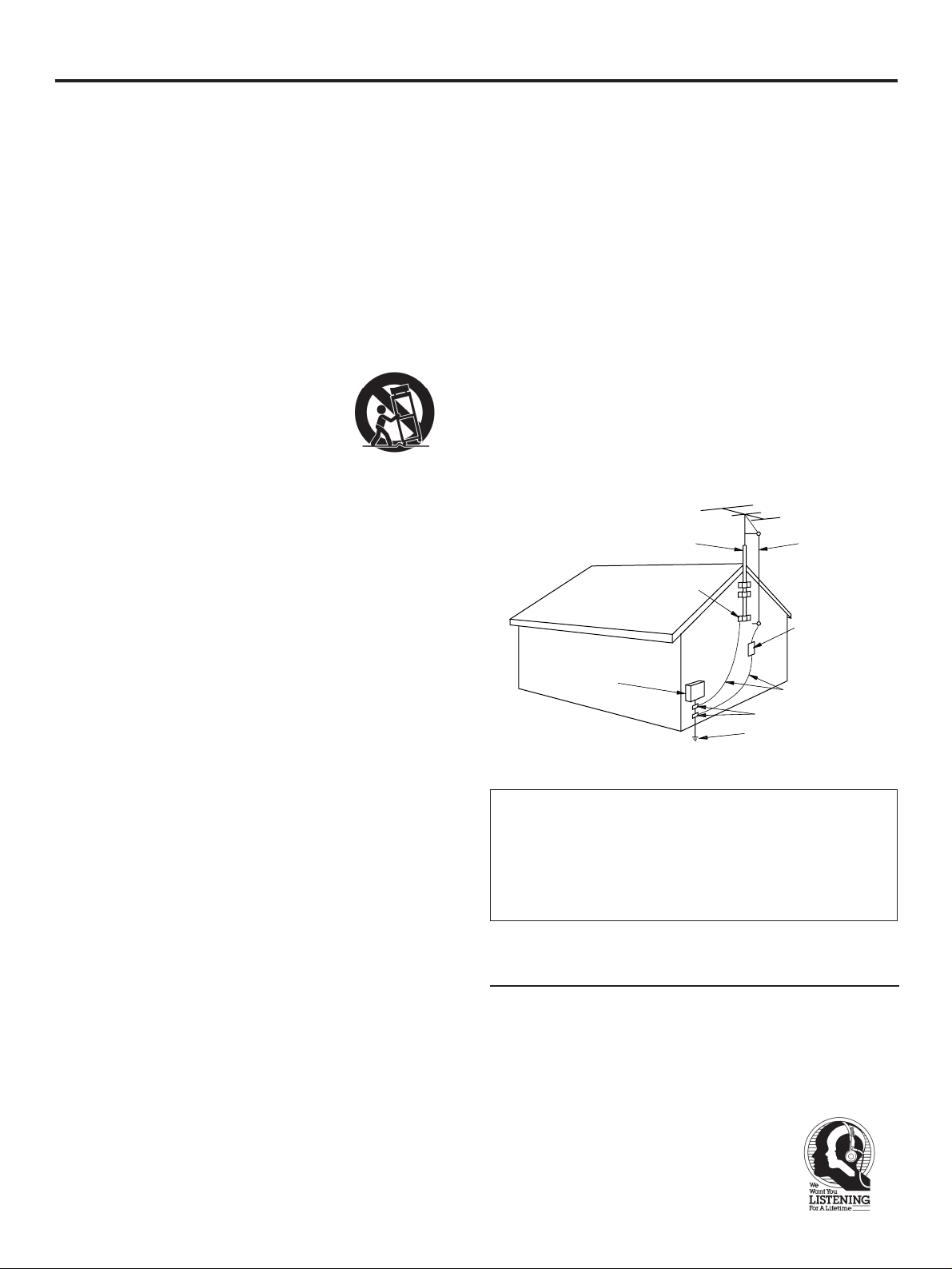
6 Carts and Stands – The unit should be used only with a
cart or stand that is recommended by the manufacturer.
6A A unit and cart combination should
be moved with care. Quick stops,
excessive force, and uneven
surfaces may cause the unit and
cart combination to overturn.
7 Wall or Ceiling Mounting – The unit
should be mounted to a wall or ceiling only as
recommended by the manufacturer.
8 Ventilation – The unit should be situated so that its location
or position does not interfere with its proper ventilation.
For example, the unit should not be situated on a bed,
sofa, rug, or similar surface, that may block the ventilation
openings; or placed in a built-in installation, such as a
bookcase or cabinet that may impede the flow of air
through the ventilation openings.
9 Heat – The unit should be situated away from heat sources
such as radiators, stoves, or other appliances that produce
heat.
10 Power Sources – The unit should be connected to a power
supply only of the type described in the operating
instructions or as marked on the unit.
11 Power-Cord Protection – Power-supply cords should be
routed so that they are not likely to be walked on or
pinched by items placed upon or against them, paying
particular attention to cords at plugs, convenience
receptacles, and the point where they exit from the unit.
12 Cleaning – The unit should be cleaned only as
recommended by the manufacturer.
13 Nonuse Periods – The power cord of the unit should be
unplugged from the outlet when left unused for a long
period of time.
14 Object and Liquid Entry – Care should be taken so that
objects do not fall into and liquids are not spilled into the
inside of the unit.
15 Damage Requiring Service – The unit should be serviced
by qualified service personnel when:
A. The power-supply cord or the plug has been damaged;
or
B. Objects have fallen, or liquid has been spilled into the unit;
or
C. The unit has been exposed to rain; or
D. The unit does not appear to operate normally or exhibits a
marked change in performance; or
E. The unit has been dropped, or the cabinet damaged.
16 Servicing – The user should not attempt to service the unit
beyond those means described in the operating
instructions. All other servicing should be referred to
qualified service personnel.
17 Power Lines – An outdoor antenna should be located away
from power lines.
18 Grounding or Polarization – Precautions should be taken
so that the grounding or polarization is not defeated.
19 Outdoor Antenna Grounding – If an outside antenna is
connected to this unit, be sure the antenna system is
grounded so as to provide some protection against voltage
surges and built-up static charges. Article 810 of the
National Electrical Code, ANSI/NFPA 70, provides
information with regard to proper grounding of the mast
and supporting structure, grounding of the lead-in wire to
an antenna discharge unit, size of grounding conductors,
location of antenna discharge unit, connection to
grounding electrodes, and requirements for the grounding
electrode.
YAMAHA and the Electronic Industries Association’s Consumer
Electronics Group want you to get the most out of your
equipment by playing it at a safe level. One that lets the sound
come through loud and clear without annoying blaring or
distortion – and, most importantly, without affecting your
sensitive hearing. Since hearing damage from loud sounds is
often undetectable until it is too late, YAMAHA
and the Electronic Industries Association’s
Consumer Electronics Group recommend you
to avoid prolonged exposure from excessive
volume levels.
We Want You Listening For A Lifetime
SAFETY INSTRUCTIONS
Note to CATV system installer:
This reminder is provided to call the CATV system
installer's attention to Article 820-40 of the NEC that
provides guidelines for proper grounding and, in
particular, specifies that the cable ground shall be
connected to the grounding system of the building, as close
to the point of cable entry as practical.
EXAMPLE OF ANTENNA GROUNDING
ANTENNA
LEAD IN
WIRE
ANTENNA
DISCHARGE UNIT
(NEC SECTION 810–20)
GROUNDING CONDUCTORS
(NEC SECTION 810–21)
GROUND CLAMPS
ELECTRIC
SERVICE
EQUIPMENT
NEC – NATIONAL ELECTRICAL CODE
MAST
GROUND
CLAMP
POWER SERVICE GROUNDING
ELECTRODE SYSTEM
(NEC ART 250. PART H)
3
1. IMPORTANT NOTICE : DO NOT MODIFY THIS UNIT!
This product, when installed as indicated in the
instructions contained in this manual, meets FCC
requirements. Modifications not expressly approved by
Yamaha may void your authority, granted by the FCC, to
use the product.
2. IMPORTANT : When connecting this product to
accessories and/or another product use only high quality
shielded cables. Cable/s supplied with this product
MUST be used. Follow all installation instructions.
Failure to follow instructions could void your FCC
authorization to use this product in the USA.
3. NOTE : This product has been tested and found to
comply with the requirements listed in FCC Regulations,
Part 15 for Class “B” digital devices. Compliance with
these requirements provides a reasonable level of
assurance that your use of this product in a residential
environment will not result in harmful interference with
other electronic devices.
This equipment generates/uses radio frequencies and, if
not installed and used according to the instructions
found in the users manual, may cause interference
harmful to the operation of other electronic devices.
Compliance with FCC regulations does not guarantee that
interference will not occur in all installations. If this product
is found to be the source of interference, which can be
determined by turning the unit “OFF” and “ON”, please try
to eliminate the problem by using one of the following
measures:
Relocate either this product or the device that is being
affected by the interference.
Utilize power outlets that are on different branch (circuit
breaker or fuse) circuits or install AC line filter/s.
In the case of radio or TV interference, relocate/reorient the
antenna. If the antenna lead-in is 300 ohm ribbon lead,
change the lead-in to coaxial type cable.
If these corrective measures do not produce satisfactory
results, please contact the local retailer authorized to
distribute this type of product. If you can not locate the
appropriate retailer, please contact Yamaha Electronics
Corp., U.S.A. 6660 Orangethorpe Ave, Buena Park, CA
90620.
The above statements apply ONLY to those products
distributed by Yamaha Corporation of America or its
subsidiaries.
FCC INFORMATION (U.S.A.)
1. This unit is a sophisticated AM/FM stereo tuner. To assure
proper operation and the best possible performance,
please read this manual carefully.
2. Choose the installation location for the unit carefully.
Avoid placing it in direct sunlight or close to a source of
heat. Also avoid locations subject to vibration and
excessive dust, heat, cold or moisture. Keep it away from
such sources of hum as transformers or motors.
3. Do not open the cabinet, because this may result in
damage to the unit or electrical shock. If a foreign object
should get into the unit, contact your local dealer.
4. To prevent lightning damage, disconnect the AC power
plug and disconnect the antenna cable when there is an
electrical storm.
5. When disconnecting the power plug from the wall outlet,
always pull directly on the plug; never pull the cord itself.
6. Do not use force when operating switches and other
controls.
7. When moving the unit, be sure to first disconnect the
power plug and disconnect all wires connected from the
unit to other equipment.
8. Do not attempt to clean this unit with chemical solvents,
because this may damage the finish. Use a clean, dry
cloth.
9. Be sure to read the “TROUBLESHOOTING” section of this
manual for advice on common operating errors before
concluding that the unit is faulty.
10.Keep this manual in a safe place for future reference.
CAUTION: READ THIS BEFORE OPERATING YOUR UNIT
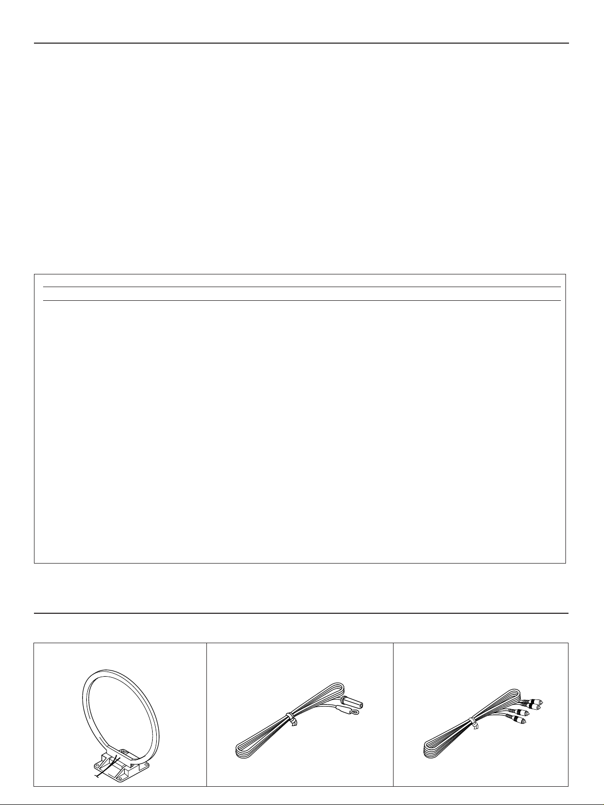
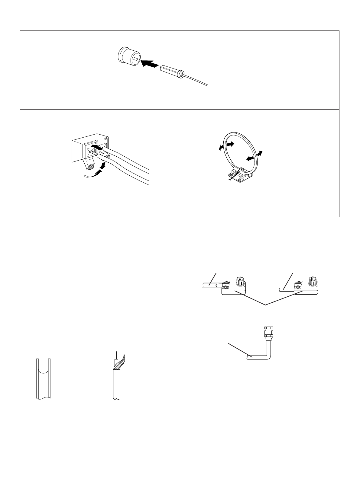
SUPPLIED ACCESSORIES
After unpacking, check that the following parts are contained.
AM Loop Antenna Indoor FM Antenna Audio connection cord
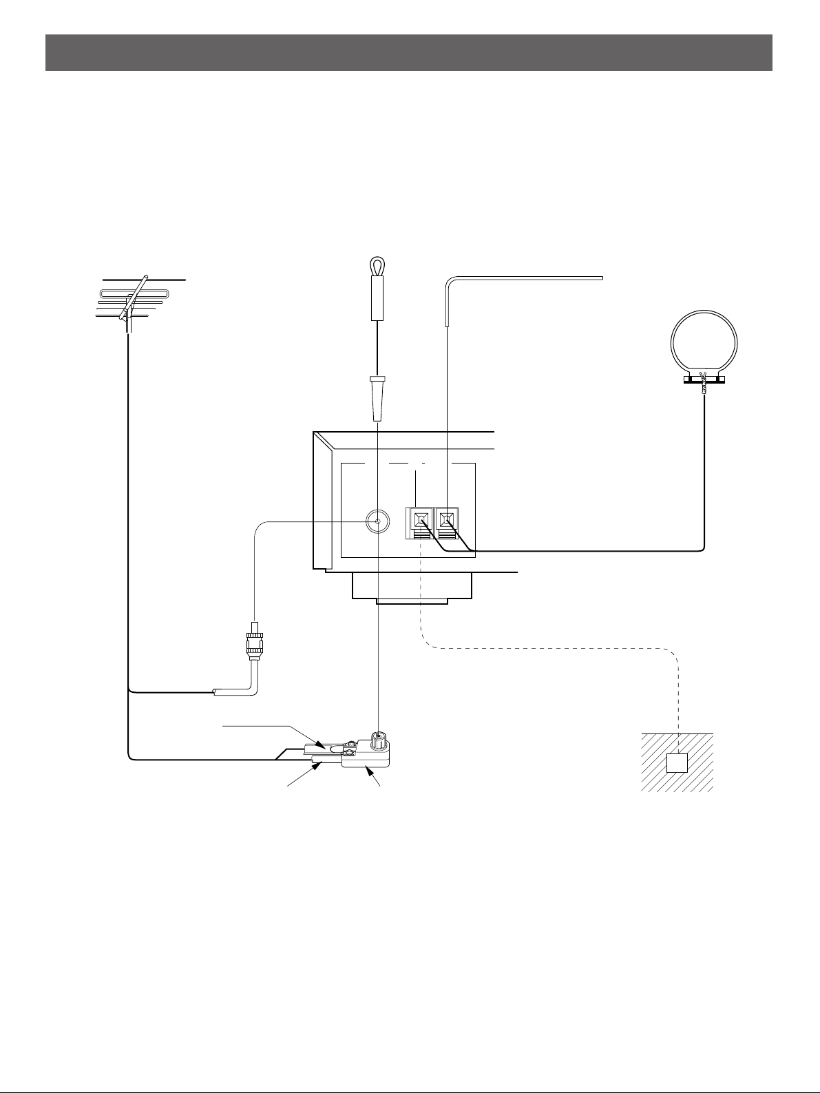
ANTENNA CONNECTIONS
●
Each antenna should be connected to the designated terminals correctly, referring to the following figure.
●
Both AM and FM indoor antennas are included with this unit. In general, these antennas will probably provide sufficient signal
strength. Nevertheless, a properly installed outdoor antenna will give clearer reception than an indoor one. If you experience
poor reception quality, an outdoor antenna may result in improvement.
4
CONNECTIONS
75Ω UNBAL.
FM ANT GND AM ANT
Outdoor FM antenna
Outdoor AM antenna
AM loop
antenna
(included)
Ground
75-ohm
antenna
adapter
Indoor FM
antenna
(included)
75-ohm/300-ohm
antenna adapter
75-ohm
coaxial cable
300-ohm
feeder
m Optional outdoor FM antenna
Consult with your dealer or authorized service center about the
best method of selecting and erecting an outdoor FM antenna.
The choice of the feeder cable is also important. Flat ribbonshaped twin-lead cable performs well electrically, and is
cheaper and somewhat easier to handle when routing it
through windows and around rooms. Coaxial cable is more
expensive, does a much better job of minimizing interference,
is less prone to the effects of weather and close-by metal
objects, and is nearly as good a signal conductor as feeder
cable, particularly for foam-type coaxial cables. Coaxial cable
is somewhat more difficult to install at the point where the
cable enters the building. If coaxial cable is selected, make
sure the antenna is designed to be used with that type of
cable.
* Use a 75-ohm/300-ohm antenna adapter (not included) or a
75-ohm antenna adapter (not included) for connections.
300-ohm feeder cable 75-ohm coaxial cable
75-ohm/300-ohm antenna adapter
Notes for FM antenna installation
●
To minimize automobile ignition noise, locate the antenna
as far from heavy traffic as possible.
●
Keep the feeder cable or coaxial cable as short as possible.
Do not bundle or roll up excess cable.
●
The antenna should be at least two meters (6.6 feet) from
reinforced concrete walls or metal structures.
5
Connecting the indoor FM antenna
*If you connect an outdoor FM antenna to this unit, do not connect the indoor FM antenna to this unit.
Connecting the AM loop antenna
Orient so that the best
reception is obtained.
* The AM loop antenna should be placed apart from the main unit. The antenna may be hung on a wall.
* The AM loop antenna should be kept connected, even if an outdoor AM antenna is connected to this unit.
1
3
2
300-ohm feeder
cable
75-ohm coaxial
cable
75-ohm antenna
adapter
75-ohm coaxial
cable
m Optional outdoor AM antenna
In steel buildings or at a great distance from the transmitter, it
may be necessary to install an outside long wire antenna.
GND terminal
For maximum safety and minimum interference, connect
the GND terminal to a good earth ground. A good earth
ground is a metal stake driven into moist earth.
6
CONNECTIONS TO THE AMPLIFIER
●
Before making any connections, switch OFF the power to
this unit and the amplifier or other component.
●
Be sure that the connections from the left (“L”) and right
(“R”) OUTPUT terminals are connected to the
corresponding (left and right) input terminals of the amplifier
or other component.
*This unit has a remote control sensor. It receives signals
from a remote control transmitter provided with a YAMAHA
amplifier.
OUTPUT
RL
TUNER
L
R
75Ω UNBAL.
FM ANT GND AM ANT
Amplifier
Connection cord (included)
This unit
To AC outlet
Remote control sensor
 Loading...