

Yamaha TX-396-L Service manual
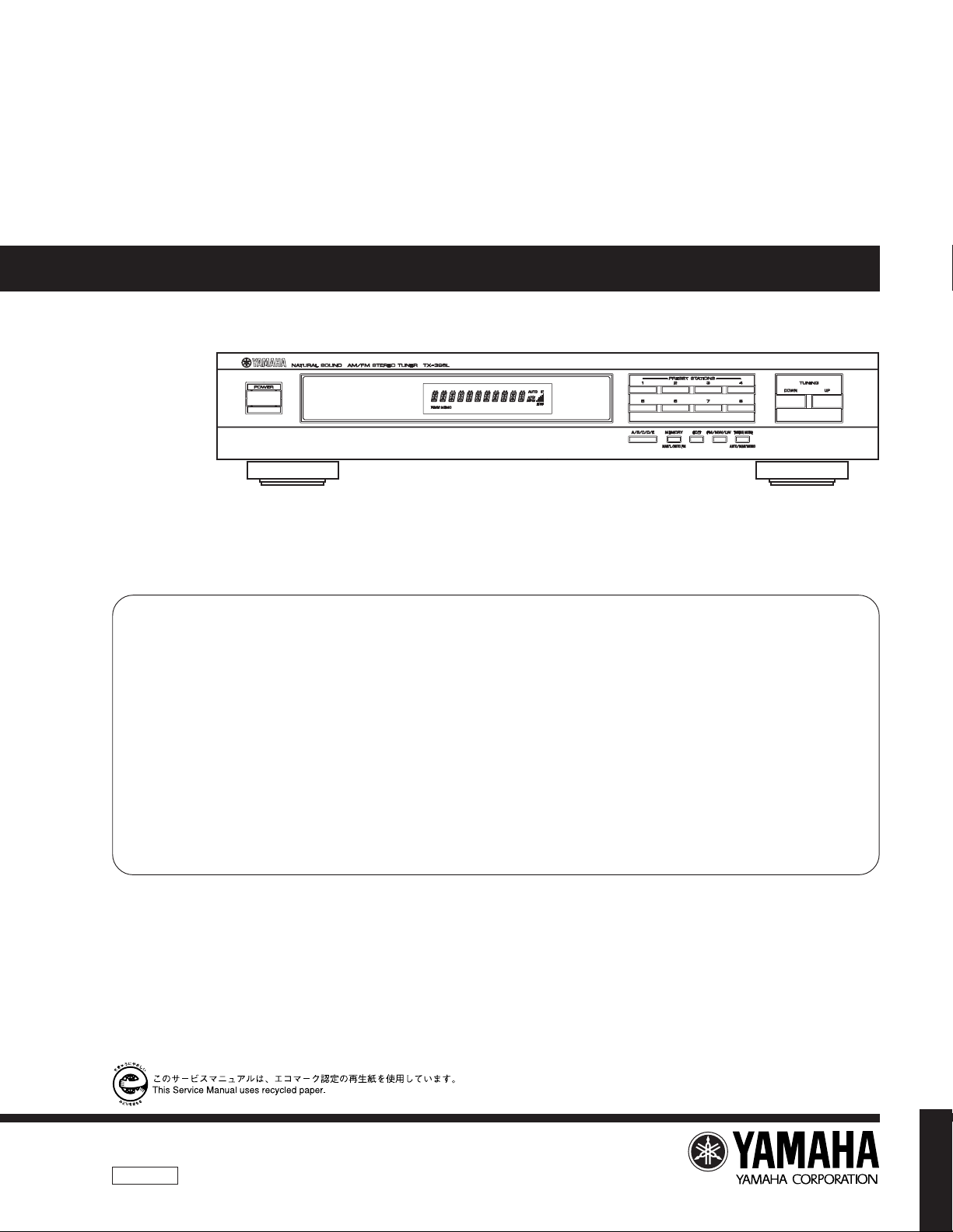
TX-396L
P.O.Box 1, Hamamatsu, Japan
AM/FM STEREO TUNER
TX-396L
SERVICE MANUAL
IMPORTANT NOTICE
This manual has been provided for the use of authorized YAMAHA
Retailers and their service personnel.
It has been assumed that basic service procedures inherent to the industry,
and more specifically YAMAHA Products, are already known and
understood by the users, and have therefore not been restated.
WARNING: Failure to follow appropriate service and safety
procedures when servicing this product may result in
personal injury, destruction of expensive components,
and failure of the product to perform as specified. For
these reasons, we advise all YAMAHA product owners
that any service required should be performed by an
authorized YAMAHA Retailer or the appointed service
representative.
IMPORTANT: The presentation or sale of this manual to any individual
or firm does not constitute authorization, certification or
recognition of any applicable technical capabilities, or
establish a principle-agent relationship of any form.
■ CONTENTS
TO SERVICE PERSONNEL .......................................... 1
SPECIFICATIONS .......................................................... 1
INTERNAL VIEW ........................................................... 2
REAR PANELS .............................................................. 2
DISASSEMBLY PROCEDURES ................................... 2
ADJUSTMENTS ......................................................... 3~7
The data provided is believed to be accurate and applicable to the unit(s)
indicated on the cover. The research, engineering, and service departments
of YAMAHA are continually striving to improve YAMAHA products.
Modifications are, therefore, inevitable and specifications are subject to
change without notice or obligation to retrofit. Should any discrepancy
appear to exist, please contact the distributor's Service Division.
WARNING: Static discharges can destroy expensive components.
Discharge any static electricity your body may have
accumulated by grounding yourself to the ground buss in
the unit (heavy gauge black wires connect to this buss).
IMPORTANT: Turn the unit OFF during disassembly and part
replacement. Recheck all work before you apply power
to the unit.
µCOM DATA .................................................................. 8
DISPLAY DATA ............................................................. 9
BLOCK DIAGRAM ................................................. 10~11
PRINTED CIRCUIT BOARD .................................. 12~13
SCHEMATIC DIAGRAM ........................................ 14~15
PARTS LIST ........................................................... 16~21
100700
TX-396L
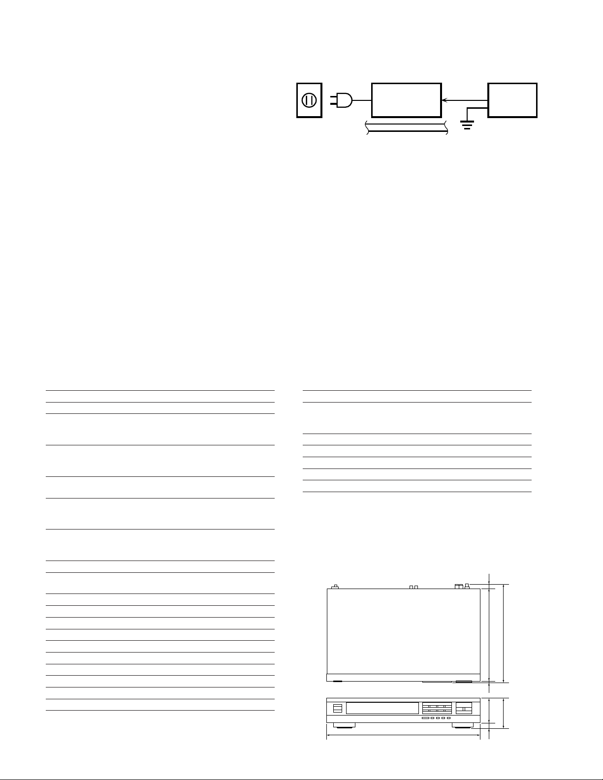
TX-396L
WALL
OUTLET
EQUIPMENT
UNDER TEST
AC LEAKAGE
TESTER OR
EQUIVALENT
INSULATING
TABLE
■ TO SERVICE PERSONNEL
Critical Components Information.
Components having special characteristics are marked
and must be replaced with parts having specifications
equal to those originally installed.
WARNING: CHEMICAL CONTENT NOTICE!
The solder used in the production of this product contains LEAD. In addition, other electrical/electronic and /or plastic
(where applicable) components may also contain traces of chemicals found by the California Health and Welfare Agency
(and possibly other entities) to cause cancer and/or birth defects or other reproductive harm.
DO NOT PLACE SOLDER, ELECTRICAL/ELECTRONIC OR PLASTIC COMPONENTS IN YOUR MOUTH FOR ANY REASON WHATSOEVER!
Avoid prolonged, unprotected contact between solder and your skin! When soldering, do not inhale solder fumes or expose
eyes to solder/flux vapor!
If you come in contact with solder or components located inside the enclosure of this product, wash your hands before
handling food.
■ SPECIFICATIONS
■ FM SECTION
Tuning Range 87.50 to 108.00 MHz
50dB Quieting Sensitivity (IHF)
Mono 1.55 µV(15.1 dBf)
Stereo (1 kHz 100% MOD) 21 µV(37.7 dBf)
Usable Sensitivity (DIN)
Mono (S/N 26 dB) 0.9 µV
Stereo (S/N 46 dB) 24 µV
Alternate Channel Selectivity
Selectivity (two signals) 40 kHz Dev. ±300 kHz 70 dB
Signal to Noise Ratio (DIN-Weighted 40 kHz)
Mono 75 dB
Stereo 70 dB
Harmonic Distortion 1 kHz
Mono 0.1 %
Stereo 0.2 %
Stereo Separetion 1kHz (40 kHz Dev.) 50 dB
Frequency Response
20 Hz to 15 kHz 0±0.5 dB
■ MW SECTION
Tuning Range 531 to 1611 kHz
Usable Sensitivity 200 µV/m
Signal to Noise Ratio 50 dB
Harmonic Distortion 1 kHz 0.3 %
■ LW SECTION
Tuning Range 153 to 288 kHz
Usable Sensitivity 400 µV/m
Signal to Noise Ratio 50 dB
Harmonic Distortion 1 kHz 0.3 %
■ AUDIO SECTION
Output Level/Impedance (Fixed)
FM 100 % MOD 1 kHz 500 mV/2.2 kΩ
MW/LW 30 % MOD 1 kHz 200 mV/2.2 kΩ
■ GENERAL
Power Supply AC230V, 50Hz
Power Consumption 7 W
Dimensions (W x H x D) 435 x 86 x 278mm
Weight 3.2 kg
* Specifications subject to change without notice.
• MODEL COLOR
Black and Gold
• DIMENSIONS
27886
263.5 11.33.27016
435
1
34 5 6
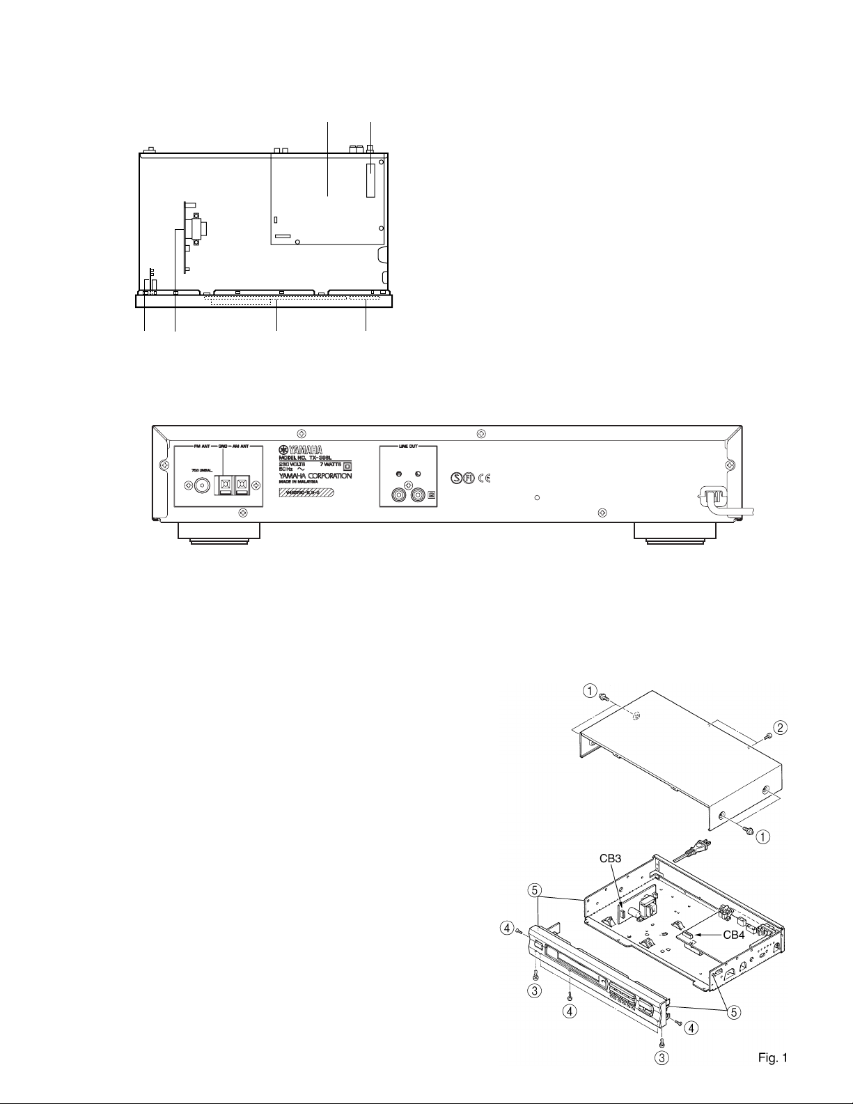
■ INTERNAL VIEW
TX-396L
■ REAR PANEL
1
2
1 Tuner P. C. B (1)
2 Front-end pack
3 Operation P. C. B. (2)
4 Tuner P. C. B. (2)
5 Operation P. C. B. (1)
6 Operation P. C. B. (3)
■ DISASSEMBLY PROCEDURES
(Remove parts in the order as numbered.)
1. Removal of Top Cover
Remove 4 screws (1) and 2 screws (2) in Fig. 1.
2. Removal of Front Panel
a. Disconnect the connectors (CB3 anf CB4) in Fig. 1.
b. Remove 2 plastic rivets (3) in Fig. 1.
c. Remove 5 screws (4) in Fig. 1.
d. Unhook at 2 place (5) in Fig. 1.
2
TX-396L
FM
SG
Oscilloscope
ACVM
DIST. M
FM
ANT
L
R
OUT
PUT
GND
FM
dummy
antenna
Tuner
P. C. B.
FM
SG
Oscilloscope
ACVM
DIST. M
FM
ANT
L
R
YLF-15
(LPF)
OUT
PUT
GND
FM
dummy
antenna
Tuner
P. C. B.
SSG
FM
SG
Oscilloscope
ACVM
DIST. M
FM
ANT
L
R
OUT
PUT
GND
FM
dummy
antenna
Tuner
P. C. B.
oscillator
FM
SG
DCVM
FM
ANT
TP1
TP2
R51
GND
FM
dummy
antenna
Tuner
P. C. B.
oscillator
■ ADJUSTMENTS
1. Before Adjustment
(1)With the power turned on, wait for 5 minutes before
starting adjustment so that operation becomes stable.
(2)Adjust the OSC coil and IFT with insulated screwdriver.
(3)Set the TUNING MODE to AUTO.
(4)Decibel abbreviations
dBµ : Decibels above or below 1µV
Example :
0dBµ = 1 µv, 60dBµ = 1 mV
X dBµ = (X + 11.2) dBf
When substituting 60 for X,
60 dBµ = 72.2 dBf
2. Measuring instrument abbreviations
FM SG : FM signal generator
SSG : Stereo signal generator
AM SG : AM signal generator
DIST. M : Distortion meter
FC : Frequency counter
ACVM : AC voltage meter
DCVM : DC voltage meter
(1)All the segments on the display light up.
(2)The model name, TX-396L is displayed.
(3)The place of destination is displayed.
(4)The µCOM-version is displayed.
Pressing the P1 key will cause operation to start from (1).
Pressing any other key will cause the mode to return to the
NORMAL mode.
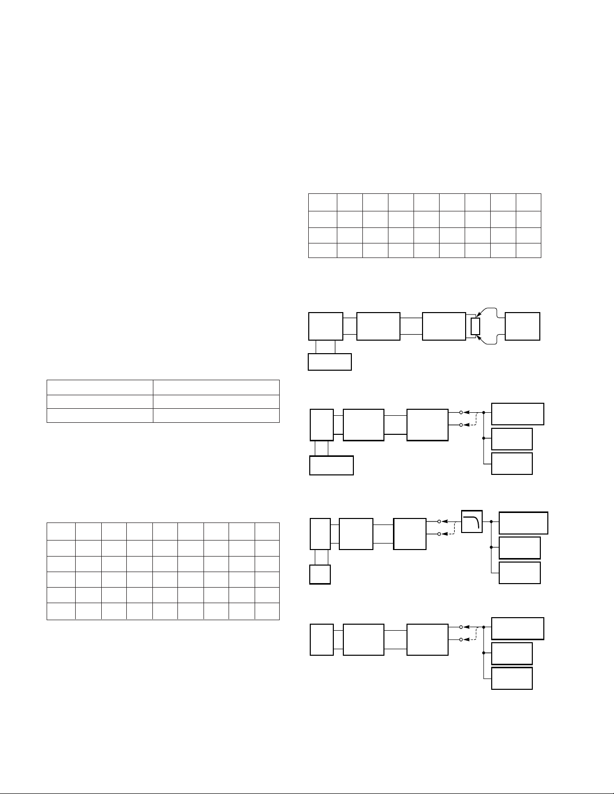
<Factory preset memory content>
Preset
A, E 87.50 90.10 95.10 98.10 108.00 88.10 106.10 108.00
B, D 630 1080 1440 531 1611 900 1350 1404
P1 P2 P3 P4 P5 P6 P7 P8
C 153 171 225 270 288 180 207 252
<Connection Diagram (Measuring Instruments)>
1) Discriminator balance adjustment
<POWER SUPPLY CHECK>
Check that the voltage obtained across each test point
and ground on the tuner circuit is as follows.
Test points Rating or Standard
+5 V terminal +5.6 ±0.5 V
-VP terminal -23.0 ±1.0 V
CAUTION :
Before setting to the TEST mode, write down the user
preset memory content in the table as shown below. (This
is because setting to the TEST mode will cause the
memory content to be the factory preset memory content,
i.e. all the user preset memory content will be erased.)
<User preset memory content>
Preset keys
P1 P2 P3 P4 P5 P6 P7 P8
A
B
C
D
E
2) Monaural distortion adjustment
3) Stereo distortion adjustment
4) Sensitivity verification
<TEST mode>
• Turn on the POWER switch while pressing the A/B/C/D/
E and FM/AM(FM/MW/LW) keys simultaneously, and
the unit enters the TEST mode for the display check.
After this, repeat (1) to (4).
3
D
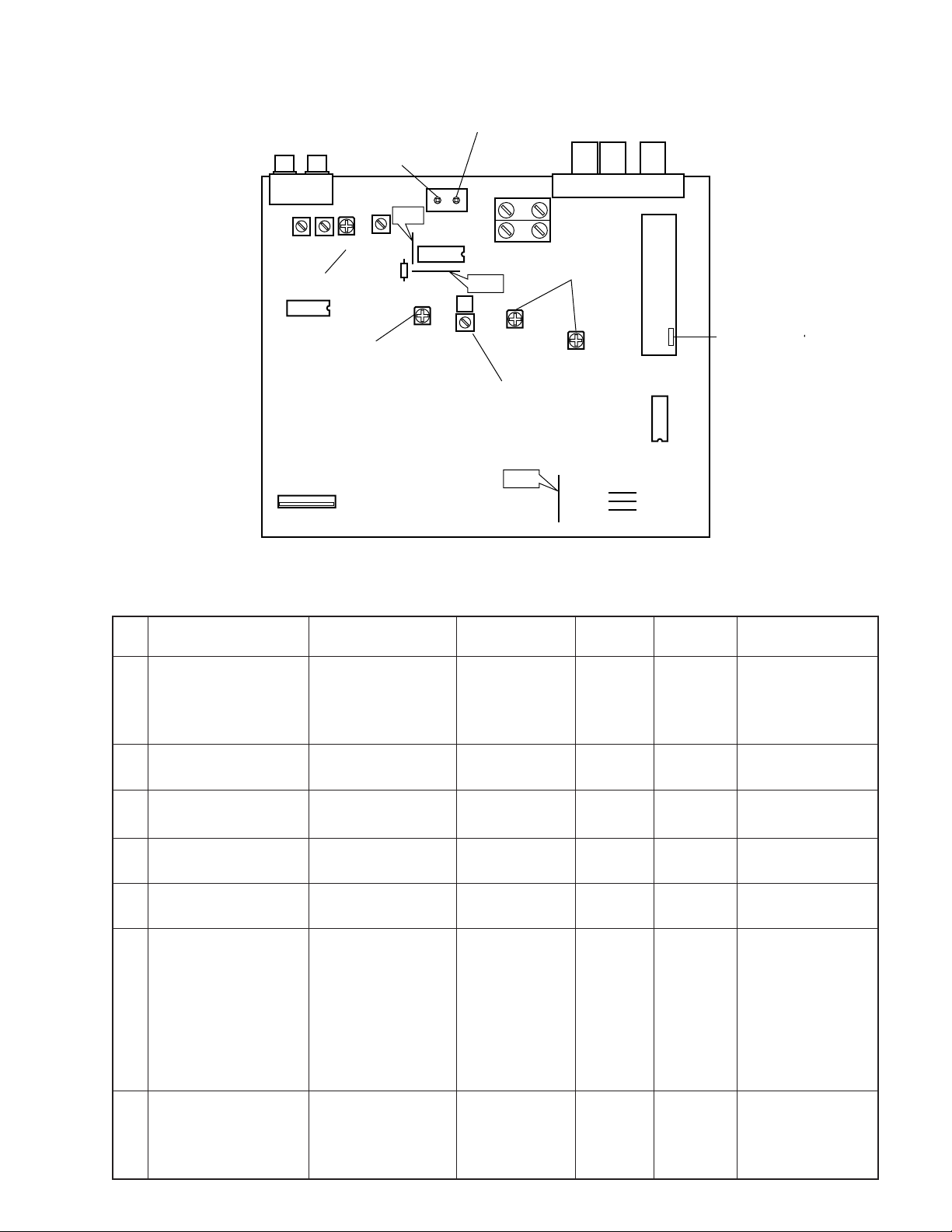
● TEST POINTS
DISCRIMINATOR
J6
BALANCE
L8
J7
TP2
PK2
STEREO
DISTORTION
PK1
LINEOUT AMANT GND FMANT
LR
MONAURAL
DISTORTION
TP1
L13 L12 VR4
L10
R51
SEPARATION
TX-396L
<FM TUNER SECTION>
Step
Adjustment item
Rough adjustment of
discriminator balance.
1
Rough adjustment of
2
monaural distortion.
SIGNAL
VR3
METER
Signal (ANT IN)
FM SG:
98.1 MHz 70 dBµ
Modulation : 100 %
Monaural : 1 kHz
Same as Step 1.
VR2
L5
AMSENSITIVITY
TP3
J73
Reception
frequency
Preset
A-4: 98.1 MHz
Same as Step 1.
VR1
Adjusted
point
L8
(right side)
L8
(left side)
Test point
TP1, TP2
(both end
of R51)
OUTPUT
FRONTEN
IFT
Rating
DC 0 V ±100mV
at tuning point.
Minimize distortion.
Fine adjustment of
3
discriminator balance.
Fine adjustment of
4
monaural distortion.
Verification of
5
discriminator balance.
Adjustment of frontend
IFT.
6
Adjustment of stereo
distortion.
7
Same as Step 1.
Same as Step 1.
Same as Step 1.
FM SG:
98.1 MHz 30 dBµ
Modulation : 100 %
Monaural : 1 kHz
FM SG:
98.1 MHz 70 dBµ
Modulation : 100 %
Stereo L or R : 1 kHz
Same as Step 1.
Same as Step 1.
Same as Step 1.
Same as Step 1.
Same as Step 1.
L8
(right side)
L8
(left side)
Frontend
IFT
VR1, VR2
TP1, TP2
OUTPUT
TP1, TP2
TP3, GND
OUTPUT
DC 0 V ±50mV
Minimize distortion.
(to less than 0.7%)
DC 0 V ±50mV
Adjust so that the
DC voltage is
maximum.
CAUTION:
If IFT core is turned
excessively, the
sensitivity reduces.
(Maximum ±90°)
Minimize distortion.
Tuning mode is
AUTO.
4

TX-396L
Step
8
9
10
11
Adjustment item
Verification of monaural
distortion.
Verification of stereo
distortion.
Verification of
sensitivity.
Adjustment of
separation.
Signal (ANT IN)
FM SG:
98.1 MHz 70 dBµ
Modulation : 100 %
Monaural : 1 kHz
FM SG:
98.1 MHz 70 dBµ
Modulation : 100 %
Stereo L or R : 1 kHz
FM SG:
88.1/98.1/106.1 MHz
Modulation : 100 %
Monaural : 1 kHz
FM SG:
98.1 MHz 70 dBµ
Modulation : 100 %
Stereo L or R : 1 kHz
Reception
frequency
Same as Step 1.
Same as Step 1.
A-6: 88.1 MHz
A-4: 98.1 MHz
A-7: 106.1 MHz
Preset
A-4: 98.1 MHz
Adjusted
point
VR4
Test point
OUTPUT
OUTPUT
OUTPUT
Rating
Minimize distortion.
(to less than 0.7%)
Minimize distortion.
(to less than 1.4%)
Tuning mode is
AUTO.
S/N should be 30 dB
at each frequency of
88.1 MHz, 98.1 MHz
and 106.1 MHz.
Make sure that the
voltage at the ANT
terminal is 7 dBµ or
less.
To more than 35 dB.
Tuning mode is
AUTO.
Adjustment of the signal
meter.
12
Verification of the signal
meter to turn off.
13
Verification of AUTO
TUNING.
14
FM SG:
98.1 MHz 45 dBµ
Modulation : 30 %
Monaural : 1 kHz
ANT input minimum.
FM SG:
98.1 MHz 23 dBµ
Modulation : 30 %
Stereo L or R : 1 kHz
Preset
A-4: 98.1 MHz
Preset
A-4: 98.1 MHz
VR3
Tuning
buttons
Signal
meter
Adjust so that the
signal meter is
maximum at rating
level.
Make sure that the
signal meter is
turned off.
Automatic reception
should be available
when the tuning UP
or DOWN key is
pressed.
Stereo indicator is
turned on.
Audio muting should
be applied during
tuning.
5
 Loading...