

Page 1
TG500
MIDI DATA FORMAT
1.Synthesizer mode
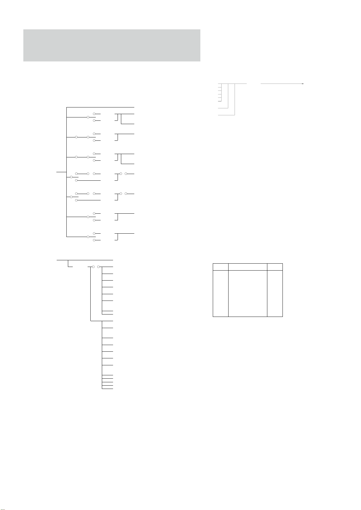
1. MIDI reception/transmission block diagram
<MIDI reception conditions> 1/2
Rch ---- Voice Receive ch.
VCE,PFM
< Rch >
<each ch>
MULTI
VCE,PFM
MULTI
VCE,PFM
MULTI
PLAY MODE
on
PLAY MODE
on
VCE,PFM
MULTI
VCE,PFM
MULTI
Bulk Protect
off
< Rch >
<each ch>
< Rch >
<each ch>
Program Change
< Rch >
<each ch>
Program Change
< Rch >
<each ch>
< Rch >
<each ch>
< Rch >
<each ch>
$F0,$43,$10,$29,$08,$00
$F0,$43,$0n,$7A NORMAL VOICE bulk
(LM__0065VC)
$F0,$43,$0n,$7A DRUM VOICE bulk
(LM__0065DR)
$F0,$43,$0n,$7A PERFORMANCE bulk
(LM__0065PF)
$F0,$43,$0n,$7A SONG(MULTI) bulk
(LM__0065MU)
$F0,$43,$0n,$7A SYNTH SETUP bulk
(LM__0066SY)
$F0,$43,$0n,$7A Sample bulk(SY99)
(LM__0040SA)
$F0,$7E,$cc,$01 Dump Header
$F0,$7E,$cc,$02 Data Packet
$F0,$43,$1n,$29,$xx Parameter change
$F0,$43,$1n,$04,$40 Parameter change
$F0,$43,$2n,$7A VOICE bulk D.req.
(LM__0065VC)
$F0,$43,$2n,$7A
(LM__0065PF)
$F0,$43,$2n,$7A MULTI bulk D.req.
(LM__0065MU)
$F0,$43,$2n,$7A Synth Setup bulk D.req.
(LM__0066SY)
$F0,$43,$2n,$7A 1 Sample bulk D.req.
(LM__0040SA)
$F0,$7E,$cc,$03 Dump Request
$F0,$7E,$cc,$7C Wait
$F0,$7E,$cc,$7D Cancel
$F0,$7E,$cc,$7E NAK
$F0,$7E,$cc,$7F ACK
Poly AT FLT
Control chg.
FLT
MIDI
VCE,PFM
MULTI
VCE,PFM
MULTI
<MIDI reception conditions> 2/2
MIDI
≠off
<Dev No>
on
on
$FE ACTIVE SENSING
$8n NOTE OFF
$9n NOTE ON/OFF
$An POLY AFTER TOUCH
$Bn,$00 controllers
↓↓
↓↓
$Bn,$78 ↓
$Bn,$20
$Bn,$00 BANK SELECT
I, C, and P are switched.
$Cn PROGRAM CHANGE
I, C, and P are not switched
$Dn AFTER TOUCH
$En PITCH BENDER
SW REMOTE
Sample Dump Standard
(Master Tuning)
PERFORMANCE bulk D.req.
Sample Dump Standard
<MIDI transmission conditions>
Voice bulk
Performance bulk
Multi bulk
Synth setup bulk
Sample bulk
Sample dump standard
Parameter change
Sample Dump Request
2. Channel message
2.1 Reception
2.1.1 Note Off
Reception note range = C-2...G8
Velocity range = Not received
2.1.2 Note On/Off
Reception note range = C-2...G8
Velocity range = 0...127
2.1.3 Polyphonic After Touch
Polyphonic After Touch is received when it is set to on during
system setup.
Reception note range = E0...G6
If the received note exceeds the above range, the effect is applied
to the maximum and minimum note values.
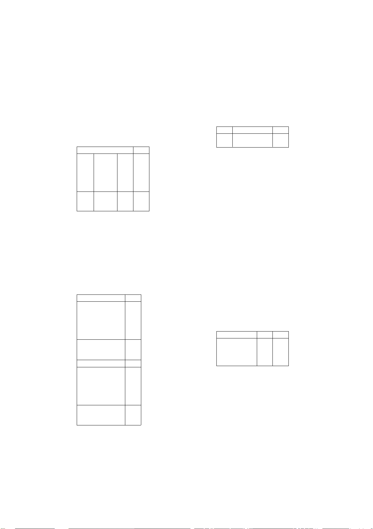
2.1.4 Control change
The parameters in the table below can be controlled by MIDI.
cntrl parameter data rng
10 Pan* 0 〜 127
16 Effect Control 1 0 〜 127
17 Effect Control 2 0 〜 127
18 MIDI Control 3 0 〜 127
19 MIDI Control 4 0 〜 127
0 〜 119 Volume 0 〜 127
0 〜 120 MIDI Control 1 0 〜 127
0 〜 120 MIDI Control 2 0 〜 127
0 〜 120 MIDI Control 3 (add) 0 〜 127
0 〜 120 MIDI Control 4 (add) 0 〜 127
0 〜 120 Effect Control 1 (add) 0 〜 127
0 〜 120 Effect Control 2 (add) 0 〜 127
64 Sustain Switch 0, 127
* Pan is received only when MULTI is generated.
<Dev No>
≠off
MIDI
Dev No = Device Number
1
Page 2
2.1.5 Program change
When a program change is received, the TG500 performs the
following operations.
Three reception mode types can be set during the system setup.
1) off : Program change is not received.
2) normal
: In each play mode, the program No. changes in
accordance with 00〜63 of the current mode .
The program bank change is not received.
Program change Nos. are assigned as follows in
accordance with the mode.
Data (dec.)
Voice Internal1 0〜63 00〜63
Internal2 0〜63 00〜63
Preset1 0〜63 00〜63
Preset2 0〜63 00〜63
Preset3 0〜63 00〜63
Preset4 0〜63 00〜63
Card1 0〜63 00〜63
Card2 0〜63 00〜63
Card3 0〜63 00〜63
Card4 0〜63 00〜63
Perfor Internal1 0〜63 00〜63
-mance Preset1 0〜63 00〜63
Preset2 0〜63 00〜63
Card1 0〜63 00〜63
Card2 0〜63 00〜63
3) direct
: In voice mode, voice 00〜63 correspond to the
program change data 00〜63. INT1, 2, PRE 1-4,
and CARD1-4 change in accordance with the
program bank change.
Program change data 64〜127 are not received.
In performance mode, performance 00〜63
correspond to the program change data 00〜63.
INT1, PRE1, 2, and Card 1, 2 change in
accordance with the program bank change.
Program change data 64〜127 are not received.
In Multi mode, each INST program changes in
accordance with the above.
Program bank change Nos. are assigned as
follows in accordance with the mode.
Bn 00 xx 20 xx Data (dec.)
Internal1 Voice 00,00
Internal2 Voice 00,03
Preset1 Voice 00,02
Preset2 Voice 00,05
Preset3 Voice 00,08
Preset4 Voice 00,11
Card1 Voice 00,01
Card2 Voice 00,04
Card3 Voice 00,07
Card4 Voice 00,10
Internal1 Performance 00,64
Preset1 Performance 00,66
Preset2 Performance 00,69
Card1 Performance 00,65
Card2 Performance 00,68
Internal1 Multi 00,16
Internal1 Voice(multi) 00,32
Internal2 Voice(multi) 00,35
Preset1 Voice (multi) 00,34
Preset2 Voice (multi) 00,37
Preset3 Voice (multi) 00,40
Preset4 Voice (multi) 00,43
Card1 Voice(multi) 00,33
Card2 Voice(multi) 00,36
Card3 Voice(multi) 00,39
Card4 Voice(multi) 00,42
Internal1 Perf(multi) 00,80
Preset1 Perf (multi) 00,82
Preset2 Perf (multi) 00,85
Card1 Perf(multi) 00,81
Card2 Perf(multi) 00,84
2.1.6 Pitch bend
Pitch bend is received only on the MSB side.
2.1.7 After touch
After touch is received in accordance with the reception channel
of each mode.
2.1.8 Channel mode message
cntrl# Parameter data rng
120 All Sound Off 0
121 Reset All Controller 0
123 All Notes Off 0
3. System exclusive message
3.1 Parameter change
The TG500 transmits and receives the following eight parameter change
types.
(7) Remote switch is received only.)
7) Remote switch will be the same as the screen when the switch is
pressed.。
1). Multi Data
2). Performance Data
3). Normal Voice Data
4). Drum Voice Data
5). Setup Data
6). Program Change Table
7). Switch Remote
8). Master Tuning
The parameter change reception cannot be turned off with the MIDI
switches, except for Device Number off.
3.1.1 TG500 Data parameter change
(1) Format
11110000 F0
01000011 43
0001nnnn nnnn = Device Number
00101001 29
0000gggg gggg = Parameter Group Number
0sssssss sssssss = Parameter Sub Group Number
0ppppppp ppppppp = Parameter Number MS7bit
0ppppppp ppppppp = Parameter Number LS7bit
0vvvvvvv vvvvvvv = Data Value MS7bit
0vvvvvvv vvvvvvv = Data Value LS7bit
11110111 F7
(2) Parameter Group Number,Sub Group Number
Parameter Group Name gggg sssssss
Multi Data 0 0,1..16 *1
Performance Data 1 0,1..4 *2
Normal Voice Data 2 0 *3
Drum Voice Data 3 0,36..84 *4
Setup Data 4 0 *5
Program Change Table 7 0..63 *6
Switch Remote 8 0
*1:1..16;Inst Number,0;common data
*2:1..4;Layer Number,0;common data
*3:0=Voice
*4:36..84=Key Number,0;common data
*5:0=syn
*6:Program Number
(3) Parameter Number,Data Value
See the appended table 1.
4) table
: Reception is carried out in accordance with the
PROGRAM CHANGE TABLE.
2
Page 3

(4) Operation
(Transmission)
When the data is edited with the panel switch, the parameter
change is transmitted in accordance with the previously stated
transmission conditions.
(Reception)
1)〜4)
The TG500 has three sound generation modes: Voice, Performance and Multi. Only when the sound generation mode of the
transmitting side and receiving side match, Reception is possible.
The mode on the receiving side does not change and the page does
not change. However, the data display will be updated.
5)〜6)
All modes: Modes are received as they are (no page change.)
7)
This parameter change is only for reception. Remote control is
possible with all panel switches. This message has the same effect
as pressing the switch.
(2) Data Format Name
Bulk Dump Type ddddddd ttttttt mmmmmmm
Normal Voice 0065VC *1 0..62
Drum Voice 0065DR *2 63
Performance 0065PF *3 0..63
Multi(Song) 0065MU 0 0..9
Synthesizer Setup 0066SY 0 0
Sample 0040SA 0 0..63
*1:0=int1,3=int2,127=edit_buffer
*2:0=int1,3=int2,127=edit_buffer
*3:0=int1,127=edit_buffer
*4:When memory number exceeds the upper limit, it is handled as an upper limit value
during bulk reception, and it is ignored during dump request reception.
*5: When a memory type is not defined during bulk dump reception;
with 4)〜7), it is ignored and handled as int.
with 1) and 2),
=127 edit_buffer
=0〜2 int1
=3〜7 int2
=other bit3〜bir7 are ignored and the above process is performed
with 3),
=127 edit_buffer
=0〜2 int1
=other bit 2〜bit7 are ignored and the above process is performed.
3.1.2 Master Tuning parameter change
(1) Format
11110000 F0
01000011 43
0001nnnn nnnn = Device Number
00101001 04
01000000 40
0vvvvvvv vvvvvvv = Data Value
11110111 F7
(2) Operation
(Transmission)
When the master tune data is edited with the panel switch, the
parameter change is transmitted in accordance with the previously
stated transmission conditions.
(Reception)
All modes: Modes are received as they are. (no page change)
4. Bulk dump
The TG500 transmits and receives the following 7 bulk dump types.
Reception is not possible during performance and recording.
Transmission is performed when MIDI UTILITY "bulk dump" is executed,
or when a dump request is received.
1). Normal Voice bulk dump
2). Drum Voice bulk dump
3). Performance bulk dump
4). Multi bulk dump
5). Synthesizer Setup bulk dump
6). Sample bulk dump
(1) Format
0 11110000 F0
1 01000011 43
2 0000nnnn nnnn=Device Number
3 01111010 7A
4 0bbbbbbb
5 0bbbbbbb
6 01001100 4C(ascii"L")
7 01001101 4D(ascii"M")
8 00100000 20(ascii" ")
9 00100000 20(ascii" ")
10 0ddddddd ddddddd=Data Format Name(ascii)
11 0ddddddd ddddddd=Data Format Name(ascii)
12 0ddddddd ddddddd=Data Format Name(ascii)
13 0ddddddd ddddddd=Data Format Name(ascii)
14 0ddddddd ddddddd=Data Format Name(ascii)
15 0ddddddd ddddddd=Data Format Name(ascii)
16 00000000 00
↓ ↓↓
29 00000000 00
30 0ttttttt ttttttt=Memory_type
31 00mmmmmm mmmmmmm=Memory Number
32 0vvvvvvv vvvvvvv=data value
↓ ↓↓
0sssssss sssssss=check_sum
11110111 F7
4 and 5 are not available during a Dump Request and 32 becomes "F7".
C
H
E
C
K
S
U
M
No. of bytes
(3) Data Format
See the appended table 1.
(4) Operation
(Transmission)
While being transmitted with the BULK UTILITY using 1)〜4),
during All Voices Bulk transmission
VOICE
Memory_type = 00(INT1)
Memory Number =Transmission is carried out up to 63 starting from 0 sequentially.
Memory_type = 03(INT2)
Memory Number =Transmission is carried out up to 63 starting from 0 sequentially.
during All Performance Bulk transmission,
PERFORMANCE
Memory_type = 00(INT1)
Memory Number =Transmission is carried out up to 63 starting from 0 sequentially.
during All Multi Bulk transmission,
MULTI
Memory_type = 00(INT)
Memory Number =Transmission is carried out up to 15 starting from 0 sequentially.
5 Sample Dump
For the sample dump the TG500 uses the Sample Dump Standard and the
SY99 Sample Bulk Dump.
Both of them can be received.
For transmission, the above two data types are transmitted successively when
"Sample Dump of Sample Utility" is executed. When receiving Sample
Dump Standard Dump Request, and the SY99 Sample Bulk Dump Request,
each data type is transmitted.
With the Sample Dump Standard and the SY99 Sample Bulk Dump, $1f is
the upper limit of the Sample (memory) Number; numbers exceeding this are
handled as $1f.
Sample Dump Standard
DUMP REQ F0,7E,cc,03,ss,ss,F7
ACK F0,7E,cc,7F,pp,F7
NAK F0,7E,cc,7E,pp,F7
CANCEL F0,7E,cc,7D,pp,F7
WAIT F0,7E,cc,7C,pp,F7
DATA PACKET F0,7E,cc,02,kk,<120 byte>,ll,F7
DUMP HEADER F0,7E,cc,01,ss,ss,ee,ff,ff,ff,gg,gg,gg,hh,hh,hh
,ii,ii,ii,jj,F7
pp : packet number
cc : channel number
ss ss : sample number (LSB first)
ee : sample format (SY99 handles 8〜16 bits.)
ff ff ff : sample period (LSB first)
gg gg gg : sample length (LSB first)
hh hh hh : loop start (LSB first)
ii ii ii : loop end (LSB first)
jj : loop type (00=normal Loop,01=alternate Loop,7F=Loop off)
kk : running packet count(0-127)(Sequential packet No.)
ll : checksum(XOR of 7E cc 02 kk <120 bytes>)
6. Status FE (Active sensing)
a)Reception
If a signal is not output from MIDI for longer than approximately 300 msec
after receiving FE, the MIDI reception buffer is cleared, and if key on
remains it is turned off.
3
Page 4

< Table 1 >
(1) MIDI Parameter Change table ( Multi )
$F0,$43,$1n,$29,$00,sub_group,p_msb,p_lsb,v_msb,v_lsb,$F7
Note)n ; Device Number
s;parameter sub_group number
p; parameter number
v; parameter value
[MULTI PARAMETERS]
1. COMMON s=0
PARAMETER BULK PARAM DATA DISP
reserved
effect mode
effect1 type
effect2 type
effect control1 parameter
effect control1 add controller
effect control2 parameter
effect control2 add controller
effect control2 min limit
effect control2 max limit
effect1 parameter1
effect1 parameter2
effect1 parameter3
effect1 parameter4
effect1 parameter5
effect1 parameter6
effect1 parameter7
effect1 parameter8
effect1 level-a
effect1 level-b
effect2 parameter1
effect2 parameter2
effect2 parameter3
effect2 parameter4
effect2 parameter5
effect2 parameter6
effect2 parameter7
effect2 parameter8
effect2 level-a
effect2 level-b
effect mix level
effect balance out1
effect balance out2
effect control1 min limit
effect control1 max limit
effect lfo wave
effect lfo speed
effect lfo delay time
effect insert 1b
effect insert 2a
NUMBER NUMBER RANGE
0 ― 0
110..2 off,seri,para
220..90 0..90
330..90 0..90
440..31 off..Ef_Ins2b
550..124 0..124
660..31 off..Ef_Ins2b
770..124 0..124
880..100 0..100
990..100 0..100
10 10 0..??? ???
|110..??? ???
| Not in order 12 0..??? ???
|130..??? ???
|140..??? ???
|150..??? ???
|160..??? ???
33 17 0..??? ???
34 18 0..100 0..100
35 19 0..100 0..100
36 20 0..??? ???
|210..??? ???
| Not in order 22 0..??? ???
|230..??? ???
|240..??? ???
|250..??? ???
|260..??? ???
59 27 0..??? ???
60 28 0..100 0..100
61 29 0..100 0..100
62 30 0..100 0..100
63 31 0..100 0..100
64 32 0..100 0..100
65 33 0..100 0..100
66 34 0..100 0..100
67 35 0..6 tri..1tm
68 36 0..99 0..99
69 37 0..99 0..99
70 38 0..100 0..100
71 39 0..100 0..100
(To be continued)
4
Page 5

PARAMETER BULK PARAM DATA DISP
effect insert 2b 72 40 0..100 0..100
multi name top 73 49 32..127 ASCII
multi name | 74 50 32..127 ASCII
multi name | 75 51 32..127 ASCII
multi name | 76 52 32..127 ASCII
multi name | 77 53 32..127 ASCII
multi name | 78 54 32..127 ASCII
multi name | 79 55 32..127 ASCII
multi name bottom 80 56 32..127 ASCII
reserved 81 ― 0
reserved 82 ― 0
reserved 83 ― 0
reserved 84 ― 0
reserved 85 ― 0
reserved 86 ― 0
reserved 87 ― 0
reserved 88 ― 0
reserved 89 ― 0
reserved 90 ― 0
reserved 91 ― 0
reserved 92,93 ― 0
2. INST s=1..16(inst number)
PARAMETER BULK PARAM DATA DISP
inst memory bank 94,95 0 b0,1 1..4
inst memory b2,3 int/crd/ pre
off/on for ind1..4 b4..b7 0..1
inst voice number 96,97 1 b0..5 0..63
inst v,p select b6 pfm/vce
inst switch b7 off,on
inst volume 98 2 0..127 0..127
inst tune 99 3 1..127 +-63
inst note shift 100 4 1..127 +-63
inst pan 101 5 b0..b5 +-31
inst pan source b6=0,1 multi,vce/pfm
off/on for send1..4 102 6 b0..3 0..1
off/on for out1,2 b4..5 0..1
off/on for vce send b6 0..1
inst effect send 103 7 0..127 0..127
NUMBER NUMBER RANGE
NUMBER NUMBER RANGE
104..113
114..123
124..133
134..143
144..153
154..163
164..173
174..183
184..193
194..203
(To be continued)
5
Page 6

PARAMETER BULK PARAM DATA DISP
NUMBER NUMBER RANGE
204..213
214..223
224..233
234..243
244..253
(2) MIDI Parameter Change table ( Performance )
$F0,$43,$1n,$29,$01,sub_group,p_msb,p_lsb,v_msb,v_lsb,$F7
Note)n ; Device Number
s;parameter sub group number
p; parameter number
v; parameter value
1. COMMON s=0
PARAMETER BULK PARAM DATA DISP
NUMBER NUMBER RANGE
reserved 0 ― 0
effect mode 1 1 0..2 off,seri,par
effect1 type 2 2 0..90 0..90
effect2 type 3 3 0..90 0..90
effect control1 parameter 4 4 0..31 off..Ef_Ins2b
effect control1 add controller 5 5 0..124 0..124
effect control2 parameter 6 6 0..31 off..Ef_Ins2b
effect control2 add controller 7 7 0..124 0..124
effect control2 min limit 8 8 0..100 0..100
effect control2 max limit 9 9 0..100 0..100
effect1 parameter1 10 10 0..??? ???
effect1 parameter2 | 11 0..??? ???
effect1 parameter3 | Not in order 12 0..??? ???
effect1 parameter4 | 13 0..??? ???
effect1 parameter5 | 14 0..??? ???
effect1 parameter6 | 15 0..??? ???
effect1 parameter7 | 16 0..??? ???
effect1 parameter8 33 17 0..??? ???
effect1 level-a 34 18 0..100 0..100
effect1 level-b 35 19 0..100 0..100
effect2 parameter1 36 20 0..??? ???
effect2 parameter2 | 21 0..??? ???
effect2 parameter3 | Not in order 22 0..??? ???
effect2 parameter4 | 23 0..??? ???
effect2 parameter5 | 24 0..??? ???
effect2 parameter6 | 25 0..??? ???
effect2 parameter7 | 26 0..??? ???
effect2 parameter8 59 27 0..??? ???
effect2 level-a 60 28 0..100 0..100
effect2 level-b 61 29 0..100 0..100
effect mix level 62 30 0..100 0..100
effect balance out1 63 31 0..100 0..100
effect balance out2 64 32 0..100 0..100
effect control1 min limit 65 33 0..100 0..100
effect control1 max limit 66 34 0..100 0..100
(To be continued)
6
Page 7

PARAMETER BULK PARAM DATA DISP
effect lfo wave 67 35 0..6 tri..1tm
effect lfo speed 68 36 0..99 0..99
effect lfo delay time 69 37 0..99 0..99
effect insert 1b 70 38 0..100 0..100
effect insert 2a 71 39 0..100 0..100
effect insert 2b 72 40 0..100 0..100
performance name top 73 49 32..127 ASCII
performance name | 74 50 32..127 ASCII
performance name | 75 51 32..127 ASCII
performance name | 76 52 32..127 ASCII
performance name | 77 53 32..127 ASCII
performance name | 78 54 32..127 ASCII
performance name | 79 55 32..127 ASCII
performance name bottom 80 56 32..127 ASCII
reserved 81 ― 0
reserved 82 ― 0
performance total level 83 59 0..127 0..127
2. LAYER s=1..4(layer number)
PARAMETER BULK PARAM DATA DISP
layer memory bank 84,85 0 b0,b1 1..4
reserved b2 0
layer memory b3 int(card)/ pre
reserved b4..b7 0
layer voice number 86,87 1 0..62 0..62
layer switch b7 off,on
layer volume 88 2 0..127 0..127
layer detune 89 3 b0..b3 -7..+7
MC3,4 enable b4,5 off/on
layer note shift 90 4 1..127 -63..+63
layer pan 91 5 0..63 -31..+31
off/on for send1..4 92 6 b0..3 off/on
off/on for out1,2 b4..5 off/on
layer effect send 93 7 0..127 0..127
layer effect send velocity sensitivity
layer effect send scaling b4..b7 -7..+7
layer note limit low 96 9 0..127 C-2..G8
layer note limit high 97 10 0..127 C-2..G8
layer velocity limit low 98 11 1..127 1..127
layer velocity limit high 99 12 1..127 1..127
layer AEG R1 100,101 13 0..255 -63..+63
layer AEG D1R 102,103 14 0..255 -63..+63
layer AEG D2R 104,105 15 0..255 -63..+63
layer AEG RR 106,107 16 0..255 -63..+63
layer AEG velocity sensitivity 108,109 17 0..255 -14..+14
layer filter cutoff 110,111 18 0..255 -127..+127
layer filter velocity sensitivity 112,113 19 0..255 -127..+127
layer filter resonance 114,115 20 0..255 -99..+99
layer LFO speed 116,117 21 0..255 -99..+99
NUMBER NUMBER RANGE
NUMBER NUMBER RANGE
94,95 8 b0..b3 -7..+7
(To be continued)
7
Page 8

PARAMETER BULK PARAM DATA DISP
layer LFO depth 118,119 22 0..255 -99..+99
layer AT use 120,121 23 b0,1,2 off,use a,b,c,d
reserved b3 0
layer MIDI Control1 use b4,5,6 off,use a,b,c,d
reserved b7 0
layer MIDI Control2 use 122,123 24 b0,1,2 off,use a,b,c,d
reserved b3 0
layer PEG switch b4 off/on
layer sustain switch b5 off/on
fixed mode note# 124,125 25 0..127 C-2..G8
frequency fix switch b7 normal/fix
reserved 126 0
(3) MIDI Parameter Change table ( Normal Voice )
$F0,$43,$1n,$29,$02,$00,p_msb,p_lsb,v_msb,v_lsb,$F7
Note)n ; Device Number
p; parameter number
v; parameter value
NUMBER NUMBER RANGE
127..169
170..212
213..255
PARAMETER BULK PARAM DATA DISP
reserved 0 ― 0
effect mode 1 1 0..2 off,seri,para
effect1 type 2 2 0..90 0..90
effect2 type 3 3 0..90 0..90
effect control1 parameter 4 4 0..28 off..LFO dly
effect control1 add controller 5 5 0..124 0..124
effect control2 parameter 6 6 0..28 off..LFO dly
effect control2 add controller 7 7 0..124 0..124
effect control2 min limit 8 8 0..100 0..100
effect control2 max limit 9 9 0..100 0..100
effect1 parameter1 10 10 0..??? ???
effect1 parameter2 | 11 0..??? ???
effect1 parameter3 | Not in order 12 0..??? ???
effect1 parameter4 | 13 0..??? ???
effect1 parameter5 | 14 0..??? ???
effect1 parameter6 | 15 0..??? ???
effect1 parameter7 | 16 0..??? ???
effect1 parameter8 33 17 0..??? ???
effect1 level-a 34 18 0..100 0..100
effect1 level-b 35 19 0..100 0..100
effect2 parameter1 36 20 0..??? ???
effect2 parameter2 | 21 0..??? ???
effect2 parameter3 | Not in order 22 0..??? ???
effect2 parameter4 | 23 0..??? ???
effect2 parameter5 | 24 0..??? ???
effect2 parameter6 | 25 0..??? ???
NUMBER NUMBER RANGE
(To be continued)
8
 Loading...