

Page 1

Yamaha L2 Switch
SWP2 series (SWP2-10SMF, SWP2-10MMF)
Command Reference
Rev.2.03.06
Page 2

2 | Command Reference | TOC
Contents
Preface: Introduction ............................................................................................11
Chapter 1: How to read the command reference ...............................................12
1.1 Applicable firmware revision .....................................................................................................................12
1.2 How to read the command reference ..........................................................................................................12
1.3 Interface names ...........................................................................................................................................
1.4 Input syntax for commands starting with the word "no" ............................................................................13
Chapter 2: How to use the commands .................................................................14
2.1 Operation via console .................................................................................................................................14
2.2 Operation via configuration (config) files ..................................................................................................16
2.3 Login ...........................................................................................................................................................17
2.4 Command input mode ................................................................................................................................17
2.5 Keyboard operations when using the console ............................................................................................18
2.6 Commands that start with the word "show" ...............................................................................................20
12
2.1.1 Access from a console terminal ...................................................................................................14
2.1.2 Access from a TELNET client ....................................................................................................14
2.1.3 Access from an SSH client ..........................................................................................................15
2.1.4 Console terminal/VTY settings ...................................................................................................15
2.2.1 Access from a TFTP client ..........................................................................................................16
2.2.2 Reading/writing a configuration file ...........................................................................................16
2.4.1 Command input mode basics .......................................................................................................17
2.4.2 individual configuration mode ....................................................................................................18
2.4.3 Command prompt prefix .............................................................................................................18
2.4.4 Executing commands of a different input mode ..........................................................................18
2.5.1 Basic operations for console input ..............................................................................................19
2.5.2 Command help .............................................................................................................................19
2.5.3 Input command completion and keyword candidate list display ................................................20
2.5.4 Entering command abbreviations ................................................................................................20
2.5.5 Command history ........................................................................................................................20
2.6.1 Modifiers .....................................................................................................................................20
Chapter 3: Configuration .....................................................................................22
3.1 Manage setting values ................................................................................................................................22
3.2 Default setting values .................................................................................................................................22
Chapter 4: Maintenance and operation functions .............................................28
4.1 Passwords ...................................................................................................................................................28
4.1.1 Set password for unnamed user ...................................................................................................28
4.1.2 Set administrator password ..........................................................................................................28
4.1.3 Encrypt password ........................................................................................................................29
4.1.4 Allow login with special password ..............................................................................................29
4.2 User account maintenance ..........................................................................................................................30
4.2.1 Set user password ........................................................................................................................30
4.2.2 Show login user information .......................................................................................................31
4.2.3 Set banner ....................................................................................................................................32
4.3 Configuration management ........................................................................................................................33
4.3.1 Save running configuration .........................................................................................................33
4.3.2 Save running configuration .........................................................................................................33
4.3.3 Save certain functions to the backup configuration ....................................................................33
4.3.4 Show the running configuration ..................................................................................................34
Page 3

Command Reference | TOC | 3
4.3.5 Show startup configuration ..........................................................................................................35
4.3.6 Show backup configuration .........................................................................................................35
4.3.7 Erase startup configuration ..........................................................................................................36
4.3.8 Erase backup of certain functions ................................................................................................36
4.4 Manage boot information ...........................................................................................................................36
4.4.1 Show boot information ................................................................................................................36
4.4.2 Clear boot information ................................................................................................................37
4.5 Show unit information ................................................................................................................................37
4.5.1 Show inventory information ........................................................................................................
4.5.2 Show operating information ........................................................................................................38
4.5.3 Show currently-executing processes ...........................................................................................39
4.5.4 Show technical support information ............................................................................................39
4.6 Time management ......................................................................................................................................40
4.6.1 Set clock manually ......................................................................................................................40
4.6.2 Set time zone ...............................................................................................................................40
4.6.3 Show current time ........................................................................................................................41
4.6.4 Set NTP server .............................................................................................................................41
4.6.5 Synchronize time from NTP server (one-shot update) ................................................................42
4.6.6 Synchronize time from NTP server (update interval) .................................................................42
4.6.7 Show NTP server time synchronization settings .........................................................................43
4.7 Terminal settings ........................................................................................................................................43
4.7.1 Move to line mode (console terminal) .........................................................................................43
4.7.2 Set VTY port and move to line mode (VTY port) ......................................................................44
4.7.3 Set terminal login timeout ...........................................................................................................44
4.7.4 Change the number of lines displayed per page for the terminal in use ......................................45
4.7.5 Set the number of lines displayed per page on the terminal ........................................................45
4.8 Management ...............................................................................................................................................46
4.8.1 Set management VLAN ..............................................................................................................46
4.9 SYSLOG .....................................................................................................................................................46
4.9.1 Set log notification destination (SYSLOG server) ......................................................................46
4.9.2 Set log output level (debug) ........................................................................................................47
4.9.3 Set log output level (informational) ............................................................................................47
4.9.4 Set log output level (error) ..........................................................................................................47
4.9.5 Set log console output .................................................................................................................48
4.9.6 Back up log ..................................................................................................................................48
4.9.7 Clear log ......................................................................................................................................48
4.9.8 Show log ......................................................................................................................................49
4.10 SNMP .......................................................................................................................................................49
4.10.1 Set host that receives SNMP notifications ................................................................................49
4.10.2 Set notification type to transmit ................................................................................................50
4.10.3 Set system contact .....................................................................................................................51
4.10.4 Set system location ....................................................................................................................52
4.10.5 Set SNMP community ...............................................................................................................52
4.10.6 Set SNMP view .........................................................................................................................53
4.10.7 Set SNMP group ........................................................................................................................53
4.10.8 Set SNMP user ..........................................................................................................................54
4.10.9 Show SNMP community information .......................................................................................55
4.10.10 Show SNMP view settings ......................................................................................................56
4.10.11 Show SNMP group settings .....................................................................................................56
4.10.12 Show SNMP user settings .......................................................................................................56
4.11 RMON ......................................................................................................................................................57
4.11.1 Set RMON function ...................................................................................................................57
37
Page 4

4 | Command Reference | TOC
4.12 Telnet server .............................................................................................................................................65
4.13 Telnet client ..............................................................................................................................................67
4.14 TFTP server ..............................................................................................................................................68
4.15 HTTP server .............................................................................................................................................69
4.16 SSH server ................................................................................................................................................73
4.17 SSH client .................................................................................................................................................78
4.18 LLDP ........................................................................................................................................................79
4.11.2 Set RMON Ethernet statistical information group ....................................................................57
4.11.3 Set RMON history group ...........................................................................................................58
4.11.4 Set RMON event group .............................................................................................................59
4.11.5 Set RMON alarm group
4.11.6 Show RMON function status .....................................................................................................62
4.11.7 Show RMON Ethernet statistical information group status ......................................................63
4.11.8 Show RMON history group status ............................................................................................63
4.11.9 Show RMON event group status ...............................................................................................63
4.11.10 Show RMON alarm group status ............................................................................................64
4.11.11 Clear counters of the RMON Ethernet statistical information group ......................................64
4.12.1 Start Telnet server and change listening port number ...............................................................65
4.12.2 Show Telnet server settings .......................................................................................................65
4.12.3 Set host that can access the Telnet server ..................................................................................66
4.12.4 Restrict access to the TELNET server according to the IP address of the client ......................66
4.13.1 Start Telnet client ......................................................................................................................67
4.13.2 Enable Telnet client ...................................................................................................................67
4.14.1 Start TFTP server and change listening port number ................................................................68
4.14.2 Show TFTP server settings ........................................................................................................68
4.14.3 Set hosts that can access the TFTP server .................................................................................69
4.15.1 Start HTTP server and change listening port number ...............................................................69
4.15.2 Start secure HTTP server and change listening port number ....................................................70
4.15.3 Show HTTP server settings .......................................................................................................70
4.15.4 Set hosts that can access the HTTP server ................................................................................71
4.15.5 Restrict access to the HTTP server according to the IP address of the client ...........................71
4.15.6 Web GUI display language .......................................................................................................72
4.15.7 Set log-in timeout time for HTTP server ...................................................................................72
4.16.1 Start SSH server and change listening port number ..................................................................73
4.16.2 Show SSH server settings ..........................................................................................................74
4.16.3 Set host that can access the SSH server .....................................................................................74
4.16.4 Set client that can access the SSH server ..................................................................................74
4.16.5 Generate SSH server host key ...................................................................................................75
4.16.6 Clear SSH server host key .........................................................................................................76
4.16.7 Show SSH server public key .....................................................................................................76
4.16.8 Set SSH client alive checking ....................................................................................................77
4.17.1 Start SSH client .........................................................................................................................78
4.17.2 Enable SSH client ......................................................................................................................79
4.17.3 Clear SSH host information .......................................................................................................79
4.18.1 Enable LLDP function ...............................................................................................................79
4.18.2 Set system description ...............................................................................................................80
4.18.3 Set system name ........................................................................................................................80
4.18.4 Create LLDP agent ....................................................................................................................81
4.18.5 Set automatic setting function by LLDP ...................................................................................81
4.18.6 Set LLDP transmission/reception mode ....................................................................................82
4.18.7 Set type of management address ...............................................................................................82
4.18.8 Set basic management TLVs .....................................................................................................83
.............................................................................................................60
Page 5

Command Reference | TOC | 5
4.18.9 Set IEEE-802.1 TLV .................................................................................................................83
4.18.10 Set IEEE-802.3 TLV ...............................................................................................................84
4.18.11 Set LLDP-MED TLV ..............................................................................................................84
4.18.12 Set LLDP frame transmission interval ....................................................................................85
4.18.13 Set LLDP frame transmission interval for high speed transmission period ............................85
4.18.14 Set time from LLDP frame transmission stop until re-initialization .......................................86
4.18.15 Set multiplier for calculating time to live (TTL) of device information .................................86
4.18.16 Set number of LLDP frames transmitted during the high speed transmission period .............
4.18.17 Set maximum number of connected devices manageable by a port ........................................87
4.18.18 Show interface status ...............................................................................................................87
4.18.19 Show information for connected devices of all interfaces ......................................................90
4.18.20 Clear LLDP frame counters .....................................................................................................91
4.19 L2MS (Layer 2 management service) settings .........................................................................................92
4.19.1 Set L2MS control frame transmit/receive .................................................................................92
4.19.2 Show L2MS information ...........................................................................................................92
4.20 Snapshot ...................................................................................................................................................93
4.20.1 Set snapshot function .................................................................................................................93
4.20.2 Set whether to include terminals in the snapshot comparison ...................................................93
4.20.3 Create snapshot ..........................................................................................................................94
4.20.4 Delete snapshot ..........................................................................................................................94
4.21 Firmware update .......................................................................................................................................94
4.21.1 Set firmware update site ............................................................................................................94
4.21.2 Execute firmware update ...........................................................................................................95
4.21.3 Set firmware download timeout duration ..................................................................................95
4.21.4 Allow revision-down .................................................................................................................96
4.21.5 Show firmware update function settings ...................................................................................96
4.21.6 Set firmware update reload time ................................................................................................96
4.22 General maintenance and operation functions .........................................................................................97
4.22.1 Set host name .............................................................................................................................97
4.22.2 Reload system ............................................................................................................................97
4.22.3 Initialize settings ........................................................................................................................98
4.22.4 Set default LED mode ...............................................................................................................98
4.22.5 Show LED mode .......................................................................................................................98
4.22.6 Show DIP switches status ..........................................................................................................99
4.22.7 Show port error LED status .......................................................................................................99
86
Chapter 5: Interface control ..............................................................................100
5.1 Interface basic settings .............................................................................................................................100
5.1.1 Set description ...........................................................................................................................100
5.1.2 Shutdown ...................................................................................................................................100
5.1.3 Set speed and duplex mode .......................................................................................................100
5.1.4 Set MRU ....................................................................................................................................101
5.1.5 Set cross/straight automatic detection .......................................................................................102
5.1.6 Set EEE ......................................................................................................................................102
5.1.7 Show EEE capabilities ..............................................................................................................103
5.1.8 Show EEE status ........................................................................................................................103
5.1.9 Set port mirroring ......................................................................................................................104
5.1.10 Show port mirroring status ......................................................................................................105
5.1.11 Show interface status ...............................................................................................................106
5.1.12 Show brief interface status ......................................................................................................108
5.1.13 Show frame counter .................................................................................................................109
5.1.14 Clear frame counters ................................................................................................................111
5.1.15 Show SFP+ module status .......................................................................................................111
Page 6

6 | Command Reference | TOC
5.2 Link aggregation .......................................................................................................................................112
5.3 Port authentication ....................................................................................................................................122
5.4 Port security ..............................................................................................................................................139
5.1.16 Set SFP+ module optical reception level monitoring ..............................................................112
5.2.1 Set static logical interface ..........................................................................................................112
5.2.2 Show static logical interface status ............................................................................................113
5.2.3 Set LACP logical interface ........................................................................................................113
5.2.4 Show LACP logical interface status ..........................................................................................114
5.2.5 Set LACP system priority order ................................................................................................116
5.2.6 Show LACP system priority ......................................................................................................
5.2.7 Set LACP timeout ......................................................................................................................117
5.2.8 Clear LACP frame counters ......................................................................................................118
5.2.9 Show LACP frame counter .......................................................................................................118
5.2.10 Set load balance function rules ................................................................................................118
5.2.11 Show protocol status of LACP logical interface .....................................................................119
5.2.12 Set LACP port priority order ...................................................................................................121
5.3.1 Configuring the IEEE 802.1X authentication function for the entire system ...........................122
5.3.2 Configuring the MAC authentication function for the entire system ........................................122
5.3.3 Configuring the Web authentication function for the entire system .........................................123
5.3.4 Set operation mode for the IEEE 802.1X authentication function ............................................123
5.3.5 Set for forwarding control on an unauthenticated port for IEEE 802.1X authentication ..........124
5.3.6 Set the EAPOL packet transmission count ................................................................................124
5.3.7 Set the MAC authentication function ........................................................................................125
5.3.8 Set MAC address format during MAC authentication ..............................................................125
5.3.9 Set the Web authentication function ..........................................................................................126
5.3.10 Set host mode ..........................................................................................................................126
5.3.11 Set re-authentication ................................................................................................................127
5.3.12 Set dynamic VLAN .................................................................................................................128
5.3.13 Set the guest VLAN .................................................................................................................128
5.3.14 Suppression period settings following failed authentication ...................................................129
5.3.15 Set reauthentication interval ....................................................................................................129
5.3.16 Set the reply wait time for the RADIUS server overall ...........................................................130
5.3.17 Set supplicant reply wait time .................................................................................................130
5.3.18 Set RADIUS server host ..........................................................................................................131
5.3.19 Set the reply wait time for each RADIUS server ....................................................................131
5.3.20 Set number of times to resend requests to RADIUS server ....................................................132
5.3.21 Set RADIUS server shared password ......................................................................................132
5.3.22 Set time of RADIUS server usage prevention .........................................................................133
5.3.23 Show port authentication information .....................................................................................133
5.3.24 Show supplicant information ...................................................................................................134
5.3.25 Show statistical information ....................................................................................................135
5.3.26 Clear statistical information ....................................................................................................135
5.3.27 Show RADIUS server setting information ..............................................................................136
5.3.28 Settings for redirect destination URL following successful Web authentication ....................136
5.3.29 Clear the authentication state ...................................................................................................137
5.3.30 Setting the time for clearing the authentication state (system) ................................................137
5.3.31 Setting the time for clearing the authentication state (interface) .............................................138
5.3.32 Set EAP pass through ..............................................................................................................138
5.4.1 Set port security function ...........................................................................................................139
5.4.2 Register permitted MAC addresses ...........................................................................................139
5.4.3 Set operations used for security violations ................................................................................139
5.4.4 Show port security information .................................................................................................140
117
Page 7

Command Reference | TOC | 7
5.5 Error detection function ............................................................................................................................140
5.5.1 Set automatic recovery from errdisable state ............................................................................140
5.5.2 Show error detection function information ...............................................................................141
Chapter 6: Layer 2 functions .............................................................................142
6.1 FDB (Forwarding Data Base) ...................................................................................................................142
6.1.1 Set MAC address acquisition function ......................................................................................142
6.1.2 Set dynamic entry ageing time ..................................................................................................142
6.1.3 Clear dynamic entry ..................................................................................................................143
6.1.4 Set static entry ...........................................................................................................................143
6.1.5 Show MAC address table ..........................................................................................................144
6.2 VLAN .......................................................................................................................................................145
6.2.1 Move to VLAN mode ................................................................................................................145
6.2.2 Set VLAN interface ...................................................................................................................145
6.2.3 Set private VLAN ......................................................................................................................146
6.2.4 Set secondary VLAN for primary VLAN .................................................................................147
6.2.5 Set access port (untagged port) ..................................................................................................147
6.2.6 Set associated VLAN of an access port (untagged port) ...........................................................148
6.2.7 Set trunk port (tagged port) .......................................................................................................148
6.2.8 Set associated VLAN for trunk port (tagged port) ....................................................................149
6.2.9 Set native VLAN for trunk port (tagged port) ...........................................................................150
6.2.10 Set private VLAN port type ....................................................................................................151
6.2.11 Set private VLAN host port .....................................................................................................
6.2.12 Set promiscuous port for private VLAN .................................................................................152
6.2.13 Set voice VLAN ......................................................................................................................153
6.2.14 Set CoS value for voice VLAN ...............................................................................................154
6.2.15 Set DSCP value for voice VLAN ............................................................................................154
6.2.16 Set multiple VALN group .......................................................................................................155
6.2.17 Set name of multiple VLAN group .........................................................................................155
6.2.18 Show VLAN information ........................................................................................................156
6.2.19 Show private VLAN information ............................................................................................156
6.2.20 Show multiple VLAN group setting information ....................................................................157
6.3 STP (Spanning Tree Protocol) ..................................................................................................................157
6.3.1 Set spanning tree for the system ................................................................................................157
6.3.2 Set forward delay time ...............................................................................................................158
6.3.3 Set maximum aging time ...........................................................................................................158
6.3.4 Set bridge priority ......................................................................................................................159
6.3.5 Set spanning tree for an interface ..............................................................................................159
6.3.6 Set spanning tree link type ........................................................................................................160
6.3.7 Set interface BPDU filtering .....................................................................................................160
6.3.8 Set interface BPDU guard .........................................................................................................161
6.3.9 Set interface path cost ................................................................................................................162
6.3.10 Set interface priority ................................................................................................................162
6.3.11 Set edge port for interface .......................................................................................................163
6.3.12 Show spanning tree status .......................................................................................................163
6.3.13 Show spanning tree BPDU statistics .......................................................................................165
6.3.14 Clear protocol compatibility mode ..........................................................................................167
6.3.15 Move to MST mode .................................................................................................................167
6.3.16 Generate MST instance ...........................................................................................................167
6.3.17 Set VLAN for MST instance ...................................................................................................168
6.3.18 Set priority of MST instance ...................................................................................................168
6.3.19 Set MST region name ..............................................................................................................169
6.3.20 Set revision number of MST region ........................................................................................169
151
Page 8

8 | Command Reference | TOC
6.4 Loop detection ..........................................................................................................................................174
Chapter 7: Layer 3 functions .............................................................................178
7.1 IPv4 address management ........................................................................................................................178
7.2 IPv4 route control .....................................................................................................................................181
7.3 ARP ..........................................................................................................................................................183
7.4 IPv4 ping ..................................................................................................................................................184
7.5 IPv6 address management ........................................................................................................................186
7.6 IPv6 route control .....................................................................................................................................188
7.7 Neighbor cache .........................................................................................................................................190
7.8 IPv6 ping ..................................................................................................................................................191
7.9 DNS client ................................................................................................................................................192
6.3.21 Set MST instance for interface ................................................................................................170
6.3.22 Set interface priority for MST instance ...................................................................................170
6.3.23 Set interface path cost for MST instance .................................................................................171
6.3.24 Show MST region information ................................................................................................171
6.3.25 Show MSTP information .........................................................................................................172
6.3.26 Show MST instance information .............................................................................................173
6.4.1 Set loop detection function (system) .........................................................................................174
6.4.2 Set loop detection function (interface) ......................................................................................174
6.4.3 Set port blocking for loop detection ..........................................................................................175
6.4.4 Reset loop detection status ........................................................................................................176
6.4.5 Show loop detection function status ..........................................................................................176
7.1.1 Set IPv4 address ........................................................................................................................178
7.1.2 Show IPv4 address ....................................................................................................................178
7.1.3 Automatically set IPv4 address by DHCP client .......................................................................179
7.1.4 Show DHCP client status ..........................................................................................................180
7.1.5 Set auto IP function ...................................................................................................................180
7.2.1 Set static IPv4 route ...................................................................................................................181
7.2.2 Show IPv4 Forwarding Information Base .................................................................................182
7.2.3 Show IPv4 Routing Information Base .......................................................................................
7.2.4 Show summary of the route entries registered in the IPv4 Routing Information Base .............183
7.3.1 Show ARP table ........................................................................................................................183
7.3.2 Clear ARP table .........................................................................................................................183
7.3.3 Set static ARP entry ...................................................................................................................184
7.3.4 Set ARP timeout ........................................................................................................................184
7.4.1 IPv4 ping ...................................................................................................................................184
7.4.2 Check IPv4 route .......................................................................................................................185
7.5.1 Set IPv6 .....................................................................................................................................186
7.5.2 Set IPv6 address ........................................................................................................................186
7.5.3 Set RA for IPv6 address ............................................................................................................187
7.5.4 Show IPv6 address ....................................................................................................................187
7.6.1 Set IPv6 static route ...................................................................................................................188
7.6.2 Show IPv6 Forwarding Information Base .................................................................................188
7.6.3 Show IPv6 Routing Information Base .......................................................................................189
7.6.4 Show summary of the route entries registered in the IPv6 Routing Information Base .............189
7.7.1 Set static neighbor cache entry ..................................................................................................190
7.7.2 Show neighbor cache table ........................................................................................................190
7.7.3 Clear neighbor cache table ........................................................................................................191
7.8.1 IPv6 ping ...................................................................................................................................191
7.8.2 Check IPv6 route .......................................................................................................................192
7.9.1 Set DNS lookup function ...........................................................................................................192
7.9.2 Set DNS server list ....................................................................................................................193
182
Page 9

Command Reference | TOC | 9
7.9.3 Set default domain name ...........................................................................................................193
7.9.4 Set search domain list ................................................................................................................194
7.9.5 Show DNS client information ...................................................................................................194
Chapter 8: IP multicast control .........................................................................196
8.1 IP multicast basic settings ........................................................................................................................196
8.1.1 Enable/disable function to transmit IGMP/MLD query when topology changes .....................196
8.1.2 Set processing method for unknown multicast frames ..............................................................196
8.2 IGMP snooping ........................................................................................................................................197
8.2.1 Set enable/disable IGMP snooping ...........................................................................................197
8.2.2 Set IGMP snooping fast-leave ...................................................................................................197
8.2.3 Set multicast router connection destination ...............................................................................198
8.2.4 Set query transmission function ................................................................................................198
8.2.5 Set IGMP query transmission interval ......................................................................................199
8.2.6 Set TTL value verification function for IGMP packets .............................................................
8.2.7 Set IGMP version ......................................................................................................................200
8.2.8 Show multicast router connection port information ..................................................................201
8.2.9 Show IGMP group membership information ............................................................................201
8.2.10 Show an interface's IGMP-related information .......................................................................202
8.2.11 Clear IGMP group membership entries ...................................................................................202
8.3 MLD snooping ..........................................................................................................................................203
8.3.1 Enable/disable MLD snooping ..................................................................................................203
8.3.2 Set MLD snooping fast-leave ....................................................................................................203
8.3.3 Set multicast router connection destination ...............................................................................204
8.3.4 Set query transmission function ................................................................................................204
8.3.5 Set MLD query transmission interval ........................................................................................205
8.3.6 Set MLD version .......................................................................................................................205
8.3.7 Show multicast router connection port information ..................................................................206
8.3.8 Show MLD group membership information .............................................................................206
8.3.9 Show an interface's MLD-related information ..........................................................................207
8.3.10 Clear MLD group membership entries ....................................................................................208
199
Chapter 9: Traffic control ..................................................................................209
9.1 ACL ..........................................................................................................................................................209
9.1.1 Generate IPv4 access list ...........................................................................................................209
9.1.2 Add comment to IPv4 access list ...............................................................................................211
9.1.3 Apply IPv4 access list ...............................................................................................................211
9.1.4 Generate IPv6 access list ...........................................................................................................212
9.1.5 Add comment to IPv6 access list ...............................................................................................213
9.1.6 Apply IPv6 access list ...............................................................................................................213
9.1.7 Generate MAC access list .........................................................................................................214
9.1.8 Add comment to MAC access list .............................................................................................215
9.1.9 Apply MAC access list ..............................................................................................................216
9.1.10 Show generated access list ......................................................................................................217
9.1.11 Clear counters ..........................................................................................................................217
9.1.12 Show access list applied to interface .......................................................................................217
9.1.13 Set VLAN access map and move to VLAN access map mode ...............................................218
9.1.14 Set access list for VLAN access map ......................................................................................218
9.1.15 Set VLAN access map filter ....................................................................................................219
9.1.16 Show VLAN access map .........................................................................................................219
9.1.17 Show VLAN access map filter ................................................................................................219
9.2 QoS (Quality of Service) ..........................................................................................................................220
9.2.1 Enable/disable QoS ...................................................................................................................220
Page 10

10 | Command Reference | TOC
9.3 Flow control ..............................................................................................................................................252
9.4 Storm control ............................................................................................................................................254
9.2.2 Set default CoS ..........................................................................................................................220
9.2.3 Set trust mode ............................................................................................................................221
9.2.4 Show status of QoS function setting .........................................................................................222
9.2.5 Show QoS information for interface .........................................................................................222
9.2.6 Show egress queue usage ratio ..................................................................................................224
9.2.7 Set CoS - egress queue ID conversion table ..............................................................................224
9.2.8 Set DSCP - egress queue ID conversion tabl ............................................................................225
9.2.9 Set port priority order ................................................................................................................226
9.2.10 Specify egress queue of frames transmitted from the switch itself .........................................226
9.2.11 Generate class map (traffic category conditions) ....................................................................227
9.2.12 Associate class map .................................................................................................................228
9.2.13 Set traffic classification conditions (access-list) .....................................................................228
9.2.14 Set traffic classification conditions (CoS) ...............................................................................229
9.2.15 Set traffic classification conditions (TOS precedence) ...........................................................229
9.2.16 Set traffic classification conditions (DSCP) ............................................................................230
9.2.17 Set traffic classification conditions (Ethernet Type) ...............................................................230
9.2.18 13.2.22 Set traffic classification conditions (VLAN ID) ........................................................231
9.2.19 Set traffic classification conditions (VLAN ID range) ............................................................
9.2.20 Show class map information ...................................................................................................232
9.2.21 Generate policy map for received frames ................................................................................233
9.2.22 Apply policy map for received frames ....................................................................................233
9.2.23 Set pre-marking (CoS) .............................................................................................................234
9.2.24 Set pre-marking (TOS precedence) .........................................................................................235
9.2.25 Set pre-marking (DSCP) ..........................................................................................................236
9.2.26 Set individual policers (single rate) .........................................................................................236
9.2.27 Set individual policers (twin rate) ...........................................................................................238
9.2.28 Set remarking of individual policers .......................................................................................239
9.2.29 Generate aggregate policer ......................................................................................................240
9.2.30 Set aggregate policer (single rate) ...........................................................................................241
9.2.31 Set aggregate policer (twin rate) ..............................................................................................241
9.2.32 Set remarking of aggregate policers ........................................................................................242
9.2.33 Show aggregate policers ..........................................................................................................244
9.2.34 Apply aggregate policer ..........................................................................................................244
9.2.35 Show metering counters ..........................................................................................................245
9.2.36 Clear metering counters ...........................................................................................................245
9.2.37 Set egress queue (CoS-Queue) ................................................................................................246
9.2.38 Set egress queue (DSCP-Queue) .............................................................................................246
9.2.39 Show policy map information .................................................................................................247
9.2.40 Show map status ......................................................................................................................249
9.2.41 Set egress queue scheduling ....................................................................................................250
9.2.42 Set traffic shaping (individual port) ........................................................................................250
9.2.43 Set traffic-shaping (queue units) .............................................................................................251
9.3.1 Set flow control (IEEE 802.3x PAUSE send/receive) (system) ................................................252
9.3.2 Set flow control (IEEE 802.3x PAUSE send/receive) (interface) .............................................252
9.3.3 Show flow control operating status ...........................................................................................253
9.4.1 Set storm control ........................................................................................................................254
9.4.2 Show storm control reception upper limit .................................................................................254
231
Page 11

Preface
Introduction
• Unauthorized reproduction of this document in part or in whole is prohibited.
• The contents of this document are subject to change without notice.
Yamaha disclaims all responsibility for any damages caused by loss of data or other problems resulting from the use of this
•
product.
The warranty is limited to this physical product itself. Please be aware of these points.
• The information contained in this document has been carefully checked and is believed to be reliable. However, if you find
some of the contents to be missing or have questions regarding the contents, please contact us.
• Ethernet is a registered trademark of Fuji Xerox Corporation.
• Microsoft and Windows are registered trademarks of Microsoft Corporation USA in the United States and in other
countries.
Page 12

12 | Command Reference | How to read the command reference
Chapter 1
How to read the command reference
1.1 Applicable firmware revision
This command reference applies to firmware Yamaha L2 Switch SWP2 of Rev.2.03.06.
For the latest firmware released after printing of this command reference, manuals, and items that differ, access the following
URL and see the information in the WWW server.
https://www.yamaha.com/proaudio/
1.2 How to read the command reference
This command reference describes the commands that you enter from the console of the Yamaha L2 Switch SWP2.
Each command is described by a combination of the following items.
Explains the command input syntax. Key input can use either
uppercase or lowercase characters.
Command names are shown in bold (Bold face).
[Syntax]
[Keywords]
[Parameters]
[Default setting] Indicates the factory-set state of the command.
[Input mode] Indicates the modes in which the command can be executed.
[Description] Explains the command.
[Notes]
[Examples] Provides specific examples of the command.
The parameter portion is shown in italic (Italic face).
Keywords are shown in normal characters.
Parameters that can be omitted are enclosed in square
brackets ( [ ] ).
Explains the type and significance of keywords that can be
specified for the command.
Explains the type and significance of parameters that can be
specified for the command.
Explains points that you should be aware of when using the
command.
1.3 Interface names
In the command input syntax, interface names are used to specify each interface of the switch.
The following interface names are handled by the SWP2.
Interface type Prefix Description Examples
Used to specify a physical
LAN/SFP+ port port
VLAN interface vlan
static logical interface sa
LACP logical interface po
port. Specify "1" + "." + "port
number" after the port
number.
Used to specify a VLAN.
Specify vlan followed by the
"VLAN ID".
Used to specify link
aggregation that combines
multiple LAN/SFP+ port.
Specify sa or po followed by
"logical interface ID".
To specify LAN port #1:
port1.1
To specify VLAN #1: vlan1
To specify static logical
interface #1: sa1
To specify LACP logical
interface #2: po2
Page 13

Command Reference | How to read the command reference | 13
1.4 Input syntax for commands starting with the word "no"
Many commands also have a form in which the command input syntax starts with the word no. If you use a syntax that with
begins with the word no, the settings of that command are deleted and returned to the default value, unless explained otherwise.
Page 14

14 | Command Reference |
How to use the commands
Chapter 2
How to use the commands
The SWP2 lets you perform command operations in the following two ways.
Type of operation Method of operation Description
Operation via console
Operation via a config file
This chapter explains how to use each method.
• Access from a console terminal
• Access from a TELNET client
Access from a SSH client
•
• File transfer via TFTP
• File transfer via GUI operation
Issue commands one by one to
interactively make settings or perform
operations.
A file containing a set of necessary
commands (called a configuration or
"config" file) is used to specify multiple
settings, or to obtain multiple settings from
the SWP2, in a single operation.
2.1 Operation via console
2.1.1 Access from a console terminal
Use an RJ-45/DB-9 console cable when making settings from a terminal that is connected to the CONSOLE port of SWP2.
If you are using a computer as a console terminal (serial terminal), you'll need a terminal program to control the computer's
serial (COM) port. Set the communication settings of the console terminal as follows.
Setting item Value
Baud rate 9600bps
Data 8-bit
Parity none
Stop bit 1-bit
Flow control Xon/Xoff
For settings related to the console terminal, use the line con command to move to line mode.
2.1.2 Access from a TELNET client
You can use a TELNET client on a computer to connect to the TELNET server of the SWP2 and control it. In order to make
settings using TELNET, you must first set up a connection environment (IP network) and then make TELNET server settings.
The IP address settings of the SWP2 are as follows.
• The default IPv4 address setting is ip address dhcp for VLAN #1.
To change the IPv4 address, use the ip address command.
•
The TELNET server settings of the SWP2 are as follows.
• With the default settings of the TELNET server function, it runs on the default port (TCP port 23) and allows access only
from VLAN #1 (vlan0.1).
• To change the reception port number, use the telnet-server command.
• Access to the TELNET server can be controlled in VLAN units, and can be specified by the telnet-server interface
command.
A virtual communication port by which a TELNET client connects is called a "virtual terminal (VTY: Virtual TYpewriter)
port." The maximum number of simultaneous TELNET client connections depends on the number of VTY ports of the SWP2.
The VTY ports of the SWP2 are as follows.
• With the default VTY port settings, eight VTY ports (ID: 0--7) can be used.
• To check the number of VTY ports, use the show running-config | include line vty command.
• To change the number of VTY ports, use the line vty command. (maximum 8 (ID: 0--7))
To make VTY port settings, use the line vty command to specify the target VTY port, and then move to line mode. ID
management for virtual terminal ports is handled within the SWP2, but since login session and ID assignments depend on the
connection timing, you should normally make the same settings for all VTY ports.
Page 15

Command Reference | How to use the commands | 15
2.1.3 Access from an SSH client
You can use an SSH client on a computer to connect to the SSH server of the SWP2 and control it. In order to make settings
using SSH, you must first set up a connection environment (IP network) and then make SSH server settings.
The IP address settings of the SWP2 are as follows.
• The default IPv4 address setting is ip address dhcp for VLAN #1.
To change the IPv4 address, use the ip address command.
•
The following settings on the SWP2 must be made beforehand when accessing from an SSH client.
• Generate a host key on the SSH server using the ssh-server host key generate command.
• Enable the SSH server functions using the ssh-server command.
• Register the user name and password using the username command.
The SSH server settings of the SWP2 are as follows.
• Access to an SSH server can be controlled for each VLAN, and is set using the ssh-server interface command.
• Note that the following functions are not supported.
• SSH protocol version 1
• User authentication aside from password authentication (host response authentication, public key authentication, challengeresponse authentication, GSSAPI authentication)
• Port forwarding (X11/TCP forwarding)
• Gateway Ports (Port relay)
• Permitting blank passwords
A virtual communication port by which an SSH client connects is called a "virtual terminal (VTY: Virtual TYpewriter) port."
The maximum number of simultaneous SSH client connections depends on the number of VTY ports of the SWP2. The VTY
ports of the SWP2 are as follows.
• With the default VTY port settings, eight VTY ports (ID: 0--7) can be used.
• To check the number of VTY ports, use the show running-config | include line vty command.
• To change the number of VTY ports, use the line vty command. (maximum 8 (ID: 0--7))
To make VTY port settings, use the line vty command to specify the target VTY port, and then move to line mode. ID
management for virtual terminal ports is handled within the SWP2, but since login session and ID assignments depend on the
connection timing, you should normally make the same settings for all VTY ports.
2.1.4 Console terminal/VTY settings
The SWP2 lets you make the following settings for console terminals and VTY.
1. Timeout duration interpreted as no operation
2. Number of lines shown in one page of the terminal screen
Setting item Content of setting
Specifies the time after which the login session is forcibly
ended when there has been no key input from the terminal.
Timeout duration interpreted as no operation
Number of lines shown in one page of the terminal screen
With the default setting, the session is forcibly disconnected
after ten minutes.
To make this setting, use the exec-timeout command of the
line mode; this takes effect from the next session.
Specifies the number of lines shown on one page of the
terminal screen.
This can be set as 0--512 lines/page, and the default setting is
24 lines/page.
When displaying in this state, 23 lines are displayed, then "--More---" is displayed and the system waits for key input.
There are two types of this setting, and they are applied to the
system starting with the upper type.
1) unprivileged EXEC mode terminal length command
2) global configuration mode service terminal-length
command
Setting 1) is a function that temporarily applies to the user
Page 16

16 | Command Reference | How to use the commands
Setting item Content of setting
2.2 Operation via configuration (config) files
A file containing a set of needed commands is called a configuration (config) file.
The settings that have been made on the SWP2 can be read as a configuration file by a host on the LAN via TFTP. A
configuration file on the host can also be loaded into the SWP2 to specify its settings.
A configuration file contains all the settings for the entire unit; it is not possible to partially read or write only the settings for a
specific area. The configuration file is a text file consisting of ASCII + line-return (CRLF or LF).
The commands and parameters in a configuration file must be in the correct syntax. If the syntax or content are incorrect, that
content is ignored and is not applied to operation.
2.2.1 Access from a TFTP client
In order to transfer a configuration file via TFTP, you must first set up a connection environment (IP network) and then make
TFTP server settings.
The IP address settings of the SWP2 are as follows.
• The default IPv4 address setting is ip address dhcp for VLAN #1.
To change the IPv4 address, use the ip address command.
•
The TFTP server settings of the SWP2 are as follows.
• With the default settings of the TFTP server function, it is running on the default port (UDP port 69) and does not allow
access from anywhere.
• To change the reception port number, use the tftp-server command.
• Access to the TFTP server can be controlled in VLAN units, and can be specified by the tftp-server interface command.
Specify the VLAN ID for which access is allowed.
who is using the terminal, and is applied as soon as the
command is executed.
Setting 2) applies starting with the next session.
2.2.2 Reading/writing a configuration file
Reading/writing a configuration file is performed by executing a TFTP command from the host on the LAN. The following
configuration files are read or written.
• Config file
Applicable config file Description Remarks
running-config Setting values for current operation
startup-config for USER mode Saved setting values
startup-config for DANTE mode Saved setting values
The command syntax used depends on the OS of that host (TFTP client). Keep the following points in mind when executing
commands.
• IP address of theSWP2
•
Use "binary mode" as the transmission mode.
• Specify the following as the remote path of the configuration file read (GET) or write (PUT) destination.
Remote path Applicable config file Load (GET) Save (PUT) Automatic restart
config running-config ✓ ✓ -
config0
startup-config for
USER mode
✓ ✓ -
Setting values when starting up with
DIP switch #1 ON
Setting values when starting up with
DIP switch #1 OFF
config1
reconfig
• If an administrator password is set on the SWP2, you must specify the administrator password after the remote path in the
format "/PASSWORD".
startup-config for
DANTE mode
startup-config for
USER mode
✓ - -
- ✓ ✓
Page 17
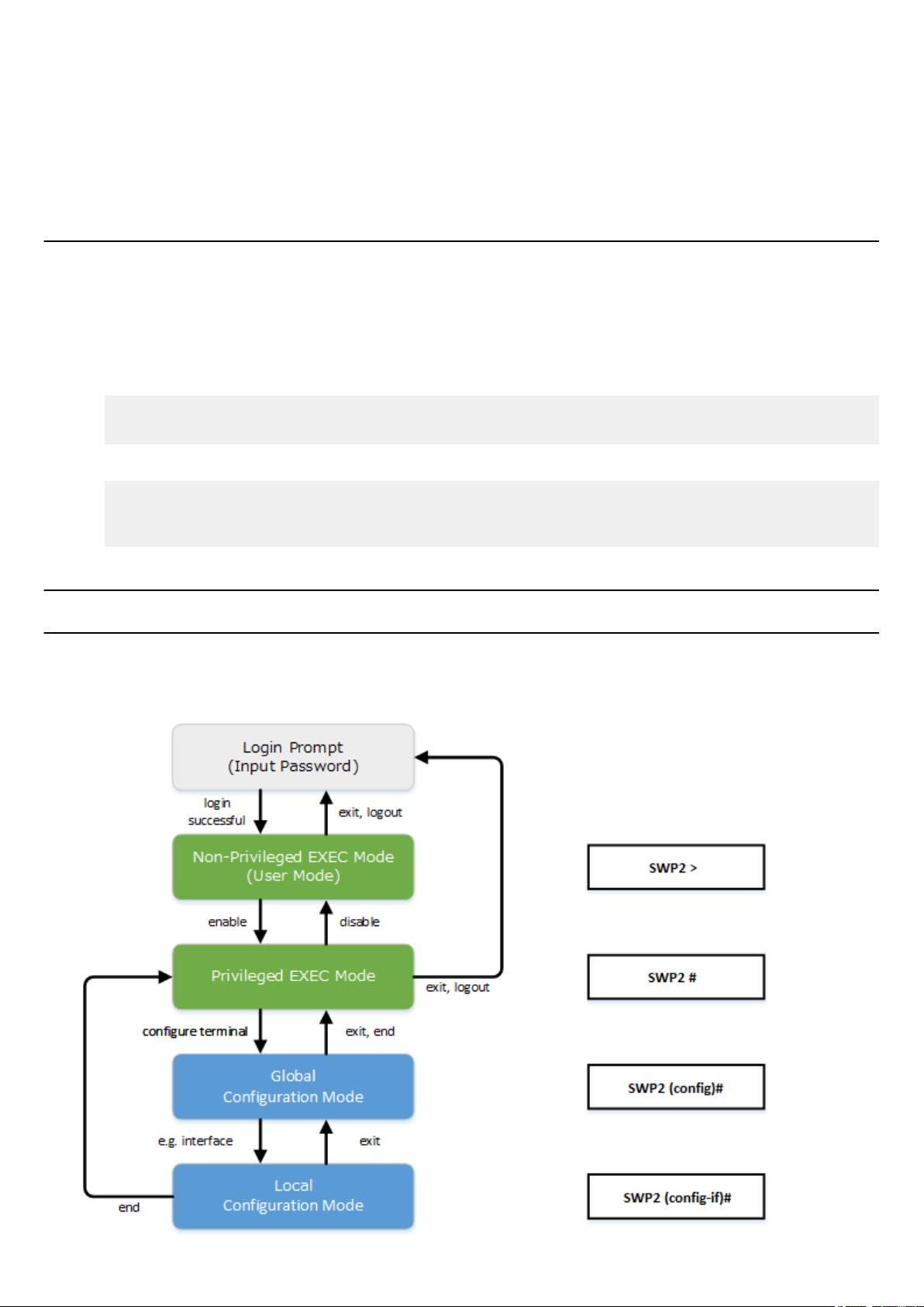
Command Reference | How to use the commands | 17
• If you PUT (write) with "config" specified as the remote path, the changes are added or overwritten to the current operating
settings. Settings that you do not add or change will remain as the current operating settings. Since the setting values are not
saved, you must use the write command etc. if you want to save them.
• If you want to start operation in USER mode with a completely new config file, specify "reconfig" as the remote path. After
updating startup-config, the unit restarts automatically, and begins operating with the new settings.
The encrypted password (password 8 or enable password 8 command format) is not applied to the settings even if it is
•
PUT to running-config via TFTP. And, users are not actually registered when making settings for users that include
encrypted passwords (username command).
2.3 Login
When the SWP2 has finished starting up, a login screen is displayed.
If a user is configured, enter the user name and password. If a user is not configured, omit the user name by pressing the Enter
key, and enter the login password instead to log in as an unknown user.
When authentication is successful, the command prompt appears. Since no user password is specified with the default settings,
you will be able to log in without a password.
• Login screen
Username:
Password:
• Console screen following login
SWP2 Rev.2.03.01 (Fri Sep 7 00:00:00 2018)
Copyright (c) 2018 Yamaha Corporation. All Rights Reserved.
SWP2>
2.4 Command input mode
2.4.1 Command input mode basics
In order to change the settings of the SWP2 or to reference the status, you must move to the appropriate command input mode
and then execute the command. Command input mode is divided into hierarchical levels as shown below, and the commands
that can be entered in each mode are different. By noting the prompt, the user can see which mode they are currently in.
Page 18

18 | Command Reference | How to use the commands
The basic commands related to moving between command input modes are described below. For commands that move from
global configuration mode mode to individual configuration mode, refer to "individual configuration mode."
• exit command
• logout command
• enable command
• disable command
• configure terminal command
• end command
2.4.2 individual configuration mode
individual configuration mode is the overall name for the mode in which you can make detailed settings for specific items such
as LAN/SFP+ port, VLAN interface, and QoS. To enter individual configuration mode, issue the command for transitioning to
the respective mode from global configuration mode.
On SWP2, individual configuration mode contains the following modes. Some of the modes within individual configuration
mode have a hierarchy. For example, policy map mode → policy map class mode.
individual configuration mode Transition command Prompt
interface mode interface command SWP2(config-if)#
line mode line con command
line vty command
VLAN mode vlan database command SWP2(config-vlan)#
VLAN access map mode vlan access-map command SWP2(config-vlan-access-map)#
MST mode
class map mode class-map command SWP2(config-cmap)#
policy map mode policy-map command SWP2(config-pmap)#
policy map class mode class command SWP2(config-pmap-c)#
LLDP agent mode lldp-agent command SWP2(lldp-agent)#
spanning-tree mst configuration
command
SWP2(config-line)#
SWP2(config-mst)#
2.4.3 Command prompt prefix
he command prompt prefix indicates the host name. In the default state, the host name is the model name "SWP2". This
indication can be changed by using the hostname command to specify the host name. In cases where multiple SWP2 units are
used, management will be easier if separate names are assigned to each switch.
Changing the host name
SWP2(config)# hostname Switch-012
Switch-012(config)#
2.4.4 Executing commands of a different input mode
Because the commands that can be used on the SWP2 differ depending on the mode, you must transition to the mode in which a
command can be executed before you execute that command. The do command is provided as a way to avoid this requirement.
By using the do command you can execute priviledged EXEC mode commands from any configuration mode. This allows you
to reference the current configuration or save settings from any configuration mode without having to transition to priviledged
EXEC mode.
However, since the completion function cannot be used with do, you must enter the command that follows either in its full
spelling or in its abbreviated form.
Entry in full spelling
•
SWP2(config)#do show running-config
• Entry in abbreviated form
SWP2(config)#do sh ru
2.5 Keyboard operations when using the console
Page 19

2.5.1 Basic operations for console input
The SWP2 allows the following operations in the command line.
• Moving the cursor
Keyboard operation Description and notes
→ Move right one character
← Move left one character
Command Reference | How to use the commands | 19
Press Esc, then F
Press Esc, then B
• Deleting an input character
Keyboard operation Description and notes
Press Esc, then D
• Other
Move right one word (move to the character following the
end of the word at the cursor location)
Move left one word (move to the first character of the word
at the cursor location)
Ctrl + A Move to the beginning of the line
Ctrl + E Move to the end of the line
Backspace
Ctrl + H
Ctrl + D
Ctrl + K Delete from the cursor position until the end of the line
Ctrl + U Delete all characters that are being entered
Delete the character at the left of the cursor
Delete the character at the cursor.
If this operation is performed when the command line is
empty, the result is the same as the exit command.
Delete from the cursor position until immediately before the
first space
Keyboard operation Description and notes
Exchange the character at the cursor position with the
Ctrl + T
Ctrl + C
Ctrl + Z
preceding character.
If the cursor is at the end of the line, exchange the preceding
character with the character that precedes it.
In unprivileged EXEC mode and priviledged EXEC mode,
discard the command being entered and move to the next
line.
In individual configuration mode, discard the command line
being entered and move to priviledged EXEC mode.
Command processing that is currently being executed will
be stopped. (ex: ping command)
Move from individual configuration mode to priviledged
EXEC mode.
This is the same operation as the end command.
2.5.2 Command help
By entering '?' in the command line you can search for the available commands or parameters.
SWP2#show vlan ?
<1-4094> VLAN id
access-map Show VLAN Access Map
brief VLAN information for all bridges (static and dynamic)
filter Show VLAN Access Map Filter
private-vlan private-vlan information
SWP2#show vlan
Page 20

20 | Command Reference | How to use the commands
2.5.3 Input command completion and keyword candidate list display
If you press the "Tab" key while entering a command in the console, the command name is completed. If you press the "Tab"
key after entering a keyword, a list of keyword candidates that can be entered next is shown. The same operation can also be
performed by pressing the "Ctrl + I" key.
• Command name completion
SWP2#con "press the <Tab>key"
↓
SWP2#configure
• Keyword candidate list display
SWP2(config)#vlan "press the <Tab> key"
access-map database filter
SWP2(config)#vlan
2.5.4 Entering command abbreviations
When you enter commands or parameters in abbreviated form, and the characters you entered can be recognized
unambiguously as a command or parameter, that command is executed.
Example of entering a command abbreviation (show running-config)
SWP2# sh run
2.5.5 Command history
By using the command history function, you can easily re-execute a command that you previously input, or partially modify a
previously input command and re-execute it. Command history is shown as a history that is common to all modes.
Operation is shown below.
Keyboard operation Description and notes
↑
Ctrl + P
↓
Ctrl + N
Move backward through command history
Move forward through command history
2.6 Commands that start with the word "show"
2.6.1 Modifiers
Modifiers send the information produced by the show command through a filter, restricting the content that is shown in the
screen and making it easier for you to see the desired information.
The SWP2 provides the following three modifiers for the show command.
Modifiers Description
include
grep
Output only the lines that include the specified character
string
exclude
Modifiers can be used only one at a time. You cannot specify more than one modifier.
• (Example) Using
SWP2#show running-config | grep vlan1
interface vlan1
http-server interface vlan1
telnet-server interface vlan1
• (Example) Using
SWP2# show spanning-tree | include Role
% po1: Port Number 505 - Ifindex 4601 - Port Id 0x81f9 - Role Disabled - State
Discarding
% port1.1: Port Number 905 - Ifindex 5001 - Port Id 0x8389 - Role Disabled -
show running-config to view information that includes VLAN #1 (vlan1).
show spanning-tree to view information that includes Role.
Output only the lines that do not include the specified
character string
Page 21

Command Reference | How to use the commands | 21
State Forwarding
% port1.2: Port Number 906 - Ifindex 5002 - Port Id 0x838a - Role Disabled State Forwarding
% port1.3: Port Number 907 - Ifindex 5003 - Port Id 0x838b - Role Disabled State Forwarding
% port1.4: Port Number 908 - Ifindex 5004 - Port Id 0x838c - Role Disabled State Forwarding
% port1.6: Port Number 910 - Ifindex 5006 - Port Id 0x838e - Role Disabled State Forwarding
% port1.7: Port Number 911 - Ifindex 5007 - Port Id 0x838f - Role Disabled State Forwarding
% port1.8: Port Number 912 - Ifindex 5008 - Port Id 0x8390 - Role Disabled State Forwarding
% port1.9: Port Number 913 - Ifindex 5009 - Port Id 0x8391 - Role Disabled State Forwarding
% port1.10: Port Number 914 - Ifindex 5010 - Port Id 0x8392 - Role Disabled State Forwarding
Page 22

22 | Command Reference | Configuration
Chapter 3
Configuration
3.1 Manage setting values
The SWP2 uses the following configurations to manage its settings.
Types of configuration Description
Running configuration (running-config)
Startup configuration (startup-config)
Backup configuration (backup-config)
Default configuration (default-config)
The start-up flow for the SWP2 system is as follows.
1. Reference DIP switch #1 and determine the CONFIG mode
• If DIP switch #1 is up (OFF), start up in DANTE mode
If DIP switch #1 is down (ON), start up in USER mode
•
2. Determine the startup configuration for each CONFIG mode
• For DANTE mode
• Use the default configuration that was selected according to the settings of DIP switches #2/#3
• For USER mode
• If a startup configuration for USER mode exists, use the corresponding data
• If a startup configuration for USER mode does not exist, use the default configuration that was selected according to
the settings of DIP switches #2/#3.
3. Load the startup configuration into RAM as the running configuration
• If a backup configuration exists in DANTE mode, overwrite the corresponding data onto the running configuration
If commands etc. are used to modify the settings while the SWP2 is running, the modified settings are immediately reflected in
the running configuration. After modifying the running configuration, executing the write or copy command in USER mode
will update the startup configuration. In DANTE mode, executing the backup-config command will update the backup
configuration. If you restart without saving the content that was specified or modified, the settings or modifications are lost.
Please be aware of this.
Setting values currently used for
operation. Managed in RAM.
In USER mode, setting values saved in
Flash ROM.
In DANTE mode, the same setting
values as the default configuration.
Setting values for some functions saved
in DANTE mode. Managed in Flash
ROM.
Default setting values. Managed in Flash
ROM.
Created based on the VLAN preset that
is selected by the settings of DIP
switches #2/#3 at start-up.
User operations that can be
performed
Note
Save to startup configuration (in USER
mode)
Save some functions to backup
configuration (in DANTE mode)
Note
Update by running configuration (in
USER mode)
Update by running configuration (in
DANTE mode)
No operations possible
3.2 Default setting values
On the SWP2, the VLAN preset specified by DIP switches #2/#3 will be the default setting values. The VLAN preset types for
DIP switch #2/#3 settings are as follows.
• DIP switch #2/#3 settings
Setting position
#2 #3
Up (OFF) Up (OFF)
VLAN preset type
Normal
Page 23

Command Reference | Configuration | 23
Setting position
#2 #3
Down (ON) Up (OFF)
Up (OFF) Down (ON) B
Down (ON) Down (ON) C
The common setting values and presets are shown first, and then the specific to the presets setting values are shown.
• Settings common to all presets (system-wide)
Category Setting item Default value
Console timeout 600 sec
Terminal settings
Password
Time management
Number of VTYs 8
Number of lines displayed 24
Login password of no user none
Administrator password none
Password encryption not encrypted
Time zone UTC (±0)
NTP server none
VLAN preset type
A
NTP update cycle once per hour
RMON Behavior enabled
firmware-update url http://
Download URL
Firmware update
Allow revision-down don't allow
Timeout 300 sec
Behavior disabled
LLDP
Automatically set function disabled
Behavior enabled (can not change)
L2MS
Role slave (can not change)
Debug level log output OFF
Information level log output ON
SYSLOG
Error level log output ON
SYSLOG server none
Telnet server status run
Telnet server access allow only VLAN #1
www.rtpro.yamaha.co.jp/firmware/
revision-up/swp2.bin
SSH server status do not run
Access control
Maintenance VLAN VLAN interface VLAN #1
L2 switching
TFTP server status do not run
HTTP server status run
HTTP server access allow only VLAN #1
Secure HTTP server status do not run
Automatic MAC address learning enabled
Automatic MAC address learning
aging time
300 sec
Page 24

24 | Command Reference | Configuration
Category Setting item Default value
DNS cliant Behavior enabled
Spanning tree enabled
Proprietary loop detection enabled
QoS enabled
Traffic control
Web GUI Language setting English
• Settings common to all models and presets (LAN/SFP+ port)
Category Setting item Default value
Common setting
L2MS L2MS filter depends on preset
L2 switching
QoS DSCP - transmission queue ID
conversion table
Flow control (IEEE 802.3x) disabled
Speed/duplex mode setting auto
Cross/straight automatic detection enabled
MRU 1,522 Byte
Port description none
EEE disabled
Port Mode depends on preset
Associated VLAN ID depends on preset
Spanning tree depends on preset
Proprietary loop detection enabled
DSCP: 8 → transmission queue: 2
Other than above → transmission
queue: 0
QoS trust mode DSCP
Traffic control
• Default settings for the Normal VLAN preset of the SWP2 (entire system)
Category Setting item Default setting values
IP multicast control
• SWP2's VLAN preset Normal settings (LAN/SFP+ port)
Interface L2MS Filter LAG(Static) Port Mode VLAN STP
port1.1 Disable - Access 1(default) -
port1.2 Disable - Access 1(default) -
port1.3 Disable - Access 1(default) -
port1.4 Disable - Access 1(default) -
port1.5 Disable - Access 1(default) -
port1.6 Disable - Access 1(default) -
port1.7 Disable - Access 1(default) -
Flow control (IEEE 802.3x) disabled
Storm control disabled
Function to transmit IGMP/MLD query
when topology changes
Enabled (wait time 5 sec)
port1.8 Disable - Access 1(default) -
port1.9 Disable - Access 1(default) -
port1.10 Disable - Access 1(default) -
port1.11 Disable - Access 1(default) ✓
Page 25

Command Reference | Configuration | 25
Interface L2MS Filter LAG(Static) Port Mode VLAN STP
port1.12 Disable - Access 1(default) ✓
• SWP2's VLAN preset Normal settings (VLAN interface)
• VLAN #1(for Dante and Control)
IPv4 Address: DHCP
•
• IGMP Snooping: Enable
• Querier : Enable
• Query Interval : 30 sec
• Fast-Leave : Disable
• Check TTL : Disable
• Default settings for the Normal VLAN preset A of the SWP2 (entire system)
Category Setting item Default setting values
IP multicast control
• SWP2's VLAN preset A settings (LAN/SFP+ port)
Interface L2MS Filter LAG(static) Port Mode VLAN STP
port1.1 Disable - Access 1(default) -
port1.2 Disable - Access 1(default) -
port1.3 Disable - Access 1(default) -
port1.4 Disable - Access 1(default) -
port1.5 Disable - Access 2 -
port1.6 Disable - Access 2 -
port1.7 Disable - Access 1(default) -
port1.8 Disable - Access 1(default) -
port1.9 Disable - Access 2 -
port1.10 Disable - Access 2 -
port1.11 Disable
port1.12 Disable
Function to transmit IGMP/MLD query
when topology changes
sa1 Trunk 1(native), 2 ✓
Enabled (wait time 5 sec)
• SWP2's VLAN preset A settings (VLAN interface)
• VLAN #1(for Dante)
IPv4 Address: DHCP
•
• IGMP Snooping: Enable
• Querier : Enable
• Query Interval : 30 sec
• Fast-Leave : Disable
• Check TTL : Disable
• VLAN #2(for Control)
• IGMP Snooping: Disable
• Default settings for the Normal VLAN preset B of the SWP2 (entire system)
Category Setting item Default setting values
IP multicast control
• SWP2's VLAN preset B settings (LAN/SFP+ port)
Interface L2MS Filter LAG(static) Port Mode VLAN STP
port1.1 Disable - Access 1(default) -
port1.2 Disable - Access 1(default) -
Function to transmit IGMP/MLD query
when topology changes
Enabled (wait time 5 sec)
Page 26

26 | Command Reference | Configuration
Interface L2MS Filter LAG(static) Port Mode VLAN STP
port1.3 Disable - Access 1(default) -
port1.4 Disable - Access 1(default) -
port1.5 Disable - Access 2 -
port1.6 Disable - Access 2 -
port1.7 Disable - Access 1(default) -
port1.8 Disable - Access 2 -
port1.9 Disable
port1.10 Disable
port1.11 Disable
port1.12 Disable
• SWP2's VLAN preset B settings (VLAN interface)
• VLAN #1(for Dante)
IPv4 Address: DHCP
•
• IGMP Snooping: Enable
• Querier : Enable
• Query Interval : 30 sec
• Fast-leave : Disable
• Check TTL : Disable
• VLAN #2(for Control)
• IGMP Snooping: Disable
• SWP2's VLAN preset C settings (LAN/SFP+ port)
Interface L2MS Filter LAG(static) Port Mode VLAN STP
port1.1 Disable - Access 1(default) -
port1.2 Disable - Access 1(default) -
port1.3 Disable - Access 1(default) -
sa1 Trunk 1(native), 2 ✓
sa2 Trunk 1(native), 2 ✓
port1.4 Enable - Access 2 -
port1.5 Enable - Access 2 -
port1.6 Enable - Access 2 -
port1.7 Disable - Access 1(default) -
port1.8 Disable - Access 1(default) -
port1.9 Enable - Access 2 -
port1.10 Enable - Access 2 -
port1.11 Disable - Access 1(default) -
port1.12 Enable - Access 2 -
• SWP2's VLAN preset C settings (VLAN interface)
• VLAN #1(for Dante)
• IPv4 Address: DHCP
• IGMP Snooping: Enable
• Querier : Enable
• Query Interval : 30 sec
• Fast-leave : Disable
• Check TTL : Disable
• VLAN #2(for Control)
• IGMP Snooping: Enable
• Querier : Enable
• Query Interval : 30 sec
• Fast-leave : Disable
Page 27

• Check TTL : Disable
Command Reference | Configuration | 27
Page 28

28 | Command Reference |
Maintenance and operation functions
Chapter 4
Maintenance and operation functions
4.1 Passwords
4.1.1 Set password for unnamed user
[Syntax]
password password
no password
[Parameter]
password : Login password for unnamed user
Single-byte alphanumeric characters, and symbols other than the single-byte characters '|', '>', and '?'
(32 characters or less)
The first character must be a single-byte alphanumeric character
[Initial value]
no password
[Input mode]
global configuration mode
[Description]
Sets the password for logging in as an unnamed user.
If this command is executed with the "no" syntax, the unnamed user password for logging is deleted.
[Note]
If the password was encrypted by the password-encryption command, it is shown in the configuration in the form "password
8 password."
The user cannot enter the password in this form when making configuration settings from the command line.
[Example]
Specify user1234 as the unnamed user password.
SWP2(config)#password user1234
Delete the unnamed user password.
SWP2(config)#no password
4.1.2 Set administrator password
[Syntax]
enable password password
no enable password
[Parameter]
password : Administrator password
Single-byte alphanumeric characters, and symbols other than the single-byte characters '|', '>', and '?'
(32 characters or less)
The first character must be a single-byte alphanumeric character
[Initial value]
no enable password
[Input mode]
global configuration mode
Page 29

Command Reference | Maintenance and operation functions | 29
[Description]
Specifies the administrator password needed to enter priviledged EXEC mode.
If this command is executed with the "no" syntax, the administrator password is deleted.
[Note]
If the password was encrypted by the password-encryption command, it is shown in the configuration in the form "enable
password 8 password."
The user cannot enter the password in this form when making configuration settings from the command line.
[Example]
Specify admin1234 as the administrator password.
SWP2(config)#enable password admin1234
Delete the administrator password.
SWP2(config)#no enable password
4.1.3 Encrypt password
[Syntax]
password-encryption switch
no password-encryption
[Parameter]
switch : Set password encryption
Setting value Description
enable Encrypt
disable Don't encrypt
[Initial value]
password-encryption disable
[Input mode]
global configuration mode
[Description]
Enables password encryption.
If this is enabled, the password entered by the password command, the enable paassword command, and the username
command are saved in the configuration in an encrypted form.
If this command is executed with the "no" syntax, password encryption is disabled, and the password entered by the password
command, the enable paassword command, and the username command are saved in the configuration as plaintext.
[Note]
If password encryption is changed from disabled to enabled, previously-entered passwords are converted from plaintext to an
encrypted form; however if it is changed from enabled to disabled, previously-encrypted passwords in a configuration file do
not return to plaintext.
[Example]
Enables password encryption.
SWP2(config)#password-encryption enable
Disabled password encryption.
SWP2(config)#no password-encryption
4.1.4 Allow login with special password
[Syntax]
force-password switch
no force-password
Page 30

30 | Command Reference | Maintenance and operation functions
[Parameter]
switch : Allow login by special password
Setting value Description
enable Allow
disable Don't allow
[Initial value]
force-password enable
[Input mode]
global configuration mode
[Description]
Enable login with special password.
If this is enabled, only when logging in from a serial console, it is possible to log in using "w,lXlma" (lowercase W, comma,
lowercase L, uppercase X, and lowercase L, M, and A) instead of the specified user password.
If you login with the special password, you will be in priviledged EXEC mode.
If this command is executed with the "no" syntax, login with the special password is disabled.
[Example]
Enable login with special password.
SWP2(config)#force-password enable
Disable login with special password.
SWP2(config)#no force-password
4.2 User account maintenance
4.2.1 Set user password
[Syntax]
username username [privilege privilege] [password password]
no username username
[Keyword]
privilege : Specifies the user's privileges
password : Specifies the user's password
[Parameter]
username : User name
Single-byte alphanumeric characters (32 characters or less)
privilege : Whether to grant privilege
Setting value Description
on
off
password : User's login password
Password input is not requested when moving to
privileged EXEC mode
Access to Web GUI is allowed with
administrator privileges
Password input is requested when moving to
privileged EXEC mode
Access to Web GUI is allowed with guest
Page 31

Command Reference | Maintenance and operation functions | 31
Single-type alphanumeric characters and " and ' and | and ? and single-byte symbols other than space
characters (32characters or less)
The first character must be a single-byte alphanumeric character
[Initial value]
none
[Input mode]
global configuration mode
[Description]
Sets user information.
A maximum of 32 items of user information can be registered.
The following words cannot be registered as user names.
lp, adm, bin, ftp, gdm, man, rpc, sys, xfs, halt, mail, news, nscd, sync, uucp, root, games, daemon, gopher, nobody, ftpuser,
mtsuser, rpcuser, mailnull, operator, shutdown
[Note]
If the password was encrypted by the password-encryption command, it is shown in the configuration in the form "username
username 8 password password."
The user cannot enter the password in this form when making configuration settings from the command line.
[Example]
Set the user "user1234".
SWP2(config)#username user1234
Grant privileges to user user1234 and specify a password.
SWP2(config)#username user1234 privilege on password user_pass
4.2.2 Show login user information
[Syntax]
show users
[Input mode]
unprivileged EXEC mode, priviledged EXEC mode, global configuration mode
[Description]
Shows information on the current logged-in users.
The following items are shown.
Item Description
Shows the login method.
Line
con 0 is the serial console port
vty N is the VTY port
http N is the Web GUI
Own An * is shown for the line of one's own connection port.
User Shows the currently logged-in user names.
Status
Login time Shows the login time.
IP address Shows the IP address of the connected user.
[Example]
Show login information for the users.
SWP2>show users
Shows the login status. If the user is in use, this indicates
Login.
Page 32

32 | Command Reference |
Line Own User Status Login time IP address
-------------------------------------------------------------------------------------
-------- con 0 user1234 Login 02:15:23
vty 0 * operators1 Login 00:12:59 192.168.100.1
vty 1 abcdefghijklmnopqrstuvwxyzabcdef Login 00:00:50 192.168.100.24
vty 2 - Login 00:00:21 192.168.100.10
vty 3 - - vty 4 - - vty 5 - - vty 6 - - vty 7 - - http 0 user1234 Login 01:12:25 192.168.100.4
http 1 (noname) Login 00:18:04 192.168.100.102
http 2 - - http 3 - - -
4.2.3 Set banner
[Syntax]
banner motd word
no banner motd
[Parameter]
Maintenance and operation functions
word : Single-byte alphanumeric characters and single-byte symbols ( 256 characters or less)
[Initial value]
no banner motd
[Input mode]
global configuration mode
[Description]
Sets the banner that is displayed when logging in to the console.
[Example]
Set the banner display to "Hello World!".
Username:
Password:
SWP2 Rev.2.03.01 (Fri Sep 7 00:00:00 2018)
Copyright (c) 2018 Yamaha Corporation. All Rights Reserved.
SWP2>enable
SWP2#configure terminal
Enter configuration commands, one per line. End with CNTL/Z.
SWP2(config)#banner motd Hello World!
SWP2(config)#exit
SWP2#exit
Username:
Password:
Hello World!
SWP2>enable
SWP2#configure terminal
Enter configuration commands, one per line. End with CNTL/Z.
SWP2(config)#no banner motd
SWP2(config)#exit
SWP2#exit
Username:
Password:
SWP2 Rev.2.03.01 (Fri Sep 7 00:00:00 2018)
Copyright (c) 2018 Yamaha Corporation. All Rights Reserved.
Page 33

Command Reference | Maintenance and operation functions | 33
SWP2>
4.3 Configuration management
4.3.1 Save running configuration
[Syntax]
copy running-config startup-config
[Input mode]
priviledged EXEC mode
[Description]
Saves the current operating settings (running configuration) as the settings for startup (startup configuration).
[Note]
The save-destination startup configuration is determined by the unit's DIP switch #1 at the time that the unit is started.
The running configuration can also be saved by executing the write command.
This command can be used to save settings only when in USER mode. When in DANTE mode, the backup-config command
can be used to save some of the settings.
[Example]
Save the running configuration.
SWP2#copy running-config startup-config
Succeeded to write configuration
SWP2#
4.3.2 Save running configuration
[Syntax]
write
[Input mode]
priviledged EXEC mode, individual configuration mode
[Description]
Saves the current operating settings (running configuration) as the settings for startup (startup configuration).
[Note]
The save-destination startup configuration is determined by the unit's DIP switch #1 at the time that the unit is started.
The running configuration can also be saved by executing the copy running-config startup-config command.
This command can be used to save settings only when in USER mode. When in DANTE mode, the backup-config command
can be used to save some of the settings.
[Example]
Save the running configuration.
SWP2#write
Succeeded to write configuration.
SWP2#
4.3.3 Save certain functions to the backup configuration
[Syntax]
backup-config
[Input mode]
priviledged EXEC mode
[Description]
Backup the settings of certain functions.
This applies to the following functions.
• Settings related to IPv4 addresses
Settings related to time zone
•
• Settings related to user account
Page 34

34 | Command Reference | Maintenance and operation functions
• Settings related to firmware updating
• Settings related to SYSLOG
Settings related to HTTP server functions
•
• Settings related to Telnet server functions
• Settings related to SSH server functions
• Settings related to TFTP server functions
Saves the settings of certain functions to the backup configuration.
If a backup configuration exists when the SWP2 starts in DANTE mode, those settings are restored to the running
configuration.
[Note]
This command can be used only when the configuration mode of the SWP2 is DANTE mode.
[Example]
Save the settings of the applicable functions to the backup configuration.
SWP2#backup-config
Succeeded to write backup configuration
SWP2#
4.3.4 Show the running configuration
[Syntax]
show running-config [section]
[Parameter]
section : Section to be shown
access-list Access list related
http-server HTTP server related
interface Interface related
ip IP related
ipv6 IPv6 related
key Authentication key related
l2ms L2MS related
lldp LLDP related
snmp SNMP related
spanning-tree STP related
ssh-server SSH server related
switch Switch setting related
telnet-sever TELNET server related
Setting value Description
[Input mode]
priviledged EXEC mode, individual configuration mode
[Description]
Shows the currently-operating settings (running configuration).
If section is not specified, all settings are shown.
[Example]
Show the running configuration.
SWP2#show running-config
!
interface port1.1
switchport
Page 35

Command Reference | Maintenance and operation functions | 35
...
!
line con 0
line vty 0 7
!
end
SWP2#
4.3.5 Show startup configuration
[Syntax]
show startup-config
[Input mode]
priviledged EXEC mode
[Description]
Shows the startup settings (startup configuration).
[Note]
The startup configuration that is shown is determined by the unit's DIP switch #1 at the time that the unit is started.
[Example]
Shows the startup settings (startup configuration) at next startup.
SWP2#show startup-config
!
! Last Modified: Mon Jan 01 00:00:00 UTC 2018
!
qos enable
qos dscp-queue 0 0
qos dscp-queue 1 0
qos dscp-queue 2 0
qos dscp-queue 3 0
qos dscp-queue 4 0
...
!
telnet-server enable
!
line con 0
line vty 0 7
!
end
SWP2#
4.3.6 Show backup configuration
[Syntax]
show backup-config
[Input mode]
priviledged EXEC mode
[Description]
Shows the backup settings (backup configuration).
[Note]
Executing this command while operating in USER mode results in an error.
[Example]
Show the backup configuration.
SWP2#show backup-config
!
! Last backup: Fri Sep 7 00:00:00 UTC 2018
!
interface vlan1
ip address dhcp
Page 36

36 | Command Reference |
!
interface vlan2
!
http-server enable
http-server language english
!
telnet-server enable
!
end
SWP2#
Maintenance and operation functions
4.3.7 Erase startup configuration
[Syntax]
erase startup-config
[Input mode]
priviledged EXEC mode
[Description]
Erase the settings used at startup (startup config) and the information associated with them.
[Note]
The startup configuration that is erased is determined by the unit's DIP switch #1 at the time that the unit is started.
[Example]
Erase the startup configuration.
SWP2#erase startup-config
Succeeded to erase configuration.
SWP2#
4.3.8 Erase backup of certain functions
[Syntax]
erase backup-config
[Input mode]
priviledged EXEC mode
[Description]
Erase the settings of certain functions (backup config) and the information associated with them.
[Note]
Executing this command while operating in USER mode results in an error.
[Example]
Erase the backup configuration.
SWP2#erase backup-config
Succeeded to erase configuration.
SWP2#
4.4 Manage boot information
4.4.1 Show boot information
[Syntax]
show boot num
show boot all
show boot list
[Keyword]
all : Shows up to five entries of the boot information history
list : Shows a simplified version of up to five entries of the boot information history
Page 37

Command Reference | Maintenance and operation functions | 37
[Parameter]
num : <0-4>
Shows the boot history entry of the specified number
[Input mode]
unprivileged EXEC mode, priviledged EXEC mode
[Description]
Show the boot information.
[Note]
This history is cleared when you execute the cold start command or the clear boot list command.
[Example]
Show the current boot information.
SWP2>show boot
Running EXEC: SWP2 Rev.2.03.01 (Fri Sep 7 00:00:00 2018)
Previous EXEC: SWP2 Rev.2.03.01 (Fri Sep 7 00:00:00 2018)
Restart by reload command
Shows a list of the boot history.
SWP2>show boot list
No. Date Time Info
--- ---------- -------- -------------------------------------------------
0 2018/03/15 09:50:29 Restart by reload command
1 2018/03/14 20:24:40 Power-on boot
--- ---------- -------- -------------------------------------------------
4.4.2 Clear boot information
[Syntax]
clear boot list
[Input mode]
priviledged EXEC mode
[Description]
Clears the boot information history.
[Example]
Clear the boot information.
SWP2#clear boot list
4.5 Show unit information
4.5.1 Show inventory information
[Syntax]
show inventory
[Input mode]
unprivileged EXEC mode, priviledged EXEC mode
[Description]
Shows inventory information for this unit and the SFP+ modules.
The following items are shown.
Item Description
NAME Name
DESCR Description
Vendor Vendor name
PID Product ID
Page 38

38 | Command Reference | Maintenance and operation functions
Item Description
VID Version ID, 0 if invalid
SN Serial number
[Example]
Show inventory information.
SWP2>show inventory
NAME : L2 switch
DESCR : SWP2
Vendor: Yamaha
PID : SWP2
VID : 0000
SN : SMF00000
NAME : SFP1
DESCR : 10G Base-LR
Vendor: Yamaha
PID : YSFP-10G-LR
VID : V1.0
SN : Z5H00000YJ
NAME : SFP2
DESCR : 10G Base-LR
Vendor: Yamaha
PID : YSFP-10G-LR
VID : V1.0
SN : Z5H00001YJ
SWP2>
4.5.2 Show operating information
[Syntax]
show environment
[Input mode]
unprivileged EXEC mode, priviledged EXEC mode
[Description]
Shows information about the system's operating environment.
The following items are shown.
• Boot version
•
Firmware revision
• Serial number
• MAC address
• CPU usage ratio
• Memory usage ratio
• Firmware file
• CONFIG mode
• VLAN preset (only in DANTE mode)
• Serial baud rate
• Boot time
• Current time
• Elapsed time from boot
[Example]
Show operating information.
SWP2>show environment
SWP2 BootROM Ver.1.01
SWP2 Rev.2.03.01 (Fri Sep 7 00:00:00 2018)
main=SWP2 ver=00 serial=S00000000 MAC-Address=ac44.f200.0000
CPU: 4%(5sec) 5%(1min) 5%(5min) Memory: 25% used
Startup firmware: exec0
Page 39

Configration mode: DANTE
VLAN preset: Normal
Serial Baudrate: 9600
Boot time: 2018/10/01 06:14:46 +00:00
Current time: 2018/10/01 06:49:23 +00:00
Elapsed time from boot: 0days 00:34:41
SWP2>
4.5.3 Show currently-executing processes
[Syntax]
show process
[Input mode]
priviledged EXEC mode
[Description]
Shows all currently-executing processes.
[Example]
Show currently-executing processes.
SWP2#show process
Command Reference | Maintenance and operation functions | 39
4.5.4 Show technical support information
[Syntax]
show tech-support
[Input mode]
priviledged EXEC mode
[Description]
Shows a list of the results of executing the following commands useful for technical support.
• show running-config
show startup-config
•
• show environment
• show dipsw
• show inventory
• show boot all
• show logging
• show process
• show users
• show interface
• show frame-counter
• show vlan brief
• show spanning-tree mst detail
• show etherchannel status detail
• show loop-detect
• show mac-address-table
• show l2ms detail
• show qos queue-counters
• show ddm status
• show errdisable
• show auth status
• show auth supplicant
• show error port-led
• show ip interface brief
• show ipv6 interface brief
• show ip route
• show ip route database
• show ipv6 route
• show ipv6 route database
Page 40

40 | Command Reference | Maintenance and operation functions
• show arp
• show ipv6 neighbors
show ip igmp snooping groups
•
• show ip igmp snooping interface
[Example]
Show technical support information.
SWP2#show tech-support
#
# Information for Yamaha Technical Support
#
*** show running-config ***
!
qos enable
qos dscp-queue 0 0
...
#
# End of Information for Yamaha Technical Support
#
SWP2#
4.6 Time management
4.6.1 Set clock manually
[Syntax]
clock set time month day year
[Parameter]
time : hh:mm:ss
Time
month : <1-12> or Jan, Feb, Mar, ... , Dec
Month or name of month
day : <1-31>
Day
year : Year (four digits)
[Input mode]
priviledged EXEC mode
[Description]
Set the system time.
[Example]
Set the time to 0 hours 0 minutes 0 seconds on January 1, 2015.
SWP2#clock set 00:00:00 Jan 1 2015
4.6.2 Set time zone
[Syntax]
clock timezone zone
clock timezone offset
no clock timezone
Page 41

[Parameter]
zone : UTC, JST
Name of the time zone shown when standard time is in effect
offset : -12:00, -11:00, ... , -1:00, +1:00, ... , +13:00
Enter the difference from UTC
[Initial value]
clock timezone UTC
[Input mode]
global configuration mode
[Description]
Sets the time zone.
If this command is executed with the "no" syntax, UTC is specified.
[Example]
Set the time zone to JST.
SWP2(config)#clock timezone JST
Set the time zone to UTC+9 hours.
Command Reference | Maintenance and operation functions | 41
SWP2(config)#clock timezone +9:00
4.6.3 Show current time
[Syntax]
show clock
[Input mode]
unprivileged EXEC mode, priviledged EXEC mode
[Description]
Shows the current time, year, month, and date.
[Example]
Show current time.
SWP2>show clock
Thu Jan 1 00:00:00 JST 2015
4.6.4 Set NTP server
[Syntax]
ntpdate server ipv4 ipv4_addr
ntpdate server ipv6 ipv6_addr
ntpdate server name fqdn
no ntpdate server
[Keyword]
ipv4 : Specify the NTP server by IPv4 address
ipv6 : Specify the NTP server by IPv6 address
name : Specify the NTP server by host name
[Parameter]
ipv4_addr : IPv4 address of the NTP server
ipv6_addr : IPv6 address of the NTP server
If you specify an IPv6 link local address, you must also specify the output interface (fe80::X%vlanN
format)
Page 42

42 | Command Reference | Maintenance and operation functions
fqdn : Host name of the NTP server
As character types, alphabetical characters (uppercase/lowercase), numerals, . (period), and - (hyphen)
can be used
[Initial value]
none
[Input mode]
global configuration mode
[Description]
Registers the address or host name of the NTP server.
Up to two instances of this command can be set.
If this command is executed with the "no" syntax, the NTP server setting is deleted.
If time synchronization is performed with two NTP servers specified, they are queried in the order of NTP server 1 and NTP
server 2 as shown by the show ntpdate command.
The query to NTP server 2 is performed only if synchronization with NTP server 1 fails.
[Example]
Specify 192.168.1.1 as the NTP server.
SWP2(config)#ntpdate server ipv4 192.168.1.1
Specify fe80::2a0:deff:fe11:2233%vlan1 as the NTP server.
SWP2(config)#ntpdate server ipv6 fe80::2a0:deff:fe11:2233%vlan1
Specify ntp.example.com as the NTP server.
SWP2(config)#ntpdate server name ntp.example.com
4.6.5 Synchronize time from NTP server (one-shot update)
[Syntax]
ntpdate oneshot
[Input mode]
priviledged EXEC mode
[Description]
Attempts to obtain time information from the registered NTP server.
This is performed only once when this command is executed.
[Example]
Obtain time information from the NTP server.
SWP2#ntpdate oneshot
4.6.6 Synchronize time from NTP server (update interval)
[Syntax]
ntpdate interval interval-time
no ntpdate interval
[Parameter]
interval-time : <0-24>
Interval (hours) for time synchronization. If this is set to 0 hours, periodic synchronization will not
occur.
[Initial value]
ntpdate interval 1
Page 43

Command Reference | Maintenance and operation functions | 43
[Input mode]
global configuration mode
[Description]
Specifies the interval (in one-hour units) at which time information is periodically obtained from the registered NTP server.
If this command is executed with the "no" syntax, the setting returns to the default.
When this command is executed, the time is updated immediately, and is subsequently updated at the specified interval.
[Example]
Request the time every two hours.
SWP2(config)#ntpdate interval 2
Disable periodic time synchronization.
SWP2(config)#ntpdate interval 0
4.6.7 Show NTP server time synchronization settings
[Syntax]
show ntpdate
[Input mode]
unprivileged EXEC mode, priviledged EXEC mode
[Description]
Shows the settings that are related to time synchronization from an NTP server.
[Example]
Show time synchronization settings. *If the synchronization update interval is one hour
SWP2#show ntpdate
NTP Server 1 : ntp.nict.jp
NTP Server 2 : none
adjust time : Thu Jan 1 09:00:00 2015 + interval 1 hour
sync server : ntp.nict.jp
Show time synchronization settings. *If periodic synchronization is not being performed
SWP2#show ntpdate
NTP Server 1 : ntp.nict.jp
NTP Server 2 : none
adjust time : Thu Jan 1 09:00:00 2015
sync server : ntp.nict.jp
4.7 Terminal settings
4.7.1 Move to line mode (console terminal)
[Syntax]
line con port
[Parameter]
port : 0
Serial console port number
[Initial value]
line con 0
[Input mode]
global configuration mode
[Description]
Moves to line mode in order to make console terminal settings.
Page 44

44 | Command Reference | Maintenance and operation functions
[Note]
To return from line mode to global configuration mode, use the exit command. To return to priviledged EXEC mode, use the
end command.
[Example]
Move to line mode in order to make console terminal settings.
SWP2(config)#line con 0
SWP2(config-line)#
4.7.2 Set VTY port and move to line mode (VTY port)
[Syntax]
line vty port1 [
no line vty port1 [port2]
[Parameter]
port1 : <0-7>
port2 : <0-7>
port2]
VTY port number
Last VTY port number when specifying a range
[Initial value]
no line vty 0 7
[Input mode]
global configuration mode
[Description]
After enabling the specified VTY ports, moves to line mode for making VTY port settings.
If this command is executed with the "no" syntax, the specified VTY ports are disabled.
If you specify port2, a range of ports is specified; all VTY ports from port1 through port2 are specified. port2 must be a number
greater than port1.
[Note]
The maximum number of simultaneous Telnet client connections depends on the number of VTY ports that are enabled.
To return from line mode to global configuration mode, use the exit command. To return to priviledged EXEC mode, use the
end command.
[Example]
Enable VTY port #0 and then move to line mode.
SWP2(config)#line vty 0
SWP2(config-line)#
4.7.3 Set terminal login timeout
[Syntax]
exec-timeout min [sec]
no exec-timeout
[Parameter]
min : <0-35791>
Timeout time (minutes)
sec : <0-2147483>
Timeout time (seconds)
[Initial value]
exec-timeout 10
[Input mode]
line mode
Page 45

Command Reference | Maintenance and operation functions | 45
[Description]
Sets the time after which automatic logout occurs if there has been no key input from the console terminal or VTY.
If sec is omitted, 0 is specified. If min and sec are both set to 0, automatic logout does not occur.
If this command is executed with the "no" syntax, the setting returns to the default.
[Note]
After this command is executed, the setting is applied starting at the next login.
[Example]
Set the console timeout time to five minutes.
SWP2(config)#line con 0
SWP2(config-line)#exec-timeout 5 0
SWP2(config-line)#
4.7.4 Change the number of lines displayed per page for the terminal in use
[Syntax]
terminal length line
terminal no length
[Parameter]
line : <0-512>
Number of lines displayed per page on the terminal
[Input mode]
unprivileged EXEC mode, priviledged EXEC mode
[Description]
Changes the number of lines displayed per page for the terminal in use.
If line is set to 0, the display is not paused per page.
If the terminal no length command is executed, the number of lines is set to 24 in the case of a serial console, or to the window
size when connected in the case of VTY.
[Note]
When this command is executed, the change applies immediately.
The result of executing this command takes priority over the setting applied by the service terminal-length command.
[Example]
Change the number of lines displayed per page for the terminal in use to 100 lines.
SWP2>terminal length 100
SWP2>
4.7.5 Set the number of lines displayed per page on the terminal
[Syntax]
service terminal-length line
no service terminal-length
[Parameter]
line : <0-512>
Number of lines displayed per page on the terminal
[Initial value]
no service terminal-length
[Input mode]
global configuration mode
[Description]
Sets the number of lines displayed per page on the terminal.
If line is set to 0, the display is not paused per page.
Page 46

46 | Command Reference | Maintenance and operation functions
If this command is executed with the "no" syntax, the number of lines is set to 24 in the case of a serial console, or to the
window size when connected in the case of VTY.
[Note]
After this command is executed, the setting is applied starting at the next login.
If the terminal length command is executed, the result of executing the terminal length command takes priority.
[Example]
Change the number of lines displayed per page for the terminal in use to 100 lines.
SWP2(config)#service terminal-length 100
SWP2(config)#
4.8 Management
4.8.1 Set management VLAN
[Syntax]
management interface interface
no management interface
[Parameter]
interface : VLAN interface name
[Initial value]
management interface vlan1
[Input mode]
global configuration mode
[Description]
Set the VLAN that is used for management.
By setting this command, it will be possible to set and acquire the IP address assigned by the L2MS master to the corresponding
VLAN when operating as an L2MS slave.
If this is executed with the "no" syntax, or if the VLAN is deleted, this command also returns to the default settings.
[Example]
Set VLAN #2 as the management VLAN.
SWP2(config)#management interface vlan2
4.9 SYSLOG
4.9.1 Set log notification destination (SYSLOG server)
[Syntax]
logging host host
no logging host host
[Parameter]
host : A.B.C.D
IPv4 address of the SYSLOG server
: X:X::X:X
IPv6 address of the SYSLOG server
If you specify an IPv6 link local address, you must also specify the output interface (fe80::X%vlanN
format)
[Initial value]
no logging host
[Input mode]
global configuration mode
Page 47

Command Reference | Maintenance and operation functions | 47
[Description]
Specifies the IP address of the SYSLOG server to which log notifications are sent.
Up to 2 entries can be specified.
If this command is executed with the "no" syntax, the setting returns to its default value, and notifications are not sent.
[Example]
Set the SYSLOG server IPv4 address to 192.168.100.1.
SWP2(config)#logging host 192.168.100.1
Set the SYSLOG server IPv6 address to fe80::2a0:deff:fe11:2233.
SWP2(config)#logging host fe80::2a0:deff:fe11:2233%vlan1
4.9.2 Set log output level (debug)
[Syntax]
logging trap debug
no logging trap debug
[Initial value]
no logging trap debug
[Input mode]
global configuration mode
[Description]
Output the debug level log to SYSLOG. If this command is executed with the "no" syntax, the log is not output.
Since enabling debug level will output a large volume of log data, you should enable this only if necessary.
If you use the logging host command to send notifications to the SYSYLOG server, you should ensure that there is sufficient
disk space on the host. With the default setting, this is not output.
[Example]
Output the debug level log to SYSLOG.
SWP2(config)#logging trap debug
4.9.3 Set log output level (informational)
[Syntax]
logging trap informational
no logging trap informational
[Initial value]
logging trap informational
[Input mode]
global configuration mode
[Description]
Outputs the informational level log to SYSLOG.
If this command is executed with the "no" syntax, the log is not output.
[Note]
This can be output to the console by executing the logging stdout info command.
[Example]
Output the informational level log to SYSLOG.
SWP2(config)#logging trap informational
4.9.4 Set log output level (error)
[Syntax]
logging trap error
Page 48

48 | Command Reference | Maintenance and operation functions
no logging trap error
[Initial value]
logging trap error
[Input mode]
global configuration mode
[Description]
Outputs the error level log to SYSLOG.
If this command is executed with the "no" syntax, the log is not output.
[Example]
Output the error level log to SYSLOG.
SWP2(config)#logging trap error
4.9.5 Set log console output
[Syntax]
logging stdout info
no logging stdout info
[Initial value]
no logging stdout info
[Input mode]
global configuration mode
[Description]
Outputs the informational level SYSLOG to the console.
If this command is executed with the "no" syntax, the log is not output.
[Example]
Output the informational level SYSLOG to the console.
SWP2(config)#logging stdout info
4.9.6 Back up log
[Syntax]
save logging
[Input mode]
unprivileged EXEC mode, priviledged EXEC mode
[Description]
Saves all logs accumulated in RAM to Flash ROM.
Logs are accumulated in RAM, and are periodically backed up automatically to Flash ROM, but you can use this command to
back up this data manually.
[Example]
Back up the log.
SWP2#save logging
4.9.7 Clear log
[Syntax]
clear logging
[Input mode]
priviledged EXEC mode
[Description]
Clears the log.
Page 49

Command Reference | Maintenance and operation functions | 49
[Example]
Clear the log.
SWP2#clear logging
4.9.8 Show log
[Syntax]
show logging [reverse]
[Keyword]
reverse : Shows the log in reverse order
[Input mode]
unprivileged EXEC mode, priviledged EXEC mode
[Description]
Shows the log that records the operating status of the unit. Normally the log is shown starting with the oldest events, but the
display order is reversed if "reverse" is specified.
The log contains a maximum of 10,000 events. If this maximum number is exceeded, the oldest events are successively deleted.
In order to save more than the maximum number of logs, you must use the logging host command to forward the log to the
SYSLOG server and save it on the host.
The level of log events to be output can be specified by the logging trap command.
[Note]
Log events are accumulated in RAM, and are automatically backed up to Flash ROM at regular intervals. When the power is
turned off, log entries that are not backed up will not be saved, so you must back them up manually if you want to save the log.
The log is maintained when the reload command or a firmware update etc. cause a reboot.
[Example]
Show the log.
SWP2#show logging
4.10 SNMP
4.10.1 Set host that receives SNMP notifications
[Syntax]
snmp-server host host_address type version version community
snmp-server host host_address type version version seclevel user
no snmp-server host host_address
no snmp-server host host_address type version version community
no snmp-server host host_address type version version seclevel user
[Parameter]
host_address : Destination IPv4 address or IPv6 address for notifications
If you specify an IPv6 link local address, you must also specify the output interface (fe80::X%vlanN
format)
type : Notification message
Setting value Description
traps
Send notifications as traps (without response
confirmation)
informs
version : SNMP version
Send notifications as inform requests (with
response confirmation). This can be specified if
version is '2c' or '3'.
Page 50

50 | Command Reference |
community : Community name (maximum 32 characters)
seclevel : Security level requested for authenticating the notification
Maintenance and operation functions
Setting value Description
1 Use SNMPv1
2c Use SNMPv2c
3 Use SNMPv3
This can be specified if version is '1' or '2c'
This can be specified only if version is '3'
Setting value Description
noauth
auth Authentication / No encryption (authNoPriv)
priv Authentication / Encryption (authPriv)
user : User name (maximum 32 characters)
This can be specified only if version is '3'
[Initial value]
none
[Input mode]
global configuration mode
[Description]
Set the destination of SNMP notifications.
Up to 8 entries can be specified.
If this command is executed with the "no" syntax, the specified destination hosts are deleted.
[Note]
Note that if this is specified as an IPv6 link local address, and you add a setting that specifies a different transmitting interface
for the same address, the combination of address and transmitting interface is considered to have changed, and all settings of the
old combination are deleted. For example if there are multiple settings that specify "fe80::10%vlan1" and you newly add the
setting "fe80::10%vlan2," all settings for "fe80::10%vlan1" are deleted, and only the settings of the added "fe80::10%vlan2"
will remain.
[Example]
Using SNMPv1, set 192.168.100.11 as the destination for traps. Set "snmptrapname" as the trap community name.
No authentication / No encryption
(noAuthNoPriv)
SWP2(config)#snmp-server host 192.168.100.11 traps version 1 snmptrapname
Using SNMPv2c, set 192.168.100.12 as the destination for notifications. Specify the notification type as informs, and the
notification screen community name as "snmpinformsname".
SWP2(config)#snmp-server host 192.168.100.12 informs version 2c snmpinformsname
Using SNMPv3, set 192.168.10.13 as the destination for notifications. Set the notification type to traps, set the security level for
transmission to priv, and set the user name to "admin1".
SWP2(config)#snmp-server host 192.168.10.13 traps version 3 priv admin1
4.10.2 Set notification type to transmit
[Syntax]
snmp-server enable trap trap_type [trap_type]
no snmp-server enable trap
Page 51

[Parameter]
trap_type : Type of trap
Command Reference | Maintenance and operation functions | 51
Setting value Description
coldstart
warmstart When reload command is executed
linkdown At linkdown
linkup At linkup
authentication When authentication fails
l2ms When L2MS slave is detected or lost
errdisable When ErrorDisable is detected or canceled
rmon When RMON event is executed
termmonitor When terminal monitoring is detected
bridge
all
[Initial value]
no snmp-server enable trap
[Input mode]
global configuration mode
[Description]
Specifies the type of trap notification that is sent.
If this command is executed with the "no" syntax, traps are disabled.
[Example]
Enable coldstart trap.
When the power is turned on/off, or when
firmware is updated
When spanning tree root is detected / When
topology is changed
All trap types. All of the above trap types are
specified in the config.
SWP2(config)#snmp-server enable trap coldstart
Disable traps.
SWP2(config)#no snmp-server enable trap
4.10.3 Set system contact
[Syntax]
snmp-server contact contact
no snmp-server contact
[Parameter]
contact : Name (maximum 255 characters) to register as the system contact
[Initial value]
no snmp-server contact
[Input mode]
global configuration mode
[Description]
Sets the MIB variable sysContact.
sysContact is a variable that is typically used to enter the name of the administrator or contact.
If this command is executed with the "no" syntax, the setting is deleted.
Page 52

52 | Command Reference | Maintenance and operation functions
[Example]
Set the system contact to "swp2admin@sample.com".
SWP2(config)#snmp-server contact swp2admin@sample.com
4.10.4 Set system location
[Syntax]
snmp-server location location
no snmp-server location
[Parameter]
location : Name to register as the system location (255 characters or less)
[Initial value]
no snmp-server location
[Input mode]
global configuration mode
[Description]
Sets the MIB variable sysLocation.
sysLocation is a variable that is generally used to enter the installed location of the unit.
If this command is executed with the "no" syntax, the setting is deleted.
[Example]
Set the system location as "MainOffice-1F".
SWP2(config)#snmp-server location MainOffice-1F
4.10.5 Set SNMP community
[Syntax]
snmp-server community community ro_rw
no snmp-server community community
[Parameter]
community : Community name (maximum 32 characters)
ro_rw : Access restriction
Setting value Description
ro Read only
rw Write allowed
[Initial value]
none
[Input mode]
global configuration mode
[Description]
Sets the SNMP community.
Up to 16 communities can be registered.
If this is executed with the "no" syntax, the specified community is deleted.
[Example]
Set the read-only community name to "public".
SWP2(config)#snmp-server community public ro
Delete the "public" community.
Page 53

SWP2(config)#no snmp-server community public
4.10.6 Set SNMP view
[Syntax]
snmp-server view view oid type
no snmp-server view view
[Parameter]
view : View name (maximum 32 characters)
oid : MIB object ID
type : Type
Setting value Description
include Include the specified object ID in management
Command Reference | Maintenance and operation functions | 53
exclude
[Initial value]
none
[Input mode]
global configuration mode
[Description]
Sets the SNMP MIB view.
The MIB view is the set of MIB objects to specify when allowing access rights.
Up to 16 MIB views can be registered.
The combination of the oid parameter and the type parameter indicates whether the MIB sub-tree following the specified object
ID is or is not subject to management. Taking the oid parameter and the type parameter together as one entry, you can specify
multiple entries for each MIB view, up to a maximum of 8.
When multiple entries are specified, the type parameter for the specified object ID takes priority for entries that are contained at
a lower level within the specified object ID.
If this command is executed with the "no" syntax, the MIB view is deleted. It is not possible to delete individual entries.
[Example]
Specify the "most" view which shows the internet node (1.3.6.1) and below.
Exclude the specified object ID from
management
SWP2(config)#snmp-server view most 1.3.6.1 include
Specify the "standard" view which shows the mib-2 node (1.3.6.1.2.1) and below.
SWP2(config)#snmp-server view standard 1.3.6.1.2.1 include
4.10.7 Set SNMP group
[Syntax]
snmp-server group group seclevel read read_view [write write_view]
snmp-server group group seclevel write write_view [read read_view]
no snmp-server group group
[Keyword]
read : Specify the MIB view that can be read by users belonging to this group
write : Specify the MIB view that can be written by users belonging to this group
[Parameter]
group : Group name (maximum 32 characters)
Page 54

54 | Command Reference | Maintenance and operation functions
seclevel : Security level required of users belonging to this group
Setting value Description
noauth
auth Authentication / No encryption (authNoPriv)
priv Authentication / Encryption (authPriv)
read_view : Name of the MIB view (maximum 32 characters) that can be read by users belonging to this group
write_view : Name of the MIB view (maximum 32 characters) that can be written by users belonging to this group
[Initial value]
none
[Input mode]
global configuration mode
[Description]
Sets the user group.
Access to MIB objects not included in the MIB view specified by this command is prohibited.
The MIB view is defined by the snmp-server view command.
The maximum number of entries is 16.
If this command is executed with the "no" syntax, the specified group setting is deleted.
[Example]
Create the user group "admins," and grant users belonging to the "admins" group full access rights to the "most" view.
No authentication / No encryption
(noAuthNoPriv)
SWP2(config)#snmp-server group admins priv read most write most
Create the user group "users," and grant users belonging to the "users" group read access rights to the "standard" view.
SWP2(config)#snmp-server group users auth read standard
4.10.8 Set SNMP user
[Syntax]
snmp-server user user group [auth auth auth_path [priv priv priv_path]]
no snmp-server user user
[Keyword]
auth : Set the authentication algorithm
priv : Set the encryption algorithm
[Parameter]
user : User name (maximum 32 characters)
group : Group name (maximum 32 characters)
auth : Authentication algorithm
Setting value Description
md5 HMAC-MD5-96
sha HMAC-SHA-96
auth_pass : Authentication password (8 or more characters, maximum 32 characters)
Page 55

Command Reference | Maintenance and operation functions | 55
priv : Encryption algorithm
Setting value Description
des DES-CBC
aes AES128-CFB
priv_pass : Encryption password (8 or more characters, maximum 32 characters)
[Initial value]
none
[Input mode]
global configuration mode
[Description]
Specifies a user.
The group name of this command specifies the name defined by the snmp-server group command; according to the security
level specified by the group setting, it specifies the algorithm and password that are used to authenticate and encrypt the content
of communication.
It is not possible to only encrypt without authentication.
The maximum number of entries is 16.
The setting as to whether authentication and encryption are used, the algorithm, and the password, must match the user setting
of the SNMP manager that is the other party.
If this command is executed with the "no" syntax, the setting of the specified user is deleted.
[Example]
Create "admin1" as a user. According to the specified group and the security level prescribed for that group, specify the
protocol (SHA, AES) and password (passwd1234) used for authentication and encryption.
SWP2(config)#snmp-server user admin1 admins auth sha passwd1234 priv aes passwd1234
Create "user1" as a user. According to the specified group and the security level prescribed for that group, specify the protocol
(SHA) and password (passwd5678) used for authentication and encryption.
SWP2(config)#snmp-server user user1 users auth sha passwd5678
4.10.9 Show SNMP community information
[Syntax]
show snmp community
[Input mode]
unprivileged EXEC mode, priviledged EXEC mode
[Description]
Shows SNMP community information.
Shows the community name, and access mode.
[Example]
Show SNMP community information.
SWP2#show snmp community
SNMP Community information
Community Name: public
Access: Read-Only
Community Name: private
Access: Read-Write
Page 56

56 | Command Reference | Maintenance and operation functions
4.10.10 Show SNMP view settings
[Syntax]
show snmp view
[Input mode]
unprivileged EXEC mode, priviledged EXEC mode
[Description]
Shows the contents of the SNMP view settings.
Shows the view name, object ID, and type.
[Example]
Show the contents of the SNMP view settings.
SWP2#show snmp view
SNMP View information
View Name: most
OID: 1.6.1
Type: include
View Name: standard
OID: 1.3.6.1.2.1
Type: include
4.10.11 Show SNMP group settings
[Syntax]
show snmp group
[Input mode]
unprivileged EXEC mode, priviledged EXEC mode
[Description]
Shows the contents of the SNMP group settings.
Shows the group name, security level, reading view, and writing view.
[Example]
Show the contents of the SNMP group settings.
SWP2#show snmp group
SNMP Group information
Group Name: admins
Security Level: priv
Read View: most
Write View: most
Group Name: users
Security Level: auth
Read View: standard
Write View: standard
4.10.12 Show SNMP user settings
[Syntax]
show snmp user
[Input mode]
unprivileged EXEC mode, priviledged EXEC mode
[Description]
Shows the contents of the SNMP user settings.
Shows the engine ID, user name, affiliated group name, authentication method, and encryption method.
[Example]
Show the contents of the SNMP user settings.
SWP2#show snmp user
Page 57

SNMP User information
EngineID: 0x8000049e0300a0deaeb90e
User Name: admin1
Group Name: admins
Auth: sha
Priv: aes
User Name: user1
Group Name: users
Auth: sha
Priv: none
4.11 RMON
4.11.1 Set RMON function
[Syntax]
rmon swtich
no rmon
[Parameter]
switch : RMON function operation
Command Reference | Maintenance and operation functions | 57
Setting value Description
enable Enable RMON function
disable Disable RMON function
[Initial value]
rmon enable
[Input mode]
global configuration mode
[Description]
Sets the system-wide operation of the RMON function.
If this command is executed with the "no" syntax, the setting returns to the default.
[Note]
If this command is used to disable the system-wide RMON function, the following RMON group operations are disabled.
• Ethernet statistical information group
•
History group
• Alarm group
• Event group
This command can be set using the private MIB ysrmonSetting (1.3.6.1.4.1.1182.3.7.1).
[Example]
Enable RMON function.
SWP2(config)#rmon enable
Disable RMON function.
SWP2(config)#rmon disable
4.11.2 Set RMON Ethernet statistical information group
[Syntax]
rmon statistics index [owner owner]
no rmon statistics index
[Parameter]
index : <1 - 65535>
Page 58

58 | Command Reference |
owner : Name of the Ethernet statistical information group owner (etherStatsOwner)
[Initial value]
none
[Input mode]
interface mode
[Description]
Enables the RMON Ethernet statistical information group setting for the applicable interface.
If this command is set, statistical information is collected, and the RMON MIB's etherStatsTable can be acquired.
This command can be specified a maximum number of eight times for the same interface.
If this command is executed with the "no" syntax, selete the setting and the collected statistical information.
[Note]
To enable the Ethernet statistical information group setting of the RMON function, it is necessary to enable the system-wide
RMON function in addition to this command.
If this command is overwritten, the previously collected statistical information is deleted, and collection is once again started.
If the system-wide RMON function is disabled, collection of statistical information is interrupted. Subsequently, if the systemwide RMON function is enabled, the previously collected statistical data is deleted, and collection is once again started.
[Example]
Enable the RMON Ethernet statistical information group settings for port1.1.
Maintenance and operation functions
Index of the Ethernet statistical information group (etherStatsIndex)
Maximum 127 characters
(if omitted : RMON_SNMP)
SWP2(config)#interface port1.1
SWP2(config-if)#rmon statistics 1
4.11.3 Set RMON history group
[Syntax]
[
rmon history index [buckets buckets]
no rmon history index
[Parameter]
index : <1 - 65535>
Index of history group (historyControlIndex)
buckets : <1 - 65535>
Number of history group items to maintain (historyControlBucketsRequested)
(if omitted : 50)
interval : <1 - 3600>
Interval at which to save history group items (seconds) (historyControlInterval)
(if omitted : 1800)
owner : Name of history group owner (historyControlOwner)
Maximum 127 characters
(if omitted : RMON_SNMP)
interval interval] [owner owner]
[Initial value]
none
[Input mode]
interface mode
[Description]
Enables RMON history group settings for the applicable interface.
Page 59

Command Reference | Maintenance and operation functions | 59
If this command is set, it will be possible to acquire the RMON MIB's historyControlTable. After setting this command, history
information is collected at the specified interval, and the RMON MIB's etherHistoryTable can be acquired.
This command can be specified a maximum number of eight times for the same interface.
If this command is executed with the "no" syntax, delete the setting and the collected historical information.
[Note]
To enable the history group setting of the RMON function, it is necessary to enable the system-wide RMON function in
addition to this command.
If this command is overwritten, the previously collected historical information is deleted, and collection is once again started.
If the system-wide RMON function is disabled, collection of historical information is interrupted. Subsequently, if the systemwide RMON function is enabled, the previously collected historical data is deleted, and collection is once again started.
[Example]
Enable the RMON historical group settings for port1.1.
SWP2(config)#interface port1.1
SWP2(config-if)#rmon history 1
4.11.4 Set RMON event group
[Syntax]
rmon event index type community [description description] [owner owner]
no rmon event index
[Parameter]
index : <1 - 65535>
Index of event group (eventIndex)
type : Event type (eventType)
Setting value Description
log Record in log
trap Send SNMP trap
log-trap Record in log and send SNMP trap
community : Community name (eventCommunity)
Maximum 127 characters
This can be specified if type is "trap" or "log-trap".
description : Description of event (eventDescription)
Maximum 127 characters
(if omitted : RMON_SNMP)
owner : Name of event group owner (eventOwner)
Maximum 127 characters
(if omitted : RMON_SNMP)
[Initial value]
none
[Input mode]
global configuration mode
[Description]
Enables the RMON event group settings.
If this command is set, it will be possible to acquire the RMON MIB's eventTable. Use the rmon alarm command to set the
event group for this command.
If this command is executed with the "no" syntax, the setting value is deleted.
Page 60

60 | Command Reference | Maintenance and operation functions
[Note]
To enable the event group setting of the RMON function, it is necessary to enable the system-wide RMON function in addition
to this command.
In order for RMON to send an SNMP trap, you must have made SNMP trap transmission settings.
[Example]
After making SNMP trap settings, enable the RMON event group setting. Set the type of event as "log-trap", and the
community name of the trap as "public".
SWP2(config)#snmp-server host 192.168.100.3 traps version 2c public
SWP2(config)#snmp-server enable trap rmon
SWP2(config)#rmon event 1 log-trap public
4.11.5 Set RMON alarm group
[Syntax]
rmon alarm index variable interval interval [type]
falling-threshold falling_threshold event falling_event_index [alarmstartup startup] [owner owner]
rmon alarm index variable interval interval [type] rising-threshold rising_threshold event rising_event-index
[owner owner]
rmon alarm index variable interval interval [type] falling-threshold falling_threshold event falling_event_index
[owner owner]
no rmon alarm index
[Parameter]
rising-threshold rising_threshold event rising_event-index
index : <1-65535>
Index of alarm group (alarmIndex)
variable : MIB object to be monitored (alarmVariable)
interval : <1-2147483647>
Sampling interval (seconds)(alarmInterval)
type : Sampling type (alarmSampleType)
Setting value Description
absolute
delta
(if omitted : absolute)
rising_threshold : <1-2147483647>
Upper threshold value (alarmRisingThreshold)
rising_event_index : <1-65535>
Compare by absolute value. Directly compare
sample value and threshold value
Compare by relative value. Compare the
difference between the latest sample value and
the previous sample value
Event index (alarmRisingEventIndex)
falling_threshold : <1-2147483647>
Lower threshold value (alarmFallingThreshold)
falling_event_index: <1-65535>
Event index (alarmFallingEventIndex)
startup : <1-3>
Threshold value used for first alarm decision (alarmStartupAlarm)
Page 61

Command Reference | Maintenance and operation functions | 61
Setting value Description
1 Use only upper threshold value (risingAlarm)
2 Use only lower threshold value (fallingAlarm)
3
(if omitted : 3)
owner : Name of alarm group owner (alarmOwner)
maximum 127 characters
(if omitted : RMON_SNMP)
[Initial value]
none
[Input mode]
global configuration mode
[Description]
Enables the RMON alarm group settings.
Set variable as the MIB object that will be the target of monitoring by the RMON alarm group. Of the etherStatsEntry(.
1.3.6.1.2.1.16.1.1.1) MIB objects, variable can be specified only as a MIB object that has a counter type. This can be specified
in the following three formats.
• etherStatsEntry.X.Y
• (OID name under etherStatsEntry).Y
• .1.3.6.1.2.1.16.1.1.1.X.Y
For example, if specifying etherStatsPkts.1(.1.3.6.1.2.1.16.1.1.1.5.1), it can be specified in any of the following formats.
Use both upper threshold value and lower
threshold value (risingOrFallingAlarm)
Format Description
etherStatsEntry.X.Y etherStatsEntry.5.1
(OID name under etherStatsEntry).Y etherStatsPkts.1
.1.3.6.1.2.1.16.1.1.1.X.Y .1.3.6.1.2.1.16.1.1.1.5.1
You can use a format that specifies either rising_threshold or falling_threshold, not both. In this case, the following values are
used for parameters whose setting is omitted.
• Use only
• falling_threshold : Same value as rising_threshold
• falling_event_index : Same value as rising_event_index
• startup : 1 (Use only upper_threshold)
• Use only falling_threshold
• rising_threshold : Same value as falling_threshold
• rising_event_index : Same value as falling_event_index
• startup : 2 (Use only lower_threshold)
If this command is set, it will be possible to acquire the RMON MIB's alarmTable.
If this command is executed with the "no" syntax, the setting value is deleted.
[Note]
To enable the alarm group setting of the RMON function, it is necessary to enable the system-wide RMON function in addition
to this command.
The MIB object specified in variable is a MIB object of the Ethernet statistical information group. If an Ethernet statistical
information group possessing the applicable index has not been created, this command returns an error.
The Ethernet statistical information group can be created by the rmon statistics command. If the Ethernet statistical
information group being used by this command is deleted, this command is also deleted.
The event index specifies the index that is set by the rmon event command. If the event group being used by this command is
deleted, this command is also deleted.
The rising_threshold value must be a higher value than the falling_threshold value.
If this command is overwritten, the previous sampling data is deleted, and sampling is once again started.
rising_threshold
Page 62

62 | Command Reference | Maintenance and operation functions
If the system-wide RMON function is disabled, sampling is interrupted. Subsequently, if the system-wide RMON function is
enabled, the previous sampling data is deleted, and sampling is once again started.
[Example]
Enable the RMON alarm group settings with the following conditions.
• The MIB object to be monitored is etherStatsPkts.1.
The sampling interval is 180 seconds.
•
• The sampling type is delta.
• The upper threshold value is 3000, and the event when rising above the upper threshold value is 1.
• The lower threshold value is 2000, and the event when falling below the lower threshold value is 1.
SWP2(config)#rmon alarm 1 etherStatsPkts.1 interval 180 delta rising-threshold 3000
event 1 falling-threshold 2000 event 1
4.11.6 Show RMON function status
[Syntax]
show rmon
[Input mode]
unprivileged EXEC mode, priviledged EXEC mode
[Description]
Shows the settings and status of the RMON function.
The following items are shown.
•
System-wide RMON function settings
•
RMON function settings for each group
• Ethernet statistical information group
• History group
• Alarm group
• Event group
[Example]
SWP2>show rmon
rmon: Enable
statistics:
rmon collection index 1
stats->ifindex = 5001
input packets 7, bytes 600, drop events 0, multicast packets 4
output packets 17, bytes 2091, multicast packets 17 broadcast packets 0
history:
history index = 1
data source ifindex = 5001
buckets requested = 50
buckets granted = 50
Interval = 1800
Owner RMON_SNMP
event:
event Index = 1
Description RMON_SNMP
Event type Log
Event community name RMON_SNMP
Last Time Sent = 00:00:58
Owner RMON_SNMP
alarm:
alarm Index = 1
alarm status = VALID
alarm Interval = 15
alarm Type is Absolute
alarm Value = 0
alarm Rising Threshold = 10
alarm Rising Event = 1
alarm Falling Threshold = 7
alarm Falling Event = 1
Page 63

Command Reference | Maintenance and operation functions | 63
alarm Startup Alarm = 3
alarm Owner is RMON_SNMP
4.11.7 Show RMON Ethernet statistical information group status
[Syntax]
show rmon statistics
[Input mode]
unprivileged EXEC mode, priviledged EXEC mode
[Description]
Shows the settings and status of the RMON Ethernet statistical information group.
The following items are shown.
•
Index
Applicable interface
•
• Input packets
• Output packets
[Example]
SWP2>show rmon statistics
rmon collection index 1
stats->ifindex = 5001
input packets 7, bytes 600, drop events 0, multicast packets 4
output packets 17, bytes 2091, multicast packets 17 broadcast packets 0
4.11.8 Show RMON history group status
[Syntax]
show rmon history
[Input mode]
unprivileged EXEC mode, priviledged EXEC mode
[Description]
Shows the settings and status of the RMON history group.
The following items are shown.
•
Index
Applicable interface
•
• Number of history group items to maintain
• Interval at which to save history group items
• Owner name
[Example]
SWP2>show rmon history
history index = 1
data source ifindex = 5001
buckets requested = 50
buckets granted = 50
Interval = 1800
Owner RMON_SNMP
4.11.9 Show RMON event group status
[Syntax]
show rmon event
[Input mode]
unprivileged EXEC mode, priviledged EXEC mode
[Description]
Shows the settings and status of the RMON event group.
The following items are shown.
•
Index
•
Description of event
Page 64

64 | Command Reference | Maintenance and operation functions
• Type of event
• Community name when sending trap
Time of executing event
•
• Owner name
[Example]
SWP2>show rmon event
event Index = 1
Description RMON_SNMP
Event type Log
Event community name RMON_SNMP
Last Time Sent = 00:00:58
Owner RMON_SNMP
4.11.10 Show RMON alarm group status
[Syntax]
show rmon alarm
[Input mode]
unprivileged EXEC mode, priviledged EXEC mode
[Description]
Shows the settings and status of the RMON alarm group.
The following items are shown.
• Index
Alarm status
•
• MIB object to be monitored
• Sampling interval
• Sampling type
• Measured value
• Upper threshold value
• Event for upper threshold value
• Lower threshold value
• Event for lower threshold value
• Startup alarm
• Owner name
[Example]
SWP2>show rmon alarm
alarm Index = 1
alarm status = VALID
alarm Interval = 15
alarm Type is Absolute
alarm Value = 0
alarm Rising Threshold = 10
alarm Rising Event = 1
alarm Falling Threshold = 7
alarm Falling Event = 1
alarm Startup Alarm = 3
alarm Owner is RMON_SNMP
4.11.11 Clear counters of the RMON Ethernet statistical information group
[Syntax]
rmon clear counters
[Input mode]
interface mode
[Description]
Clears the counters of the RMON Ethernet statistical information group for the applicable interface.
[Example]
Clear the counters of the RMON Ethernet statistical information group for port1.1.
Page 65

SWP2(config)#interface port1.1
SWP2(config-if)#rmon clear counters
4.12 Telnet server
4.12.1 Start Telnet server and change listening port number
[Syntax]
telnet-server enable [port]
telnet-server disable
no telnet-server
[Keyword]
enable : Telnet server is enabled
disable : Telnet server is disable
[Parameter]
port : <1-65535>
Listening port of the Telnet server (if omitted: 23)
Command Reference | Maintenance and operation functions | 65
[Initial value]
telnet-server disable
[Input mode]
global configuration mode
[Description]
Enables the Telnet server. You can also specify the listening TCP port number.
If this command is executed with the "no" syntax, the function is disabled.
[Example]
Start the Telnet server with 12345 as the listening port number.
SWP2(config)#telnet-server enable 12345
4.12.2 Show Telnet server settings
[Syntax]
show telnet-server
[Input mode]
priviledged EXEC mode
[Description]
Shows the settings of the Telnet server. The following items are shown.
• Telnet server function enabled/disabled status
Listening port number
•
• VLAN interface that is permitted to access the TELNET server
• Filter that controls access to the TELNET server
[Example]
Show the settings of the Telnet server.
SWP2#show telnet-server
Service:Enable
Port:23
Management interface(vlan): 1
Interface(vlan):1, 2, 3
Access:
deny 192.168.100.5
permit 192.168.100.0/24
Page 66

66 | Command Reference | Maintenance and operation functions
4.12.3 Set host that can access the Telnet server
[Syntax]
telnet-server interface interface
no telnet-server interface interface
[Parameter]
interface : VLAN interface name
[Initial value]
none
[Input mode]
global configuration mode
[Description]
Sets the VLAN interface that allows access to the Telnet server.
If this command is executed with the "no" syntax, the specified interface is deleted.
This command can be used to specify up to eight items, which are applied in the order that they are specified.
If this command is not set, access is permitted only from the management VLAN.
[Note]
If telnet-server enable is not specified, this command does not function.
[Example]
Allow access to the Telnet server from the hosts connected to VLAN #1 and VLAN #2.
SWP2(config)#telnet-server interface vlan1
SWP2(config)#telnet-server interface vlan2
4.12.4 Restrict access to the TELNET server according to the IP address of the client
[Syntax]
telnet-server access action info
no telnet-server access [action info]
[Parameter]
action : Specifies the action for the access condition
Setting value Description
deny "Deny" the condition
permit "Permit" the condition
info : Specifies the transmission-source IPv4 address or IPv6 address that is the condition.
Setting value Description
A.B.C.D Specifies an IPv4 address (A.B.C.D)
A.B.C.D/M
Specifies an IPv4 address (A.B.C.D) with subnet
mask length (Mbit)
[Initial value]
none
[Input mode]
global configuration mode
X:X::X:X Specifies an IPv6 address (X:X::X:X)
X:X::X:X/M
any Applies to all IPv4 addresses and IPv6 addresses
Specifies an IPv6 address (X:X::X:X) with
subnet mask length (Mbit)
Page 67

Command Reference | Maintenance and operation functions | 67
[Description]
Restrict access to the TELNET server according to the client terminal's IPv4/IPv6 address.
Up to eight instances of this command can be set, and those that are specified earlier take priority for application.
If this command is set, all access that does not satisfy the registered conditions is denied.
However, if this command is not set, all access is permitted.
If this command is executed with the "no" syntax, the specified setting is deleted.
If this command is executed with the "no" syntax, and parameter is omitted, all settings are deleted.
[Note]
If telnet-server enable is not specified, this command does not function.
[Example]
Permit access to the TELNET server only from 192.168.1.1 and the 192.168.10.0/24 segment.
SWP2(config)#telnet-server access permit 192.168.1.1
SWP2(config)#telnet-server access permit 192.168.10.0/24
Deny only access to the TELNET server from the segment 192.168.10.0/24.
SWP2(config)#telnet-server access deny 192.168.10.0/24
SWP2(config)#telnet-server access permit any
4.13 Telnet client
4.13.1 Start Telnet client
[Syntax]
telnet host [port]
[Parameter]
host : Remote host name, IPv4 address (A.B.C.D), or IPv6 address(X:X::X:X)
If you specify an IPv6 link local address, you must also specify the output interface (fe80::X%vlanN
format)
port : <1-65535>
Port number to use (if omitted: 23)
[Initial value]
なし
[Input mode]
priviledged EXEC mode
[Description]
Connects to the specified host via Telnet.
[Example]
Connect via Telnet to port number 12345 of the host at IPv4 address 192.168.100.1.
SWP2#telnet 192.168.100.1 12345
Connect via Telnet to port number 12345 of the host at IPv6 address fe80::2a0:deff:fe11:2233.
SWP2#telnet fe80::2a0:deff:fe11:2233%vlan1 12345
4.13.2 Enable Telnet client
[Syntax]
telnet-client switch
no telnet-client
[Parameter]
switch : Whether to enable TELNET client
Page 68

68
| Command Reference | Maintenance and operation functions
Setting value Description
enable Enable
disable Disable
[Initial value]
telnet-client disable
[Input mode]
global configuration mode
[Description]
Enables use of the telnet command as a Telnet client.
If this command is executed with the "no" syntax, the Telnet client is disabled.
[Example]
Enable the Telnet client.
SWP2(config)#telnet-client enable
4.14 TFTP server
4.14.1 Start TFTP server and change listening port number
[Syntax]
tftp-server enable [port]
tftp-server disable
no tftp-server
[Keyword]
enable : TFTP server is enabled
disable : TFTP server is disable
[Parameter]
port : <1-65535>
Listening port number of the TFTP server (if omitted: 69)
[Initial value]
tftp-server disable
[Input mode]
global configuration mode
[Description]
Enables the TFTP server. You can also specify the listening TCP port number.
If this command is executed with the "no" syntax, the TFTP server is disabled.
[Example]
Start the TFTP server with 12345 as the listening port number.
SWP2(config)#tftp-server enable 12345
4.14.2 Show TFTP server settings
[Syntax]
show tftp-server
[Input mode]
priviledged EXEC mode
[Description]
Shows the settings of the TFTP server. The following items are shown.
• TFTP server function enabled/disabled status
Page 69

Command Reference | Maintenance and operation functions | 69
• Listening port number
• VLAN interface that is permitted to access the TFTP server
[Example]
Show the settings of the TFTP server.
SWP2#show tftp-server
Service:Enable
Port:69
Management interface(vlan): 1
Interface(vlan):1, 2, 3
4.14.3 Set hosts that can access the TFTP server
[Syntax]
tftp-server interface interface
no tftp-server interface interface
[Parameter]
interface : VLAN interface name
[Initial value]
none
[Input mode]
global configuration mode
[Description]
Sets the VLAN interface that allows access to the TFTP server.
If this command is executed with the "no" syntax, the specified interface is deleted
This command can be used to specify up to eight items, which are applied in the order that they are specified.
If this command is not set, access is permitted only from the management VLAN.
[Example]
Allow access to the TFTP server from the hosts connected to VLAN #1 and VLAN #2.
SWP2(config)#tftp-server interface vlan1
SWP2(config)#tftp-server interface vlan2
4.15 HTTP server
4.15.1 Start HTTP server and change listening port number
[Syntax]
http-server enable [port]
http-server disable
no http-server
[Keyword]
enable : HTTP server is enabled
disable : HTTP server is disabled
[Parameter]
port : <1-65535>
Listening port number of the HTTP server (if omitted: 80)
[Initial value]
http-server disable
[Input mode]
global configuration mode
[Description]
Enables the HTTP server. You can also specify the listening TCP port number.
Page 70

70 | Command Reference | Maintenance and operation functions
If this command is executed with the "no" syntax, the function is disabled.
[Example]
Start the HTTP server with 8080 as the listening port number.
SWP2(config)#http-server enable 8080
4.15.2 Start secure HTTP server and change listening port number
[Syntax]
http-server secure enable [port]
http-server secure disable
no http-server secure
[Keyword]
enable : Enable the secure HTTP server
disable : Disable the secure HTTP server
[Parameter]
port : <1-65535>
Listening port number of the secure HTTP server (if omitted: 443)
[Initial value]
http-server secure disable
[Input mode]
global configuration mode
[Description]
Enables the secure HTTP server. You can also specify the listening TCP port number.
If this command is executed with the "no" syntax, the function is disabled.
If the secure HTTP server is enabled, encryption is performed in software, meaning that depending on the amount of traffic, the
CPU usage rate will rise.
To avoid a high usage rate, it is desirable to avoid access by multiple users to an automatically updated web page such as the
dashboard or the LAN map.
[Example]
Start the secure HTTP server with 8080 as the listening port number.
SWP2(config)#http-server secure enable 8080
4.15.3 Show HTTP server settings
[Syntax]
show http-server
[Input mode]
priviledged EXEC mode
[Description]
Shows the settings of the HTTP server. The following items are shown.
• HTTP server function enabled/disabled status
HTTP server's listening port number
•
• VLAN interface that is permitted to access the HTTP server
• Filter that controls access to the HTTP server
• Secure HTTP server function enabled/disabled status
• Log-in timeout time
[Example]
Show the settings of the HTTP server.
SWP2#show http-server
HTTP :Enable(80)
HTTPS:Disable
Page 71

Command Reference | Maintenance and operation functions | 71
Management interface(vlan): 1
Interface(vlan):1
Access:None
Login timeout:30 min 51 sec
4.15.4 Set hosts that can access the HTTP server
[Syntax]
http-server interface interface
no http-server interface interface
[Parameter]
interface : VLAN interface name
[Initial value]
none
[Input mode]
global configuration mode
[Description]
Sets the VLAN interface that allows access to the HTTP server.
If this command is executed with the "no" syntax, the specified interface is deleted.
This command can be used to specify up to eight items, which are applied in the order that they are specified.
If this command is not set, access is permitted only from the management VLAN.
[Example]
Allow access to the HTTP server from the hosts connected to VLAN #1 and VLAN #2.
SWP2(config)#http-server interface vlan1
SWP2(config)#http-server interface vlan2
4.15.5 Restrict access to the HTTP server according to the IP address of the client
[Syntax]
http-server access action info
no http-server access [action info]
[Parameter]
action : Specifies the action for the access condition
Setting value Description
deny "Deny" the condition
permit "Permit" the condition
info : Specifies the transmission-source IPv4 address or IPv6 address that is the condition.
Setting value Description
A.B.C.D Specifies an IPv4 address (A.B.C.D)
A.B.C.D/M
Specifies an IPv4 address (A.B.C.D) with subnet
mask length (Mbit)
[Initial value]
none
X:X::X:X Specifies an IPv6 address (X:X::X:X)
X:X::X:X/M
any Applies to all IPv4 addresses and IPv6 addresses
Specifies an IPv6 address (X:X::X:X) with
subnet mask length (Mbit)
Page 72

72 | Command Reference |
[Input mode]
global configuration mode
[Description]
Restrict access to the HTTP server according to the client terminal's IPv4/IPv6 address.
Up to eight instances of this command can be set, and those that are specified earlier take priority for application.
If this command is set, all access that does not satisfy the registered conditions is denied.
However, if this command is not set, all access is permitted.
If this command is executed with the "no" syntax, the specified setting is deleted.
If this command is executed with the "no" syntax, and parameter is omitted, all settings are deleted.
[Note]
If http-server enable or http-server secure enable are not specified, this command does not function.
[Example]
Permit access to the HTTP server only from 192.168.1.1 and the 192.168.10.0/24 segment.
SWP2(config)#http-server access permit 192.168.1.1
SWP2(config)#http-server access permit 192.168.10.0/24
Deny access to the HTTP server only from 192.168.10.0/24 segment.
Maintenance and operation functions
SWP2(config)#http-server access deny 192.168.10.0/24
SWP2(config)#http-server access permit any
4.15.6 Web GUI display language
[Syntax]
http-server language lang
no http-server language
[Parameter]
lang : Specify the language
Setting value Description
japanese Japanese
english English
[Initial value]
http-server language japanese
[Input mode]
global configuration mode
[Description]
Sets the Web GUI display language.
If this command is executed with the "no" syntax, the setting returns to the default.
[Example]
Set the Web GUI display language to English.
SWP2(config)#http-server language english
4.15.7 Set log-in timeout time for HTTP server
[Syntax]
http-server login-timeout min [sec]
no http-server login-timeout
[Parameter]
min : <0-35791>
Page 73

Command Reference | Maintenance and operation functions | 73
Timeout time (minutes)
sec : <0-2147483>
Timeout time (seconds)
[Initial value]
http-server login-timeout 5
[Input mode]
global configuration mode
[Description]
Specify the time until automatic logout when there has been no access to the HTTP server.
If sec is omitted, 0 is specified.
If this command is executed with the "no" syntax, the setting returns to the default.
[Note]
The smallest value that can be specified is one minute.
[Example]
Set the timeout time for the HTTP server to 2 minutes 30 seconds.
SWP2(config)#http-server login-timeout 2 30
4.16 SSH server
4.16.1 Start SSH server and change listening port number
[Syntax]
ssh-server enable [port]
ssh-server disable
no ssh-server
[Keyword]
enable : SSH server is enabled
disable : SSH server is disable
[Parameter]
port : <1-65535>
Listening port of the SSH server (if omitted: 22)
[Initial value]
ssh-server disable
[Input mode]
global configuration mode
[Description]
Enables the SSH server. You can also specify the listening TCP port number.
In order to enable the SSH server, the host key must be created in advance (ssh-server host key generate).
If this command is executed with the "no" syntax, disable the SSH server.
[Note]
In order to log in from the SSH client, the user name and password must be registered in advance (username).
[Example]
Start the SSH server with 12345 as the listening port number.
SWP2#ssh-server host key generate
SWP2#configure terminal
SWP2(config)#ssh-server enable 12345
Page 74

74 | Command Reference | Maintenance and operation functions
4.16.2 Show SSH server settings
[Syntax]
show ssh-server
[Input mode]
priviledged EXEC mode
[Description]
Shows the settings of the SSH server.
The following items are shown.
• SSH server function enabled/disabled status
Listening port number
•
• Whether SSH server host key exists
• VLAN interface permitted to access the SSH server
• Filter that controls access to the SSH server
[Example]
Show the settings of the SSH server.
SWP2#show ssh-server
Service:Enable
Port:23
Hostkey:Generated
Management interface(vlan): 1
Interface(vlan):1, 2, 3
Access:
deny 192.168.100.5
permit 192.168.100.0/24
4.16.3 Set host that can access the SSH server
[Syntax]
ssh-server interface ifname
no ssh-server interface ifname
[Parameter]
ifname : VLAN interface name
[Initial value]
none
[Input mode]
global configuration mode
[Description]
Sets the VLAN interface that allows access to the SSH server.
If this command is executed with the "no" syntax, delete the specified interface.
Up to eight instances of this command can be set, and those that are specified earlier take priority for application.
If this command is not set, access is permitted only from the maintenance VLAN.
[Example]
Allow access to the SSH server from the hosts connected to VLAN #1 and VLAN #2.
SWP2(config)#ssh-server interface vlan1
SWP2(config)#ssh-server interface vlan2
4.16.4 Set client that can access the SSH server
[Syntax]
ssh-server access action info
no ssh-server access [action info]
Page 75

Command Reference | Maintenance and operation functions | 75
[Parameter]
action : Specifies the action for the access condition
Setting value Description
deny "Deny" the condition
permit "Permit" the condition
info : Specifies the transmission-source IPv4 address or IPv6 address that is the condition
Setting value Description
A.B.C.D Specifies an IPv4 address (A.B.C.D)
A.B.C.D/M
X:X::X:X Specifies an IPv6 address (X:X::X:X)
X:X::X:X/M
any Applies to all IPv4 addresses and IPv6 address
[Initial value]
none
[Input mode]
global configuration mode
[Description]
Restrict access to the SSH according to the client terminal's IPv4/IPv6 address.
Up to eight instances of this command can be set, and those that are specified earlier take priority for application.
If this command is set, all access that does not satisfy the registered conditions is denied.
However, if this command is not set, all access is permitted.
If this command is executed with the "no" syntax, the specified setting is deleted.
If parameters are omitted with the "no" syntax, the all setting are deleted.
[Note]
If ssh-server enable command is not specified, this command does not function.
[Example]
Permit access to the SSH server only from 192.168.1.1 and the 192.168.10.0/24 segment.
Specifies an IPv4 address (A.B.C.D) with subnet
mask length (Mbit)
Specifies an IPv6 address (X:X::X:X) with
subnet mask length (Mbit)
SWP2(config)#ssh-server access permit 192.168.1.1
SWP2(config)#ssh-server access permit 192.168.10.0/24
Deny only access to the SSH server from the segment 192.168.10.0/24.
SWP2(config)#ssh-server access deny 192.168.10.0/24
SWP2(config)#ssh-server access permit any
4.16.5 Generate SSH server host key
[Syntax]
ssh-server host key generate [bit bit]
[Parameter]
bit : 1024, 2048
Bit length of RSA key
[Initial value]
none
Page 76

76 | Command Reference | Maintenance and operation functions
[Input mode]
priviledged EXEC mode
[Description]
Sets the host RSA key and host DSA key of the SSH server.
For the RSA key, the bit parameter can be used to specify the number of bits in the generated key. The DSA key generates a
1024-bit key.
[Note]
In order to use the SSH server function, this command must be executed in advance to generate the host keys.
If this command is executed when the host keys have already been specified, the user is asked to confirm whether to update the
host keys.
It might take several minutes of time to generate the host keys.
This command can be executed only if the SSH server is disabled.
[Example]
Generate a 2048-bit RSA key and a DSA key.
SWP2#ssh-server host key generate bit 2048
4.16.6 Clear SSH server host key
[Syntax]
clear ssh-server host key
[Input mode]
priviledged EXEC mode
[Description]
Deletes the host RSA key and host DSA key of the SSH server.
[Note]
This command can be executed only if the SSH server is disabled.
[Example]
Delete the host RSA key and host DSA key.
SWP2#clear ssh-server host key
4.16.7 Show SSH server public key
[Syntax]
show ssh-server host key [fingerprint]
[Keyword]
fingerprint : Show key fingerprint
[Input mode]
priviledged EXEC mode
[Description]
Shows the public key of the SSH server.
If the "fingerprint" keyword is specified, the public key's key length, key fingerprint, and ASCII art are shown.
[Note]
Both the MD5 and SHA256 key fingerprint hash algorithms are shown.
[Example]
Show the public key.
SWP2#show ssh-server host key
ssh-dss XXXXXXXXXX1kc3MAAAEBAPTB9YYdgvE+4bbhF4mtoIJri+ujdAIfgr4hL/0w7Jlvc50eXg
sXJoCqlPlsLRGHOOzxVYbOouPCUV/jPFCatgOIii8eJNzUqSB1e6MOFtGjmESrdYiafyIUhps+YWqd
TlIo0AFnVUKMqAbYODA3Cy7kNVptYRK8rcKWk1ChbatWnT/Z7RcmEVEou0qlOyp79b3DcpFM7ofa4d
9ySb6mj06Y/Ok8lL5qFhCHmGOGtqJTKZsqb5VnPz8FYC8t1s6/tpyrUa5aG2af/yTEa5U5BDYAuc88
wNIUG9alGo/8WIHiBJAm432o7UPqTHWO/5nYEQu44gmEPQrPGJ65GT8AAAAVAOpjE0Jyei+4c5qWSF
Page 77

Command Reference | Maintenance and operation functions | 77
PXUgrLf5HAAABAQCnnPO+ZjWZcZwGa6LxTGMczAjDy5uwD4DWBbRxsPKaXlsicJGC0aridnTthIGa8
ARypDjhpL1a37SDezx8yClQ5vh+4SPLdS1hdSSzXXE+MXIICXnOVPdiKC4ia10n81tMxW/EPw4SqFP
77r7VvCE/JpXv82AN2JTJ/HAn3X7lvMyCsKZLoWrEcEcBH5anvAQKByVt7RerToZ4vSgodskv7nyXX
XXXXXXX
ssh-rsa XXXXXXXXXX1yc2EAAAABIwAAAQEAwvAZK18jKTCHIHQfRV4r7UOYChX0oeKjBbuuLSDhSH
WmhpG3xxJO0pDIedSF3Knb7LX2SfymQYJ7XYIqMjmU0oziv/zi+De/z3M7wJHQUwfMZEDAdR6Mx39w
6Q04/ehQcaszjXi+0Al2wG/kk56lAU23CW/i21o//5GZTzkFKyEJUtWauHWEW9glF5Yy7F64PesqoH
6h5oDNK7LhlT7s4QXRnUJphIlINrW278Dnvyry3liR+tgTJAq3cGHfYsaQCdankDilIQhUazUY0vJO
/gjYCjMuWH6Ek/cst+PCtgnt0XV5Bl079uRUmcACs2pDX5EWrwbPXXXXXXXXXX==
Show the key fingerprint of the public key.
SWP2#show ssh-server host key fingerprint
ssh-dss
1024 MD5:XX:XX:a8:b9:51:93:9d:d2:ec:40:1a:43:66:3a:XX:XX
+---[DSA 1024]----+
| .* . |
|=*=+. o |
|E+X+ o |
| o . + = + . |
|.. ..O X . |
|oo=.B.*.o |
| o + S o |
| . o |
| E |
+------[MD5]------+
1024 SHA256:XXXXearwsCXvYTfIKrS6yYSrjMh0fW6W0Bw7aAOXXXX
+---[DSA 1024]----+
| . +E. |
| o o |
| o X S |
| + = * . |
| o . B * . |
| + o . |
| * * + |
|X+.@ +o= |
|@*o.= o. |
+----[SHA256]-----+
ssh-rsa
2048 MD5:XX:XX:b8:07:e3:5e:57:b8:80:e3:fc:b3:24:17:XX:XX
+---[RSA 2048]----+
| |
|...* |
|*+. |
| . |
| . + |
| |
| E |
| . B.. |
| . oo |
+------[MD5]------+
2048 SHA256:XXXXMkUuEbkJggPD68UoR+gobWPhgu7qqXzE8iUXXXX
+---[RSA 2048]----+
|*.==+ |
|*o+= . . |
|*=o. . S |
| * S . . |
| + B * o |
| = = . . . |
| o |
| . |
|. * * |
+----[SHA256]-----+
4.16.8 Set SSH client alive checking
[Syntax]
ssh-server client alive enable [interval [count]]
ssh-server client alive disable
no ssh-server client alive
Page 78

78 | Command Reference | Maintenance and operation functions
[Parameter]
interval : <1-2147483647>
Client alive checking interval (seconds, if omitted: 100)
count : <1-2147483647>
Maximum count for client alive checking (if omitted: 3)
[Initial value]
ssh-server client alive disable
[Input mode]
global configuration mode
[Description]
Sets whether to perform client alive checking.
A message requesting a response is sent to the client at intervals of the number of seconds specified by "interval". If there is no
response for a successive number of times specified by "count", the connection with this client is cut and the session is ended.
If this command is executed with the "no" syntax, the setting returns to the default.
4.17 SSH client
4.17.1 Start SSH client
[Syntax]
ssh [user@]
[Parameter]
user : User name used when logging in to the remote host
host : Remote host name, IPv4 address (A.B.C.D), or IPv6 address (X:X::X:X)
port : <1-65535>
[Initial value]
none
[Input mode]
priviledged EXEC mode
[Description]
Connects to the specified host via SSH.
If user is omitted, access the SSH server using the currently logged-in user name.
If user is omitted when logged in as an unnamed user, "root" is used.
[Note]
The escape character is the tilde (~). The escape character is recognized only if it is input at the beginning of the line.
If the escape character is input twice in succession at the beginning of the line, the escape character is used as input to the
server.
If the escape character followed by a period (.) is input, the connection is forcibly closed.
If the escape character followed by a question mark (?) is input, a list of escape inputs is shown.
[Example]
To the host at IPv4 address 192.168.100.1, connect via SSH using user name "uname" and port number 12345.
host [port]
If you specify an IPv6 link local address, you must also specify the output interface (fe80::X%vlanN
format)
Port number to use (if omitted: 22)
SWP2#ssh uname@192.168.100.1 12345
To the host at IPv6 address fe80::2a0:deff:fe11:2233, connect via SSH using user name "uname" and port number 12345.
SWP2#ssh uname@fe80::2a0:deff:fe11:2233%vlan1 12345
Page 79

4.17.2 Enable SSH client
[Syntax]
ssh-client switch
no ssh-client
[Parameter]
switch : Whether to enable SSH client
Setting value Description
enable Enable
disable Disable
[Initial value]
ssh-client disable
[Input mode]
global configuration mode
[Description]
Enables use of the ssh command as an SSH client.
If this command is executed with the "no" syntax, the SSH client is disabled.
[Example]
Enable the SSH client.
Command Reference | Maintenance and operation functions | 79
SWP2(config)#ssh-client enable
4.17.3 Clear SSH host information
[Syntax]
clear ssh host host
[Parameter]
host : Remote host name, IPv4 address (A.B.C.D), or IPv6 address (X:X::X:X)
[Input mode]
priviledged EXEC mode
[Description]
Delete the public key of the SSH server that is connected as an SSH client.
[Example]
Clear the SSH host information.
SWP2#clear ssh host 192.168.100.1
4.18 LLDP
4.18.1 Enable LLDP function
[Syntax]
lldp run
no lldp run
[Initial value]
none
[Input mode]
global configuration mode
Page 80

80 | Command Reference | Maintenance and operation functions
[Description]
Enable the LLDP function for the entire system.
If this command is executed with the "no" syntax, disable the LLDP function for the entire system.
[Note]
In order to enable the LLDP function for a port, the following command must be set.
Set the set lldp enable command's type (LLDP agent mode) to "txrx", "txonly", or "rxonly" as necessary.
• lldp run (global configuration mode)
• lldp-agent (interface mode)
• set lldp enable type (LLDP agent mode)
[Example]
Enable LLDP function transmission and reception for LAN port #1.
SWP2#configure terminal
Enter configuration commands, one per line. End with CNTL/Z.
SWP2(config)#lldp run
SWP2(config)#interface port1.1
SWP2(config-if)#lldp-agent
SWP2(lldp-agent)#set lldp enable txrx
4.18.2 Set system description
[Syntax]
lldp system-description line
no lldp system-description
[Parameter]
line : System description text string (255 characters or less)
[Initial value]
no lldp system-description
[Input mode]
global configuration mode
[Description]
Sets the system description used by the LLDP function.
If this command is executed with the "no" syntax, the setting returns to the default.
By default, this is "model name + firmware revision".
[Example]
Set the system description to SWITCH1_POINT_A.
SWP2(config)#lldp system-description SWITCH1_POINT_A
4.18.3 Set system name
[Syntax]
lldp system-name name
no lldp system-name
[Parameter]
name : System name text string (255 characters or less)
[Initial value]
no lldp system-name
[Input mode]
global configuration mode
[Description]
Sets the system name used by the LLDP function.
If this command is executed with the "no" syntax, the setting returns to the default.
Page 81

Command Reference | Maintenance and operation functions | 81
By default, this is "model name".
The specified value is set in "LLDP System Name TLV".
[Example]
Set the system name to SWITCH1.
SWP2(config)#lldp system-name SWITCH1
4.18.4 Create LLDP agent
[Syntax]
lldp-agent
no lldp-agent
[Initial value]
none
[Input mode]
interface mode
[Description]
Create an LLDP agent, and transition to LLDP agent mode.
If this command is executed with the "no" syntax, delete the LLDP agent.
[Note]
When you delete the LLDP agent, the commands specified in LLDP agent mode are also deleted.
[Example]
Create an LLDP agent on port1.1, and transition to LLDP agent mode.
SWP2(config)#interface port1.1
SWP2(config-if)#lldp-agent
SWP2(lldp-agent)#
4.18.5 Set automatic setting function by LLDP
[Syntax]
lldp auto-setting switch
no lldp auto-setting
[Parameter]
switch : Set automatic setting function by LLDP
Setting value Description
enable Enable automatic setting function by LLDP
disable Disable automatic setting function by LLDP
[Initial value]
lldp auto-setting disable
[Input mode]
global configuration mode
[Description]
Enables the function by which LLDP frames transmitted by specific Yamaha devices can automatically modify the settings of a
switch.
The functions that can be set are flow control, QoS, IGMP snooping, and EEE.
If this command is executed with the "no" syntax, the setting returns to the default.
This can be set only for a physical interface.
[Note]
In order to use this function, you must use the set lldp enable command to enable reception of LLDP frames.
Page 82

82 | Command Reference | Maintenance and operation functions
[Example]
Enable automatic setting function by LLDP.
SWP2(config)#lldp auto-setting enable
4.18.6 Set LLDP transmission/reception mode
[Syntax]
set lldp enable type
set lldp disable
no set lldp enable
[Parameter]
type : Transmission/reception mode
Setting value Description
rxonly Set receive-only mode
txonly Set transmit-only mode
txrx Set transmit and receive
[Initial value]
set lldp disable
[Input mode]
LLDP agent mode
[Description]
Sets the LLDP frame transmission/reception mode for the applicable interface.
If you specify set lldp disable, LLDP frames are not transmitted or received.
If this command is executed with the "no" syntax, the setting returns to the default.
[Example]
Set the LLDP transmission/reception mode of LAN port #1 to receive-only.
SWP2(config)#lldp run
SWP2(config)#interface port1.1
SWP2(config-if)#lldp-agent
SWP2(lldp-agent)#set lldp enable rxonly
4.18.7 Set type of management address
[Syntax]
set management-address-tlv type
no set management-address-tlv
[Parameter]
type : Type of management address
Setting value Description
ip-address Set IP address as the management address
mac-address Set MAC address as the management address
[Initial value]
set management-address-tlv ip-address
[Input mode]
LLDP agent mode
[Description]
Sets the type of port management address used by LLDP.
Page 83

Command Reference | Maintenance and operation functions | 83
If this command is executed with the "no" syntax, the setting returns to the default.
The specified value is set in "LLDP Management Address TLV".
[Example]
Set the MAC address as the type of management address for LAN port #1.
SWP2(config)#lldp run
SWP2(config)#interface port1.1
SWP2(config-if)#lldp-agent
SWP2(lldp-agent)#set management-address mac-address
4.18.8 Set basic management TLVs
[Syntax]
tlv-select basic-mgmt
no tlv-select basic-mgmt
[Initial value]
none
[Input mode]
LLDP agent mode
[Description]
Adds basic management TLVs to transmitted frames.
If this command is executed with the "no" syntax, exclude basic management TLVs from transmitted frames.
This command adds the following TLVs to LLDP frames.
<Basic management TLV>
(1) Port Description TLV : Description of port
(2) System Name TLV : Name of system
(3) System Description TLV : Description of system
(4) System Capabilities TLV : System capabilities
(5) Management Address TLV : Management address of port (MAC address or IP address)
[Example]
Add basic management TLVs to the LLDP frames that are transmitted on LAN port #1.
SWP2(config)#lldp run
SWP2(config)#interface port1.1
SWP2(config-if)#lldp-agent
SWP2(lldp-agent)#tlv-select basic-mgmt
4.18.9 Set IEEE-802.1 TLV
[Syntax]
tlv-select ieee-8021-org-specific
no tlv-select ieee-8021-org-specific
[Initial value]
none
[Input mode]
LLDP agent mode
[Description]
Adds IEEE-802.1 TLVs to transmitted frames.
If this command is executed with the "no" syntax, exclude IEEE-802.1 TLVs from transmitted frames.
This command adds the following TLVs to LLDP frames.
<IEEE-802.1 TLV>
(1) Port VLAN ID : ID of port VLAN
(2) Port and Protocol VLAN ID : ID of protocool VLAN
(3) Protocol Identity : List of supported protocols
(4) Link Aggregation : Link aggregation information
(5) VLAN Name : Name of port VLAN
Page 84

84 | Command Reference | Maintenance and operation functions
[Example]
Add IEEE-802.1 TLVs to the LLDP frames that are transmitted on LAN port #1.
SWP2(config)#lldp run
SWP2(config)#interface port1.1
SWP2(config-if)#lldp-agent
SWP2(lldp-agent)#tlv-select ieee-8021-org-specific
4.18.10 Set IEEE-802.3 TLV
[Syntax]
tlv-select ieee-8023-org-specific
no tlv-select ieee-8023-org-specific
[Initial value]
none
[Input mode]
LLDP agent mode
[Description]
Adds IEEE-802.3 TLVs to transmitted frames.
If this command is executed with the "no" syntax, exclude IEEE-802.3 TLVs from transmitted frames.
This command adds the following TLVs to LLDP frames.
<IEEE-802.3 TLV>
(1) MAC/PHY Configuration/Status : Auto-negotiation support information
(2) Power Via MDI : PoE information (only for models with PoE function)
(3) Maximum Frame Size : Maximum frame size
[Example]
Add IEEE-802.3 TLVs to the LLDP frames that are transmitted on LAN port #1.
SWP2(config)#lldp run
SWP2(config)#interface port1.1
SWP2(config-if)#lldp-agent
SWP2(lldp-agent)#tlv-select ieee-8023-org-specific
4.18.11 Set LLDP-MED TLV
[Syntax]
tlv-select med
no tlv-select med
[Initial value]
none
[Input mode]
LLDP agent mode
[Description]
If this command is executed with the "no" syntax, exclude LLDP-MED TLVs from transmitted frames.
This command adds the following TLVs to LLDP frames.
<LLDP-MED TLV>
(1) Media Capabilities : Type of LLDP-MED TLV transmitted
(2) Network Policy : Voice VLAN information (Only ports for which voice VLAN is specified)
(3) Location Identification : Location identification information
(4) Extended Power-via-MDI : Extended PoE information (only for models with PoE function)
[Note]
Location Identification TLV is set to a value of "Location".
[Example]
Add LLDP-MED TLVs to the LLDP frames that are transmitted on LAN port #1.
SWP2(config)#lldp run
SWP2(config)#interface port1.1
Page 85

SWP2(config-if)#lldp-agent
SWP2(lldp-agent)#tlv-select med
4.18.12 Set LLDP frame transmission interval
[Syntax]
set timer msg-tx-interval tx_interval
no set timer msg-tx-interval
[Parameter]
tx_interval : <5-3600>
LLDP frame transmission interval (seconds)
[Initial value]
set timer msg-tx-interval 30
[Input mode]
LLDP agent mode
[Description]
Sets LLDP frame transmission interval.
If this command is executed with the "no" syntax, the setting returns to the default.
[Example]
Set 60 seconds as the LLDP frame transmission interval on LAN port #1.
Command Reference | Maintenance and operation functions | 85
SWP2(config)#lldp run
SWP2(config)#interface port1.1
SWP2(config-if)#lldp-agent
SWP2(lldp-agent)#set timer msg-tx-interval 60
4.18.13 Set LLDP frame transmission interval for high speed transmission period
[Syntax]
set timer msg-fast-tx fast_tx
no set timer msg-fast-tx
[Parameter]
fast_tx : <1-3600>
LLDP frame transmission interval for high speed transmission period (seconds)
[Initial value]
set timer msg-fast-tx 1
[Input mode]
LLDP agent mode
[Description]
Sets the LLDP frame transmission interval during the high speed transmission period.
If this command is executed with the "no" syntax, the setting returns to the default.
The high speed transmission period is the period immediately after a port's connected device was newly found, and LLDP
frames are transmitted according to the following commands for making high speed transmission period settings.
• set timerx msg-fast-tx fast_tx : Sets the transmission interval (seconds) during the high speed transmission period.
• set tx-fast-init value : Sets the number of LLDP frames transmitted during the high speed transmission period.
[Example]
Set 2 seconds as the LLDP frame transmission interval during the high speed transmission period on LAN port #1.
SWP2(config)#lldp run
SWP2(config)#interface port1.1
SWP2(config-if)#lldp-agent
SWP2(lldp-agent)#set timer msg-fast-tx 2
Page 86

86 | Command Reference | Maintenance and operation functions
4.18.14 Set time from LLDP frame transmission stop until re-initialization
[Syntax]
set timer reinit-delay reinit_delay
no set timer reinit-delay
[Parameter]
reinit_delay : <1-10>
Time from LLDP frame transmission stop until re-initialization (seconds)
[Initial value]
set timer reinit-delay 2
[Input mode]
LLDP agent mode
[Description]
Sets the time from when LLDP frame transmission stops until re-initialization occurs.
If this command is executed with the "no" syntax, the setting returns to the default.
[Example]
Set 10 seconds as the time from when LLDP frame transmission stops on LAN port #1 until re-initialization occurs.
SWP2(config)#lldp run
SWP2(config)#interface port1.1
SWP2(config-if)#lldp-agent
SWP2(lldp-agent)#set timer reinit-delay 10
4.18.15 Set multiplier for calculating time to live (TTL) of device information
[Syntax]
set msg-tx-hold value
no set msg-tx-hold
[Parameter]
value : <1-100>
Multiplier for calculating the time to live (TTL) value of device information
[Initial value]
set msg-tx-hold 4
[Input mode]
LLDP agent mode
[Description]
Sets the multiplier for calculating the time to live (TTL) of device information.
If this command is executed with the "no" syntax, the setting returns to the default.
This setting is multiplied with the LLDP frame transmission interval (msg-tx-interval), and then increased by +1 to become the
TTL value (seconds).
The TTL value is set in "Time To Live TLV".
TTL = msg-tx-interval x msg-tx-hold + 1 (seconds)
[Example]
Set 2 as the multiplier used to calculate the time to live (TTL) for device information on LAN port #1.
SWP2(config)#lldp run
SWP2(config)#interface port1.1
SWP2(config-if)#lldp-agent
SWP2(lldp-agent)#set msg-tx-hold 2
4.18.16 Set number of LLDP frames transmitted during the high speed transmission period
[Syntax]
set tx-fast-init value
Page 87

Command Reference | Maintenance and operation functions | 87
no set tx-fast-init
[Parameter]
value : <1-8>
Number of LLDP frames transmitted during the high speed transmission period
[Initial value]
set tx-fast-init 4
[Input mode]
LLDP agent mode
[Description]
Sets the number of LLDP frames transmitted during the high speed transmission period.
If this command is executed with the "no" syntax, the setting returns to the default.
[Example]
Set 2 as the number of LLDP frames transmitted during the high speed transmission period on LAN port #1.
SWP2(config)#lldp run
SWP2(config)#interface port1.1
SWP2(config-if)#lldp-agent
SWP2(lldp-agent)#set tx-fast-init 2
4.18.17 Set maximum number of connected devices manageable by a port
[Syntax]
set too-many-neighbors limit max_value
no set too-many-neighbors limit
[Parameter]
max_value : <1-1000>
Maximum number of connected devices manageable by a port
[Initial value]
set too-many-neighbors limit 5
[Input mode]
LLDP agent mode
[Description]
Sets the maximum number of connected devices that can be managed by a port.
If this command is executed with the "no" syntax, the setting returns to the default.
If the maximum number of connected device for a port is exceeded, LLDP frames sent from new devices are ignored.
[Note]
When this command is set, the remote device management table is cleared once when the first LLDP frame is received on the
applicable port.
[Example]
Set 10 as the maximum number of connected devices that can be managed by a port on LAN port #1.
SWP2(config)#lldp run
SWP2(config)#interface port1.1
SWP2(config-if)#lldp-agent
SWP2(lldp-agent)#set too-many-neighbors limit 10
4.18.18 Show interface status
[Syntax]
show lldp interface ifname [neighbor]
[Keyword]
neighbor : Shows information for connected devices.
Page 88

88 | Command Reference | Maintenance and operation functions
[Parameter]
ifname : Interface name of the LAN/SFP+ port
Interface to show
[Input mode]
unprivileged EXEC mode, priviledged EXEC mode
[Description]
Shows LLDP information for the interface specified by ifname.
If "neighbor" is specified, information for the device connected to the interface is shown.
The following items are shown.
For show lldp interface ifname
• Interface and its statistical information
Agent Mode Bridge mode (fixed as nearest bridge)
Enable (tx/rx) Transmission mode/Reception mode (Y:enable, N:disable)
Message fast transmit time LLDP frame transmission interval for high speed transmission
Message transmission interval LLDP frame transmission interval (seconds)
period (seconds)
Reinitialisation delay Time from LLDP frame transmission stop until re-
initialization (seconds)
MED Enabled LLDP-MED TLV transmission enable/disable
Device Type Device type (fixed as NETWORK_CONNECTIVITY)
Total frames transmitted Number of LLDP frames transmitted
Total entries aged Number of devices not received for more than TTL seconds,
and deleted from management table
Total frames received Number of LLDP frames received
Total frames received in error Number of LLDP frame reception errors
Total frames discarded Number of LLDP frames discarded
Total discarded TLVs Number of TLV discarded
Total unrecognised TLVs Number of TLVs that could not be recognized
For show lldp interface ifname neighbor
• Basic management information
Interface Name Received interface name
System Name System name
System Description System description
Port Description Port description
System Capabilities System capabilities
Interface Numbering Type of interface number
Interface Number Number of interface
OID Number OID number
Management Address MAC address os IP addresss
• Mandatory TLV information
CHASSIS ID TYPE CHASSIS ID TLV type and value
PORT ID TYPE PORT ID TLV type and value
Page 89

Command Reference | Maintenance and operation functions | 89
TTL (Time To Live) Time to maintain device information (seconds)
• 8021 ORIGIN SPECIFIC TLV information
Port Vlan id ID of port VLAN
PP Vlan id ID of protocol VLAN
VLAN ID ID of port VLAN
VLAN Name Name of port VLAN
Remote Protocols Advertised List of supported protocols
Remote VID Usage Digestt VID Usage Digestt value
Remote Management Vlan Name of management VLAN
Link Aggregation Status Link aggregation enabled/disabled
Link Aggregation Port ID ID of link aggregation port
• 8023 ORIGIN SPECIFIC TLV information
AutoNego Support Auto negotiation enabled/disabled
AutoNego Capability Communication methods that can be auto-negotiate
Operational MAU Type Communication speed and duplex mode
MDI power support Whether PoE function is supported
PSE power pair PSE power pair
Power class PoE power supply class
Type/source/priority PoE power supply type, source, and priority order
PD requested power value Power requested by PD device (0.1 mW units)
PSE allocated power value Power that can be supplied by PSE device (0.1 mW units)
Max Frame Size Maximum frame size
• LLDP-MED TLV information (shown if LLDP-MED TLV is received)
MED Capabilities LLDP-MED TLV type list
MED Capabilities Dev Type LLDP-MED media device type
MED Application Type Application type
MED Vlan id ID of VLAN
MED Tag/Untag VLAN tagged or untagged
MED L2 Priority L2 priority order
MED DSCP Val DSCP value priority order
MED Location Data Format Format of location data
Latitude Res Resolution of latitude (number of significant upper bits)
Latitude Latitude (34 bits)
Longitude Res Resolution of longitude (number of significant upper bits)
Longitude Longitude (34 bits)
AT Altitude type
1: meter
2: floor of building
Altitude Res Resolution of altitude (number of significant upper bits)
Altitude Altitude (30 bits)
Page 90

90 | Command Reference | Maintenance and operation functions
Datum Geodetic datum
LCI length Length of location information data
What Place of reference location
Country Code Country code
CA type CA (Civic Address) type
MED Inventory Inventory information list
Refer to RFC 3825 for details on location information.
[Example]
Show LLDP information for LAN port #1.
0: USA's World Geodetic System (WGS 84)
1: North American Datum (NAD 83)
2: Average historical minimum sea level of North American
Datum (NAD 83)
0: Location of the DHCP server
1: Position of the network element thought to be nearest the
client
2: Location of client
SWP2#show lldp interface port1.1
Agent Mode : Nearest bridge
Enable (tx/rx) : Y/Y
Message fast transmit time : 1
Message transmission interval : 30
Reinitialisation delay : 2
MED Enabled : Y
Device Type : NETWORK_CONNECTIVITY
LLDP Agent traffic statistics
Total frames transmitted : 0
Total entries aged : 0
Total frames received : 0
Total frames received in error : 0
Total frames discarded : 0
Total discarded TLVs : 0
Total unrecognised TLVs : 0
SWP2#
4.18.19 Show information for connected devices of all interfaces
[Syntax]
show lldp neighbors
[Input mode]
unprivileged EXEC mode, priviledged EXEC mode
[Description]
Shows information for connected devices of all interfaces.
(For the display format, refer to the show lldp interface ifname neighbor command)
[Example]
Show information for connected devices.
SWP2#show lldp neighbors
Interface Name : port1.1
System Name : SWP2-10MMF
System Description : SWP2 Rev.2.03.01 (Fri Sep 7 00:00:00 2018)
Port Description : port1.3
System Capabilities : L2 Switching
Interface Numbering : 2
Interface Number : 5003
OID Number :
Management MAC Address : ac44.f230.0000
Mandatory TLVs
Page 91

Command Reference | Maintenance and operation functions | 91
CHASSIS ID TYPE
IP ADDRESS : 0.0.0.0
PORT ID TYPE
INTERFACE NAME : port1.3
TTL (Time To Live) : 41
8021 ORIGIN SPECIFIC TLVs
Port Vlan id : 1
PP Vlan id : 0
Remote VLANs Configured
VLAN ID : 1
VLAN Name : default
Remote Protocols Advertised :
Multiple Spanning Tree Protocol
Remote VID Usage Digestt : 0
Remote Management Vlan : 0
Link Aggregation Status : Disabled
Link Aggregation Port ID : 0
8023 ORIGIN SPECIFIC TLVs
AutoNego Support : Supported Enabled
AutoNego Capability : 27649
Operational MAU Type : 30
Power via MDI Capability (raw data)
MDI power support : 0x0
PSE power pair : 0x0
Power class : 0x0
Type/source/priority : 0x0
PD requested power value : 0x0
PSE allocated power value : 0x0
Max Frame Size : 1522
LLDP-MED TLVs
MED Capabilities :
Capabilities
Network Policy
MED Capabilities Dev Type : End Point Class-3
MED Application Type : Reserved
MED Vlan id : 0
MED Tag/Untag : Untagged
MED L2 Priority : 0
MED DSCP Val : 0
MED Location Data Format : ECS ELIN
Latitude Res : 0
Latitude : 0
Longitude Res : 0
Longitude : 0
AT : 0
Altitude Res : 0
Altitude : 0
Datum : 0
LCI length : 0
What : 0
Country Code : 0
CA type : 0
MED Inventory
SWP2#
4.18.20 Clear LLDP frame counters
[Syntax]
clear lldp counters
[Input mode]
priviledged EXEC mode
[Description]
Clear the LLDP frame counter of all ports.
[Example]
Clear the LLDP frame counter.
SWP2>clear lldp counters
Page 92

92 | Command Reference | Maintenance and operation functions
4.19 L2MS (Layer 2 management service) settings
4.19.1 Set L2MS control frame transmit/receive
[Syntax]
l2ms filter enable
l2ms filter disable
no l2ms filter
[Keyword]
enable : L2MS control frames cannot be transmitted or received
disable : L2MS control frames can be transmitted or received
[Initial value]
l2ms filter disable
[Input mode]
interface mode
[Description]
Prevents L2MS control frames from being transmitted or received.
If this command is executed with the "no" syntax, L2MS control frames can be transmitted and received.
[Note]
This command cannot be specified for the following interfaces.
• VLAN interface
A physical interface inside a logical interface
•
A physical interface inside a logical interface operates according to the setting of this command on the interface inside which it
exists. If the physical interface is inside the logical interface, the setting of the physical interface returns to the default.
Regardless of the setting of this command, L2MS control frames might not be transmitted or received if any of the following
conditions exist.
• The interface is in the Blocking status due to STP or the loop detection function
• The switchport trunk native vlan none command has been specified
• It is inside a logical interface
[Example]
Prevent port1.5 from transmitting or receiving L2MS control frames.
SWP2(config)#interface port1.5
SWP2(config-if)#l2ms filter enable
4.19.2 Show L2MS information
[Syntax]
show l2ms [detail]
[Keyword]
detail : Also show detailed information
[Input mode]
unprivileged EXEC mode, priviledged EXEC mode
[Description]
Shows the following information.
•
Whether managed by the L2MS master
MAC address of L2MS master (if managed)
•
[Note]
Information is not shown if L2MS is not operating.
Specifying "detail" is valid only if L2MS is operating as master.
[Example]
If operating as a slave, L2MS information is shown.
Page 93

SWP2>show l2ms
Role : Slave
Status : Managed by Master (ac44.f23d.0bb9)
4.20 Snapshot
4.20.1 Set snapshot function
[Syntax]
snapshot enable
snapshot disable
no snapshot
[Keyword]
enable : Snapshot function is enabled
disable : Snapshot function is disable
[Initial value]
snapshot disable
[Input mode]
global configuration mode
[Description]
Enables the snapshot function.
If this command is executed with the "no" syntax, disables the snapshot function.
[Note]
This command is valid only if L2MS is operating as master.
[Example]
Enable the snapshot function.
Command Reference | Maintenance and operation functions | 93
SWP2(config)#snapshot enable
4.20.2 Set whether to include terminals in the snapshot comparison
[Syntax]
snapshot trap terminal [
no snapshot trap terminal
[Keyword]
except-wireless : Information for wirelessly connected terminals is excluded from the snapshot comparison.
[Initial value]
no snapshot trap terminal
[Input mode]
global configuration mode
[Description]
Terminal information is included in the snapshot comparison.
If the except-wireless option is specified, information for terminals that are wirelessly connected below a wireless access point
are excluded from the snapshot comparison.
If this command is executed with the "no" syntax, terminal information is excluded from the snapshot comparison.
[Note]
This command is valid only when operating as the master and the terminal-watch enable command and snapshot enable
command have also been set.
[Example]
Include terminal information in the snapshot comparison.
except-wireless]
SWP2(config)#snapshot trap terminal
Page 94

94 | Command Reference |
4.20.3 Create snapshot
[Syntax]
snapshot save [after-update]
[Keyword]
after-update : After updating the network's connection state, save it as a snapshot
[Input mode]
priviledged EXEC mode
[Description]
Saves a snapshot file that is the base for the LAN map's snapshot function.
If the after-update option is not included, the network connection state currently maintained by the master is saved as the
snapshot file.
If the after-update option is included, the network connection state information is updated to the latest information, and then
saved as the snapshot file.
[Note]
If the after-update option is included, the network connection state information is updated to the latest information, but
depending on the configuration of the network, it might take some time for this update to be completed.
[Example]
After updating the network's connection state, save the snapshot file.
Maintenance and operation functions
SWP2#snapshot save after-update
4.20.4 Delete snapshot
[Syntax]
snapshot delete
[Input mode]
priviledged EXEC mode
[Description]
Deletes the snapshot file.
[Example]
Delete the snapshot file.
SWP2#snapshot delete
4.21 Firmware update
4.21.1 Set firmware update site
[Syntax]
firmware-update url url
no firmware-update url
[Parameter]
url : Single-byte alphanumeric characters and single-byte symbols (255 characters or less)
URL at which the firmware is located
[Initial value]
firmware-update url http://www.rtpro.yamaha.co.jp/firmware/revision-up/swp2.bin
[Input mode]
global configuration mode
[Description]
Specify the download source URL used when updating the firmware from a firmware file located on a web server.
The input syntax is "http://server IP address or hostname/pathname".
Page 95

Command Reference | Maintenance and operation functions | 95
If the server's port number is other than 80, you must specify this within the URL, using the syntax "http://server IP address or
hostname:port number/path name".
[Example]
Specify http://192.168.100.1/swp2.bin as the firmware download URL.
SWP2(config)#firmware-update url http://192.168.100.1/swp2.bin
SWP2(config)#
4.21.2 Execute firmware update
[Syntax]
firmware-update execute [no-confirm]
[Keyword]
no-confirm : Don't confirm the firmware update
[Input mode]
priviledged EXEC mode
[Description]
Compares the firmware file located on the web server with the revision of the currently-running firmware, and executes the
update if rewriting is possible.
If firmware of a revision that can be rewritten exists, you will be asked for confirmation; enter "Y" if you want to update, or
enter "N" if you don't want to update.
If you specify "no-confirm," the update is executed without asking you for confirmation.
[Note]
You can use the firmware-update url command to change the download source URL.
If you execute the firmware-update revision-down enable command, it will be possible to downgrade to an older revision.
[Example]
Update the firmware using a firmware file located on a web server.
SWP2#firmware-update execute
Found the new revision firmware
Current Revision: Rev.2.03.01
New Revision: Rev.2.03.03
Downloading...
Update to this firmware? (Y/N)y
Updating...
Finish
SWP2#
4.21.3 Set firmware download timeout duration
[Syntax]
firmware-update timeout time
no firmware-update timeout
[Parameter]
time : <100-86400>
Timeout time (seconds)
[Initial value]
firmware-update timeout 300
[Input mode]
global configuration mode
[Description]
Specifies the timeout duration when downloading firmware from a web server.
If this command is executed with the "no" syntax, the setting returns to the default.
[Example]
Set the firmware download timeout duration to 120 seconds.
Page 96

96 | Command Reference |
SWP2(config)#firmware-update timeout 120
SWP2(config)#
4.21.4 Allow revision-down
[Syntax]
firmware-update revision-down enable
no firmware-update revision-down
[Initial value]
no firmware-update revision-down
[Input mode]
global configuration mode
[Description]
When using a firmware file from a web server to update the firmware, this allows the firmware to be changed to a revision that
is older than the current revision.
If this is executed with the "no" syntax, revision-down is not allowed.
[Example]
Allow revision-down.
SWP2(config)#firmware-update revision-down enable
SWP2(config)#
Maintenance and operation functions
4.21.5 Show firmware update function settings
[Syntax]
show firmware-update
[Input mode]
priviledged EXEC mode
[Description]
Shows the current settings of the firmware update function.
The following items are shown.
• Download source URL
•
Download timeout duration
• Allow revision-down
[Example]
Show the current settings of the firmware update function.
SWP2#show firmware-update
url: http://www.rtpro.yamaha.co.jp/firmware/revision-up/swp2.bin
timeout: 300 (seconds)
revision-down: Disable
reload-time: SWP2#
4.21.6 Set firmware update reload time
[Syntax]
firmware-update reload-time hour [min]
no firmware-update reload-time
[Parameter]
hour : <0-23>
Firmware update reload time (hour)
min : <0-59>
Firmware update reload time (minutes)
[Input mode]
global configuration mode
Page 97

Command Reference | Maintenance and operation functions | 97
[Description]
Sets the time at which the new firmware is applied by restarting after a firmware update.
If this command is executed with the "no" syntax, the new firmware is applied by restarting immediately after the firmware is
updated.
[Example]
Specify AM 1:30 as the restart time for updating the firmware.
SWP2(config)#firmware-update reload-time 1 30
SWP2(config)#
4.22 General maintenance and operation functions
4.22.1 Set host name
[Syntax]
hostname hostname
no hostname [hostname]
[Parameter]
hostname : Single-byte alphanumeric characters and single-byte symbols (63characters or less)
Host name
[Initial value]
hostname SWP2
[Input mode]
global configuration mode
[Description]
Specifies the host name.
The host name specified by this command is used as the command prompt. If SNMP access is possible, this is used as the value
of the MIB variable sysName.
If this command is executed with the "no" syntax, the setting returns to the default value.
[Example]
Set the host name as "yamaha."
SWP2(config)#hostname yamaha
yamaha(config)#
4.22.2 Reload system
[Syntax]
reload
[Input mode]
priviledged EXEC mode
[Description]
Reboots the system.
[Note]
If the currently-running settings (running configuration) have been changed from the settings at the time of boot (startup
configuration), reboot will discard those changes. Therefore, if necessary, you should execute the copy running-config
startup-config command or the write command before you execute the reload command.
[Example]
Reboot the system.
SWP2#reload
reboot system? (y/n): y
Page 98

98 | Command Reference |
4.22.3 Initialize settings
[Syntax]
cold start
[Input mode]
priviledged EXEC mode
[Description]
Reboots with the factory settings. SYSLOG is also initialized.
[Note]
You must enter the administrator password when executing this command.
[Example]
Initialize the settings.
SWP2#cold start
Password:
4.22.4 Set default LED mode
[Syntax]
led-mode default mode
no led-mode default
[Parameter]
Maintenance and operation functions
mode : Default LED mode
Setting value Description
link-act LINK/ACT mode
status STATUS mode
vlan VLAN mode
off OFF mode
[Initial value]
led-mode default link-act
[Input mode]
global configuration mode
[Description]
Set the default LED mode.
When you execute this command, the LEDs are lit in the specified mode. The LEDs are lit in the specified mode even when a
loop is detected in STATUS mode and the loop status has been resolved.
If this command is executed with the "no" syntax, the setting returns to the default.
[Example]
Set the default LED mode to OFF mode.
SWP2(config)#led-mode default off
4.22.5 Show LED mode
[Syntax]
show led-mode
[Input mode]
unprivileged EXEC mode, priviledged EXEC mode
[Description]
Shows the LED mode setting and status.
The following items are shown.
Page 99

• Default LED mode setting
• Current LED mode status
[Example]
Show the LED mode setting and status.
SWP2>show led-mode
default mode : off
current mode : link-act
4.22.6 Show DIP switches status
[Syntax]
show dipsw
[Input mode]
unprivileged EXEC mode, priviledged EXEC mode
[Description]
Show status of the DIP switches at startup and the current status.
[Example]
Show the status of the DIP switches.
SWP2>show dipsw
DIPSW SW1 SW2 SW3 SW4
--------------------------------------
Startup status : ON OFF OFF ON
Current status : ON OFF OFF ON
Command Reference | Maintenance and operation functions | 99
4.22.7 Show port error LED status
[Syntax]
show error port-led
[Input mode]
unprivileged EXEC mode, priviledged EXEC mode
[Description]
Shows the ID of ports that are generating an error, and the following error causes.
Item Description
loop-detected (blocking) Detected a loop, and are currently blocking
loop-detected (shutdown) Detected a loop, and are currently shutdown
sfp rx-power error (low) SFP optical reception level is below the normal range
sfp rx-power error (high) SFP optical reception level is above the normal range
[Example]
Show the port error status.
SWP2>show error port-led
ID error
-----------------------------------------
port1.1 loop-detected (blocking)
Page 100

100 | Command Reference |
Interface control
Chapter 5
Interface control
5.1 Interface basic settings
5.1.1 Set description
[Syntax]
description line
no description
[Parameter]
line : Single-byte alphanumeric characters and single-byte symbols (80characters or less)
[Initial value]
no description
[Input mode]
interface mode
[Description]
Specifies a description of the applicable interface. If this command is executed with the "no" syntax, the description is deleted.
[Example]
Specify a description for LAN port #1.
Description of the applicable interface
SWP2(config)#interface port1.1
SWP2(config-if)#description Connected to rtx1210-router
5.1.2 Shutdown
[Syntax]
shutdown
no shutdown
[Initial value]
no shutdown
[Input mode]
interface mode
[Description]
Shut down the applicable interface so that it is not used.
An interface for which this command is specified will not link-up even if it is connected.
If this command is executed with the "no" syntax, the applicable interface can be used.
[Note]
This command can be specified only for LAN/SFP+ port and logical interface.
If this command is applied to logical interface, the settings of all LAN/SFP+ port units belonging to that interface are changed.
[Example]
Shut down LAN port #1 so that it is not used.
SWP2(config)#interface port1.1
SWP2(config-if)#shutdown
5.1.3 Set speed and duplex mode
[Syntax]
speed-duplex type
no speed-duplex
 Loading...