

Yamaha SW-500 Service manual
SUBWOOFER
SW500
SERVICE MANUAL
This document is printed on chlorine free (ECF) paper with soy ink.
011610
PA
20020110-110000
CONTENTS
SPECIFICATIONS ................................................. 3
PERFORMANCE GRAPH .......................................... 4
PANEL LAYOUT ...................................... 4
CIRCUIT BOARD LAYOUT ................. 5
DIMENSIONS ............................................................ 5
WIRING ............................................................... 6
BLOCK DIAGRAM ........................... 7
DISASSEMBLY PROCEDURE .............................. 8
IC BLOCK DIAGRAM ................................... 11
CIRCUIT BOARDS ......................................... 11
INSPECTIONS ....................................................... 14/15
OVERALL CIRCUIT DIAGRAM
PARTS LIST
HAMAMATSU, JAPAN
1.396K-295 Printed in Japan ’02.01

SW500
IMPOR TANT NOTICE
This manual has been provided for the use of authorized Yamaha Retailers and their service personnel. It has been assumed
that basic service procedures inherent to the industry, and more specifically Yamaha Products, are already known and understood by the users, and have therefore not been restated.
WARNING : Failure to follow appropriate service and safety procedures when servicing this product may result in per-
IMPORTANT : This presentation or sale of this manual to any individual or firm does not constitute authorization certifi-
The data provided is belived to be accurate and applicable to the unit(s) indicated on the cover. The research engineering, and
service departments of Yamaha are continually striving to improve Yamaha products. Modifications are, therefore, inevitable
and changes in specification are subject to change without notice or obligation to retrofit. Should any discrepancy appear to
exist, please contact the distributor’s Service Division.
WARNING : Static discharges can destroy expensive components. Discharge any static electricity your body may have
IMPORTANT : Turn the unit OFF during disassembly and parts replacement. Recheck all work before you apply power
sonal injury, destruction of expensive components and failure of the product to perform as specified. For
these reasons, we advise all Yamaha product owners that all service required should be performed by an
authorized Yamaha Retailer or the appointed service representative.
cation, recognition of any applicable technical capabilities, or establish a principal-agent relationship of
any form.
accumulated by grounding yourself to the ground bus in the unit (heavy gauge black wires connect to
this bus.)
to the unit.
WARNING: CHEMICAL CONTENT NOTICE!
The solder used in the production of this product contains LEAD. In addition, other electrical/electronic and/or plastic (Where
applicable) components may also contain traces of chemicals found by the California Health and Welfare Agency (and possibly
other entities) to cause cancer and/or birth defects or other reproductive harm.
DO NOT PLACE SOLDER, ELECTRICAL/ELECTRONIC OR PLASTIC COMPONENTS IN YOUR MOUTH FOR ANY REASON WHAT
SO EVER!
Avoid prolonged, unprotected contact between solder and your skin! When soldering, do not inhale solder fumes or expose
eyes to solder/flux vapor!
If you come in contact with solder or components located inside the enclosure of this product, wash your hands before handling
food.
IMPOR TANT NOTICE FOR THE UNITED KINGDOM
Connecting the Plug and CoConnecting the Plug and Co
Connecting the Plug and Co
Connecting the Plug and CoConnecting the Plug and Co
IMPORTANT. The wires in this main lead are coloured in
As the colours of the wires in the main lead of this apparatus may not
correspond with the coloured markings identifying the terminals in
your plug, proceed as follows:
The BLUE wire must be connected to the terminal that is marked with
the letter N (or coloured BLACK).
The BROWN wire must be connected to the terminal that is marked
with the letter L (or coloured RED).
Be certain that neither core is connected to the earth terminal of the
three pin plug.
accordance with the following code:
BLUE: NEUTRAL
BROWN: LIVE
rr
dd
r
d
rr
dd
WARNING
Components having special characteristics are marked and must be replaced with parts having specification equal to those
originally installed.
2

SPECIFICATIONS
General specifications
Type
Bass Reflex powered subwoofer
Frequency Range
40–120 Hz (–10 dB)
Maximum Output Level
122 dB (1 m on Axis)
Dimensions (W x H x D)
480 x 619 x 590 mm
Weight
42.5 kg
Installation pole diameter
35 mm (1.375”)
Accessories
Power cable 2.5 m (AC inlet type)
SW500
Speaker unit
Speaker Unit
38 cm cone (8Ω)
Enclosure
Type: Bass Reflex
Amp. unit
Maximum Output Power
500 W at 100 Hz, THD=1%, RL=8Ω
650 W at 100 Hz, 20 ms nonclip RL=8Ω
Input Sensitivity/Impedance
+4 dB/30 kΩ (channels A and B)
Controls
LEVEL Control
CUTOFF FREQ. Control: 80–100 Hz (Variable)
PHASE Switch: (REV/NORM)
POWER Switch: ON/OFF
Connectors
INPUT A ,B (XLR-3-31), OUTPUT THRU A, B (XLR-3-32)
OUTPUT HIGH PASS A ,B (XLR-3-32): Impedance 150Ω
Power Indicator
Green LED
Clip Indicator
Red LED
Power Requirement
USA and Canada: AC 120 V, 60 Hz
Europe: AC 230 V, 50 Hz
Others: AC 240 V, 50 Hz
Power Consumption
200 W
0 db=0.775 *V
3
SW500
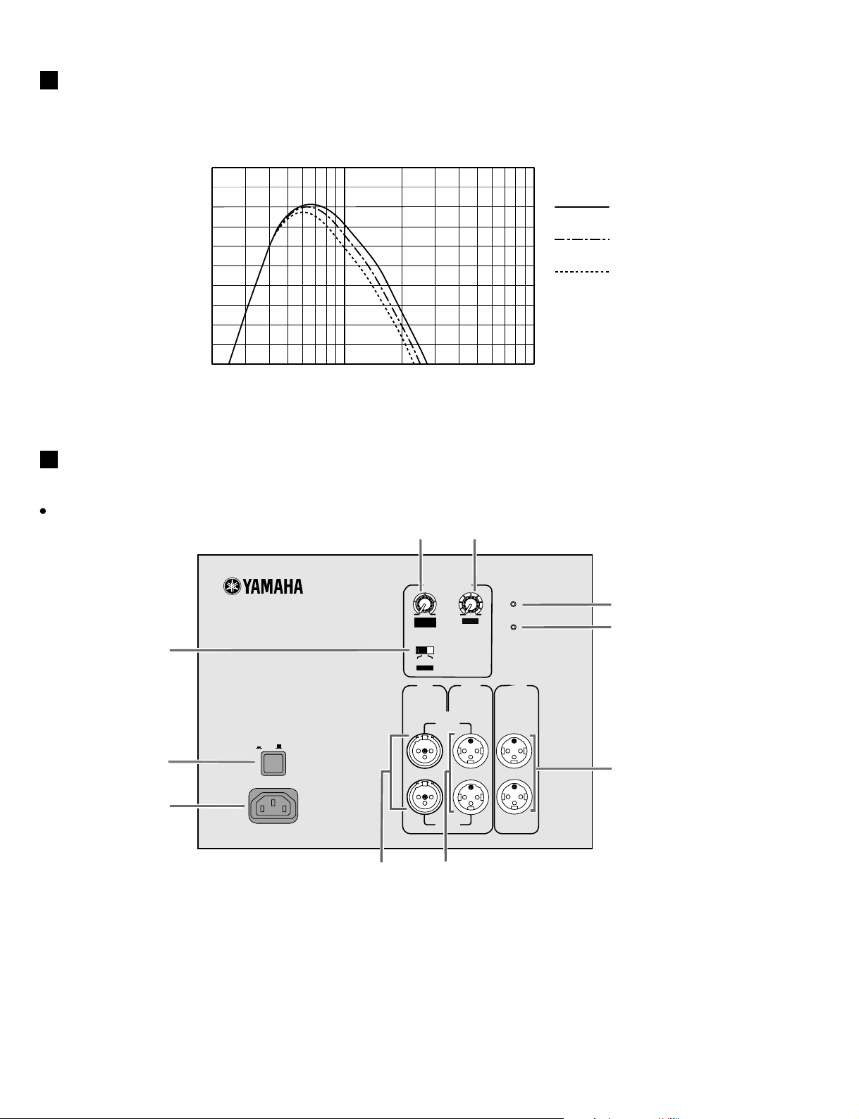
PERFORMANCE GRAPH
Standard frequency response
RESPONSE (dB)
PANEL LAYOUT
Rear Panel
+10
-10
-20
-30
-40
Cutoff Frequency
0
100Hz
90Hz
80Hz
20
1k100
FREQUENCY (Hz)
e
r
SUBWOOFER
MODEL SW500
t
POWER
ON /
OFF
q
w
AC IN
q [POWER] switch
w [AC IN] connector
e [CUTOFF FREQ.] control
r [LEVEL] control
t [PHASE] switch
y [INPUT] jacks A and B
u [OUTPUT THRU] jacks A and B
i [OUTPUT HIGH PASS] jacks A and B
o [POWER] indicator
!0 [CLIP] indicator
y
A
B
SUBWOOFER CONTROL
80
CUTOFF
FREQ.
NORM
PHASE
INPUT
(+4dB)
REV
100
PARALLEL
PARALLEL
u
POWER
0
10
LEVEL
OUTPUT
THRU
CLIP
OU TPUT
HIGH PASS
100Hz
(+4dB)
o
!0
i
4
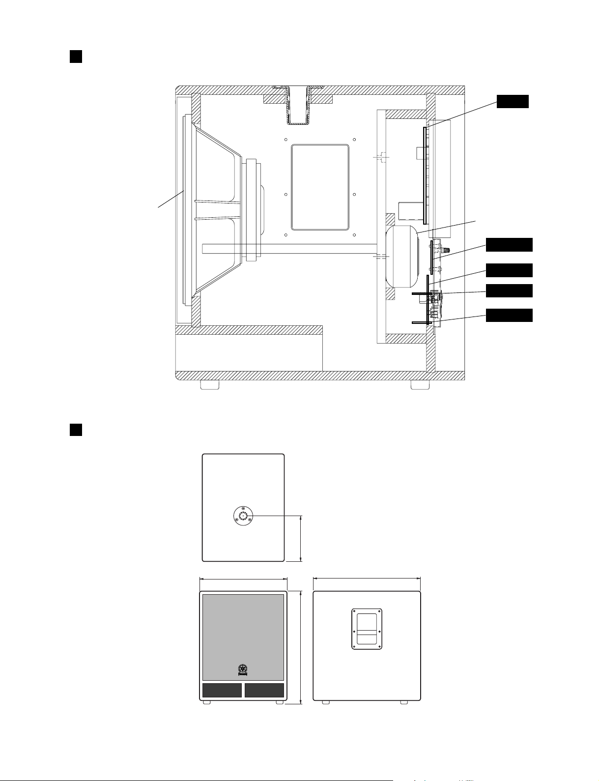
CIRCUIT BOARD LAYOUT
SW500
AMP
Power TransformerSpeaker <Woofer>
MIX 1/4
MIX 2/4
MIX 3/4
DIMENSIONS
480
MIX 4/4
250
590
619
Units: mm
5
SW500
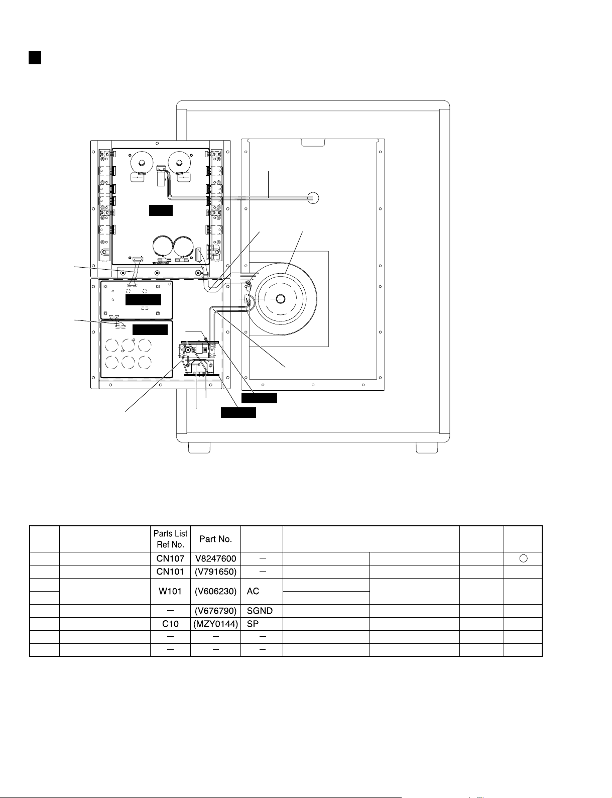
WIRING
q
w
CN102
CN101
CN201
MIX 1/4
MIX 2/4
e-2
CN107
CN203
AMP
CN202
CN106
CN105
W101BW101BW101B W101AW101AW101A
e-1
r
BL
YE
MIX 3/4
MIX 4/4
y
t
Power Transformer
u
Location
q
w
e-1
e-2
r
t
y
u
6
Unit Name
MIX 1/4 Circuit Board
MIX 2/4 Circuit Board
MIX 4/4 Circuit Board
MIX 4/4 Circuit Board
Cabinet Assembly
Power Transformer
Power Transformer
Connector
Assembly
Destination
MIX 1/4-CN107 AMP-CN201
MIX 2/4-CN101 MIX 1/4-CN102
MIX 4/4-W101A
MIX 4/4-W101B
MIX 3/4-CN105
MIX 4/4-JK107 Rear Panel (GND)
Speaker AMP-CN203
Power Transformer AMP-CN202
Power Transformer MIX 3/4-CN106
Remarks
6P-100L
4P-60L
2P
1P
2P
6P
2P
Availability
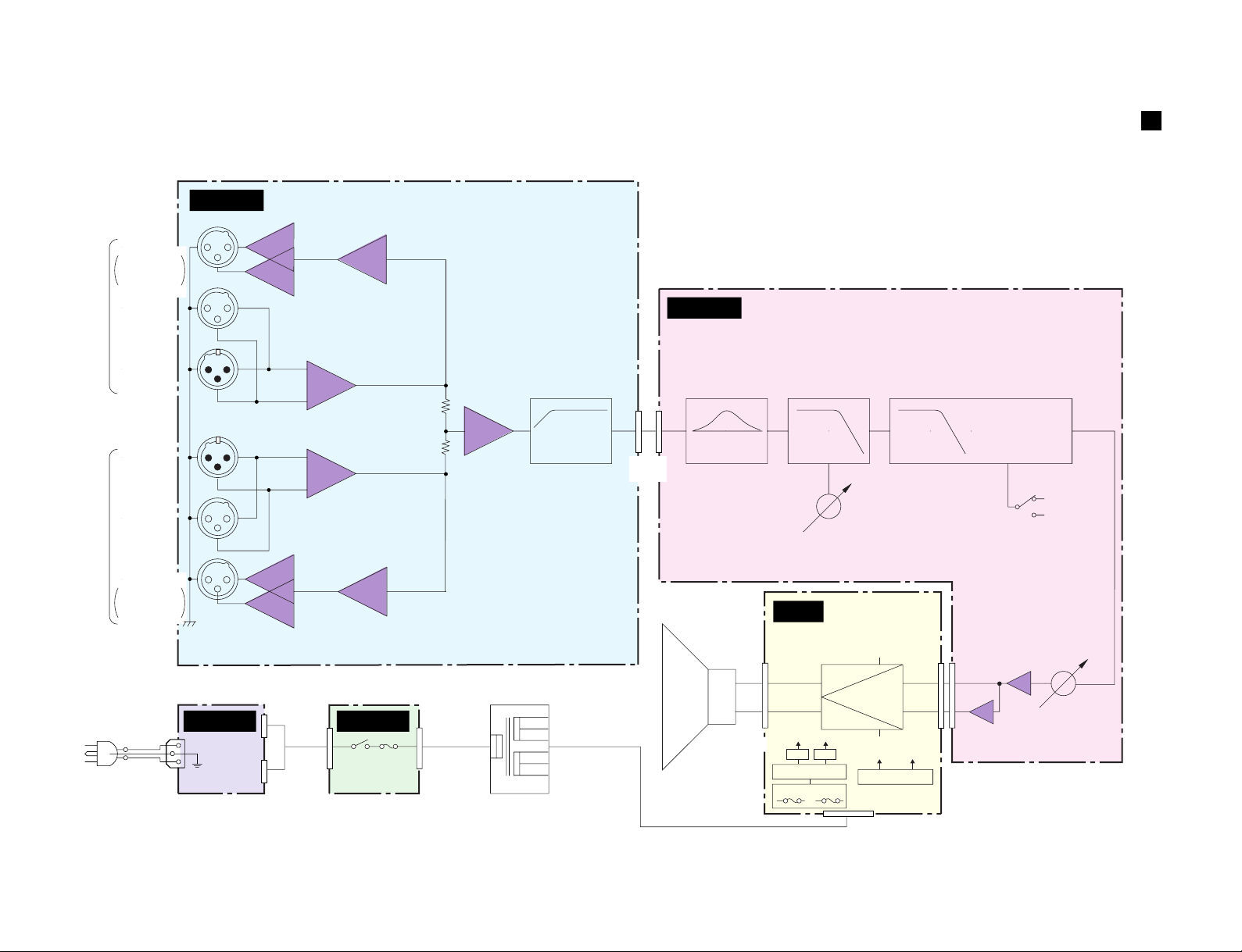
HPF
HPF
BOOST
LOW
CUT
LOW
LPF LPF
SUM
OUTPUT
(THRU)
OUTPUT
(+4dB)
INPUT
(+4dB)
INPUT
(THRU)
OUTPUT
100Hz
100Hz
PHASE
NORMAL
REVERSE
(80Hz to 100Hz)
CUTOFF FREQ.
ch A
ch B
SPEAKER
Secondary
(Woofer)
LEVEL
BTL
MIX 2/4
MIX 1/4
AMP
MIX 3/4
+
-
RECTIFIER
RECTIFIER
OUTPUT
HIGH PASS
100Hz
+4dB
Power Transformer
Primary
AC IN
MIX 4/4
HIGH PASS
100Hz
+4dB
F201 F202
JK101
JK102
JK103JK103
JK105
JK106JK106
GND
7
51 3
2
1
JK104JK104
IC104
(8P)
IC102
(8P)
5
3
1
215 373113
2
CH1
CH2
W+
W-
+B
-B
IC202IC201
+15
+15V
-15
-15V
T101
+B -B
57
21
1/7
2
6
7
IC103
(8P)
IC103
(8P)
IC105
(8P)
CN101
(4P)
CN102
(4P)
IC105
(8P)
IC106
(8P)
IC107
(8P)
IC108
(8P)
IC109
(8P)
IC109
(8P)
CN107
(6P)
CN201
(6P)
CN202
(6P)
CN203
(4P)
CN106
(3P)
CN105
(3P)
W101B
(1P)
W101A
(1P)
FG
SW101 F101
IC104
(8P)
IC101
(8P)
7
57 5
2
1
VR101
VR102
SW102
BLOCK DIAGRAM
7
SW500
SW500
DISASSEMBLY PROCEDURE
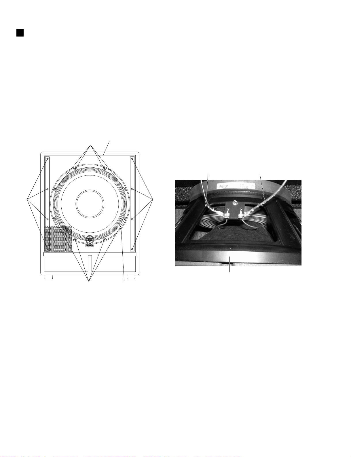
1. Speaker (Woofer) (Time required: About 10 minutes)
1-1 Remove the eight (8) screws marked [60]. The front grille
assembly can then be removed. (Fig.1)
1-2 Remove the eight (8) cap screws marked [C90]. The speaker
(woofer) can then be removed. (Fig.1)
1-3 Remove the SP connector assembly (red/black) installed to the
speaker (woofer). (Photo.1)
<Front View>
[C90]
[60] [60]
[C90]
Front Grille Assembly
Speaker (Woofer)
SP Connector
Assembly (Black)
Speaker (Woofer)
SP Connector
Assembly (Red)
Photo.1
[60]: Cup Head Tapping Screw-1
4.0X16 MFZN2BL (V8889600)
[C90]: Cap Screw
#10X1-1/2 BL Z (EKY01010)
Fig.1
8

2. Amplifier Assembly (Time required: About 5 minutes)
2-1 Remove the sixteen (16) screws marked [30]. The amplifier
assembly can then be removed. (Fig.2)
3. Power Transformer (Time required: About 10 minutes)
3-1 Remove the amplifier assembly. (See procedure 2.)
3-2 Remove the hexagonal bolt marked [A]. The power transformer
can then be removed. (Fig.3, 4)
SW500
4. AMP Circuit Board
(Time required: About 15 minutes)
4-1 Remove the amplifier assembly. (See procedure 2.)
4-2 Remove the five (5) screws marked [A80A] in right and left
each. The right and left transistor holders can then be removed.
(Fig.3)
4-3 Remove the four (4) screws marked [A90]. The AMP circuit
board can then be removed. (Fig.3)
5. MIX 1/4 Circuit Board
(Time required: About 10 minutes)
5-1 Remove the knobs marked [A150] and [A160] from the rear
panel side. (Fig.2)
5-2 Remove the amplifier assembly. (See procedure 2.)
5-3 Remove the four (4) screws marked [A190]. The MIX 1/4 circuit
board can then be removed with the four (4) PCB supports.
(Fig.2, 3)
5-4 Remove the four (4) PCB supports from the MIX 1/4 circuit
board. (Fig.3)
6. MIX 2/4 Circuit Board
(Time required: About 15 minutes)
6-1 Remove the amplifier assembly. (See procedure 2.)
6-2 Remove the twelve (12) screws marked [A100A]. The MIX 2/4
circuit board can then be removed. (Fig.2, 3)
6-3 Remove the MIX 1/4 circuit board. (See procedure 5.)
And then disconnect the connector (CN102) from the MIX 1/4
circuit board.
7. MIX 3/4 Circuit Board
(Time required: About 10 minutes)
7-1 Remove the amplifier assembly. (See procedure 2.)
7-2 Remove the two (2) screws marked [A100B]. The MIX 3/4 circuit
board and the power switch knob can then be removed.
(Fig.2, 3)
8. MIX 4/4 Circuit Board
(Time required: About 10 minutes)
8-1 Remove the amplifier assembly. (See procedure 2.)
8-2 Remove the two (2) screws marked [A80B] and the screw marked
[A130]. The MIX 4/4 circuit board and the AC inlet angle bracket
can then be removed. (Fig.2, 3)
9
 Loading...