

Page 1

YAMAHA SINGLE-AXIS ROBOT CONTROLLER
SRCP
User’s Manual
ENGLISH
E
E84-Ver. 2.04
Page 2

Page 3

General Contents
Chapter 1 OVERVIEW........................................................................................................... 1-1
1-1 Features of the SRCP Series Controller................................................................................... 1-2
1-2 Setting Up for Operation .......................................................................................................1-3
1-3 External View and Part Names ...............................................................................................1-4
1-3-1 SRCP controller ............................................................................................................................................. 1-4
1-3-2 TPB ................................................................................................................................................................ 1-7
1-4 System Configuration .............................................................................................................1-8
1-4-1 System configuration ..................................................................................................................................... 1-8
1-5 Accessories and Options ........................................................................................................ 1-9
1-5-1 Accessories .................................................................................................................................................... 1-9
1-5-2 Peripheral options ......................................................................................................................................... 1-9
Chapter 2 INSTALLATION AND CONNECTION .................................................................. 2-1
2-1 Installing the SRCP Controller................................................................................................2-2
2-1-1 Installation method ....................................................................................................................................... 2-2
2-1-2 Installation location ....................................................................................................................................... 2-2
2-2 Connecting the Power Supply ................................................................................................2-3
2-2-1 Power supply ................................................................................................................................................. 2-3
2-2-2 Connecting the power supply ........................................................................................................................ 2-3
2-2-3 Installing an external leakage breaker ........................................................................................................... 2-4
2-2-4 Installing a circuit protector .......................................................................................................................... 2-4
2-2-5 Installing current control switches ................................................................................................................ 2-5
2-2-6 Insulation resistance and voltage breakdown tests ........................................................................................ 2-5
2-3 Grounding..............................................................................................................................2-5
2-4 Connecting the SRCP to the Control Unit .............................................................................. 2-5
2-5 Connecting to the Robot ........................................................................................................ 2-6
2-5-1 Robot I/O connector and signal table ........................................................................................................... 2-6
2-5-2 Motor connector and signal table .................................................................................................................. 2-6
2-6 Connecting to the I/O. CN Connector ................................................................................... 2-7
2-7 Connecting to the EXT. CN Connector ...................................................................................2-8
2-8 Connecting to the Regenerative Unit ..................................................................................... 2-9
Chapter 3 I/O INTERFACE .................................................................................................... 3-1
3-1 I/O Signals .............................................................................................................................3-2
3-1-1 I/O. CN connector signals ............................................................................................................................. 3-2
3-1-2 EXT. CN connector signals ............................................................................................................................. 3-2
3-2 Input Signal Description ........................................................................................................ 3-3
3-2-1 Dedicated command input ............................................................................................................................ 3-3
3-2-2 General-purpose input (DI0 to DI7) .............................................................................................................. 3-6
3-2-3 SERVICE mode input (SVCE) .......................................................................................................................... 3-7
3-2-4 Interlock (LOCK) ........................................................................................................................................... 3-7
3-2-5 Emergency stop inputs 1, 2 (EMG1, EMG2) ................................................................................................... 3-7
3-3 Output Signal Description ..................................................................................................... 3-8
3-3-1 Dedicated output .......................................................................................................................................... 3-8
3-3-2 General-purpose output (DO0 to DO4) ........................................................................................................ 3-9
3-3-3 Feedback pulse output (PA±, PB±, PZ±, PZM±)............................................................................................. 3-9
3-4 I/O Circuits ..........................................................................................................................3-10
3-4-1 I/O circuit specifications ............................................................................................................................. 3-10
3-4-2 I/O circuit and connection example ............................................................................................................ 3-11
3-5 I/O Connection Diagram .....................................................................................................3-12
3-5-1 Connection to PLC output unit .................................................................................................................... 3-12
3-5-2 Connection to PLC input unit ...................................................................................................................... 3-13
3-6 I/O Control Timing Charts ................................................................................................... 3-14
3-6-1 When turning the power on ........................................................................................................................ 3-14
3-6-2 When executing a dedicated input command.............................................................................................. 3-15
3-6-3 When interlock signal is input ..................................................................................................................... 3-18
3-6-4 When emergency stop is input .................................................................................................................... 3-19
3-6-5 When alarm is issued ................................................................................................................................... 3-19
3-6-6 When executing a point movement command ............................................................................................ 3-20
i
Page 4

Chapter 4 BASIC OPERATION OF THE TPB ......................................................................... 4-1
4-1 Connecting and Disconnecting the TPB .................................................................................4-2
4-1-1 Connecting the TPB to the SRCP controller ................................................................................................... 4-2
4-1-2 Disconnecting the TPB from the SRCP controller .......................................................................................... 4-3
4-2 Basic Key Operation .............................................................................................................. 4-4
4-3 Reading the Screen ................................................................................................................ 4-5
4-3-1 Program execution screen ............................................................................................................................. 4-5
4-3-2 Program edit screen....................................................................................................................................... 4-5
4-3-3 Point edit screen (teaching playback) ............................................................................................................ 4-6
4-3-4 DIO monitor screen ...................................................................................................................................... 4-6
4-4 Hierarchical Menu Structure.................................................................................................. 4-7
4-5 Restricting Key Operation by Access Level ............................................................................. 4-8
4-5-1 Explanation of access level ............................................................................................................................ 4-8
4-5-2 Changing an access level ............................................................................................................................... 4-9
Chapter 5 PARAMETERS ....................................................................................................... 5-1
5-1 Setting the Parameters ...........................................................................................................5-2
5-2 Parameter Description ........................................................................................................... 5-3
Chapter 6 PROGRAMMING ................................................................................................. 6-1
6-1 Basic Contents ....................................................................................................................... 6-2
6-1-1 Robot language and point data ...................................................................................................................... 6-2
6-1-2 Using the TPB to enter the robot language .................................................................................................... 6-2
6-1-3 Program specifications .................................................................................................................................. 6-2
6-2 Editing Programs .................................................................................................................... 6-3
6-2-1 Creating programs after initialization ............................................................................................................ 6-4
6-2-2 Creating a new program ................................................................................................................................ 6-6
6-2-3 Adding a step ................................................................................................................................................. 6-7
6-2-4 Correcting a step ........................................................................................................................................... 6-9
6-2-5 Inserting a step ............................................................................................................................................ 6-10
6-2-6 Deleting a step ............................................................................................................................................ 6-11
6-3 Program Utility ....................................................................................................................6-12
6-3-1 Copying a program ...................................................................................................................................... 6-12
6-3-2 Deleting a program...................................................................................................................................... 6-13
6-3-3 Viewing the program information ................................................................................................................ 6-14
Chapter 7 EDITING POINT DATA ........................................................................................ 7-1
7-1 Manual Data Input .................................................................................................................7-2
7-2 Teaching Playback.................................................................................................................. 7-3
7-3 Direct Teaching ......................................................................................................................7-5
7-4 Manual Control of General-Purpose Output ..........................................................................7-7
7-5 Manual Release of Holding Brake ..........................................................................................7-8
7-6 Deleting Point Data ............................................................................................................... 7-9
7-7 Tracing Points (Moving to a registered data point) ............................................................... 7-10
Chapter 8 ROBOT LANGUAGE ............................................................................................ 8-1
8-1 Robot Language Table ............................................................................................................8-2
8-2 Robot Language Syntax Rules ................................................................................................ 8-3
8-2-1 Command statement format .......................................................................................................................... 8-3
8-2-2 Variables........................................................................................................................................................ 8-4
8-3 Program Function .................................................................................................................. 8-5
8-3-1 Multi-task function ........................................................................................................................................ 8-5
ii
Page 5

8-4 Robot Language Description .................................................................................................. 8-6
8-4-1 MOVA ........................................................................................................................................................... 8-6
8-4-2 MOVI ............................................................................................................................................................ 8-6
8-4-3 MOVF ............................................................................................................................................................ 8-7
8-4-4 JMP ................................................................................................................................................................ 8-7
8-4-5 JMPF .............................................................................................................................................................. 8-8
8-4-6 JMPB ............................................................................................................................................................. 8-9
8-4-7 L .................................................................................................................................................................... 8-9
8-4-8 CALL ............................................................................................................................................................ 8-10
8-4-9 DO .............................................................................................................................................................. 8-10
8-4-10 WAIT ........................................................................................................................................................... 8-11
8-4-11 TIMR ........................................................................................................................................................... 8-11
8-4-12 P .................................................................................................................................................................. 8-12
8-4-13 P+ ................................................................................................................................................................ 8-12
8-4-14 P- ................................................................................................................................................................. 8-12
8-4-15 SRVO ........................................................................................................................................................... 8-13
8-4-16 STOP ........................................................................................................................................................... 8-13
8-4-17 ORGN ......................................................................................................................................................... 8-14
8-4-18 TON ............................................................................................................................................................ 8-15
8-4-19 TOFF ........................................................................................................................................................... 8-15
8-4-20 JMPP ............................................................................................................................................................ 8-16
8-4-21 MAT............................................................................................................................................................. 8-17
8-4-22 MSEL ........................................................................................................................................................... 8-18
8-4-23 MOVM ........................................................................................................................................................ 8-19
8-4-24 JMPC ........................................................................................................................................................... 8-20
8-4-25 JMPD ........................................................................................................................................................... 8-20
8-4-26 CSEL ............................................................................................................................................................ 8-21
8-4-27 C .................................................................................................................................................................. 8-21
8-4-28 C+ ............................................................................................................................................................... 8-22
8-4-29 C- ................................................................................................................................................................ 8-22
8-4-30 D ................................................................................................................................................................. 8-22
8-4-31 D+ ............................................................................................................................................................... 8-22
8-4-32 D- ................................................................................................................................................................ 8-23
8-4-33 SHFT ............................................................................................................................................................ 8-23
8-5 Sample Programs ................................................................................................................. 8-24
8-5-1 Moving between two points ........................................................................................................................ 8-24
8-5-2 Moving at an equal pitch ............................................................................................................................. 8-24
8-5-3 Positioning 2 points and sending job commands to a PLC at each position ................................................. 8-25
8-5-4 Robot stands by at P0, and moves to P1 and then to P2 to pick and place a workpiece .............................. 8-26
8-5-5
Picking up 3 kinds of workpieces flowing on the front conveyor and placing them on the next conveyors while sorting ...
8-5-6 Switching the program from I/O ................................................................................................................. 8-29
8-5-7 Axis movement and I/O multi-task .............................................................................................................. 8-31
8-5-8 Turning ON general-purpose outputs during robot movement after a certain time has elapsed .................. 8-32
8-5-9 Turning ON a general-purpose output during robot movement when it has passed a specified position ..... 8-33
8-27
Chapter 9 OPERATING THE ROBOT .................................................................................... 9-1
9-1 Performing Return-to-Origin.................................................................................................. 9-2
9-2 Using Step Operation.............................................................................................................9-4
9-3 Using Automatic Operation ................................................................................................... 9-7
9-4 Switching the Execution Program........................................................................................... 9-9
9-5 Emergency Stop Function.....................................................................................................9-10
9-5-1 Initiating an emergency stop ....................................................................................................................... 9-10
9-5-2 Recovering from an emergency stop ............................................................................................................ 9-10
9-6 Displaying the Memory I/O Status .......................................................................................9-12
9-7 Displaying the Variables .......................................................................................................9-13
Chapter 10 OTHER OPERATIONS ........................................................................................ 10-1
10-1 Initialization ........................................................................................................................10-2
10-2 DIO Monitor Display ...........................................................................................................10-4
10-2-1 Display from the monitor menu .................................................................................................................. 10-4
10-2-2 Display from the DIO key operation ........................................................................................................... 10-5
10-3 System Information Display .................................................................................................10-5
10-4 SERVICE mode function .......................................................................................................10-6
10-4-1 Safety settings for SERVICE mode ................................................................................................................ 10-7
10-4-2 Enabling/disabling the SERVICE mode function ........................................................................................... 10-9
10-4-3 Setting the SERVICE mode functions ......................................................................................................... 10-11
10-5 System utilities ...................................................................................................................10-13
10-5-1 Viewing hidden parameters ....................................................................................................................... 10-13
iii
Page 6

10-6 Using a Memory Card ........................................................................................................10-14
10-6-1 Saving controller data to a memory card................................................................................................... 10-14
10-6-2 Loading data from a memory card............................................................................................................. 10-16
10-6-3 Formatting a memory card ........................................................................................................................ 10-18
10-6-4 Viewing the ID number for memory card data .......................................................................................... 10-19
10-7 Duty (load factor) monitor ................................................................................................. 10-20
10-7-1 Measuring the duty (load factor) ............................................................................................................... 10-22
10-8 Using the internal flash ROM ............................................................................................. 10-23
10-8-1 Saving the parameter data onto the flash ROM ......................................................................................... 10-24
10-8-2 Manually loading the data from flash ROM ............................................................................................... 10-26
10-8-3 Initializing the flash ROM data .................................................................................................................. 10-28
Chapter 11 COMMUNICATION WITH PC ........................................................................... 11-1
11-1 Communication Parameter Specifications............................................................................11-2
11-2 Communication Cable Specifications ................................................................................... 11-3
11-2-1 Connecting to the computer with a 25-pin D-sub connector ...................................................................... 11-3
11-2-2 Connecting to the computer with a 9-pin D-sub connector ........................................................................ 11-3
11-3 Communication Command Specifications ........................................................................... 11-4
11-4 Communication Command List ............................................................................................11-5
11-5 Communication Command Description ...............................................................................11-8
11-5-1 Robot movements ........................................................................................................................................ 11-8
11-5-2 Data handling ............................................................................................................................................ 11-17
11-5-3 Utilities ...................................................................................................................................................... 11-29
Chapter 12 MESSAGE TABLES............................................................................................... 12-1
12-1 Error Messages .....................................................................................................................12-2
12-1-1 Error message specifications ........................................................................................................................ 12-2
12-1-2 Command error message ............................................................................................................................. 12-2
12-1-3 Operation error message ............................................................................................................................. 12-3
12-1-4 Program error message ................................................................................................................................ 12-4
12-1-5 System error message .................................................................................................................................. 12-5
12-1-6 Multi-task error message ............................................................................................................................. 12-5
12-2 TPB Error Messages ..............................................................................................................12-6
12-3 Stop Messages ......................................................................................................................12-7
12-3-1 Message specifications ................................................................................................................................ 12-7
12-3-2 Stop messages .............................................................................................................................................. 12-7
12-4 Displaying the Error History ................................................................................................ 12-8
Chapter 13 TROUBLESHOOTING ........................................................................................ 13-1
13-1 If A Trouble Occurs .............................................................................................................. 13-2
13-2 Alarm and Countermeasures ................................................................................................13-3
13-2-1 Alarm specifications .................................................................................................................................... 13-3
13-2-2 Alarm message list ....................................................................................................................................... 13-4
13-3 Troubleshooting for Specific Symptom................................................................................. 13-7
13-3-1 Relating to the robot movement .................................................................................................................. 13-7
13-3-2 Relating to the I/O ...................................................................................................................................... 13-9
13-3-3 Other ......................................................................................................................................................... 13-10
13-4 Displaying the Alarm History .............................................................................................13-11
Chapter 14 MAINTENANCE AND WARRANTY .................................................................... 14-1
14-1 Warranty.............................................................................................................................. 14-2
14-1-1 Warranty description................................................................................................................................... 14-2
14-1-2 Warranty Period .......................................................................................................................................... 14-2
14-1-3 Exceptions to the Warranty ......................................................................................................................... 14-2
14-2 Replacing the System Backup Battery ..................................................................................14-3
14-3 Updating the System ............................................................................................................14-4
iv
Page 7

Chapter 15 SPECIFICATIONS ............................................................................................... 15-1
15-1 SRCP sereis .......................................................................................................................... 15-2
15-1-1 Basic specifications ..................................................................................................................................... 15-2
15-1-2 Robot number list ........................................................................................................................................ 15-3
15-1-3 LED display .................................................................................................................................................. 15-3
15-2 TPB ...................................................................................................................................... 15-4
15-2-1 Basic specifications ..................................................................................................................................... 15-4
15-3 Regenerative Unit (RGU-2) ..................................................................................................15-5
15-3-1 Basic specifications ..................................................................................................................................... 15-5
15-3-2 Dimensions .................................................................................................................................................. 15-5
Chapter 16 APPENDIX .......................................................................................................... 16-1
16-1 How to Handle Options .......................................................................................................16-2
16-1-1 Memory card ............................................................................................................................................... 16-2
16-1-2 POPCOM communication cable ................................................................................................................. 16-4
v
Page 8

MEMO
vi
Page 9

Chapter 1 OVERVIEW
Thank you for purchasing the YAMAHA single-axis robot controller SRCP series (hereafter called "SRCP controller" or simply "SRCP" or "this controller"). This manual describes SRCP controller features and operating procedures.
When used with a YAMAHA single-axis PHASER series robot, the SRCP controller performs positioning and
pick-and-place tasks of various mechanical parts and devices.
This first chapter explains basic information you should know before using the SRCP controller such as names and
functions of the various parts, steps necessary to prepare the robot for operation, and the architecture of the system
itself. Please read this chapter carefully for a basic overview of the SRCP controller.
1
OVERVIEW
1-1
Page 10

1-1 Features of the SRCP Series Controller
1-1 Features of the SRCP Series Controller
1
The SRCP series is a high-performance robot controller using a 32-bit RISC chip CPU.
When used with a YAMAHA single-axis PHASER series robot, the SRCP controller performs positioning tasks of various mechanical parts and devices. The SRCP controller also performs I/O control
of solenoid valves and sensors, and controls communication with a PC (personal computer).
Using only one SRCP controller allows configuring a complete system for simple applications such
as pick-and-place tasks.
OVERVIEW
The SRCP series has the following features:
■ A high-performance 32-bit RISC chip CPU is used for high-speed, high-precision software
servo control.
■ Program assets created with the previous SRC, SRCA, ERC, SRCH, ERCX and SRCX series
can be used without any modifications.
■ Ideal acceleration and deceleration speeds can be obtained by simply entering the number of
the robot to control and the payload parameter. No troublesome servo adjustments are required.
■ The I/O interface provides 8 input and 5 output points for general-purpose user wiring as a
standard feature.
■ The TPB programming box (option) allows interactive user operation by simple menus that
permit immediate use. The robot can also be operated from a personal computer (PC) just the
same as TPB when the POPCOM software (option) is installed in the PC.
■ Programs for robot operation can be written with an easy-to-learn robot language that closely
resembles BASIC. Even first-time users will find it easy to use.
■ Users not accustomed to robot language can use a PLC (programmable logic controller) to
directly move the robot by specifying the operation points.
■ Users can create programs and control the robot on a personal computer (PC). Communication
with the PC is performed with an easy-to-learn robot language similar to BASIC. Even firsttime users will find it easy to use.
■ A built-in multi-task function allows efficiently creating the programs.
■ The I/O interface supports pulse trains to allow position control by input of a pulse train.
NOTE
n
The SRCP controller can be operated from either a TPB (programming box) or a PC running with communication
software such as POPCOM. This user's manual mainly describes operations using the TPB. For details on
operation with POPCOM, refer to the POPCOM manual. If you want to use your own methods to operate the
SRCP controller from a PC, refer to Chapter 11 "Communications with PC" for pertinent information.
1-2
Page 11

1-2 Setting Up for Operation
1-2 Setting Up for Operation
The chart below illustrates the basic steps to follow from the time of purchase of this controller until
it is ready for use. The chapters of this user's manual are organized according to the operation procedures, and allow first time users to proceed one step at a time.
Basic steps
Operation Information to be familiar with Refer to
Installation • Installing the controller 2-1
Wiring and connection • Connecting the power supply 2-2
• Grounding 2-3
• Connecting peripheral equipment
• Understanding the I/O interface Chapter 3
Setting parameters • Understanding basic TPB Chapter 4
operations
• Setting the various parameters Chapter 5
2-4 to 2-8
1
OVERVIEW
Programming • Inputting or editing programs Chapter 6
• Editing point data Chapter 7
• Robot language
Running the robot • Return-to-origin Chapter 9
• Various operation steps
• Emergency stop
Chapter 8
1-3
Page 12

1-3 External View and Part Names
1
OVERVIEW
1-3 External View and Part Names
This section explains part names of the SRCP controller and TPB along with their functions. Note
that the external view and specifications are subject to change without prior notice to the user.
1-3-1 SRCP controller
1. Status Display Lamp
This lamp indicates the operating status of the robot and controller.
Refer to "15-1-3 LED display" for information on controller status and the matching LED
display.
2. Escape Switch (ESC switch)
Hold down this switch when connecting or disconnecting the TPB from the SRCP controller.
(See "4-1 Connecting and Disconnecting the TPB.")
3. TPB Connector
This is used to connect the TPB or the RS-232C terminal of a PC (personal computer).
4. COM Connector
This is used to connect a network system when the optional network card is installed. (This is
covered when the option is not in use.)
5. Robot I/O Connector
Input/output connector for robot peripheral device signals such as position signals.
6. I/O. CN
This is used to connect external equipment such as a PLC.
7. EXT. CN
Connector for emergency stop signal input. This connector also supplies 24V power for the
I/O devices.
8.Motor Connector
This is the power line connector for the servo motor.
9. Regenerative Unit Connector (RGEN connector)
Some types of robots require connection to a regenerative unit. In such cases, use this to connect the regenerative unit (RGU-2).
10.
Terminal Block
ACIN (L, N, )
These are terminals for supplying AC power to the SRCP controller. The ground terminal must
be properly grounded to prevent electrical shock to the human body and to maintain equipment
reliability.
NC
No connection. Do not use.
T1, T2
These are input power voltage switching terminals. When an input power voltage of AC100 to
115V is used, short the T1 and T2 terminals. When an input power voltage of AC200 to 230V
is used, leave the T1 and T2 terminals open. (SRCP-05A, 10A, 20A only)
1-4
11. Serial number nameplate
MODEL.
SER. NO.
FACTORY AUTOMATION EQUIPMENT MADE IN JAPAN
SRCP 05
370001
Controller model No.
Production No. (Serial No.)
Example:
370001
Consecutive numbers
Month of production
Year of production (lowest digit of year)
Page 13
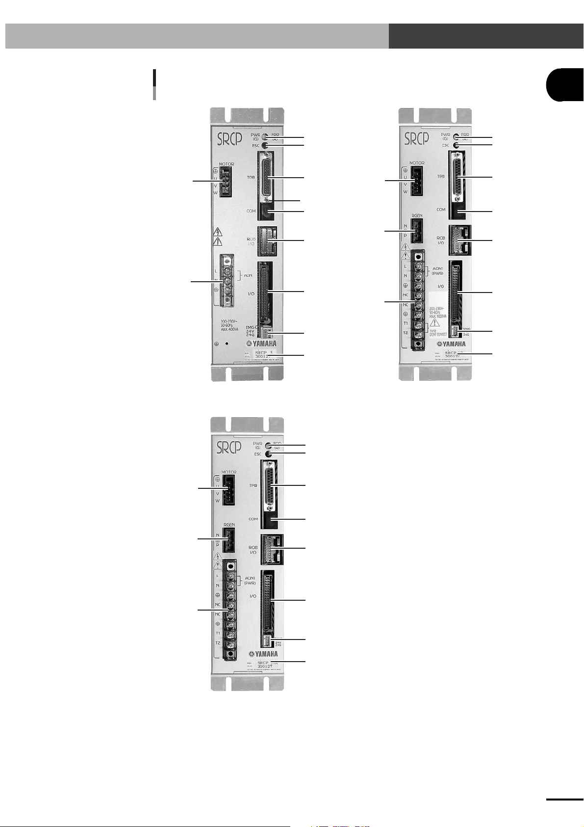
Fig. 1-1 Exterior of the SRCP controller
1-3 External View and Part Names
1
OVERVIEW
10
1
2
8
SRCP-05 SRCP-10, 20
3
4
5
6
7
11
8
9
10
1
2
3
4
5
6
7
11
8
9
10
SRCP-05A, 10A, 20A
1
2
3
4
5
6
7
11
1-5
Page 14
1-3 External View and Part Names
1
OVERVIEW
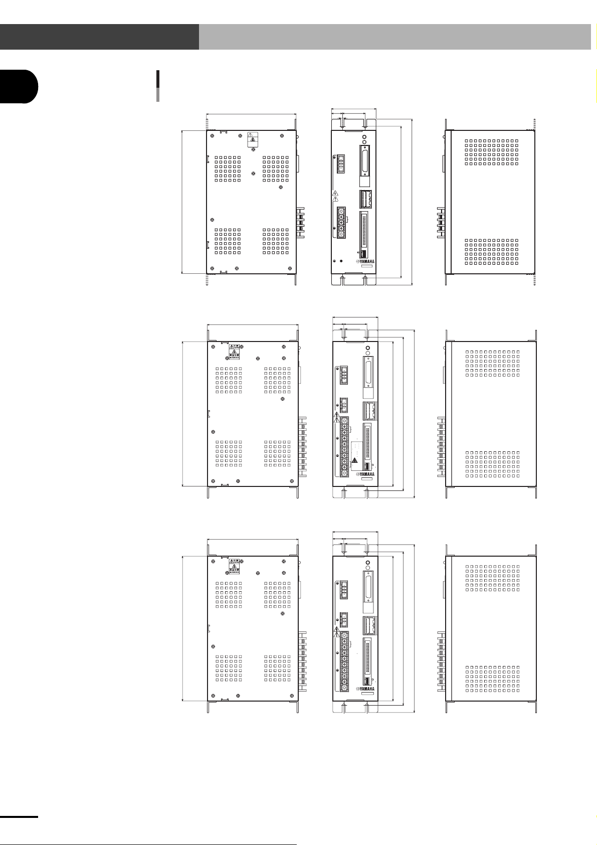
Fig. 1-2 Three-side view of the SRCP controller
SRCP-05
250
157
注意
CAUTION
高温注意
HIGH TEMPERATURE
78
19
40
5.5
SRCP
MOTOR
TPB
U
V
W
COM
ROB
I/O
L
ACIN
N
I/O
200-230V~
50-60Hz
MAX. 400VA
2
PWR
(G)
ESC
EMG
24V
24G
MODEL.
SER. NO.
FACTORY AUTOMATION EQUIPMENT MADE IN JAPAN
SRCP 05
ERR
(R)
265
290
SRCP-10, 20
250
SRCP-05A, 10A, 20A
250
157
157
78
40
19
5.5
SRCP
MOTOR
U
V
W
RGEN
N
P
L
ACIN1
(PWR)
N
NC
•
NC
200-230V~
50-60Hz
MAX.1000VA
T1
T1/T2
T2
DONT CONNECT
78
40
19
5.5
SRCP
MOTOR
U
V
W
RGEN
N
P
L
ACIN1
(PWR)
N
NC
NC
T1
T2
ERR
PWR
(R)
(G)
ESC
TPB
COM
ROB
I/O
I/O
SRCP 10
MODEL.
SER. NO.
FACTORY AUTOMATION EQUIPMENT MADE IN JAPAN
ERR
PWR
(R)
(G)
ESC
TPB
COM
ROB
I/O
I/O
SRCP 10A
MODEL.
SER. NO.
FACTORY AUTOMATION EQUIPMENT MADE IN JAPAN
250
265
290
EMG
24V
24G
250
265
290
EMG
24V
24G
1-6
Page 15
1-3 External View and Part Names
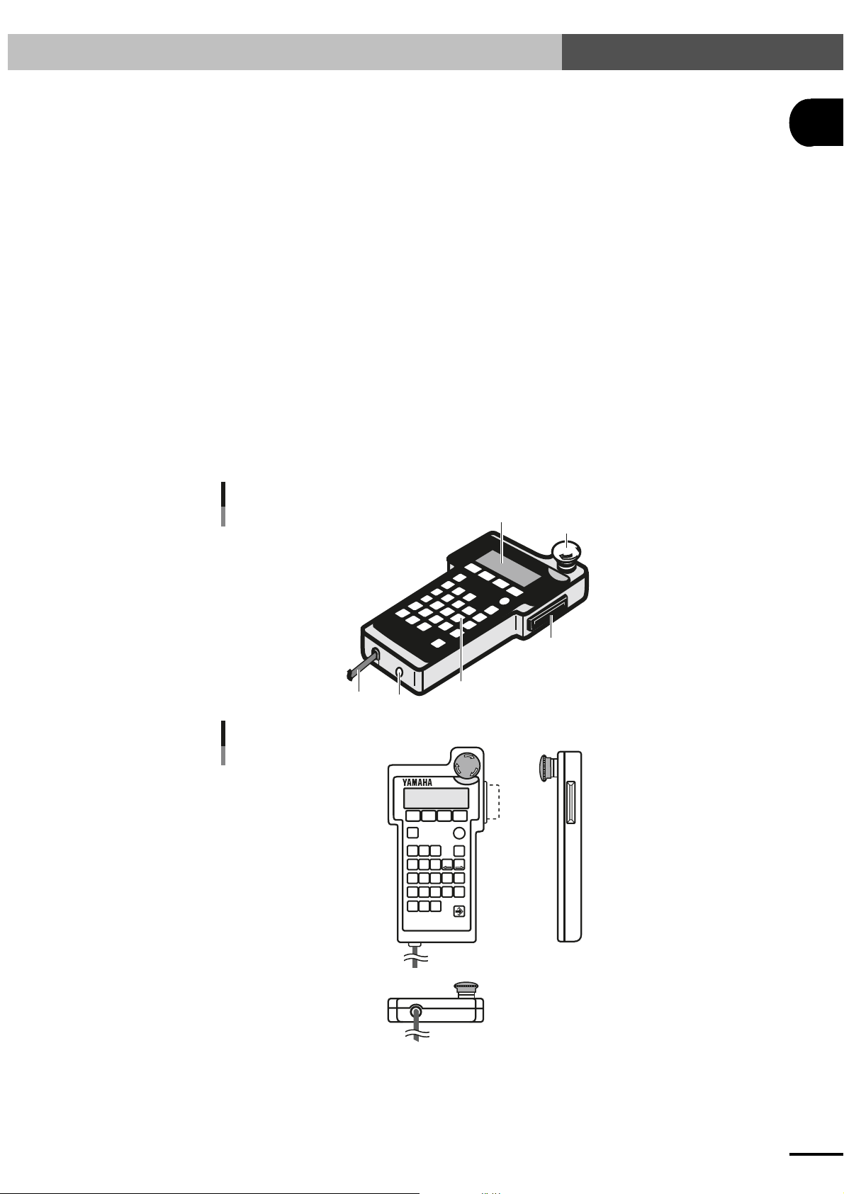
1-3-2 TPB
1. Liquid Crystal Display (LCD) Screen
This display has four lines of twenty characters each and is used as a program console.
2. Memory Card Slot
An IC memory card can be inserted here. Be careful not to insert the card upside-down.
3. Control Keys
The TPB can be operated in interactive data entry mode. Instructions are input through the
control keys while reading the contents on the LCD screen.
4. Connection Cable
This cable connects the TPB to the SRCP controller.
5. DC Power Input Terminal
Not used.
6. Emergency Stop Button
This is the emergency stop button. When pressed, it locks in the depressed position. To
release this button, turn it clockwise.
To cancel emergency stop, first release this button and then use the servo recovery command
via the I/O interface or the servo recovery operation from the TPB.
1
OVERVIEW
Fig. 1-3 Exterior of the TPB
4
5
Fig. 1-4 Three-side view of the TPB
F I
F 2
CHG
STOP
DIO
RUN
89
7
TIMR P L
456
CALL
WAIT
1
23
JMP
JMPB
JMPF
•
0
MOVF
MOVI
MOVA
TPB
F 3 F 4
DO
_
X
-
Z
Y
R
STEPUPSTEP
YAM
1
A
HA
T
6
PB
EM
G
2
3
EMG
ESC
BS
X
+
Z
Y
+
R
DOWN
1-7
Page 16
1-4 System Configuration
1
OVERVIEW
1-4 System Configuration
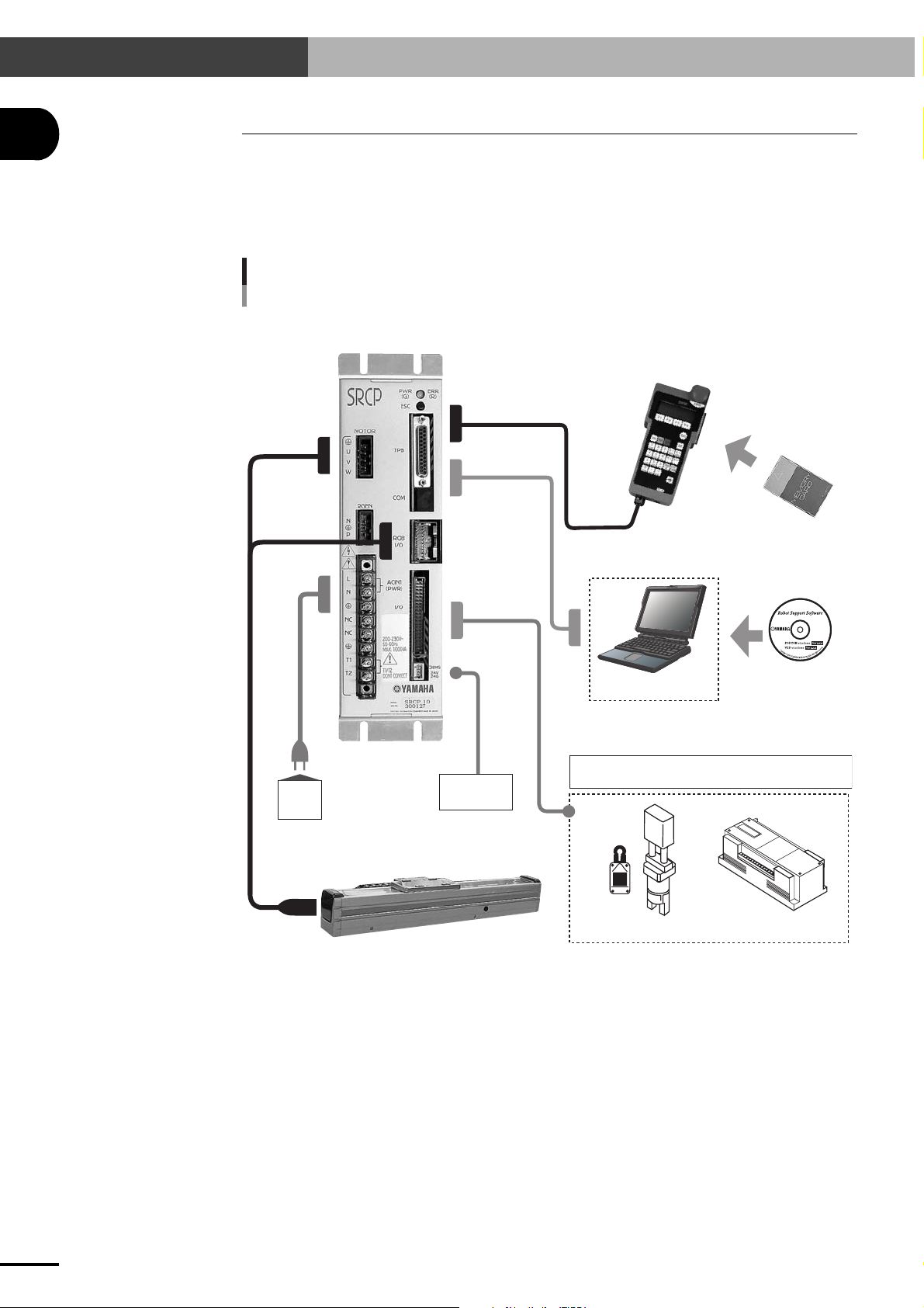
1-4-1 System configuration
The SRCP controller can be combined with various peripheral units and optional products to configure
a robot system as shown below.
Fig.1-5 System configuration diagram
SRCP Controller
or
RS-232C
communication
control
TPB programming box IC memory card
I/O control
Personal computer
General-purpose input: 8 points, dedicated input: 8 points
Power
supply
Single-axis robot (PHASER series)
* Programming box TPB and support software POPCOM are sold separately.
24VDC for
I/O devices
General-purpose output: 5 points, dedicated output: 3 points
Gripper, limit switches, etc.
Support software
POPCOM
External control
(PLC and similar units)
1-8
Page 17

1-5 Accessories and Options
1-5 Accessories and Options
1
1-5-1 Accessories
The SRCP robot controller comes with the following accessories. After unpacking, check that all
items are included.
1. EXT. CN connector
Connector : 733-104 made by WAGO 1 piece
2. I/O. CN connector with flat cable (option)
Connector : XG4M-4030-U made by OMRON 1 piece
3. RS-232C dust cover
XM2T-2501 made by OMRON 1 piece
1-5-2 Peripheral options
The following options are available for the SRCP controller:
1. TPB
This is a hand-held programming box that connects to the SRCP controller for teaching point
data, editing robot programs and operating the robot. The TPB allows interactive user operation by simple menus so that even first-time users can easily operate the robot with the TPB.
2. IC memory card
An IC memory card can be used with the TPB to back up programs, point data and parameter
data.
OVERVIEW
3. POPCOM
The POPCOM is support software that runs on a PC (personal computer) connected to the
SRCP controller. The POPCOM software allows easy editing of robot programs and operation
of a robot just the same as with a TPB.
1-9
Page 18

MEMO
1-10
Page 19

Chapter 2 INSTALLATION AND CONNECTION
This chapter contains precautions that should be observed when installing the controller, as well as procedures and
precautions for wiring the controller to the robot and to external equipment.
2
INSTALLATION AND CONNECTION
2-1
Page 20

2-1 Installing the SRCP Controller
2-1 Installing the SRCP Controller
2
2-1-1 Installation method
Using the L-shaped brackets attached to the top and bottom of the controller, install the controller
from the front or rear position. (See Fig.1-2 Three-side view of the SRCP controller.)
2-1-2 Installation location
INSTALLATION AND CONNECTION
■ Install the controller in locations where the ambient temperature is between 0 to 40°C and the
humidity is between 35 to 85% without condensation.
■ Do not install the controller upside down or at an angle.
■ Install the controller in locations with sufficient space (at least 20mm away from the wall or
other object) for good ventilation and air flow.
■ Do not install the controller in locations where corrosive gases such as sulfuric acid or hydro-
chloric acid gas are present, or in atmosphere containing flammable gases and liquids.
■ Install the controller in locations with a minimal amount of dust.
■ Avoid installing the controller in locations subject to cutting chips, oil or water from other
machines.
■ Avoid installing the controller in locations where electromagnetic noise or electrostatic noise
is generated.
■ Avoid installing the controller in locations subject to shock or large vibration.
2-2
Page 21
2-2 Connecting the Power Supply
2-2 Connecting the Power Supply
2-2-1 Power supply
Type and Item
SRCP-05
SRCP-10
SRCP-20
SRCP-05A
SRCP-10A
SRCP-20A
CAUTION
c
If the power supply voltage drops below the above range during operation, the alarm circuit will work and return
Power supply voltage
AC200 to 230V ±10%
AC200 to 230V ±10%
AC200 to 230V ±10%
AC100 to 115/200 to 230V ±10%
AC100 to 115/200 to 230V ±10%
AC100 to 115/200 to 230V ±10%
the SRCP controller to the initial state the same as just after power-on, or stop operation. To avoid this problem,
use a regulated power supply with voltage fluctuations of less than ±10%.
Since the SRCP controller uses a capacitor input type power supply circuit, a large inrush current flows when
the power is turned on. Do not use fast-blow circuit breakers and fuses. For the same reason, avoid turning the
power off and on again repeatedly in intervals of less than 10 seconds. This could harm the main circuit elements in the SRCP controller.
No. of phases
Single-phase
Single-phase
Single-phase
Single-phase
Single-phase
Single-phase
Frequency
50/60Hz
50/60Hz
50/60Hz
50/60Hz
50/60Hz
50/60Hz
Max. power consumption
400VA or less
600VA or less
1000VA or less
400VA or less
600VA or less
1000VA or less
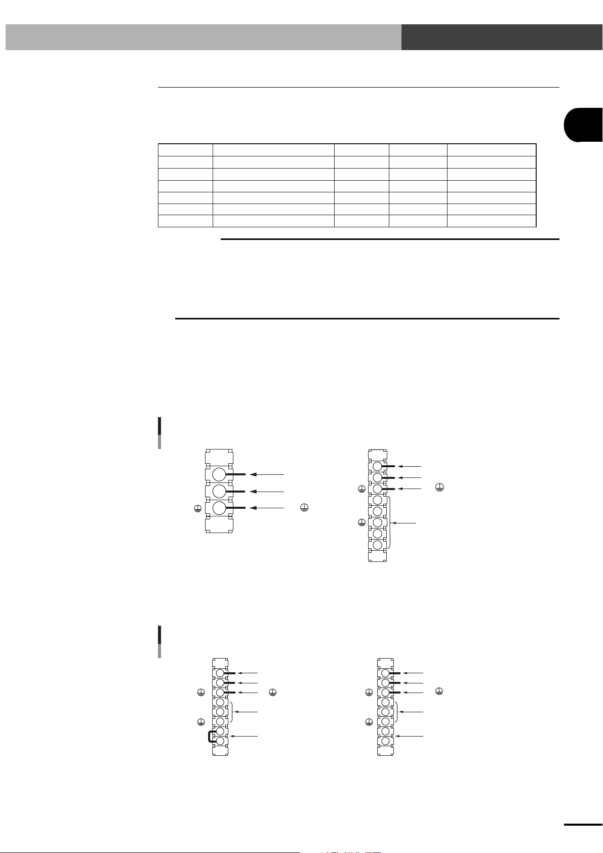
2-2-2 Connecting the power supply
Connect the power supply to the power terminal block on the front panel of the SRCP controller.
Make correct connections while referring to the printed letters and mark. Misconnections may result
in serious danger such as fire. Securely connect the end of each wire to the terminal so that it will not
come loose.
2
INSTALLATION AND CONNECTION
Fig. 2-1 Power supply connections (SRCP-05, SRCP-10, SRCP-20)
1.
1.
L
N
L (AC IN)
2.
N (AC IN)
3.
(Ground)
L
N
NC
NC
T1
T2
L (AC IN)
2.
N (AC IN)
3.
(Ground)
Do not connect.
SRCP-10, 20SRCP-05
The SRCP-05A, SRCP-10A and SRCP-20A have different connections to T1 and T2, depending on
the input voltage.
Fig. 2-2 Power supply connections (SRCP-05A, SRCP-10A, SRCP-20A)
1.
L (AC IN)
N (AC IN)
2.
3.
(Ground)
NC
NC
L
N
1.
L (AC IN)
2.
N (AC IN)
3.
(Ground)
Do not connect. Do not connect.
L
N
NC
NC
T1
T2
4. 4.
Short T1 and T2
when input voltage
is AC100 to 115V.
2
or more
0.75mm
(equivalent to AWG18)
AC 100V-115V AC 200V-230V
T1
T2
Leave T1 and T2 open
when input voltage is
AC200 to 230V.
2-3
Page 22

2-2 Connecting the Power Supply
2
CAUTION
c
The SRCP series controller does not have a power switch. Be sure to provide a power supply breaker (insulation)
of the correct specifications that will turn the power on or off to the entire system including the robot controller.
Power to EXT. CN must first be supplied before supplying power to the power supply terminal block. If this order
is reversed, an alarm (06: 24V POWER OFF) might be issued to prevent operation. (See "2.7 Connecting to the
EXT. CN Connector" in this chapter and Chapter 3, "I/O INTERFACE".)
WARNING
w
Before beginning the wiring work, make sure that the power supply for the entire system is
turned off. Doing the wiring work while power is still turned on may cause electrical shocks.
2-2-3 Installing an external leakage breaker
To ensure safety, a leakage breaker must be installed in the power supply connection section of the
robot controller. Since the robot controller drives the motors by PWM control, leakage current flows
at high frequencies. This might cause the external leakage breaker to malfunction.
When installing an external leakage current breaker, it is important to choose the optimum sensitivity
current rating (IΔn). (Check the leakage breaker manufacturer's data sheets to select the optimum
product compatible with inverters.)
Leakage current
CAUTION
c
1. Leak current was measured with a leak tester with a low-pass filter turned on (100Hz).
INSTALLATION AND CONNECTION
2. When using two or more controllers, sum the leakage current of each controller.
3. Make sure that the controller is securely grounded.
4. Stray capacitance between the cable and FG may vary depending on the cable installation condition, causing
WARNING
w
Electrical shocks, injuries or fires might occur if the motor breaks down while the robot controller
is used without installing a leakage breaker.
2-2-4 Installing a circuit protector
To ensure safety, a circuit protector must be installed in the power supply connection section of the
robot controller. An inrush current, which might be from several to nearly 20 times higher than the
rated current, flows at the instant that the SRCP controller is turned on or the robot motors start to
operate.
When installing an external circuit protector for the robot controller, select a circuit protector that
provides optimum operating characteristics.
To ensure proper operation, we recommend using a medium to slow response circuit protector with
an inertial delay function. (Refer to the circuit protector manufacturer's data sheets for making the
selection.)
SRCP 4mA (Max.)
Leak tester: Hioki Electric 3283
the leakage current to fluctuate.
2-4
Example
Rated current
SRCP 20A
WARNING
w
Electrical shocks, injuries or fires might occur if the motor breaks down while the robot controller
is used without installing a circuit protector.
Operating characteristics
Slow type with inertia delay
300% 2 sec.
(
1000% 0.01 sec.
)
Page 23
2-2 Connecting the Power Supply
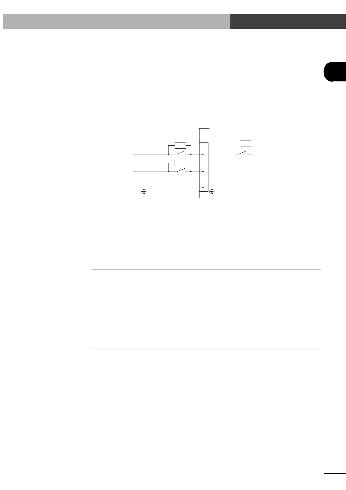
2-2-5 Installing current control switches
When controlling the power on/off of the robot controller from an external device such as a PLC, a
current control switch (contactor, breaker, etc.) may be used. In this case, the current control switch
usually creates a large on/off inrush current. To minimize this on/off inrush current, surge killers
must be installed for surge absorption. Connect a surge killer in parallel with and close to each
contact of the current control switch.
Recommended surge killer:
Okaya Electric XE1201, XE1202, RE1202
Example:
Controller
: Surge killer
L
: Contactor
2
INSTALLATION AND CONNECTION
AC IN
N
2-2-6 Insulation resistance and voltage breakdown tests
Never attempt insulation resistance tests or voltage breakdown tests on the SRCP controller. Since
capacitive grounding is provided between the controller body and 0V, these tests may mistakenly
detect excess leakage current or damage the internal circuitry. If these tests are required, please
consult your YAMAHA sales office or representative.
2-3 Grounding
The SRCP controller must be grounded to prevent danger to personnel from electrical shocks in case
of electrical leakage and prevent equipment malfunctions due to electrical noise.
We strongly recommend that Class D (grounding resistance of 100 ohms or less) or higher grounding
be provided. For grounding the controller, use the ground terminal on the power supply terminal
block.
* Class D grounding is the same as Class 3 grounding previously used.
2-4 Connecting the SRCP to the Control Unit
The SRCP controller can be operated either through the TPB programming box or through a PC
(personal computer) equipped with an RS-232C terminal.
When using the TPB, plug the TPB cable connector into the TPB connector of the SRCP controller.
(Refer to "4-1-1 Connecting the TPB to the SRCP controller".)
When using a PC, plug the RS-232C interface cable connector (25 pins) into the TPB connector of
the SRCP controller. (Refer to "11-2 Communication Cable Specifications".)
To prevent equipment malfunction due to noise, we strongly recommend that Class D (grounding
resistance of 100 ohms or less) or higher grounding be provided.
2-5
Page 24

2-5 Connecting to the Robot
2
2-5 Connecting to the Robot
First make sure that the power to the SRCP controller is turned off, and then connect the robot cable
to the robot I/O connector and motor connector on the front panel of the SRCP controller. Fully insert
the robot cable until it clicks in position.
* When the robot cable is disconnected from the controller, an alarm (15: FEEDBACK ERROR
2) is issued.
2-5-1 Robot I/O connector and signal table
Mating connector type No. : 0-174047-2 (AMP)
Mating connector contact type No. : 0-175180-2
SRCP’s connector type No. : 0-174055-2
Signal table
Terminal No.
INSTALLATION AND CONNECTION
2-5-2 Motor connector and signal table
Mating connector type No. : 1-178128-4 (AMP)
Mating connector contact type No. : 1-175218-5
SRCP's connector type No. : 1-179277-5
Signal table
Terminal No.
1
2
3
4
5
6
7
8
9
10
1
2
Signal name
PS+
PSPC+
PC+5V
GND
Z+
ZDG
DG
Signal name
FG
MU
Position SIN input (+)
Description
Position SIN input (-)
Position COS input (+)
Position COS input (-)
+5V
GND
Linear scale Z+
Linear scale Z-
Digital ground
Digital ground
Description
Frame ground
Motor U-phase output
Terminal No.
11
12
13
14
15
16
17
18
19
20
Terminal No.
3
4
Signal name
NC
ORG
+24V
+24V
0V
0V
BK+
BKNC
FG
Signal name
MV
MW
No connection
Description
Origin sensor input
Origin sensor, +24V
Origin sensor, +24V
Origin sensor, 24GND
Origin sensor, 24GND
Brake (+)
Brake (-)
No connection
Frame ground
Description
Motor V-phase output
Motor W-phase output
2-6
Page 25

2-6 Connecting to the I/O. CN Connector
2-6 Connecting to the I/O. CN Connector
The I/O. CN connector is used for connecting the SRCP controller to external equipment such as a
PLC. When using external equipment for I/O control, connect the wiring to the I/O. CN connector
(with a flat cable) supplied as an accessory and then plug it into the I/O. CN connector on the SRCP
controller.
Signals assigned to the I/O. CN connector terminals and their functions are described in detail in
Chapter 3.
The mating connector with a flat cable (option) for the I/O. CN terminal on the SRCP series controller is as follows:
Mating connector type No. : XG4M-4030-U (OMRON)
SRCP's I/O. CN connector type No. : XG4C-4034
2
INSTALLATION AND CONNECTION
B20
A20
B19
A19
B18
A18
.
.
.
.
.
.
.
.
.
B3
A3
B2
A2
B1
A1
Triangular mark
CAUTION
c
Regardless of whether I/O control is used or not, DC 24V power must be supplied to EXT. CN to enable robot
A20
A19
A18
A17
A16
A15
A6
A5
A4
A3
A2
A1
.
.
.
.
.
.
.
.
.
operation. If no power is supplied to EXT. CN, an alarm (06: 24V POWER OFF) is issued to prevent operation.
(See "2.7 Connecting to the EXT. CN Connector" in this chapter.)
If not using I/O control, disable the interlock function in PRM34 (System mode selection parameter). If the
interlock function is not disabled, it will be triggered during operation to prohibit the robot from operating.
B20
B19
B18
B17
B16
B15
B6
B5
B4
B3
B2
B1
.
.
.
.
.
.
.
.
.
2-7
Page 26
2-7 Connecting to the EXT. CN Connector
2-7 Connecting to the EXT. CN Connector
Connect an emergency stop circuit and a 24V power supply for I/O control to the EXT. CN connector. Make the necessary wiring hookup (see below) to the mating connector that comes with the
2
SRCP controller and then plug it into the EXT. CN connector. Make sure the wiring is correct since
miswiring may cause serious accidents such as fire. Regardless of whether I/O control is used or not,
24V power for I/O control must always be supplied to the EXT. CN connector.
The meaning and operation of signals assigned to each terminal on the EXT. CN connector are
explained in detail in Chapter 3, "I/O INTERFACE".
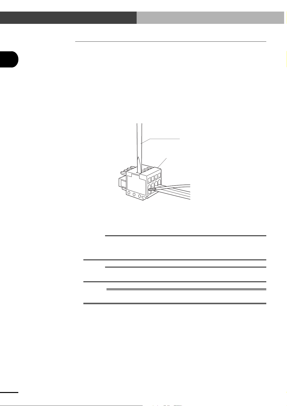
The mating connector for the EXT. CN terminal on the SRCP series controller is as follows:
Mating connector type No. : 733-104 (WAGO)
SRCP's EXT. CN connector type No. : 733-364
Slotted screwdriver
Terminal numbers are not actually
indicated, but designated from 1 to
4, from the left as viewed from the
front (wire insertion side) as shown
4
3
2
1
in the drawing.
INSTALLATION AND CONNECTION
To make the wiring hookup to the mating connector (WAGO 733-104), insert the wire lead into the
terminal slot while pressing down the internal spring with a slotted screwdriver through the top slot.
(If you have a dedicated tool, insert it into the smaller slot just above each terminal slot for wire
insertion to make a quick connection.
CAUTION
c
Regardless of whether I/O control is used or not, DC 24V power must be supplied to EXT. CN to enable robot
operation. If no power is supplied to EXT. CN, an alarm (06: 24V POWER OFF) is issued to prevent operation.
Power to EXT. CN must first be supplied before supplying AC power to the power supply terminal block. If this
order is reversed, an alarm (06: 24V POWER OFF) might be issued.
CAUTION
c
If you do not configure an emergency stop circuit, then short terminal No. 1 (EMG1) to terminal No. 2 (EMG2).
Unless these terminals are shorted, emergency stop is always activated to prohibit the robot from operating.
DANGER
w
Be sure to turn off the power to the entire robot system before doing any wiring to the SRCP
controller. Failure to do so may cause electrical shocks.
2-8
Page 27

2-8 Connecting to the Regenerative Unit
2-8 Connecting to the Regenerative Unit
Some types of robots must be connected to a regenerative unit. In such cases, use the interconnection
cable to connect the SRCP controller to the regenerative unit.
Fig. 2-3 Connecting the SRCP controller to a regenerative unit
2
INSTALLATION AND CONNECTION
Use the interconnection
cable to make connections.
2-9
Page 28

MEMO
2-10
Page 29

Chapter 3 I/O INTERFACE
The SRCP series has I/O interface connectors (EXT. CN and I/O. CN) as a standard feature. The EXT. CN is used
for emergency stop input and 24V power input for I/O control. The I/O. CN consists of an interlock input, 7
dedicated command inputs, 3 dedicated outputs, 8 general-purpose inputs, 5 general-purpose outputs, feedback
pulse outputs, etc. These I/O interfaces allow exchanging commands and data between the SRCP series and external equipment. These I/O interfaces can also directly connect to and control actuators such as valves and sensors. To
construct a system utilizing the features of the SRCP series, you must understand the signals assigned to each
terminal on the I/O. CN and EXT. CN and how they work. This chapter covers this fundamental information. This
chapter also provides examples of I/O circuit connections and timing charts for expanding the system by using a
PLC or similar devices. Refer to these diagrams and examples when creating sequence programs.
Terms "ON" and "OFF" used in this chapter mean "on" and "off" of switches connected to the input terminal when
referring to input signals. They also mean "on" and "off" of output transistors when referring to output signals.
3
I/O INTERFACE
3-1
Page 30

3-1 I/O Signals
3-1 I/O Signals
The SRCP controller has two I/O interface connectors (EXT. CN and I/O. CN) as a standard feature.
The EXT. CN is used for emergency stop input and 24V power input for I/O control. The I/O. CN is
used for interlock signal input, dedicated command input, dedicated output, general-purpose input
and output, and feedback pulse output.
3
I/O INTERFACE
3-1-1 I/O. CN connector signals
The I/O. CN connector of the SRCP controller has 40 pins, with an individual signal assigned to each
pin. The following table shows the pin number as well as the name and description of each signal
assigned to each pin. For a more detailed description of each signal, refer to "3-2 Input Signal Description" and onwards.
Pin No.
No.
1
3
5
7
9
11
13
15
17
19
21
23
25
27
29
31
33
35
37
39
n
A1
A2
A3
A4
A5
A6
A7
A8
A9
A10
A11
A12
A13
A14
A15
A16
A17
A18
A19
A20
Signal name
ABS-PT
AUTO-R
ORG-S
SERVO
BUSY
PZM+
Absolute point movement
command
Automatic operation start command
Return-to-origin command
Servo recovery command
General-purpose input 0
DI0
General-purpose input 2
DI2
General-purpose input 4
DI4
General-purpose input 6
DI6
General-purpose output 0
DO0
General-purpose output 2
DO2
General-purpose output 4
DO4
Command-in-progress output
Frame ground
FG
Signal ground
GND
Reserved (Do not use.)
NC
Reserved (Do not use.)
NC
Feedback pulse output
PA+
Feedback pulse output
PB+
Feedback pulse output
PZ+
Feedback pulse output
NOTE
Pin B8 functions as the SERVICE mode input terminal only when the SERVICE mode function is enabled.
Description
No.
10
12
14
16
18
20
22
24
26
28
30
32
34
36
38
40
2
4
6
8
Pin No.
B1
B2
B3
B4
B5
B6
B7
B8
B9
B10
B11
B12
B13
B14
B15
B16
B17
B18
B19
B20
Signal name
INC-PT
STEP-R
RESET
LOCK
DI1
DI3
DI5
DI7/SVCE
DO1
DO3
END
READY
FG
GND
NC
NC
PAPBPZ-
PZM-
Relative point movement command
Description
Step operation start command
Reset command
Interlock
General-purpose input 1
General-purpose input 3
General-purpose input 5
General-purpose input 7/SERVICE mode input
General-purpose output 1
General-purpose output 3
End-of-run output
Ready-to-operate output
Frame ground
Signal ground
Reserved (Do not use.)
Reserved (Do not use.)
Feedback pulse output
Feedback pulse output
Feedback pulse output
Feedback pulse output
3-1-2 EXT. CN connector signals
The EXT. CN connector of the SRCP controller has 4 pins, with an individual signal assigned to each
pin. The following table shows the pin number as well as the name and description of each signal
assigned to each pin. For a more detailed description of each signal, refer to "3-2 Input Signal Description" and onwards.
Pin No.
Signal name
1
EMG1
3
NOTE
n
The positive polarity of the 24V DC must be connected to pin 3 (24V) and the negative polarity to pin 4 (24G).
Emergency stop input 1 (used with
EMG2)
24V power supply for sequence input
24V
Description
Pin No.
2
4
Signal name
EMG2
24G
Emergency stop input 2 (used with
Description
EMG1)
24V power supply for sequence input
3-2
Page 31

3-2 Input Signal Description
3-2 Input Signal Description
Input signals consist of 7 dedicated command inputs, 8 general-purpose inputs and interlock signals
fed to the I/O. CN terminal, as well as an emergency stop input fed to the EXT. CN terminal.
* DI7 functions as the SERVICE mode input when the SERVICE mode function is enabled.
In this case, 7 general-purpose inputs are available.
All input circuits other than the emergency stop input use photocoupler-isolated input circuit specs.
Only the emergency stop input circuit uses contact point input circuit specs. This contact point is
directly connected to the relay coil that turns the internal motor power supply on and off.
3-2-1 Dedicated command input
The dedicated command input is used to control the SRCP controller from a PLC or other external
equipment. To accept this input, the READY, BUSY and LOCK signals must be set as follows.
■ READY signal : ON
■ BUSY signal : OFF
■ LOCK signal : ON
3
I/O INTERFACE
If the above conditions are not satisfied, then dedicated command inputs cannot be accepted even if
they are input from external equipment. For example, when the BUSY signal is on, this means that
the controller is already executing a dedicated command, so other dedicated commands are ignored
even if they are input. When the LOCK signal is off, no other commands can be accepted since an
interlock is active. (One exception is the reset and servo recovery commands that can be executed
even when the LOCK signal is off as long as the READY and BUSY signals meet the above conditions.)
A dedicated command input is accepted when the dedicated command input is switched from "off" to
"on" (at the instant the contact point closes). Whether the controller accepts the command or not can
be checked by monitoring the BUSY signal.
Note that dedicated command inputs cannot be used as data in a program.
CAUTION
c
The dedicated command inputs explained below must always be pulse inputs. In other words, they must be
turned off (contact open) after the BUSY signal turns on.
If a dedicated command input is not turned off, then the BUSY signal will remain on even when the command
has ended normally. So the next command will not be accepted.
CAUTION
c
When the SERVICE mode function is enabled, the following safety control will function. (See "10-4 SERVICE
mode function" for more details.)
• No dedicated commands can be executed in "SERVICE mode state" when command input from other than
the TPB is prohibited.
3-3
Page 32

3-2 Input Signal Description
3
■ Absolute point movement command (ABS-PT)
This command moves the robot to an absolute position specified by a point number at a specified
speed along an axis coordinate whose origin is defined as 0. The point number and speed are
specified by general-purpose input. (See "3-2-2 General-purpose input (DI0 to DI7)".)
NOTE
n
The number of general-purpose input (DI) points used to specify the point numbers and speed differs depending on
whether SERVICE mode is enabled or disabled and also on the PRM7 (I/O point movement command speed
parameter) setting. (See "3-2-2 General-purpose input (DI0 to DI7)".)
CAUTION
c
The DI0 to DI7 (DI0 to DI6 when SERVICE mode is enabled) status must be confirmed before ABS-PT is
executed. (See "3-6-6 When executing a point movement command".)
■ Relative point movement command (INC-PT)
This command moves the robot a distance specified by a point number from the current position
at a specified speed. The point number and speed are specified by general-purpose input. (See "32-2 General-purpose input (DI0 to DI7)".)
I/O INTERFACE
NOTE
n
Current position does not always indicate the actual robot position. More accurately, it is the current position data
stored in the controller. Each time a movement command is executed correctly, the current position data in the
controller is replaced with the target position data of the movement command.
Therefore, if the robot is stopped by an interlock while executing a relative movement command, re-executing the
same relative movement command moves the robot to the target position. (The robot does not move a relative
distance from the stopped position by the interlock.)
Similarly, after a robot movement command is executed, the controller still retains the target position data of that
movement command as the current position data even if you move the robot to another position by manual
operation.
When a relative movement command is executed under this condition, the robot moves the specified distance from
the target position of the movement command that was previously executed, rather than the actual robot position, so
use caution.
Current position data differs from the actual robot position when:
• Emergency stop or interlock (LOCK) was activated while the robot was moving.
• A communication command ^C (movement interruption) was transmitted while the robot was moving.
• The SERVICE mode input was changed while the robot was moving.
• The robot was moved by manual operation.
• The robot was moved by hand during servo-off (including emergency stop).
NOTE
n
The number of general-purpose input (DI) points used to specify the point numbers and speed differs depending on
whether SERVICE mode is enabled or disabled and also on the PRM7 (I/O point movement command speed
parameter) setting. (See "3-2-2 General-purpose input (DI0 to DI7)".)
CAUTION
c
The DI0 to DI7 (DI0 to DI6 when SERVICE mode is enabled) status must be specified before INC-PT is
executed. (See "3-6-6 When executing a point movement command".)
3-4
■ Automatic operation start command (AUTO-R)
This command executes the robot program continuously, starting from the current step.
All tasks are executed if the robot program is a multi-task program.
■ Step operation start command (STEP-R)
This command executes the robot program one step at a time, starting from the current step.
Only the selected task is executed even if the robot program is a multi-task program.
Page 33

3-2 Input Signal Description
■ Return-to-origin command (ORG-S)
This command returns the robot to its origin position by using stroke-end detection as the origin
detection method.
NOTE
n
The magnetic pole is detected simultaneously with return-to-origin operation. Return-to-origin is incomplete each
time the power is turned on. Always perform return-to-origin after turning on power to the controller, before
starting operation. Return-to-origin is also always incomplete after a parameter related to the origin position is
changed. Return-to-origin must be re-performed in this case.
CAUTION
c
If the robot is operated while return-to-origin is still incomplete, the necessary thrust to move the robot is
unavailable and an alarm or abnormal operation occurs. Always perform return-to-origin before starting robot
operation.
CAUTION
c
When performing return-to-origin by the stroke-end detection method, do not interrupt return-to-origin
operation while the origin position is being detected (robot is making contact with its mechanical limit).
Otherwise, the operation will stop due to a controller overload alarm and the power will need to be turned off
and back on again.
CAUTION
c
Do not continuously repeat return-to-origin operation. If return-to-origin must be repeated by the stroke-end
detection method, wait at least 5 seconds before repeating it.
3
I/O INTERFACE
■ Servo recovery command (SERVO)
After emergency stop, releasing the emergency stop button and turning this input on (closing
the contact) turns the servo power on, so the robot is ready for restart.
(As with other dedicated command inputs, the servo recovery command should be a pulse
input, so it must be turned off (contact open) when the BUSY signal turns on.)
NOTE
n
When the servo is first turned on after power-on, a sound is heard for 0.5 to 2 seconds during servo-on. This sound
is produced by a small robot movement for acquiring information needed to control the robot, and is not an
abnormal condition.
■ Reset command (RESET)
This command returns the program step to the first step of the lead program and turns off the
general-purpose outputs and the memory I/O. It also clears the point variable "P" to 0.
* When PRM33 ("Operation at return-to-origin complete" parameter) is set to 1 or 3, DO4 does
not turn off even if the reset command is executed. Likewise, when PRM46 ("Servo status
output" parameter) is set to 1, DO3 does not turn off even if the reset command is executed.
NOTE
n
The lead program is the program that has been selected as the execution program by the TPB or POPCOM. (See
"9-4 Switching the Execution Program".)
The lead program can also be selected by executing a communication command "@SWI". It may also be selected
when the program data is loaded into the SRCP controller from the memory card.
3-5
Page 34

3-2 Input Signal Description
3
3-2-2 General-purpose input (DI0 to DI7)
These general-purpose inputs are available to users for handling data input in a program.
These inputs are usually connected to sensors or switches. These inputs can also be directly connected to a PLC output circuit.
As a special function during execution of an ABS-PT or INC-PT point movement command, these
general- purpose inputs can be used to specify the point numbers and movement speed.
The number of general-purpose input (DI) points used to specify the point numbers and speed differs
depending on whether SERVICE mode is enabled or disabled and also on the PRM7 (I/O point
movement command speed parameter) setting.
For example, when PRM7 is 100 in normal mode (SERVICE mode disabled), the point numbers
should be input in binary code with DI0 to DI7 to specify P0 to P255 as shown in the table below.
If PRM7 is 0 in normal mode (SERVICE mode disabled), then point numbers should be input with
DI0 to DI5 in binary code to specify P0 to P63 as shown in the table below. The movement speed is
specified as 100% when both DI6 and DI7 are off. In other cases, it is set to the speed specified by the
parameter. (See "5-2 Parameter Description".) Also see the tables below for more details.
I/O INTERFACE
DI used to specify point numbers
DI7 to DI0 (256 points)
DI6 to DI0 (128 points)
DI5 to DI0 (64 points)
DI6 to DI0 (128 points)
DI5 to DI0 (64 points)
NORMAL mode
(SERVICE mode disabled)
SERVICE mode enabled
PRM7
100 (default setting)
1 to 99
0
100 (default setting)
1 to 99
Example of point number setting
DI No.
Point No.
P0
P1
P3
P7
P15
P31
P63
P127
P254
P255
DI7
(2
OFF
OFF
OFF
OFF
OFF
OFF
OFF
OFF
ON
ON
DI6
7
)
(2
OFF
OFF
OFF
OFF
OFF
OFF
OFF
ON
ON
ON
DI5
6
)
(2
OFF
OFF
OFF
OFF
OFF
OFF
ON
ON
ON
ON
DI4
5
)
(2
OFF
OFF
OFF
OFF
OFF
ON
ON
ON
ON
ON
DI3
4
)
(2
OFF
OFF
OFF
OFF
Example of point movement speed setting
ON
ON
ON
ON
ON
ON
DI used to specify speed
Not specified
DI7
DI7, DI6
Not specified
DI6
DI2
3
)
(2
OFF
OFF
OFF
ON
ON
ON
ON
ON
ON
ON
DI1
2
)
(2
OFF
OFF
ON
ON
ON
ON
ON
ON
ON
ON
DI0
1
0
)
(2
OFF
ON
ON
ON
ON
ON
ON
ON
OFF
ON
Speed setting method
100%
Speed setting pattern 2
Speed setting pattern 1
100%
Speed setting pattern 3
)
3-6
Speed setting pattern 1
DI7 DI6
OFF
OFF
ON
ON
Speed setting pattern 2
DI7 Movement speed
OFF
ON
Speed setting pattern 3
DI6 Movement speed
OFF
ON
Movement speed
OFF
ON
OFF
ON
100%
PRM41
PRM42
PRM43
100%
PRM7
100%
PRM7
* DI7 functions as the SERVICE mode input when the SERVICE mode function is enabled.
In this case, DI0 to DI6 can be used as the general-purpose inputs.
Page 35

3-2 Input Signal Description
3-2-3 SERVICE mode input (SVCE)
When the SERVICE mode function is enabled, DI7 functions as the SERVICE mode input (SVCE).
The SERVICE mode input is used to notify the SRCP controller whether the current state is a "SERVICE mode state". This input should be turned off (contact open) in "SERVICE mode state".
Refer to "10-4 SERVICE mode function" for details on the SERVICE mode function.
NOTE
n
Operation stops immediately if the SERVICE mode input status is changed during robot operation while the
SERVICE mode function is enabled.
3
NOTE
n
Even with the SERVICE mode function enabled, the SERVICE mode input status can be checked in the program as
DI7.
3-2-4 Interlock (LOCK)
This input is used to temporarily stop robot movement.
The robot immediately stops when this input is turned off (contact open) during execution of a dedicated I/O command or during program operation or return-to-origin operation from the TPB (or PC).
(This also interrupts the robot program operation.)
As long as this input is off (contact open), no dedicated I/O commands can be executed, and also no
programs and return-to-origin operation can be performed from the TPB (or PC). The only exceptions to this are the reset command and servo recovery command that can be executed regardless of
whether the LOCK signal is on or off. Leave this LOCK signal turned on (contact closed) during
normal operation.
Once this LOCK signal is turned off (contact open), the robot remains stopped even after this input is
turned back on (contact closed), until another command (AUTO-R, ORG-S, etc.) is input.
Changing the PRM34 (System mode selection parameter) setting enables or disables the interlock
function. (See "5-2 Parameter Description".)
3-2-5 Emergency stop inputs 1, 2 (EMG1, EMG2)
Use these inputs to trigger robot emergency stop from an external safety device (for example, safety
enclosure, manual safety switch, etc.). Servo power turns off at the same time when the contact
between EMG1 and EMG2 is open (turned off). Use a relay contact with a current capacity of at least
50mA.
To resume operation, close (turn on) the contact between EMG1 and EMG2, check that the READY
signal is turned on, and then input the servo recovery command (SERVO). The servo will turn on to
enable robot operation.
The TPB or PC can also be used to reset emergency stop when the SRCP controller is connected to
the TPB or PC.
CAUTION
c
Emergency stop inputs 1 and 2 (EMG1 and EMG2) are provided on the EXT. CN connector, and not on the I/O.
CN connector. Do not use the different inputs.
I/O INTERFACE
3-7
Page 36

3-3 Output Signal Description
3
I/O INTERFACE
3-3 Output Signal Description
The output signals consist of 3 dedicated outputs (READY, BUSY and END), 5 general-purpose
outputs, and feedback pulse outputs. In this section, terms "ON" and "OFF" mean the output transistors are "on" and "off".
3-3-1 Dedicated output
The dedicated outputs are used for exchanging signals between the SRCP controller and an external
device such as a PLC.
■ Ready-to-operate output (READY)
This output is on as long as the SRCP controller system is in normal operation. If an emergency
stop or alarm occurs, then this output turns off to let the motor idle.
•When emergency stop was triggered:
The READY signal turns on again when emergency stop is cancelled.
Operation can be restarted by input of the servo recovery command (SERVO) after canceling
emergency stop.
•When an alarm was issued:
If the READY signal is off while the robot is not in emergency stop, this means that an alarm
was issued. If this happens, correct the problem while referring to Chapter 13, "Troubleshooting".
In this case, the SRCP controller should be turned off before attempting to restart operation.
■ Command-in-progress output (BUSY)
The BUSY signal is on during execution of a dedicated command input or a command from the
TPB or PC. The BUSY signal turns on when the SRCP controller accepts a dedicated command
input. The dedicated command input should be turned off (contact open) when the BUSY signal
turns on. The BUSY signal turns off when command execution is complete. (At this point, all the
dedicated command inputs must be turned off (contact open).)
CAUTION
c
The dedicated command input must be a pulse input so that it is off when the BUSY signal turns on. If the
command input is left on, the BUSY signal cannot turn off even after the command execution is complete.
As long as the BUSY signal is on, the SRCP controller will not accept other dedicated command inputs or
commands from the TPB or PC. Avoid operating the TPB while the SRCP controller is being operated through
the I/O interface. (Doing so might cause malfunctions during data exchange with a PLC or cause communication errors on the TPB side.)
■ End-of-run output (END)
The END signal turns off when a dedicated command input is received and turns on when command execution is complete. The END signal remains off if an error occurs or an interlock or
emergency stop is triggered during command execution.
CAUTION
c
When a reset command or a movement command specifying a very small amount of movement is used, the
command execution time will be very short. In other words, the period that the END signal is off will be very
short (1ms or less in some cases).
The END signal does not change by operation from the TPB or PC.
NOTE
n
The PRM34 (system mode selection parameter) setting can be changed so that the execution result END signal
output for the completed dedicated command occurs only after the dedicated command input turns off. (See section
5-2 "Parameter Description".)
3-8
Page 37

3-3 Output Signal Description
g
3-3-2 General-purpose output (DO0 to DO4)
These general-purpose outputs are available to users for freely controlling on/off operation in a program.
These outputs are used in combination with an external 24V power supply, to drive loads such as
solenoid valves and LED lamps. These outputs of course, can be directly connected to a PLC input
circuit.
All general-purpose outputs are reset (turned off) when the SRCP controller is turned on or the
program is reset.
3
* When PRM33 ("Operation at return-to-origin complete" parameter) is set to 1 or 3, DO4 does
not turn off even if the program is reset. Similarly, when PRM46 ("Servo status output" parameter) is set to 1, DO3 does not turn off even if the program is reset.
General-purpose output (DO0 to DO4) can be used to perform the following specific functions by
parameter setting.
Function name
Alarm output
Return-to-origin complete output
Servo-ON status output
Zone output
Parameter
PRM32 (Alarm number output)
PRM33 (Operation at return-to-origin complete)
PRM46 (Servo status)
PRM53 (Zone output)
Usable general-purpose input
DO0 to DO4
DO4
DO3
DO0 to 3
For more details, see "5-2 Parameter Description".
3-3-3 Feedback pulse output (PA±, PB±, PZ±, PZM±)
This outputs current position data as differential output.
Relation between pulse output and phase
Output pin
A17:PA+
B17:PA-
A18:PB+
B18:PB-
A19:PZ+
B19:PZ-
CW direction CCW direction
I/O INTERFACE
Number of output pulses and Z-phase timing
Number of output pulses*
1 [pulses/µm]
*: Number of output pulses is a count after bein
Z-phase output timing
Every 1024 µm
multiplied by 4.
ZM phase
The ZM phase is output at the magnetic pole detection points of the PHASER series. Refer to the drawing below.
PHASER series
ZM phase
Magnetic pole detection point
:
3-9
Page 38

3-4 I/O Circuits
3
I/O INTERFACE
3-4 I/O Circuits
This section provides the SRCP controller I/O circuit specifications and examples of how the I/O
circuits should be connected. Refer to these specifications and diagrams when connecting to external
equipment such as a PLC.
3-4-1 I/O circuit specifications
■ Input Power
DC24V±10% (supplied through EXT.CN)
■ Input Circuit
Excluding emergency stop input circuit
Insulation method: Photocoupler insulation
Input terminal: Relay contact or NPN open collector transistor connected between
input terminal and 0V terminal.
Input response: 30ms max.
Input current: 5mA/DC24V
Input sensitivity: Current on: 3mA min.
Current off: 1mA max.
Emergency stop input circuit
Input terminal: Relay contact connected between emergency stop inputs 1 and 2
(between EMG1 and EMG2).
Input response: 5ms max.
Input current: 40mA/DC24V
■ Output Circuit
Insulation method: Photocoupler insulation between internal circuit and output tran-
sistor
Output terminal: NPN open collector output of all collective output common termi-
nals (0V side)
Output response: 1ms max.
Max. output current: 50mA/DC24V per output
Residual ON voltage: 1.5V max.
■ Pulse Output Circuit
Output method: Line driver (26LS31 or equivalent)
Maximum output current:
20mA
3-10
Page 39

3-4-2 I/O circuit and connection example
I/O circuit and connection example
Photocoupler
Push-button
DI
Input signal
3-4 I/O Circuits
3
I/O INTERFACE
NPN transistor
Incandescent lamp
Solenoid valve
+
-
DI
DO
DO
24V
24G
External DC24V
power supply
Pulse output circuit connection example
FG
Output signal
Controller side
Controller side
PA+
PA-
PB+
26LS32 or equivalent 26LS31 or equivalent
PB-
PZ+
PZ-
PZM+
PZM-
3-11
Page 40

3-5 I/O Connection Diagram
3
3-5 I/O Connection Diagram
3-5-1 Connection to PLC output unit
Connection to the Mitsubishi© PLC AY51 output unit
I/O INTERFACE
AY51 type output unit
Y00
TB 1
Y01
R
R
R
Y02
Y03
Y04
Y05
Y06
Y07
Y08
Y09
Y0A
Y0B
Y0C
Y0D
Y0E
Y0F
DC24V
0V
Y10
Y11
Y12
Y13
Y14
Y15
Y16
Y17
Y18
DC24V
0V
2
3
4
5
6
7
8
9
10
11
12
13
14
15
16
17
18
19
20
21
22
23
24
25
26
27
35
36
+
-
SRCP series controller
I/O. CN
DI 0
A5
DI 1
B5
DI 2
A6
DI 3
B6
DI 4
A7
DI 5
B7
DI 6
A8
DI 7
B8
LOCK
B4
SERVO
A4
RESET
B3
ORG-S
A3
STEP-R
B2
AUTO-R
A2
INC-PT
B1
ABS-PT
A1
EXT. CN
1
EMG 1
2
EMG 2
3
24V
4
24G
FG
3-12
External DC 24V
power supply
Page 41

3-5-2 Connection to PLC input unit
Connection to the Mitsubishi© PLC AX41 input unit
3-5 I/O Connection Diagram
SRCP series controller
I/O. CN
READY
BUSY
END
DO 0
DO 1
DO 2
DO 3
DO 4
B12
A12
B11
A9
B9
A10
B10
A11
TB 1
10
11
2
3
4
5
6
7
8
9
X00
X01
X02
X03
X04
X05
X06
X07
DC24V
X08
X09
AX41 type input unit
3
R
I/O INTERFACE
R
Internal
circuit
Photocoupler
24V
24G
EXT. CN
3
4
FG
+
-
External DC 24V
power supply
12
X0A
13
X0B
14
X0C
15
X0D
16
X0E
17
X0F
18
DC24V
3-13
Page 42

3-6 I/O Control Timing Charts
3-6 I/O Control Timing Charts
The following shows typical timing charts for I/O control. Refer to these diagrams when creating a
sequence program.
3-6-1 When turning the power on
3
When emergency stop is triggered:
DC24V
power supply
AC power supply
300ms or more
READY
END
I/O INTERFACE
When emergency stop is canceled:
DC24V
power supply
AC power supply
500ms or more
READY
END
When an alarm is issued:
DC24V
power supply
AC power supply
READY
END
■ The SRCP initial state depends on whether emergency stop is triggered when the power is
turned on.
When the power is turned on while emergency stop is cancelled, the SRCP controller starts
with the READY signal and also the servo turned on. (Robot is ready to operate in this state.)
In contrast, when the power is on while emergency stop is triggered, the SRCP controller starts
with the READY signal turned off under emergency stop conditions. (Robot operation is prohibited in this state.)
To enable robot operation, cancel the emergency stop to turn on the READY signal, and then
input a servo recovery command (SERVO).
■ After turning the power on, make sure that the END signal is on before inputting a dedicated
command.
■ If the READY and END signals are still off for more than the specified time after turning the
power on, this means that an alarm has occurred. If that happens, correct the problem while
referring to "13-2 Alarm and Countermeasures".
■ Before supplying AC power to the power supply terminal block, DC 24V power to EXT. CN
must be supplied.
3-14
CAUTION
c
DC 24V power to EXT. CN must first be supplied before supplying AC power to the power supply terminal block.
If this order is reversed, an alarm (06: 24V POWER OFF) might be issued.
Page 43

3-6 I/O Control Timing Charts
3-6-2 When executing a dedicated input command
■ The BUSY signal turns on when a dedicated command is received. Whether the received com-
mand has ended normally can be checked with the END signal status at the point that the
BUSY signal turns off. When the END signal is on, this means that the command has ended
normally. If it is off, the command has not ended normally.
■ The dedicated command input must be a pulse input. If the dedicated command input stays on,
the BUSY signal does not turn off even after the command has been executed.
(1)When a command with a long execution time runs and ends normally:
(Command execution is still in progress and the END signal is off when turning off
(contact open) the dedicated command input.)
Dedicated
command
BUSY
END
30ms or less
(1)At the rising edge of the dedicated command input, the END signal turns off and the BUSY
signal turns on.
(2)Turn off (contact open) the dedicated command input after checking that the BUSY signal
turns on.
(3)Wait until the BUSY signal turns off.
(4)The END signal should be on when the BUSY signal turns off, indicating that the command
has ended normally.
1ms or less 1ms or less
3
I/O INTERFACE
CAUTION
c
In the case of the automatic operation start command (AUTO-R), the END signal turns on and the BUSY signal
turns off when the program ends or a STOP statement is executed. If an endless program (one that automatically returns to the top of the program from the last step) is executed, the BUSY signal will not turn off until an
interlock or emergency stop is triggered.
3-15
Page 44

3-6 I/O Control Timing Charts
3
(2)When a command with a short execution time runs and ends normally:
(Command execution has already ended and the END signal is on before turning off
(contact open) the dedicated command input, as in the examples listed below.)
•A movement command (ABS-PT, INC-PT) for a very short distance was executed.
•A reset command (RESET) was executed.
•A step run was executed using a command with a very short execution time such as the L and
DO statements.
Dedicated
command
BUSY
I/O INTERFACE
END
30ms or less
1ms or less
30ms or less
(1)At the rising edge of the dedicated command input, the END signal turns off and the BUSY
signal turns on.
(2)Turn off (contact open) the dedicated command input after checking that the BUSY signal
turns on.
(3)Wait until the BUSY signal turns off. (The BUSY signal immediately turns off since the com-
mand execution is already complete.)
(4)The END signal should be on when the BUSY signal turns off, indicating that the command
has ended normally.
However, the PRM34 (system mode selection parameter) "bit 7 END output sequence setting at
command execution completion" setting can be changed so that the END signal turns on when the
dedicated command input turns off.
NOTE
n
The PRM34 (system mode selection parameter) "bit 7 END output sequence setting at command execution
completion" setting is supported only in Ver. 24.32 and later versions.
3-16
Dedicated
command
BUSY
END
Dedicated command
execution completion
30ms or less
1ms or less 1ms or less1ms or less
Even after dedicated command
execution completion, the END
signal does not turn on until the
dedicated command input turns
off.
Page 45

3-6 I/O Control Timing Charts
(3)When a command cannot be executed from the beginning:
(Command execution is impossible from the beginning and the END signal does not
turn on, as in the examples listed below.)
•A movement command (ABS-PT, INC-PT) was executed without return-to-origin being com-
pleted.
• An operation start command (AUTO-R, STEP-R) was executed while return-to-origin is in-
complete (except for cases where PRM48 (Pre-operation action selection parameter) is set to 1
or 3).
•A movement command (ABS-PT, INC-PT) was executed by specifying a point number whose
point data is unregistered.
•A dedicated command was executed during interlock or emergency stop (except for the reset
(RESET) and servo recovery (SERVO) commands).
•When a dedicated command input (ABS-PT, INC-PT, AUTO-R, STEP-R, ORG-S, SERVO,
RESET) was executed in "SERVICE mode state".
Dedicated
command
3
I/O INTERFACE
BUSY
END
30ms or less
1ms or less
30ms or less
(1)At the rising edge of the dedicated command input, the END signal turns off and the BUSY
signal turns on.
(2)Turn off (contact open) the dedicated command input after checking that the BUSY signal
turns on.
(3)Wait until the BUSY signal turns off. (The BUSY signal immediately turns off since the com-
mand cannot be executed from the beginning.)
(4)The END signal remains off when the BUSY signal turns off, indicating that the command
could not end normally.
3-17
Page 46
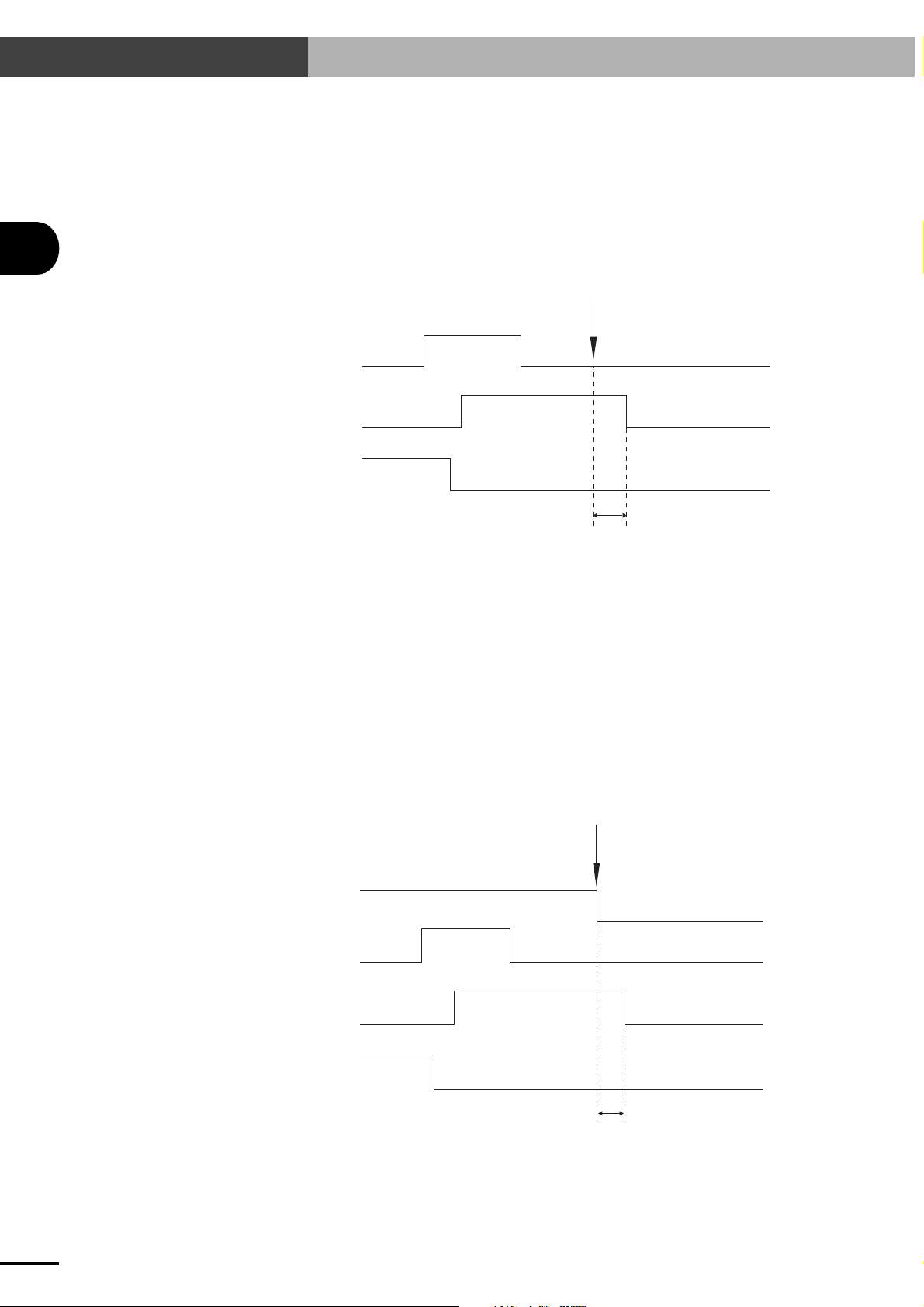
3-6 I/O Control Timing Charts
3
I/O INTERFACE
(4)When command execution cannot be completed:
(Command execution stops before completion and the END signal does not turn on, as
in the examples listed below.)
• An interlock or emergency stop was triggered during execution of a dedicated command.
•The SERVICE mode input was changed during execution of a dedicated command.
• An error was caused due to a jump to an unregistered program or point during automatic
operation.
Command execution impossible
Dedicated
command
BUSY
END
Differs according to execution command
(1)At the rising edge of the dedicated command input, the END signal turns off and the BUSY
signal turns on.
(2)Turn off (contact open) the dedicated command input after checking that the BUSY signal
turns on.
(3)Wait until the BUSY signal turns off.
(4)The BUSY signal turns off since the command execution stops before completion.
(5)The END signal remains off when the BUSY signal turns off, indicating that the command
could not end normally.
3-6-3 When interlock signal is input
Interlock
LOCK
Dedicated
command
3-18
BUSY
END
Differs according to execution command
■ When a interlock signal is input while a dedicated command is being executed, the BUSY
signal turns off. The READY and END signals remain unchanged.
Page 47
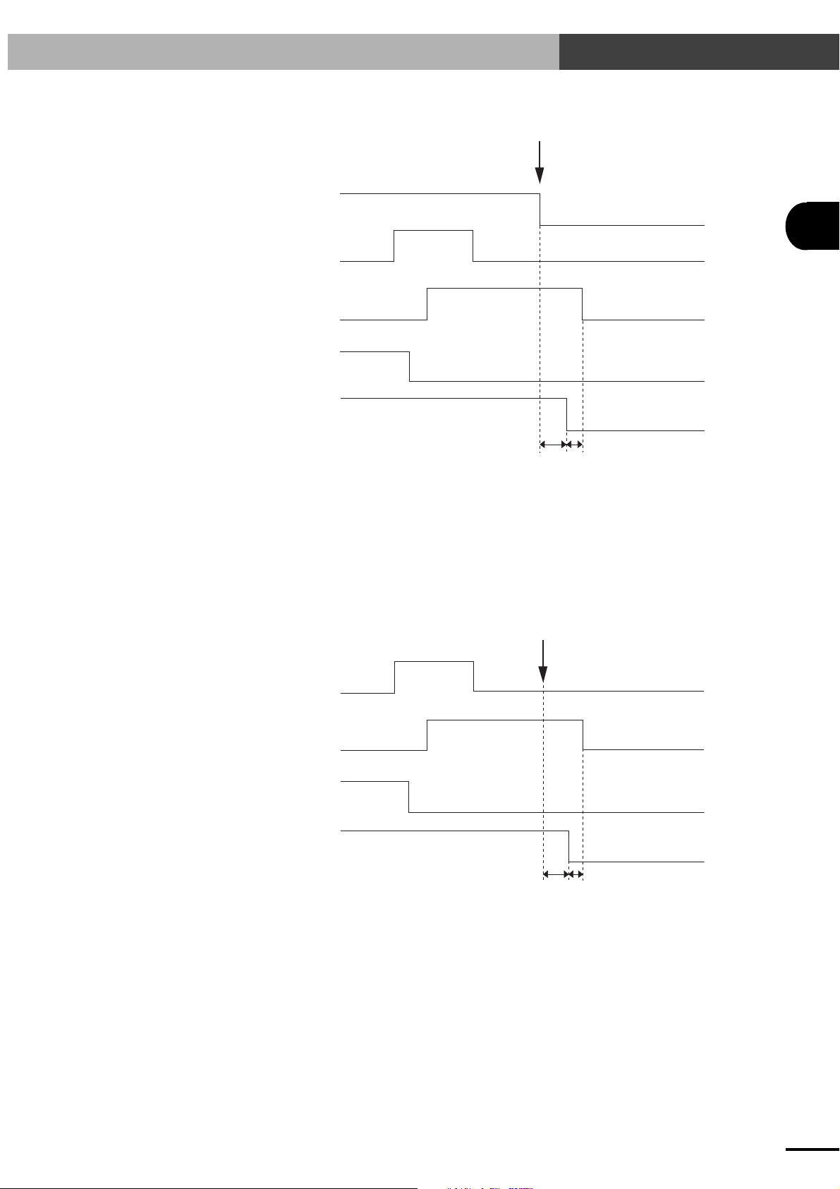
3-6-4 When emergency stop is input
EMG
3-6 I/O Control Timing Charts
Emergency stop
Dedicated
command
BUSY
END
READY
5ms or less
1ms or less
■ The READY signal turns off. The BUSY signal also turns off while a dedicated command is
being executed. The END signal remains unchanged.
■ To enable robot operation, cancel emergency stop to turn on the READY signal, then input the
servo recovery command (SERVO).
3-6-5 When alarm is issued
3
I/O INTERFACE
Alarm
Dedicated
command
BUSY
END
READY
5ms or less
1ms or less
■ The READY, BUSY and END signals all turn off.
■ Correct the problem while referring to "13-2 Alarm and Countermeasures".
3-19
Page 48

3-6 I/O Control Timing Charts
3-6-6 When executing a point movement command
■ When executing a point movement command (ABS-PT, INC-PT), the point data and speed
data must first be input before inputting the command.
The point data and speed data can be specified with DI0 to DI7 (or DI0 to DI6 when SERVICE
mode is enabled). Refer to "3-2-2 General-purpose input (DI0 to DI7)".
3
I/O INTERFACE
Point data (DI0 to 7)
Speed data
Point movement command
(ABS-PT, INC-PT)
BUSY
Actual robot operation
END
Data retention
Robot movement
30ms or more
(1)Specify the point data and speed data, using the general-purpose input DI0 to DI7. These input
conditions should be kept unchanged until the BUSY signal turns on. (If these conditions are
changed before the BUSY signal turns on, then the data might be misrecognized.)
(2)When a minimum of 30ms has elapsed, input the point movement command (ABS-PT, INC-
PT).
(3)At the rising edge of the dedicated command input, the END signal turns off and the BUSY
signal turns on.
(4)Turn off (contact open) the dedicated command input after checking that the BUSY signal
turns on.
Now, you may change the point data and speed data (DI0 to DI7) for the next movement.
(5)Wait until the BUSY signal turns off.
(6)The END signal should be on when the BUSY signal turns off, indicating that the command
has ended normally.
3-20
NOTE
n
The number of general-purpose input (DI) points used to specify the point numbers and speed differs depending on
whether SERVICE mode is enabled or disabled and also on the PRM7 (I/O point movement command speed
parameter) setting. See "3-2-2 General-purpose input (DI0 to DI7)".
Page 49

Chapter 4 BASIC OPERATION OF THE TPB
The TPB is a hand-held, pendant-type programming box that connects to the SRCP controller to edit or run programs for robot operation.
The TPB allows interactive user operation on the display screen so that even first-time users can easily operate the
robot with the TPB. This chapter describes the basic operation of the TPB.
The TPB used with the SRCP series controller must be version 12.50 or later.
4
BASIC OPERATION OF THE TPB
4-1
Page 50

4-1 Connecting and Disconnecting the TPB
4-1 Connecting and Disconnecting the TPB
4-1-1 Connecting the TPB to the SRCP controller
c
■ When the power supply to the controller is turned off
4
■ When the power supply to the controller is turned on
CAUTION
Do not modify the TPB cable or use any type of relay unit for connecting the TPB to the SRCP controller. Doing
so might cause communication errors or malfunctions.
Connect the TPB connector to the connector labelled "TPB" on the front panel of the
controller and supply power to the controller. A beep sounds for approximately 1 second and then the screen shown at the right
appears. This screen is referred to as the "Initial screen" from this point onwards.
The TPB can also be connected to the SRCP controller if the power supply to the controller is on.
In this case, hold down the ESC switch on the front panel of the controller as you plug in the TPB
connector. If the TPB is connected to the controller without pressing the ESC swith, emergency
stop might be triggered causing the robot servo to turn off. Also, if the TPB is connected while the
controller is executing a program or an I/O dedicated command, then the execution will be interrupted regardless of whether or not the ESC switch is held down.
[MENU]
select menu
1EDIT2OPRT3SYS 4MON
BASIC OPERATION OF THE TPB
CAUTION
c
Any of the messages "08: PNT DATA DESTROY", "09: PRM DATA DESTROY" or "10: PGM DATA DESTROY" may appear on the TPB when the power to the controller is turned on. (See "13-2 Alarm and Countermeasures".) If one of these messages appears, turn off the power to the controller and then turn it back on again
while the emergency stop button of the TPB is still depressed. In this state, the robot servo remains off, but the
initial screen appears on the TPB to allow key operation, so initialize and restore the data.
If the message "05: BATT. LOW-VOLTAGE" appears on the TPB when the power is turned on, turn off the
power to the controller and then turn it on again while the emergency stop button of the TPB is still depressed.
In this state, the robot servo remains off, but the initial screen appears on the TPB to allow key operation, so
make a backup of the data, and then replace the lithium battery in the controller (the lithium battery normally
lasts five years). (See "14-2 Replacing the System Backup Battery".)
If the message "SIO error" is displayed on the TPB, check whether the I/O dedicated command input is on. If
the dedicated command input is on, the TPB cannot be used, so the dedicated input must always be a pulse input
(the dedicated command input must be off when the BUSY signal turns on.) (Refer to "3-2-1 Dedicated
command input".)
4-2
Page 51

4-1 Connecting and Disconnecting the TPB
4-1-2 Disconnecting the TPB from the SRCP controller
To disconnect the TPB from the controller while a program or an I/O dedicated command is being
executed, pull out the TPB while holding down the ESC switch on the front panel of the controller.
Failing to hold down the ESC switch will trigger emergency stop in the controller and turn off the
servo.
When the TPB will be left disconnected from the controller for a long period of time, we recommend
attaching the RS-232C connector dust cover (supplied) to the TPB connector on the controller.
4
BASIC OPERATION OF THE TPB
4-3
Page 52

4-2 Basic Key Operation
4-2 Basic Key Operation
1) Selectable menu items are displayed on the 4th
line (bottom line) of the TPB screen.
Example A is the initial screen that allows you
to select the following modes.
A
[MENU]
select menu
4
BASIC OPERATION OF THE TPB
1 EDIT
2 OPRT
3 SYS
4 MON
The number to the left of each mode corresponds to the function keys from
2) On the initial screen shown in A, pressing a
function key moves to a lower level in the menu
hierarchy. (A→B→C→D)
To return to the previous screen or menu level,
press the
Menu Structure" in this chapter.)
key. (See "4-4 Hierarchical
ESC
F1
to
F4
1EDIT2OPRT3SYS 4MON
F2
↓
B
.
[OPRT]
select menu
1ORG 2STEP3AUTO
F2
C
↓
[OPRT-STEP] 100 0: 0
001:MOVA 254,100
[ 0.00]
1SPD 2RSET3CHG 4next
ESC
↑
ESC
↑
3) If an error occurs during operation, a buzzer
sounds for approximately 1 second and an error message like that shown in Example E appears on the 3rd line of the screen. If this happens, check the contents of the error message
and then press the
sage will be cleared to allow continuing operation. To correct the error, refer to the message
tables in Chapter 12.
4) If an alarm occurs during operation, its alarm
message appears on the 3rd line of the screen
and a buzzer keeps sounding. The TPB cannot
be used in this state. Turn off the power to the
controller and then correct the problem by referring to "13-2 Alarm and Countermeasures".
key. The error mes-
ESC
F3
↓
D
[OPRT-STEP] 100 0: 0
PGM No = _
(program No) 0→99
E
[OPRT-STEP]
32:origin incomplete
↑
ESC
4-4
Page 53

4-3 Reading the Screen
4-3 Reading the Screen
The following explains the basic screen displays and what they mean.
4-3-1 Program execution screen
The display method slightly differs depending on the version of TPB.
Ver. 12.50 or earlier Ver. 12.51 or later
1
[OPRT-STEP] 100 0:31
5
062:MOVA 200,100
[ 0.00]
1SPD 2RSET3CHG 4next
1. Current mode
2. Execution speed
3. No. of task being executed
4. No. of program being executed
* On TPB version 12.51 or later, when switched from the lead program to another program,
this area shows the program numbers as the "currently executed program / lead program".
5. No. of step being executed
6. Current position
2
3
[STEP] 100% 0: 31
5
4
6
062:MOVA 200,100
[ 0.00]
1SPD 2RSET3CHG 4next
1
2
3
4
4
6
BASIC OPERATION OF THE TPB
4-3-2 Program edit screen
3
1. Current mode
2. No. of program being edited
3. No. of step being edited
[EDIT-PGM] No31
062:MOVA 200,100
1MOD 2INS 3DEL 4CHG
1
2
4-5
Page 54

4-3 Reading the Screen
4-3-3 Point edit screen (teaching playback)
4
4
[EDIT-PNT-TCH](1)100
P255 = 123.45 [mm]
[ 0.00]
1CHG 2SPD 3S_SET4next
1. Current mode
2. Speed selection number
3. Speed parameter (%)
4. Edit point number
5. Current position
4-3-4 DIO monitor screen
1
2
3
5
1
2
BASIC OPERATION OF THE TPB
1. General-purpose input
From left
DI7 to DI0
2. Dedicated input
From left
Interlock (LOCK)
0: Locked state (robot movement not
possible)
1: Unlocked state (robot movement
possible)
Return-to-origin command (ORG-S)
Reset command (RESET)
Automatic operation start command
(AUTO-R)
Step operation start command (STEP-R)
Absolute point movement command
(ABS-PT)
Relative point movement command
(INC-PT)
Servo recovery command (SERVO)
DI 00000000 00000000
DO 10100000 O:0 S:1
3
3. Dedicated and general-purpose outputs
From left
4. Origin sensor status and servo status
From left
4
READY, BUSY, END, DO4 to DO0
O: Origin sensor status
0: Off (Closed)
1: On (Open)
S: Servo status
0: Servo off
1: Servo on
4-6
Page 55

4-4 Hierarchical Menu Structure
4-4 Hierarchical Menu Structure
POWER
ON
INFORMATION
(System information)
PGM
(Program Edit)
EDIT
(Editing)
OPRT
(Operation)
PNT
(Point Edit)
UTL (Utility)
ORG
(Origin Return)
STEP
(Step Run)
AUTO (Auto Run)
PRM
(Parameter Setting)
MOD (Step Edit)
INS (Step Insert)
DEL (Step Delete)
CHG (Program Change)
MDI (Manual Data Input)
TCH (Teaching Playback)
DTCH (Direct Teaching)
DEL (Delete)
COPY (Program Copy)
DEL (Program Delete)
LIST (Program List)
SPD (Execution Speed Change)
RSET (Program Reset)
CHG (Program Change)
VAL (Variable Monitor)
S_ON (Servo ON)
CHGT (Task Change)
MIO (Memory IO Monitor)
PRM1 (No.0~63)
PRM2 (No.64~)
CHG (Point Change)
CHG (Point Change)
SPD (Speed Change)
S_SET (Speed Set)
DO (General-purpose Output Control)
TRC (Point trace)
CHG (Point Change)
DO (General-purpose Output Control)
BRK (Brake)
SPD (Execution Speed Change)
RSET (Program Reset)
CHG (Program Change)
VAL (Variable Monitor)
S_ON (Servo ON)
CHGT (Task Change)
MIO (Memory IO Monitor)
4
BASIC OPERATION OF THE TPB
PGM (Program)
PNT (Point)
PRM (Parameter)
ALL (All Data)
ALOD (Automatic Load)
EDIT (Editing)
OPRT (Operation)
SYS (System)
CARD (Memory Card)
SET (Enable/Disable Setting)
(Limitation to Operating Device)
DEV
SPD (Speed Limitation)
(Step Run/Auto Run Limitation)
RUN
HtoR (Hold-to-Run Setting)
ALM (Alarm)
ERR (Error)
SYS
(System)
MON
(Monitor)
B.UP
(Backup)
INIT (Initialization)
SAFE
(Safety Setting)
OPT (Option)
UTL (Utility)
DIO (DIO Monitor)
DUTY (DUTY Monitor)
SAVE (Save)
CARD
(Memory card)
FROM
(Flash ROM)
PGM (Program)
PNT (Point)
PRM (Parameter)
ALL (All Data)
ACLV (Access Level)
SVCE (SERVICE mode)
(Hidden parameter display)
HDPR
REC (Record)
RUN (Monitor Start)
STOP (Monitor Stop)
RSLT (Result Display)
LOAD (Load)
FMT (Format)
ID (Control No.)
SAVE (Save)
LOAD (Load)
INIT (Initialization)
The menu hierarchy slightly differs depending on the versions of the controller and TPB.
4-7
Page 56

4-5 Restricting Key Operation by Access Level
4
4-5
Restricting Key Operation by Access Level
The TPB key operations can be limited by setting the access levels (operation levels).
A person not trained in robot operation might accidentally damage the robot system or endanger
others by using the TPB incorrectly. Set the access levels to restrict TPB key operations and prevent
such accidents.
NOTE
n
The access level settings are protected by a password so that changes cannot be instantly made.
4-5-1 Explanation of access level
The access levels can be set individually for editing, operation, system and memory card.
The details of the key operations limited at each level are explained below.
Editing
Level
0
1
2
3
All operations are permitted.
Program editing is prohibited.
(Program data can be checked.)
In addition to Level 1, point data editing, manual release of brake and point trace (movement to
registered data point) are prohibited.
X
X
-
(The and keys can be used to move the robot and general-purpose outputs can be controlled.)
Any operation in EDIT mode is prohibited. (Cannot enter EDIT mode.)
+
Z
Z
Description
BASIC OPERATION OF THE TPB
Operation
Level
0
All operations are permitted.
1
Changing the execution speed and program is prohibited.
In addition to Level 1, automatic operation, step operation and program reset are prohibited.
2
(Return-to-origin can be performed and variables can be monitored.)
3
Any operation in OPRT mode is prohibited. (Cannot enter OPRT mode.)
System-related data
Level
0
All operations are permitted.
1
Initialization is prohibited.
In addition to Level 1, changing the parameters and setting the option units are prohibited.
2
(Parameter data and option unit settings can be checked.)
Parameter editing, initialization and option setting are prohibited.
3
(Cannot enter SYS-PRM, SYS-INIT and SYS-OPT modes.)
Description
Description
4-8
Page 57

Memory card
4-5 Restricting Key Operation by Access Level
Level
0
All operations are permitted.
Loading the parameters and all data to the SRCP is prohibited.
1
(Point data or program data can be loaded.)
Loading any data to the SRCP is prohibited.
2
(Data can be saved and the memory card formatted.)
Use of memory card is prohibited.
3
(Cannot enter SYS-B.UP mode.)
4-5-2 Changing an access level
1) Press
2) Press
F3
(SYS) on the initial screen.
(next) to switch the menu display
F4
and then press
F1
(SAFE).
Description
4
BASIC OPERATION OF THE TPB
[MENU]
select menu
1EDIT2OPRT3SYS 4MON
[SYS]
select menu
3) When the password entry screen appears, enter
the password and press .
4) When the password is accepted, the screen
shown on the right appears.
Press
(ACLV) here.
F1
1SAFE2OPT 3UTL 4next
[SYS-SAFE]
Password: 24.00_
input password
[SYS-SAFE]
select menu
1ACLV2SVCE
4-9
Page 58

4-5 Restricting Key Operation by Access Level
4
BASIC OPERATION OF THE TPB
5) Select the item you want to change.
To change the access level for editing, press
(EDIT).
F1
To change the access level for operation, press
(OPRT).
F2
To change the access level for system-related
data, press
To change the access level for memory card,
press F4(CARD).
6) The currently set access level appears.
To change this setting, use the number key to
enter the access level and then press .
7) When the access level has been changed, the
memory write screen appears.
To save the change permanently (retain the
change even after the controller power is turned
off), press
To save the change temporarily (retain the
change until the power is turned off), press
(CHG).
F2
To cancel changing of the setting, press
(CANCEL).
F3
F3
F1
(SYS).
(SAVE).
[SYS-SAFE-ACLV]
select menu
1EDIT2OPRT3SYS 4CARD
[SYS-SAFE-ACLV-EDIT]
access level : 0
all access OK
[SYS-SAFE-ACLV-EDIT]
access level : 1
change PGM invalid
1SAVE2CHG 3CANCEL
8) When writing is complete, the screen returns
to step 6.
[SYS-SAFE-ACLV-EDIT]
access level : 1
change PGM invalid
NOTE
n
The password is identical to the SRCP controller's version number. For example, if the controller version is 24.00,
enter 24.00 as the password. Once the password is accepted, it will not be requested unless the TPB is disconnected
from the controller or the controller power is turned off.
NOTE
n
To avoid access level conflict between operation and others, the access levels may be automatically adjusted. For
example, if the access levels related to editing, system and memory card are "0", they are automatically changed to
"1" when the operation-related access level is "1" or "2" or "3". The access levels remain unchanged if they are "1"
or "2" or "3".
4-10
Page 59

Chapter 5 PARAMETERS
The SRCP controller uses a software servo system, so no adjustment of hardware components such as potentiometers
or DIP switches are required. Instead, the SRCP controller uses parameters that can be easily set or changed by the
TPB or PC (personal computer).
This chapter contains a detailed description of each of the parameters, and explains how to use the TPB to change
and specify parameter settings.
SAFETY
Errors such as motor overload are detected by the software, so the controller parameters must be set correctly to
match the connected robot model. The parameters are initialized to match the robot model when the robot is shipped,
so confirm them before starting use. If there is any trouble, please contact our sales office or sales representative.
5
PARAMETERS
5-1
Page 60
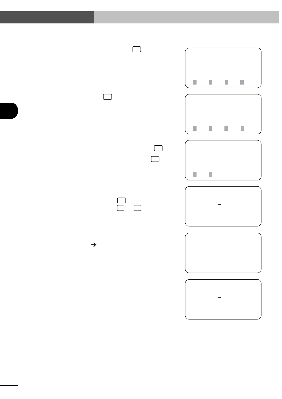
5-1 Setting the Parameters
5-1 Setting the Parameters
5
PARAMETERS
1) On the initial screen, press F3 (SYS).
2) Next, press F1 (PRM).
3) Select the parameter group you want to edit.
When editing PRM0 to PRM63, press
(PRM1).
When editing PRM64 onward, press
(PRM2).
F1
F2
[MENU]
select menu
1EDIT2OPRT3SYS 4MON
[SYS]
select menu
1PRM 2B.UP3INIT
4next
[SYS-PRM]
select menu
1PRM1 2PRM2
4) The current PRM0 (robot type number ) setting appears on the screen. (The PRM64 set-
F2
ting appears when
in step 3. ) Use the
the parameters until you find the parameter you
want to set.
5) When the desired parameter is displayed, enter
the new value with the number keys and then
press
6) When the setting is complete, the cursor moves
back to the beginning of the parameter data.
.
(PRM2) was pressed
STEP
UP
and
STEP
keys to scroll
DOWN
[SYS-PRM-PRM1]
PRM0 = 20
robot type
read only
[SYS-PRM-PRM1]
PRM1 = 450_ [mm]
(+)soft limit
range -9999→9999
[SYS-PRM-PRM1]
PRM1 =
450 [mm]
(+)soft limit
range -9999→ 9999
5-2
Page 61

5-2 Parameter Description
5-2 Parameter Description
The parameters are described in order below.
CAUTION
c
Parameters not displayed on the TPB screen are automatically set or optimized to match the robot type when the
robot parameters are initialized. You usually do not have to change these parameter settings.
If for some special reason you need to change or check these hidden parameters, use any of the following
methods.
• Turn on the power to the controller while holding down the
• Connect the TPB to the controller while holding down the
• Use the system utility mode that allows you to display hidden parameters. (See "10-5-1 Viewing hidden
parameters".)
Take extra caution when handling hidden parameters.
key on the TPB.
ESC
key on the TPB.
ESC
5
PRM0: Robot type number
This parameter shows the robot number currently used. (See "15-1-2 Robot number list".)
This is a read-only parameter. When changing the robot number or if the memory contents
are corrupted, perform parameter initialization. (See "10-1 Initialization".)
PRM1: (+) soft limit
The + side robot movement range is set.
Set a suitable value for safety purposes.
Input range: -9999 to 9999 (mm)
Default value: Depends on robot type.
CAUTION
c
The soft limit will not work unless return-to-origin has been completed.
PRM2: (-) soft limit
The - side robot movement range is set.
Set a suitable value for safety purposes.
Input range: -9999 to 9999 (mm)
Default value: Depends on robot type.
CAUTION
c
The soft limit will not work unless return-to-origin has been completed.
PARAMETERS
5-3
Page 62

5-2 Parameter Description
5
PARAMETERS
PRM3: Payload
This specifies the total weight of the workpiece and tool attached to the robot. In cases
where this weight varies, enter the maximum payload.
Based on this parameter, the controller determines the optimum acceleration speed for the
robot, so ensure that the correct payload is set. If set too small, abnormal vibration or
overheat may occur resulting in troubles with the robot or controller. Conversely, if this
parameter is larger than the actual payload, a loss of the cycle time occurs which lowers
productivity.
Input range: Depends on robot type. Units are in kilograms (kg).
Default value: 0
* This parameter is set to maximum payload when the controller is shipped from factory.
PRM4: Acceleration
This parameter sets the acceleration.
The controller will automatically set optimum acceleration according to the robot type
and payload. If you want to increase the initial acceleration setting, manually enter the
proper value by referring to the robot user's manual.
Input range: 1 to 200 (%)
Default value: 100
CAUTION
c
If acceleration is too rapid, problems such as abnormal vibrations and reduced service life of the robot might
result.
PRM5: Return-to-origin direction
This parameter sets the return-to-origin direction.
Normally, return-to-origin is performed toward the L side when this parameter is set to 1,
and toward the R side when set to 1. (See our robot product catalog to check the L and R
sides.)
Input range: 0 or 1
Default value: Depends on robot type.
PRM6: Positioning-completed pulse
This specifies the range in which the controller determines that positioning is complete.
When a movement command is executed, the robot moves toward the target position. The
controller then determines that the positioning has been completed when the remaining
distance to the target position is within this parameter setting. However, the robot continues moving until it reaches the target position even after the robot enters the "positioningcompleted pulse" range.
Since executing the next movement command is not allowed until the positioning is complete, setting a large value for this parameter can reduce cycle time in cases where critical
positioning accuracy is not required.
Input range: 1 to 4000 (pulses)
Default value: 80
* If the range specified by this parameter is larger than the range of the OUT valid posi-
tion, the controller does not decide that the "positioning-completed pulse" range is entered until the axis reaches the OUT valid position.
5-4
Page 63

5-2 Parameter Description
PRM7: I/O point movement command speed
This parameter sets the movement speed to execute a point movement command (ABSPT, INC-PT) and also determines the number of points that can be used with a point
movement command. (See "3-2-2 General-purpose input (DI0 to DI7)".)
Input range: 0 to 100 (%)
Default value: 100
PRM8: No. of conditional input points
This parameter specifies the number of effective points for the third data conditional input
for executing the JMPF statement of the robot language.
For example, when the default setting is selected for this parameter, the four points from
DI0 to DI3 are used as the conditional inputs for the JMPF statement.
Input range: 1 to 8 (points)
Default value: 4
No. of conditional input points versus general-purpose input and setting range
5
PARAMETERS
No. of conditional input points
1
2
3
4
5
6
7
8
NOTE
n
When SERVICE mode is enabled, DI7 functions as a service mode input (SVCE). Because of this, the DI7 status
will be the same as SERVICE mode input (SVCE) status when the number of conditional input points is 8.
General-purpose input Setting range
DI0
DI0 to DI1
DI0 to DI2
DI0 to DI3
DI0 to DI4
DI0 to DI5
DI0 to DI6
DI0 to DI7
0 to 1
0 to 3
0 to 7
0 to 15
0 to 31
0 to 63
0 to 127
0 to 255
PRM9: MOVF speed
This sets the speed at which the robot moves when the program language MOVF statement is executed.
Input range: Depends on robot type. (mm/sec)
Default value: 10
PRM10: Return-to-origin speed
This specifies the movement speed during return- to-origin.
Input range: 1 to 100 (mm/sec)
Default value: 20
CAUTION
c
When the return-to-origin speed is increased, an alarm might be issued during return-to-origin depending on
the robot type. We recommend using the default value as much as possible.
5-5
Page 64

5-2 Parameter Description
5
PRM11: No. of encoder pulses (4✕ mode)
This parameter indicates the constant that is determined by the linear scale.
Default value: Depends on robot type.
PRM12: Lead length
This parameter indicates the constant that is determined by the linear scale.
Default value: Depends on robot type.
PRM13: Origin detection method
This parameter specifies the origin (reference point) detection method. The SRCP controller uses the stroke-end detection method.
Default value: 1 (Stroke-end detection method)
CAUTION
c
The origin detection method is predetermined by the machine specifications. Do not change the default setting.
If changed inadvertently, serious problems might occur with the robot and controller.
PARAMETERS
PRM14: Overload current
This sets the reference current value used to detect an overload.
Default value: Equal to the motor rated current.
PRM15: Overload time
This specifies conditions such as time required to detect an overload.
The default value is set so that an overload alarm is issued when a current three times
higher than the overload current (PRM14) flows for a period of 3 seconds or an equivalent
condition is detected.
Default value: 240
PRM16: Current limit
This sets the maximum motor input current.
Default value: Depends on robot type.
PRM17: Speed proportional gain
This sets the speed control gain. Typically, PRM17 and PRM18 should be input at a ratio
of 3 : 2.
Generally, the larger the gain, the higher the acceleration will be. However, if the gain is
set too high, abnormal oscillation or noise might be generated, causing serious problems
in the robot and controller. Use caution when selecting this parameter to avoid such problems.
5-6
Default value: Depends on robot type.
Page 65

PRM18: Speed integration gain
This sets the speed control gain. Typically, PRM17 and PRM18 should be input at a ratio
of 3 : 2.
Generally, the larger the gain, the higher the acceleration will be. However, if the gain is
set too high, abnormal oscillation or noise might be generated, causing serious problems
in the robot and controller. Use caution when selecting this parameter to avoid such problems.
Default value: Depends on robot type.
PRM19: Position proportional gain
This sets the position control gain.
If this parameter is changed carelessly, serious problems may occur in the robot and controller.
5-2 Parameter Description
5
Default value: Depends on robot type.
PRM20: OUT valid position
This specifies the range in which the controller determines that movement command is
complete.
When a movement command is executed, the robot moves toward the target position. The
controller then determines that the movement command has ended when the remaining
distance to the target position is within this parameter setting. The controller then initiates
the subsequent step processing when the robot reaches this OUT valid position, so setting
this parameter to a larger value can reduce cycle time.
However, if the subsequent command is a movement command, it is not executed until the
ongoing positioning is complete.
Input range: 0 to 9999 (mm)
Default value: 1
PRM21: Position data unit
This parameter sets the units in which point data is to be displayed. Do not change this
parameter for the PHASER series. Always use the default value.
Default value: 0 (shown in mm)
CAUTION
c
Do not change this parameter for the PHASER series.
PARAMETERS
PRM22: English/Japanese selection
This parameter sets the language for the response messages displayed on the TPB or handled by RS-232C communications.
Input range: 0 or 1
Meaning: 0: English
1: Japanese
Default value: 0
PRM23: Payload-dependent acceleration coefficient
The value calculated from PRM0, PRM12 and PRM3 is set automatically for this parameter.
Default value: Depends on robot type.
5-7
Page 66

5-2 Parameter Description
PRM24: Teaching count data (TPB entry)
This is entered in the TPB and cannot be used.
Default value: 0
PRM25: Not used
Default value: 0
PRM26: Teaching movement data
This parameter is used during movement with a communication command @X+ or @XINC.
This is also used for point teaching playback.
5
PARAMETERS
Input range: 1 to 100 (%)
Default value: 100
PRM27: Teaching movement data 1 (for TPB)
This is entered in the TPB and cannot be used.
Input range: 1 to 100 (%)
Default value: 100
* The TPB writes the contents of PRM27 into PRM26 when connected to the controller.
PRM28: Teaching movement data 2 (for TPB)
This is entered in the TPB and cannot be used.
Input range: 1 to 100 (%)
Default value: 50
PRM29: Teaching movement data 3 (for TPB)
This is entered in the TPB and cannot be used.
Input range: 1 to 100 (%)
Default value: 10
5-8
PRM30: Maximum program speed
The speed data defined by the MOVA, MOVI and MOVM statements in a program is
multiplied by this parameter value to determine the maximum speed at which the robot
actually moves. This is used to lower the speed of the overall program. When the TPB is
used, any speed changes in the AUTO and STEP modes will also change this parameter
value.
Max. speed (%) = PRM30 × speed operand (%) of movement command / 100
Input range: 1 to 100 (%)
Default value: 100
PRM31: Mechanical lock detection level
This parameter sets the sensitivity to detect mechanical locking caused by collision of the
robot with an object. The upper limit of this parameter is 254. The sensitivity becomes
lower as the parameter value increases. Leave this parameter set to 255 when you want to
disable this function.
Input range: 1 to 255 (.01 sec.)
Default value: 255 (This function is disabled.)
Page 67

PRM32: Alarm number output
When an alarm is issued, this parameter selects whether the alarm number is to be output
as a general-purpose output. When this parameter is set to 1, the alarm number is output as
a 5-bit binary signal through DO0 to DO4.
Input range: 0 or 1
Meaning: 0: No output
1: Output
Default value: 0
Example of alarm Number - DO output
5-2 Parameter Description
01
OVER LOAD
02
OVER CURRENT
03
OVER HEAT
04
POWER DOWN
:
:
16
ABNORMAL VOLTGAE
17
SYSTEM FAULT 2
18
FEEDBACK ERROR 3
19
SYSTEM FAULT 3
:
:
Alarm MessageAlarm No.
:
:
:
:
DO4 DO3 DO2 DO1 DO0
OFF
OFF
OFF
OFF
OFF
OFF
OFF
OFF
OFF
OFF
OFF
ON
:
:
:
:
:
:
ON
OFF
OFF
ON
OFF
OFF
ON
OFF
OFF
ON
OFF
OFF
:
:
:
:
:
:
* For more details on the alarm No. and contents, refer to "13-2-2 Alarm message list".
PRM33: Operation at return-to-origin complete
Selects the operation to be executed simultaneously with completion of return-to-origin.
A signal can be output as a general-purpose output indicating that return-to-origin has
been completed or to reset the program.
Input range: 0 to 3
Meaning: 0: Nothing is executed
1: DO4 is turned on
2: Program reset is executed
3: DO4 turns on after program reset
Default value: 2
OFF
ON
ON
OFF
OFF
OFF
ON
ON
ON
OFF
ON
OFF
:
:
:
:
OFF
ON
OFF
ON
:
:
:
:
5
PARAMETERS
* When this parameter is set to 1 or 3, DO4 is not affected by program reset (in other
words, DO4 does not turn off even when the program is reset). If you want to turn off
DO4 after return-to-origin is complete, use the program command to execute DO 4,0 or
manually operate the general-purpose output by using the TPB.
(See "7-4 Manual Control of General-Purpose Output".)
5-9
Page 68

5-2 Parameter Description
PRM34: System mode selection
This parameter specifies the system operation mode. When you want to use the SRCP
series in operating specifications that differ from normal mode, change this parameter as
explained below.
This parameter functions are allocated in bit units.
Input range: 0 to 255
Default value: 0
Function allocation in bit units
5
PARAMETERS
Bit
Function
15 to 8
0
0
Selected operating mode
ON when emergency stop is canceled. (DRCA compatible)
ON when servo is ON. (SRCA compatible)
ON after controller has started normally.
OFF after controller has started normally.
Check
No check
Enable
Disable
ON at normal command completion
ON at command signal OFF at normal command completion
6
7
0
0
5 to 4
1
64
3
2
1
0
PRM34
0
0
1
0
0
0
0
4
0
0
64+4=68
Bit
Reserved for system use
0
READY signal sequence setting
1
END signal sequence setting when the
2
controller has started normally
Voltage check setting for system backup
3
battery
Reserved for system use
4 to 5
Interlock function setting
6
END output sequence setting at command
7
execution completion
Reserved for system use
8 to 15
Example: To turn off the END output sequence after the controller has started normally, and disable the
PRM34 should be set to "68" because of 0000000001000100 (binary)=68 (decimal)
interlock function:
Setting
Addition value
Bit 1: READY signal sequence setting
This selects whether to set the READY signal sequence compatible with the DRCA
or SRCA controller.
In DRCA compatible mode, the READY signal turns on at the instant that emergency stop is released. In the SRCA compatible mode the READY signal turns on
when the servo is turned on. (The READY signal will not turn on just by releasing
emergency stop.)
Setting
0
0
1
0
1
0
1
0
0
1
0
1
0
Addition value
0
0
2
0
4
0
8
0
0
64
0
128
0
5-10
Bit 2: END signal sequence setting when the controller has started nor-
mally
This selects whether to turn on the END signal when the controller has started
normally.
In normal mode, the END signal turns on when the controller has started normally.
In conventional compatible mode, the END signal remains off even when the controller has started normally.
Bit 3: Voltage check setting for system backup battery
This selects whether to check the system backup battery voltage when the controller servo is turned on.
In such cases where you want to operate the robot immediately even when the
battery needs to be replaced, you can temporarily disable this voltage check.
(System backup batteries are located inside the controller and used to back up the
parameters and point data.)
Bit 6: Interlock function setting
This selects whether to enable or disable the interlock function. The interlock function is enabled by default. If the interlock function is disabled, use caution and be
aware of the robot movement.
Page 69

Bit 7: END output sequence setting at command execution completion
(supported by Ver. 24.32 and later versions):
This selects the END output sequence at dedicated command completion.
With the standard setting ("0"), the command's execution result is output to the
END output when the command is completed. When set to "1", the command's
execution result is output to the END output when the command is completed, but
only after the command signal turns off.
PRM35: Origin shift
This parameter specifies a shift to the origin position after return-to-origin is complete.
The origin position is usually "0" when return-to-origin is complete. If for some reason the
origin position needs to be shifted from the "0" point, then change this parameter. For
example, if an unwanted position shift occurred, then reteaching of all point data needs to
be performed. However, the time and effort needed for this reteaching can be eliminated
by setting the shift amount for this parameter to quickly correct the point data.
Input range: -9999 to 9999 (0.01mm)
Default value: 0
* The parameter change is enabled after reperforming return-to-origin.
5-2 Parameter Description
5
PARAMETERS
PRM36: Origin search data
This specifies the performance data for detecting the origin position during return-to-origin by the origin search method.
Default value: Depends on robot type.
PRM37: QP band width
This parameter specifies the control switching point (pulse width) that compensates for
the frictional resistance during deceleration.
Input range: 1 to 1000 (pulses)
Default value: Depends on robot type.
PRM38: Speed delay compensation gain
Default value: Depends on robot type.
PRM39: Control mode selection
Default value: Depends on robot type.
PRM40: RESET execution condition selection
Selects the operation to be executed with the I/O reset command.
Input range: 0 to 2
Meaning: 0: Turns on the servo and resets the program.
1:
Switches the operation depending on the LOCK signal status.
When OFF (interlocked), only the servo is turned on.
When ON, the servo is turned on and the program is reset.
2: Resets only the program.
Default value: 2
5-11
Page 70

5-2 Parameter Description
5
PRM41: I/O point movement command speed 1
This parameter sets the speed at which the robot moves when a point movement command
(ABS-PT, INC-PT) is executed. The speed set here is the movement speed used in normal
mode (SERVICE mode disabled) with PRM7set to 0, DI6 turned on and DI7 turned off.
Input range: 1 to 100 (%)
Default value: 10
* The actual speed is the speed obtained by multiplying the execution speed displayed on
the AUTO or STEP mode by this parameter (see "4-3-1 Program execution screen").
Example: When the execution speed displayed in AUTO or STEP mode is 50 and
this parameter is set to 10, the actual speed will be
2000mm/sec. × (50/100) × (10/100) = 100mm/sec. (when PRM44=2000)
PRM42: I/O point movement command speed 2
This parameter sets the speed at which the robot moves when a point movement command
(ABS-PT, INC-PT) is executed. The speed set here is the movement speed used in normal
mode (SERVICE mode disabled) with PRM7 set to 0, DI6 turned off and DI7 turned on.
Input range: 1 to 100 (%)
Default value: 30
PARAMETERS
* The actual speed is the speed obtained by multiplying the execution speed displayed on
the AUTO or STEP mode by this parameter (see "4-3-1 Program execution screen").
Example: When the execution speed display in the AUTO or STEP mode is 50 and
this parameter is set to 30, the actual speed will be
2000mm/sec. × (50/100) × (30/100) = 300mm/sec. (when PRM44=2000)
PRM43: I/O point movement command speed 3
This parameter sets the speed at which the robot moves when a point movement command
(ABS-PT, INC-PT) is executed. The speed set here is the movement speed used in normal
mode (SERVICE mode disabled) with PRM7 set to 0, DI6 turned on and DI7 turned on.
Input range: 1 to 100 (%)
Default value: 70
* The actual speed is the speed obtained by multiplying the execution speed displayed on
the AUTO or STEP mode by this parameter (see "4-3-1 Program execution screen").
Example: When the execution speed display in the AUTO or STEP mode is 50 and
this parameter is set to 70, the actual speed will be
2000mm/sec. × (50/100) × (70/100) =700mm/sec. (when PRM44=2000)
PRM44: Maximum speed setting
This parameter sets the maximum robot speed.
5-12
Input range: 1 to 2500 (mm/sec.)
Default value: Depends on robot type.
CAUTION
c
Changing this parameter carelessly might shorten the robot service life or cause other problems.
PRM45: Feed forward gain
Default value: Depends on robot type.
Page 71

PRM46: Servo status output
This parameter selects whether to output the axis servo status as a general-purpose output.
When this parameter is set to 1, DO3 turns on and off along with servo on/off.
Input range: 0 or 1
Meaning: 0: Does not output the servo status.
1: Outputs the servo status.
Default value: 0
* When this parameter is set to 1, DO3 is not affected by program reset (in other words,
DO3 does not turn off even when the program is reset).
PRM47: Communication parameter setting
This sets communication parameters used for data transmission through RS-232C. For
more details, see "11-1 Communication Parameter Specifications".
Default value: 0
PRM48: Pre-operation action selection
This parameter checks whether return-to-origin has been performed or resets the program
before running automatic operation or step operation.
When set to 0 or 2, an error (return-to-origin incomplete) is issued if return-to-origin has
not been performed and automatic operation and step operation are not accepted.
When set to 1 or 3, the program runs even when return-to-origin has not been performed.
However, an error (return-to-origin incomplete) is issued when a movement command
(MOVA, etc.) is executed if return-to-origin is still incomplete. To avoid this, perform
return-to-origin in advance or insert the ORGN command into the program.
5-2 Parameter Description
5
PARAMETERS
Input range: 0 to 3
Meaning: 0: Checks whether return-to-origin has been performed.
1: Nothing is executed.
2: Resets the program after checking return-to-origin.
3: Resets the program.
Default value: 1
* When set to 2 or 3, the program is reset only during automatic operation. (The program
is not reset during step operation.)
PRM49: Controller version 1
This parameter reads out the version information (1) on the control software in the controller.
This is a read-only parameter.
PRM50: Deceleration
Use this parameter to reduce only the deceleration.
When this parameter is left set to the default value (100), the deceleration is the same as
the acceleration. If vibration occurs during positioning, then set this parameter to a smaller
value to reduce only the deceleration.
This parameter value can be changed in 1% steps, with 100% equal to the value determined by PRM4.
Input range: 1 to 100 (%)
Default value: 100
5-13
Page 72

5-2 Parameter Description
PRM51: Lead program number
This parameter sets the lead program number.
Default value: 0
NOTE
n
The lead program is the program that has been selected as the execution program by the TPB or POPCOM. (See
"9-4 Switching the Execution Program".)
The lead program can also be selected by executing a communication command "@SWI". It may also be switched
when the program data is loaded into the controller from the memory card.
PRM52: Hold gain
5
PARAMETERS
Default value: Depends on the robot.
PRM53: Zone output selection
This parameter is used to select the output destination and output logic when the zone
output function is enabled. The zone output is used to control the signal output when the
robot's current position is within the specified range.
A maximum of 4 zone outputs are available by setting for PRM53. The output logic can
also be changed.
This parameter functions are allocated in bit units.
Input range: 0 to 255
Default value: 0
Function allocation in bit units
Bit
0
Zone 0 output enable setting
1
Zone 1 output enable setting
2
Zone 2 output enable setting
3
Zone 3 output enable setting
4
Zone 0 output logic setting
5
Zone 1 output logic setting
6
Zone 2 output logic setting
7
Zone 3 output logic setting
8 to 15
Reserved for system use
Function
Selected value Addition value
0: Disabled
1: Enabled
0: Disabled
1: Enabled
0: Disabled
1: Enabled
0: Disabled
1: Enabled
0: Positive logic
1: Negative logic
0: Positive logic
1: Negative logic
0: Positive logic
1: Negative logic
0: Positive logic
1: Negative logic
128
0
1
0
2
0
4
0
8
0
16
0
32
0
64
0
0
5-14
Example: To set zone 1 output to positive logic and zone 2 output to negative logic while enabling
zone 1 output and zone 2 output, make the following settings.
PRM53 should be set to "70" because of 0000000001000110 (binary)=70 (decimal).
Bit
Selected value
Addition value
15 to 8
0
0
7
6
5
4
3
2
1
0
PRM53
0
1
0
0
0
1
1
0
0
64
0
0
0
4
2
0
64+4+2=70
Page 73

5-2 Parameter Description
Zone output function
To use the zone output function, the desired zone must be specified with point data. (See
Chapter 7, "EDITING POINT DATA".) When the robot enters the specified zone, its result is output to the specified port. Point numbers and output port that can be used for each
zone output are listed below.
Zone setting range and output port
Zone No.
Zone 0
Zone 1
Zone 2
Zone 3
CAUTION
c
The zone output function does not work if one item of the point data is unspecified or return-to-origin is
incomplete.
Specified range Output port
P900-P901
P902-P903
P904-P905
P906-P907
DO0
DO1
DO2
DO3
Example q
PRM53=1 (Zone 0 output enabled, positive logic output)
Current
position
DO0
P900=100.00
100.00 200.00
OFF
P901=200.00
ON
Example w
5
PARAMETERS
OFF
PRM53=68 (Zone 2 output enabled, negative logic output)
Current
position
DO2
P904=100.00
100.00 200.00
ON
P905=200.00
OFF
ON
5-15
Page 74

5-2 Parameter Description
5
PARAMETERS
PRM54: Magnetic pole detection level
Default value: Depends on the robot.
PRM55: Magnetic pole position
Default value: 0
PRM56: Controller version 2
This parameter reads out the version information (2) on the control software in the controller.
This is a read-only parameter.
PRM57: Servo braking selection (available for version 24.15 or later)
This parameter is used to select the servo braking method.
When emergency stop is triggered while the robot is moving, the servo braking function
immediately reduces the robot speed as much as possible before the servo turns off, so that
the braking time and distance can be shortened.
Besides the case of emergency stop, this function is also effective when an overload or
24V power-off alarm occurs or when the power is cut off.
Default value: 2
CAUTION
c
Do not change the setting.
PRM58: Not used
Default value: 0
PRM59: Not used
Default value: 0
PRM60 to 63: Spare
PRM64 to 99: Data area for pulse trains
5-16
Page 75

Chapter 6 PROGRAMMING
In this chapter we will try programming some operations. First, you will learn how to enter a program using the
TPB programming box.
6
PROGRAMMING
6-1
Page 76

6-1 Basic Contents
6
6-1 Basic Contents
6-1-1 Robot language and point data
The SRCP controller uses the YAMAHA robot language that is very similar to BASIC. It allows you
to easily create programs for robot operation.
In programs created with the YAMAHA robot language, the robot position data (absolute position,
amount of movement) are not expressed in terms of direct numeric values. Instead, point numbers are
used to express the position data indirectly. Point numbers and their corresponding position information are stored as point data separately from programs. This means that when you want to change
only the position information while using the same program, all that you have to do is edit the point
data.
Example
Program Point Data
:
005: MOVA 0, 100 P0 = 50.00
006: MOVI 1, 50 P1 = 100.00
:
PROGRAMMING
In the above example, the robot first moves to a position (P0) 50mm from the origin point, and
then moves to another point (P1) 100mm away from that position.
To change the above operation so that the robot first moves to a position (P0) 50.5mm from the
origin point and then moves to another point (P1) 100mm away from that position, just change the
P0 point data to P0=50.50.
6-1-2 Using the TPB to enter the robot language
Robot language commands frequently used to create programs are printed on the lower part of each
number key on the TPB. When creating or editing a program, you can enter robot language commands simply by pressing these keys. To select other robot language commands not printed on these
keys, use the function key matching that command.
During program editing, you can enter numbers (numerical values) with the number keys except
when the edit cursor for robot language command input appears on the TPB screen.
6-1-3 Program specifications
The SRCP controller has the following memory capacity:
Total number of programs : 100 programs (NO0 to NO99)
Max. number of steps per program : 255 steps
Max. number of steps in all programs together : 3000 steps
Max. number of points : 1000 points (P0 to P999)
6-2
Page 77

6-2 Editing Programs
6-2 Editing Programs
"Program editing" refers to operations such as creating a program right after initialization, creating a
new program, changing an existing program, and deleting or copying a program. In this section, you
will learn the basic procedures for program editing using the TPB.
"Creating a program right after initialization" means creating a program for the first time after purchasing the controller or creating a program right after initialization while there are still no programs
stored in the controller (see "10-1 Initialization").
"Creating a new program" means creating or editing a new program while at least one program has
already been created and stored.
"Changing an existing program" means correcting, adding, deleting, or inserting steps in a program
to change only part of it.
This section explains all the above program editing procedures, and also describes how to view
program information such as the number of steps left in a program.
■ Creating a program right after initialization
6-2-1 Creating a program (right after initialization)............ 6-4
6
PROGRAMMING
■ Creating a new program
6-2-2 Creating a new program ............................................. 6-6
■ Changing an existing program
6-2-3 Adding a step ............................................................. 6-7
6-2-4 Correcting a step ........................................................ 6-9
6-2-5 Inserting a step ......................................................... 6-10
6-2-6 Deleting a step ......................................................... 6-11
■ Copying a program
6-3-1 Copying a program .................................................. 6-12
■ Deleting a program
6-3-2 Deleting a program .................................................. 6-13
■ Viewing the program information
6-3-3 Viewing the program information............................ 6-14
6-3
Page 78

6-2 Editing Programs
6-2-1 Creating programs after initialization
6
PROGRAMMING
1) On the initial screen, press F1 (EDIT).
2) Next, press F1 (PGM).
3) Since no program is registered after initialization, an error message appears on the screen,
indicating that no program exists.
4) Press the
mation message then appears asking whether
to create a new program as program No. 0.
To select and edit program No. 0, press
(yes).
To select and edit a program other than No. 0,
press F2 (no).
ESC
key to reset the error. A confir-
F1
[MENU]
select menu
1EDIT2OPRT3SYS 4MON
[EDIT]
select menu
1PGM 2PNT 3UTL
[EDIT]
select menu
43:cannot find PGM
1PGM 2PNT 3UTL
[EDIT-PGM]
PGM No = 0
New entry OK ?
1yes 2no
5) When you selected F2 (no) in step 4, enter
the number of the program to be edited with
the number keys and press . The screen returns to step 4. Make sure the program number
is correct and press F1 (yes).
6) Select F1 to F3 or a robot language command shown on the lower part of each number
key.
To change the robot language menu display,
press F4 (next). To go back to the previous
menu display, press the BS key.
[EDIT-PGM]
PGM No = _
(Program No) 0→99
[EDIT-PGM] No 0
001:_
1MOVA 2MOVI3MOVF 4next
6-4
Page 79

7) After selecting the robot language command,
enter the operand data.
X
+
When you press
Z
, the cursor moves to operand 1, so enter the data with the number keys.
(Do not press at this point.)
While pressing
X
+
Z
or
X
–
Z
to move the cur-
sor, enter all necessary operand data as needed.
8) After entering the operand data, press .
6-2 Editing Programs
[EDIT-PGM] No 0
001:MOVA 0 ,100
(point No)0→999
1P
[EDIT-PGM] No 0
001:MOVA 1 ,80_
(speed)1→100
9) When entry is completed correctly, the cursor
moves to the operation code part.
To edit the next step, press
STEP
to scroll the
UP
step and repeat the procedure from step 6.
6
[EDIT-PGM] No 0
PROGRAMMING
001:MOVA 1 ,80
1MOVA 2MOVI3MOVF 4next
6-5
Page 80

6-2 Editing Programs
6
6-2-2 Creating a new program
1) On the initial screen, press F1 (EDIT).
2) Next, press F1 (PGM).
3) The execution program number and step are
displayed on the screen. Press F4 (CHG) here.
[MENU]
select menu
1EDIT2OPRT3SYS 4MON
[EDIT]
select menu
1PGM 2PNT 3UTL
[EDIT-PGM] No10
017:MOVA 254,100
PROGRAMMING
4) Enter the new program number with the number
keys and press .
5) A confirmation message appears. Make sure the
program number is correct and press F1 (yes).
6) Proceed with program editing by following step
6 onward in "6-2-1 Creating programs after initialization."
1MOD 2INS 3DEL 4CHG
[EDIT-PGM]
PGM No = _
(Program No) 0→99
[EDIT-PGM]
PGM No = 14
New entry OK ?
1yes 2no
[EDIT-PGM] No14
001:_
6-6
1MOVA 2MOVI3MOVF 4next
Page 81

6-2-3 Adding a step
6-2 Editing Programs
1) On the initial screen, press F1 (EDIT).
2) Next, press F1 (PGM).
3) The execution program number and step are
displayed on the screen. Press F4 (CHG) here.
[MENU]
select menu
1EDIT2OPRT3SYS 4MON
[EDIT]
select menu
1PGM 2PNT 3UTL
6
PROGRAMMING
[EDIT-PGM] No10
017:MOVA 254,100
1MOD 2INS 3DEL 4CHG
4) Enter the program number you want to edit with
the number keys and press .
5) Enter the last step number with the number keys
and press .
6) When the last step is displayed, press
STEP
UP
.
[EDIT-PGM]
PGM No = _
(Program No) 0→99
[EDIT-PGM]
PGM No = 10
STEP No = _
(REG.steps) 50
[EDIT-PGM] No10
050:WAIT 3 ,1
1MOD 2INS 3DEL 4CHG
6-7
Page 82

6-2 Editing Programs
6
7) Select
to F3 or a robot language com-
F1
mand shown on the lower part of each number
key.
To change the robot language menu display,
press
(next). To go back to the previous
F4
menu display, press the BS key.
8) After selecting the robot language command,
enter the operand data.
X
+
When you press
Z
, the cursor moves to operand 1, so enter the data with the number keys.
(Do not press at this point.)
While pressing
X
+
Z
or
X
–
Z
to move the cur-
sor, enter all necessary operand data as needed.
9) After entering the operand data, press .
[EDIT-PGM] No10
051:_
1MOVA 2MOVI3MOVF 4next
[EDIT-PGM] No10
051:JMPF 0 ,10 ,1
(label No) 0→255
[EDIT-PGM] No10
051:JMPF 10 ,31 ,5_
(DI condition) 0→255
PROGRAMMING
10)When the program has been edited correctly,
the screen returns to step 6.
When you want to add another step, press
STEP
UP
to scroll to the next step and then repeat from
step 7.
[EDIT-PGM] No10
051:JMPF 10 ,31 ,5
1MOD 2INS 3DEL 4CHG
6-8
Page 83

6-2-4 Correcting a step
1) Use the same procedure up to step 4 in "6-2-3
Adding a step".
6-2 Editing Programs
2) Enter the number of the step you want to correct with the number keys and press
.
3) Press F1 (MOD).
4) Select F1 to F3 or a robot language command shown on the lower part of each number
key.
To change the robot language menu display,
press F4 (next). To go back to the previous
menu display, press the BS key.
[EDIT-PGM]
PGM No = 10
STEP No = _
(REG.steps) 50
[EDIT-PGM] No10
010:MOVA 999,100
1MOD 2INS 3DEL 4CHG
[EDIT-PGM] No10
010:MOVA 999,100
1MOVA 2MOVI3MOVF 4next
6
PROGRAMMING
5) After selecting the robot language command,
enter the operand data.
X
+
When you press
Z
, the cursor moves to operand 1, so enter the data with the number keys.
(Do not press at this point.)
While pressing
X
+
Z
or
X
–
Z
to move the cur-
sor, enter all necessary operand data as needed.
6) After entering the operand data, press .
7) When entry is completed correctly, the cursor
moves to the operation code part.
If you want to change another step, press
STEP
UP
to scroll the step and repeat the procedure from
step 4.
[EDIT-PGM] No10
010:MOVA 10_,100
(point No) 0→999
1P
[EDIT-PGM] No10
010:MOVA 10
,100
(speed) 1→100
[EDIT-PGM] No10
010:MOVA 10 ,100
1MOVA 2MOVI3MOVF 4next
6-9
Page 84

6-2 Editing Programs
6-2-5 Inserting a step
1) Use the same procedure up to step 4 in "6-2-3
Adding a step".
2) Enter the number of the step where you want
to insert a step with the number keys and press
.
[EDIT-PGM]
PGM No = 10
STEP No = _
(REG steps) 50
6
PROGRAMMING
3) Press F2 (INS).
4) Select
to F3 or a robot language com-
F1
mand shown on the lower part of each number
key.
To change the robot language menu display,
press
menu display, press the
(next). To go back to the previous
F4
key.
BS
5) After selecting the robot language command,
enter the operand data.
X
+
When you press
Z
, the cursor moves to operand 1, so enter the data with the number keys.
(Do not press
While pressing
at this point.)
X
+
Z
or
X
–
Z
to move the cur-
sor, enter all necessary operand data as needed.
[EDIT-PGM] No10
010:MOVA 999,100
1MOD 2INS 3DEL 4CHG
[EDIT-PGM] No10
010:_
1MOVA 2MOVI3MOVF 4next
[EDIT-PGM] No10
010:MOVA 10_,100
(point No) 0→999
1P
6-10
6) After entering the operand data, press
.
7) When entry is completed correctly, the screen
returns to step 3.
[EDIT-PGM] No10
010:MOVA 10
,100
(speed) 1→100
[EDIT-PGM] No10
010:MOVA 10 ,100
1MOD 2INS 3DEL 4CHG
Page 85

6-2-6 Deleting a step
1) Use the same procedure up to step 4 in "6-2-3
Adding a step".
2) Enter the number of the step you want to delete
with the number keys and press
.
6-2 Editing Programs
[EDIT-PGM]
PGM No = 10
STEP No = _
(REG steps) 50
3) Press F3 (DEL).
4) A confirmation message appears.
To delete the step, press F1 (yes).
To cancel the deletion, press F2 (no).
5) When the step has been deleted, the screen returns to step 3.
[EDIT-PGM] No10
010:MOVA 999,100
1MOD 2INS 3DEL 4CHG
[EDIT-PGM] No10
010:MOVA 999,100
delete OK ?
1yes 2no
[EDIT-PGM] No10
010:WAIT 3 ,1
1MOD 2INS 3DEL 4CHG
6
PROGRAMMING
6-11
Page 86

6-3 Program Utility
6-3 Program Utility
6-3-1 Copying a program
6
PROGRAMMING
1) On the initial screen, press F1 (EDIT).
2) Next, press F3 (UTL).
3) Press
(COPY).
F1
[MENU]
select menu
1EDIT2OPRT3SYS 4MON
[EDIT]
select menu
1PGM 2PNT 3UTL
[EDIT-UTL]
select menu
1COPY2DEL 3LIST
4) Enter the program number you want to copy
from with the number keys, and then press
5) Enter the program number you want to copy to
with the number keys, and then press .
.
[EDIT-UTL-COPY]
Copy from No = _
(Program No) 0→99
[EDIT-UTL-COPY]
Copy from No = 0
Copy to No = 99_
(Program No) 0→99
6-12
Page 87

6) If program data is already registered with the
selected program number, a confirmation message appears.
To overwrite the program, press
To cancel, press
F2
(no).
F1
(yes).
6-3 Program Utility
[EDIT-UTL-COPY]
Copy from No = 0
No99 overwrite OK ?
1yes 2no
7) When the program has been copied, the screen
returns to step 3.
6-3-2 Deleting a program
1) Use the same procedure up to step 2 in "6-3-1
Copying a program".
2) Press F2 (DEL).
[EDIT-UTL]
select menu
1COPY2DEL 3LIST
6
PROGRAMMING
[EDIT-UTL]
select menu
1COPY2DEL 3LIST
3) Enter the number of the program you want to
delete with the number keys and press .
4) A confirmation message appears asking
whether to delete the selected program.
To delete the program, press
To cancel the deletion, press F2 (no).
5) If the program has been deleted, the screen
returns to step 2.
F1
(yes).
[EDIT-UTL-DEL]
delete PGM No = _
(Program No) 0→99
[EDIT-UTL-DEL]
delete PGM No = 22
delete OK ?
1yes 2no
[EDIT-UTL]
select menu
1COPY2DEL 3LIST
6-13
Page 88

6-3 Program Utility
6-3-3 Viewing the program information
1) Use the same procedure up to 2 in "6-3-1 Copying a program".
6
PROGRAMMING
2) Press
3) The program numbers are displayed on the
screen, along with the number of registered
steps and the number of available remaining
steps.
To view other program information, press the
STEP
UP
4) Press the
step 2.
F3
and
(LIST).
STEP
keys to scroll the screen.
DOWN
ESC
key to return to the screen of
[EDIT-UTL]
select menu
1COPY2DEL 3LIST
[EDIT-UTL-LIST]
free 678 steps
No 0 57 steps
No 1 255 steps
[EDIT-UTL]
select menu
1COPY2DEL 3LIST
* In addition to the number of existing steps, the steps equivalent to the number of programs are
used internally as the program control steps. For example, if two programs are registered and
their respective 50 and 100 steps are registered, then the number of available remaining steps
will be as follows:
3000 – 2 – 50 – 100 = 2848 steps
6-14
Page 89

Chapter 7 EDITING POINT DATA
There are three methods to enter point data: manual data input (MDI), teaching playback, and direct teaching.
Manual data input allows you to directly enter point data with the TPB number keys.
Teaching playback moves the robot in manual operation to a desired position and then obtains that position as point
data.
Direct teaching is basically the same as teaching playback, except that you move the robot by hand.
7
EDITING POINT DATA
7-1
Page 90

7-1 Manual Data Input
7-1 Manual Data Input
7
1) On the initial screen, press F1 (EDIT).
2) Next, press F2 (PNT).
3) Press F1 (MDI).
4) The currently selected point data in the execution program appears on the screen.
If you want to edit another point data, press the
STEP
UP
To directly select the point data, press
(CHG).
and
STEP
keys to scroll the point data.
DOWN
F1
[MENU]
select menu
1EDIT2OPRT3SYS 4MON
[EDIT]
select menu
1PGM 2PNT 3UTL
[EDIT-PNT]
select menu
1MDI 2TCH 3DTCH4DEL
[EDIT-PNT-MDI]
P0 = 0.00 [mm]
input data[_ ]
1CHG
EDITING POINT DATA
5) Enter the point number you want to edit with
the number keys, and press .
6) Enter the point data with the number keys and
press .
7) The input data is then registered as point data.
[EDIT-PNT-MDI]
Pn : n = _
(point No) 0→999
[EDIT-PNT-MDI]
P500 = -19.27 [mm]
input data[21. 76_ ]
1CHG
[EDIT-PNT-MDI]
P500 = 21.76 [mm]
input data[_ ]
7-2
1CHG
Page 91

7-2 Teaching Playback
7-2 Teaching Playback
1) On the initial screen, press F1 (EDIT).
2) Next, press (PNT).
3) Press F2 (TCH).
4) The currently selected point data in the execution program appears on the screen.
If you want to edit another point data, press the
STEP
UP
To directly select the point data, press
(CHG).
and
STEP
keys to scroll the point data.
DOWN
F1
[MENU]
select menu
1EDIT2OPRT3SYS 4MON
[EDIT]
select menu
1PGM 2PNT 3UTL
[EDIT-PNT]
select menu
1MDI 2TCH 3DTCH4DEL
[EDIT-PNT-TCH](1) 50
P0 = 0.00 [mm]
[ 0.00]
1CHG 2SPD3S_SET4next
7
EDITING POINT DATA
5) Enter the point number you want to edit with
the number keys, and press .
[EDIT-PNT-TCH](1) 50
Pn : n = _
(point No) 0→999
7-3
Page 92

7-2 Teaching Playback
7
EDITING POINT DATA
6) Move the robot to the teaching position with
X
Z
the
X
+
key is pressed, the robot moves a certain
Z
X
–
or
+
Z
keys. Each time the
X
–
Z
or
amount in the direction indicated by the key
and then stops.
Holding down the
X
Z
X
or
+
Z
key moves the
–
robot continuously at a constant speed until the
key is released.
The amount of robot movement and the speed
are proportional to the number (teaching movement data) displayed on the upper right of the
screen.
In the example at the right, the teaching movement data is 50 (%), so the robot moves 0.5mm
each time the
X
Z
X
or
+
Z
key is pressed, as
–
calculated below:
1mm (constant) × (50/100) = 0.5mm
If the
X
Z
X
+
–
Z
or
key is kept pressed, the robot continuously moves at a speed of 50mm/s,
as calculated below:
100mm/s (constant) × (50/100) = 50mm/s
7) Three different speed settings, SPEED (1),
SPEED (2), and SPEED (3), are selectable as
the teaching movement data. Each time
F2
(SPD) is pressed, the setting changes in the order of 1→2→3→1.
To change the teaching movement data setting,
press
(S_SET), enter the desired speed
F3
with the number keys, and press . The screen
then returns to step 6 when the data has been
changed correctly.
[EDIT-PNT-TCH](1) 50
P500 = 19.27 [mm]
[ 0.00]
1CHG 2SPD3S_SET4next
[EDIT-PNT-TCH](1) 50
SPEED(1) = _
(speed) 1→100
8) Move the robot to the teaching position in this
way and press . The current position is input as point data.
[EDIT-PNT-TCH](1)100
P500 = 167.24 [mm]
[ 167.24]
1CHG 2SPD3S_SET4next
CAUTION
c
When the SERVICE mode function is enabled, the following safety control will function. (See "10-4 SERVICE
mode function".)
• Robot movement speed is limited to 10mm/s or less in "SERVICE mode state" when the robot movement
speed limit is enabled.
7-4
Page 93

7-3 Direct Teaching
7-3 Direct Teaching
1) On the initial screen, press F1 (EDIT).
2) Next, press F2 (PNT).
3) Press
4) Following the message, press the emergency
stop button on the TPB.
(DTCH).
F3
[MENU]
select menu
1EDIT2OPRT3SYS 4MON
[EDIT]
select menu
1PGM 2PNT 3UTL
[EDIT-PNT]
select menu
1MDI 2TCH 3DTCH4DEL
[EDIT-PNT-DTCH]
press EMG.button
7
EDITING POINT DATA
5) The currently selected point data in the execution program appears on the screen.
If you want to edit another point data, press the
STEP
UP
To directly select the point data, press
(CHG).
6) Enter the point number you want to edit with
the number keys, and press
and
STEP
keys to scroll the point data.
DOWN
.
F1
[EDIT-PNT-DTCH]
P0 = 0.00 [mm]
[ 0.00]
1CHG 2DO 3BRK
[EDIT-PNT-DTCH]
Pn : n = _
(point No) 0→999
7-5
Page 94

7-3 Direct Teaching
7
7) Move the robot to the teaching position by hand.
8) Press
data.
Use the same procedure to input all other necessary point data, and then press the
9) Following the message, release the emergency
stop button on the TPB.
to input the current position as point
key.
ESC
[EDIT-PNT-DTCH]
P500 = 19.27 [mm]
[ 0.00]
1CHG 2DO 3BRK
[EDIT-PNT-DTCH]
P500 = 167.24 [mm]
[ 167.24]
1CHG 2DO 3BRK
[EDIT-PNT-DTCH]
release EMG.button
EDITING POINT DATA
10)A confirmation message appears asking
whether to turn the servo on.
To turn the servo on, press
To leave the servo off, press
11)The screen returns to step 3.
F1
F2
(yes).
(no).
[EDIT-PNT-DTCH]
servo on ready ?
1yes 2no
[EDIT-PNT]
select menu
1MDI 2TCH 3DTCH4DEL
7-6
Page 95

7-4 Manual Control of General-Purpose Output
7-4 Manual Control of General-Purpose Output
When performing teaching playback or direct teaching with systems that use a general-purpose
output through the I/O interface to operate a gripper or other tools, you may want to check the
position of workpiece by actually moving it.
For this reason, the SRCP controller is designed to allow manual control of general-purpose outputs
from the TPB.
1) Move the robot with the same procedure up to
step 6 in "7-2 Teaching Playback" or up to step
7 in "7-3 Direct Teaching".
The following steps are explained using the
teaching playback screen.
2) When the robot reaches the position where you
want to operate general-purpose output, stop
the robot. Then press
menu display and then press F1(DO).
3) The current status of the general-purpose output appears on the screen.
Press the function key that matches the DO
number to switch the output on and off (on=1,
off=0).
If selecting DO3 to DO5, press F4 (next) to
change the menu display.
4) Press
to return to step 2.
ESC
(next) to change the
F4
[EDIT-PNT-TCH](1) 50
P0 = 0.00 [mm]
[ 0.00]
1CHG 2SPD3S_SET4next
[EDIT-PNT-TCH](1) 50
DO 0=0 DO 1=0 DO 2=0
DO 3=0 DO 4=0
1DO0 2DO1 3DO2 4next
[EDIT-PNT-TCH](1) 50
P0 = 0.00 [mm]
[ 0.00]
1DO 2TRC 3 4next
7
EDITING POINT DATA
7-7
Page 96

7-5 Manual Release of Holding Brake
7-5 Manual Release of Holding Brake
The holding brake on the vertical type robot can be released. Since the movable part will drop when
the brake is released, attaching a stopper to protect the tool tip from being damaged is recommended.
1) Use the same procedure up to step 4 in "7-3
Direct Teaching".
7
EDITING POINT DATA
2) Press
3) A confirmation message appears asking
whether to release the brake.
To release the brake, press F1 (yes).
To cancel releasing the brake, press F2 (no).
4) The screen returns to step 2.
The brake stays released until F3 (BRK) is
pressed again or the robot servo is turned on.
F3
(BRK).
[EDIT-PNT-DTCH]
P0 = 0.00 [mm]
[ 0.00]
1CHG 2DO 3BRK
[EDIT-PNT-DTCH]
take off the brake ?
1yes 2no
[EDIT-PNT-DTCH]
P0 = 0.00 [mm]
[ 0.00]
1CHG 2DO 3BRK
NOTE
n
Manual release of the holding brake is only possible on those robots equipped with a brake.
7-8
Page 97

7-6 Deleting Point Data
1) Use the same procedure up to step 2 in "7-1
Manual Data Input".
7-6 Deleting Point Data
2) Press
3) Enter the point number at the start to delete
point data with the number keys and press
4) Enter the point number at the end to delete point
data with the number keys and press
5) A confirmation message appears asking
whether to delete the data.
To delete the data, press F1 (yes).
To cancel the deletion, press
F4
(DEL).
F2
.
(no).
[EDIT-PNT]
select menu
1MDI 2TCH 3DTCH4DEL
.
[EDIT-PNT-DEL]
DEL range P_ -P
(point No) 0→999
7
[EDIT-PNT-DEL]
DEL range P100-P_
(point No) 0→999
[EDIT-PNT-DEL]
DEL range P100-P110
delete OK ?
EDITING POINT DATA
6) When the point data has been deleted, the screen
returns to step 2.
1yes 2no
[EDIT-PNT]
select menu
1MDI 2TCH 3DTCH4DEL
7-9
Page 98

7-7 Tracing Points (Moving to a registered data point)
7-7 Tracing Points (Moving to a registered data point)
The robot can be moved to the position specified by a registered data point. You can check the input
point data by actually moving the robot.
1) Use the same procedure up to step 5 in "7-2
Teaching Playback".
7
2) Press
3) The coordinate data of the movement destina-
4) When the movement is completed, the screen
F4
(next) to change the menu display
and then press F2 (TRC).
tion and the movement speed are displayed.
To move the robot, press F1 (yes).
To cancel moving the robot, press F2 (no).
The movement speed will be 10% of the number
(speed parameter) displayed at the upper right
of the screen.
returns to step 2.
[EDIT-PNT-TCH](1)100
P10 = 350.00 [mm]
[ 0.00]
1DO 2TRC 3 4next
[EDIT-PNT-TCH](1)100
P10 = 350.00 [mm]
trace by VEL10% OK?
1yes 2no
[EDIT-PNT-TCH](1)100
P10 = 350.00 [mm]
[ 350.00]
EDITING POINT DATA
1DO 2TRC 3 4next
CAUTION
c
When the SERVICE mode function is enabled, the following safety control will function. (See "10-4 SERVICE
mode function".)
• Robot movement speed is limited to 3% or less of maximum speed in "SERVICE mode state" when the robot
movement speed limit is enabled.
• If the hold-to-run function is enabled, robot movement stops upon releasing F1 (yes) in "SERVICE mode
state". (You must hold down F1 (yes) in step 3 until the robot reaches the target point.)
7-10
Page 99

Chapter 8 ROBOT LANGUAGE
This chapter explains the robot language. It describes what kind of commands are available and what they mean.
The SRCP series uses the YAMAHA robot language. This is an easy-to-learn BASIC-like programming language.
Even a first-time user can easily create programs to control complex robot and peripheral device movements.
At the beginning of this chapter, you will find a convenient table of robot language commands. At the end of this
chapter, sample programs are listed for just your reference.
8
ROBOT LANGUAGE
8-1
Page 100

8-1 Robot Language Table
8
ROBOT LANGUAGE
8-1 Robot Language Table
Instruction Description and Format
MOVA
MOVF
JMPF
JMPB
CALL
WAIT
TIMR
SRVO
STOP
ORGN
TOFF
JMPP
MSEL
MOVM
JMPC
JMPD
CSEL
SHFT
Values in brackets [ ] can be omitted.
Moves to point data position.
MOVA <point number>, <maximum. speed>
Moves from current position by amount of point data.
MOVI
MOVI <point number>, <maximum. speed>
Moves until specified DI input is received.
MOVF <point number>, <DI number>, <DI status>
Jumps to a specified label in a specified program.
JMP
JMP <label number>, <program number>
Jumps to a specified label in a specified program according to the input condition.
JMPF <label number>, <program number>, <input condition>
Jumps to a specified label when a general-purpose input or memory input is in the specified state.
JMPB <label number>, <DI or MI number>, <input status>
Defines the jump destination for a JMP or JMPF statement, etc.
L
L <label number>
Runs another program.
CALL <program number>, <number of times>
Turns general-purpose output or memory output on and off.
DO
DO <DO or MO number>, <output status>
Waits until a general-purpose input or memory input is in the specified state.
WAIT <DI or MI number>, <input status>
Waits the specified amount of time before advancing to the next step.
TIMR <time>
Defines a point variable.
P
P <point number>
Adds 1 to a point variable.
P+
P+
Subtracts 1 from a point variable.
P-
PTurns a servo on and off.
SRVO <servo status>
Temporarily stops program execution.
STOP
Performs return-to-origin.
ORGN
Runs a specified task.
TON
TON <task number>, <program number>, <start type>
Stops a specified task.
TOFF <task number>
Jumps to a specified label when the axis positional relation meets the specified conditions.
JMPP <label number>, <axis position condition>
Defines a matrix.
MAT
MAT <number of rows>, <number of columns>, <pallet number>
Specifies a matrix to move.
MSEL <pallet number>
Moves to a specified pallet work position on matrix.
MOVM <pallet work position>, <maximum speed>
Jumps to a specified label when counter array variable C equals to the specified value.
JMPC <label number>, <counter value>
Jumps to a specified label when counter variable D equals to the specified value.
JMPD <label number>, <counter value>
Specifies the array element of counter array variable C.
CSEL <array element number>
Defines counter array variable C.
C
C <counter value>
Adds a specified value to counter array variable C.
C+
C+ [<addition value>]
Subtracts a specified value from counter array variable C.
C-
C- [<subtraction value>]
Defines counter variable D.
D
D <counter value>
Adds a specified value to counter variable D.
D+
D+ [<addition value>]
Subtracts a specified value from counter variable D.
D-
D- [<subtraction value>]
Shifts the coordinate position by amount of specified point data.
SHFT <point number>
8-2
 Loading...